Showing results 101 - 200 of 211
Image
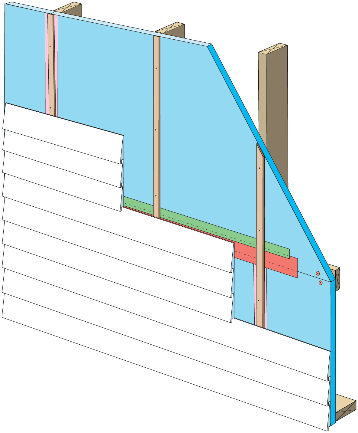
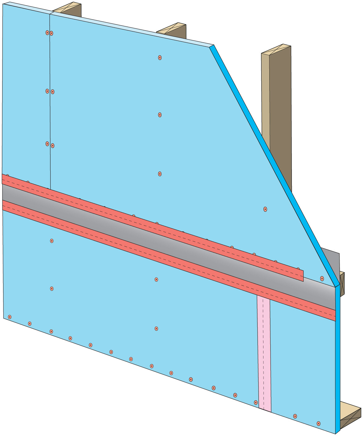
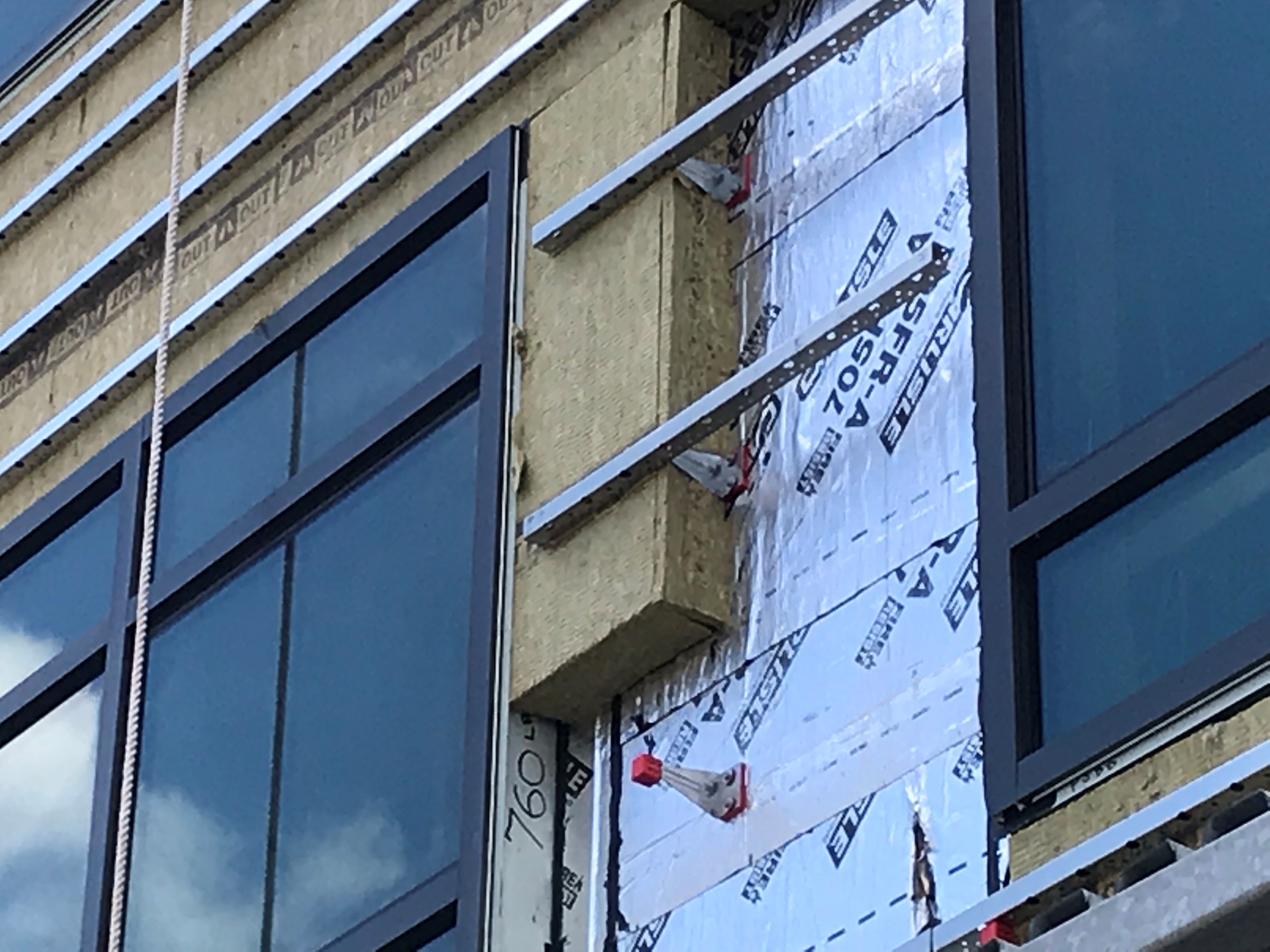
Rigid foam insulation can serve as the drainage plane when all seams are taped. Furring strips provide an air gap behind the cladding.
Image
Image
Image
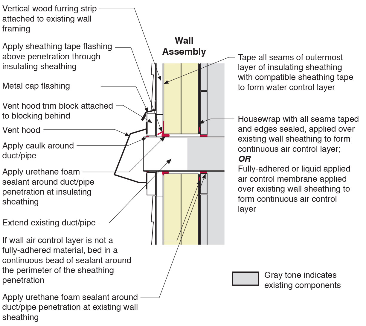
Section view of duct or pipe penetration through exterior wall showing flashing and air sealing details
Image
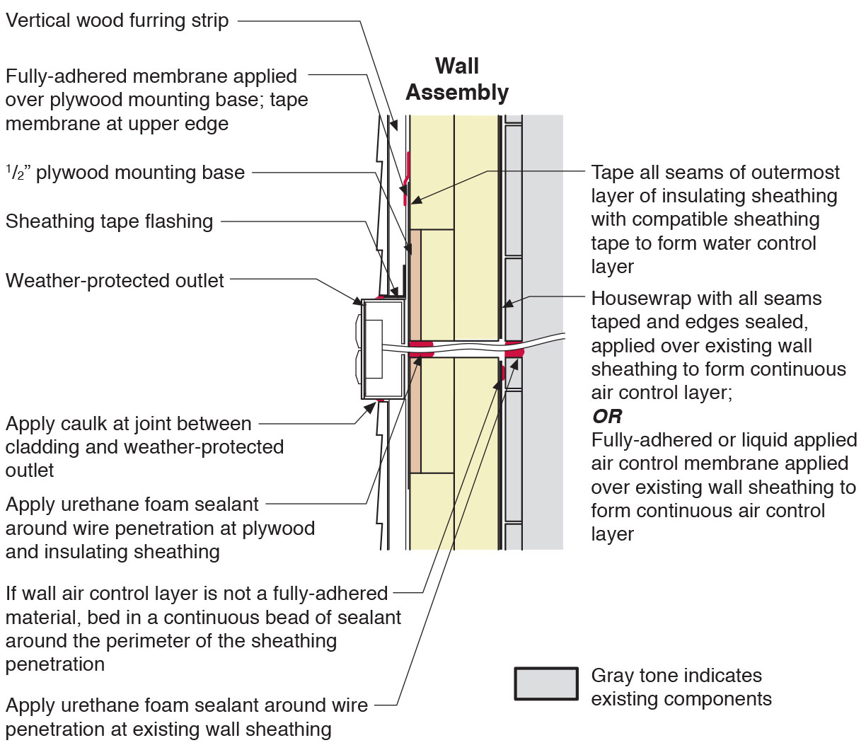
Section view of electric box installation in exterior wall showing flashing and air sealing details
Image

Spray foam adhesive provides an extra water resistant layer to the joints and seams on the inside of attics.
Image

Image
Image
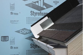
Step 1. Apply roof underlayment over roof deck and up the sidewall over the rigid foam insulation
Image
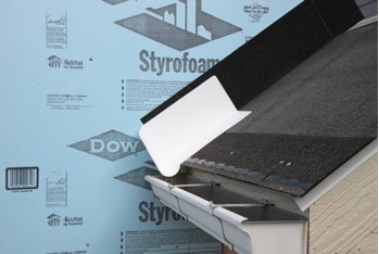
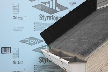
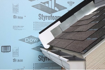
Step 2. Install shingle starter strip then kick-out diverter as first piece of step flashing.
Image
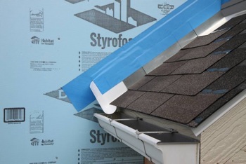
Step 3. Place the first shingle and the next section of sidewall flashing over upper edge of diverter
Image
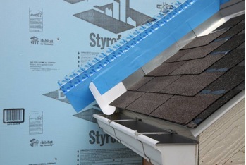
Step 4. Install remaining sidewall flashing, appropriate counter flashing, and shingles
Image
Step 5. Apply self-adhesive flashing over top edge of the wall flashing, diverter, and rigid foam insulation
Image
Image
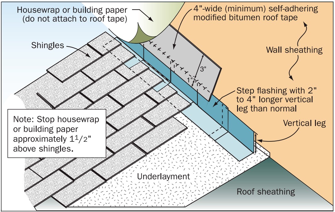
Step and kick-out flashing at all roof-wall intersections extending ≥ 4 in. on wall surface above roof deck and integrated with drainage plane above
Image
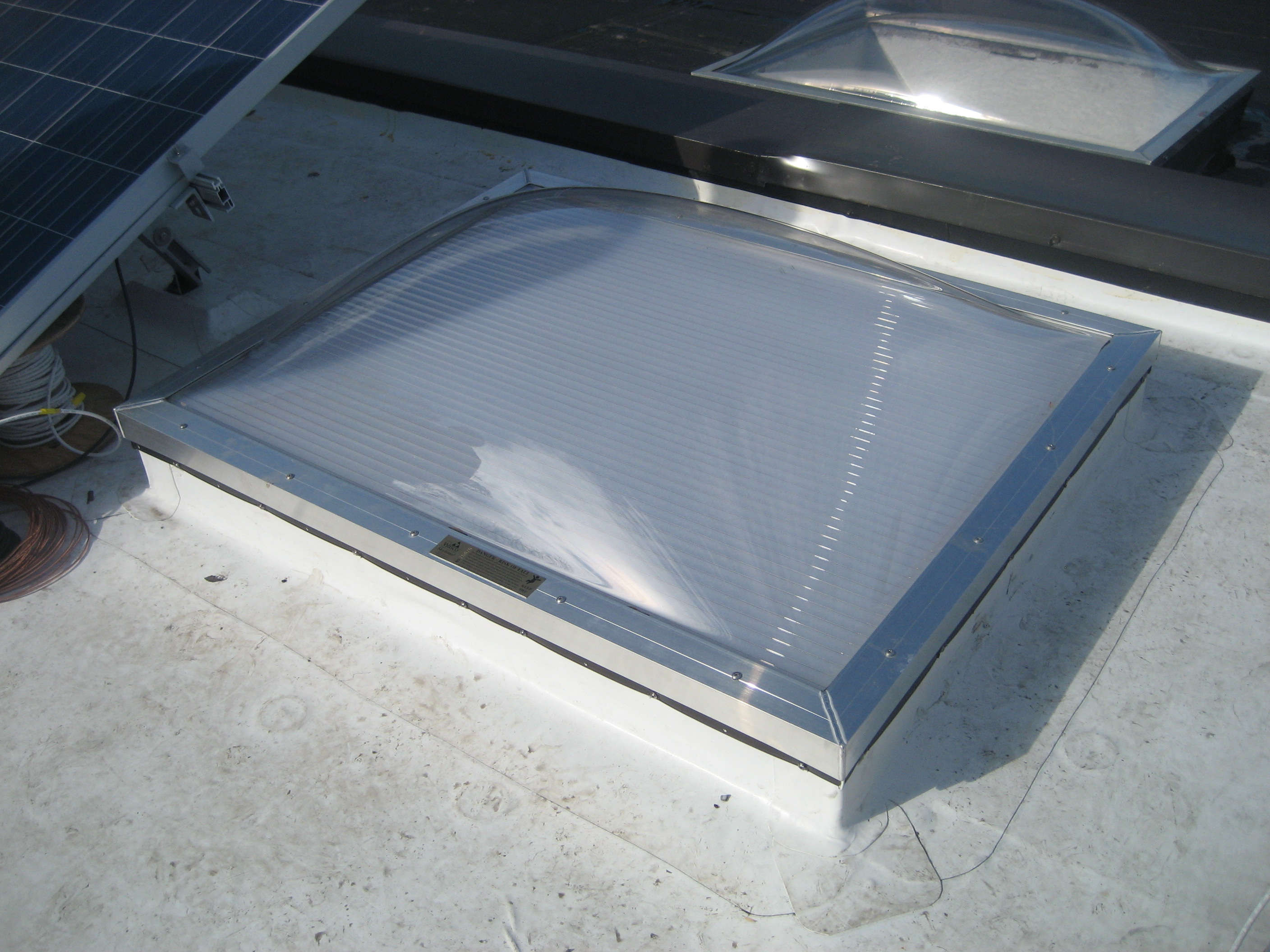
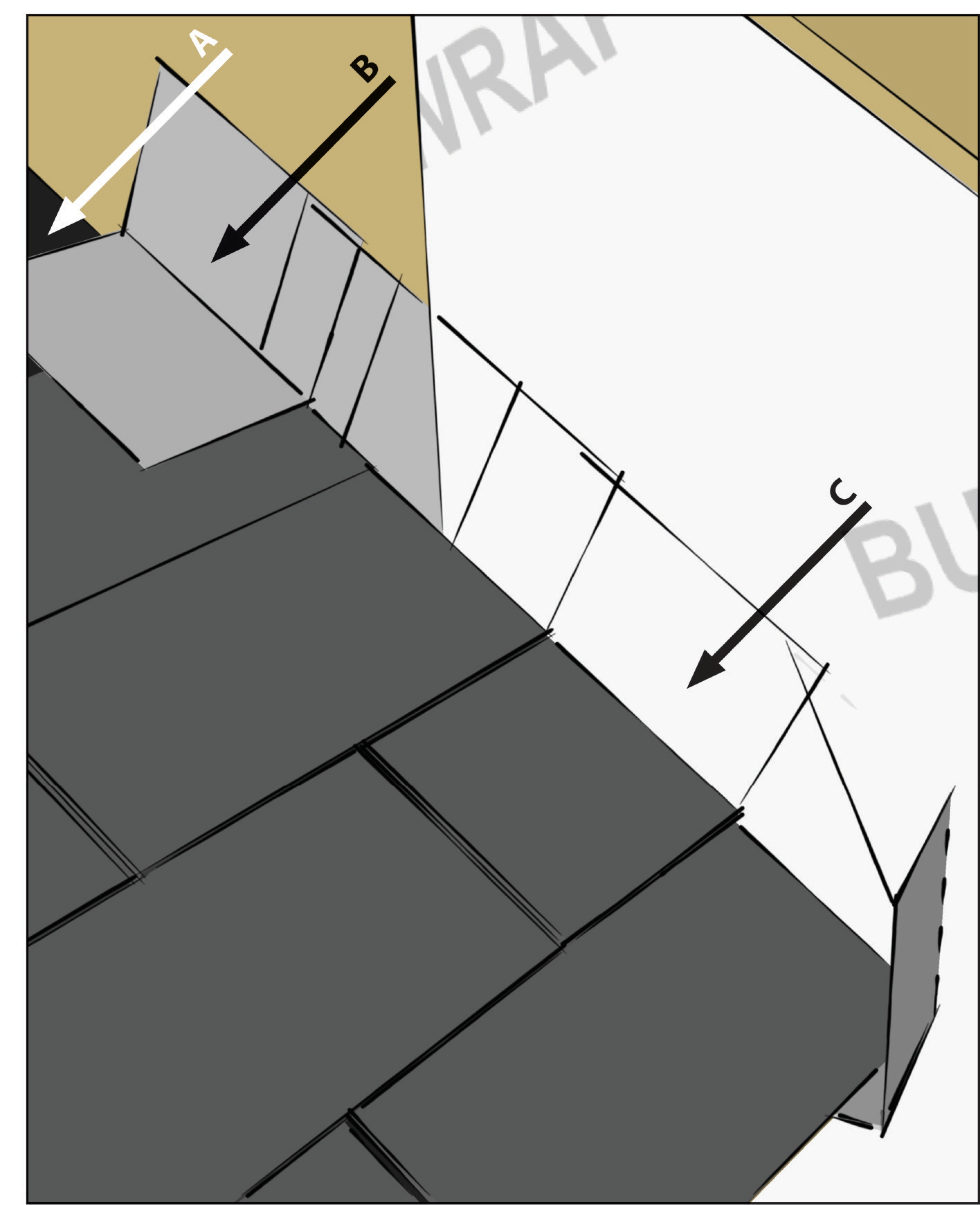
Strips of roofing membrane are used to flash around a skylight on a flat roof retrofit
Image
Image
Image
Tape the joint between the top insulation sheet and the Z-flashing with 2" wide tape to improve air tightness
Image
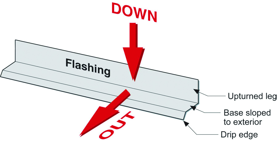
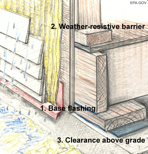
The “down” and “out” approach to flashing – metal flashing directs water down and out of building assemblies
Image

The blocking is completely flashed with roofing membrane before the PV rack hardware is attached on a flat roof
Image

The fluid-applied asphalt coating provides a weather-resistant, moisture resistant layer around the house, serving as a continuous drainage plane and flashing for window and door openings.
Image
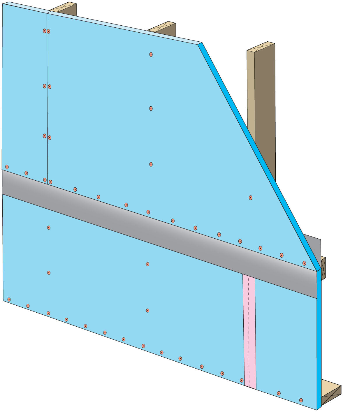
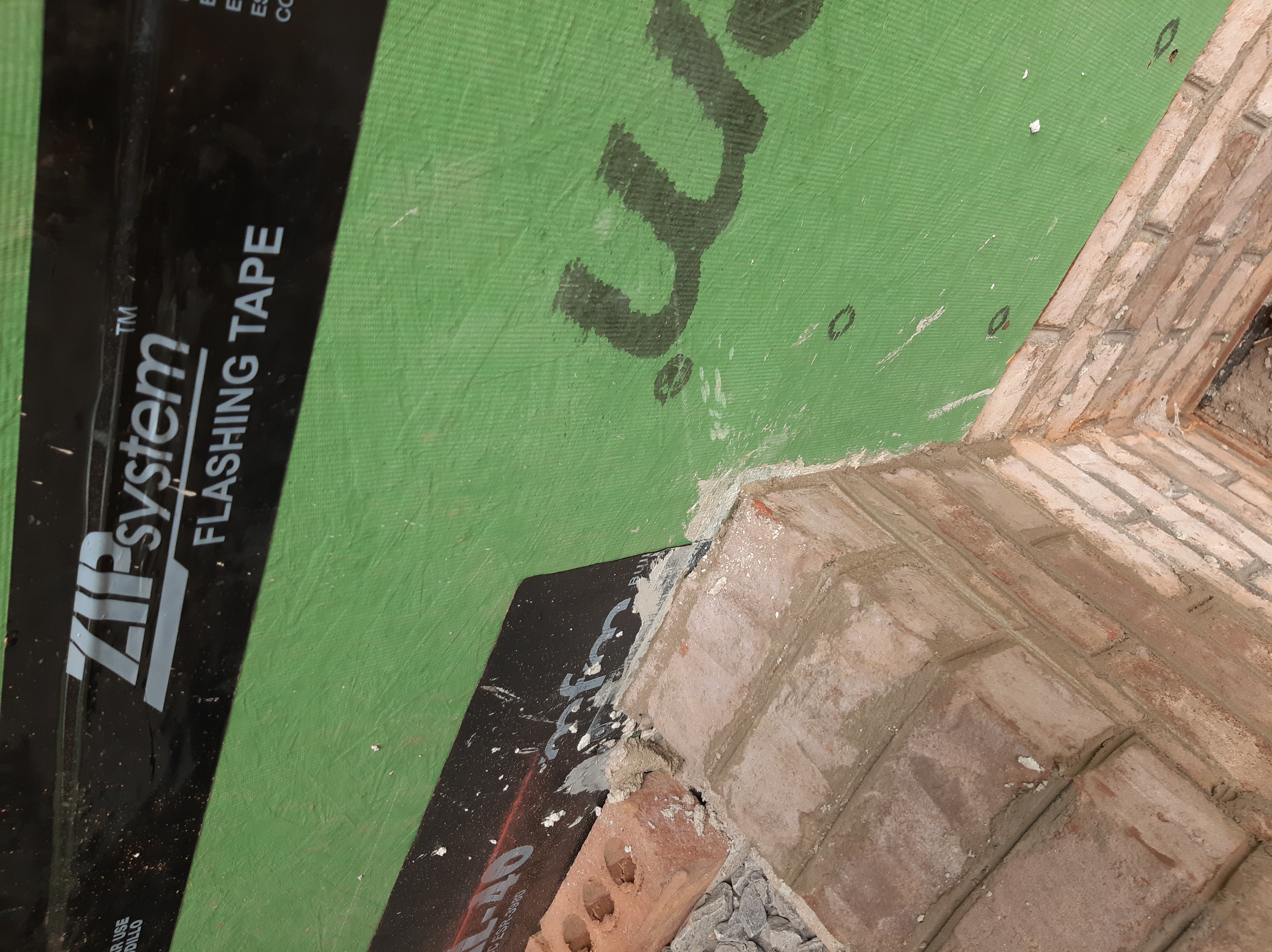
The home is sheathed with rigid foam insulation and all seams and holes are taped to provide a continuous air barrier.
Image
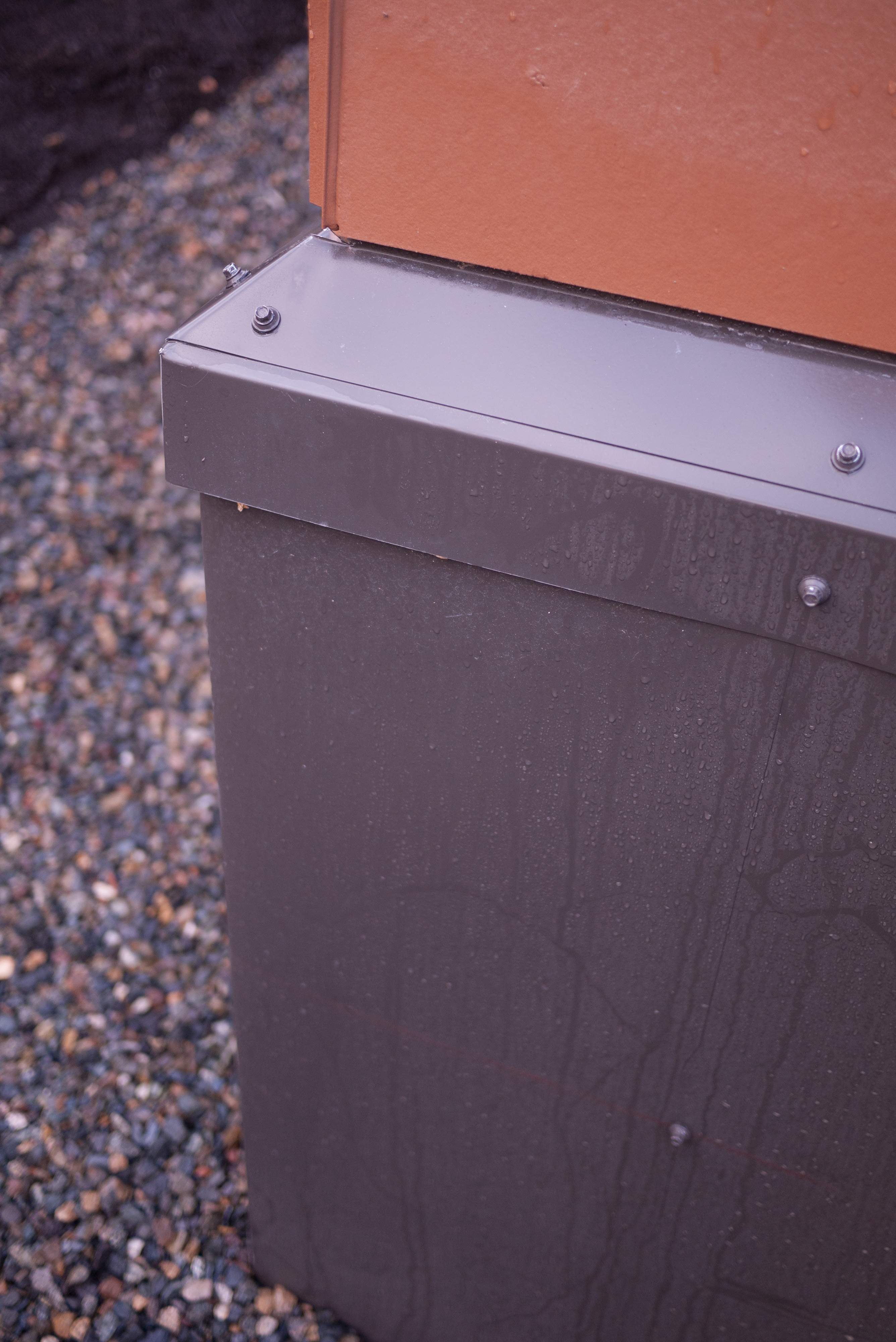
The ICF foundation wall of this home is covered with metal flashing before the siding is installed.
Image

The retrofitted flat roof has PV panels and walking mats installed over the roofing membrane
Image
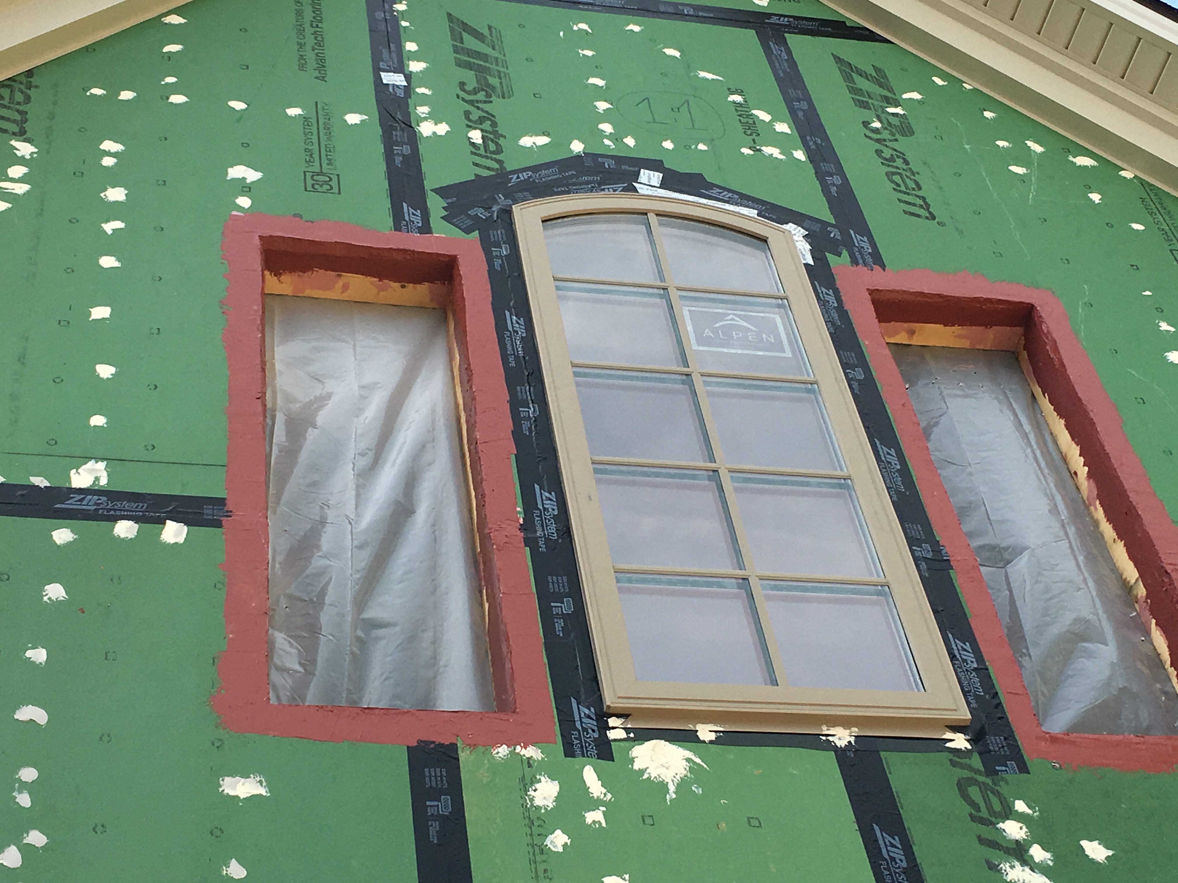
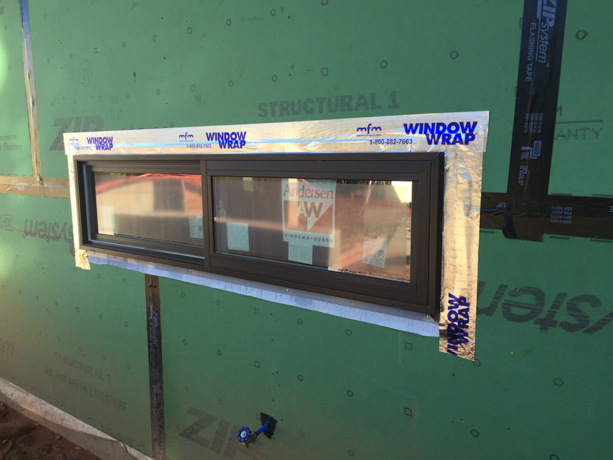
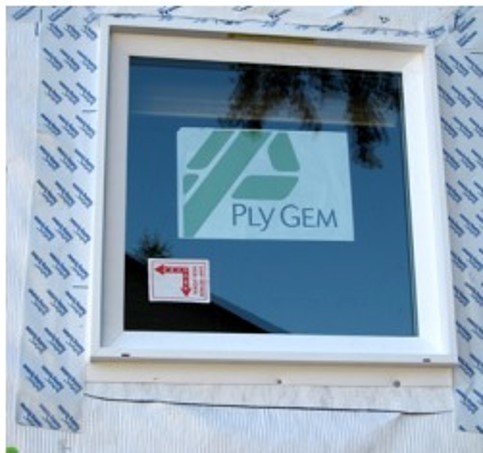
The rough openings for the windows are flashed with a paint-on flashing product then the windows are installed and additional flashing tape is installed over the flashing. Nail holes are sealed with caulk.
Image
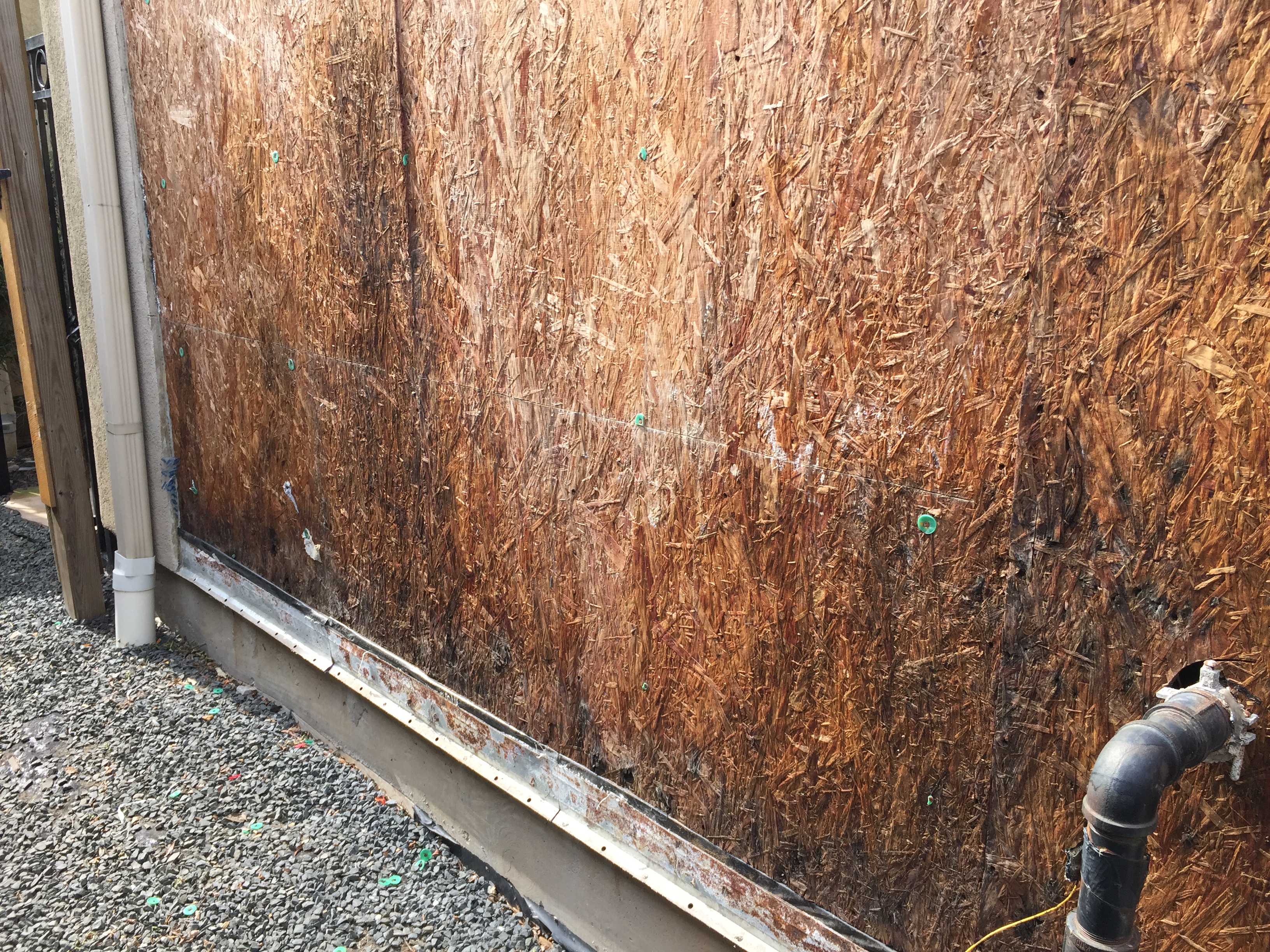
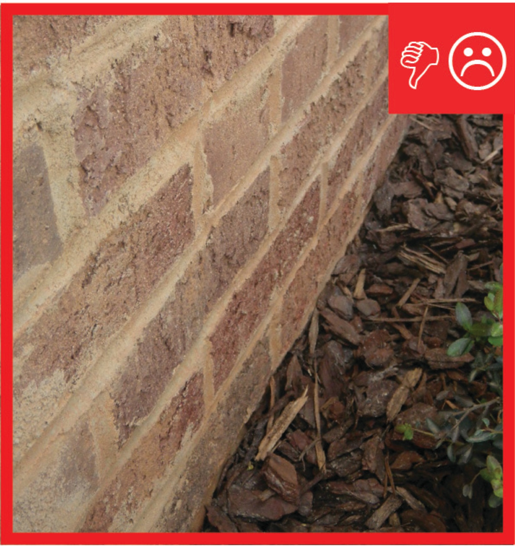
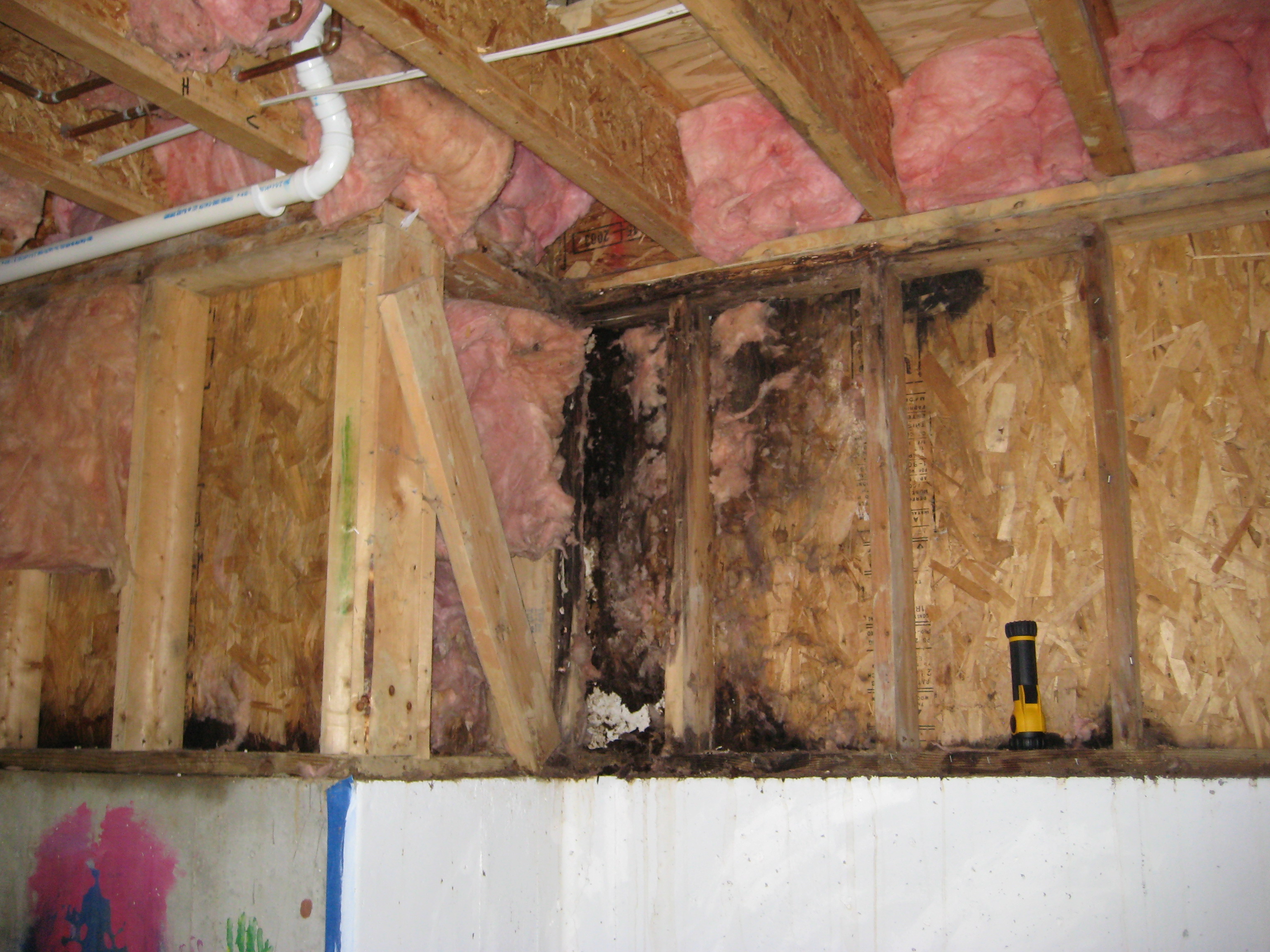
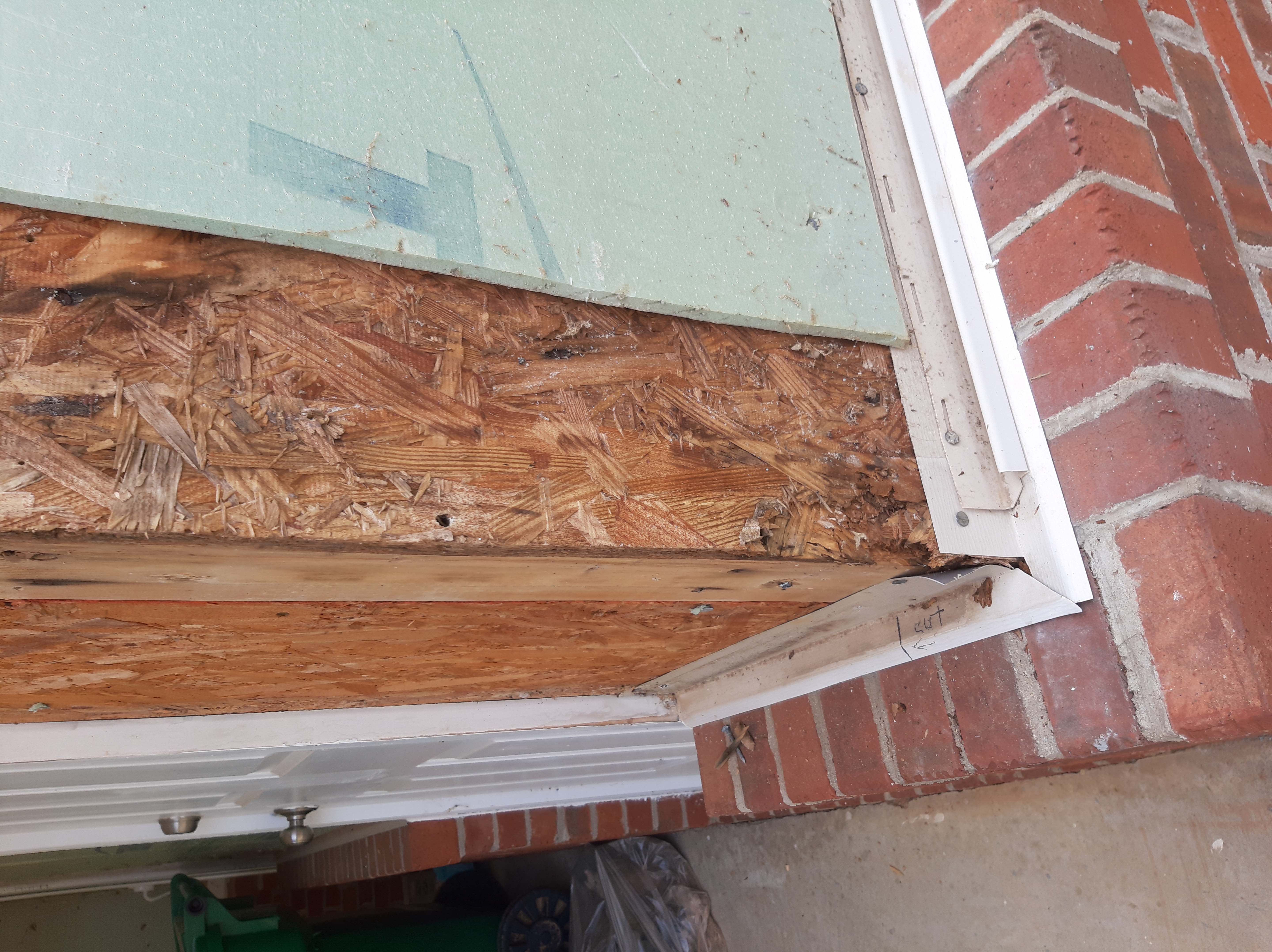
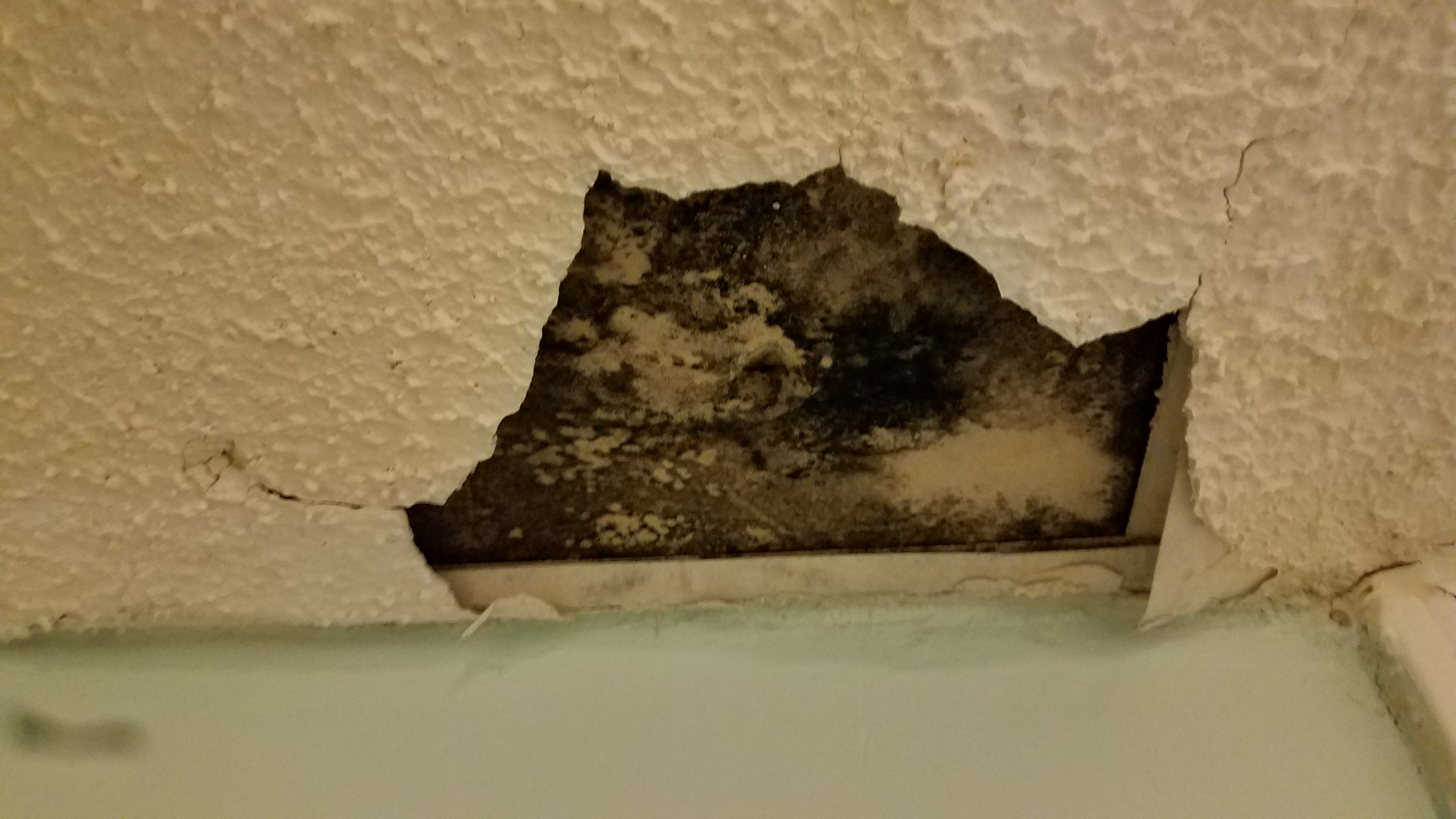
The sheathing has rotted because there was not a sufficient drainage gap behind the stucco cladding
Image
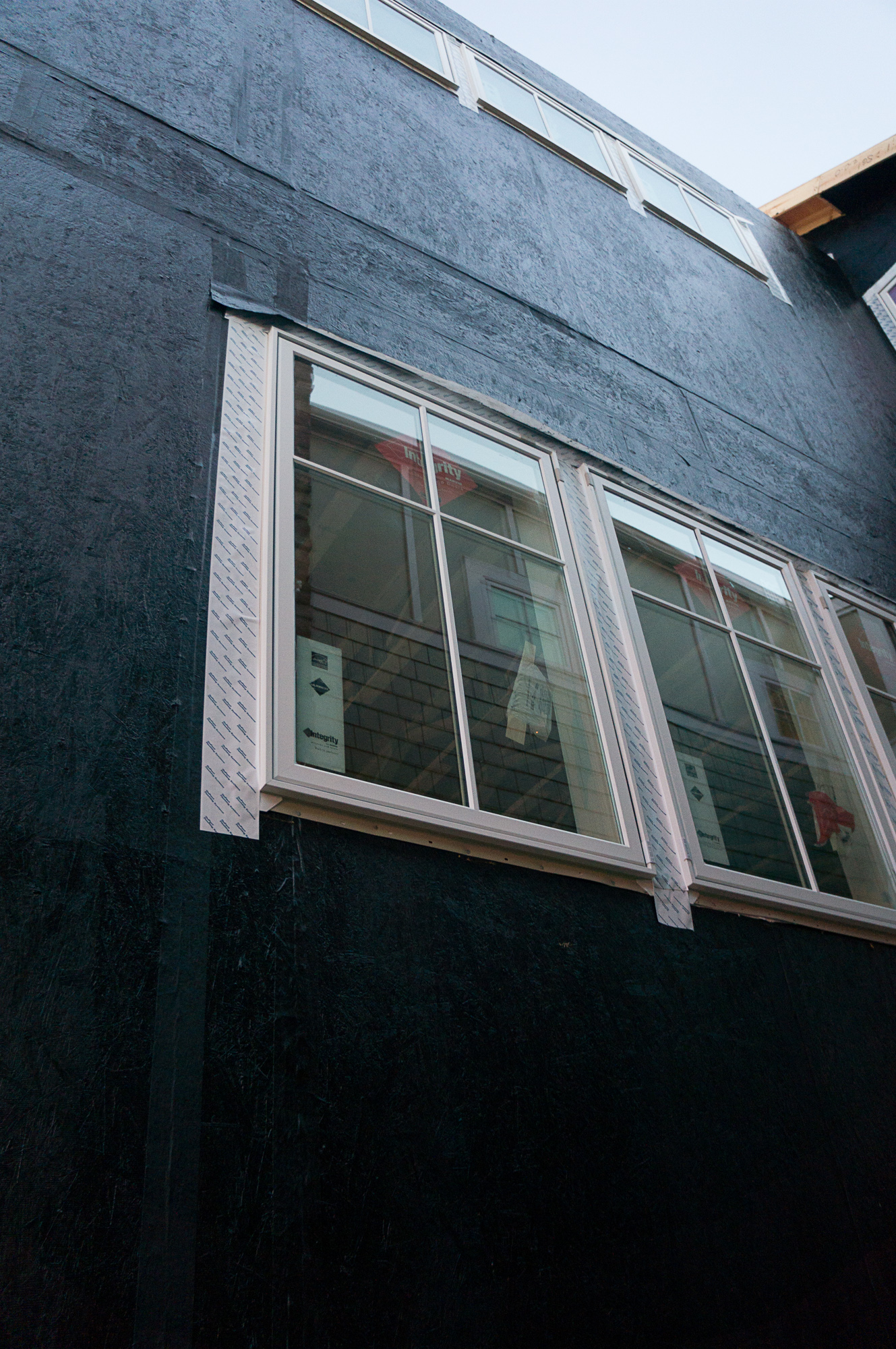
The tape window flashing here is integrated with the roller-applied weather-resistant barrier.
Image
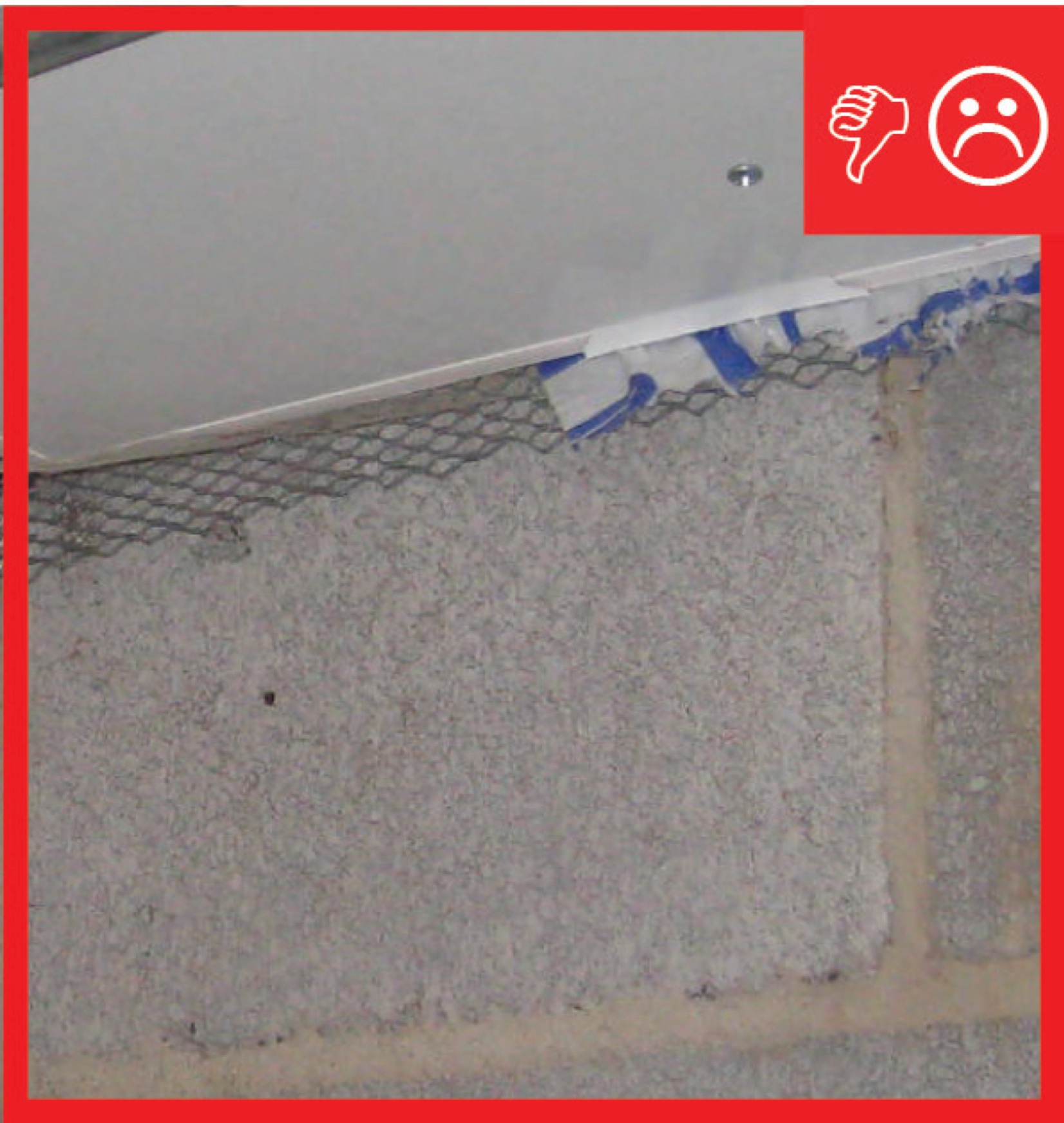
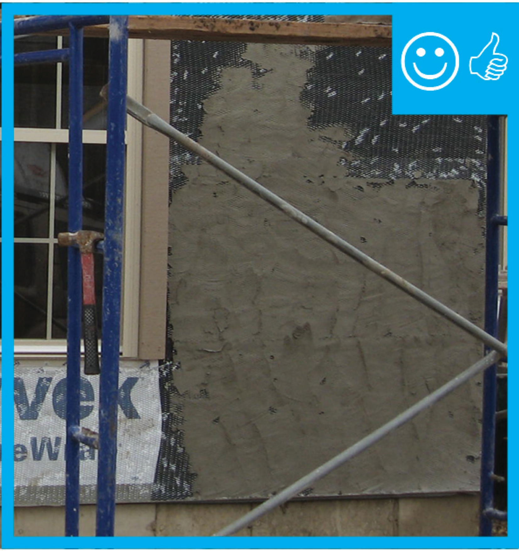
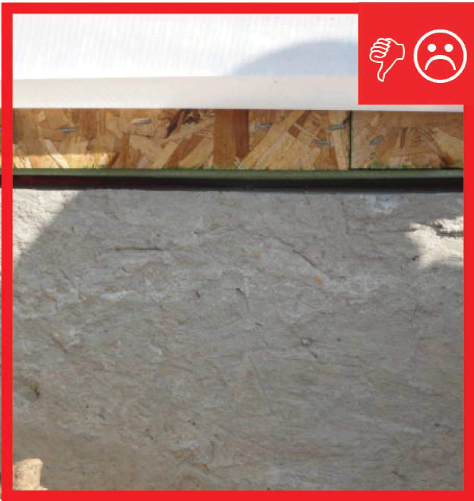
The water-resistant barrier, weep screed, and stucco lathe are not properly layered
Image
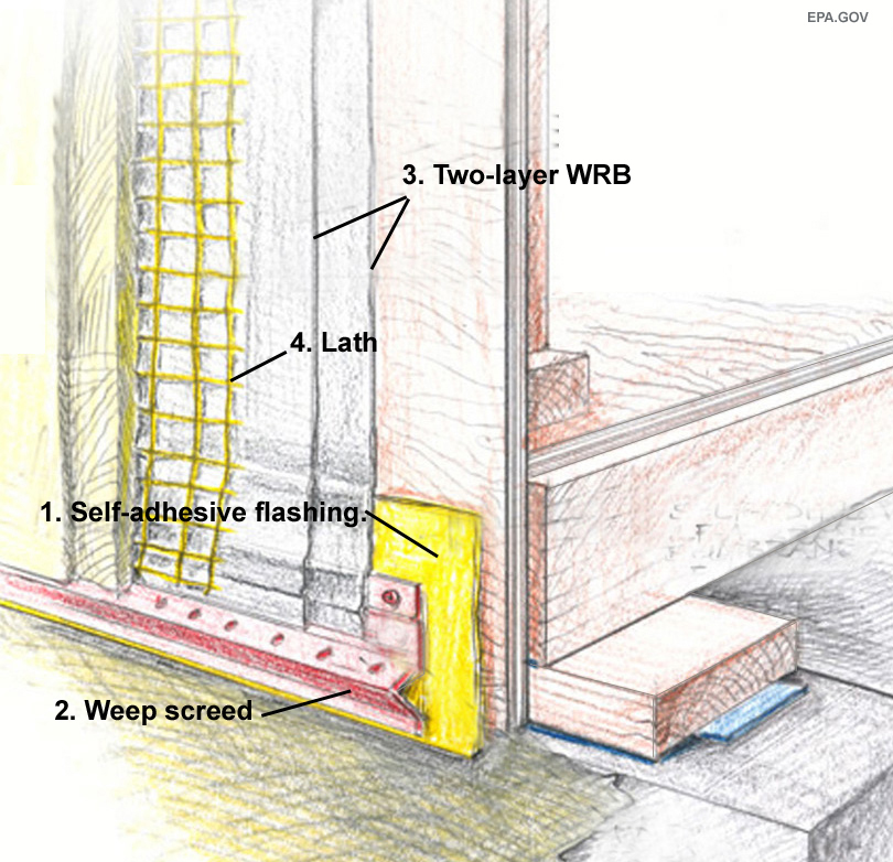
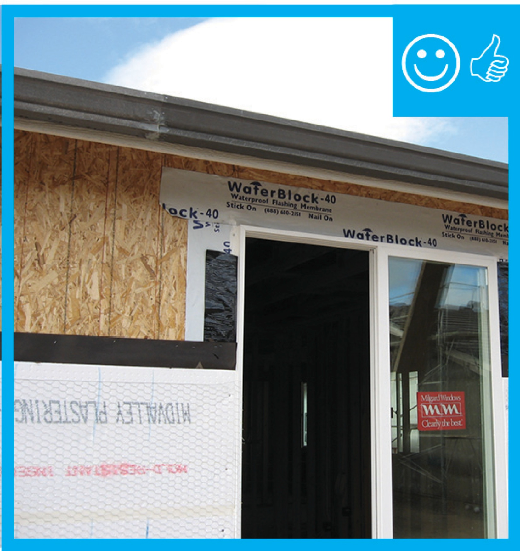
The water-resistant barrier, weep screed, and stucco lathe are properly layered and will create a complete drainage system
Image
Image
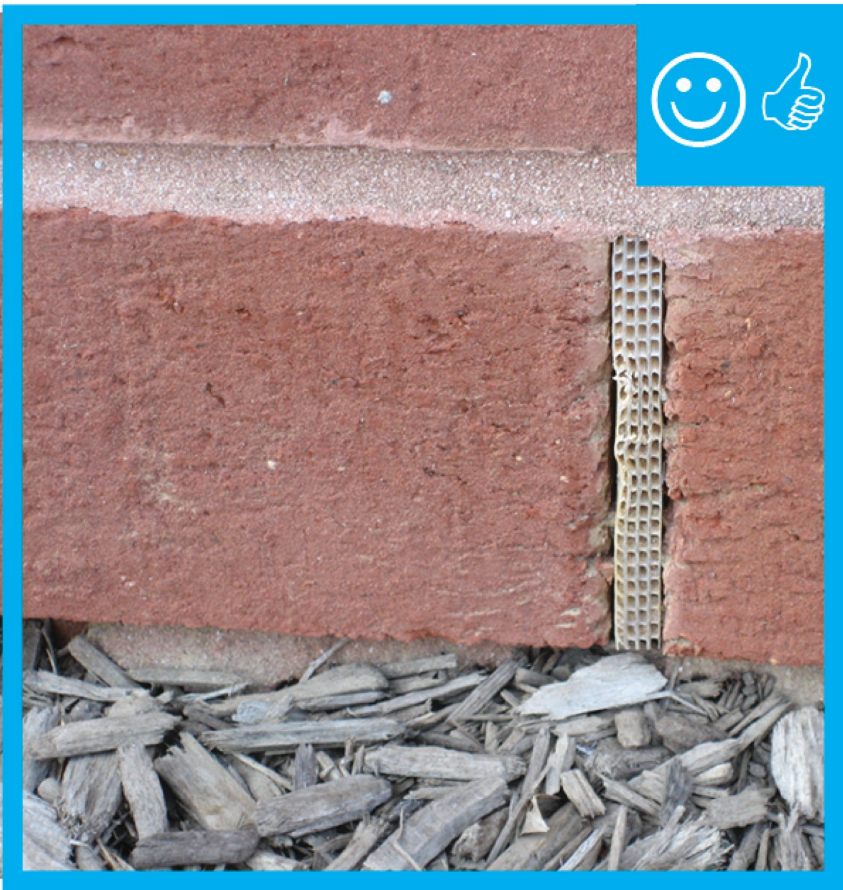
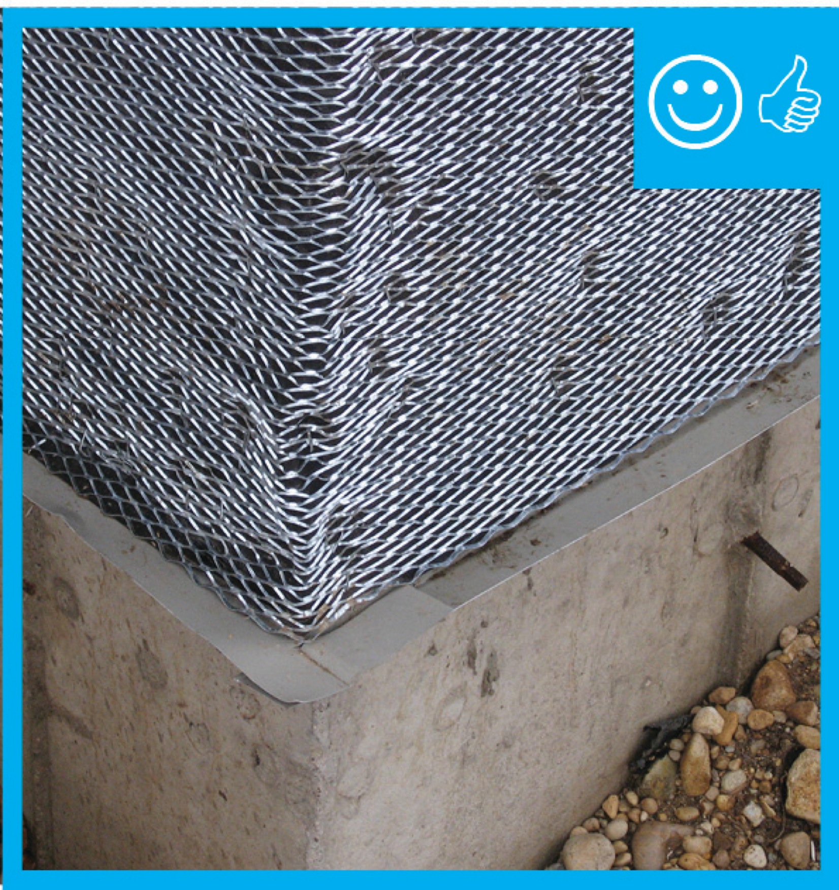
The weep holes are spaced at the correct distance to provide a complete drainage system
Image

Image
Image

The windows in this building are connected to the fully adhered water and air control layer using fluid-applied flashing
Image
Image
Image
Image
Image
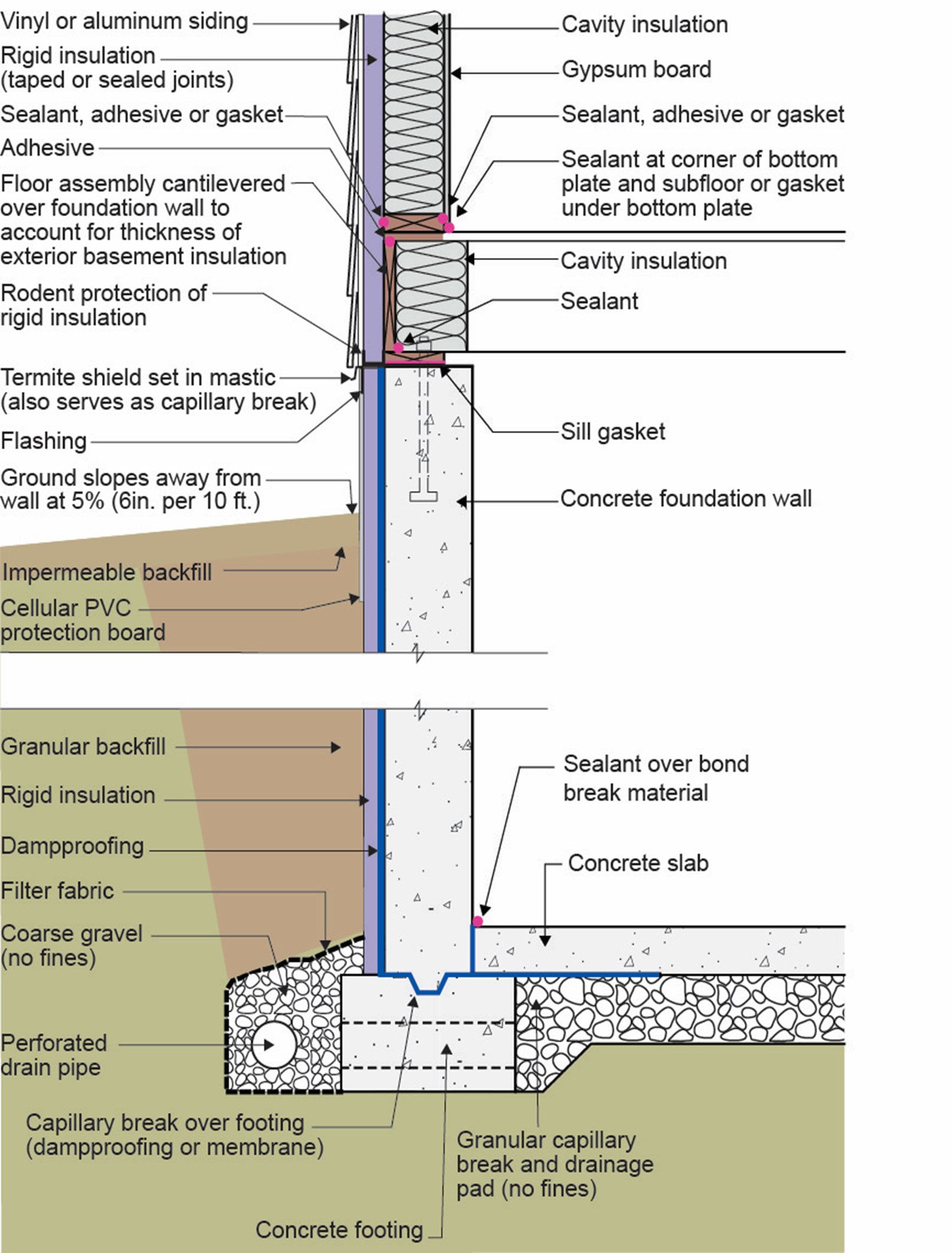
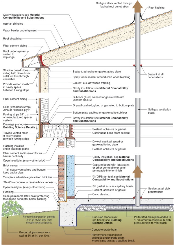
This basement is insulated on the exterior with rigid foam over dampproofing, with granular backfill and footing drains to facilitate drainage away from the foundation, a termite shield to protect from pests, and cellular PVC to protect the rigid foam.
Image
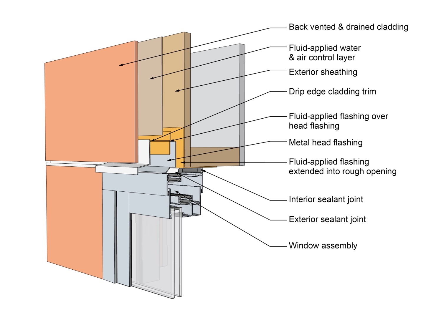
This drawing shows key head details for a window installation using a fluid-applied flashing on a wall with a fluid-applied water and air control layer
Image
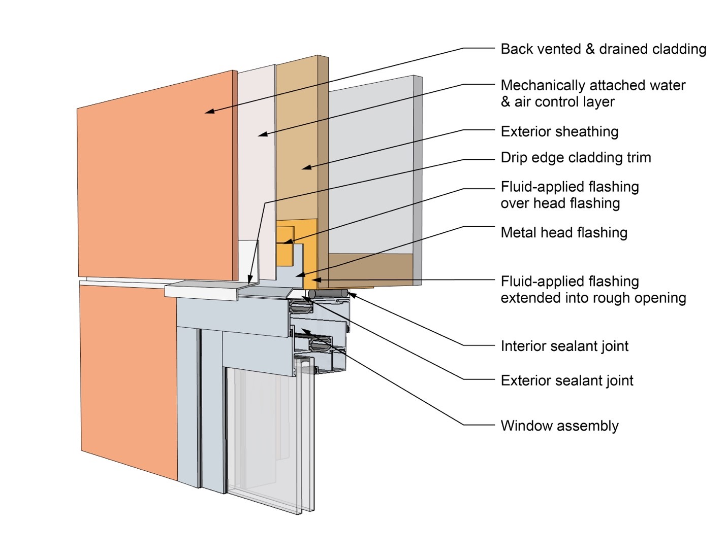
This drawing shows key head details for a window installation using a fluid-applied flashing on a wall with a mechanically attached water and air control layer
Image
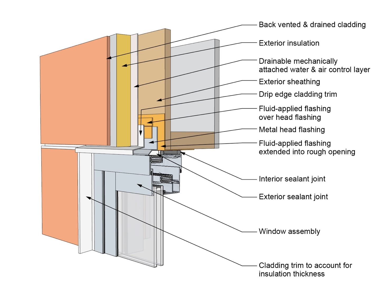
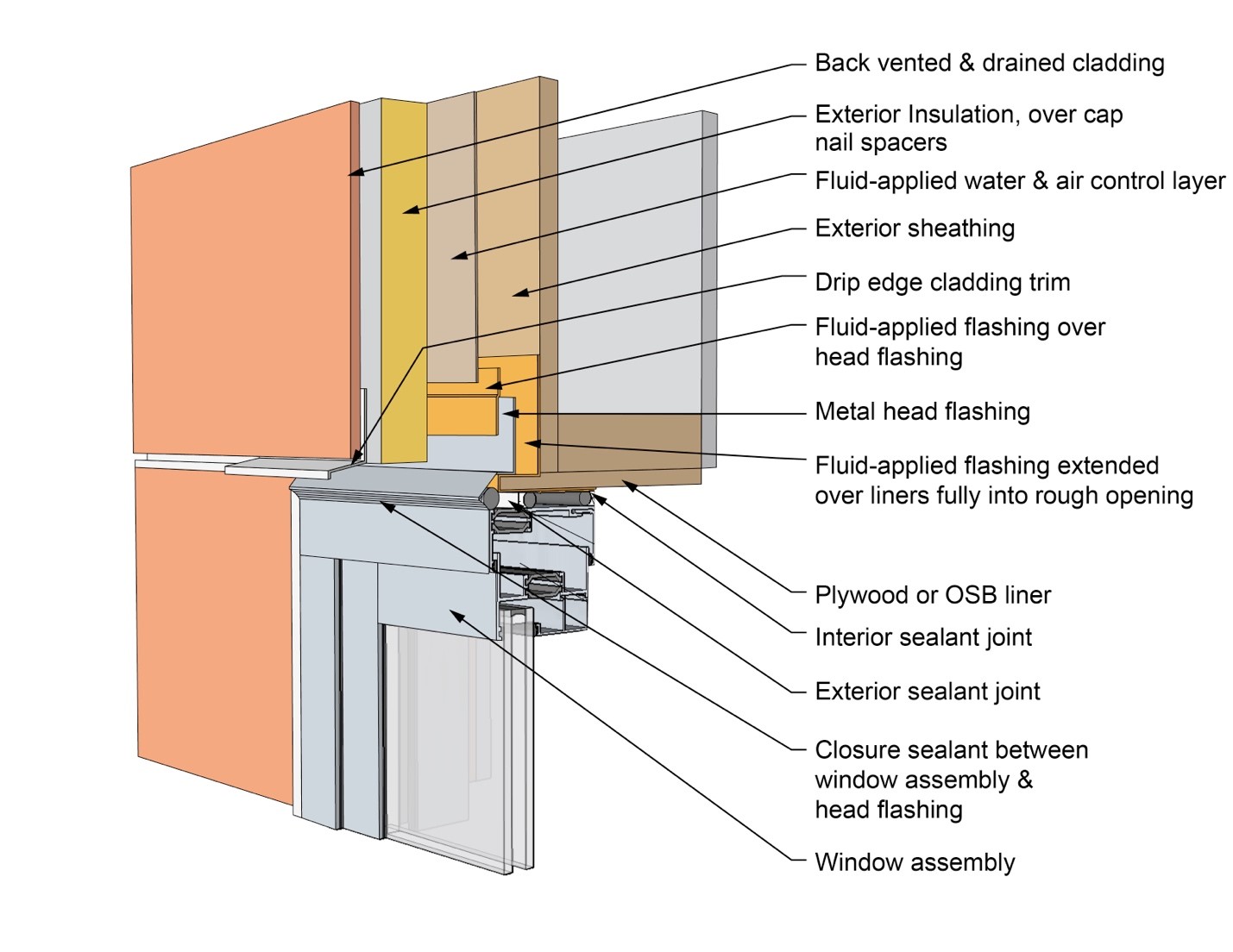
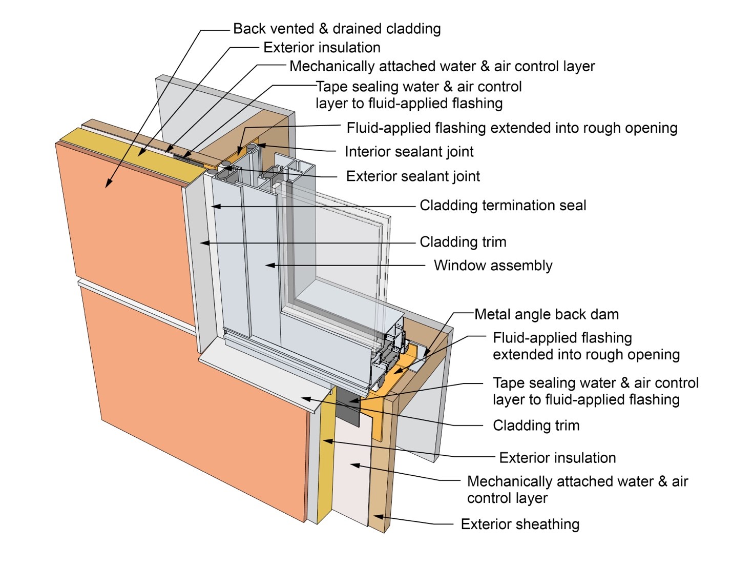
This drawing shows key head details for a window installation using a fluid-applied flashing on a wall with a mechanically attached water and air control layer and continuous insulation
Image
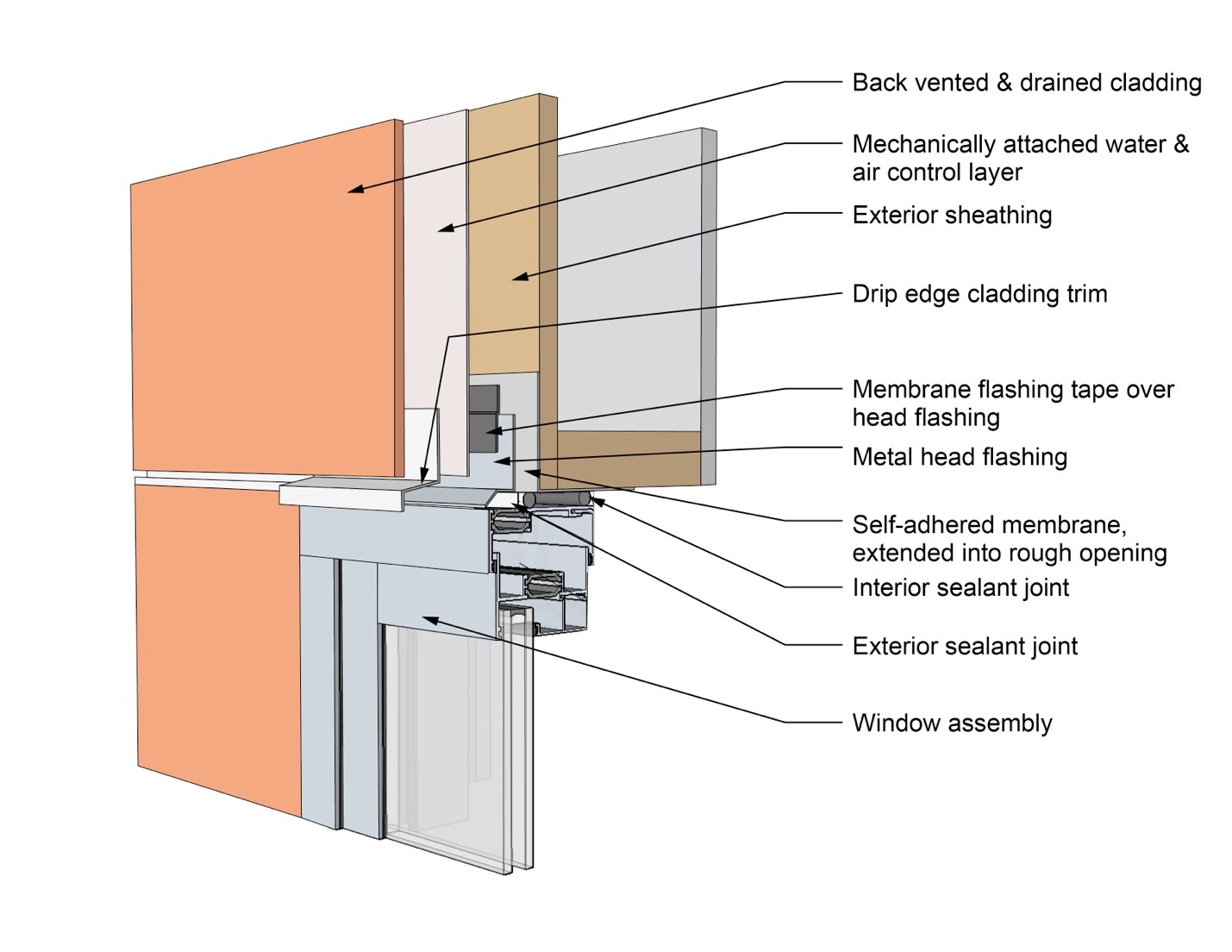
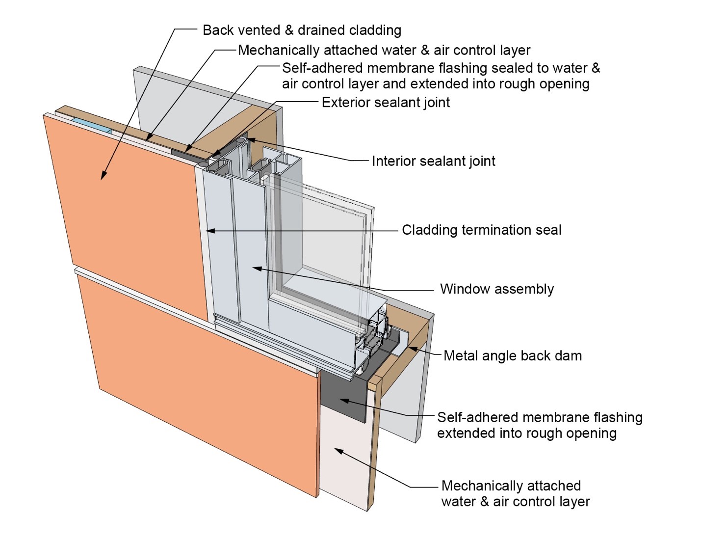
This drawing shows key head details for a window installation using a self-adhered membrane tape flashing on a wall with a mechanically attached water and air control layer
Image
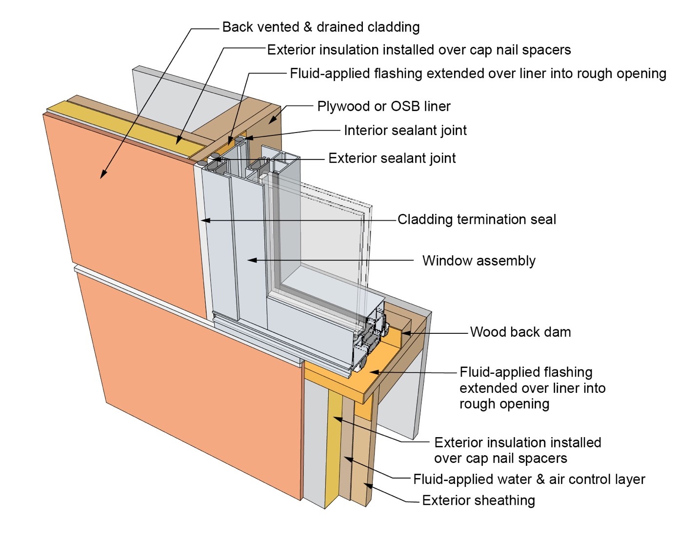
This drawing shows key head details for an “outie” window installation using a fluid-applied flashing on a wall with a fluid-applied water and air control layer and continuous insulation
Image
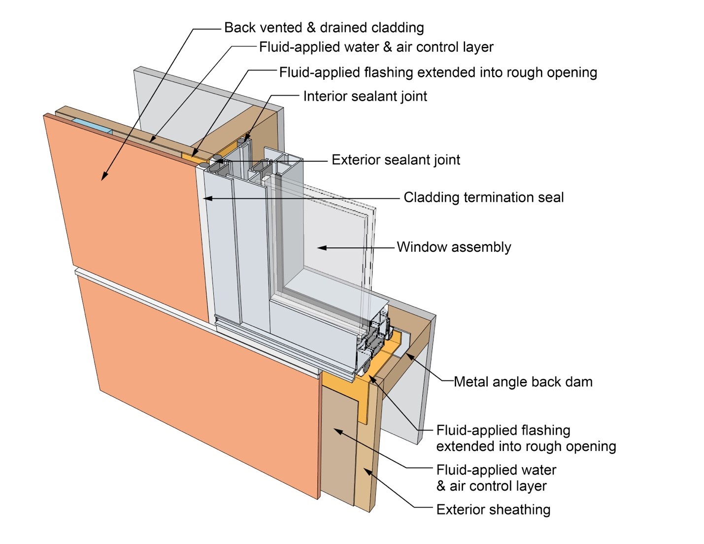
This drawing shows key jamb details for a window installation using a fluid-applied flashing on a wall with a fluid-applied water and air control layer
Image
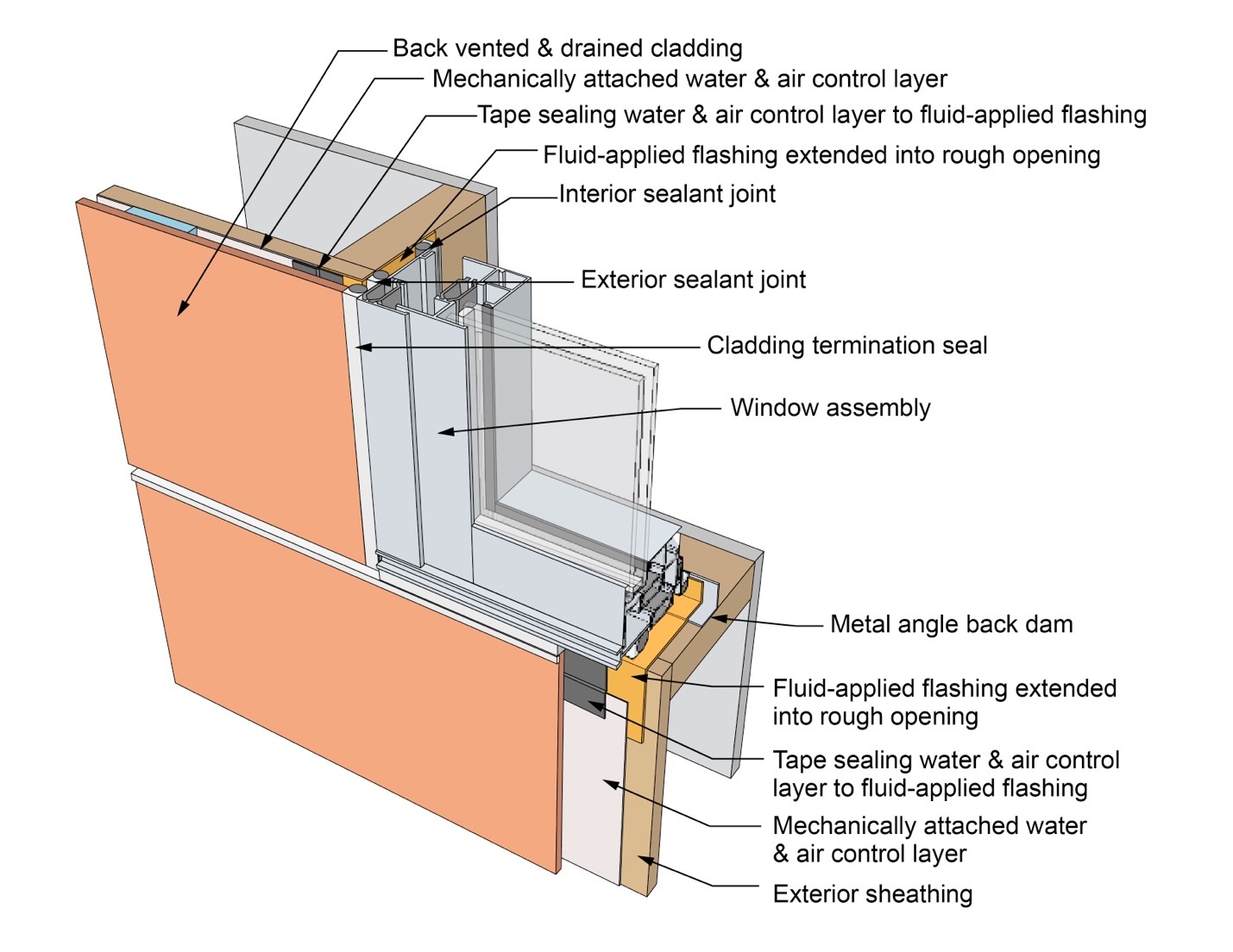
This drawing shows key jamb details for a window installation using a fluid-applied flashing on a wall with a mechanically attached water and air control layer
Image
This drawing shows key jamb details for a window installation using a fluid-applied flashing on a wall with a mechanically attached water and air control layer and continuous insulation
Image
This drawing shows key jamb details for a window installation using a self-adhered membrane tape flashing on a wall with a mechanically attached water and air control layer
Image
This drawing shows key jamb details for an “outie” window installation using a fluid-applied flashing on a wall with a fluid-applied water and air control layer and continuous insulation
Image
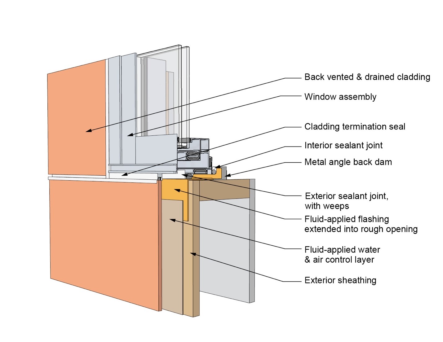
This drawing shows key sill details for a window installation using a fluid-applied flashing on a wall with a fluid-applied water and air control layer
Image
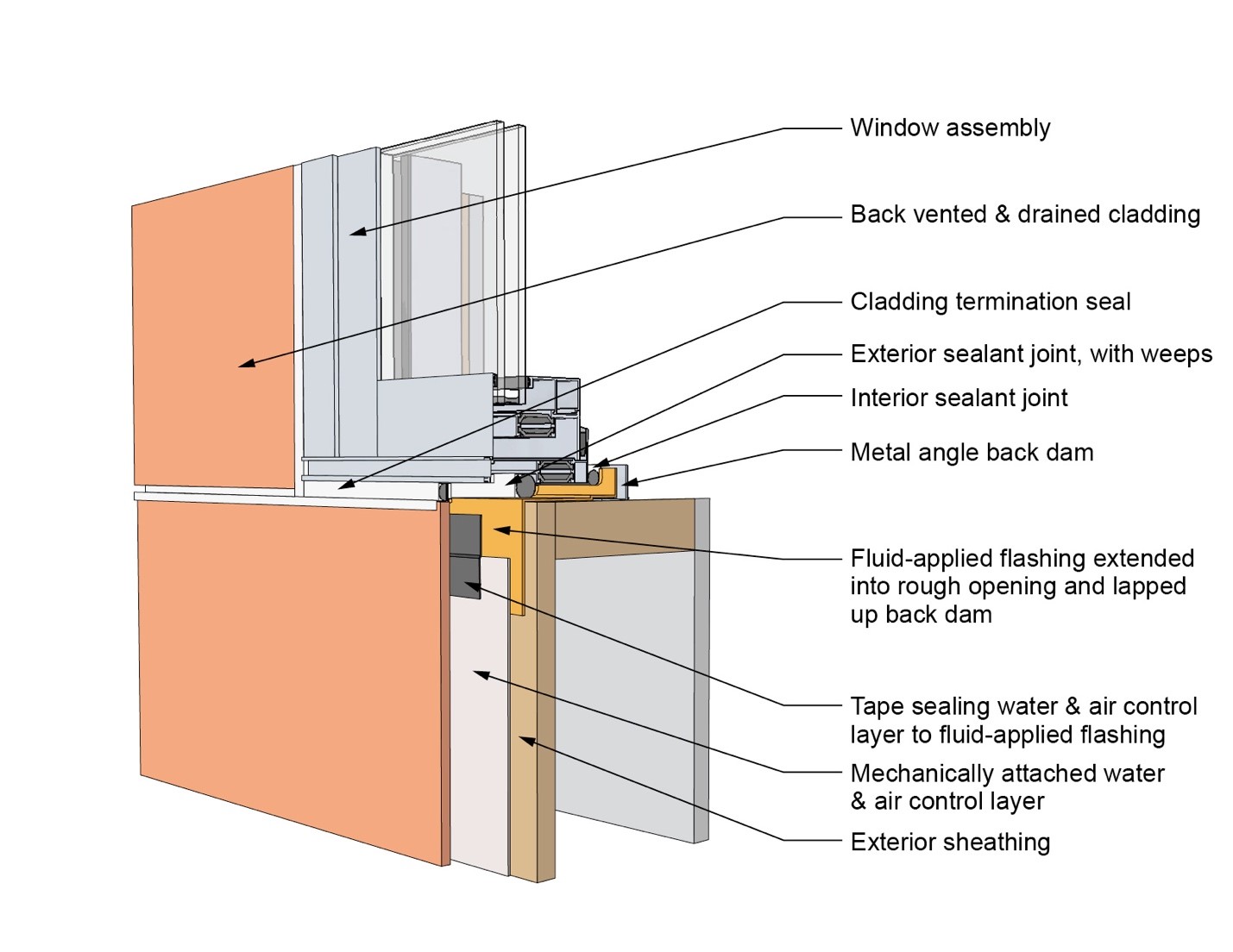
This drawing shows key sill details for a window installation using a fluid-applied flashing on a wall with a mechanically attached water and air control layer
Image
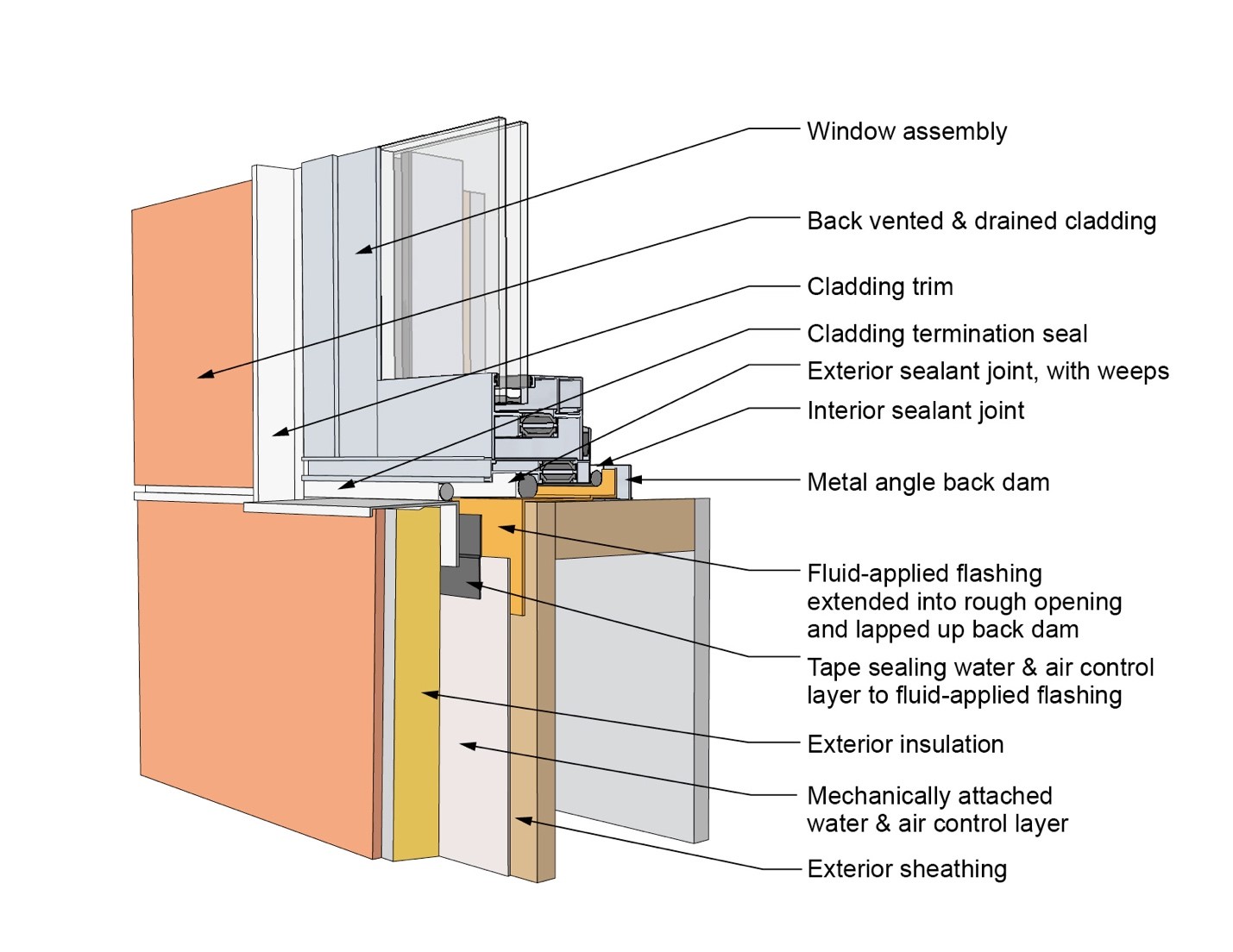
This drawing shows key sill details for a window installation using a fluid-applied flashing on a wall with a mechanically attached water and air control layer and continuous insulation
Image
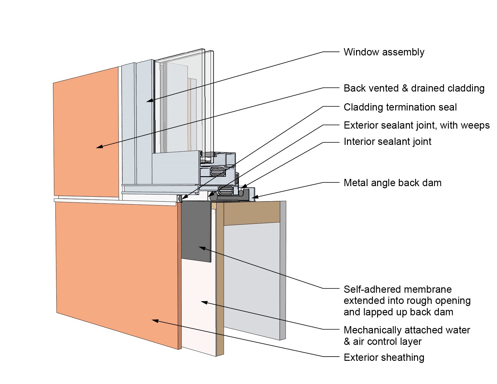
This drawing shows key sill details for a window installation using a self-adhered membrane tape flashing on a wall with a mechanically attached water and air control layer
Image
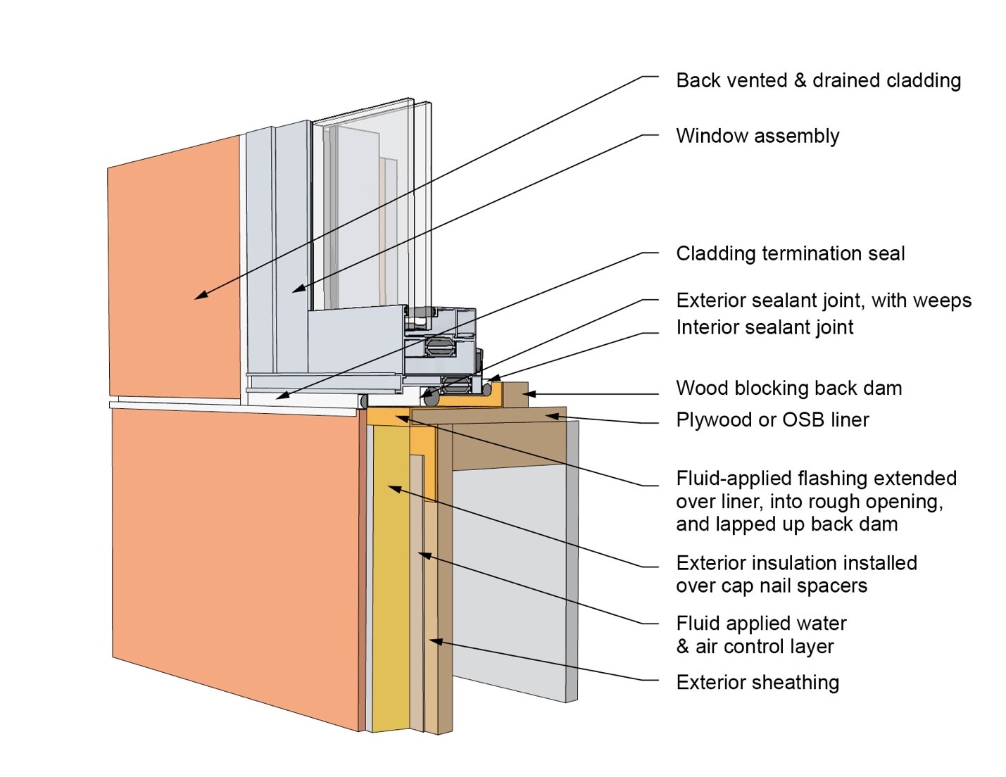
This drawing shows key sill details for an “outie” window installation using a fluid-applied flashing on a wall with a fluid-applied water and air control layer and continuous insulation
Image
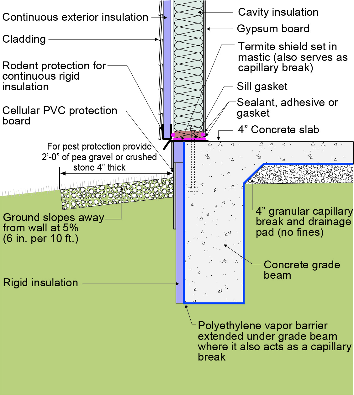
This exterior insulated slab-on-grade monolithic grade beam foundation is protected from pests by termite shield at the sill plate, borate-treated framing, flashing at end of wall insulation, brick veneer over slab-edge insulation, and rock ground cover.
Image
This exterior wall retrofit permits drying to the exterior of a sill plate installed on an untreated flat foundation wall
Image
This exterior wall retrofit permits drying to the exterior of a sill plate installed on an untreated irregular foundation wall
Image
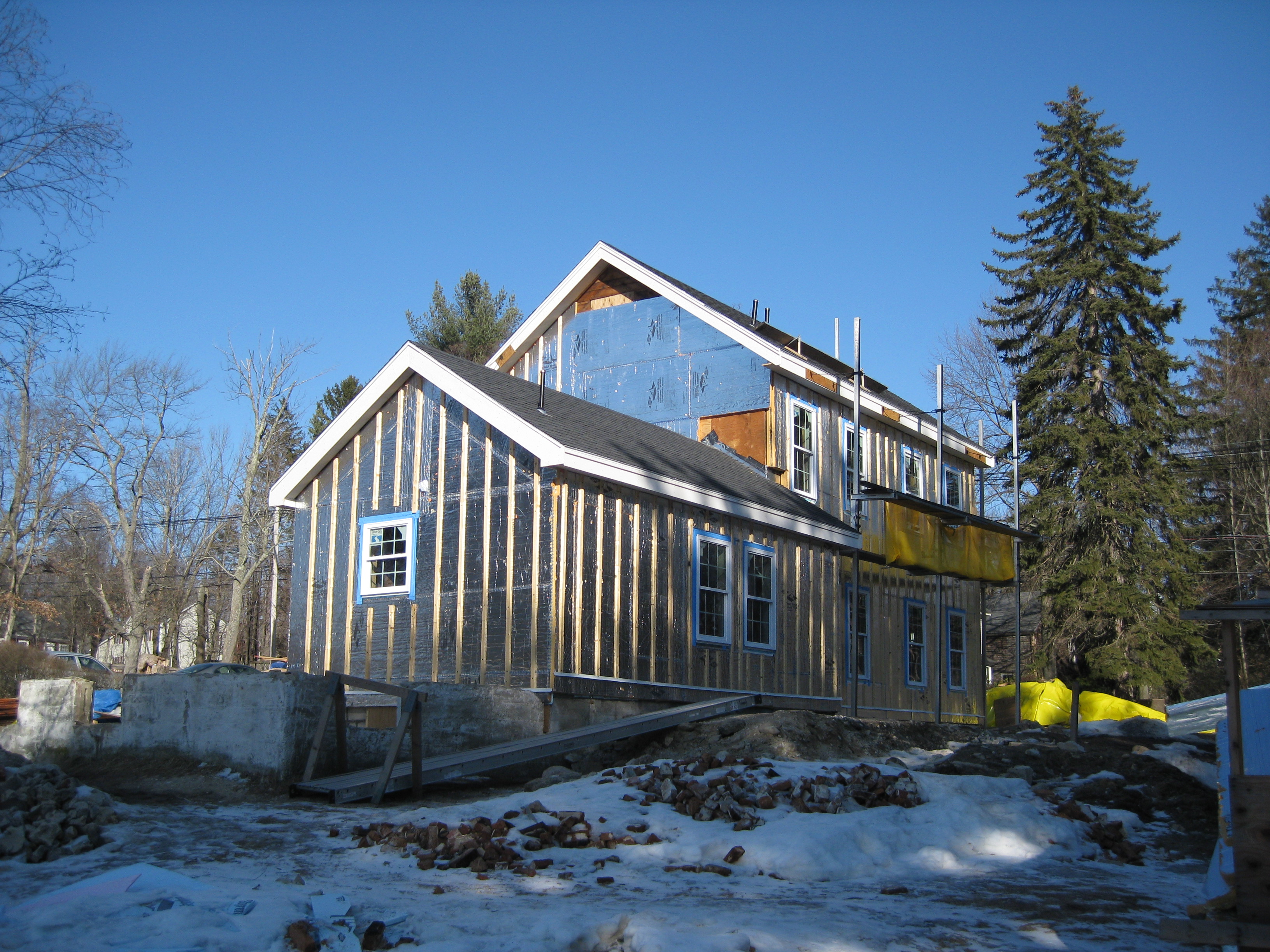
This farmhouse was retrofit by removing the existing siding and adding taped insulated sheathing and battens before installing new siding
Image
This house design in the Hot-Humid climate uses a slab foundation, masonry walls, and an Exterior Insulation Finish System (EIFS) cladding.
Image
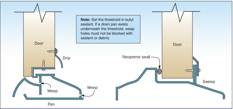
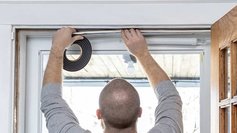
Threshold Sweep Flashing protects the door and helps to keep out wind-driven rain.
Image
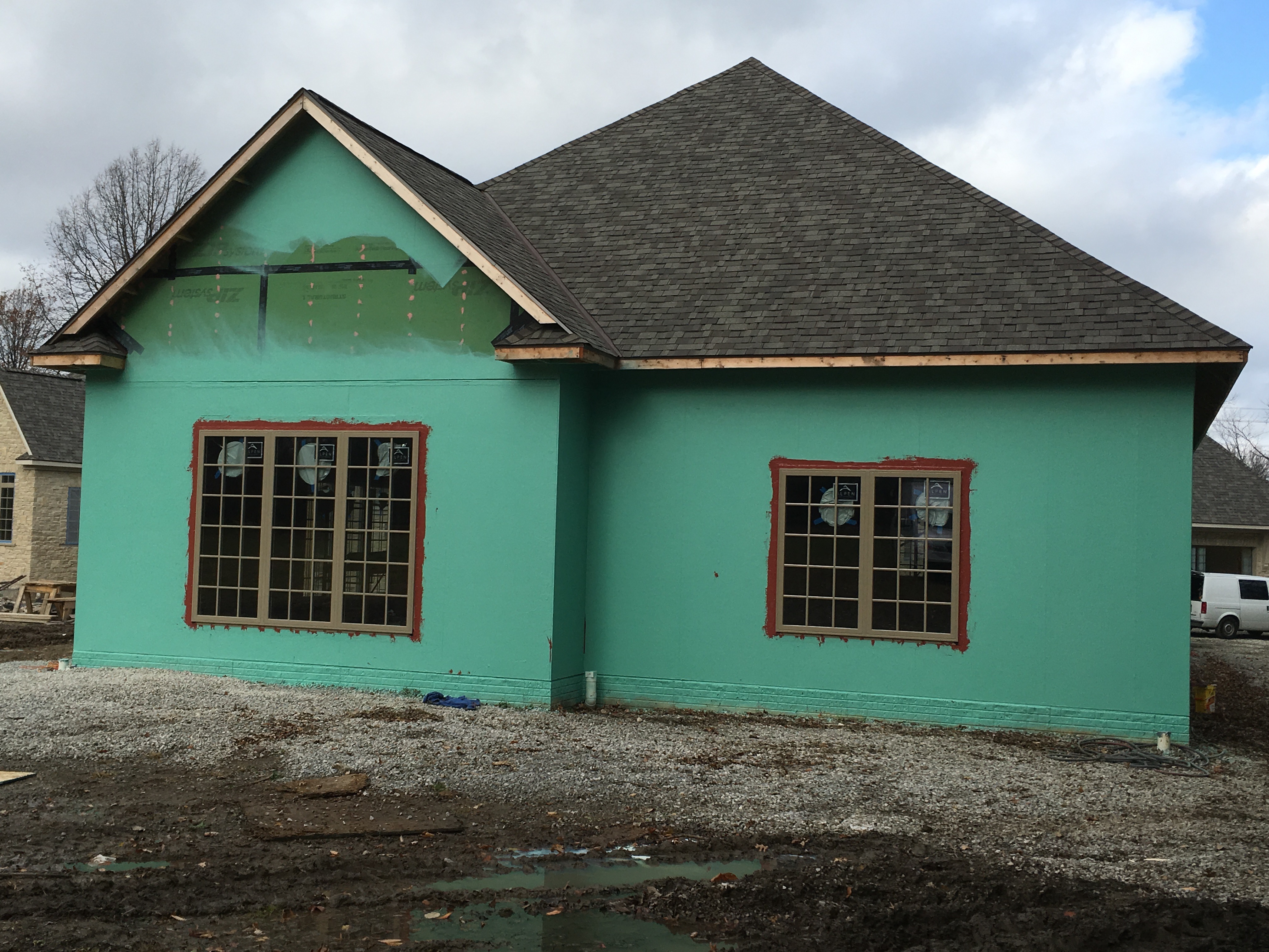
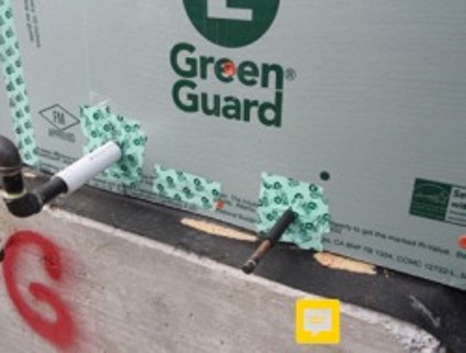
Two types of paint-on flashing (green and red) are installed on the walls and around the windows, over the coated sheathing which is taped at the seams.
Image
Image
Image
Image

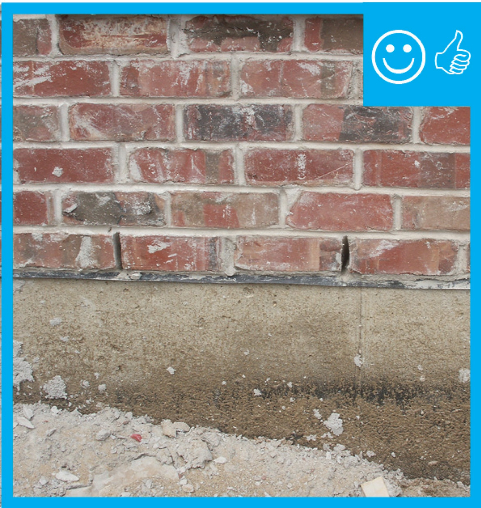
Weep holes: Rope inserted in the head joist between bricks will allow water to weep out of the base of the wall assembly
Image
Image
Image
Windows are installed as “outies” in this wall assembly using a self-adhered membrane water and air control layer with continuous exterior insulation
Image
Image

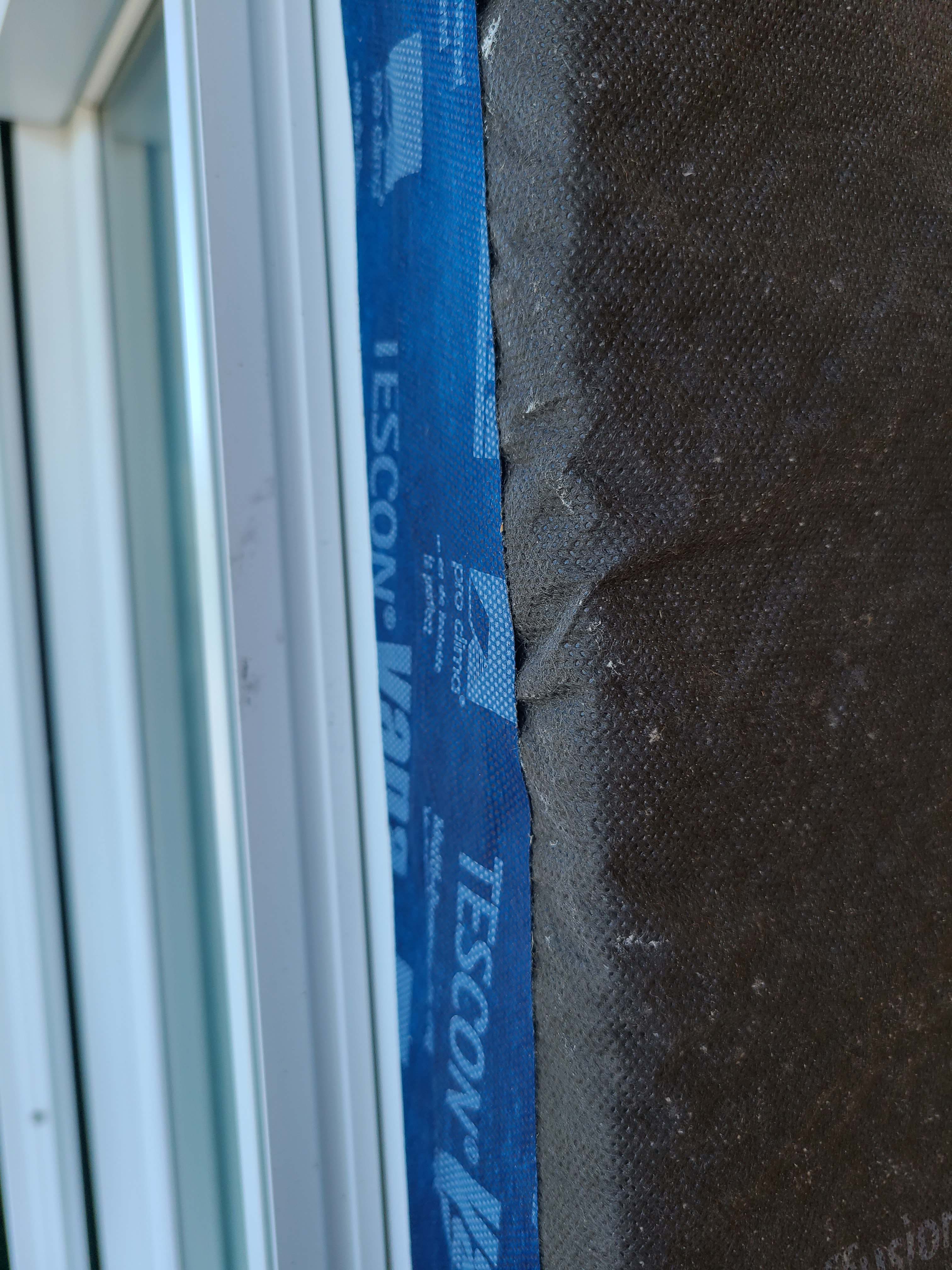
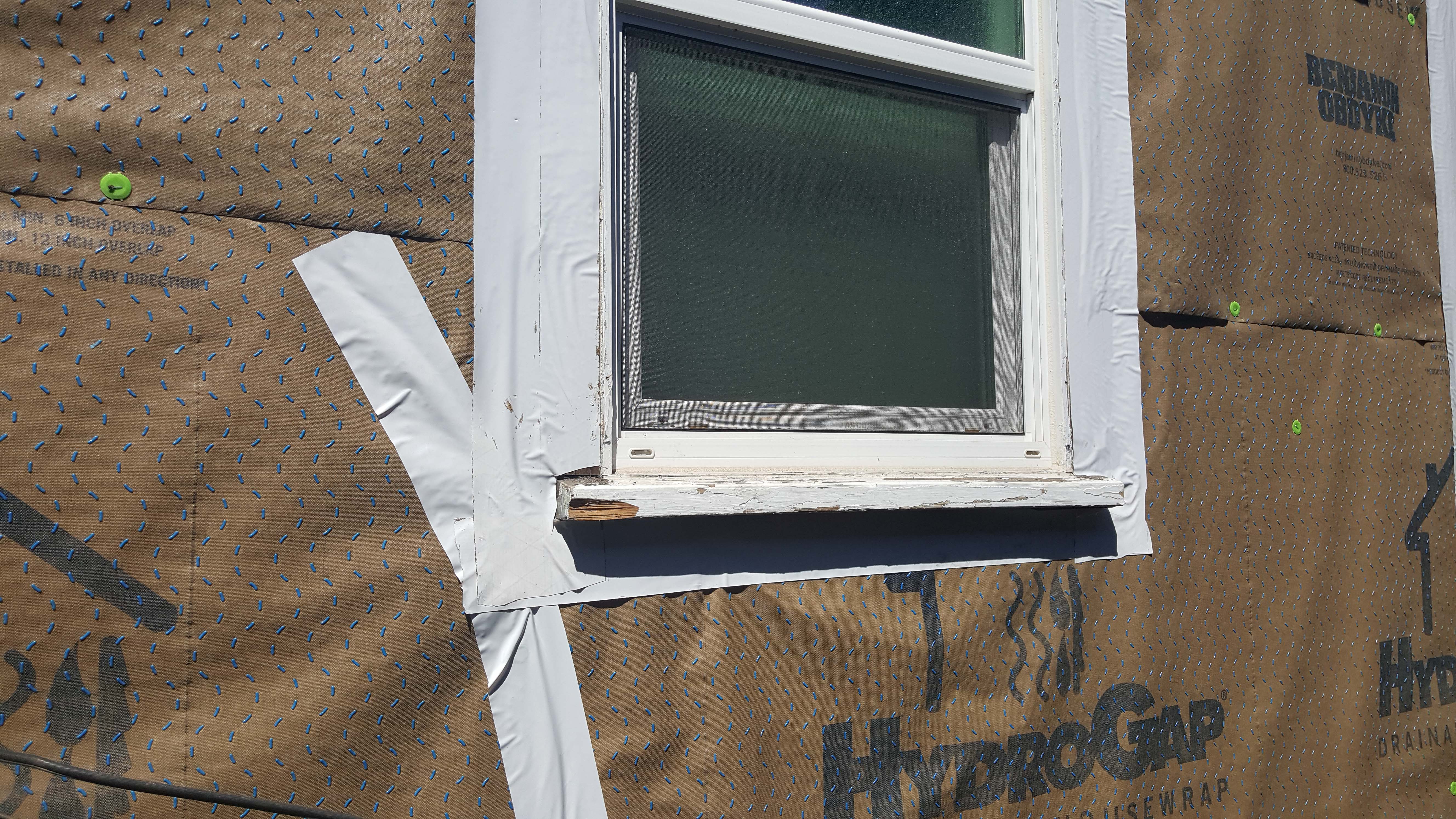
Wrong - House wrap was poorly installed, seams were not taped, and flashing tape was not installed around windows.
Image
Image
Image
Wrong - House wrap and flashing tape are poorly installed allowing water to get into the gaps behind flashing tape.
Image
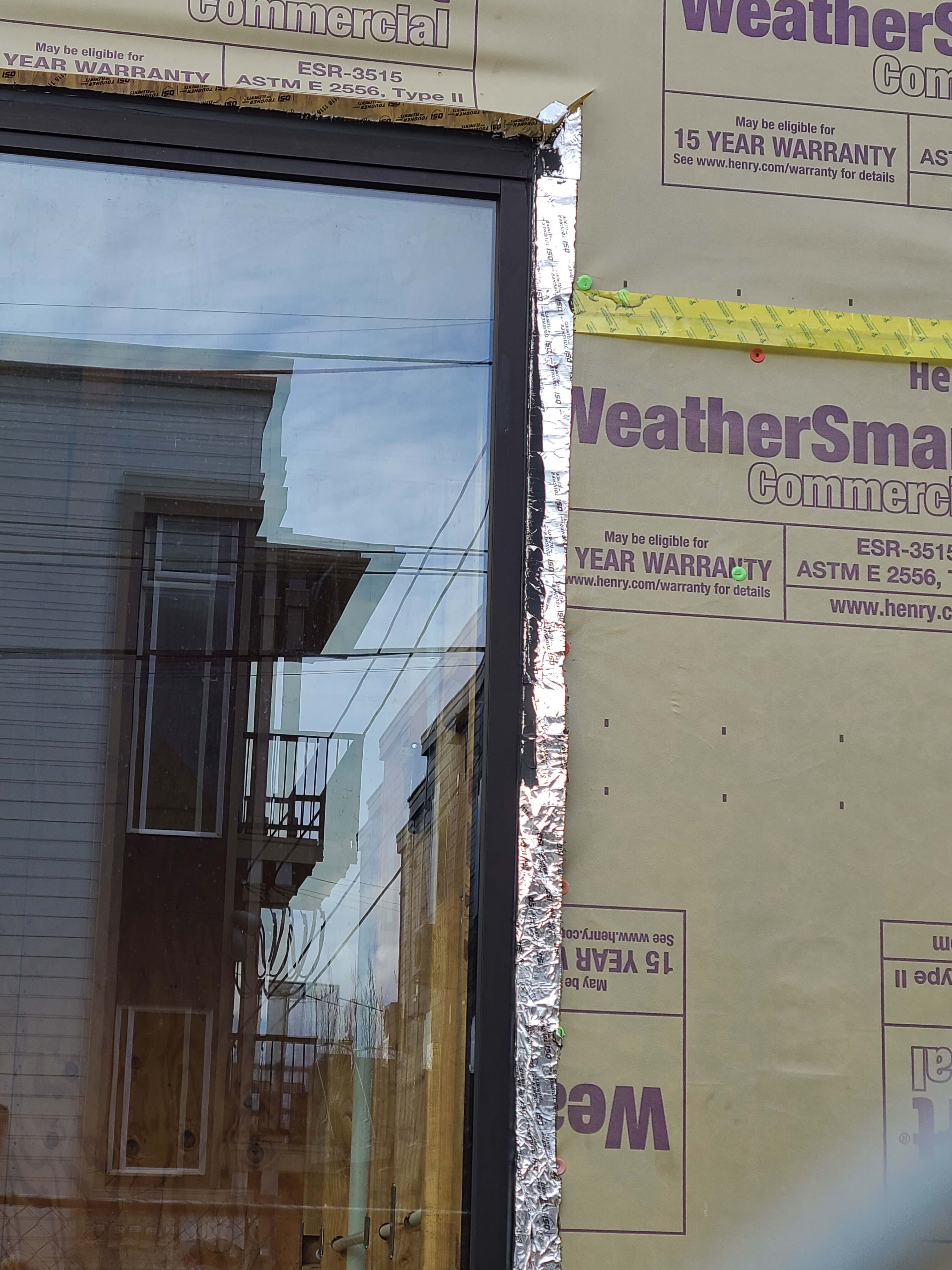
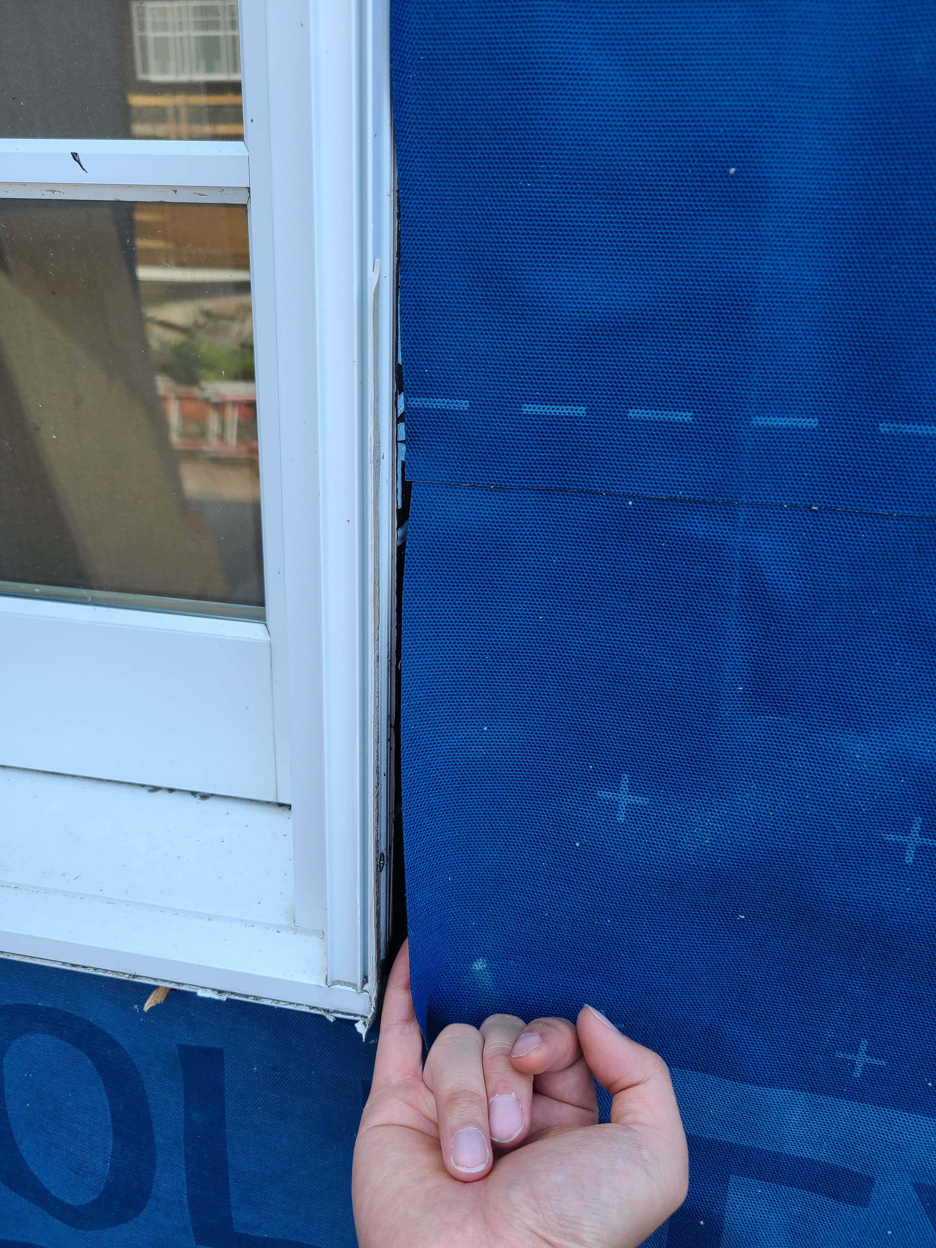
Wrong - House wrap tape is not fully adhered at seam and flashing tape is missing from window head, jamb, and corner above window.
Image
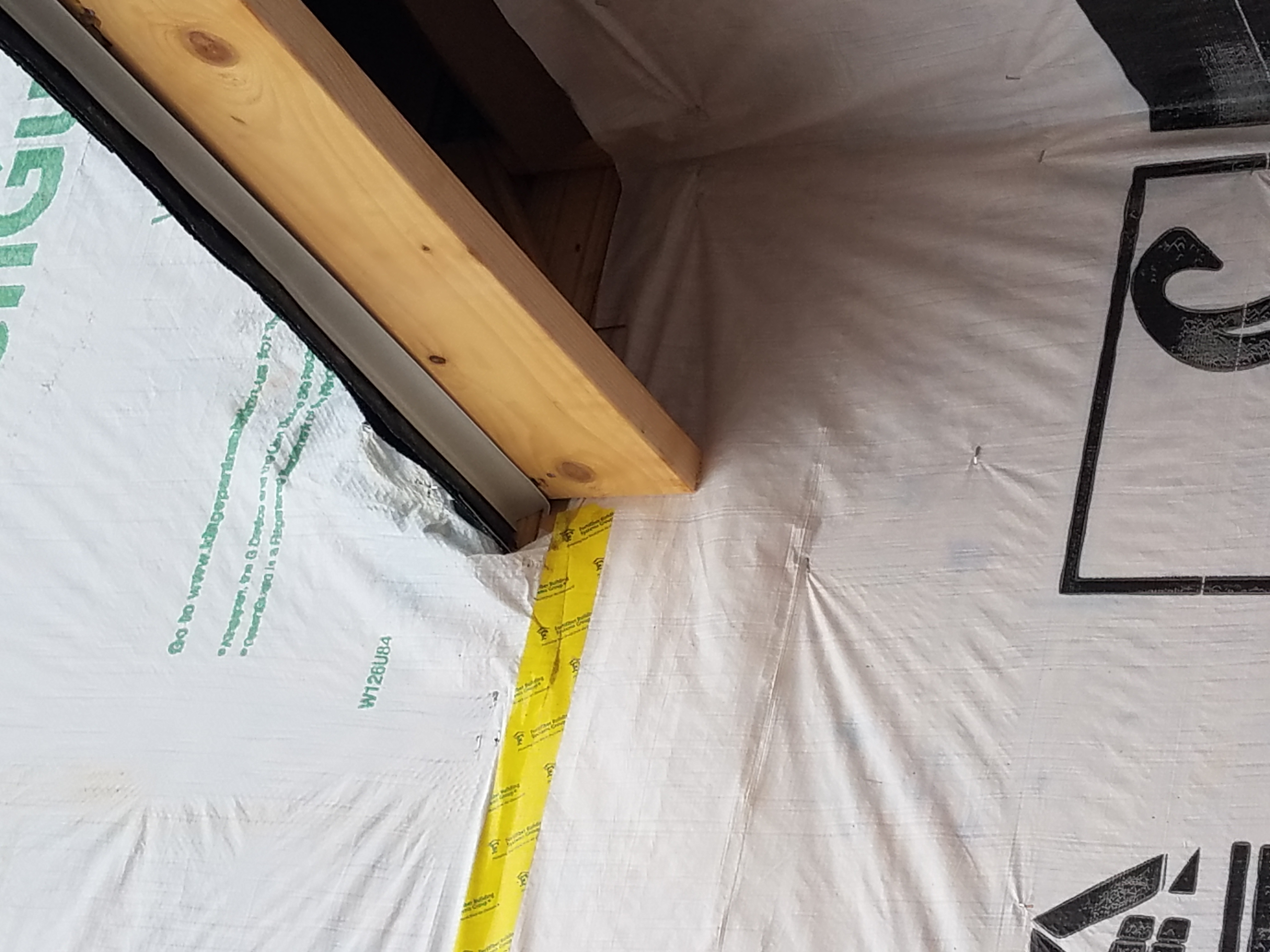
Wrong - House wrap was not properly cut and adhered where the roof meets the wall so water is likely to get behind the house wrap.
Image
Wrong - House wrap was poorly cut at wall interface and not taped leaving wood exposed and vulnerable to water entry.
Image
Wrong - Metal flashing is bent and poorly installed and tape flashing is missing.
Image
Image

Wrong - Missing kick-out flashing to divert rainwater runoff away from the house and into the gutter where the roof meets the wall has caused discoloration of the stucco and water damage behind the stucco by the front porch and the second-story window.
Image
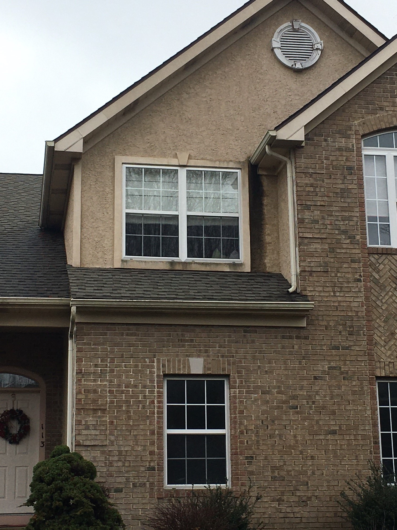
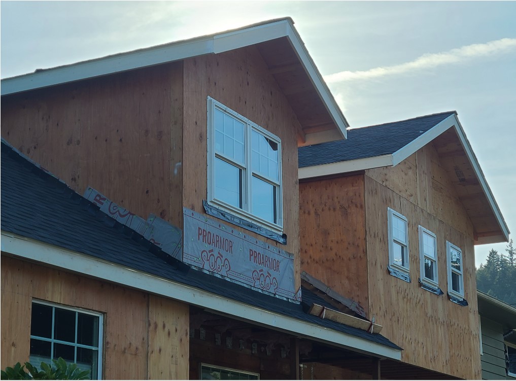
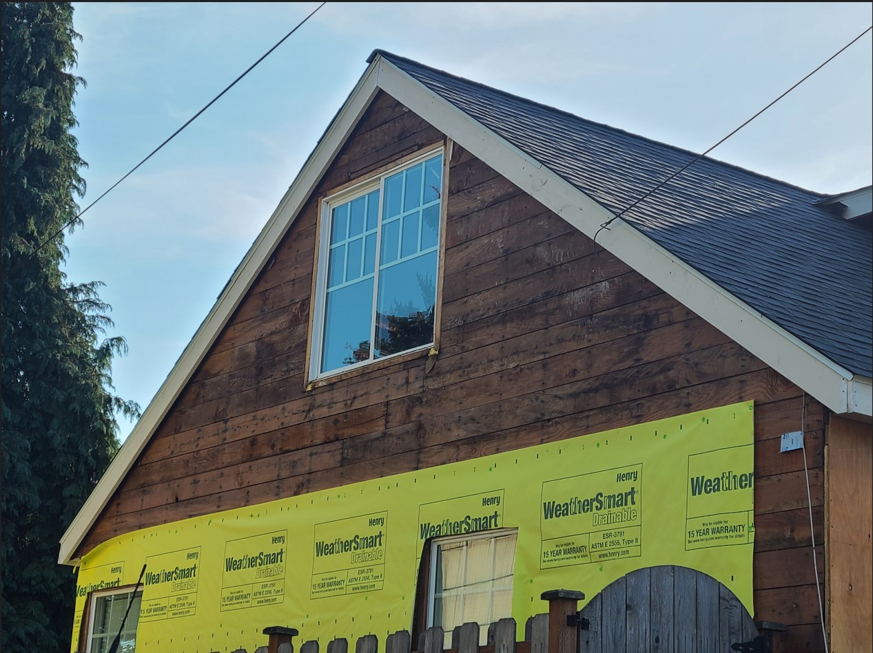
Wrong - Missing kick-out flashing to divert rainwater runoff into the gutter where the roof meets the wall has caused discoloration and water damage behind the stucco next to this second-story window.
Image
Image
Image
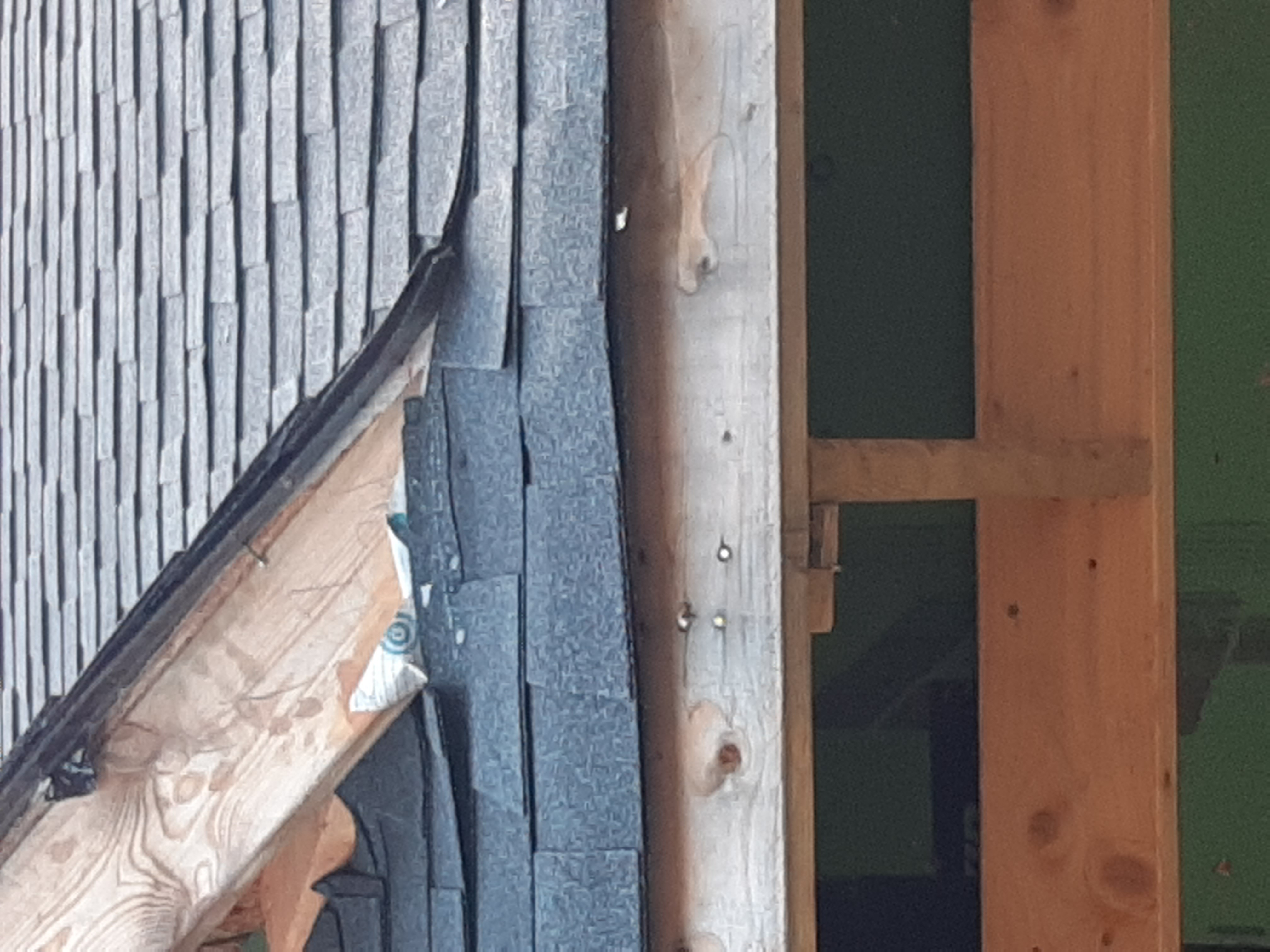
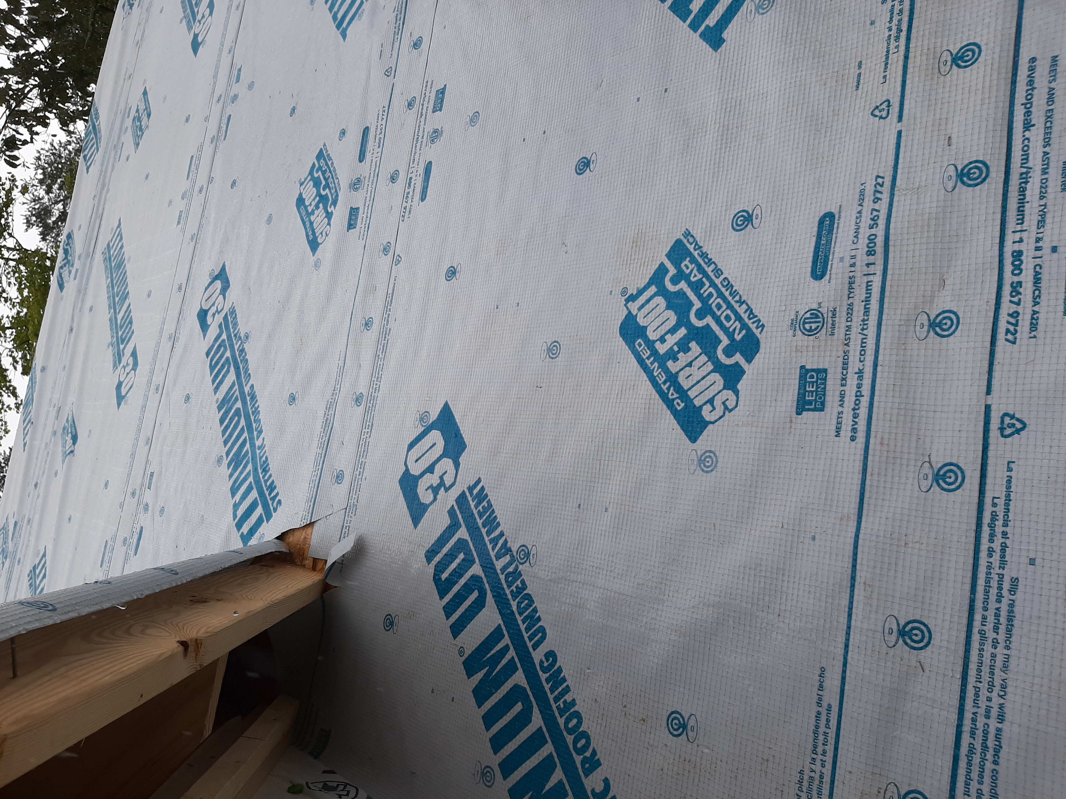
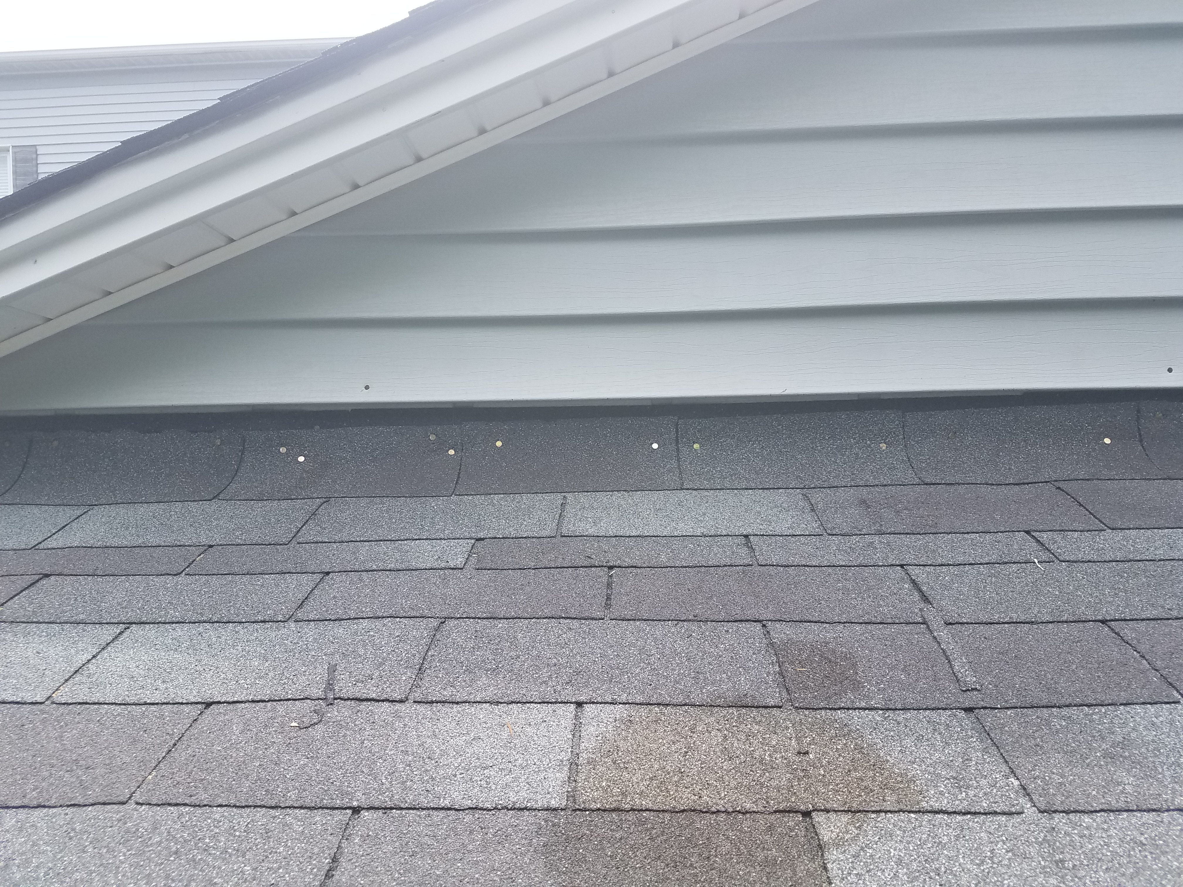
Wrong - Roof is missing metal drip edge to cover the edge of OSB roof decking, roof underlayment should be trimmed back, and asphalt shingles are poorly installed.
Image
Wrong - Roof-wall juncture lacks metal flashing and is poorly designed, thus encouraging water entry.
Image
Wrong - Step flashing is missing where the gable meets roof and the valley flashing is incorrectly on top of rather than under shingles.
Image
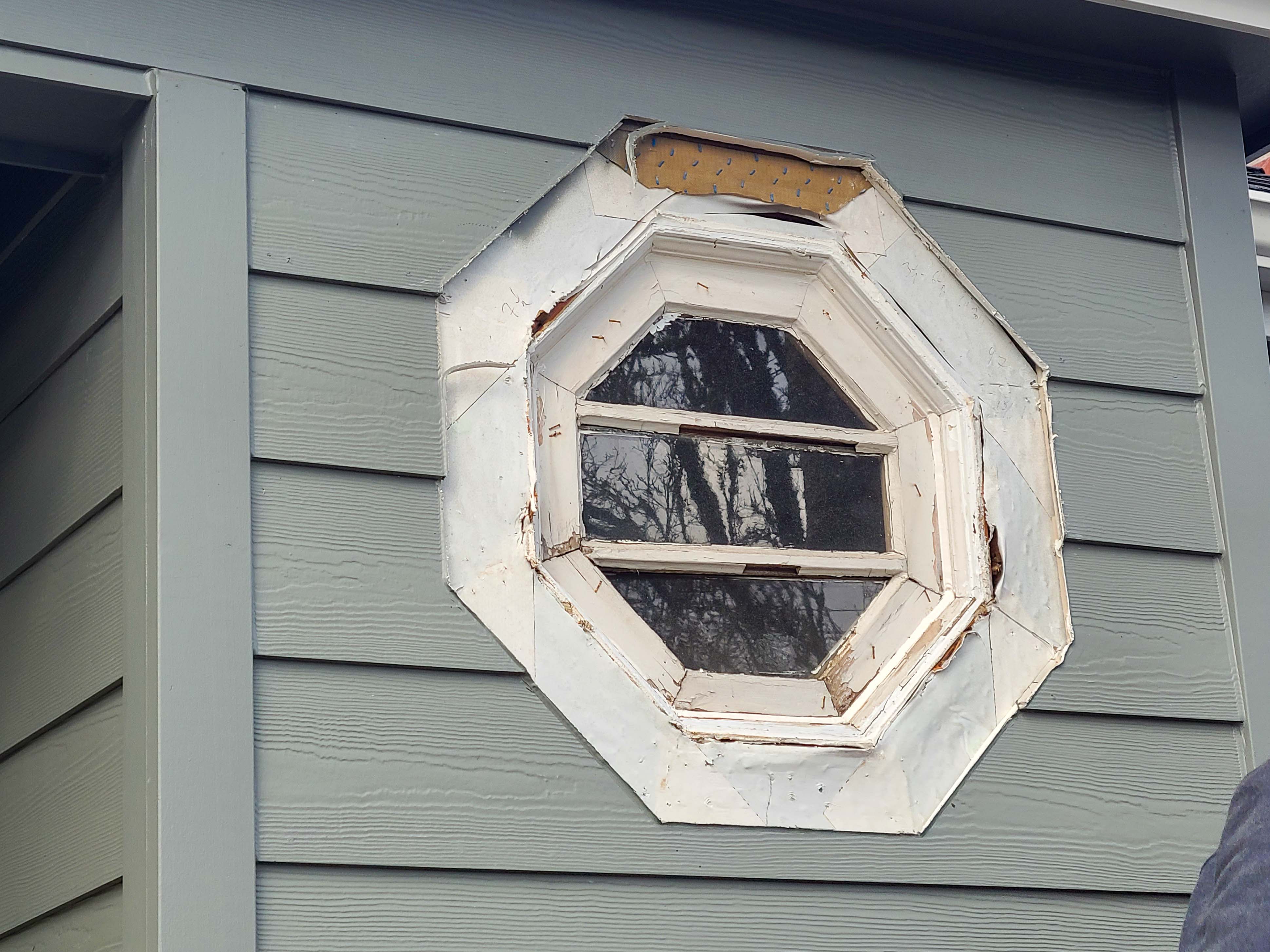
Wrong - Stucco has rotted and cracked above a window because of water damage due to lack of proper flashing and drainage.
Image
Image
Image
Image

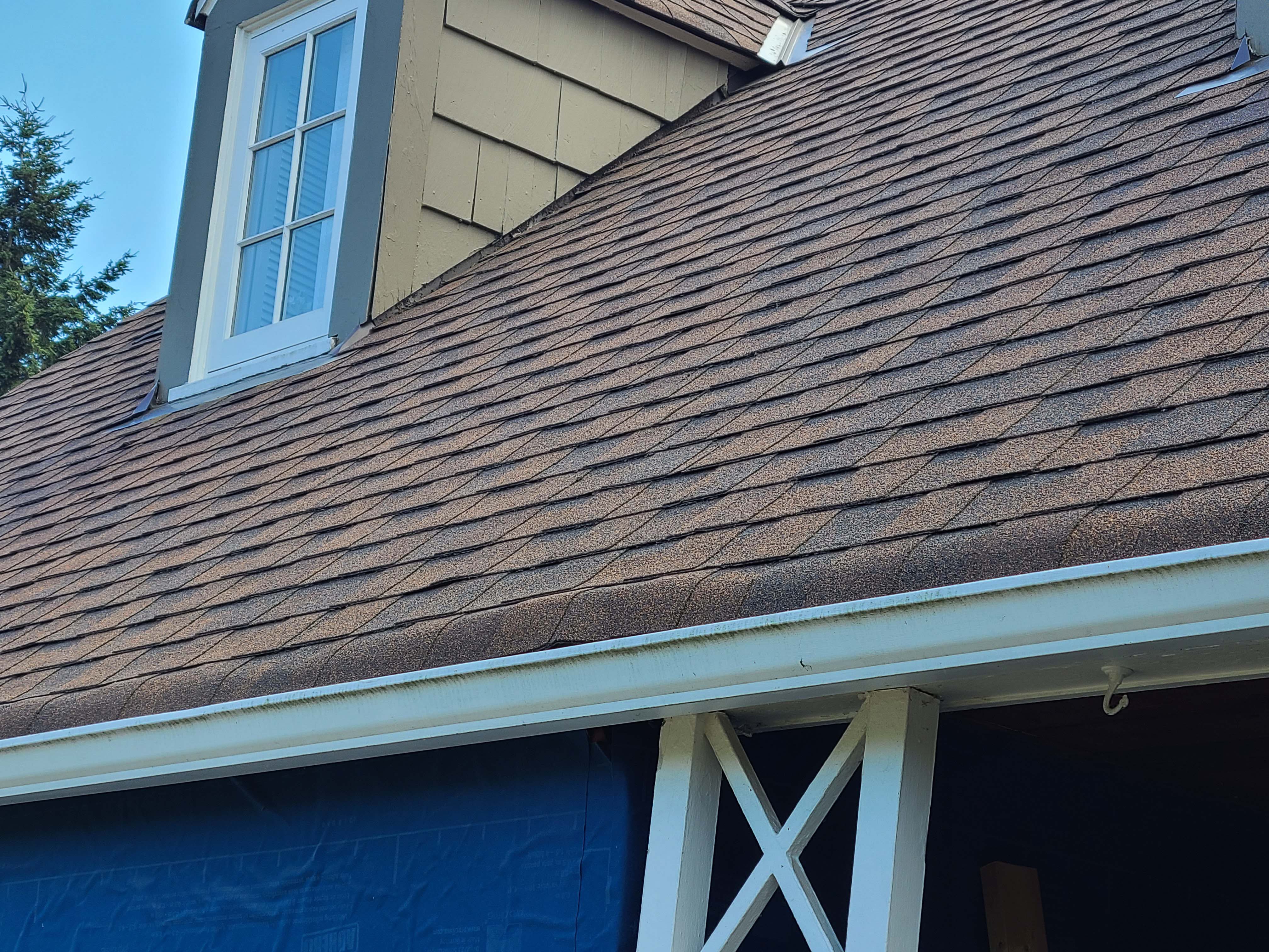
Wrong - The gutter is missing kick-out flashing causing wall and window damage beneath it.
Image

Wrong - The siding on the chimney is rotten because there is no metal step flashing at the base of the chimney.
Image

Image
Image
Image

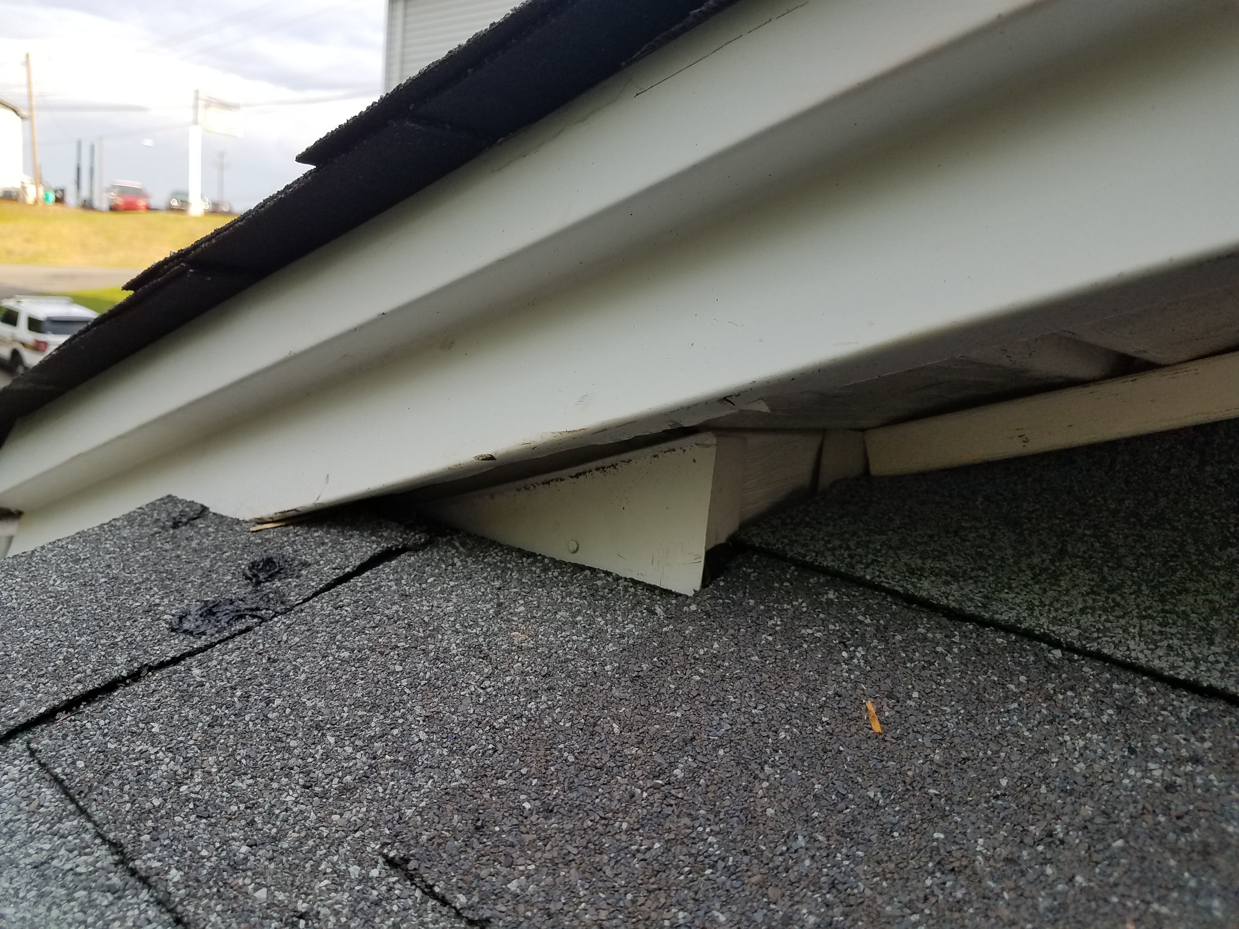
Wrong - There is no step flashing along the base of the gable and the right window is missing sill trim.
Image
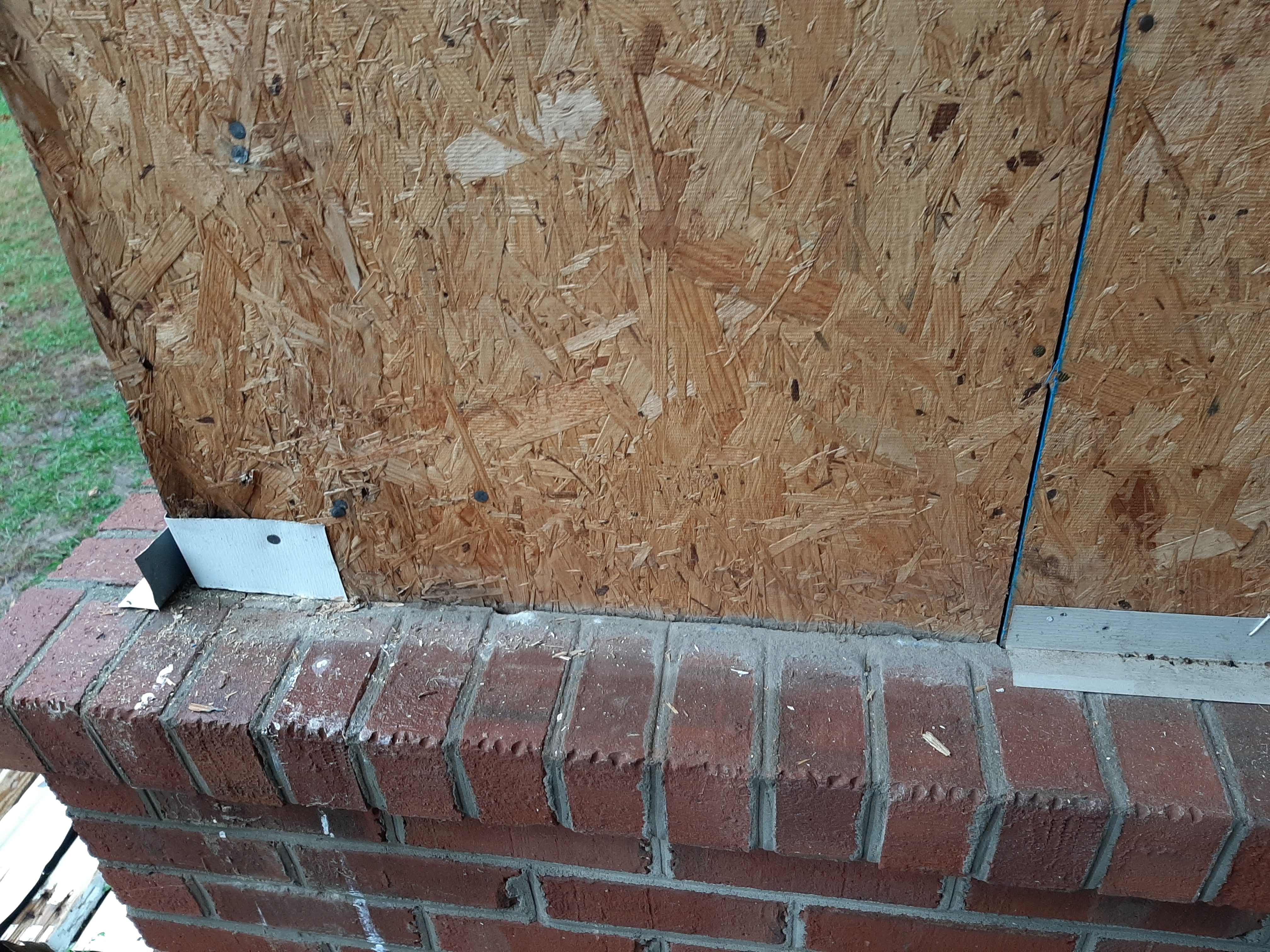
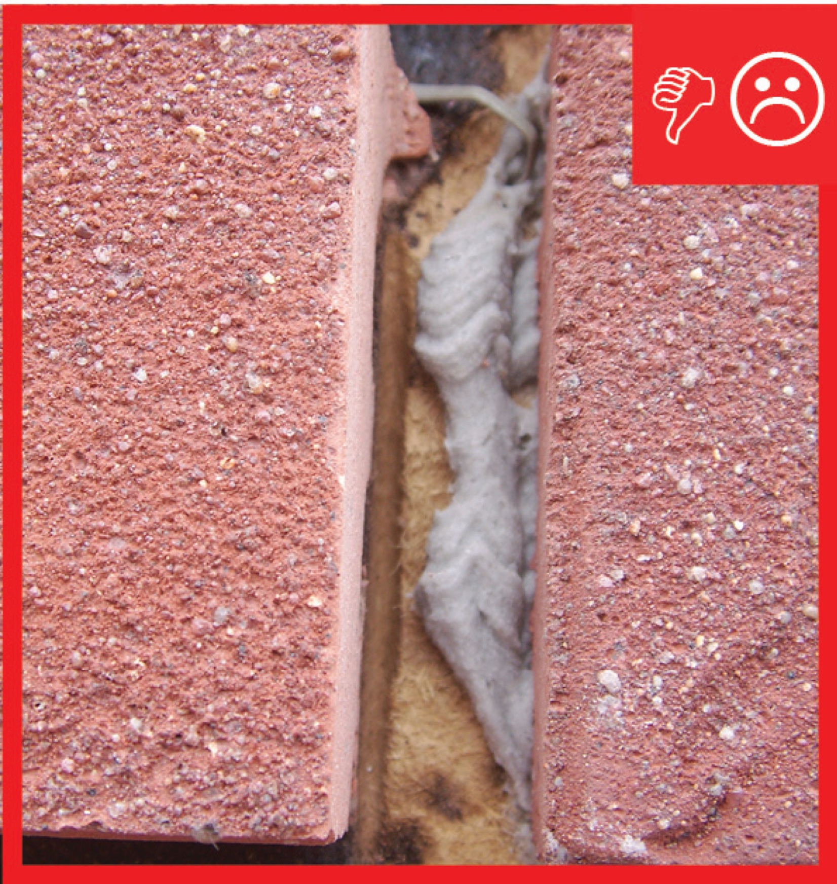
Wrong - Through-wall flashing has not been installed at brick wall intervals and house wrap is missing.
Image
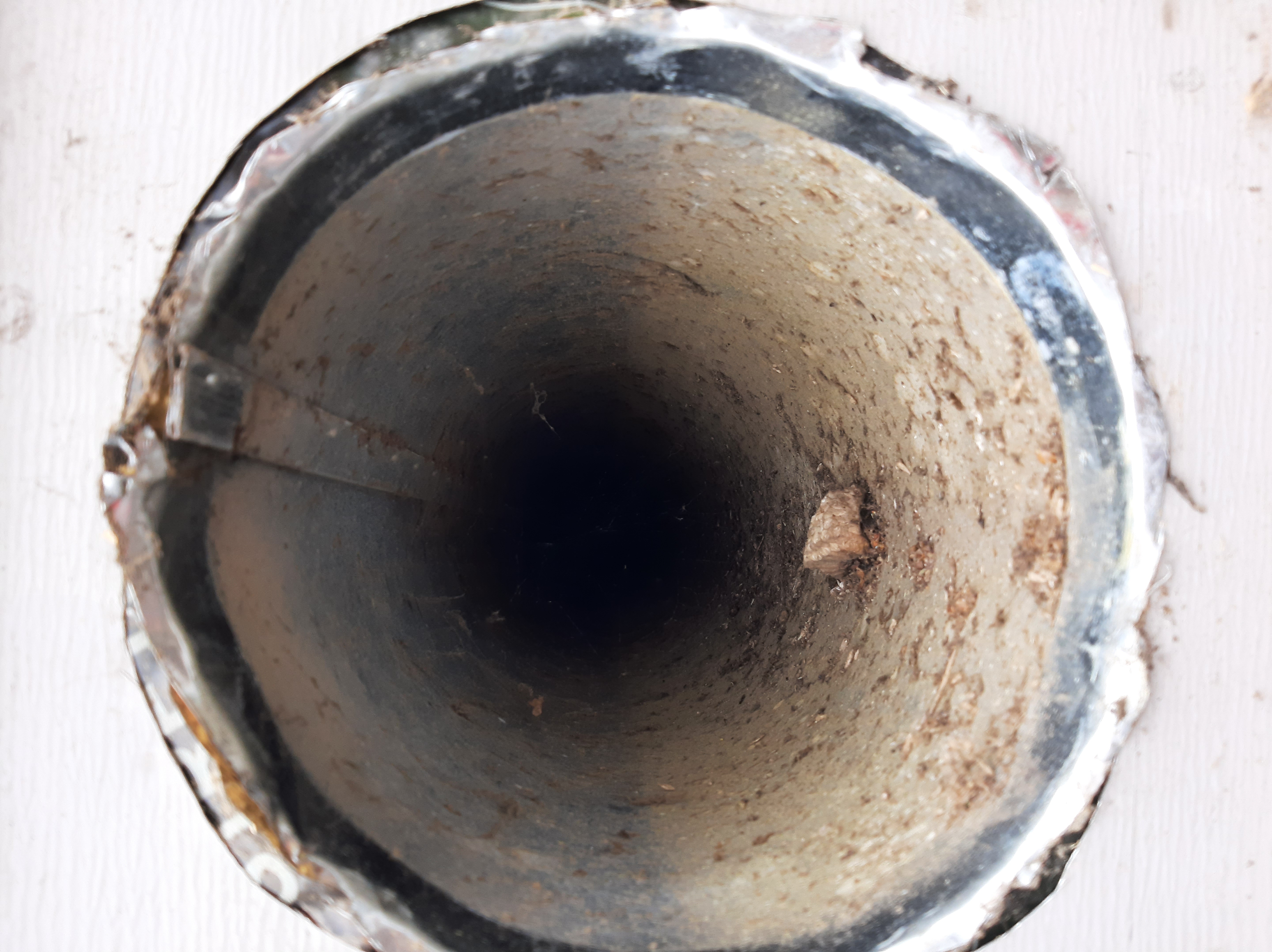
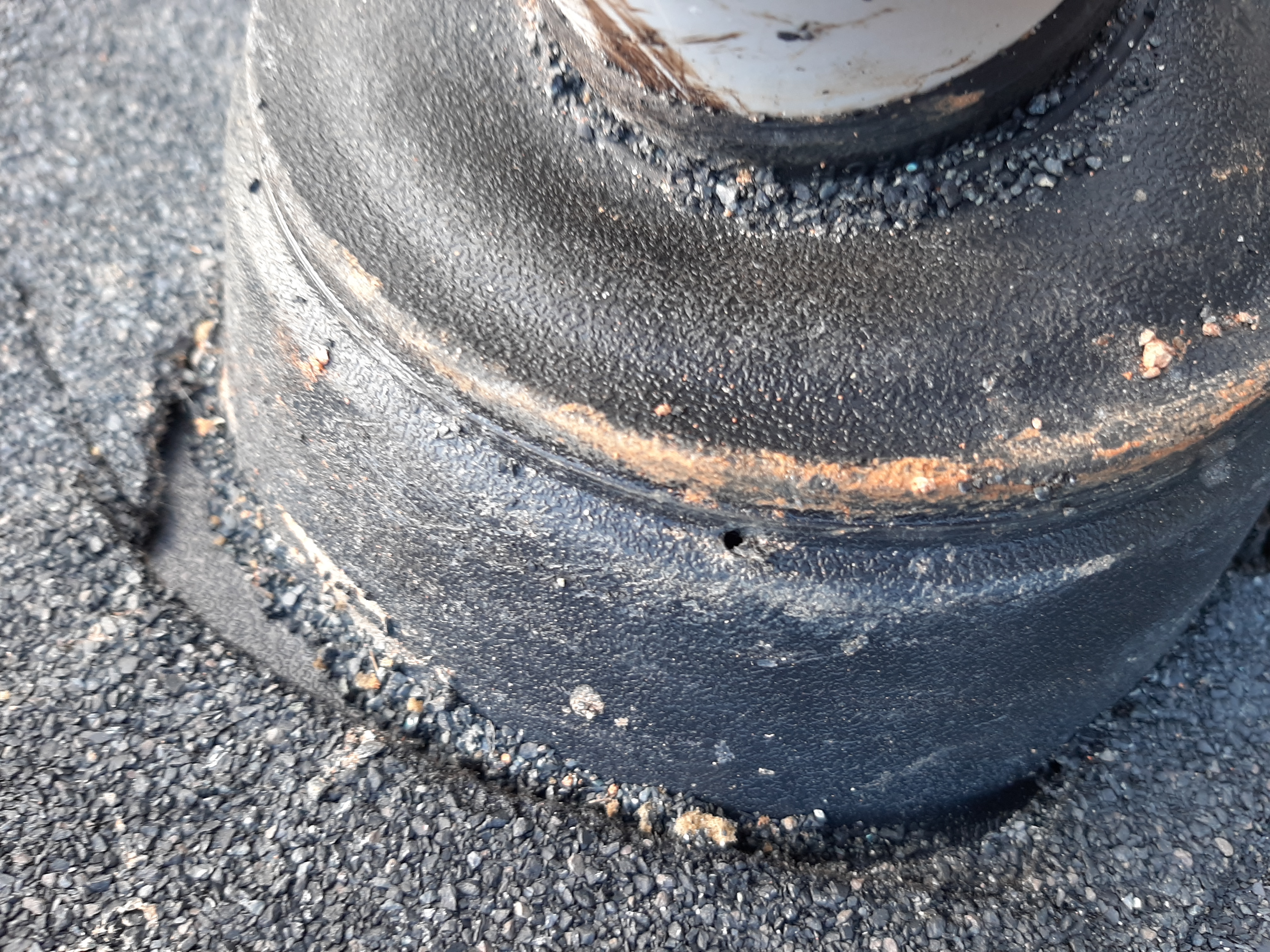
Wrong - Vent hole has no cover or screening and is poorly sealed and flashed to siding.
Image

Wrong - Vent hole has no cover or screening and is poorly sealed and flashed to siding.
Image
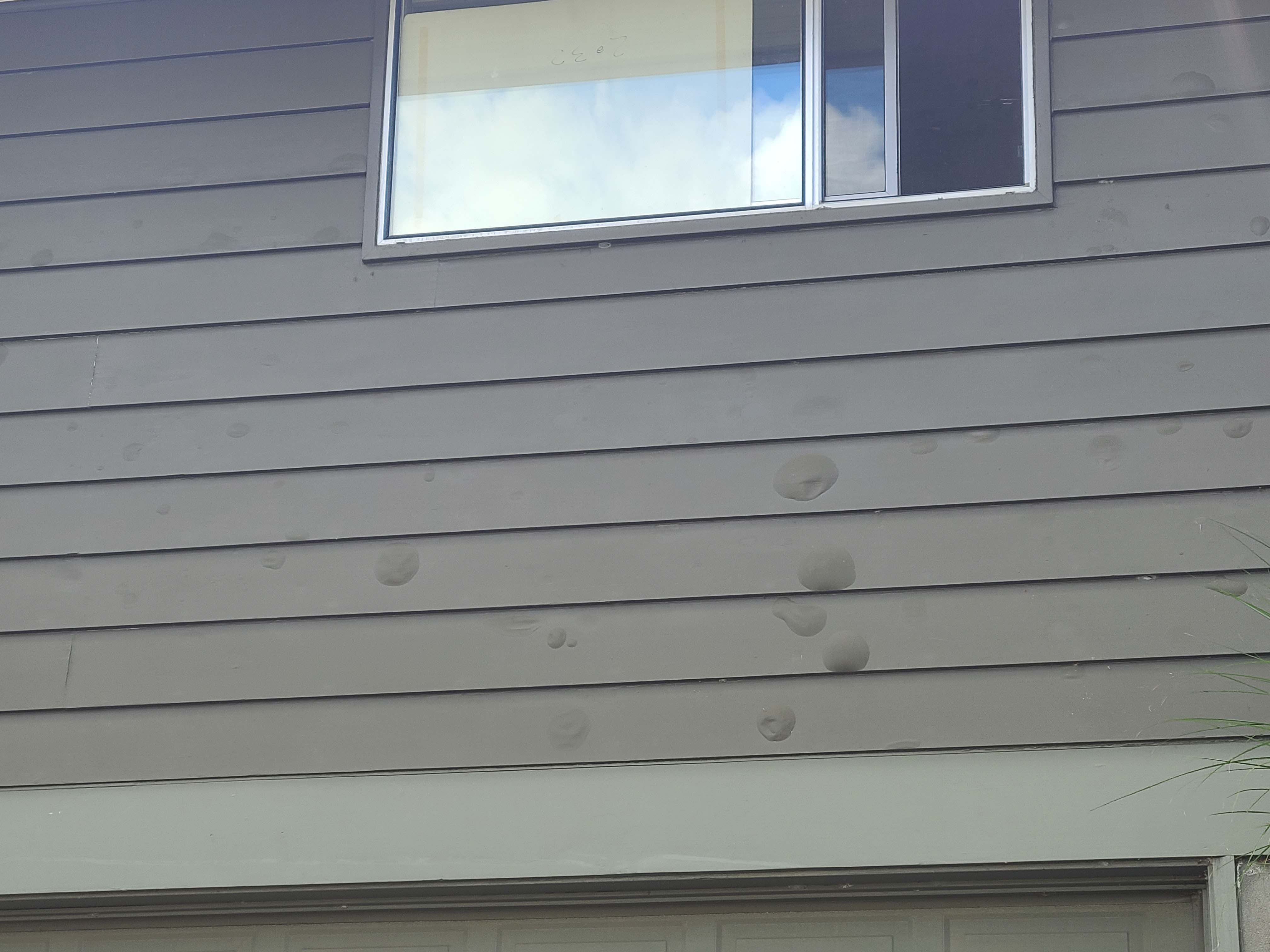
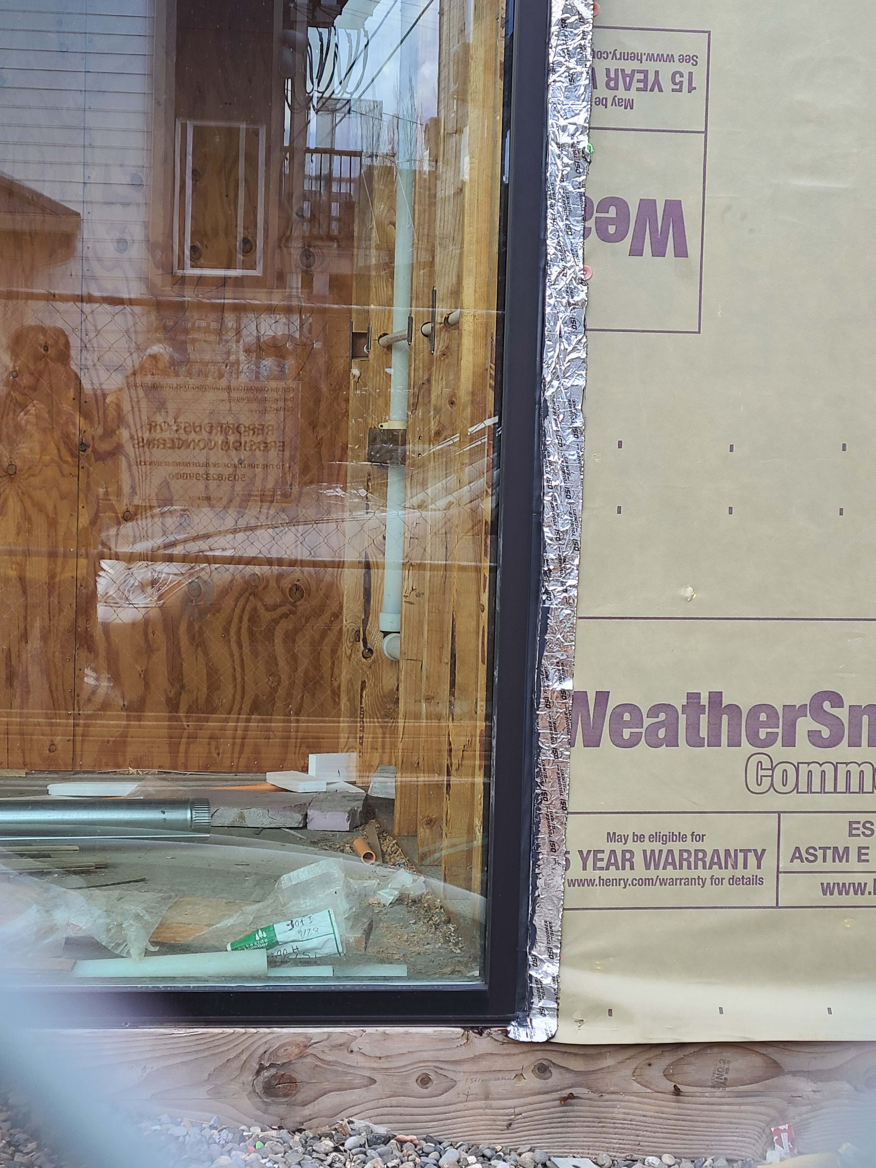
Wrong - Water has gotten behind the paint, possibly due to lack of window flashing, leading to blistering.