Showing results 101 - 146 of 146
Image
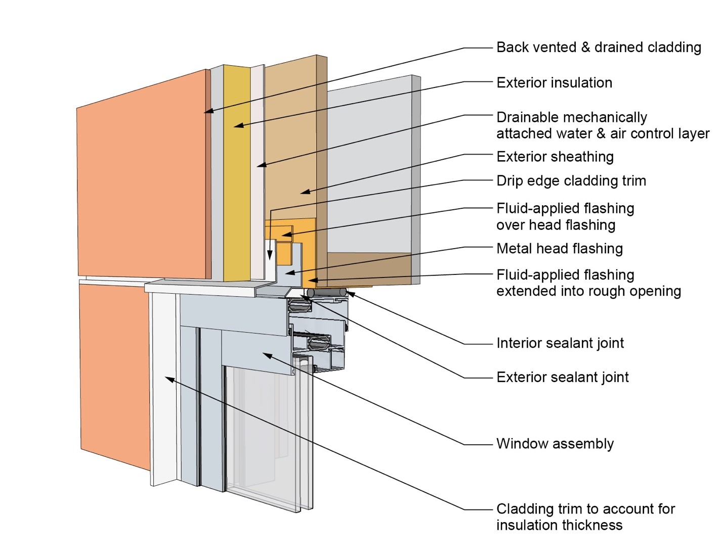
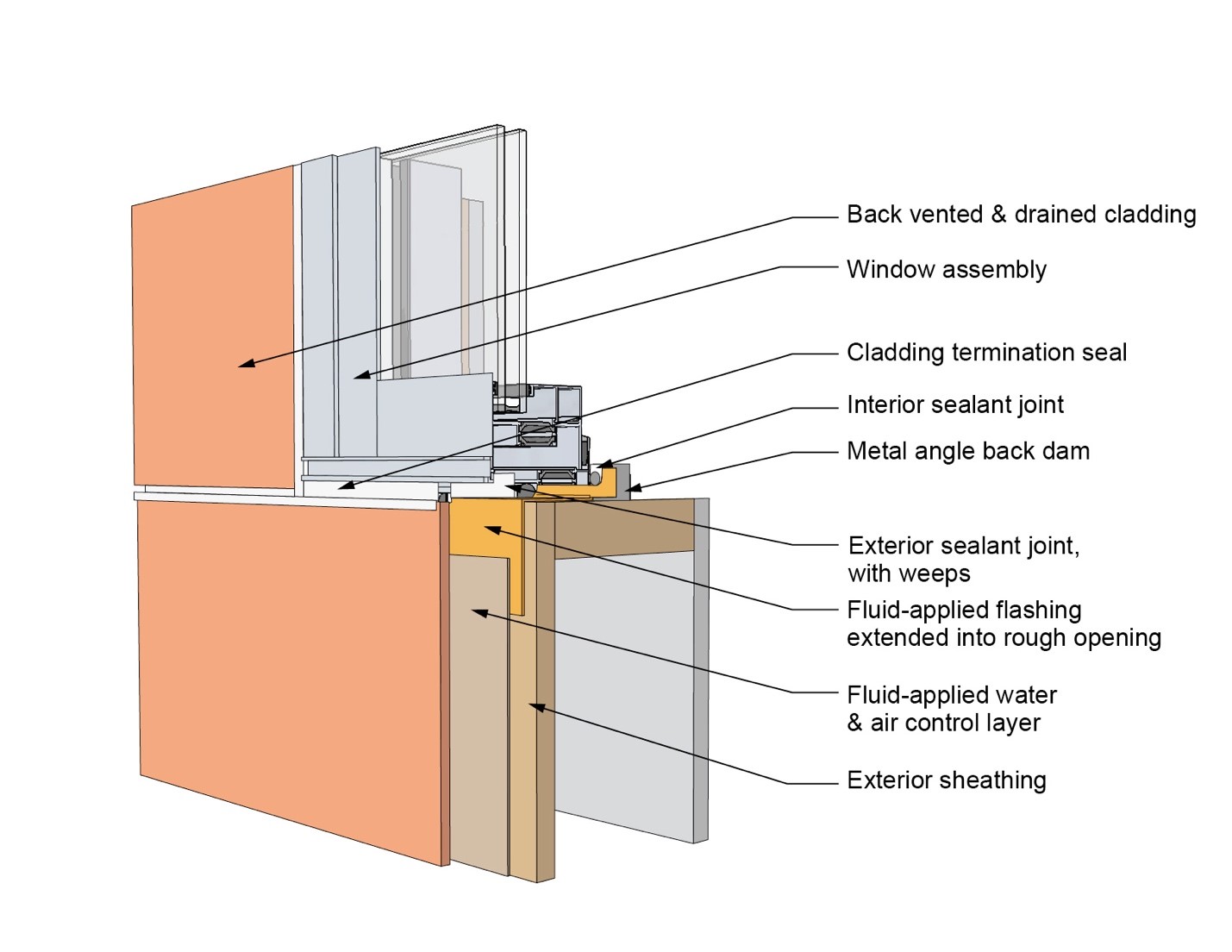
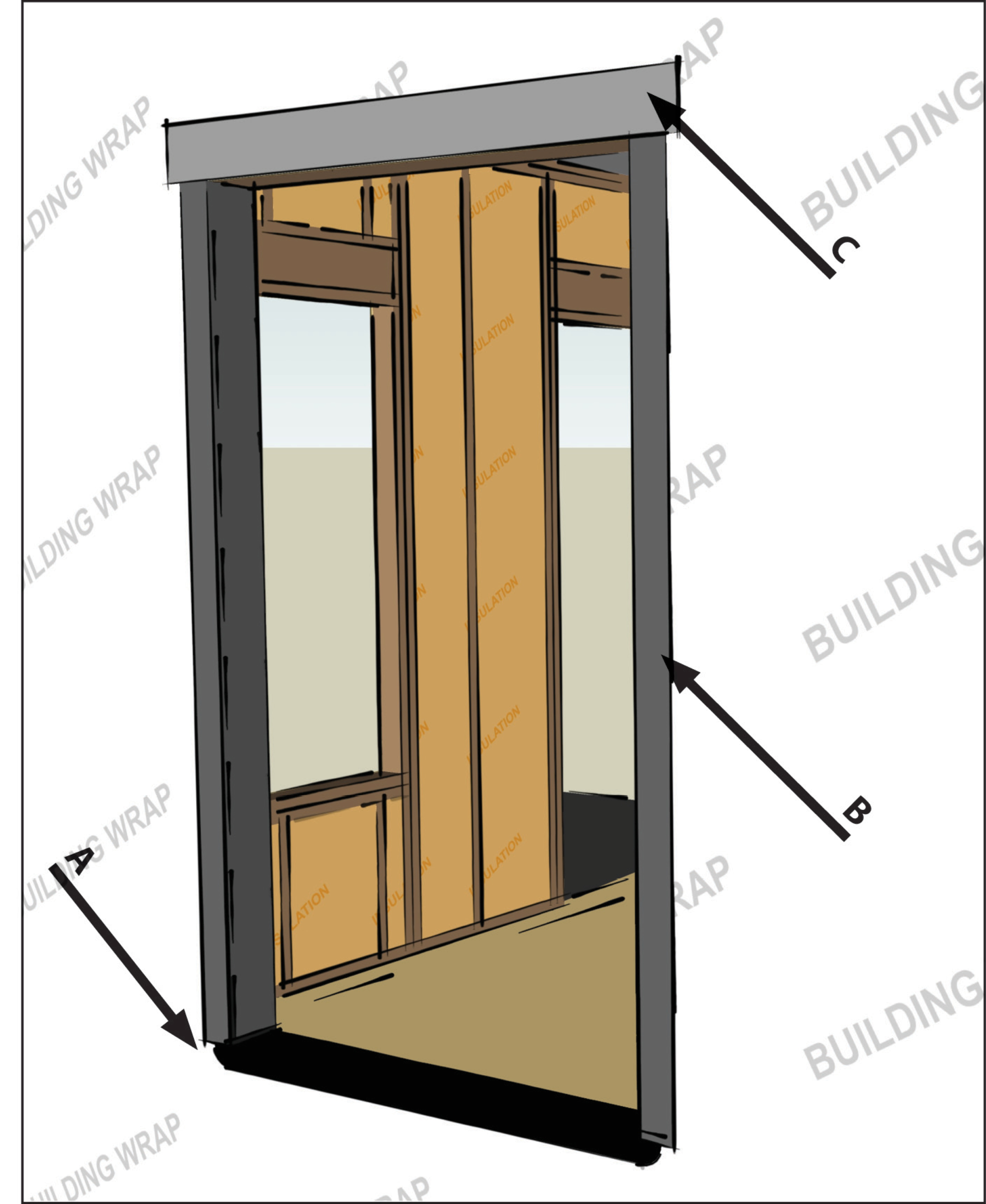
This drawing shows key head details for a window installation using a fluid-applied flashing on a wall with a mechanically attached water and air control layer and continuous insulation
Image
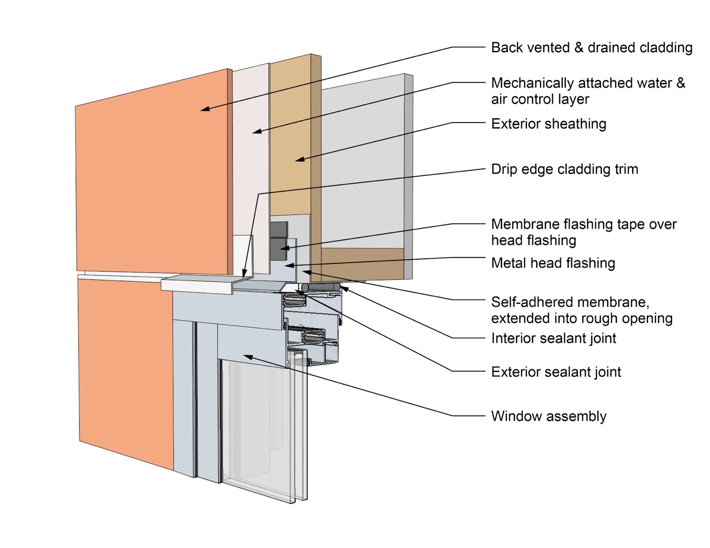
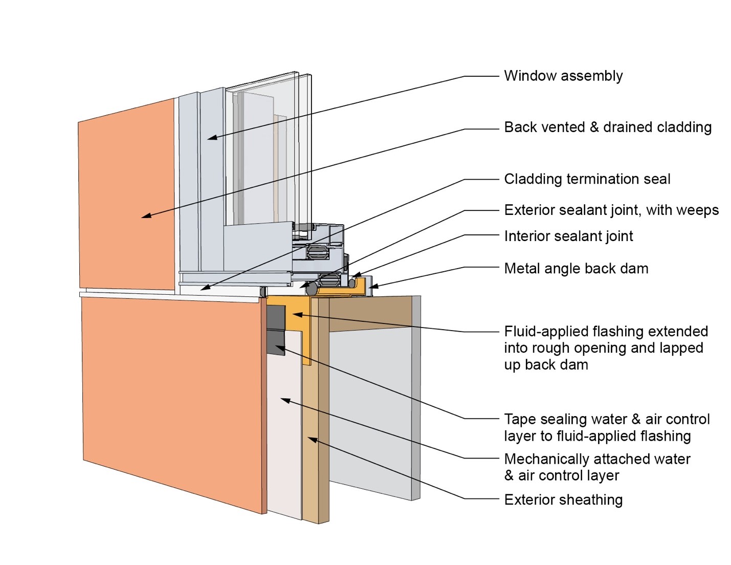
This drawing shows key head details for a window installation using a self-adhered membrane tape flashing on a wall with a mechanically attached water and air control layer
Image
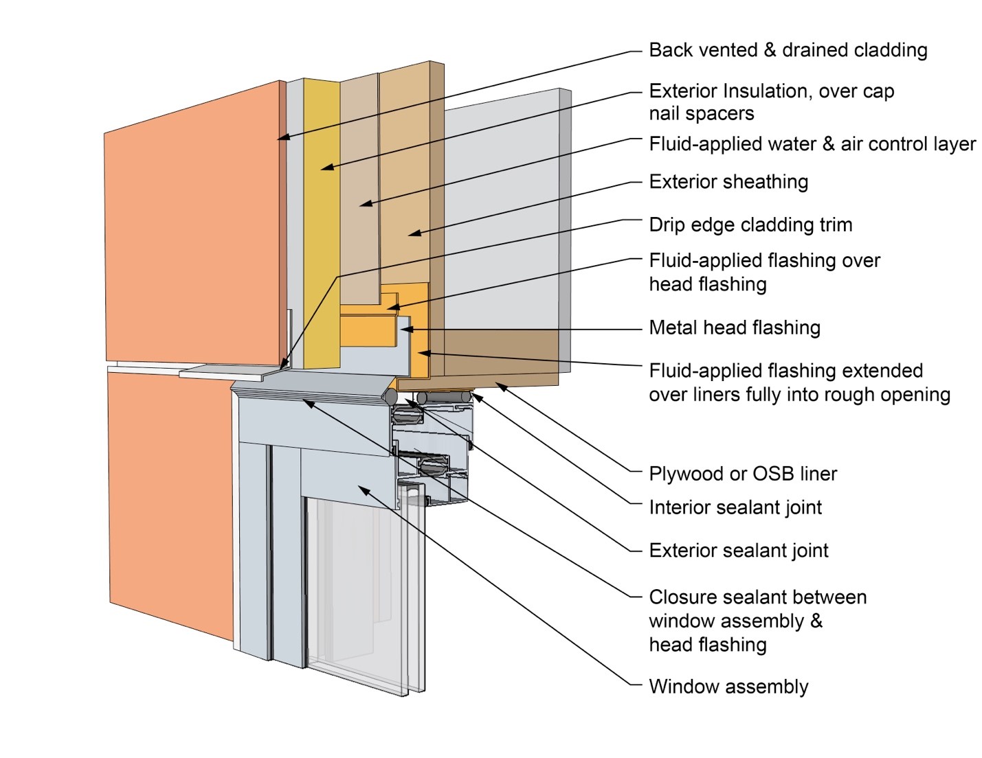
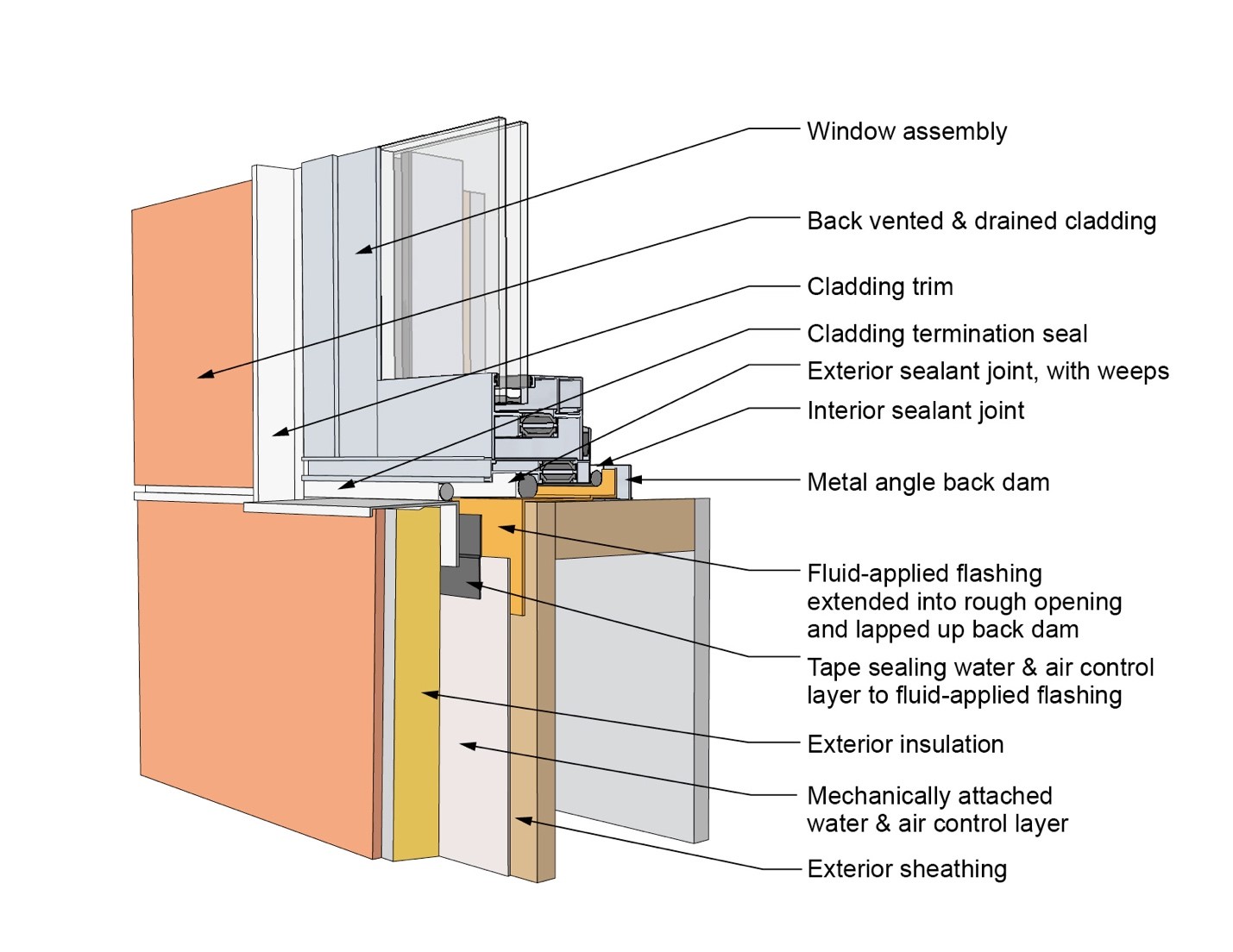
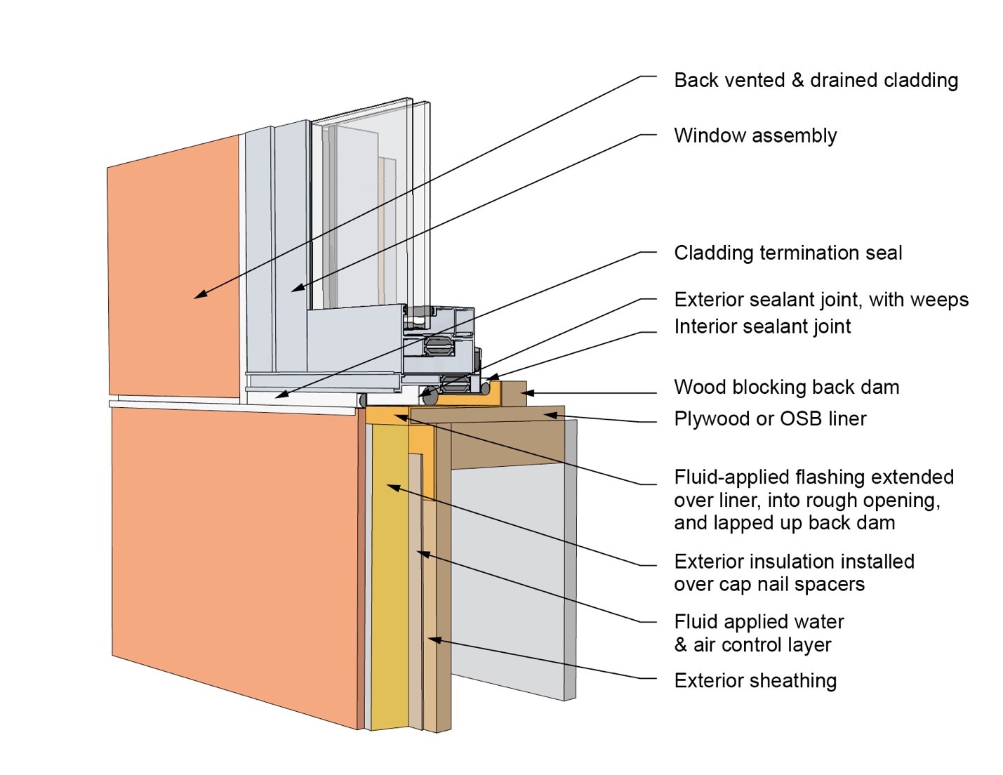
This drawing shows key head details for an “outie” window installation using a fluid-applied flashing on a wall with a fluid-applied water and air control layer and continuous insulation
Image
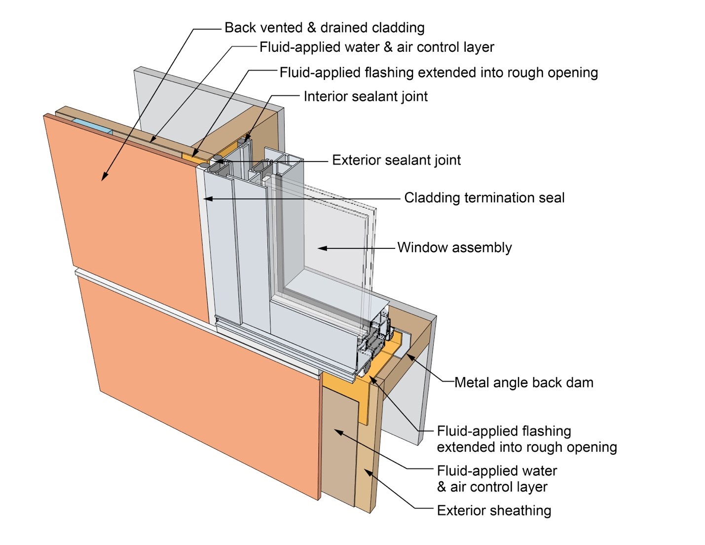
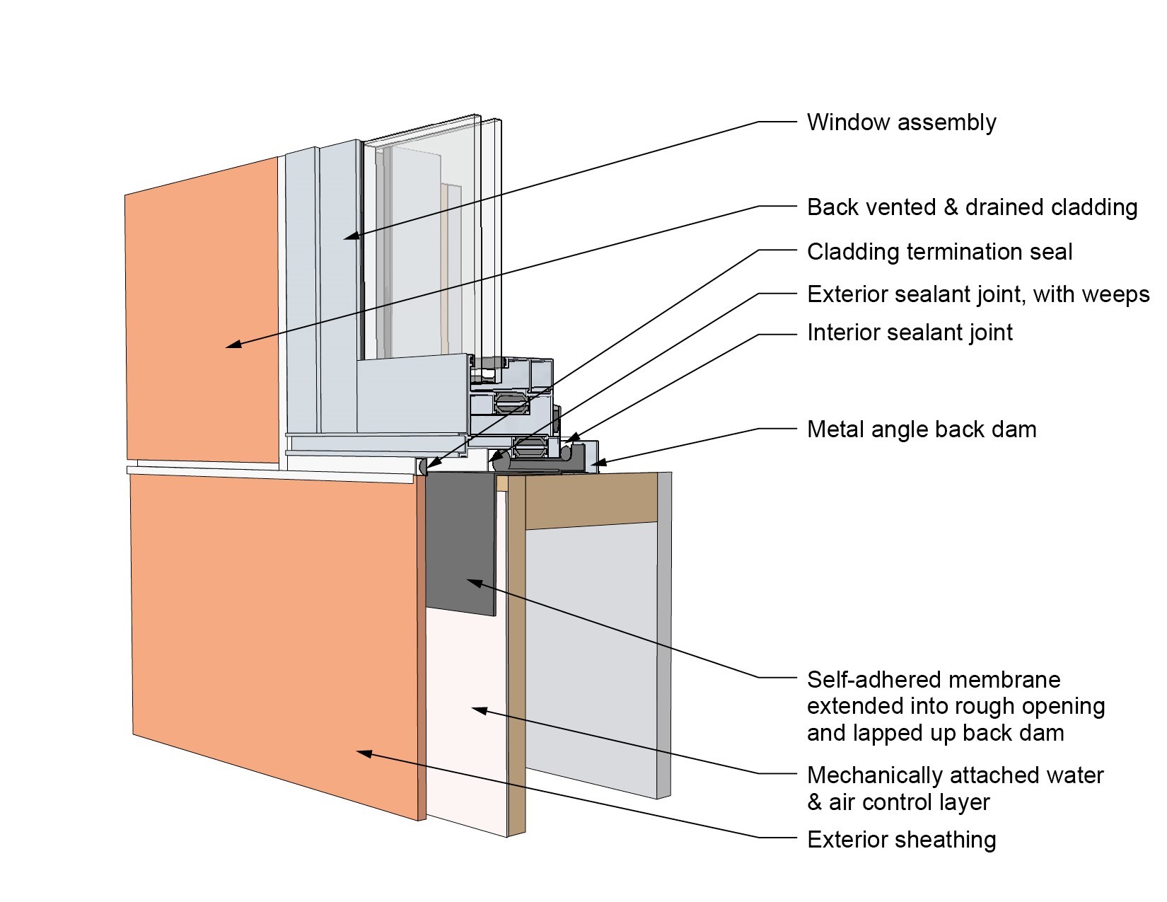
This drawing shows key jamb details for a window installation using a fluid-applied flashing on a wall with a fluid-applied water and air control layer
Image
This drawing shows key jamb details for a window installation using a fluid-applied flashing on a wall with a mechanically attached water and air control layer
Image
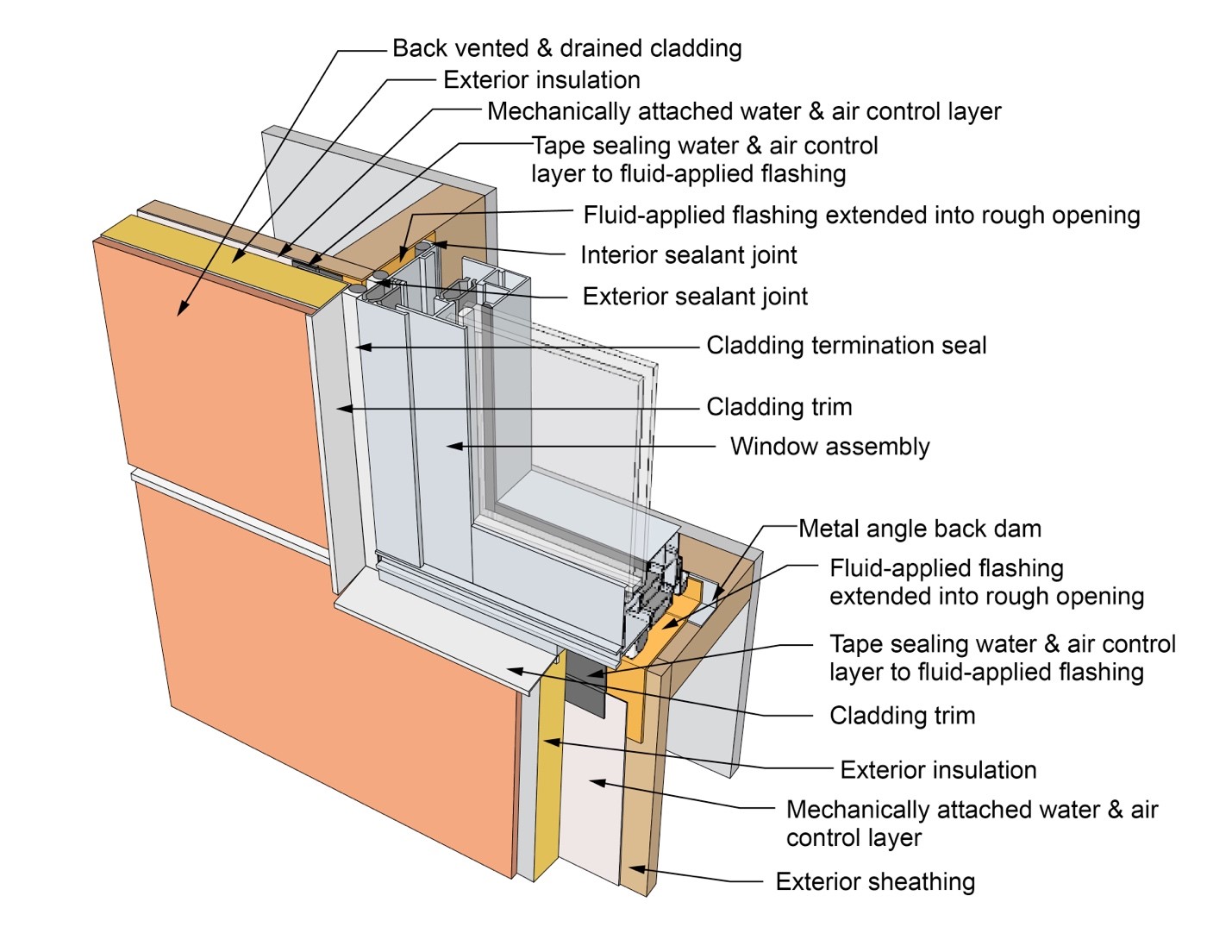
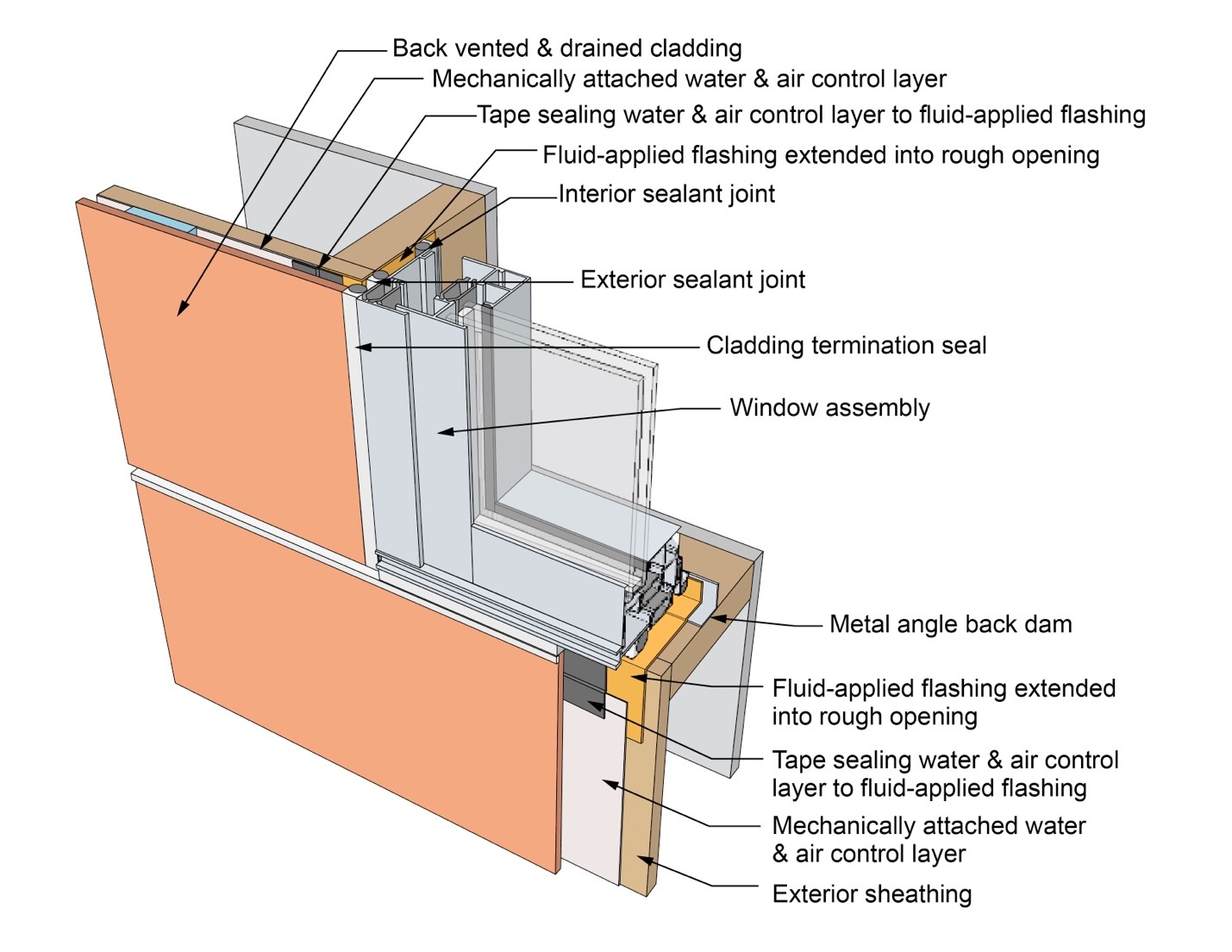
This drawing shows key jamb details for a window installation using a fluid-applied flashing on a wall with a mechanically attached water and air control layer and continuous insulation
Image
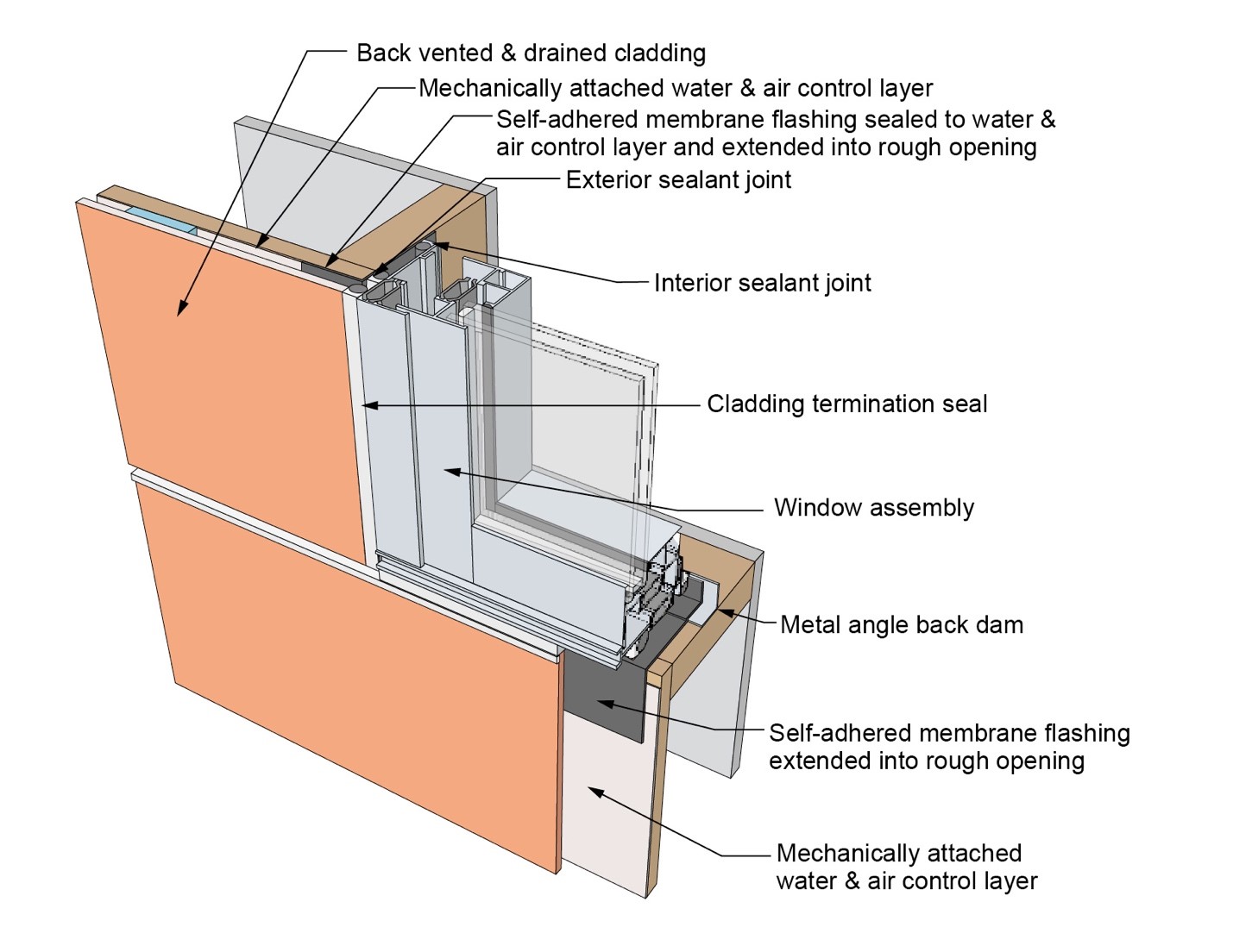
This drawing shows key jamb details for a window installation using a self-adhered membrane tape flashing on a wall with a mechanically attached water and air control layer
Image
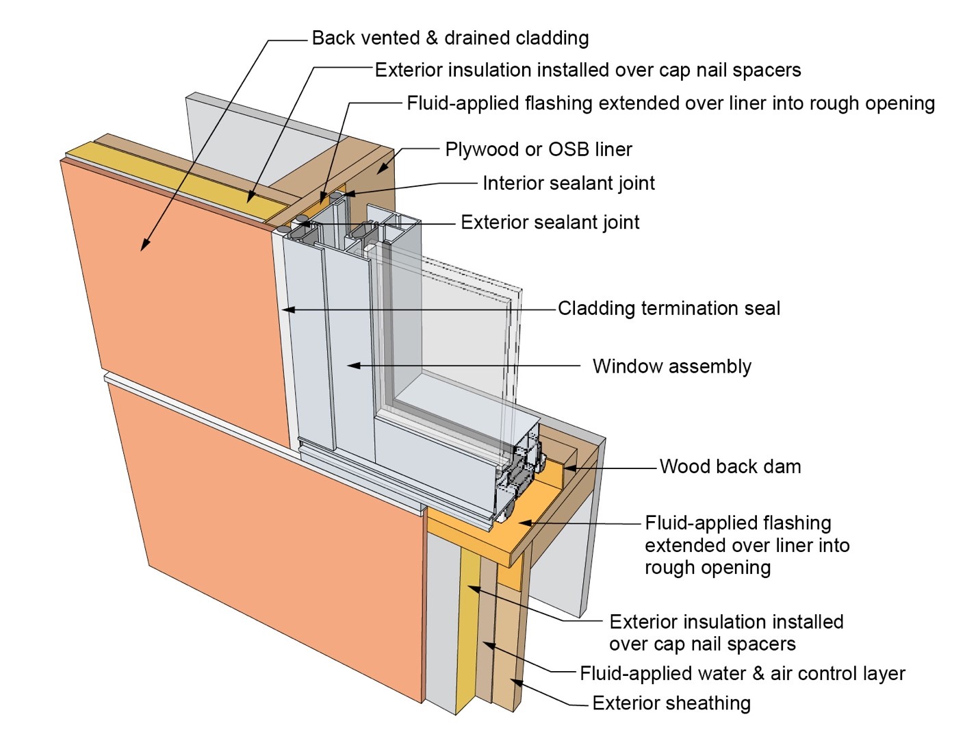
This drawing shows key jamb details for an “outie” window installation using a fluid-applied flashing on a wall with a fluid-applied water and air control layer and continuous insulation
Image
This drawing shows key sill details for a window installation using a fluid-applied flashing on a wall with a fluid-applied water and air control layer
Image
This drawing shows key sill details for a window installation using a fluid-applied flashing on a wall with a mechanically attached water and air control layer
Image
This drawing shows key sill details for a window installation using a fluid-applied flashing on a wall with a mechanically attached water and air control layer and continuous insulation
Image
This drawing shows key sill details for a window installation using a self-adhered membrane tape flashing on a wall with a mechanically attached water and air control layer
Image
This drawing shows key sill details for an “outie” window installation using a fluid-applied flashing on a wall with a fluid-applied water and air control layer and continuous insulation
Image
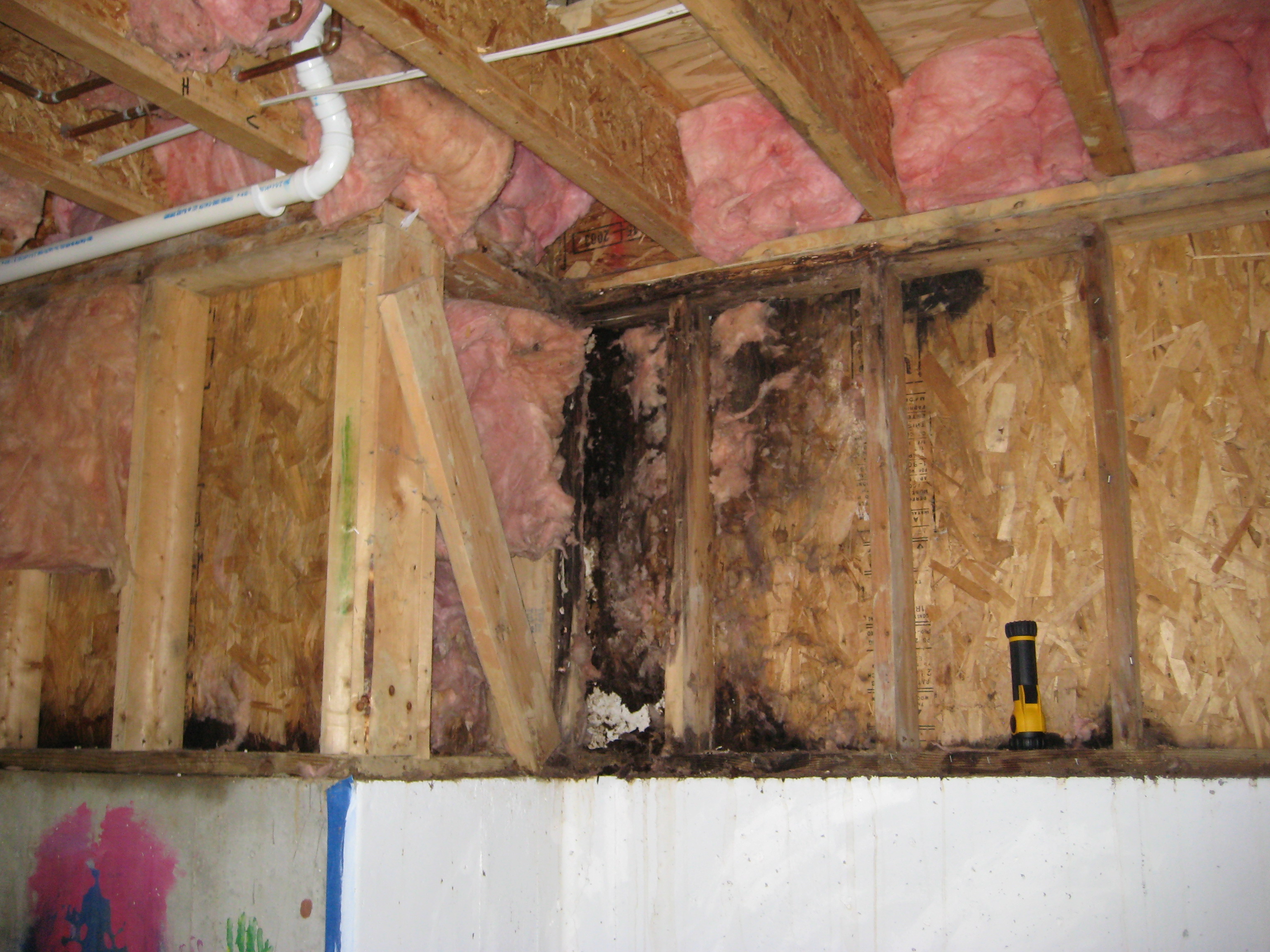
This exterior wall retrofit permits drying to the exterior of a sill plate installed on an untreated flat foundation wall
Image
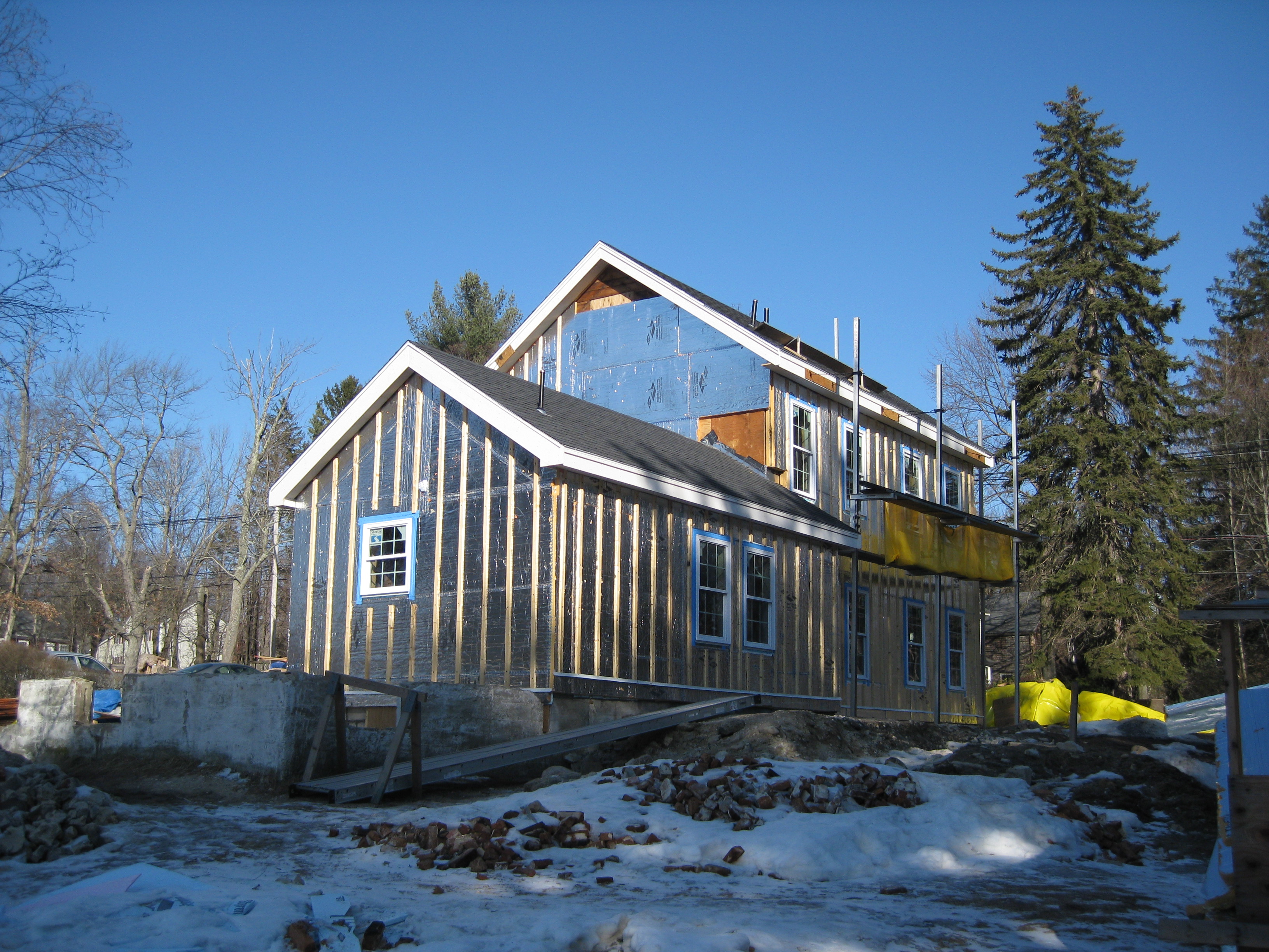
This farmhouse was retrofit by removing the existing siding and adding taped insulated sheathing and battens before installing new siding
Image
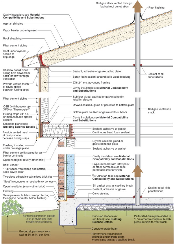
This house design in the Hot-Humid climate uses a slab foundation, masonry walls, and an Exterior Insulation Finish System (EIFS) cladding.
Image
Image
Image

Weep holes: Rope inserted in the head joist between bricks will allow water to weep out of the base of the wall assembly
Image
Image

Image
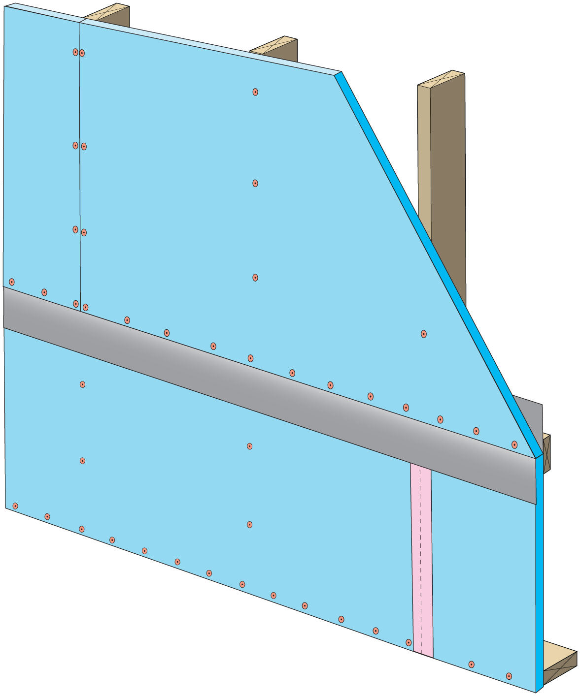
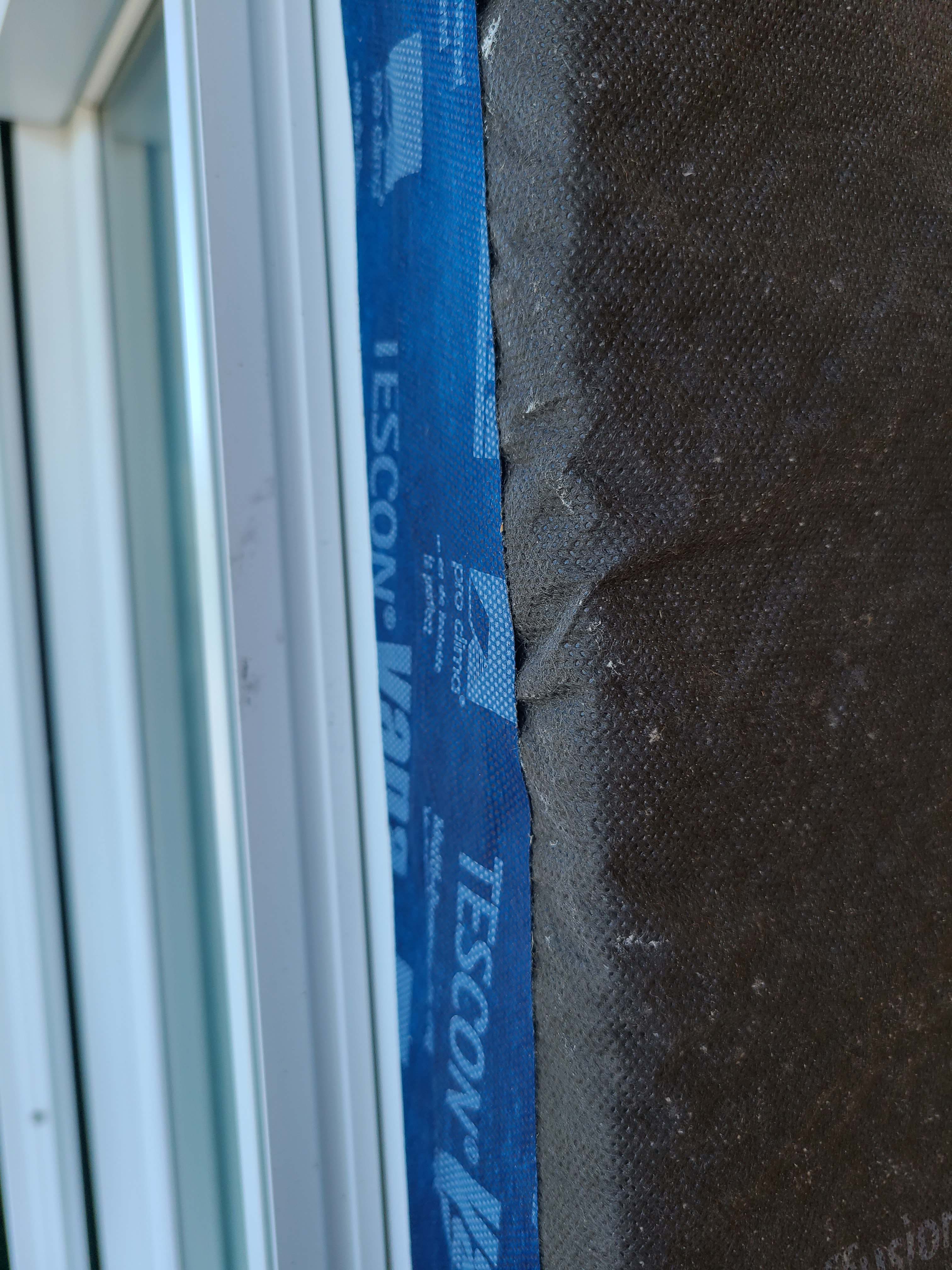
Windows are installed as “outies” in this wall assembly using a self-adhered membrane water and air control layer with continuous exterior insulation
Image
Image

Wrong - House wrap was poorly installed, seams were not taped, and flashing tape was not installed around windows.
Image
Wrong - House wrap and flashing tape are poorly installed allowing water to get into the gaps behind flashing tape.
Image

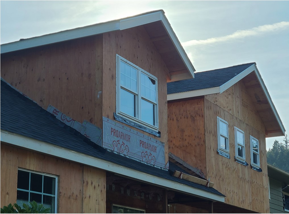
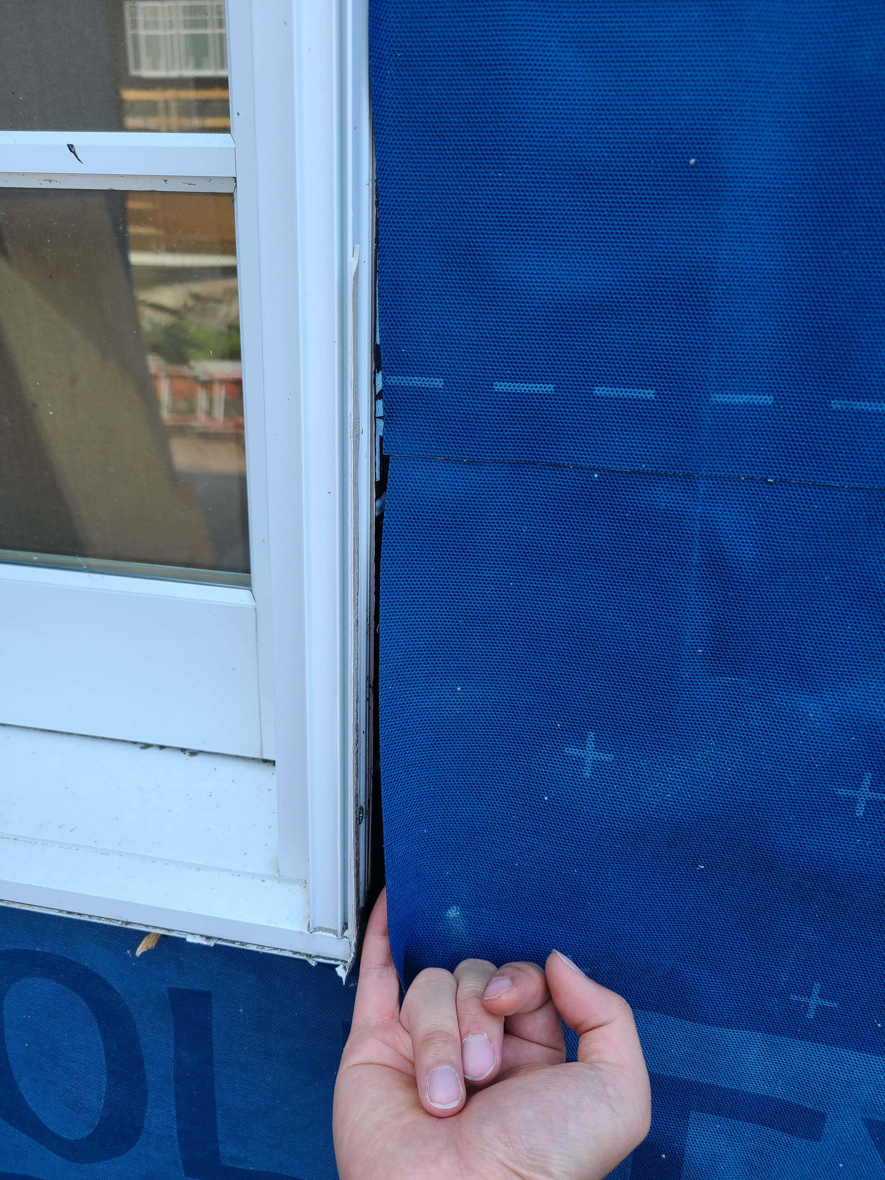
Wrong - House wrap tape is not fully adhered at seam and flashing tape is missing from window head, jamb, and corner above window.
Image
Image
Image
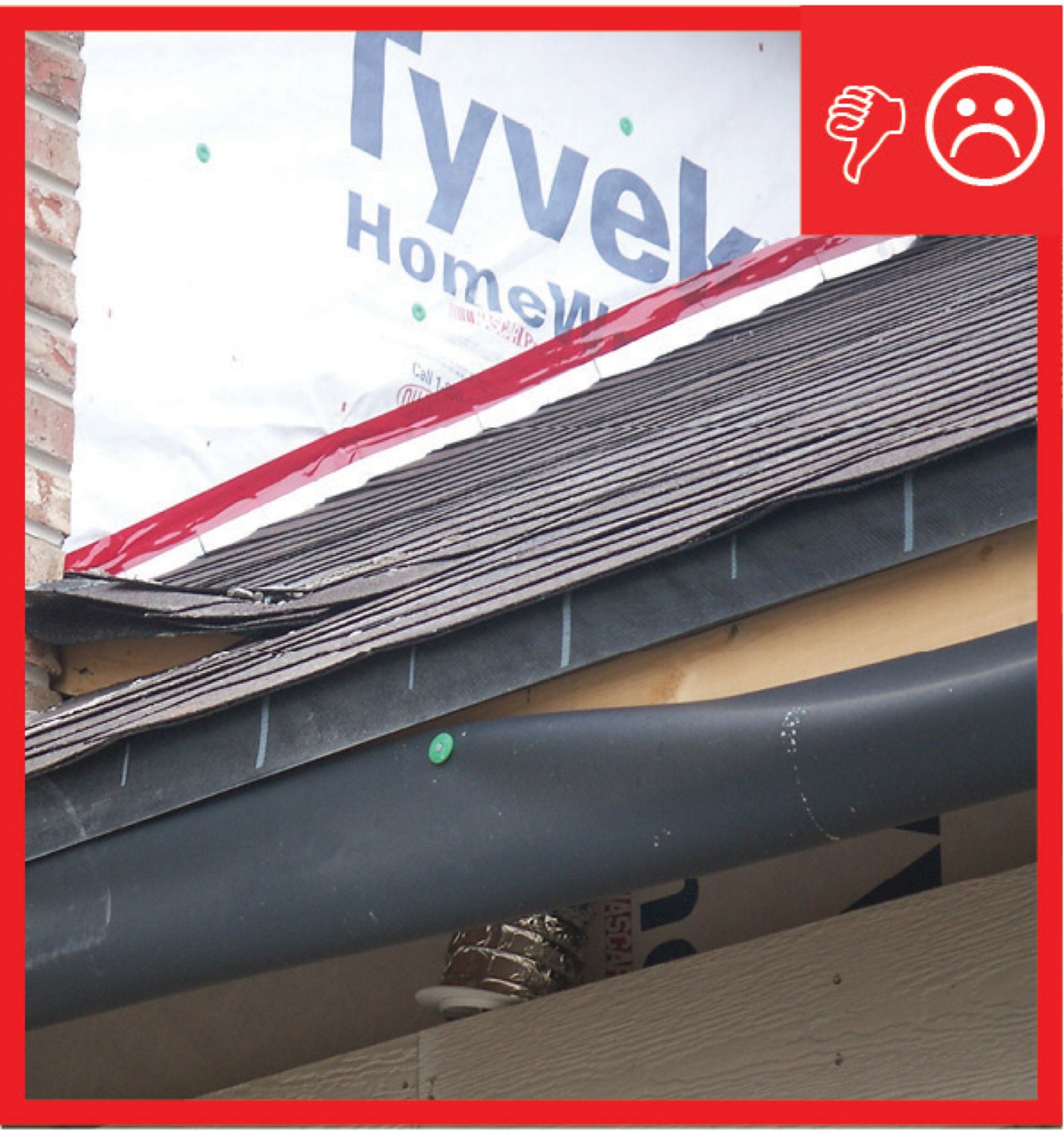
Wrong - Step flashing is missing where the gable meets roof and the valley flashing is incorrectly on top of rather than under shingles.
Image
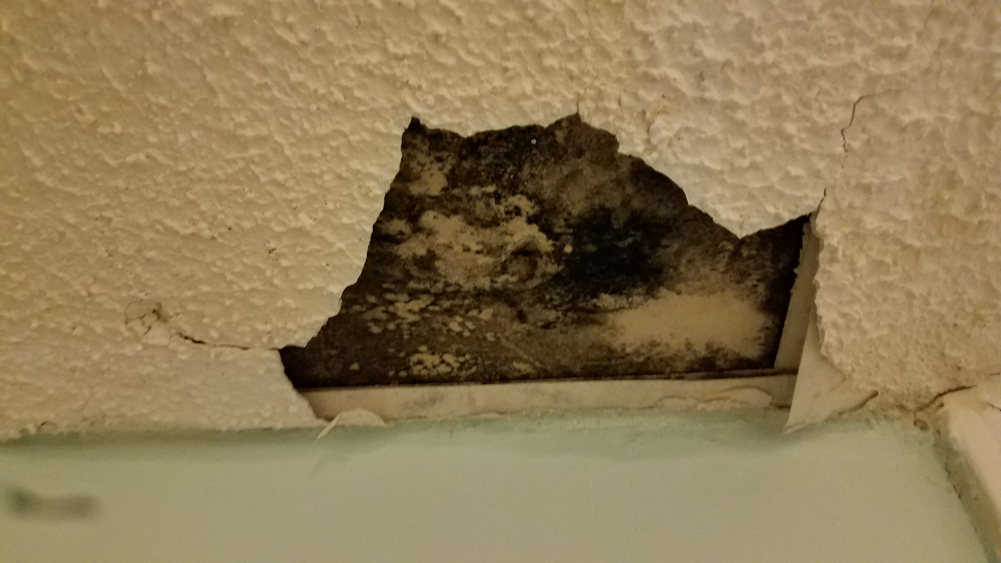
Wrong - Stucco has rotted and cracked above a window because of water damage due to lack of proper flashing and drainage.
Image
Image
Image

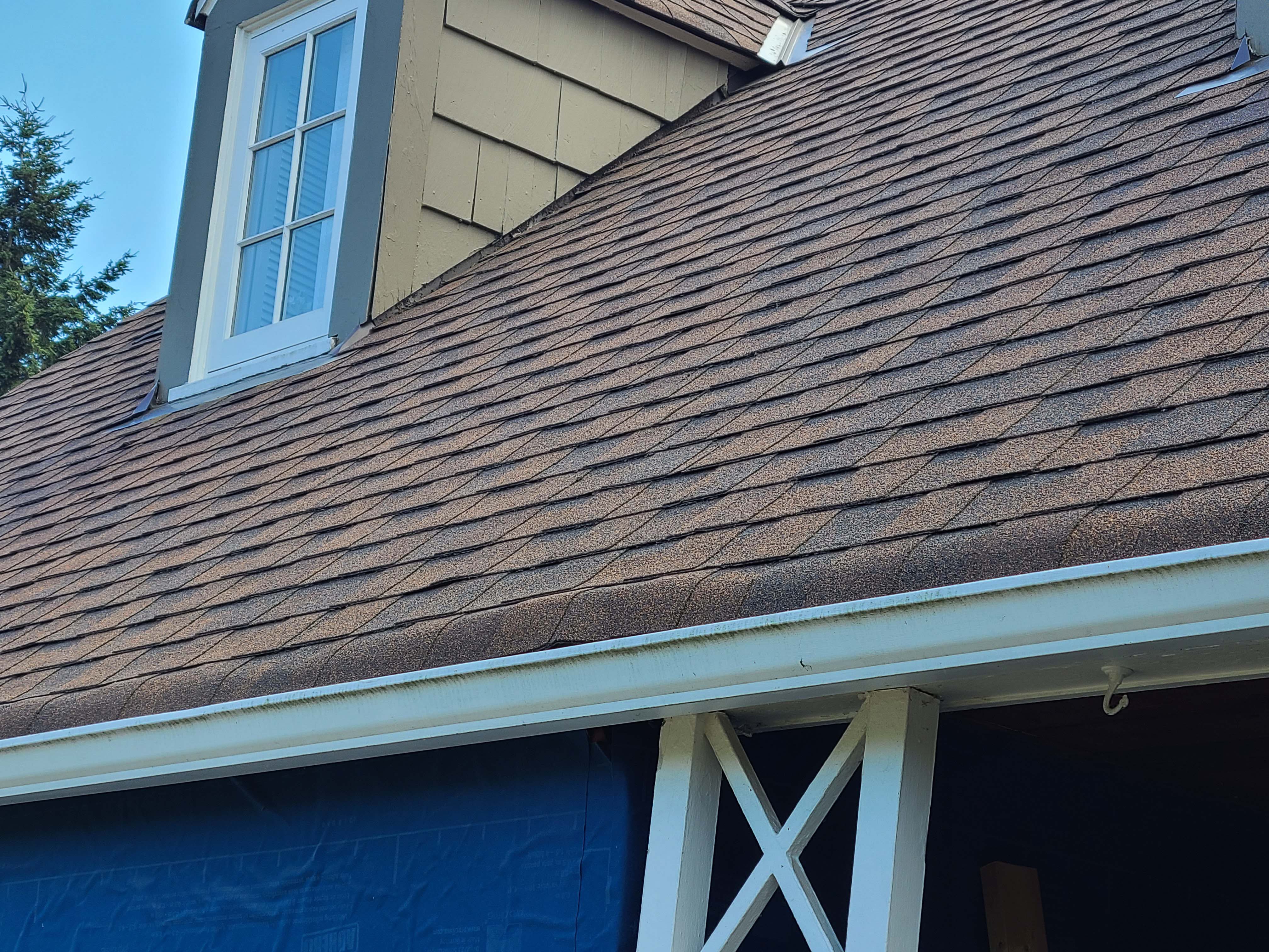
Wrong - The gutter is missing kick-out flashing causing wall and window damage beneath it.
Image

Wrong - The siding on the chimney is rotten because there is no metal step flashing at the base of the chimney.
Image

Image

Wrong - There is no step flashing along the base of the gable and the right window is missing sill trim.
Image
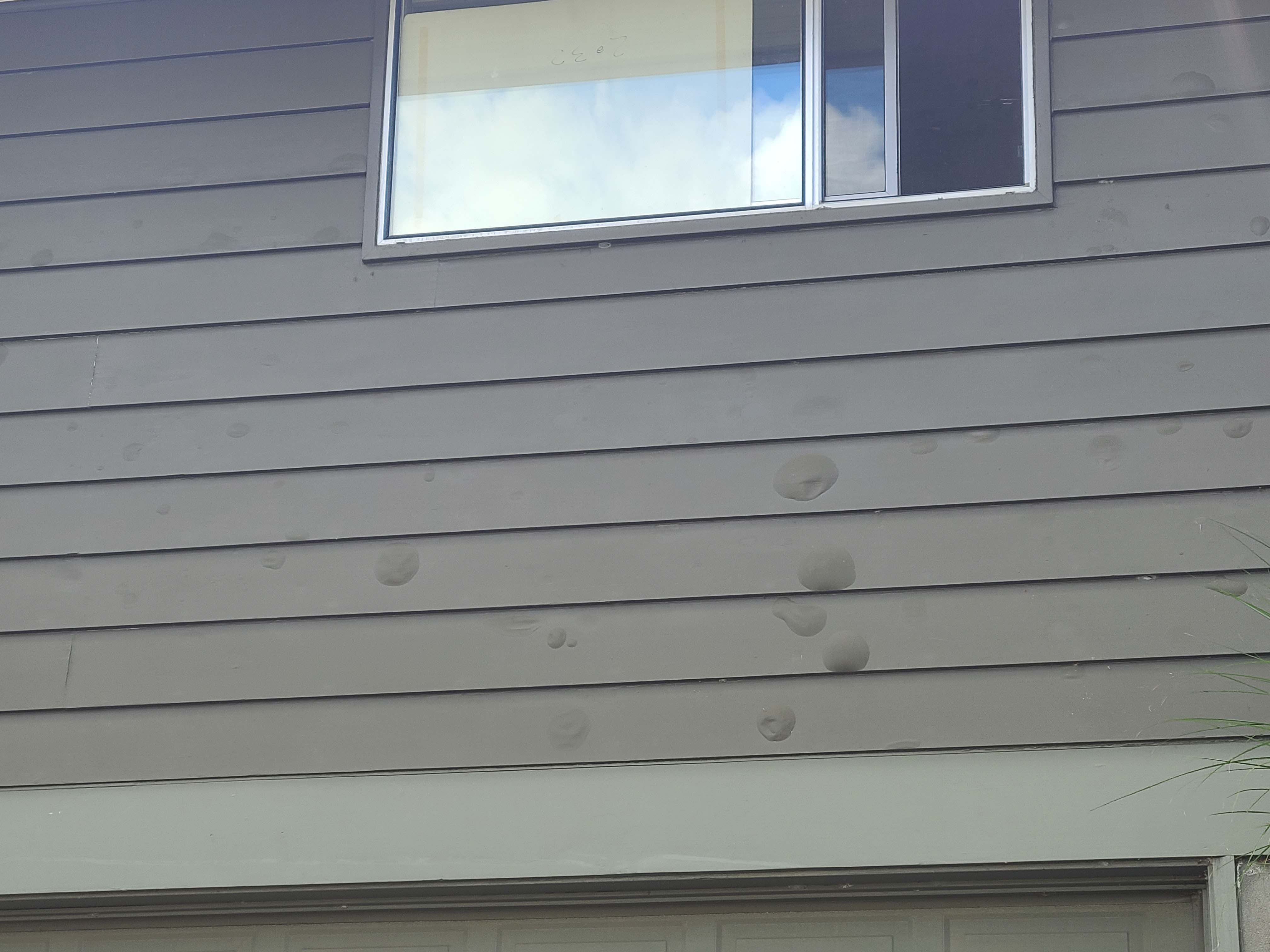
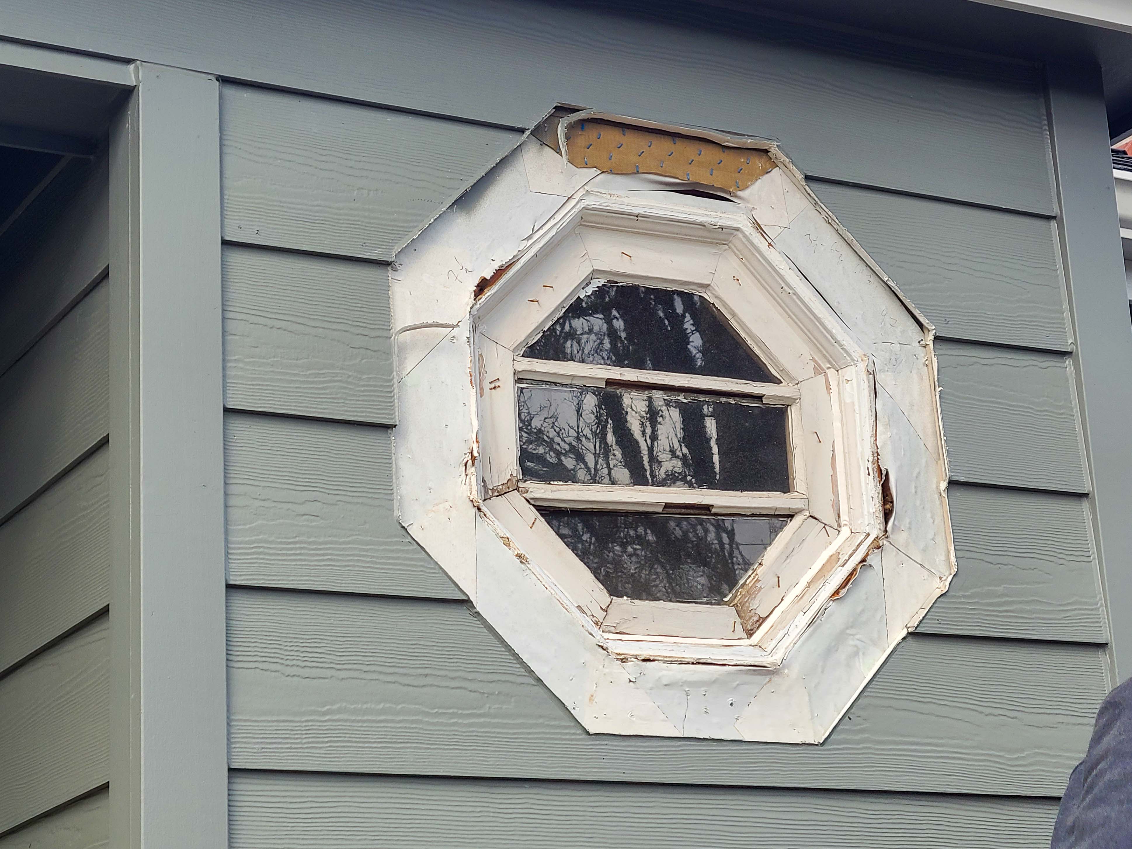
Wrong - Water has gotten behind the paint, possibly due to lack of window flashing, leading to blistering.
Image
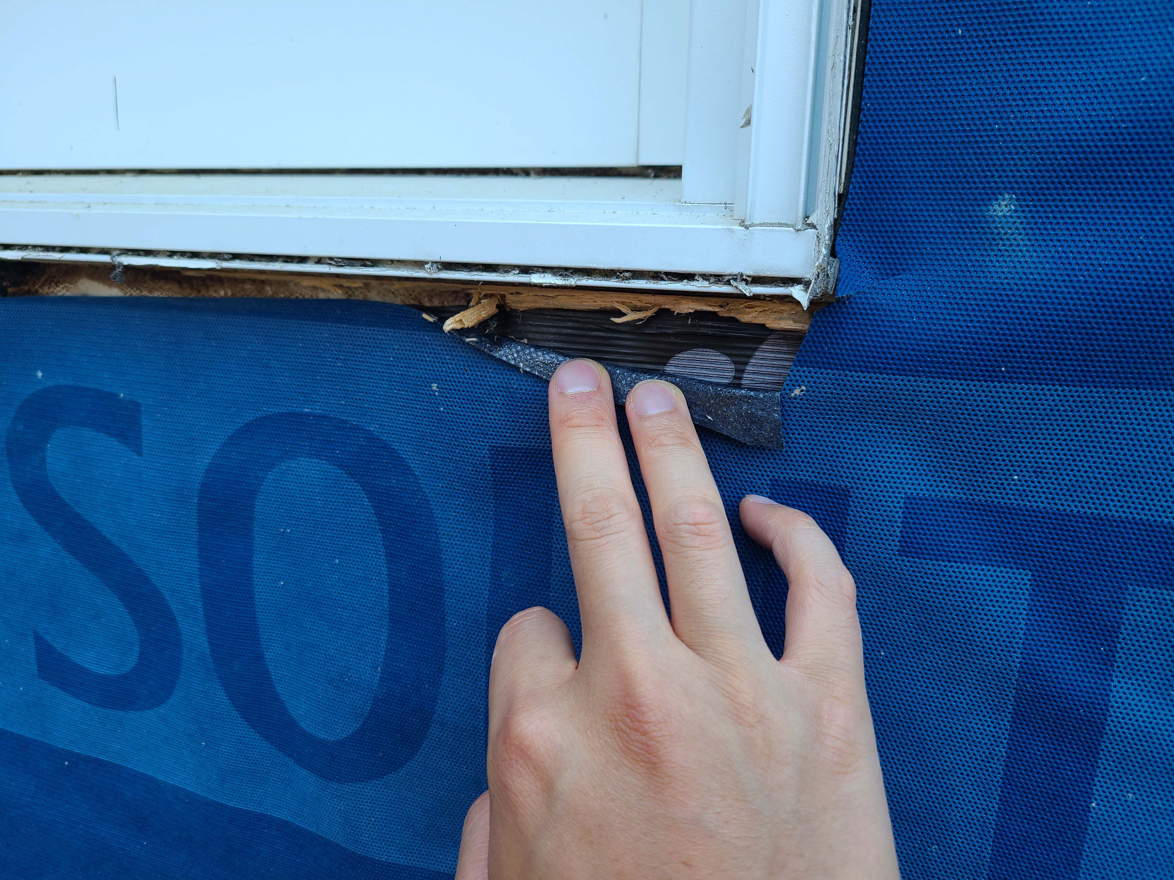
Wrong - Window is missing pan flashing under sill and tape flashing at jamb end sill.
Image
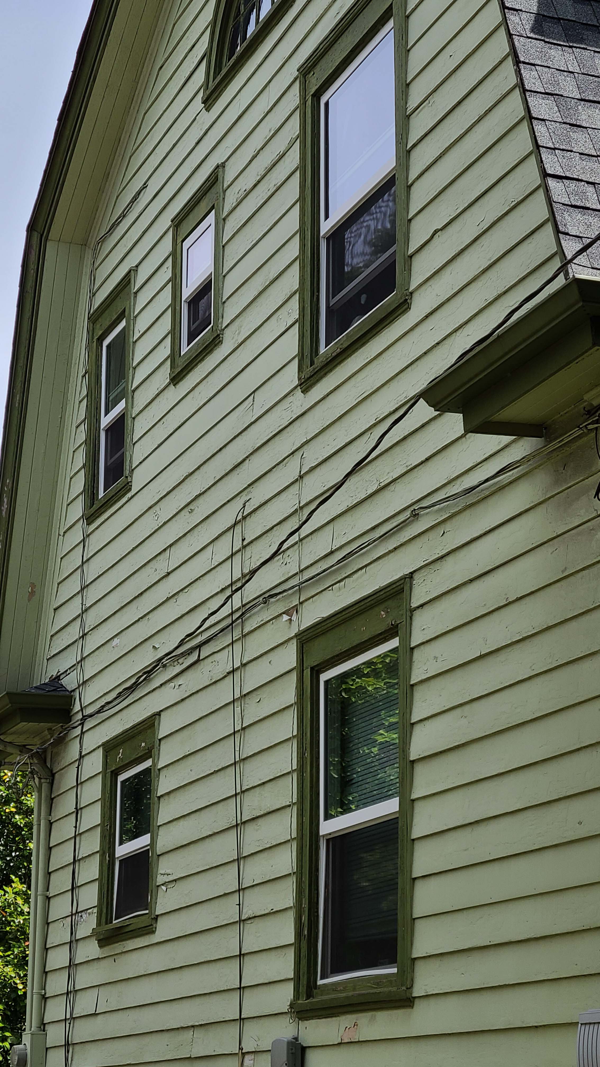
Wrong - Wiring holes are not sealed and possible missing flashing around windows is allowing water into walls and causing paint to peel.
Image
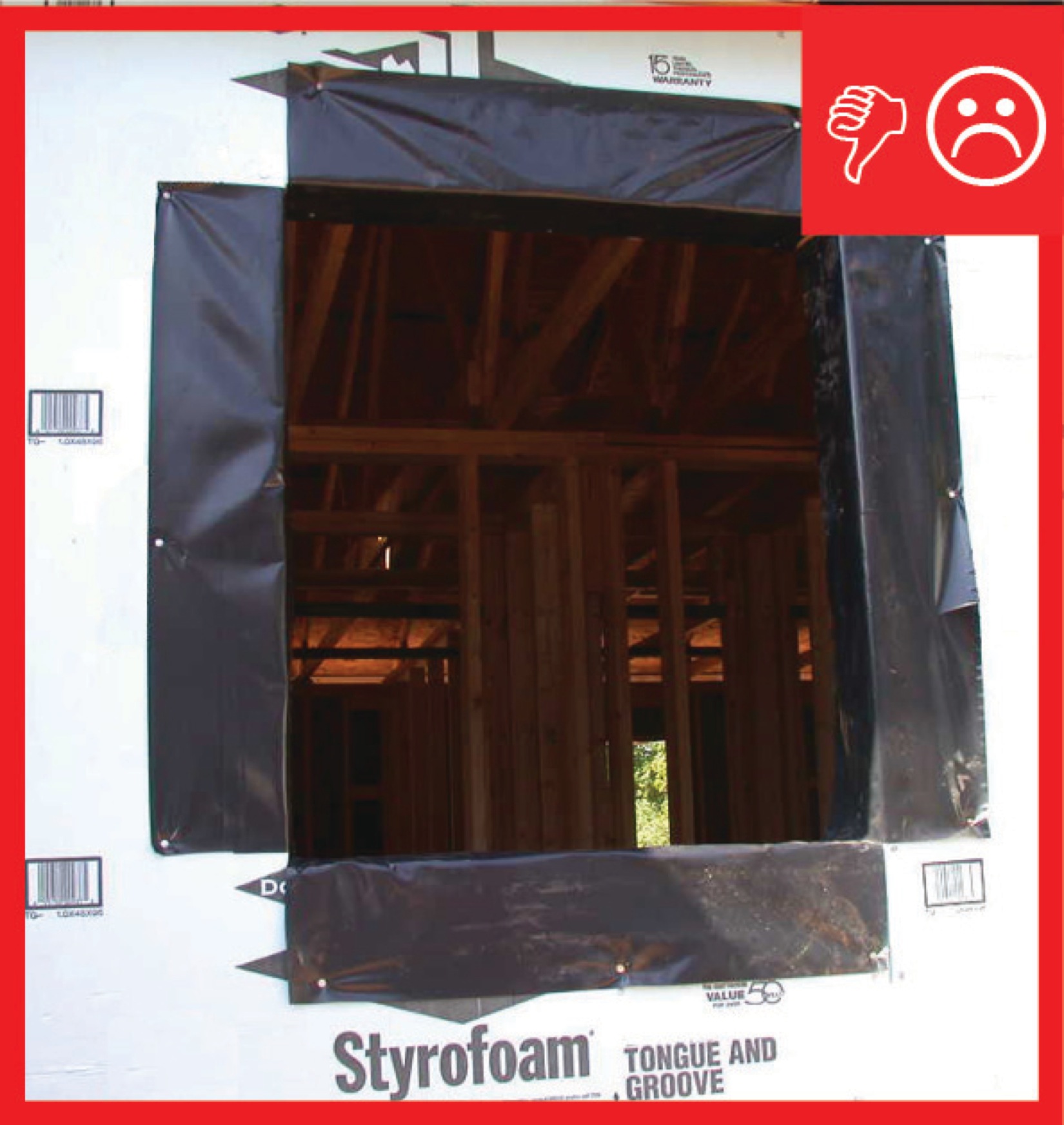
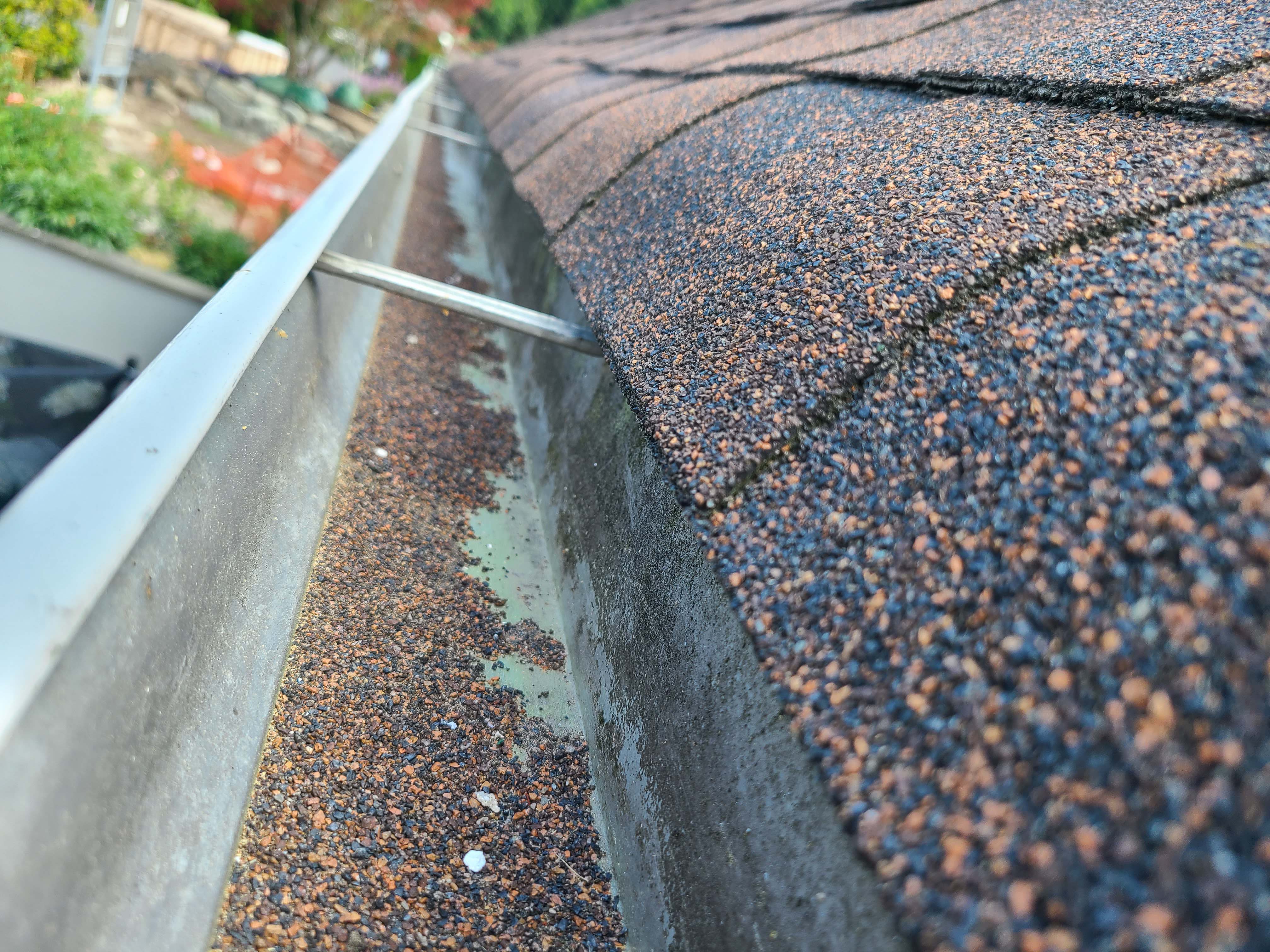
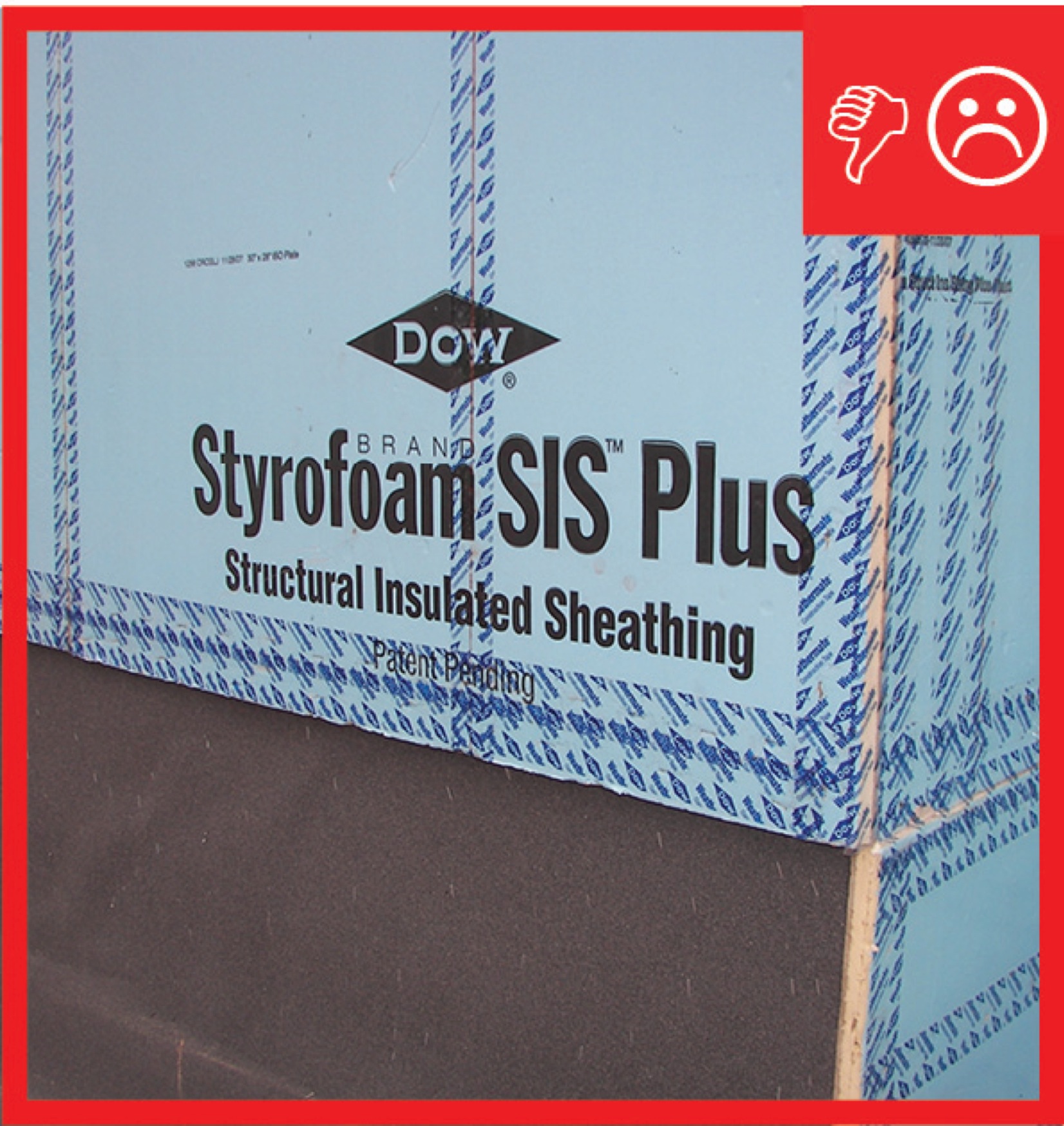
Wrong – The corners are not properly flashed, leaving a vulnerable area in the drainage system
Image
Image

Wrong – the water-resistant barrier is layered underneath the step flashing, which could allow water to get behind the step flashing and into the wall.
Image

Image
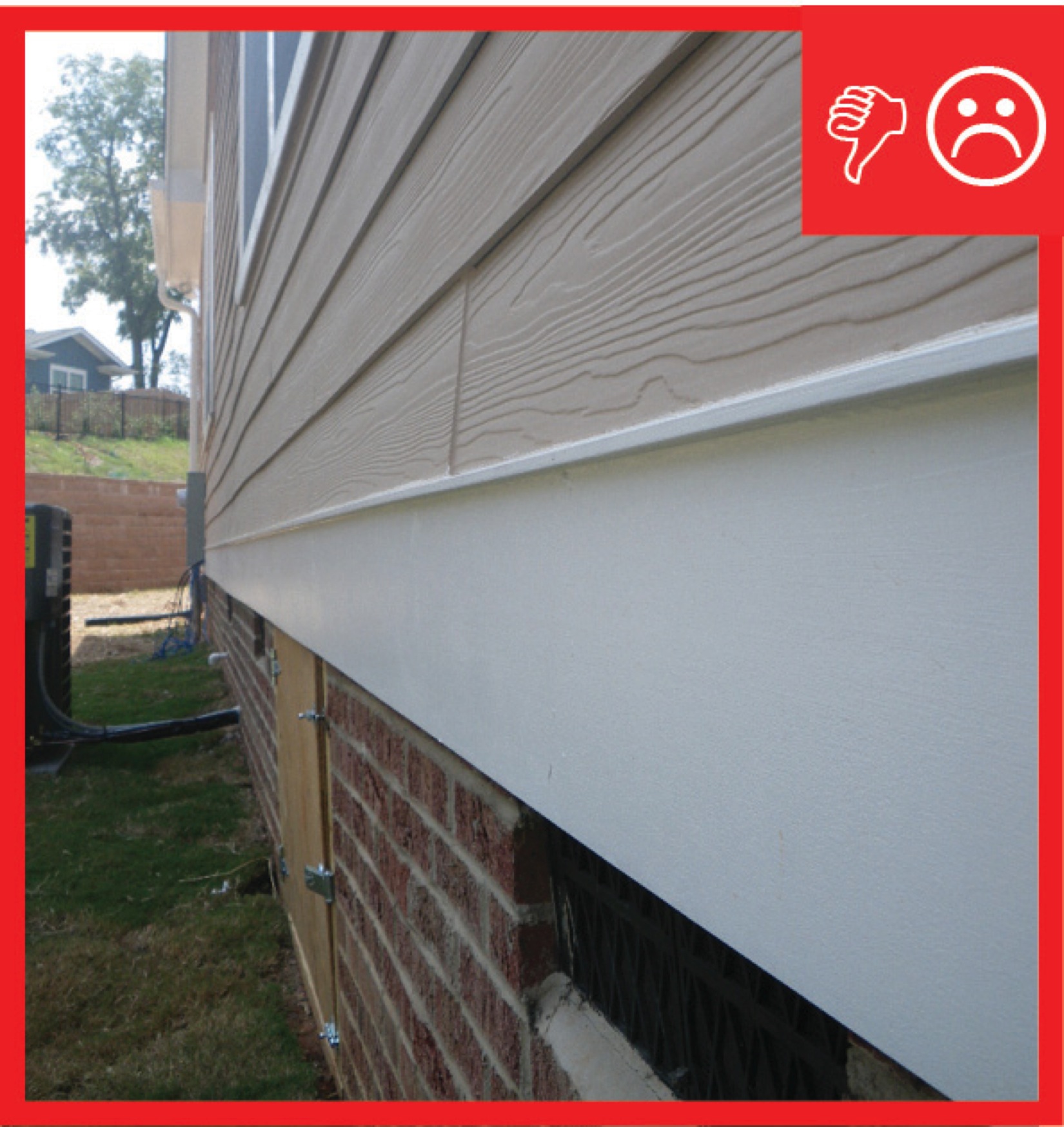
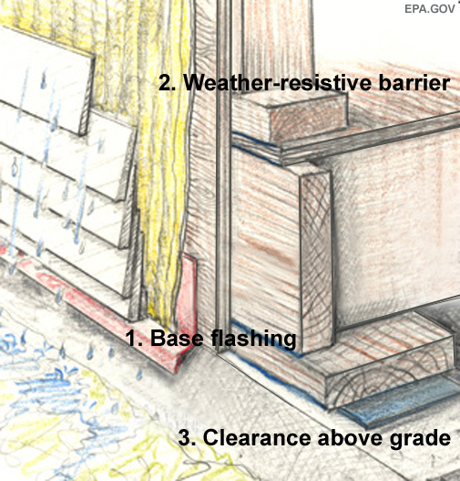
Wrong – There is no flashing installed at the bottom of the exterior walls to create a drainage system
Image
Wrong – There is no flashing installed at the bottom of the exterior walls to create a drainage system
Image