Showing results 1 - 19 of 19
Image
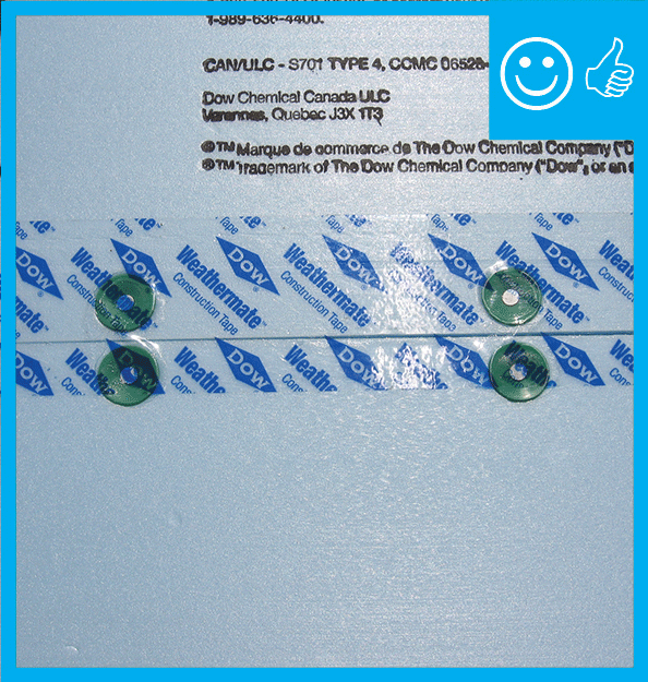
Right – Two-thirds of acrylic tape is offset above the joint and over and above the fasteners
Image
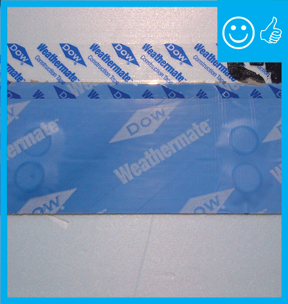
Right – two-thirds of the blue butyl flashing tape is above the sheathing seam; the top edge of the butyl flashing tape is covered with clear sheathing tape that is also offset so two-thirds is above the top edge of the butyl flashing.
Image

The windows in this building are connected to the fully adhered water and air control layer using fluid-applied flashing
Image
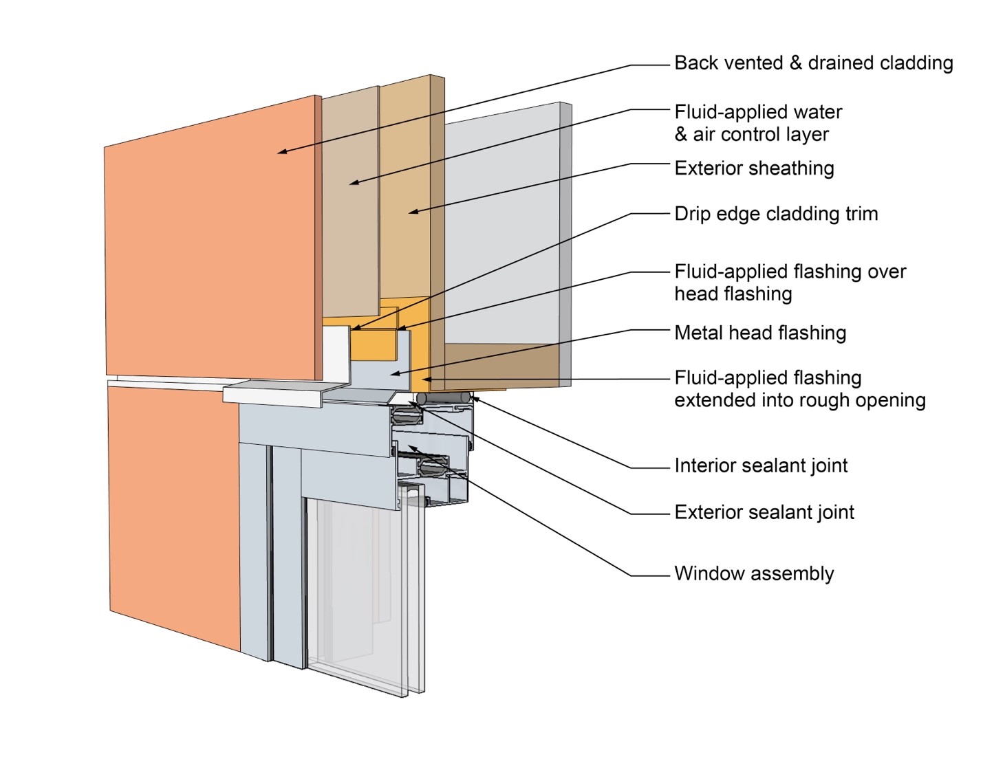
This drawing shows key head details for a window installation using a fluid-applied flashing on a wall with a fluid-applied water and air control layer
Image
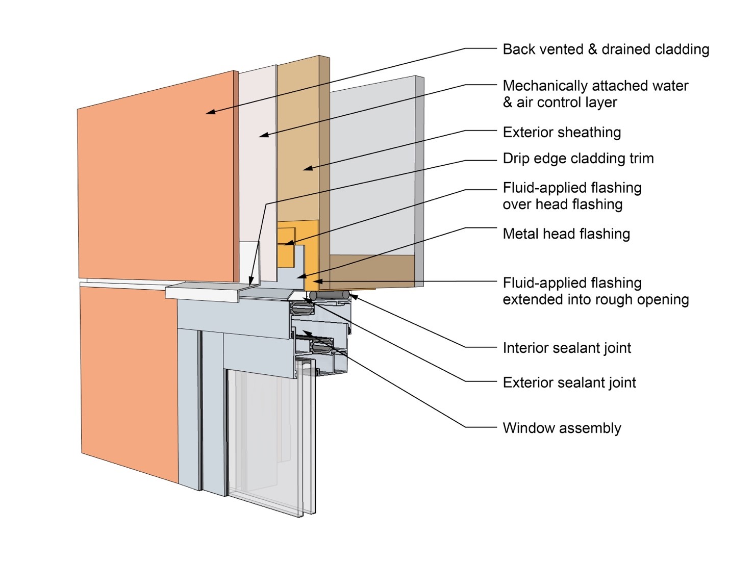
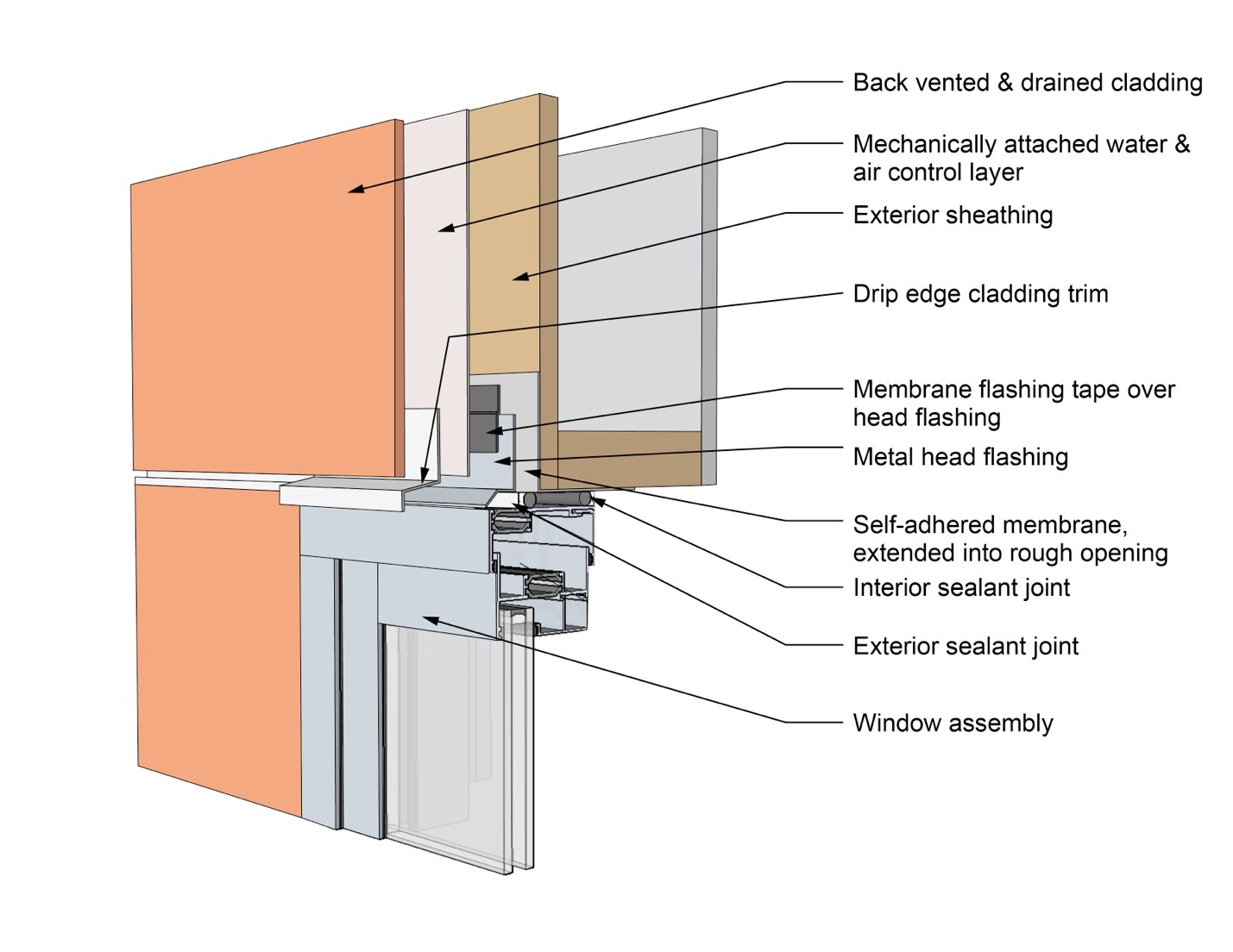
This drawing shows key head details for a window installation using a fluid-applied flashing on a wall with a mechanically attached water and air control layer
Image
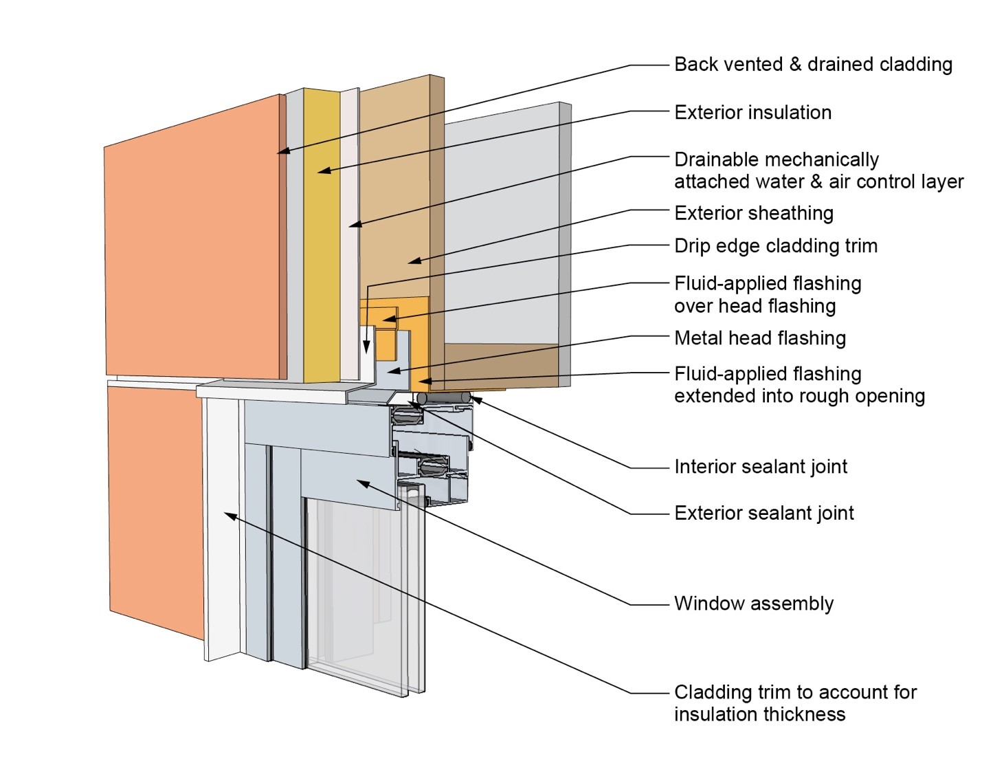
This drawing shows key head details for a window installation using a fluid-applied flashing on a wall with a mechanically attached water and air control layer and continuous insulation
Image
This drawing shows key head details for a window installation using a self-adhered membrane tape flashing on a wall with a mechanically attached water and air control layer
Image
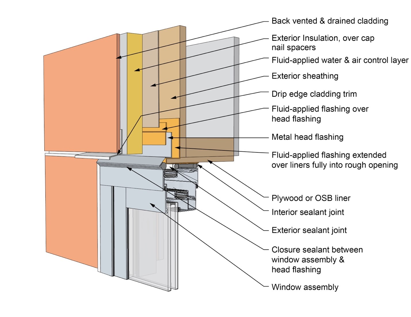
This drawing shows key head details for an “outie” window installation using a fluid-applied flashing on a wall with a fluid-applied water and air control layer and continuous insulation
Image
This drawing shows key jamb details for a window installation using a fluid-applied flashing on a wall with a fluid-applied water and air control layer
Image
This drawing shows key jamb details for a window installation using a fluid-applied flashing on a wall with a mechanically attached water and air control layer
Image
This drawing shows key jamb details for a window installation using a fluid-applied flashing on a wall with a mechanically attached water and air control layer and continuous insulation
Image
This drawing shows key jamb details for a window installation using a self-adhered membrane tape flashing on a wall with a mechanically attached water and air control layer
Image
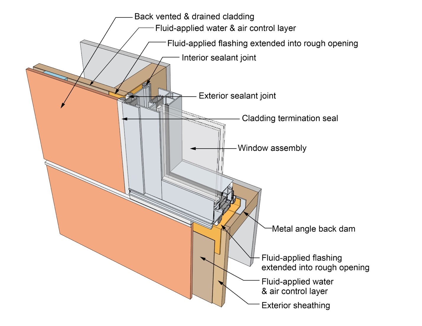
This drawing shows key jamb details for an “outie” window installation using a fluid-applied flashing on a wall with a fluid-applied water and air control layer and continuous insulation
Image
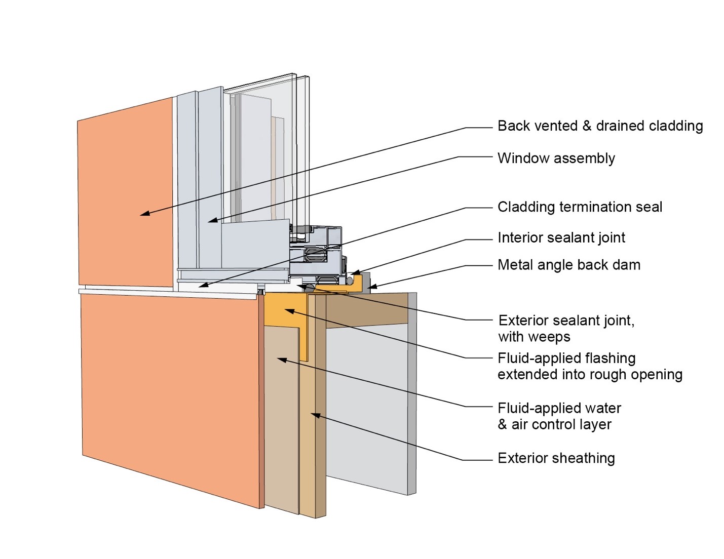
This drawing shows key sill details for a window installation using a fluid-applied flashing on a wall with a fluid-applied water and air control layer
Image
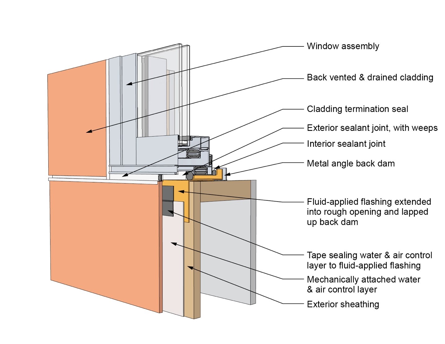
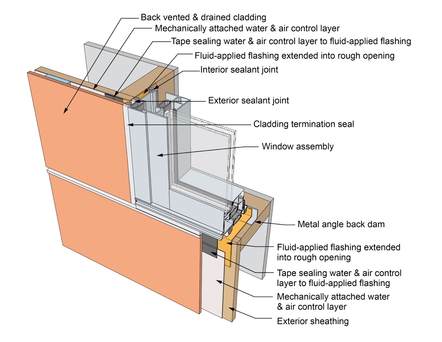
This drawing shows key sill details for a window installation using a fluid-applied flashing on a wall with a mechanically attached water and air control layer
Image
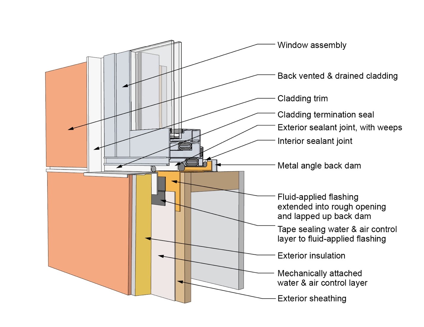
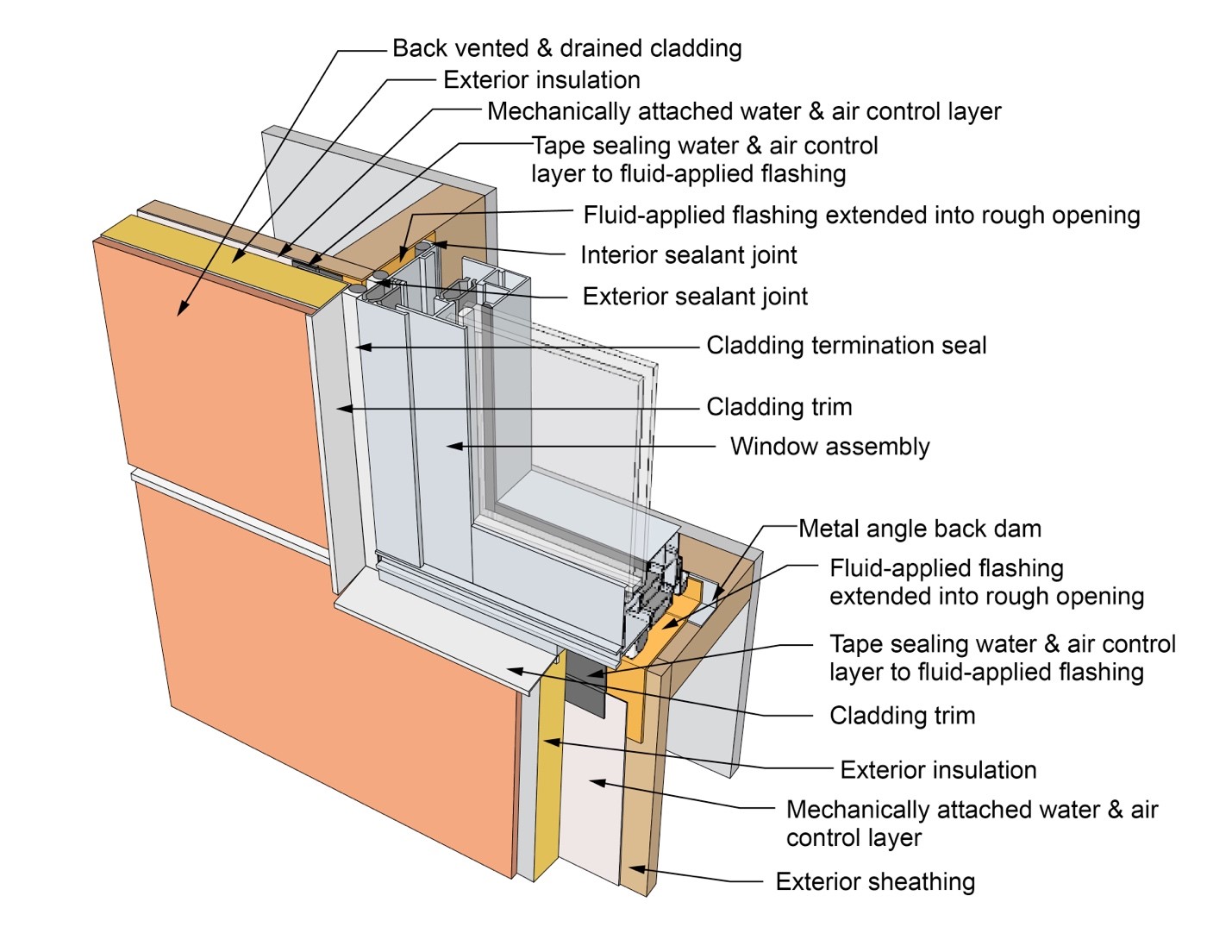
This drawing shows key sill details for a window installation using a fluid-applied flashing on a wall with a mechanically attached water and air control layer and continuous insulation
Image
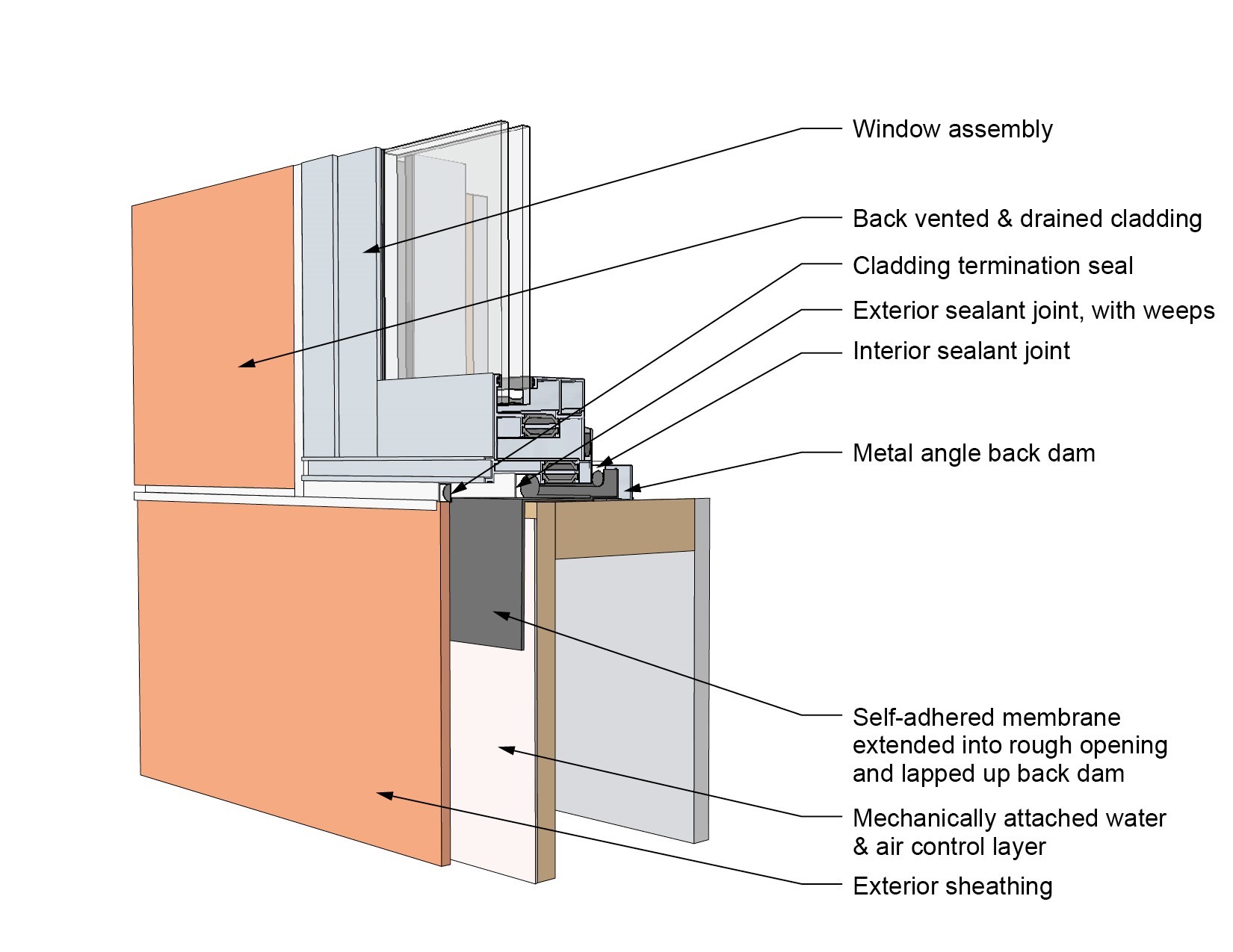
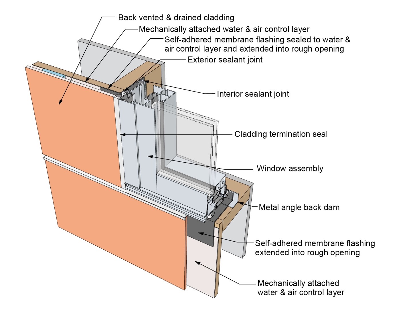
This drawing shows key sill details for a window installation using a self-adhered membrane tape flashing on a wall with a mechanically attached water and air control layer
Image
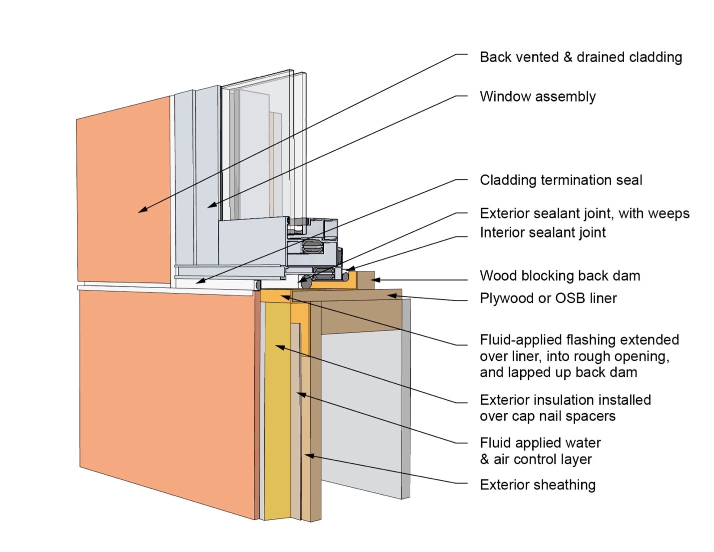
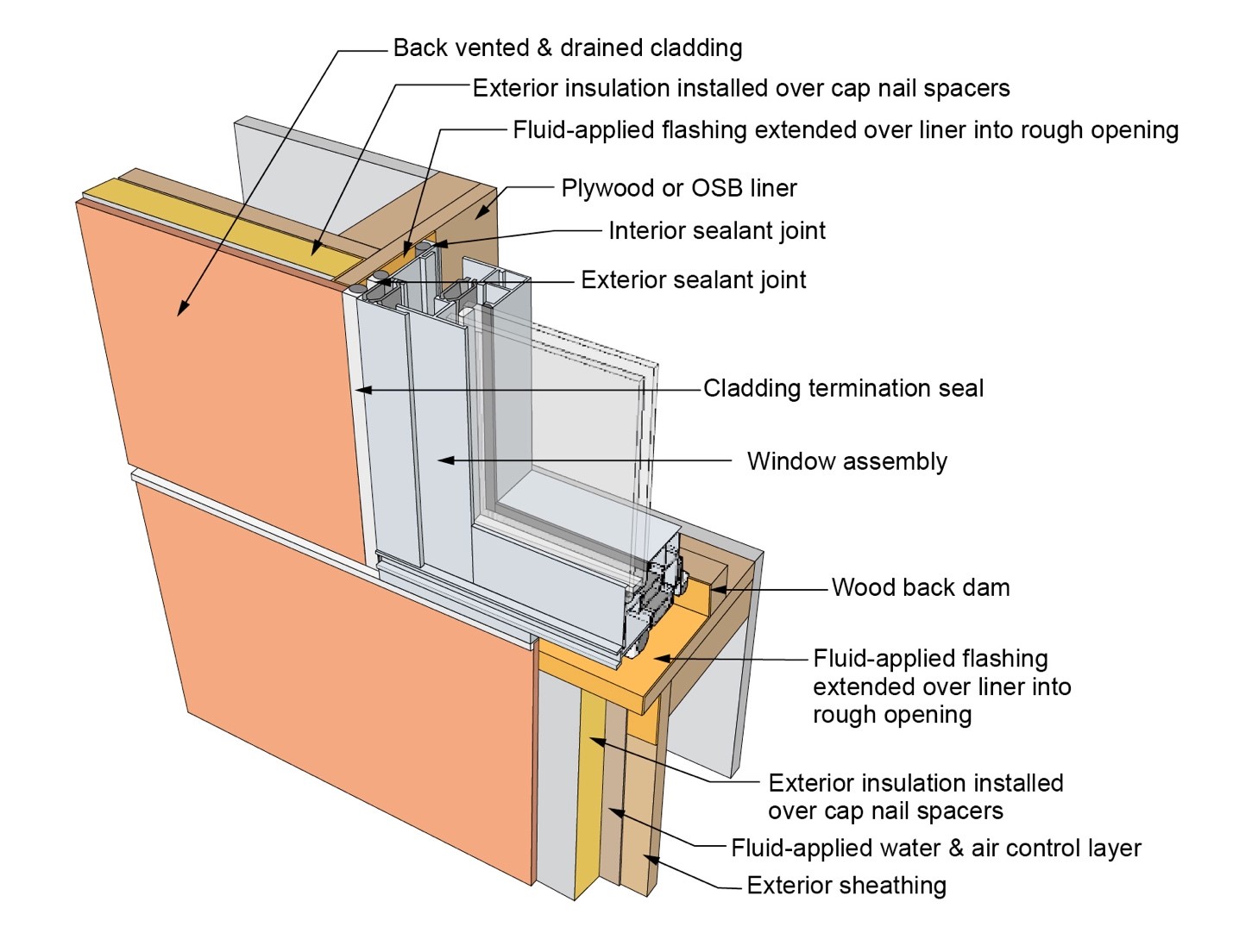
This drawing shows key sill details for an “outie” window installation using a fluid-applied flashing on a wall with a fluid-applied water and air control layer and continuous insulation
Image
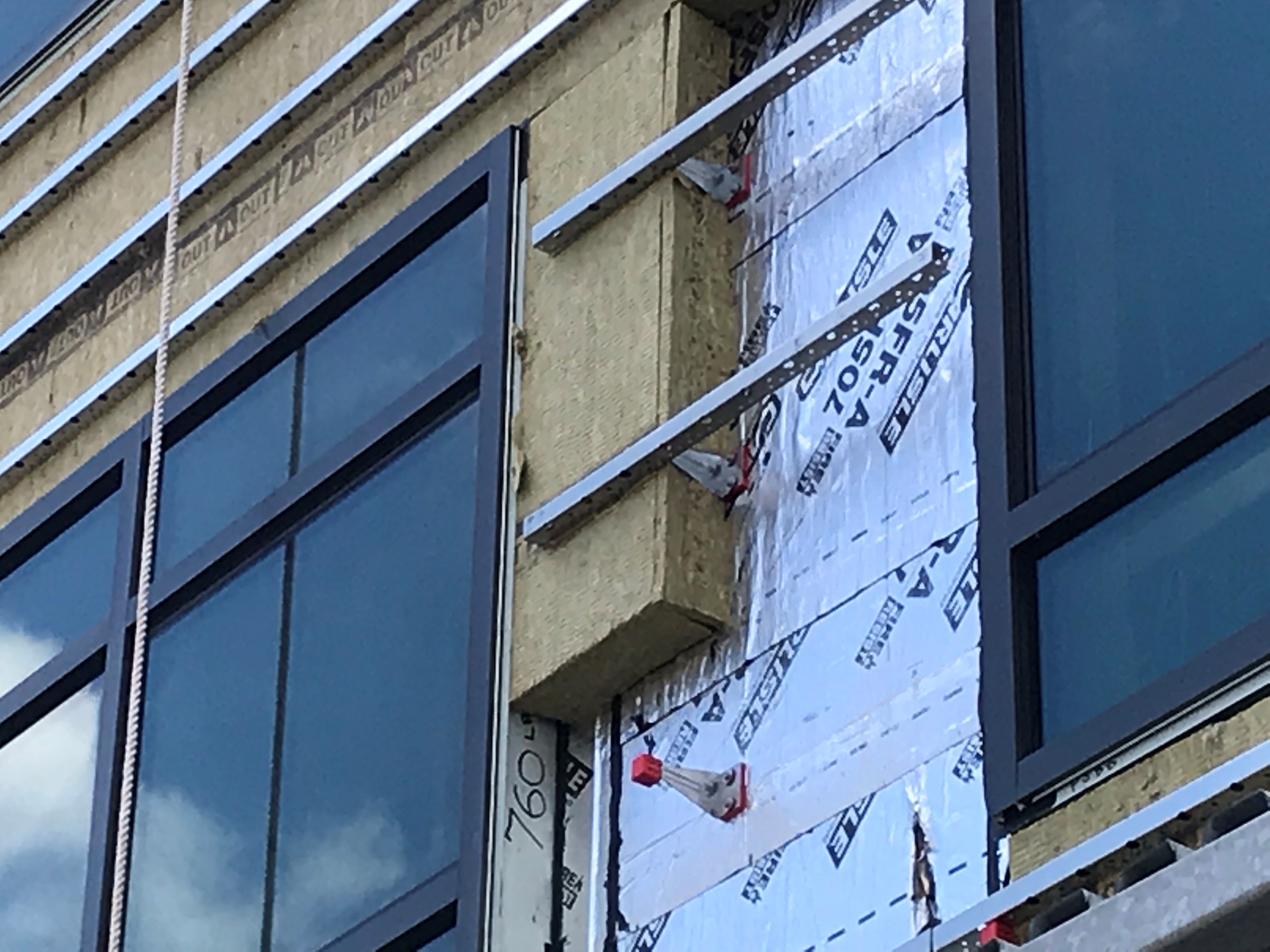
Windows are installed as “outies” in this wall assembly using a self-adhered membrane water and air control layer with continuous exterior insulation