

Drawings
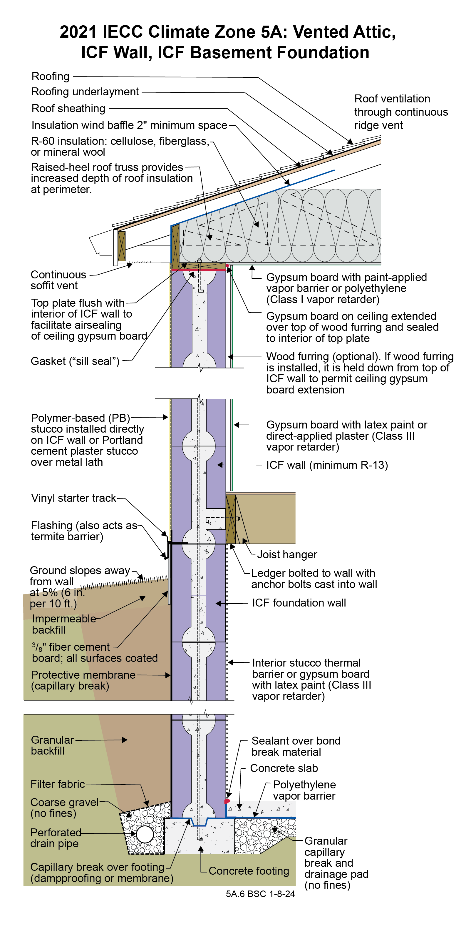
2021 IECC Climate Zone 5A: Vented Attic, ICF Wall, ICF Basement Foundation
Notes
Drawing 5A.6: IECC CZ 5: Vented Attic, ICF Wall, ICF Basement Foundation
- The function of the raised-heel roof truss is to control the temperature of the interior corner where the exterior wall meets the ceiling to control dust marking and mold. The minimum thermal resistance over the top of the wall assembly should match or exceed the thermal resistance of the wall assembly. Increasing the height of the raised heel can allow lower attic insulation levels by code. Per IECC 2021 Section R402.2.1, Ceilings with Attics, the ceiling insulation of this assembly can be R-49 rather than R-60 if the raised-heel roof truss is high enough to facilitate R-49 over the entire wall.
- A low-permeance roofing underlayment (less than 1 perm) is recommended for this roof type in this climate to reduce water diffusion through the underlayment to the sheathing.
- The ceiling gypsum board is installed prior to the wall gypsum board in order to accommodate a “filet” bead of sealant that seals the ceiling gypsum board to the top plates creating a continuous air control layer (“air barrier”) across the entire ceiling including interior partition walls.
- ICF assemblies need an interior thermal barrier for fire protection – either gypsum board or stucco.
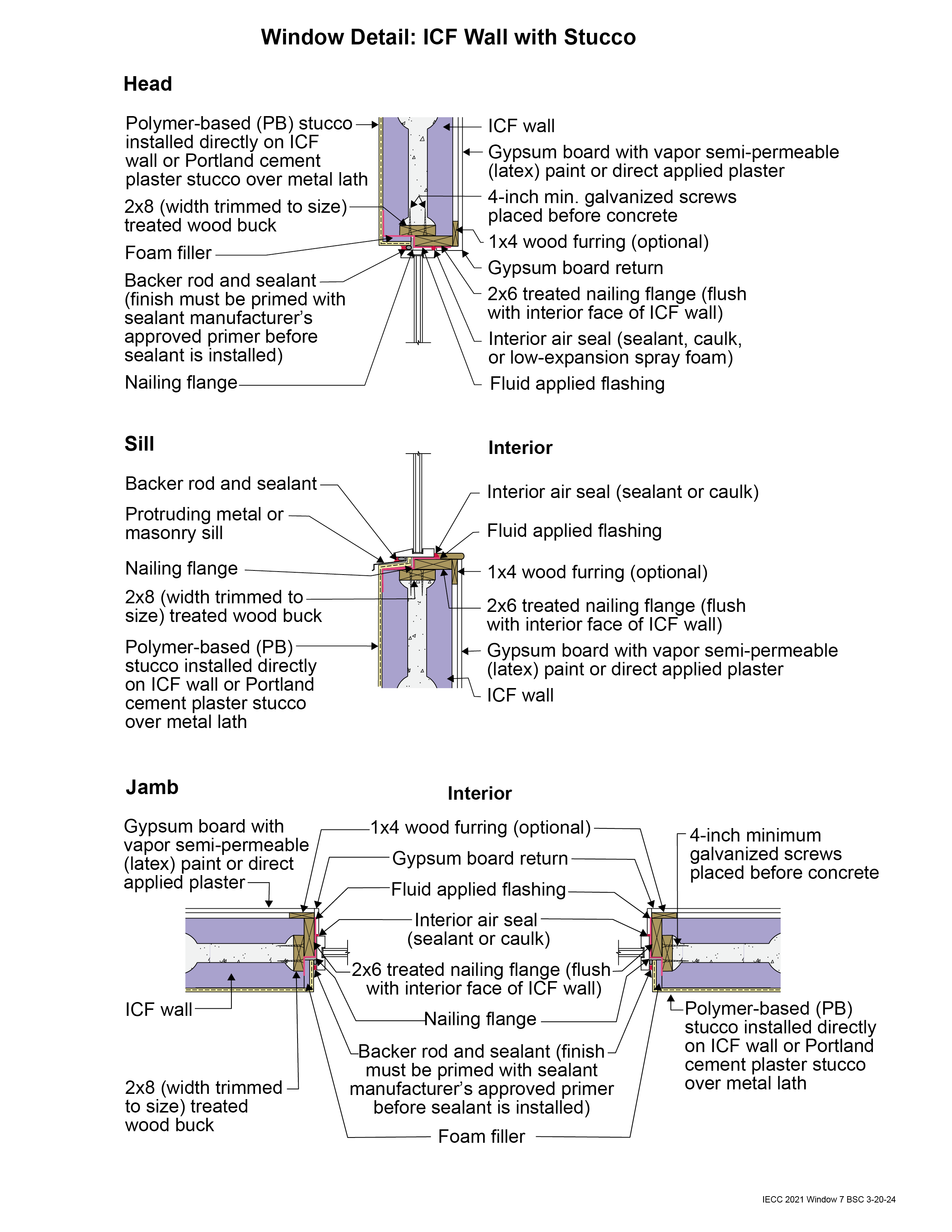
2021 IECC Window Detail: ICF Wall with Stucco
Notes
Window Detail 7 - ICF Wall with Stucco
- Note: Always follow the window manufacturer’s installation guidance. Not following manufacturer guidance may void the warranty.
- This is a “mass/storage wall” where rainwater is controlled by the stucco that is directly adhered to the insulating concrete form (ICF). This is not a “drained wall.” Any water that passes through the stucco is stored, absorbed, and redistributed within the wall assembly and then dries to the exterior or interior or both. The window openings are drained to the exterior of the wall.
- The window rough opening is flashed to the face of the ICF with a fluid-applied membrane flashing. The window flanges are flashed to this water control layer.

