


Drawings
2021 IECC Climate Zone 2B: Vented Attic, Block Wall, Slab on Grade
Notes
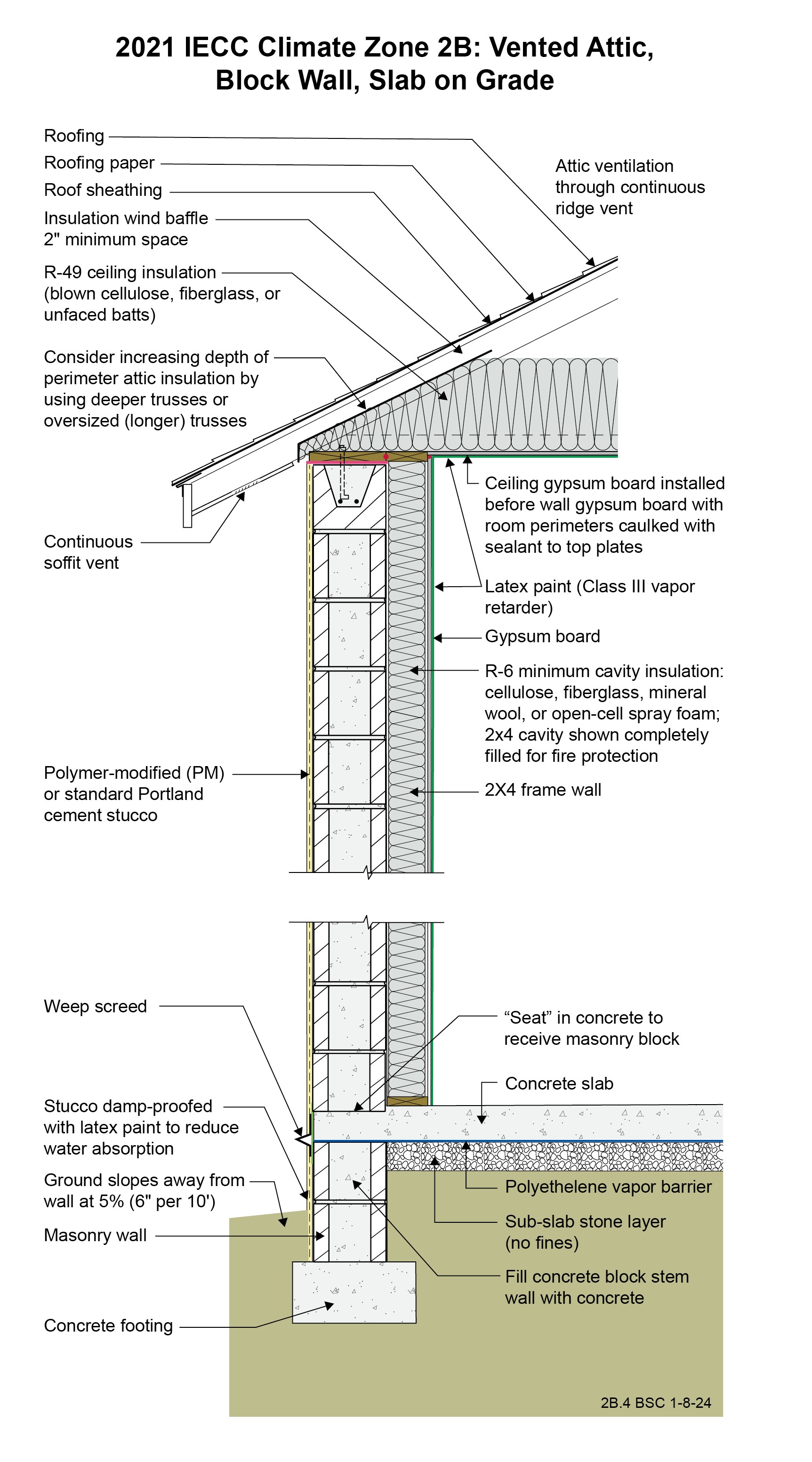
Drawing 2B.4: IECC CZ 2B: Vented Attic, Block Wall, Slab on Grade
- If a raised-heel roof truss is used to allow R-38 attic insulation over the full width of the exterior wall, then R-38 can be used throughout the attic rather than R-49. See Section R402.2.1 of the 2021 IECC.
- The block wall is framed on the interior with wood framing to facilitate installation of electrical services. The framing cavities are insulated with cellulose, fiberglass, or mineral wool. Although it is feasible to install the minimum-required R-6 insulation in the 2x4 wall cavity, fire code may require the entire cavity to be filled, likely resulting in a higher R-value.
- A class III vapor retarder (latex paint) is used on the interior surface of the walls and ceiling instead of a vapor barrier. This allows drying to the interior. Avoid vinyl wallpaper and oil-based paint or coatings in Climate Zone 2. These wall coverings are vapor impermeable and increase the risk of condensation within the wall.
- The polyethylene vapor barrier under the concrete slab extends over the top of the CMU stem wall to act as a capillary break.
- Portions of the CMU wall may need to be filled solid to meet structural requirements or to accommodate anchor bolts for a sill plate.
2021 IECC Window Detail: CMU Wall with Stucco
Notes
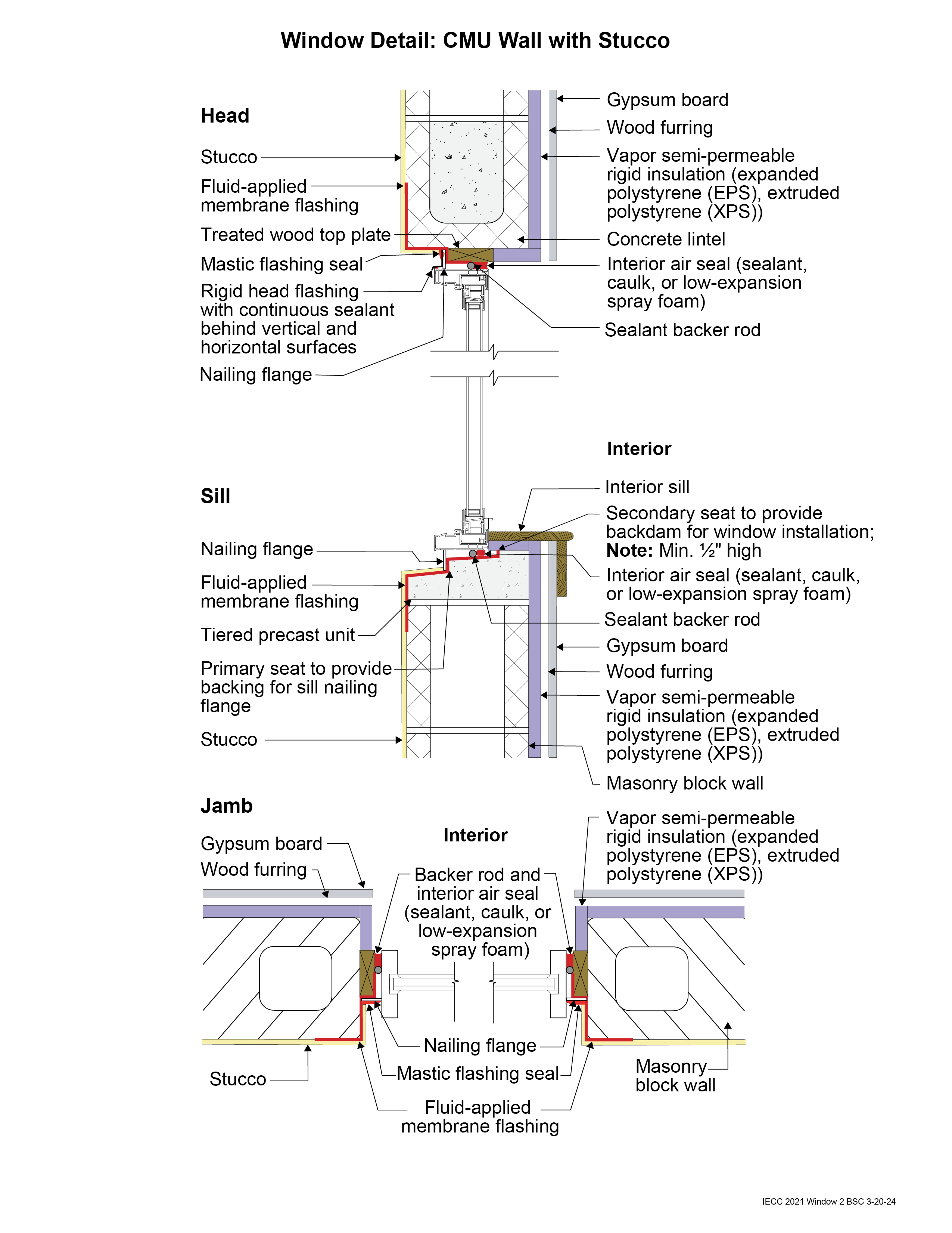
Window Detail 2 - CMU Wall with Stucco
- Note: Always follow the window manufacturer’s installation guidance. Not following manufacturer guidance may void the warranty.
- This is a “mass/storage wall” where rainwater is controlled by the stucco that is directly adhered to the CMU. This is not a “drained wall”. Any water that passes through the stucco is stored, absorbed, and redistributed within the wall assembly and then dries to the exterior or interior or both.
- The window openings are drained to the exterior of the wall.
- The window rough opening is flashed to the face of the CMU with a fluid-applied membrane flashing. The fluid-applied membrane flashing is applied to the rough opening inwards at least past the point where the interior air seal is located around all sides of the frame. This creates water-resistant surfaces inside the cavity between the window flanges and the interior air seal, in case any water gets behind the flanges. The window flanges (head and jambs only) are flashed to this fluid-applied membrane using a mastic flashing seal or self-adhered flashing membrane. Note the tiered precast unit at the window sill opening. This provides drainage to the exterior of the wall. The window is installed using shims just like with a wood-framed sill. The secondary seat, or backdam, of the precast sill should be located far enough to the interior to allow space between it and the window so that shims can be adjusted during installation, and to allow the interior air seal backer rod and sealant to be installed. A sill can be made of treated lumber as an alternative to the tiered precast sill. The sill should still be sloped for drainage.
- It is vital that the mastic flashing seal at the window head and jamb flanges is carefully detailed. There is no mastic flashing seal over the window flange at the sill. This is to allow any water that may get past the head or jamb flanges to drain back out.
- Backer rod for the interior air sealant should be installed after the window is installed, leveled, and shimmed. Use correctly sized backer rod.


