


Drawings
2021 IECC Climate Zone 2A: Unvented Attic with Spray Foam at Roof Deck, 2x6 Wall-CMU Wall, Elevated Slab
Notes
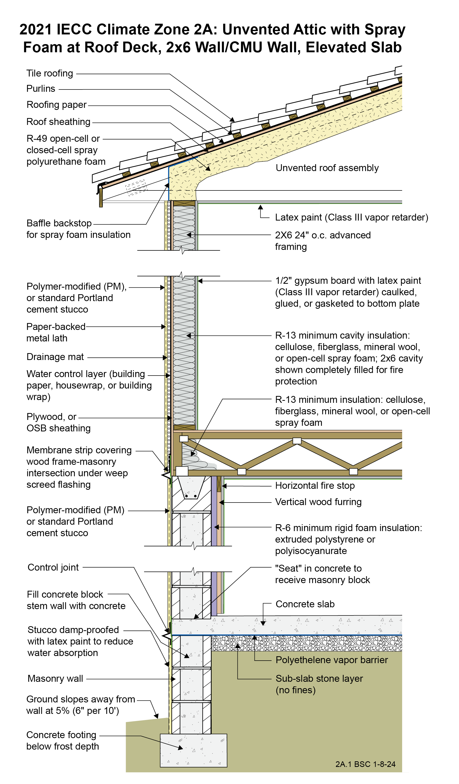
Drawing 2A.1: IECC CZ 2A: Unvented Attic with Spray Foam at Roof Deck, 2x6 Wall/CMU Wall, Elevated Slab
- The spray foam in the roof assembly can be either open-cell or closed-cell spray polyurethane foam. Closed-cell spray polyurethane foam significantly improves the wind uplift resistance of the roof assembly under hurricane conditions.
- If a raised-heel roof truss is used to allow R-38 attic insulation over the full width of the exterior wall, then R-38 can be used throughout the attic rather than R-49. See Section R402.2.1 of the 2021 IECC.
- A drainage mat is provided behind the stucco layer installed over the frame wall to control hydrostatic pressure. This assembly is drained to the exterior at a weep screed located at the bottom of the wood framing. It should not be drained into the CMU wall.
- The wood frame wall is framed with 2x6 24” o.c. advanced framing as it uses less board footage (volume of wood framing) than standard 2x4 16” o.c. framing and therefore is less expensive in material cost. It is also less expensive in labor (25% fewer framing members) and is faster to assemble. Although the code allows for 2x4 framing and lower R-value cavity insulation, the use of advanced framing and the associated cost savings more than offset the increase in the cost of cavity insulation (this of course depends on relative price fluctuations in labor and materials).
- Although the minimum R-value of the insulation in this wall is R-13 per IECC, fire code may require the entire cavity to be filled, likely resulting in a higher R-value for a 2x6 wall.
- Avoid vinyl wallpaper and oil-based paint or coatings in Climate Zone 2A. These wall coverings are vapor impermeable and increase the risk of condensation within the wall.
- The interior of the CMU wall is insulated with rigid insulation that also controls inward vapor drive out of the CMU mass wall. The thickness of the rigid insulation is typically selected to allow electrical boxes to be installed on the interior surface of the CMU mass wall without having to chisel the masonry blocks to seat the electrical boxes. Although only R-6 rigid foam insulation is needed on the interior of the CMU wall to meet energy efficiency code, thicker insulation may be needed to accommodate electrical outlets.
- The polyethylene vapor barrier under the concrete slab extends over the top of the CMU stem wall to act as a capillary break.
- Portions of the CMU wall may need to be filled solid to meet structural requirements or to accommodate anchor bolts for a sill plate.
2021 IECC Window Detail: CMU Wall with Stucco
Notes
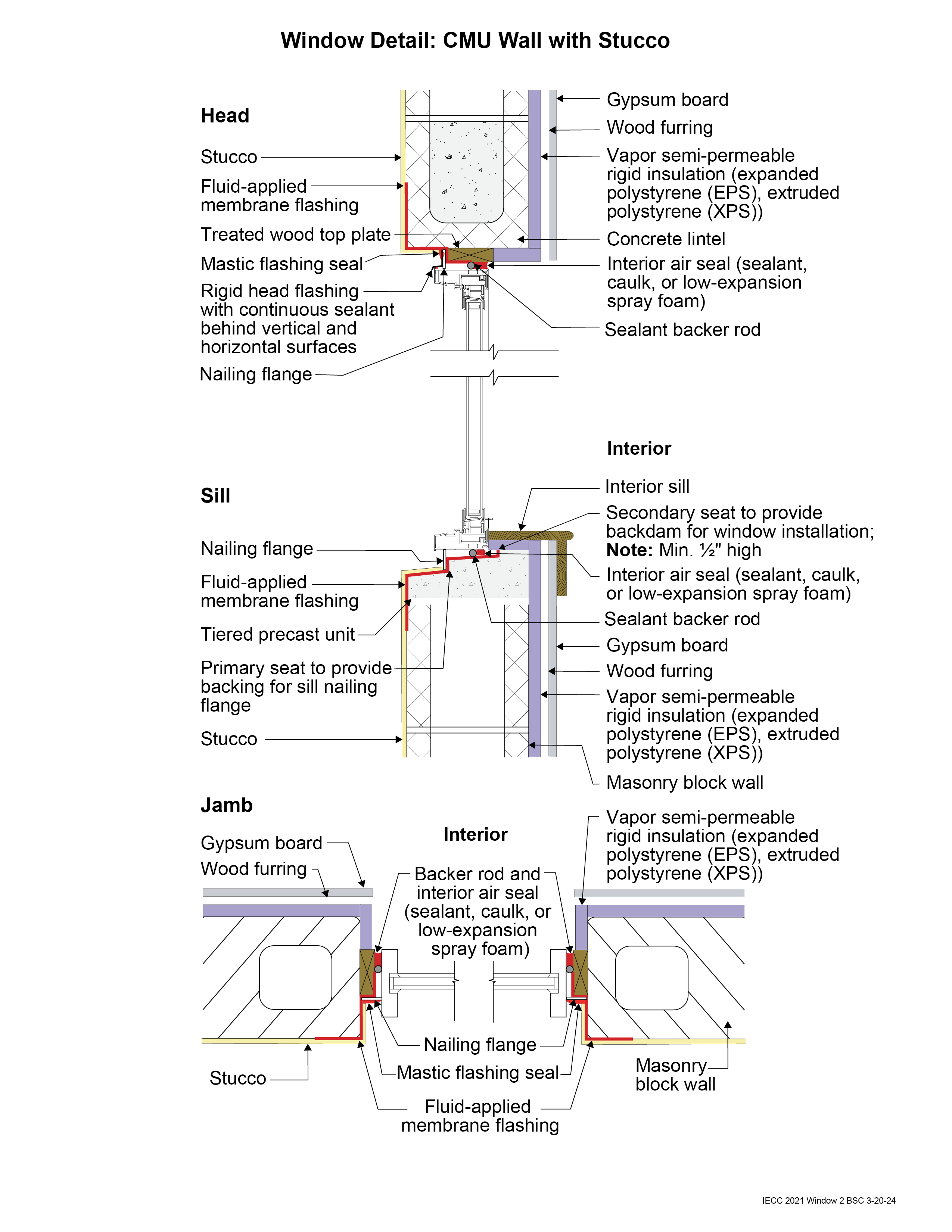
Window Detail 2 - CMU Wall with Stucco
- Note: Always follow the window manufacturer’s installation guidance. Not following manufacturer guidance may void the warranty.
- This is a “mass/storage wall” where rainwater is controlled by the stucco that is directly adhered to the CMU. This is not a “drained wall”. Any water that passes through the stucco is stored, absorbed, and redistributed within the wall assembly and then dries to the exterior or interior or both.
- The window openings are drained to the exterior of the wall.
- The window rough opening is flashed to the face of the CMU with a fluid-applied membrane flashing. The fluid-applied membrane flashing is applied to the rough opening inwards at least past the point where the interior air seal is located around all sides of the frame. This creates water-resistant surfaces inside the cavity between the window flanges and the interior air seal, in case any water gets behind the flanges. The window flanges (head and jambs only) are flashed to this fluid-applied membrane using a mastic flashing seal or self-adhered flashing membrane. Note the tiered precast unit at the window sill opening. This provides drainage to the exterior of the wall. The window is installed using shims just like with a wood-framed sill. The secondary seat, or backdam, of the precast sill should be located far enough to the interior to allow space between it and the window so that shims can be adjusted during installation, and to allow the interior air seal backer rod and sealant to be installed. A sill can be made of treated lumber as an alternative to the tiered precast sill. The sill should still be sloped for drainage.
- It is vital that the mastic flashing seal at the window head and jamb flanges is carefully detailed. There is no mastic flashing seal over the window flange at the sill. This is to allow any water that may get past the head or jamb flanges to drain back out.
- Backer rod for the interior air sealant should be installed after the window is installed, leveled, and shimmed. Use correctly sized backer rod.
2021 IECC Window Detail: Framed Wall with Plywood or OSB Sheathing, a WRB, and Siding (Wood, Fiber Cement, Aluminum or Vinyl, or Stucco)
Notes
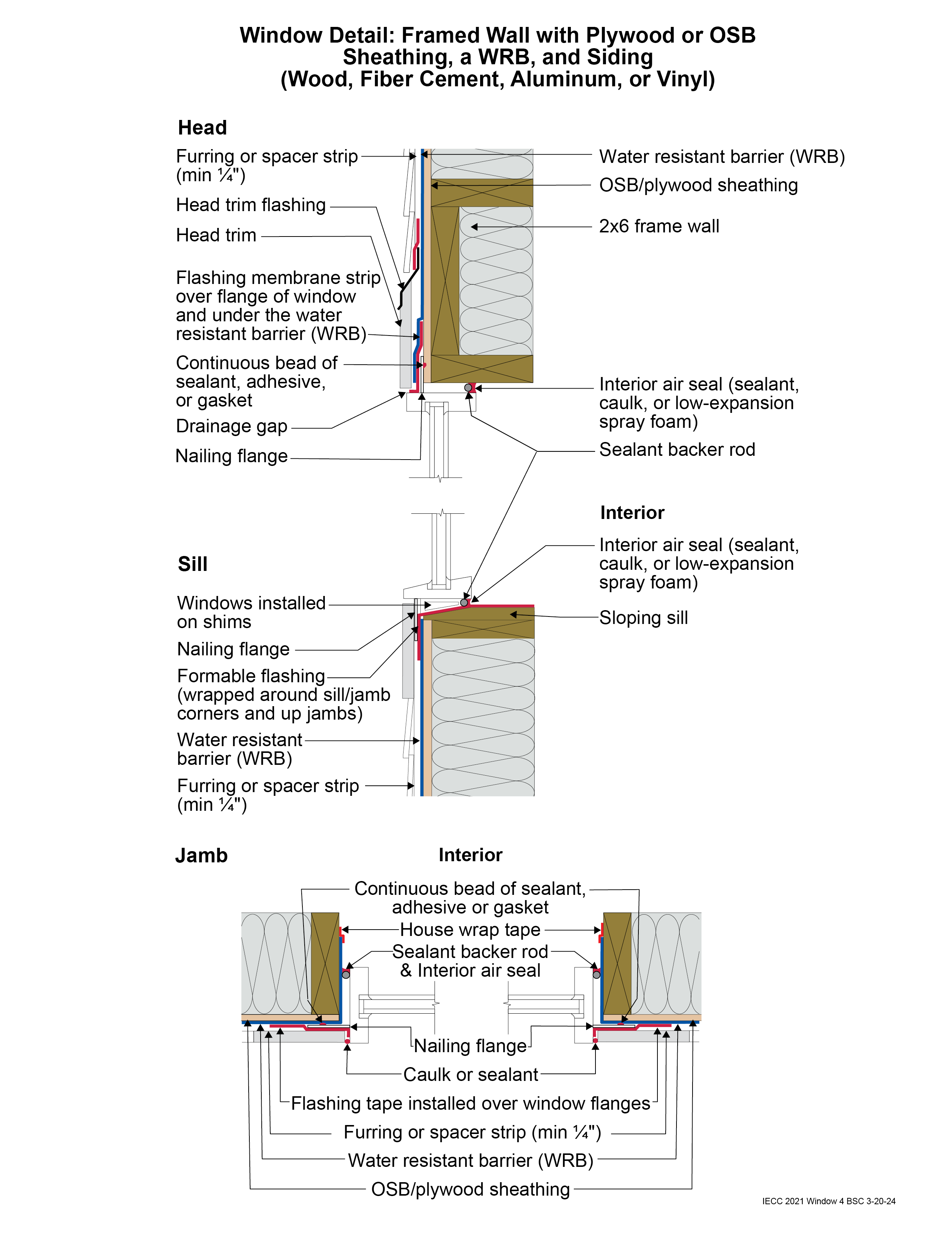
Window Detail 4 - Framed Wall with Plywood or OSB Sheathing, a WRB, and Siding (Wood, Fiber Cement, Aluminum or Vinyl, or Stucco)
- Note: Always follow the window manufacturer’s installation guidance. Not following manufacturer guidance may void the warranty.
- This is a “drained wall”. Drainage occurs between the siding and the water control layer or water resistant barrier (WRB) in the gap created by furring which is installed vertically over the water control layer (WRB) at stud locations. In the case of a stucco wall, the drainage plane is a drainage mat rather than furring gaps.
- The window openings are drained to the water control layer (WRB).
- The rough opening at the window sill is sloped and flashed with a formable flashing.
- The upper portion of the head trim flashing goes under the furring and is taped directly to the WRB with flashing tape. The furring is “cut through” by the head trim flashing, so that the furring below the flashing (behind the head trim) is separate from the furring above the flashing (behind the siding). During construction, the head trim is installed first on short strips of furring. It is flashed directly to the WRB as described above. The rest of the furring is installed with the siding. In the case of a stucco wall, the drainage mat would be treated in similar fashion to furring: the head trim flashing would go under the drainage mat and be taped directly to the WRB with flashing tape.
- Note the gap between the head trim and the top of the window assembly frame. This gap allows water to drain and allows the bottom of the trim to dry out more easily. If installed without this gap, capillary action can draw water into the tight space between the head trim and the window assembly frame. Note also the gap between the siding and the head trim flashing, which serves the same purposes.
- Consider installing rigid head flashing (rigid head flashing is not shown in the schematic). Rigid head flashing is similar to the head trim flashing shown in the schematic, but it goes over the top of the window frame instead of over the head trim. This is required by some manufacturers. It should be installed against the head nailing flange and over the top of the window frame. The vertical and horizontal portion of the flashing should be sealed directly to the window frame and flange with sealant. The red flashing membrane strip shown overlapping the head nailing flange in the schematic would now overlap the rigid head flashing. Use rigid head flashing with a drip edge to guide water away from the window assembly.
- Backer rod for the interior air sealant should be installed after the window is installed, leveled, and shimmed. Use the correct size backer rod.


