

Scope
Install properly lapped flashing around window and door openings to direct water out, not into the wall cavity.
- Install rigid, flexible, or fluid-applied pan flashing at sills.
- Install window or door.
- Install side flashing that extends over the pan flashing.
- Install top flashing that extends over the side flashing.
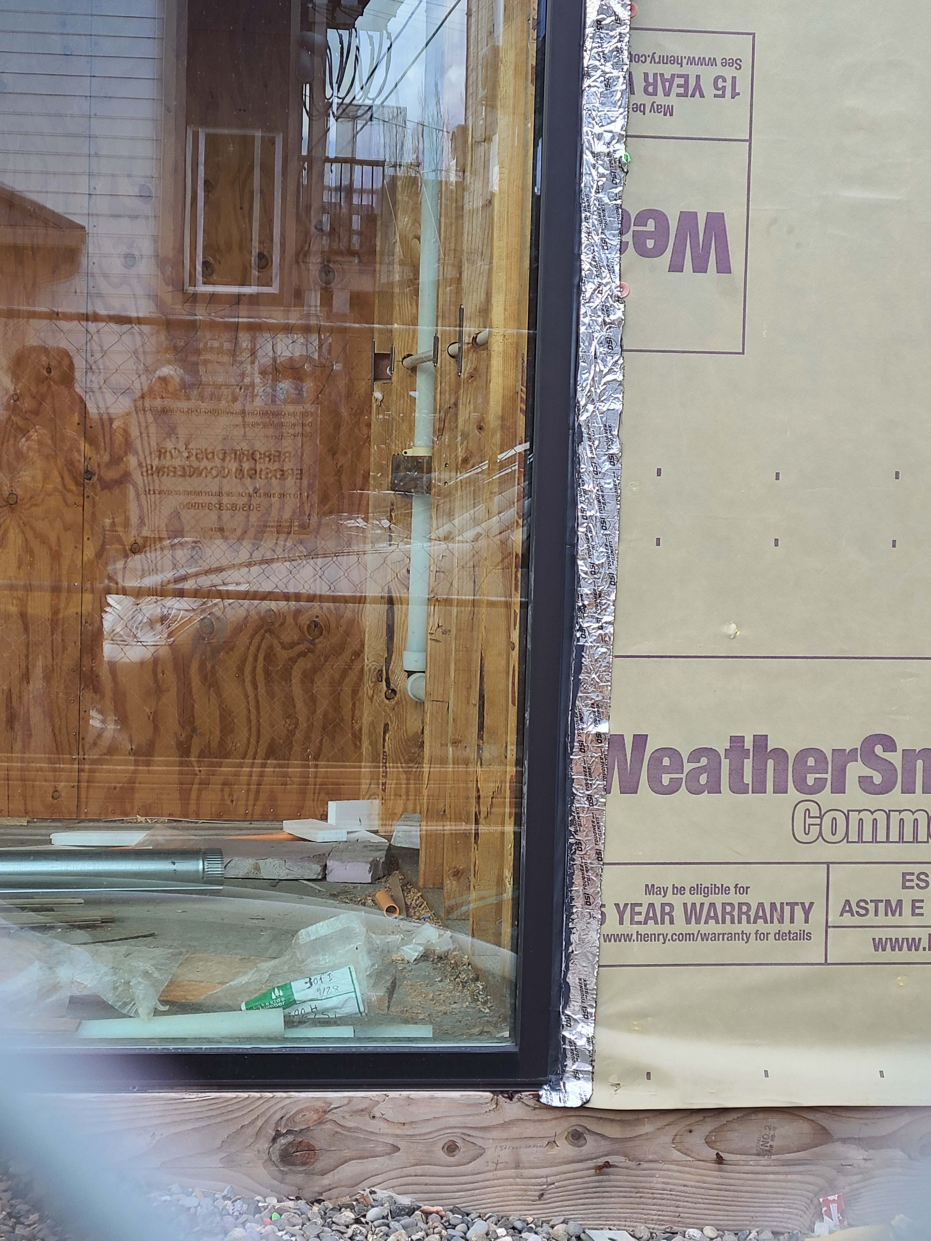
- Properly integrate all flashing with the drainage plane layer (which could be house wrap, taped weather-resistant sheathing, a liquid-applied coating, or another approved material).
See the Compliance tab for links to related codes and standards and voluntary federal energy-efficiency program requirements.
Description
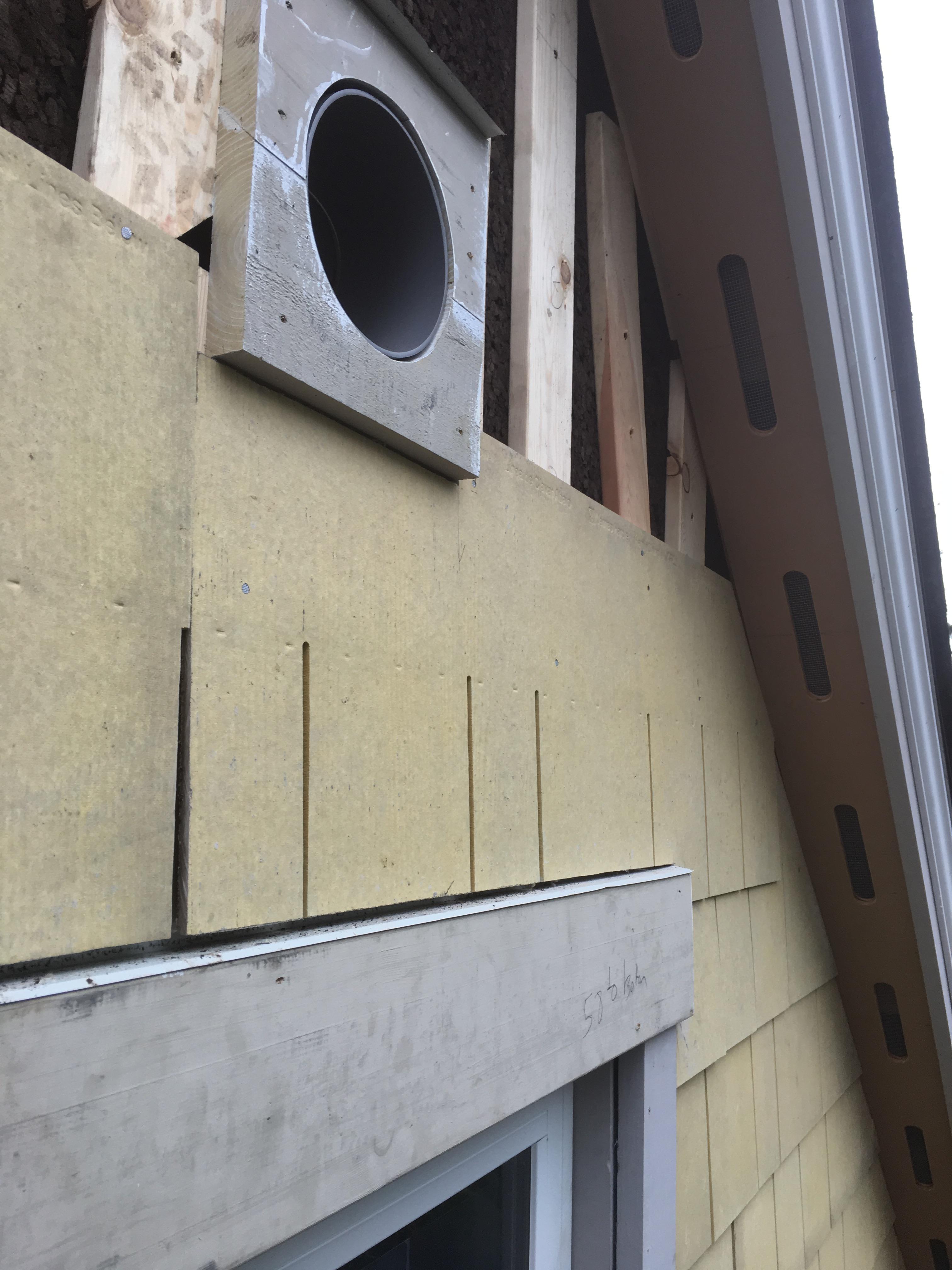
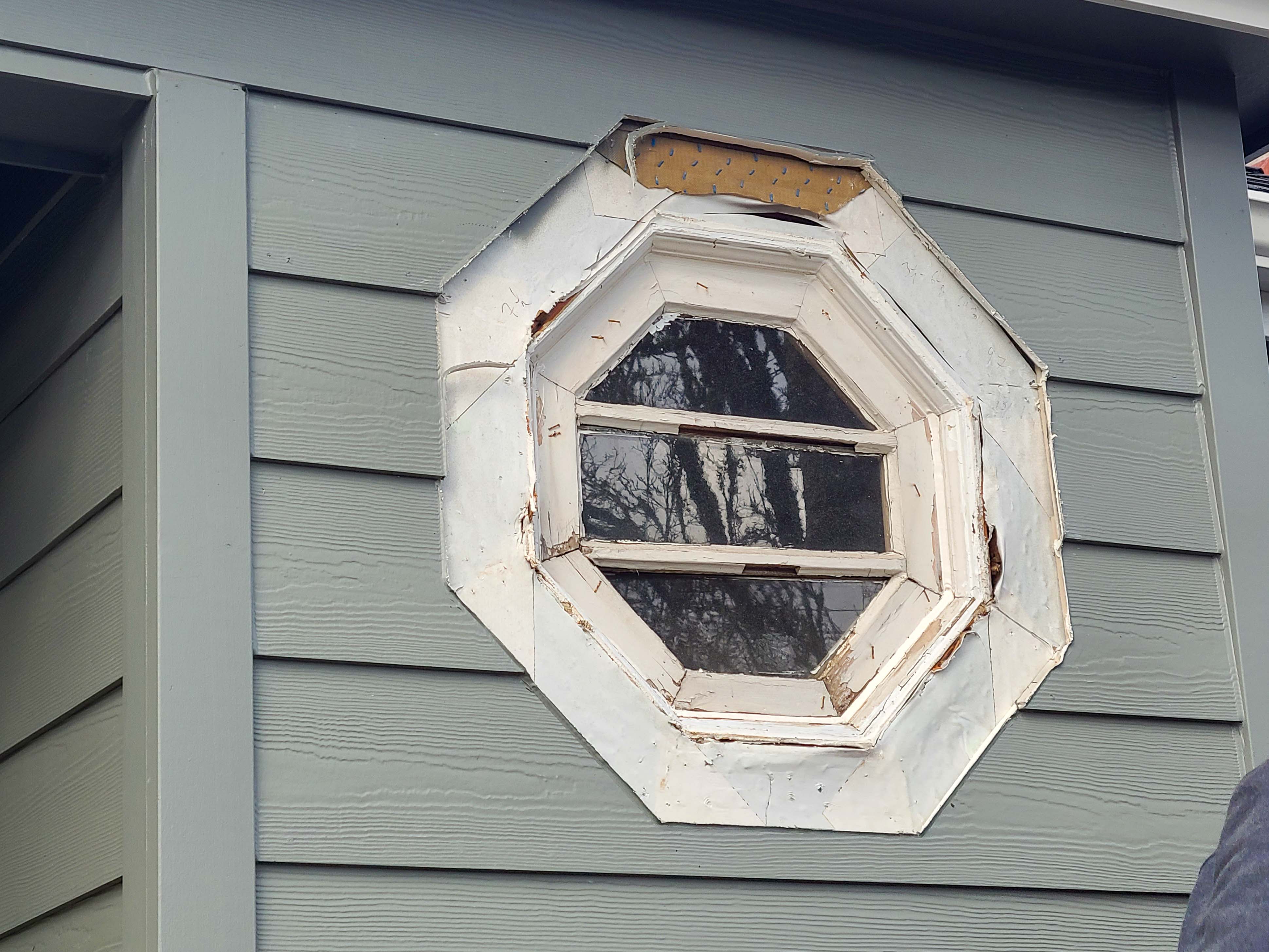
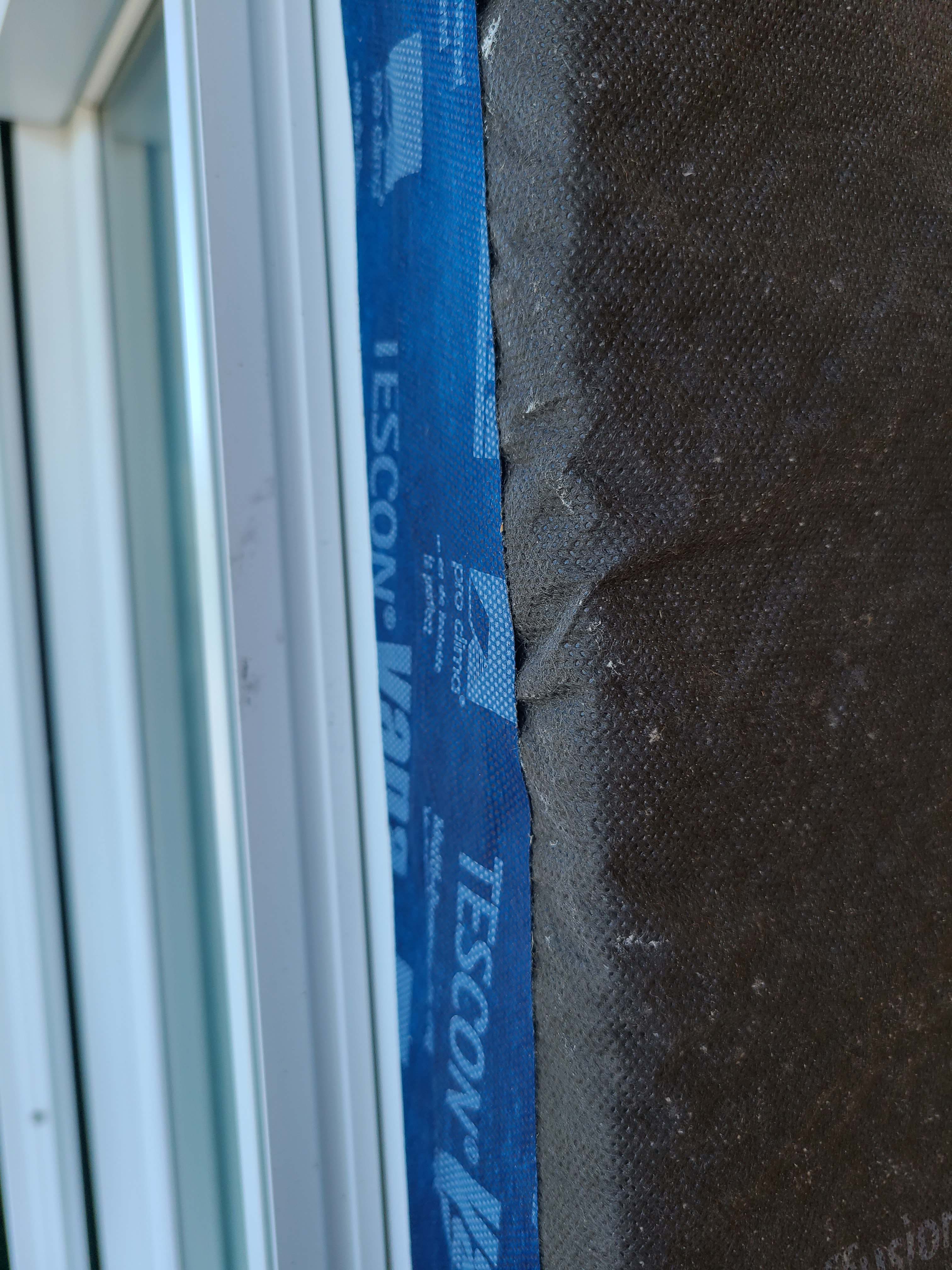
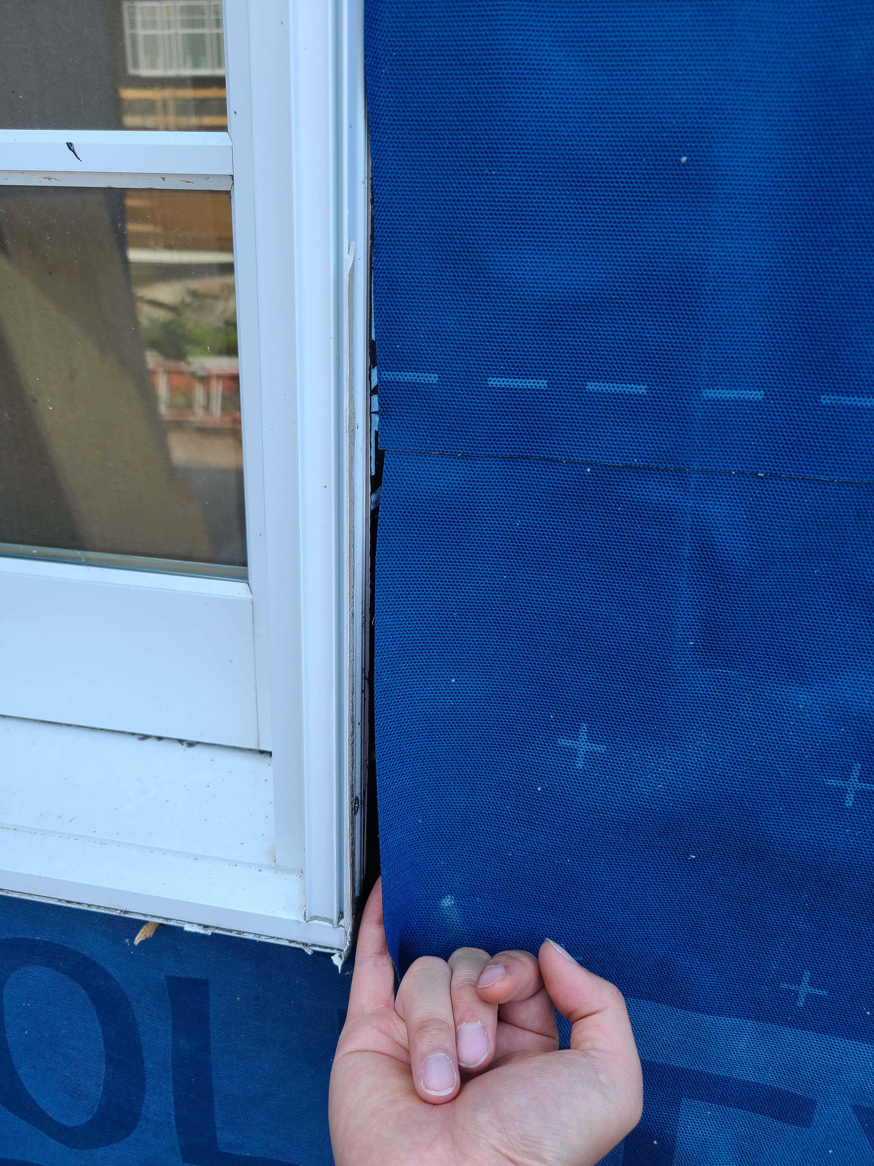
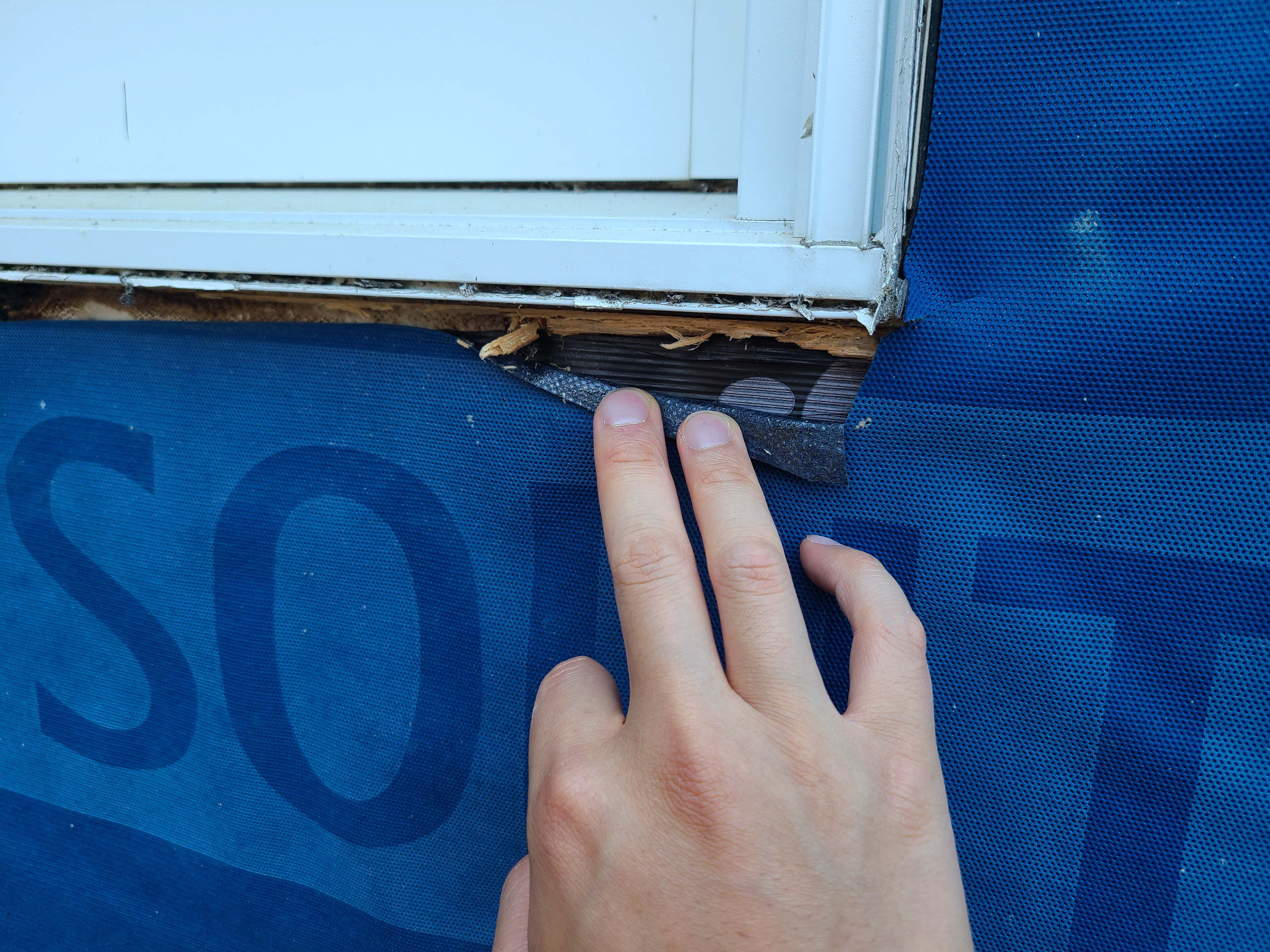
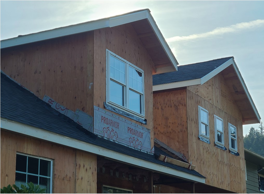
Windows and doors are an interruption in the wall’s house wrap or insulated sheathing drainage plane and thus are a vulnerable spot for water leakage. Many homes suffer from water intrusion around doors and windows, often not discovered until considerable damage has been done within the wall. The wall framing around windows and doors must be protected from any water that finds its way behind the siding at these locations and the water must be directed out to prevent damage to the rest of the wall. Properly installed flashing that is integrated with the other elements of the wall can help prevent water damage.
Flashing materials may be installed by insulators, framers, or subcontractors or vendors hired specifically to install the windows and doors. This task should be included in the contract for the appropriate trade depending on the workflow at the specific job site.
Other Considerations: When designing the home, walls and doors should be located under overhangs or porch roofs whenever possible; these features protect against rain and snow and also minimize unwanted solar heat gain by blocking out the high summer sun.
Air and water leaks around doors during high wind events can contribute to building failures; see the Climate tab for more information.
How to flash windows and doors
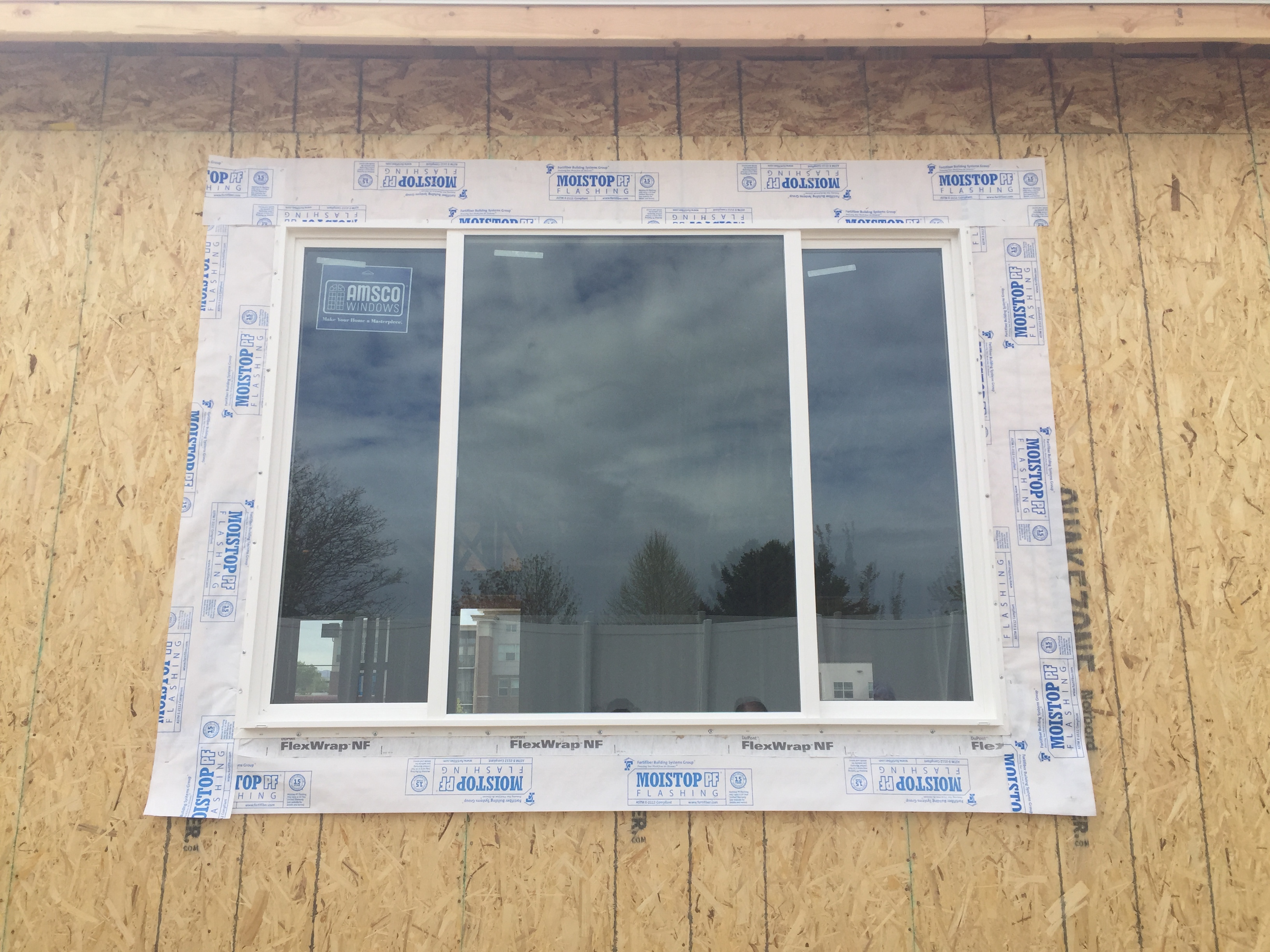
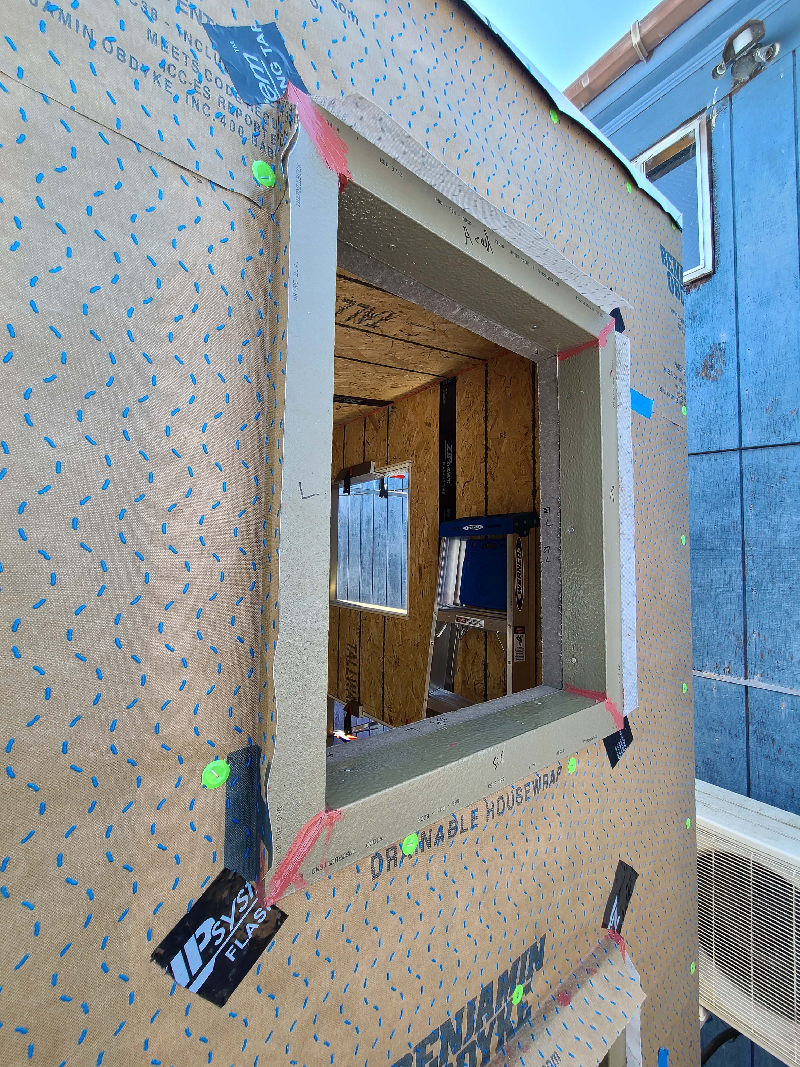
- Cut the house wrap covering the rough opening in the shape of a modified "I." See Figure 1.
- Fold the side and bottom flaps into the window opening and secure.
Above the window opening, cut a head flap. Fold it up to expose the sheathing and loosely tape it in place out of the way.
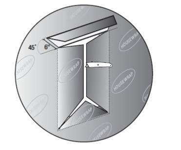
Figure 1. Cut an I in the house wrap over the window rough opening. (Source: Building America Best Practices Series Volume 12.)
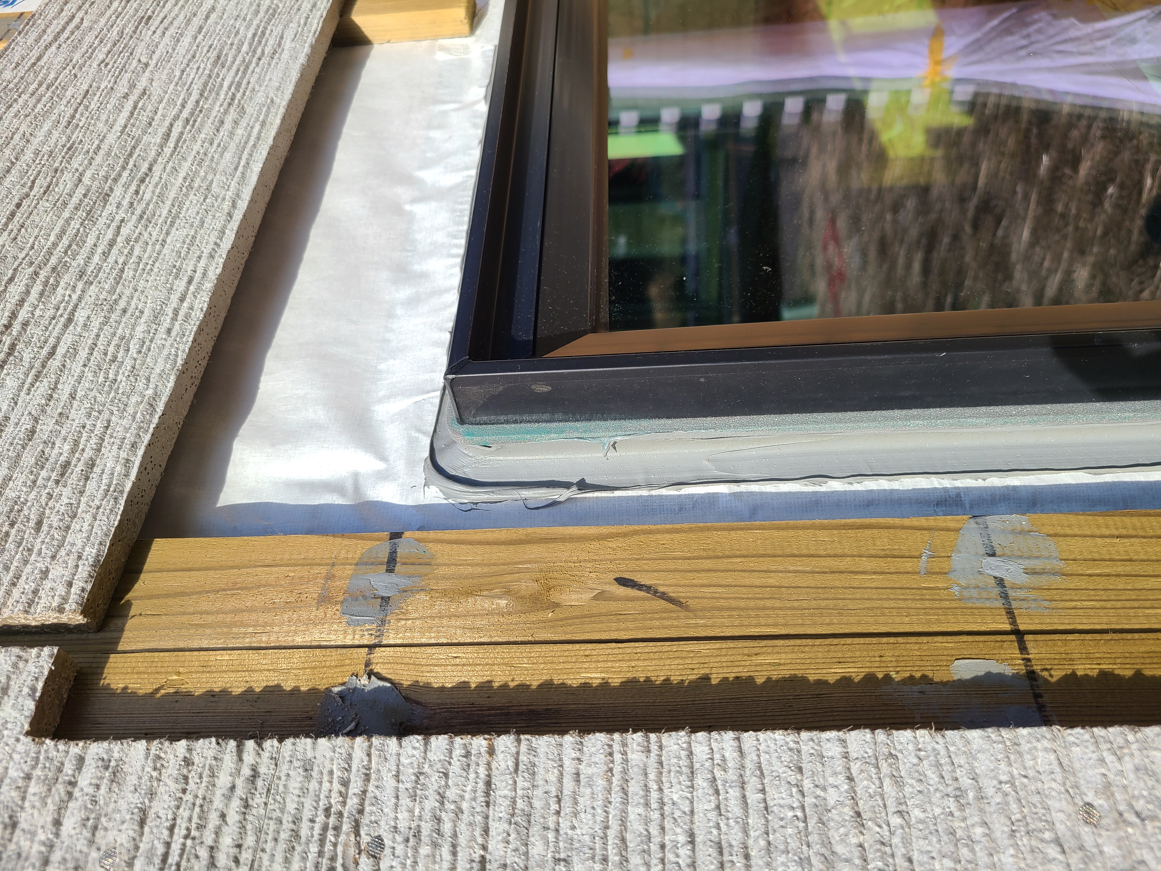
Install back dam and self-adhesive flashing at sill. Tape the corners. See Figure 2.
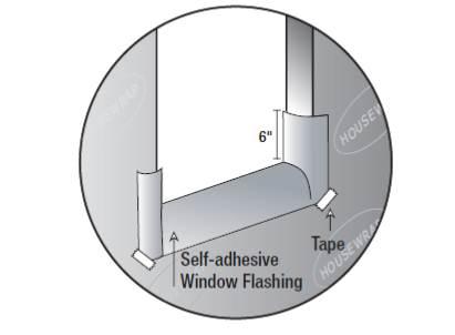
Figure 2. Install self-adhesive sill flashing in the window rough opening. (Source: Building America Best Practices Series Volume 12.) For pan or sill flashing, use formable flashing, a stretchable self-adhered membrane that bends at corners so one continuous piece can be used to cover the bottom and sides of the sill.
- First install a back dam consisting of a strip of wood or beveled siding nailed along the back (inside) edge of the rough opening (over the flap of housewrap). Sloped pans are required if the sill depth is greater than 6 inches according to ASTM E2112-07.
- Cover this with the membrane. Begin pressing in the middle of the sill and work toward the sides, removing adhesive covering strips as you go. Make sure to press the membrane tightly into the corners to avoid tears later when the window is installed.
Other options for pan flashing include self-adhered non-elastic membrane (see Figure 3), which must be cut and patched at corners, two-piece rigid manufactured pan flashing, which comes with a built-in back dam that must be protected from breakage during window installation, or asphalt-based liquid flashing which is applied with a paint brush or roller.
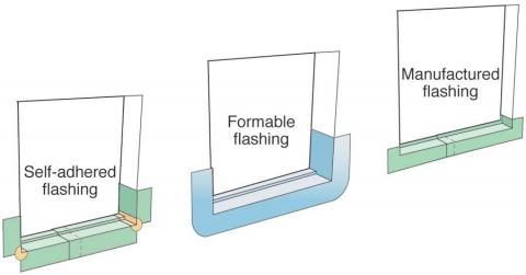
Figure 3. Three types of window pan flashing with back dams. (Source: Pan Flashing for Exterior Wall Openings.) Caulk the outside edges of the head and side jambs and install the window. See Figure 4.
- Do not caulk across the sill.
- Install the window plumb, level, and square following manufacturer’s specifications.
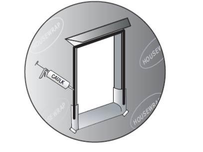
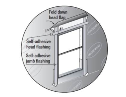
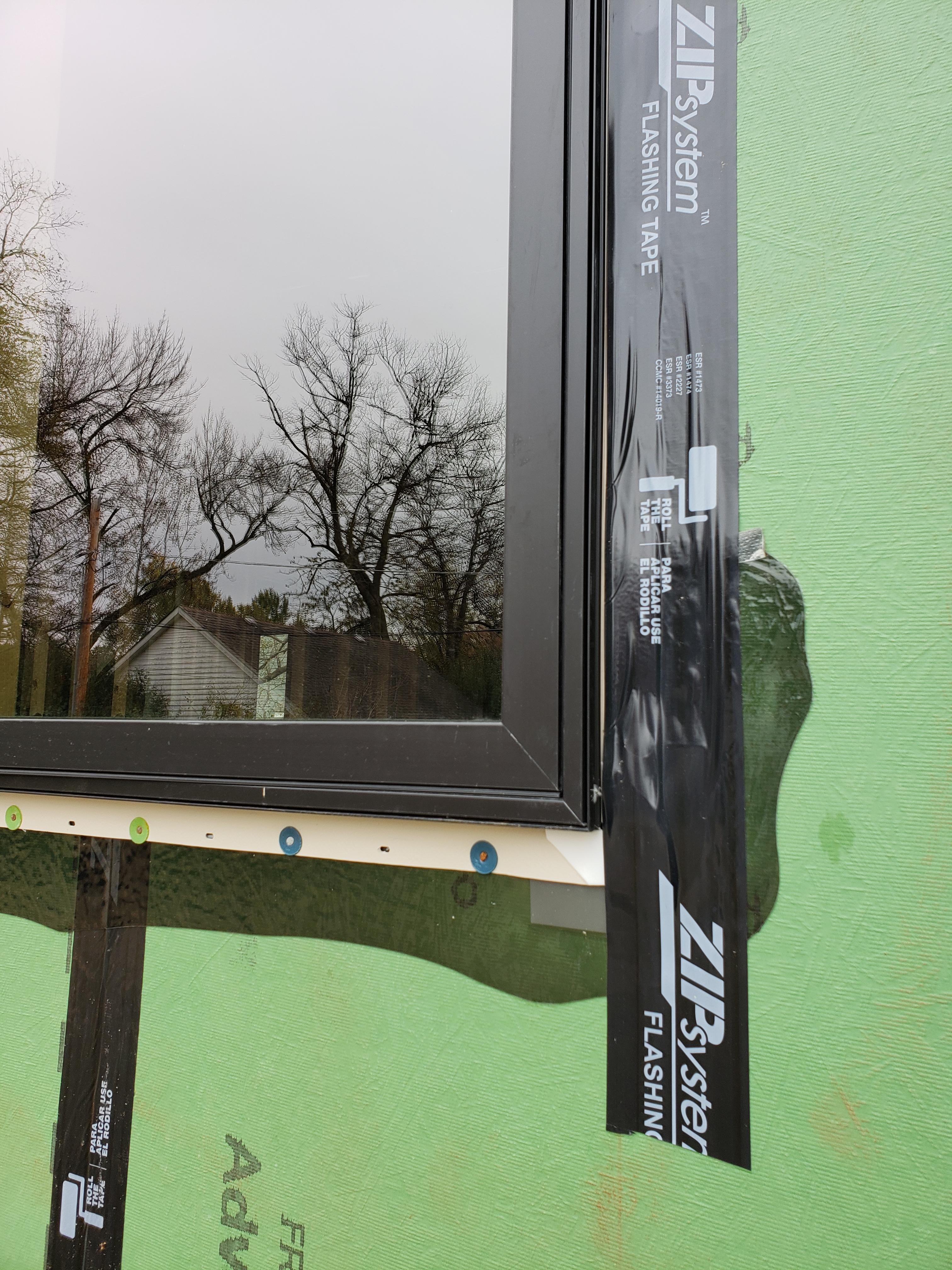
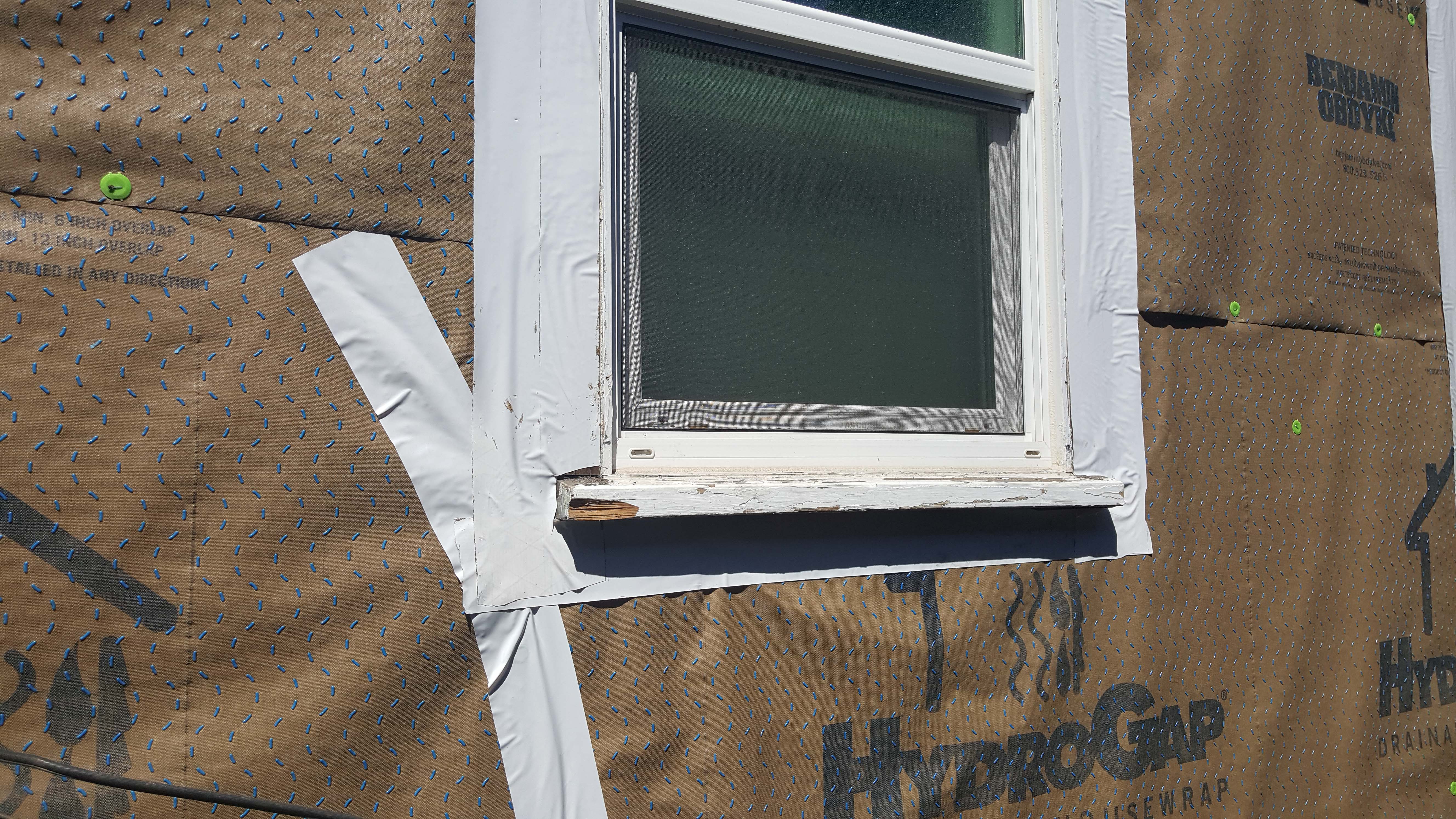
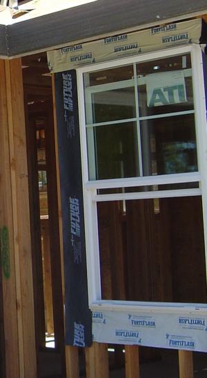
Figure 4. Caulk the top and sides of the window rough opening, but not the bottom. (Source: Building America Best Practices Series Volume 12.) Install jamb and head flashing. See Figure 5.
- Install self-adhesive jamb flashing extending 4 inches above the top of the head flange and even with the bottom of the sill flashing.
- Install self-adhesive head flashing extending 1 inch beyond the jamb flashing.
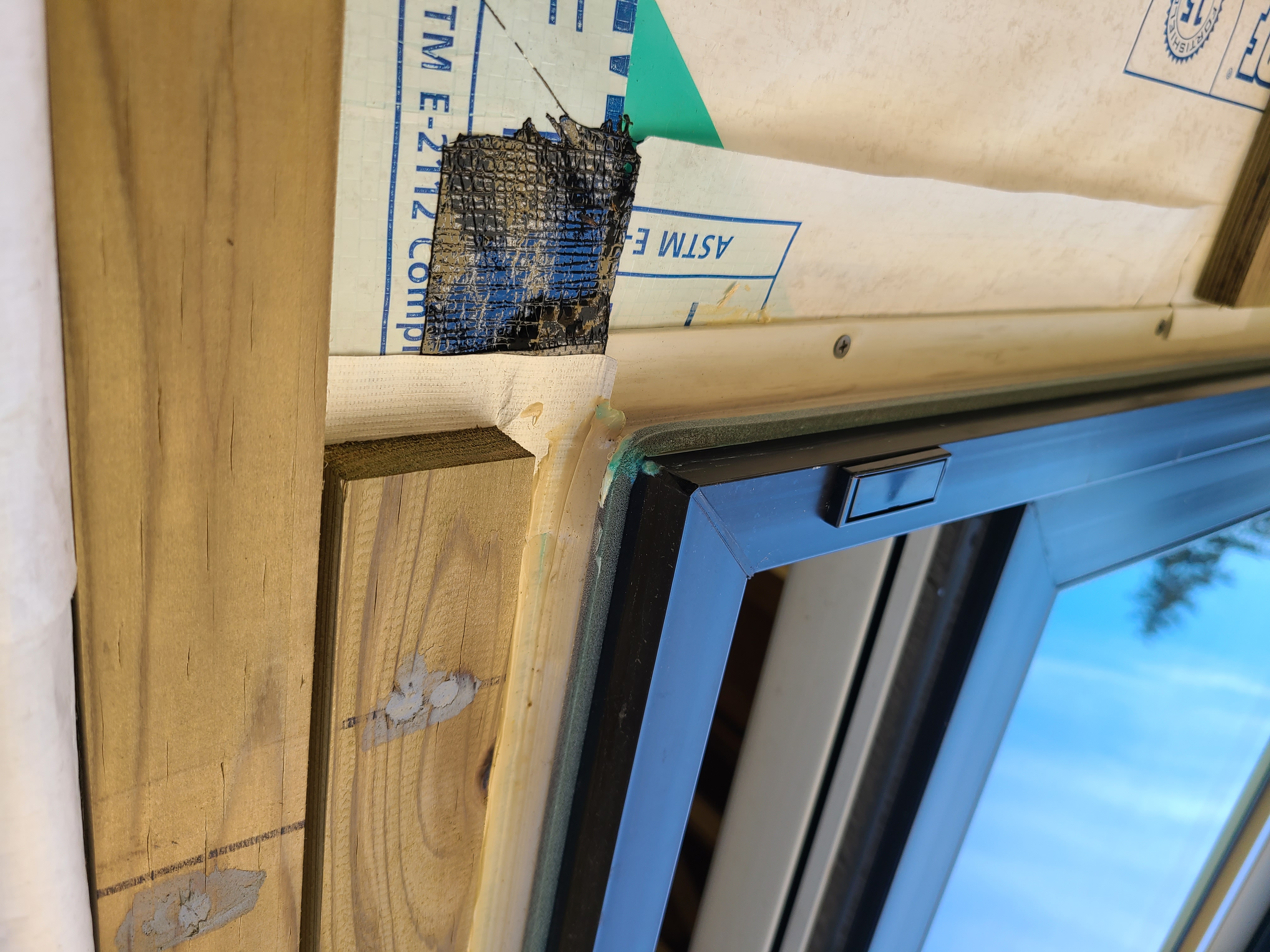
- Unfold the housewrap and lay over the head flashing. Tape bottom edge of housewrap across the top window flange and tape down corner seams of housewrap. See Figure 5.
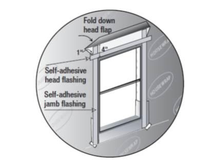
Figure 5. Flash the sides and top of the window. (Source: Building America Best Practices Series Volume 12.) On the interior side of the window, seal the gap between the window and the rough opening with backer rod or non-expanding foam and caulk. See Figure 6.
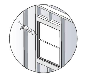
Figure 6. Air seal the rough opening around the window from the inside. (Source: Building America Best Practices Series Volume 12.) Install trim that has been painted or primed on all sides. Above top trim, install cap flashing that extends past trim. Cover top edge of cap flashing with adhesive membrane strip. Cover top edge of membrane with sheathing tape. See Figure 7.
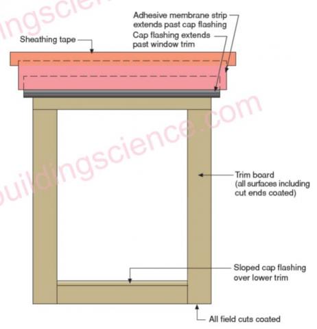
Figure 7. Install trim and cap flashing above the window. (Source: READ THIS: Before You Design, Build or Renovate.)
How to Flash a Door
- Flash the door head and jambs as described above for windows or in accordance with the door manufacturer’s instructions.
- For sill flashing, see the door manufacturer’s instructions.
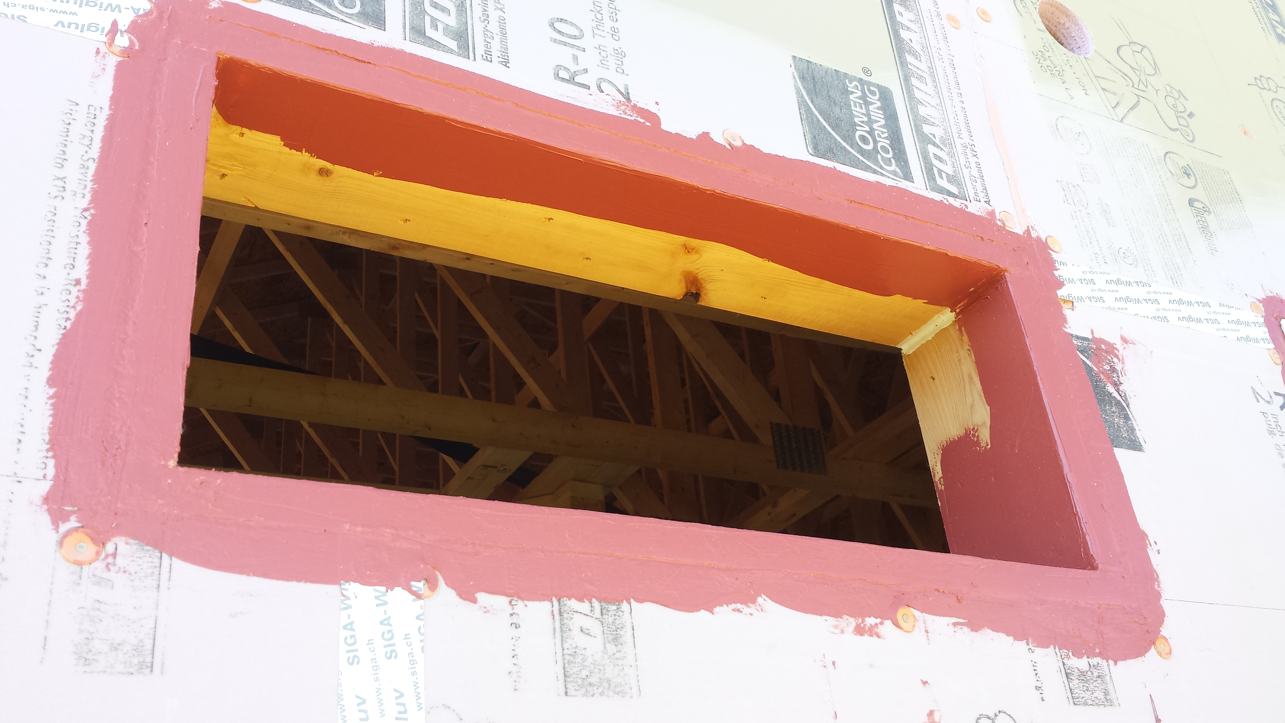
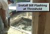
For houses with concrete slab floors, form a seat in the concrete slab to act as a “pan flashing.” See Figure 8.
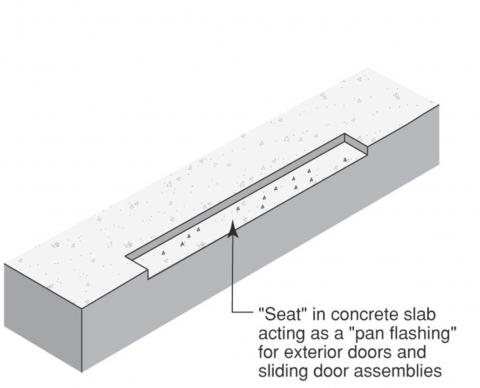
Figure 8. A seat is formed in the concrete slab to act as pan flashing for a door. Install pan flashing that is integrated with the housewrap. ASTM E2112-07 recognizes several flashing materials and methods, including single-piece sill pans formed from rigid sheet metal (see Figure 9) , multi-piece sill pans formed from rigid sheet metal or plastic, flexible membrane, or combinations of rigid corners connected by flexible membrane.
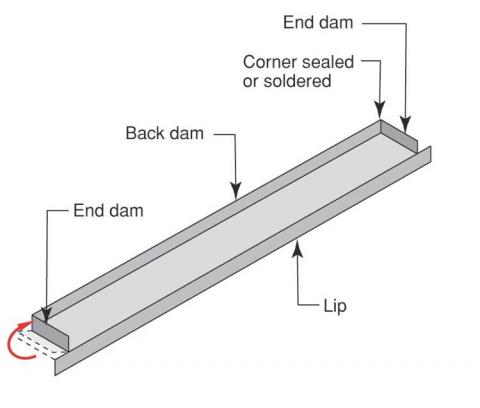
Figure 9. Sheet metal pan flashing for doors. (Source: Pan Flashing for Exterior Wall Openings.)
Ensuring Success
Visually inspect the window and door flashing before siding is installed to ensure that flashing is correctly installed and correctly integrated with sheathing and house wrap to direct water out and away from wall cavities.
Region
Hurricane and High Wind Zones
In areas prone to hurricanes and high winds, here is a summary of steps that can be taken to improve the storm resistance of exterior doors based on the detailed information provided below and in the cited documents by FEMA and others:
- All exterior doors on homes in hurricane areas should be pressure and impact rated or protected by a system that is pressure and impact rated, according to the Insurance Institute for Business & Home Safety (IBHS 2019).
- Doors should be properly flashed, weather stripped, air sealed, and set in pan flashings designed to resist the entry of wind and wind-driven rain.
- For increased disaster resistance in coastal and high wind areas, install exterior doors to swing outward rather than inward. Weather stripping should be installed on the interior side of the doors to minimize decay.
- Consider designing the home’s entry with a vestibule and outer and inner entry doors. Construct the entry with durable water-resistant flooring.
- Install water-resistant flooring at all entryways.
- Doors, door framing, and door hardware should be made of water-resistant, corrosion-resistant materials.
- Exterior doors should meet U-factor requirements for the home's climate zone, as required by local building codes. Please see the Compliance Tab for more information.
- FEMA P-499 “Technical Fact Sheet No. 6.1: Window and Door Installation,” provides some best-practice approaches that can be taken to reduce water infiltration. Pan Flashing, weather stripping, and threshold seals are discussed. The Solution Center guide Fully Flashed Window and Door Openings and the “Tech Note: Window and Door Flashing: Code Requirements and Best Practices” by Home Innovation Research Labs provide additional detailed instructions for installing window and door flashing.
In all areas where buildings are constructed, windows and doors tend to be more vulnerable to damage than other portions of a building’s envelope. In coastal areas where high winds, windborne debris, and wind-driven rain are common and often intense their vulnerabilities are more pronounced (FEMA P-762 2009). Air leaks around doors can allow in wind during high-wind events, contributing to an increase or decrease in internal pressures that can contribute to building failures (FEMA P-762 2009). Flashing is required by the IRC Section R703.8 to prevent moisture from entering the wall system.
Water leakage around windows and doors is also quite common but because the effects of water leakage are often subtle, the full effects of water leakage are often not readily apparent. Water-resistant siding materials like vinyl and veneer can hide moisture damage in the sheathing caused by rainwater entry for years. Leakage or water entry, due to inadequate or improperly installed flashing, weather stripping, or weather-resistant barriers, can allow water to enter a building’s interior even when the structure of the window or door remains intact. Water intrusion can cause rot and fastener corrosion that can weaken the window or door frame or the wall framing itself. Leakage can also cause damage to interior finishes and facilitate mold growth (FEMA P-762 2009).
Windows and doors can fail if they are not strong enough to resist wind pressures from a high-wind event or if forces exerted on the doors or windows exceed the strength of their anchorage. When strength is inadequate, the window or door’s glazing or frames fail; when anchorage is inadequate, the entire door or window unit can be torn from its mounting. As wind speeds increase due to storm strength in Category 2 or weak Category 3 levels, failures of these elements become more frequent. Wind pressure increases resulting from the failure of windows and doors can significantly increase (in some cases doubling) the wind forces working to blow the roof off or blow out exterior walls.
FEMA P-762 Local Officials Guide to Coastal Construction provides the following guidance on window and door leakage (excerpted). Hurricanes and coastal storms can pose significant problems from water infiltration due to wind-driven rain. Leakage can occur between the door or window and their frames and between the door/window frames and the walls onto which they are mounted. Coastal storms such as tropical storms and hurricanes generate winds that may approach or exceed the wind speeds observed during design wind events. As such, these winds generate high-wind pressures on the outsides of the buildings, exploiting any vulnerability around doors and windows and allowing water to enter buildings. Further, leakage rates typically increase with greater wind speeds. While the amount of water entry that can result from leakage around windows and doors will typically be much less than the amount of water entry that can result from a breach in the building envelope, actions can and should be taken to help reduce leakage around doors and windows. These actions are often code-plus or best-practices approaches.
Code Requirements for Window and Door Leakage - Proper door and window construction is critical to reducing water infiltration. Section R613.4 of the IRC and Section 1714.5.1 of the IBC require windows and sliding doors to be certified per AAMA/ WDMA/CSA 101/I.S.2/A440, Standard/Specification for Windows, Doors, and Unit Skylights. Hinge doors must be certified per ASTM E330, Standard Test Method for Structural Performance of Exterior Windows, Doors, Skylights, and Curtain Walls by Uniform Static Air Pressure Difference. Both standards specify wind-pressure and water-leakage criteria that must be met in order to comply with code requirements. In general, water-leakage tests are conducted at much lower differential pressures (typically 20 percent) than the pressures used to determine the strength of the glazing, window, or door assembly. This implies that some water entry through doors and windows should be anticipated during an event that produces design wind pressures and wind-driven rain.
Reducing Window and Door Leakage - FEMA 499, Technical Fact Sheet No. 6.1: Window and Door Installation, Window and Door Installation, provides some best-practices approaches that can be taken to reduce water infiltration. Pan flashing (i.e., flashing under window sills), weather stripping, and threshold seals are discussed. Other actions can be taken to reduce the potential for water entry. These include:
- Vestibules. Designing a vestibule, or double-doored entry, to protect a door entry is one method of managing water infiltration problems. Through this approach, both the inner and outer doors can be equipped with weather stripping, and the vestibule itself can be designed to tolerate water. For example, water-resistant finishes (e.g., concrete or tile) can be specified, and the floor can be equipped with a drain. As a result, a secondary layer of protection is provided for the primary entrance (via the vestibule and vestibule door).
- Door swing. Out-swinging doors offer an advantage compared to in-swinging door assemblies. With out-swinging door assemblies, the weather stripping is located on the interior side of the door, where it is less susceptible to degradation than the exposed weather stripping on in-swinging door assemblies. Also, some interlocking weather-stripping products are available for out-swinging door assemblies that provide better performance than those used on in-swinging door assemblies.
- Finish selection. One design approach to deal with leakage is to avoid running carpet (or other finishes that can be damaged by water) entirely to the edge of walls that contain a large amount of glazing. Instead, a strip of water-resistant material (such as tile) could be specified along the wall so, if leakage occurs, the potential for damage to interior finishes and contents is greatly reduced.
Window and Door Assembly Capacities - Window and door assemblies must be strong enough to withstand wind pressures acting on them and be fastened securely enough to transfer those wind pressures to the adjacent wall. Pressure failures of doors or windows can allow glazing to fracture or glazing frames or supports to fail. Anchorage failures can allow entire door or window units to be ripped from their walls. Either type of failure results in the failure of the building envelope and allows wind and water into the building.
Code Requirements for Strength and Anchorage - Both the IRC and IBC contain specific requirements for the wind resistance of windows and doors. Section R613.3 of the IRC requires that exterior windows and doors be designed to resist the wind pressures specified in Table R301.2(2). Table R301.2(2) lists positive and negative wind pressures for C&C for various locations within the building. Areas near roof and wall edges and areas near corners, where turbulence creates localized high wind pressures, must be designed for higher loads. Table R301.2(2) is based upon Exposure B conditions for buildings with a mean roof height of 30 feet or less. Table R301.2(2) pressures must be multiplied by factors listed in Table R301.2(3) for different mean roof heights and exposures.
The IBC requirements are similar but are less prescriptive and more performance based. While the IRC has tabulated wind pressures, Chapter 16 of the IBC specifies acceptable methods of calculating wind loads and (in Section 1603.1.4) requires that construction documents list wind pressures for C&C.
IBC Section 1405.12, Exterior Windows and Doors, requires windows and doors to be tested in accordance with IBC Section 1714.5, which lists two methods of establishing wind resistance. Section 1714.5.1 allows doors and windows to be labeled per AAMA/WMDA/CSA 101/I.S.2/A440; Section 1714.5.2 allows doors and windows to be tested per ASTM E330. The latter option has additional requirements regarding glass supports and framing that are outlined in Section 2403 and pressure ratings for Section 1714.5.2 are outlined in Chapter 16, the structural design chapter of the IBC.
AAMA/WMDA/CSA 101/I.S.2/A440 lists design test pressures of 15, 25, 30, and 40 psf. Windows and doors used in areas where wind pressures are greater than 40 psf need to be tested per ASTM E330. For residential construction, local officials must ensure that products proposed are adequate to resist the C&C loads of Table R301.2(2). For engineered construction, the designer should specify wind pressures required for windows and doors and should base them on C&C loads from either Chapter 6 of ASCE 7-05 or Chapter 16 of the IBC.
Section R613.8.1 of the IRC requires that windows and glass doors be anchored in accordance with published manufacturer’s recommendations. The manufacturer’s installation instructions should match those used when the units were tested and certified. Substitute anchorage systems are allowed if they provide equal or greater anchoring performance as demonstrated by accepted engineering practice.
IRC contains Figures R613.8(1) through R613.8(8) [Figures R609.7.2(1-8) in 2021 IRC.] that provide minimum anchorage details. The details require windows and doors to be anchored in accordance with the published manufacturer's recommendations. Substitute anchoring systems used for substrates not specified by the fenestration manufacturer shall provide equal or greater anchoring performance as demonstrated by accepted engineering practice. IBC Section 1405.12.1 requires windows and doors to be installed in accordance with approved manufacturer’s instructions.
To minimize issues related to corrosion, the use of fiberglass or vinyl frames are recommended for buildings located within 3,000 feet of an ocean shoreline. The use of stainless-steel frame anchors, fasteners, and hardware is also recommended within these areas.
Pests
Damp wood attracts termites and carpenter ants and makes wood framing and sheathing easier for rodents to gnaw through. Window and door flashings that are properly integrated with the wall weather-resistant barrier will help to keep the wall assemblies drier and discourage pest entry.
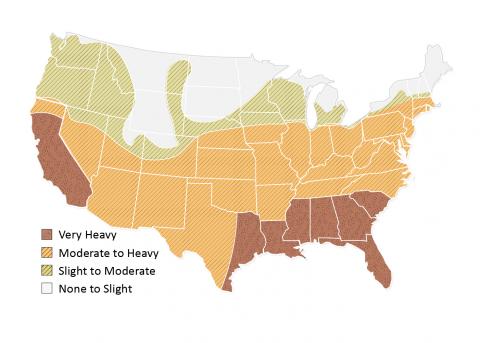
In areas where severe termite or insect infestation problems exist (see termite infestation map, Figure 1), wood frames should either be treated or should be constructed with wood that is naturally insect- and rot-resistant. Shims and bucks should be pressure-treated. Since some pressure treatment increases the moisture content of framing, the use of material that is kiln dried after treatment is suggested to control shrinkage.
In areas where insect infestation problems exist, metal door assemblies are recommended. If concrete, masonry, or metal wall construction is used to eliminate termite problems, wood used for blocking or bucks should be treated, or naturally insect- and rot-resistant species of wood should be used (FEMA P-762 2009).
Training
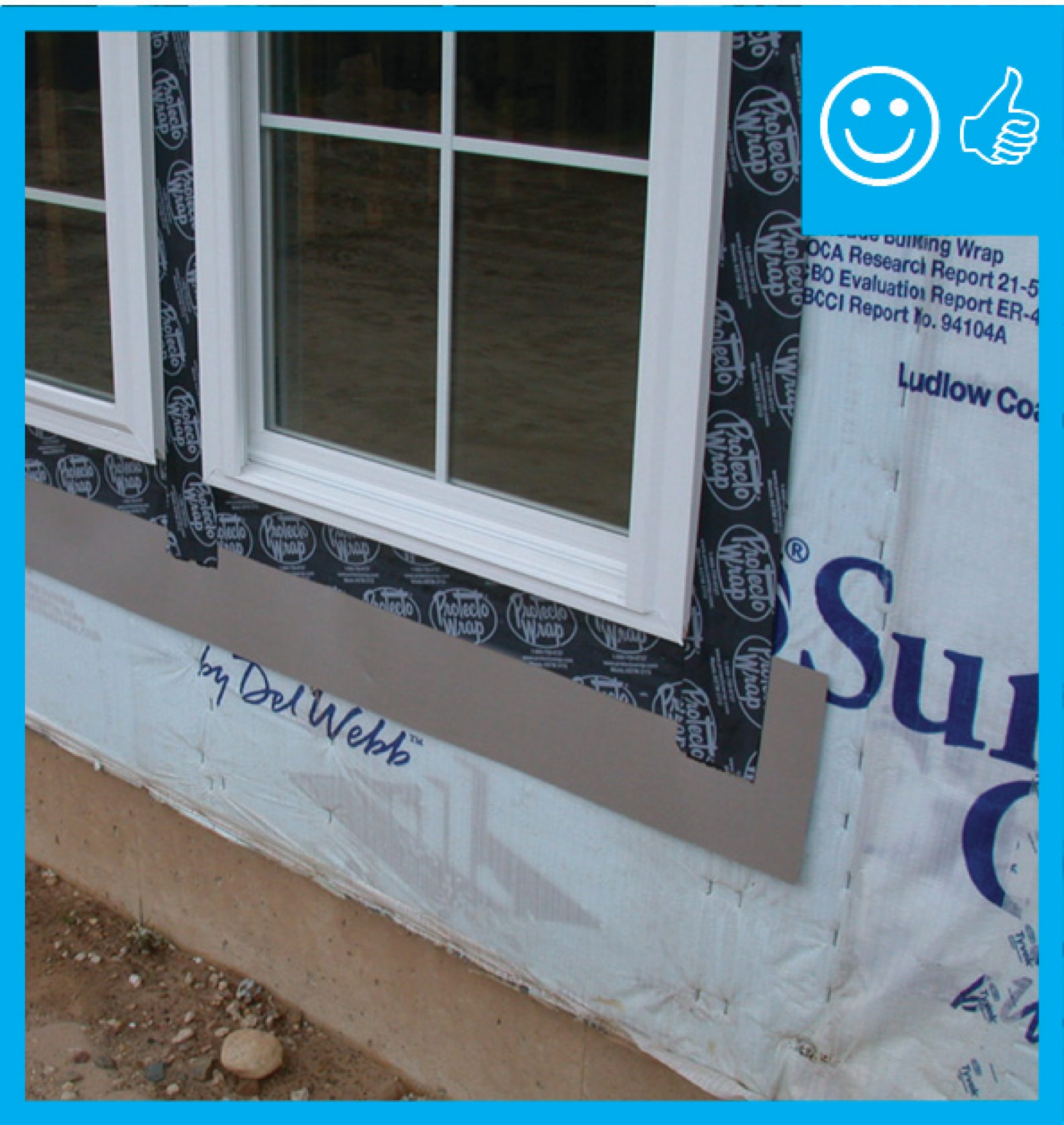
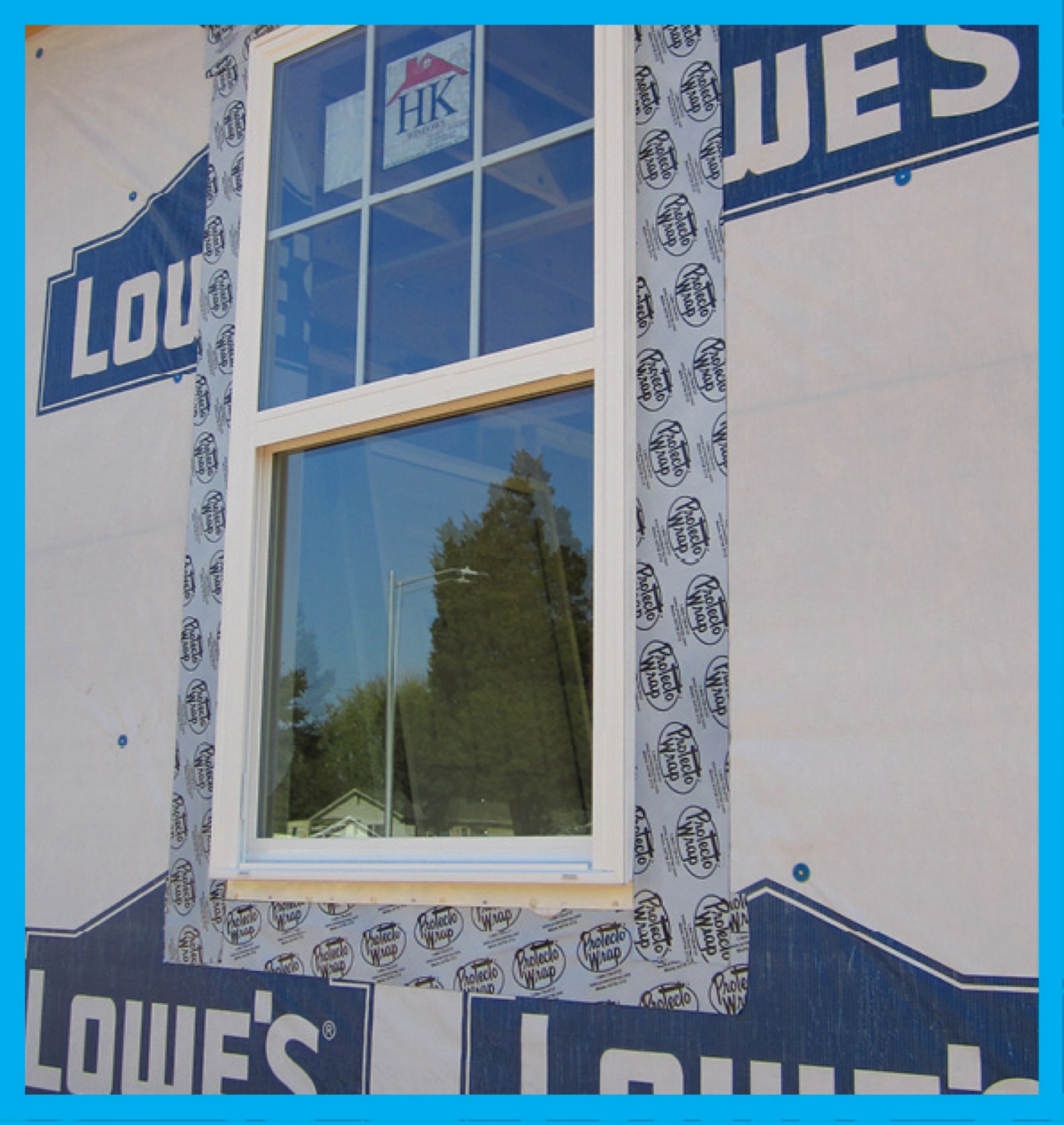
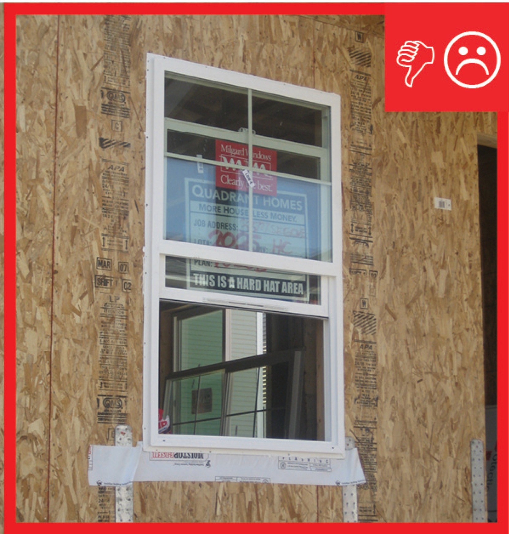
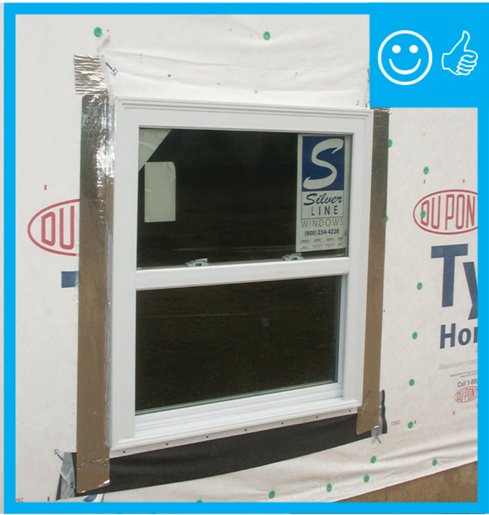
Right and Wrong Images
Source
Guide describing details that serve as a visual reference for each of the line items in the Water Management System Builder Checklist.
Source
Guide describing details that serve as a visual reference for each of the line items in the Water Management System Builder Checklist.

Source
Guide describing details that serve as a visual reference for each of the line items in the Water Management System Builder Checklist.
Source
Guide describing details that serve as a visual reference for each of the line items in the Water Management System Builder Checklist.
Source
Guide describing details that serve as a visual reference for each of the line items in the Water Management System Builder Checklist.
Source
Guide describing details that serve as a visual reference for each of the line items in the Water Management System Builder Checklist.

Source
Source
Source
Source
Source
Guide describing tools for island and hurricane-prone communities on redevelopment and rehabilitation of homes to prepare for future natural disasters.
Source
Source
Source
Source
Source
Source

Source
Source
Source
Source

Source
Source

Source
Source
Source
Source
Source

Source

Source
Source
Source
Source
Source
Videos


Retrofit
SCOPE
Retrofit rough openings of windows and doors with new flashing prior to the installation of new or rehabilitated windows and doors.
- Evaluate building conditions for hazards and damage; correct as needed before proceeding.
- Identify concerns (water infiltration, air leakage, heat loss) and rank them to determine the project goals.
- If appropriate, remove the existing windows or doors, as well as adjacent trim and cladding, and prepare the rough openings for new flashing as outlined in the Description tab.
For more information on conditions that may be encountered when working with walls in existing homes, see the assessment guide on walls, windows, and doors.
See the U.S. Department of Energy’s Standard Work Specifications for more on installing and replacing windows. Follow safe work practices as described.
DESCRIPTION
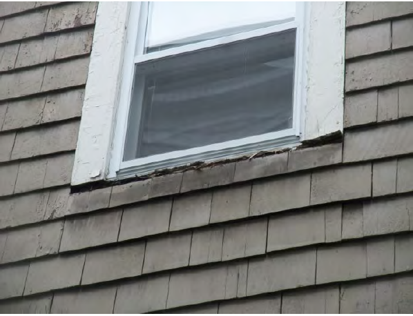
Unless a home owner is pursuing a deep energy retrofit that involves removal of the cladding to add exterior insulation, window and door retrofits often do not address water management of the rough opening, apart from simply caulking the new window or door to the existing trim, which is left in place. While not best practice, this limited type of window retrofit (which does not address the rough opening) is often carried out successfully, especially if the trim is painted and in good condition, the sill trim is sloped to the exterior, and the wall retains its ability to dry after the retrofit. The risk of water problems such as leaking and rot increases at windows with high exposure to wind and rain, damaged or improperly sloped sills, and when the wall’s ability to dry is decreased (with the addition of cavity insulation, for example). Figure 1 shows a new window installed in a wall with a failed rotting window sill. Air and water leakage will likely soon occur around this window if it hasn’t already started.
The best practice when replacing windows is to remove the trim and flash the rough opening for drainage and durability per the concepts outlined in the Scope and Description tabs. There are several Solution Center guides describing measures that can be taken to improve water management, comfort, and energy efficiency with windows, ranging from repair and refurbishment to adding storm windows, to full replacement. Also see the report “Measure Guideline: Wood Window Repair, Rehabilitation, and Replacement” by Building Science Corporation.
How to Flash Existing Windows and Doors
- Evaluate building conditions for hazards and damage that should be corrected before proceeding such as the presence of lead paint or water intrusion from sources other than the window.
- Identify existing window and door performance concerns (water infiltration, air leakage, heat loss) and rank them to determine the project goals so that the appropriate retrofit measures may be selected, from minor repairs to full removal and replacement.
- If full removal is appropriate, remove the existing windows or doors as well as adjacent trim and cladding, and prepare the rough openings with new flashing in accordance with the steps outlined in the Description tab.
COMPLIANCE
See Compliance tab.
More Info
Case Studies
References and Resources
*For non-dated media, such as websites, the date listed is the date accessed.
Contributors to this Guide
The following authors and organizations contributed to the content in this Guide.
Building Science Corporation, lead for the Building Science Consortium (BSC), a DOE Building America Research Team
Home Innovations Research Labs, lead for the Partnership for Home Innovation (PHI), a DOE Building America Research Team
Sales
Pan Flashing (doors/windows) = Window/Door Water Barrier
Technical Description
Windows and doors interrupt a wall’s water protection layer creating vulnerable spots for leakage. Properly installed flashing is critical and often required by code to stop water intrusion around doors and windows. Pan flashing is an element installed at the sills of windows and doors, the location most vulnerable to water intrusion. It has to integrate with jamb flashing and overlap the wall water barrier below to collect and direct any water that may leak through or around the opening back out to the exterior.
Questions? Comments? Contact our webmaster.