

Scope

Install stucco as an exterior wall cladding over rigid foam insulation with proper preparation to provide water management as well as a sound substrate for the stucco.
- Determine the location of the wall’s water control layer (typically behind the insulation over the exterior sheathing).
- Provide a drainage gap in front of the water control layer.
- Flash all windows, doors, and other penetrations to the water control layer prior to installing the insulation.
- Install stucco cladding per manufacturer requirements.
See the Compliance Tab for links to related codes and standards and voluntary federal energy-efficiency program requirements.
Description
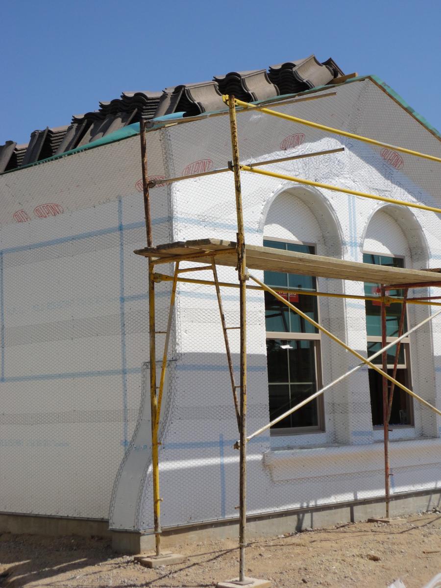
In response to more demanding energy codes, and as occupants and home owners press for more energy-efficient, thermally comfortable, and quiet houses, builders and designers are increasingly considering continuous rigid foam exterior insulation, even in warmer climates (zones 1-3), and with cladding types more common to those warmer climates. (Stucco is the subject of this guide, but please note that adhered stone and tile follow the same principles).
With increased efficiency and comfort, however, also comes an increase in the risk of water-related building failures (such as mold, rot, and odors) because the exterior insulation reduces the energy flow through the wall, which also reduces its capacity to dry. For this reason, it is essential that proper drainage is provided behind cladding materials such as stucco.
Installing stucco cladding over rigid foam insulation requires additional preparation to ensure proper water management as well as a sound substrate for the stucco. This involves determining the location of the wall’s water control layer (typically behind the insulation over the exterior sheathing), providing a drainage gap in front of the water control layer, and flashing all windows, doors, and other penetrations to the water control layer prior to installing the insulation. After the insulation is installed, the stucco cladding may be installed per typical manufacturer requirements. Coordination between the designer or builder and installing subcontractor is required.
With respect to the location of the drainage plane, either over the face of the sheathing (behind the insulation) or at the face of the insulation, the former is far more common than the latter. Indeed, keeping the water control layer at the face of the exterior sheathing means that standard window and door flashing details (and standard installation sequencing) are maintained – windows, doors, and other penetrations are flashed to the water control layer at the face of the sheathing regardless of whether continuous insulation is used or not. When the face of the insulation becomes the water control layer, window and door flashing details must be adjusted accordingly and a different installation sequence must be followed. That said, there are material (and perhaps also labor) cost savings associated with using the face of the insulation as the water control layer (a separate membrane is no longer required).
The following guidance is for installations where 1.5 inches or less of continuous exterior rigid foam insulation is installed under the stucco cladding. Where more than 1.5 inches of continuous exterior rigid foam insulation is installed, additional structural support such as a second layer of structural sheathing (plywood or OSB) may need to be installed over the rigid foam. In this case, the second layer of sheathing must be protected from decay by installing a water control membrane over it with a drainage gap.
How to Install Stucco over Continuous Rigid Insulation
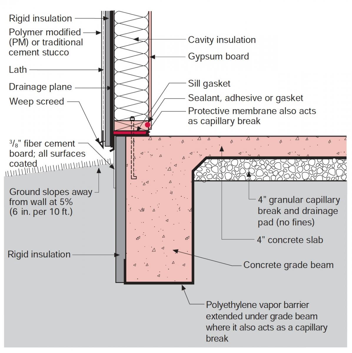
- Determine the location of the wall’s water control layer (the drainage plane). Typically this will be behind the insulation and over the exterior sheathing, but the face of the rigid insulation may also serve as the wall’s water control layer/drainage plane if the joints are taped.
- Install a water control layer (building wrap, self-adhered or fluid-applied membrane) over the face of the exterior sheathing and flash all windows, doors, and penetrations to that layer. See Figure 2. IRC 2018 requires the water control layer to be equivalent to two layers of Grade D paper. Or, if the face of the rigid insulation is to be the water control layer, tape the joints with acrylic sheathing tape or self-adhered membrane (which is recommended at the inside and outside corners for better adhesion) and flash the windows, doors, and penetrations to the face of the insulation.
- Provide a drainage space in front of the water control layer:
- If the water control layer (drainage plane) is behind the insulation and over the exterior sheathing, the drainage space can be achieved by installing a layer of textured house wrap over a water control membrane. Alternately, cap nails can be used as spacers between the water control layer and the rigid insulation. The installer should use his or her professional judgment to determine the number of cap nails and the spacing required to provide a clear drainage plane.
- If the water control layer (drainage plane) is the face of the insulation, the drainage space can be achieved by installing a layer of textured building wrap over the insulation.
- For buildings that exceed two stories, are architecturally complex, or are built in locations that receive more than 20 inches of rain per year, the drainage space described above is insufficient, and a drainage mat (minimum ¼ inch thick) is recommended in lieu of the cap nail spacers or textured building wrap. Note that if drainage mat is used, it either needs to have an integral facer (typically a geotextile fabric) or a paper-backed lath should be used to prevent the pores of the drainage mat from becoming blocked with the subsequent application of the stucco.
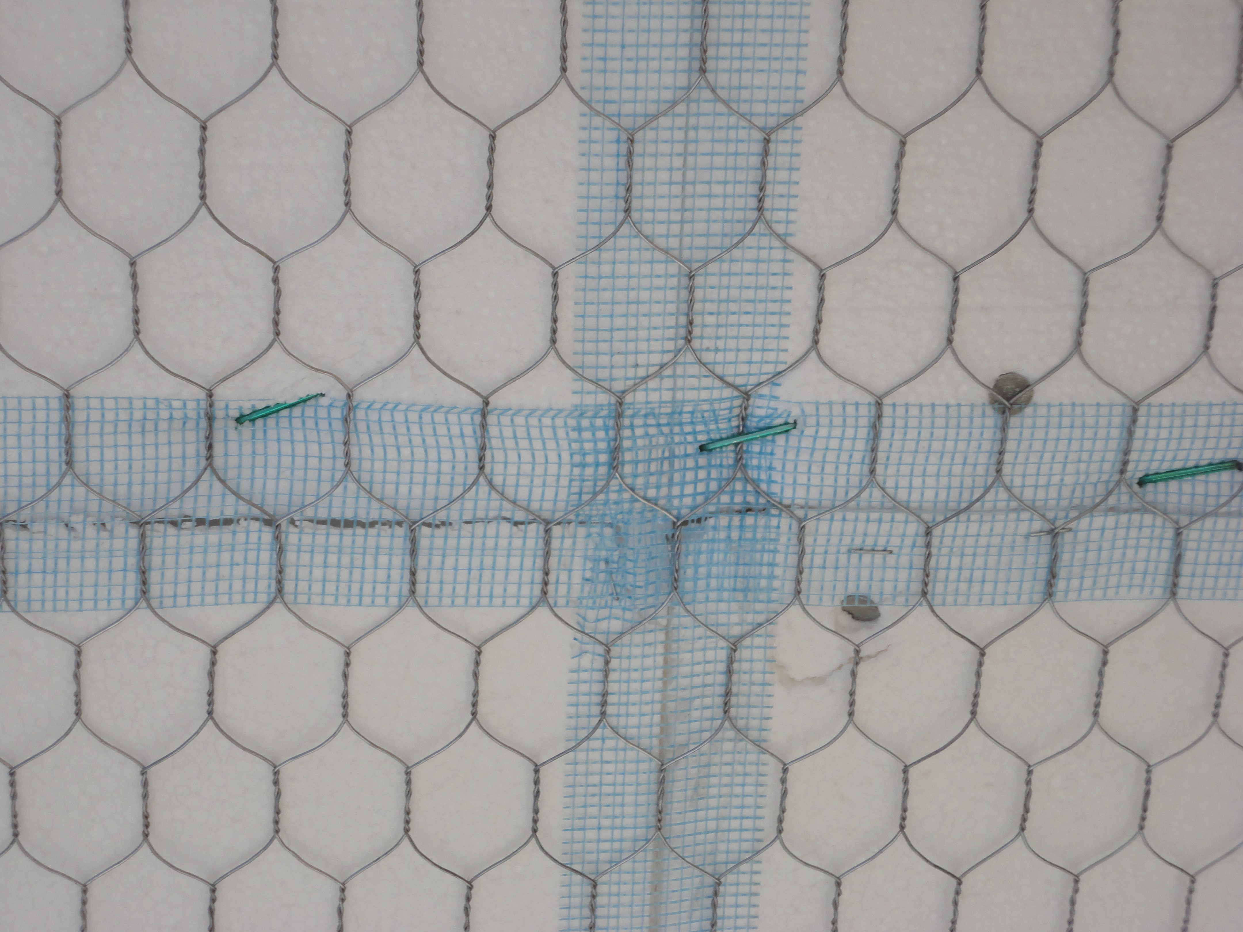
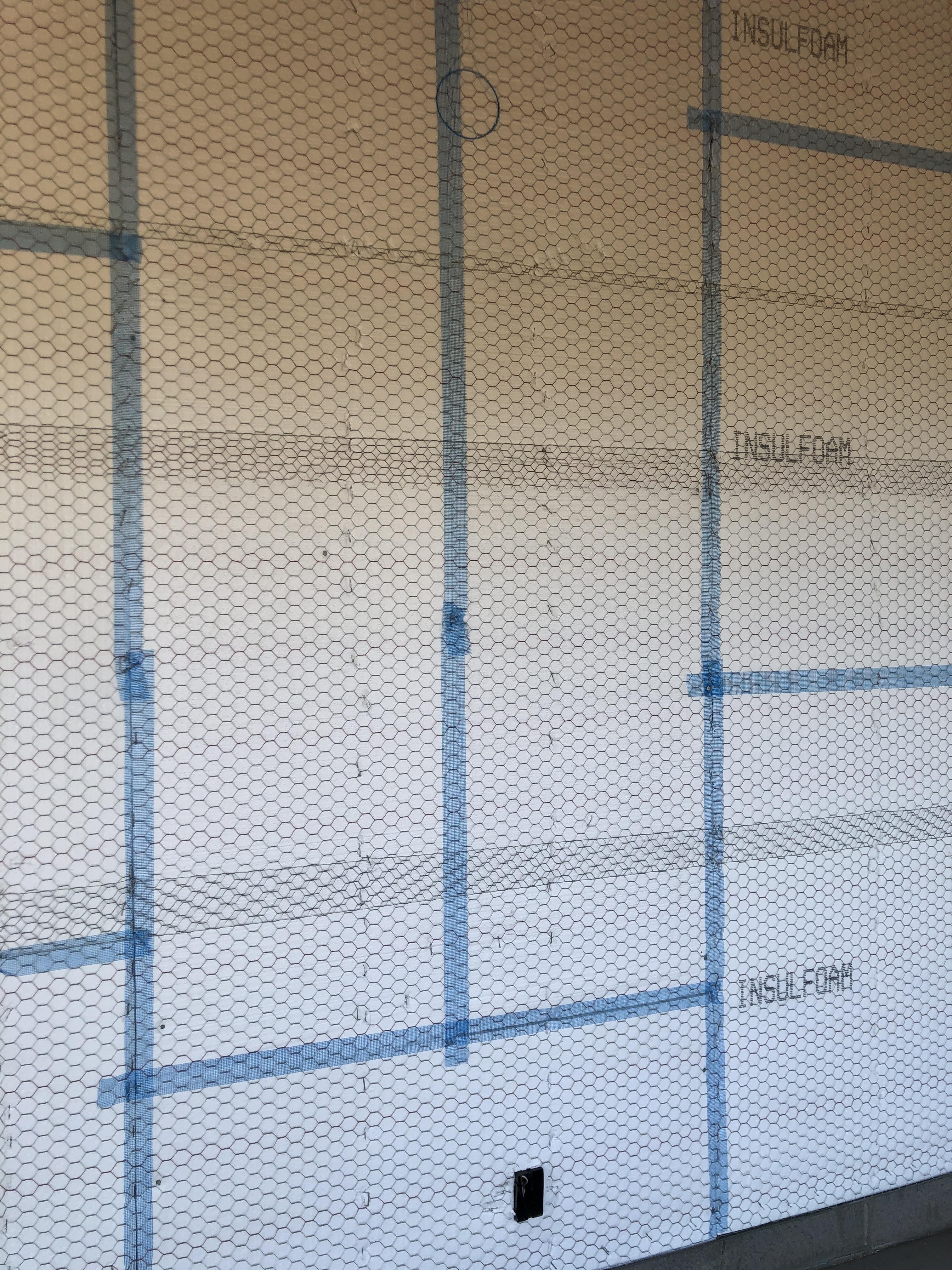
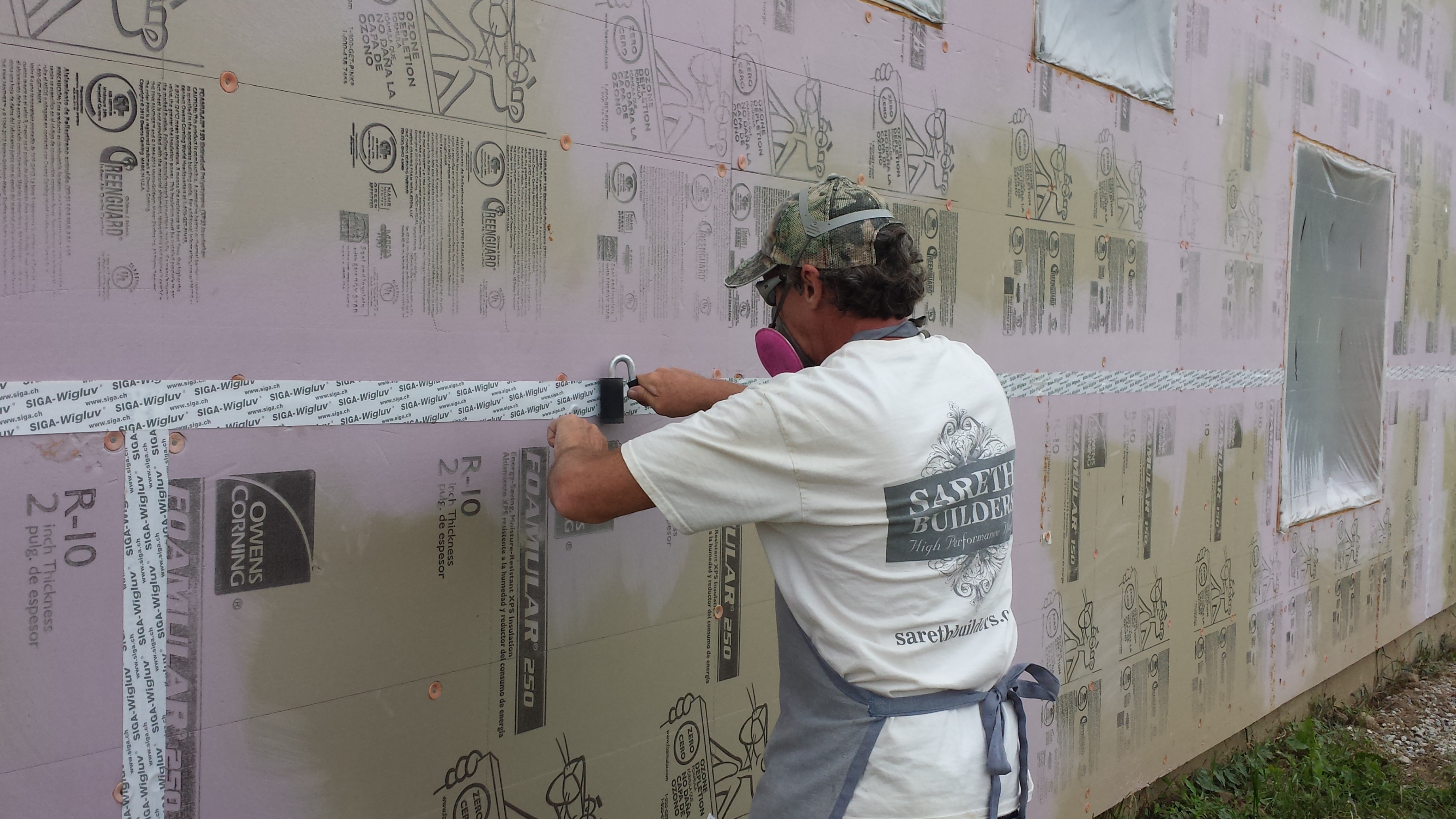
- Install rigid insulation and tape the joints, even if the water control membrane is behind the insulation. This is not for water management but to maintain a continuous thickness of stucco. Maintaining continuity in the stucco across joints avoids differential rates of drying between the thicker stucco at untaped joints and the thinner stucco over the field of the insulation. When the joints are left untapped, shadow lines can appear at the joints from this differential drying. For the same reason, the material used to tape the joints should roughly match the absorption of the insulation. Acrylic sheathing tape or self-adhered membrane is appropriate for XPS, while mesh tape is typically used with EPS insulations. After the above preparation, the installer may then:
- Install lath and stucco in accordance with the manufacturer’s instructions.
Ensuring Success
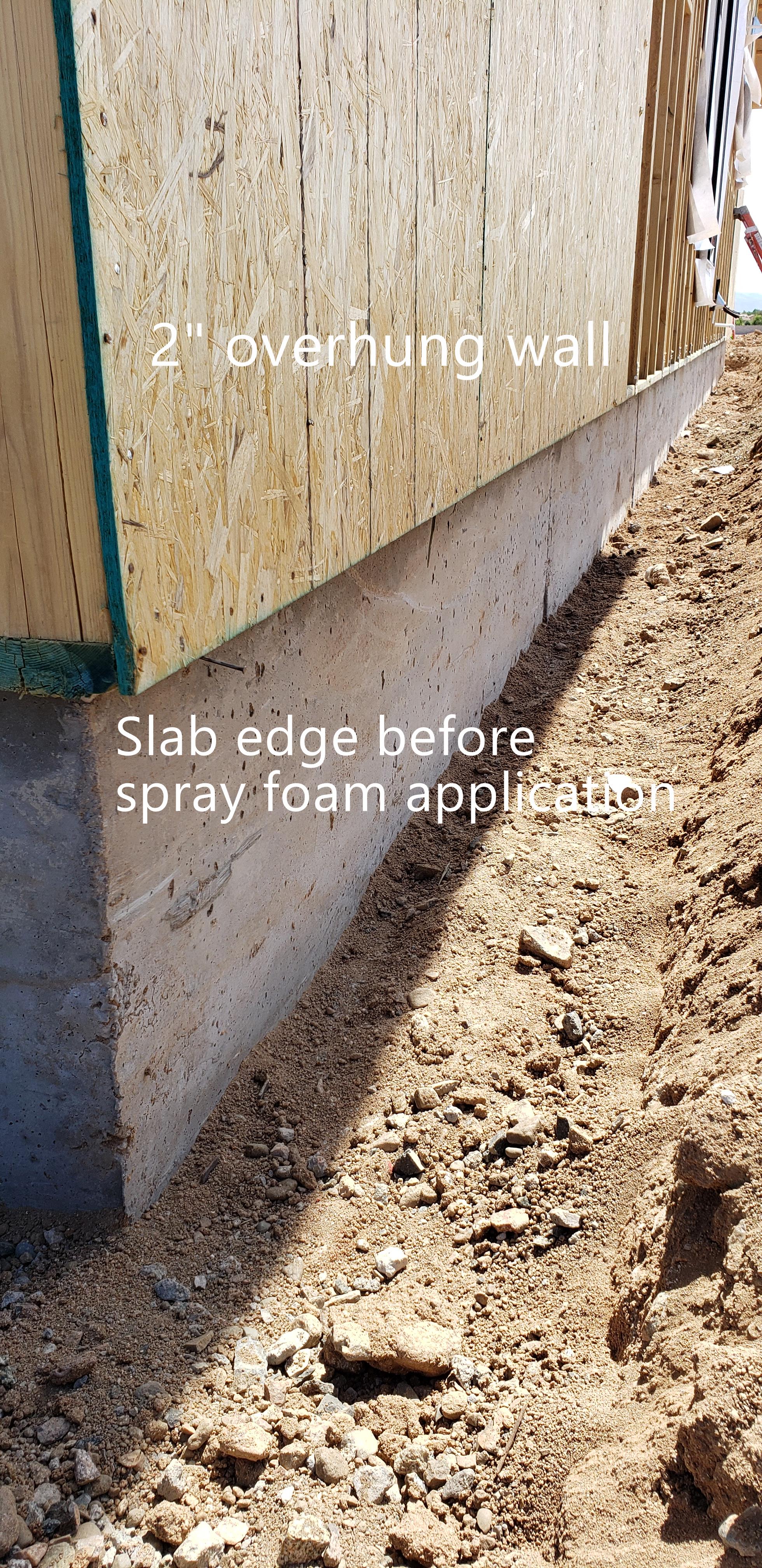
Ensure that all windows, doors, and penetrations are flashed and sealed to the water control membrane, not just to the face of the stucco. Install metal or rigid plastic through-wall flashing at the base of the wall and strip it in with self-adhered membrane so that water running down the drainage plane is directed to the exterior at the base of the wall. Wherever possible, use flanged electrical boxes and flanged penetrations for better integration with the building’s water control layer.
Tape the joints of the insulation, even when the water control layer and drainage plane are located behind the insulation, to keep stucco out of the joints so that a uniform stucco thickness is maintained for even drying.
Region
The location of the building will inform (1) the amount of drainage provided and (2) the amount of insulation in the assembly. If the climate receives more than 20 inches of rain annually, a drainage mat at least ¼ inch thick should be installed over the water control layer.
For insulation thicknesses, consult the International Energy Conservation Code (IECC) and the local building code. See the Compliance tab for more.
Training
Right and Wrong Images
Source
Source
Source
Source
Source
Compliance
Retrofit
SCOPE
To retrofit an existing stucco wall:
- Remove existing stucco.
- Evaluate the sheathing and water control layer for damage.
- Assess and repair causes of damage.
- Flash windows, doors, and other penetrations to new water control layer,
- Integrate new water control layer with existing walls assemblies.
See the U.S. Department of Energy Standard Work Specifications for more on adding exterior wall continuous insulation.
For more on working with walls, see the Pre-Retrofit Assessment of Walls, Windows, and Doors in the Building America Solution Center.
DESCRIPTION
To retrofit a wall system with stucco over rigid foam insulation, the existing stucco cladding must first be removed. With the cladding off, the exterior sheathing and water control layer should be evaluated for damage before to proceeding. Prior to replacing damaged sheathing and replacing or repairing the existing water control layer, it is important to assess the cause of any damage observed. Poor window flashing details and unsealed penetrations, for example, may need to be addressed independently of the new cladding work (by re-installing or replacing windows and penetrations and flashing them to the water control layer). Damage due to a lack of drainage in the original wall assembly, however, can be addressed as part of the retrofit by providing a drainage membrane, mat, or spacers as described in the “Description” tab of the new home guide.
If the retrofit involves the installation of a new water control layer but the existing windows, doors, and other penetrations are to remain, they must be flashed to the new water control layer. To accomplish this, a portion of the existing water control membrane should be left intact around these penetrations after demolition. The existing material that remains should then be shingle lapped and integrated with the new water control membrane with a compatible tape.
If only a portion of a building is to be retrofitted, ensure that the water control membrane of the new wall assembly is properly integrated with the water control layer of the adjacent existing wall assembly. At vertical transitions a self-adhered tape or transition strip compatible with both membranes can be used. At horizontal joints (likely at a floor level) a metal through-wall flashing is recommended (in lieu of simply shingle lapping and taping the water control layer above to the water control layer below). A through-wall flashing is especially important if the capacity of the lower wall assembly to drain water is poor or is unknown.
Follow the instructions in the Description tab of the new home guide for information on proceeding with the installation.
COMPLIANCE
See Compliance tab.
More Info
Case Studies
References and Resources
*For non-dated media, such as websites, the date listed is the date accessed.
Contributors to this Guide
The following authors and organizations contributed to the content in this Guide.
Sales
Reduced Thermal Bridging = Continuous Thermal Blanket Construction
Technical Description
Even when insulated, homes can still have unnecessary heat loss due to the ability of heat to transfer through the wood framing. Because framing can comprise up to one-fourth of the wall in stud-framed walls, the studs can significantly contribute to heat loss. To address this, a continuous thermal blanket of rigid foam can be installed on the exterior side of the walls, either over the plywood or OSB sheathing or in place of the wood sheathing. In attics, attic insulation can be installed to a depth that will cover the tops of the ceiling joists. Basements or crawlspaces can be sealed and insulated along the walls so that the floor joists are completely in conditioned space.
Questions? Comments? Contact our webmaster.