
Spray Foam Insulation Applied over the Siding of Existing Exterior Walls

    Scope
    Scope Images
    Image
    Spray foam is installed between new studs over the existing siding in this deep energy retrofit
    Scope

    Install spray foam on the exterior of the existing home after framing over the existing siding. Then install new siding over the new studs and spray foam for this deep energy retrofit technique.

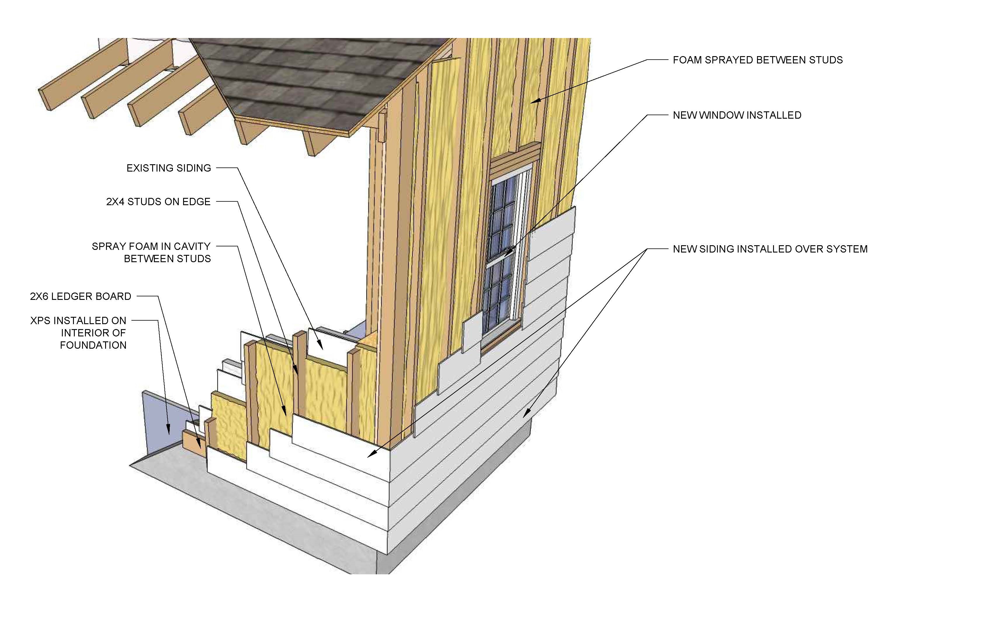
    In this design, add exterior spray foam insulation with stand-off furring. The design includes a 2x6 ledger board at the bottom and top of the wall, as well as 2x4 studs that are installed on edge to provide wall cavities that can hold a 3 inch layer of spray foam applied to the exterior face of the existing wall. New windows are installed, as well as new siding on top of the insulation. In addition, extruded polystyrene (XPS) is installed in the interior of the foundation walls and spray foam insulation is added to the attic space.

    This retrofit measure requires a crew that can perform a number of different tasks (e.g., framing, flashing, window install, trim carpentry). Because of the project sequencing, this project does not lend itself to piecemeal subcontracting various tasks (e.g., framing subcontractor, window installer, drainage plane installer, trim carpenter).

    See the Compliance Tab for related codes and standards requirements, and criteria to meet national programs such as DOE’s Zero Energy Ready Home programENERGY STAR Single-Family New Homes, and Indoor airPLUS.

    Description
    Description

    One method to significantly increase the insulation level of an existing home without sacrificing interior space is to install spray foam insulation on the exterior of the home. This measure involves installing 2x4 studs over the existing siding. The 2x4s are held slightly away from the wall with metal clips so that when the spray is applied to fill the new 2x4 wall cavities, it can fill in between the 2x4s and the existing walls (see Figure 1). The advantages of this strategy include using spray foam to encapsulate existing siding materials that might include lead paint, reducing the thermal bridging or transfer of heat through the existing wall studs, and creating a vented rain screen assembly to promote drying.

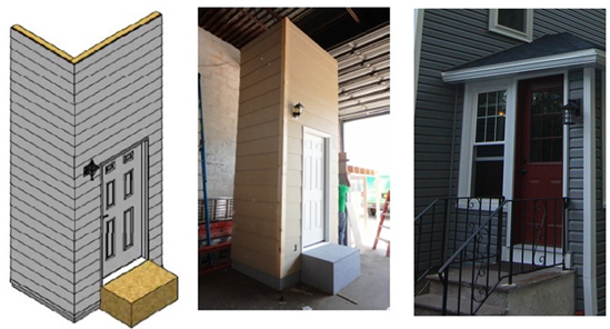
    This strategy might be considered by homeowners who are already considering replacing siding or windows or who are conducting some other exterior upgrade.

    Deep energy retrofit showing insulation sprayed on exterior of walls over existing siding.
    Figure 1. Deep energy retrofit showing insulation sprayed on exterior of walls over existing siding. (Source: IBACOS.)


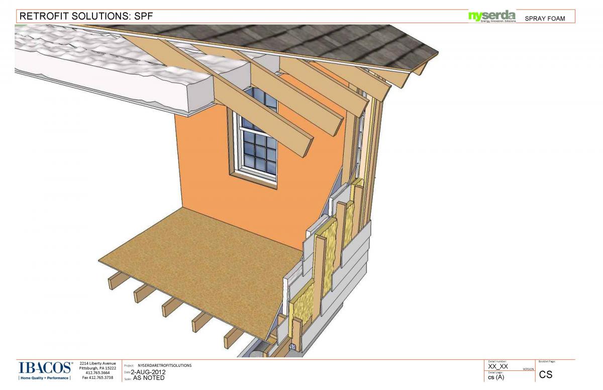
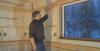
    In a field study conducted by IBACOS in New York (see Figure 2), the exterior spray foam strategy was designed, implemented in a test facility to determine techniques for working around wall penetrations like wiring and doors, then installed on site in an actual home. Results from the field study (Herk and Poerschke 2015) found this strategy achieved the following energy-related targets:

    • Whole-house air leakage improvements that can approach or be lower than 0.25 CFM 50/shell square foot (SSF) upon completion.
    • Center of wall R-value of approximately R-25.
    • An exterior wall insulation retrofit strategy that can be accomplished for approximately $12 to $18 per SSF. This includes the installation of new wall framing and the removal/installation of windows, window trim, insulation, and bug screen. Siding was a cost that is not included in this number.

    Although it is likely that this retrofit technique can be applied to most siding types, at this time, research has not been done to determine the suitability of the application on brick or stone siding.

    Retrofit spray foam over existing walls showing design, testing, and final construction.
    Figure 2. Retrofit spray foam over existing walls showing design, testing, and final construction. (Source: IBACOS.)


    How to Install Spray Foam Insulation on Existing Walls

    1. Assess the existing condition of the wall. (See Figure 3.) Be sure to look for and make note of loose or crooked siding. These types of siding imperfections could lead to an uneven ledger board or stud, which then could result in a wavy siding application.
      Assess the existing condition of the wall.
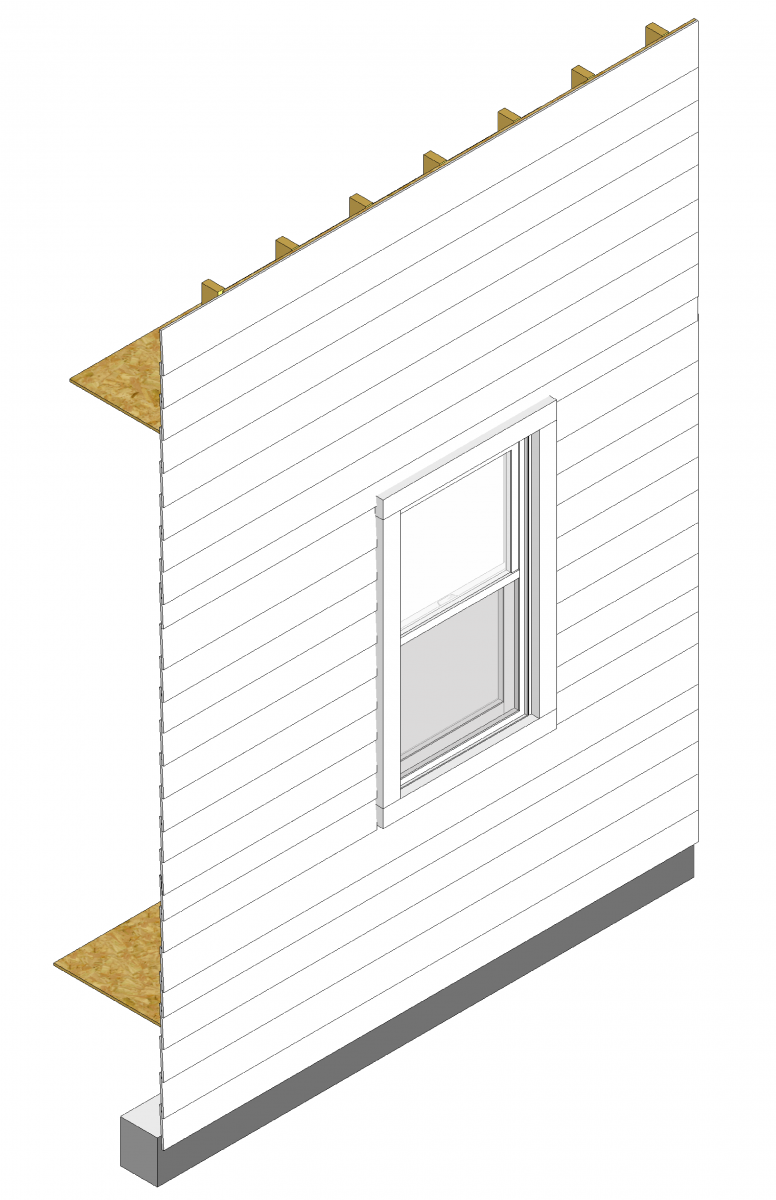
      Figure 3. Assess the existing condition of the wall. (Source: IBACOS.)
    2. Remove the existing window trim and fasten the ledger boards through the existing exterior cladding and sheathing. (See Figure 4.) If the existing wall surface is uneven, shim the ledger boards if necessary to keep the new framing and any doors and windows that will be installed a uniform distance from the existing wall.
      Remove the existing window trim and fasten the ledger boards through the existing exterior cladding and sheathing.
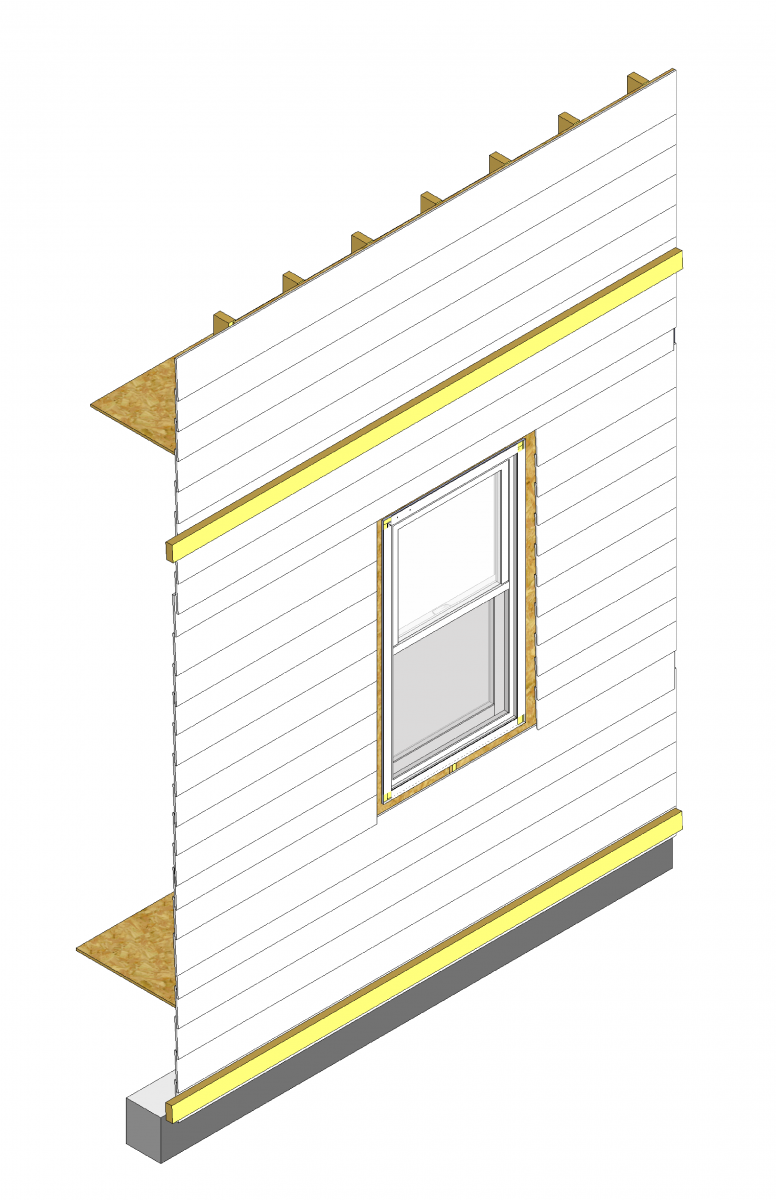
      Figure 4. Remove the existing window trim and fasten the ledger boards through the existing exterior cladding and sheathing. (Source: IBACOS.)
    3. Attach metal “L” clips on the top and bottom ledger board—one on either side of where a new vertical 2x4 will be attached. (See Figure 5.) Remove the existing window and install new framing for the new window.
      Attach metal “L” clips on the top and bottom ledger board for new vertical 2x4s.
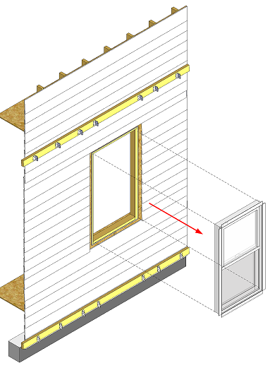
      Figure 5. Attach metal “L” clips on the top and bottom ledger board for new vertical 2x4s. (Source: IBACOS.)
    4. Install the vertical 2x4s, spaced as needed based on structural calculations and siding manufacturer requirements. These are attached to the ledger boards using the metal “L” clips and they create a framework to hold the spray foam. (See Figures 6 and 7.)
      Install the vertical 2x4s, spaced as needed based on structural calculations and siding manufacturer requirements.
      Figure 6. Install the vertical 2x4s, spaced as needed based on structural calculations and siding manufacturer requirements. (Source: IBACOS.)
      Ledger board, metal brackets, and vertical 2x4s have been installed in preparation for exterior spray foam in this retrofit exterior wall insulation technique.
      Figure 7. Ledger board, metal brackets, and vertical 2x4s have been installed in preparation for exterior spray foam in this retrofit exterior wall insulation technique. (Source: IBACOS.)
    5. Install two horizontal framing members on the top and bottom of the rough opening for the new window. Slightly slope the sill framing to the exterior. (See Figure 8.)
      Install two horizontal framing members on the top and bottom of the rough opening for the new window.
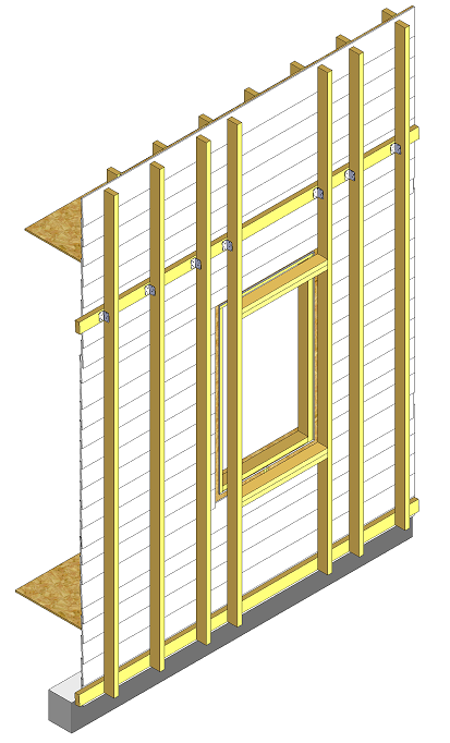
      Figure 8. Install two horizontal framing members on the top and bottom of the rough opening for the new window. Slightly slope the sill framing to the exterior. (Source: IBACOS.)
    6. Install the sill pan in the window frame. (See Figure 9.)
      Install the sill pan in the window frame.
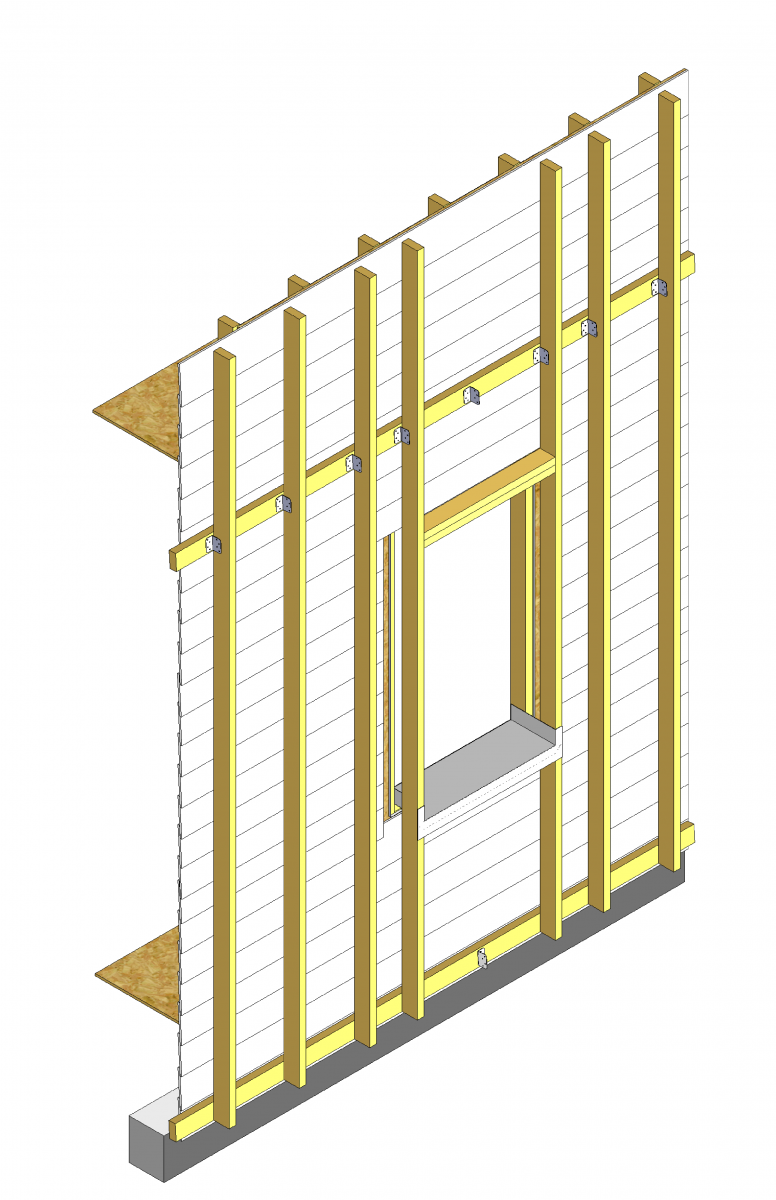
      Figure 9. Install the sill pan in the window frame. (Source: IBACOS.)
    7. Install flexible flashing over the sill pan and at least 6 inches up the sides of the jamb. (See Figure 10.)
      Install the flexible flashing over the sill pan and at least 6 inches up the sides of the jamb.
      Figure 10. Install the flexible flashing over the sill pan and at least 6 inches up the sides of the jamb. (Source: IBACOS.)
    8. Install caulk on the face of the rough opening at the jambs and head. Do not caulk the sill. (See Figure 11.)
      Install caulk on the face of the rough opening at the jambs and head. Do not caulk the sill.
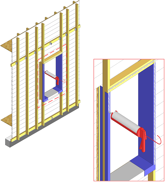
      Figure 11. Install caulk on the face of the rough opening at the jambs and head. Do not caulk the sill. (Source: IBACOS.)
    9. Install the new window or re-install the old window. (See Figures 12 and 13.)
      Install the new window.
      Figure 12. Install the new window. (Source: IBACOS.)
      Windows are installed in new framing in preparation for adding exterior spray foam insulation.
      Figure 13. Windows are installed in new framing in preparation for adding exterior spray foam insulation. (Source: IBACOS.)
    10. Install the jamb flashing (flat on the face of the window flange). (See Figure 14.)
      Install the jamb flashing (flat on the face of the window flange).
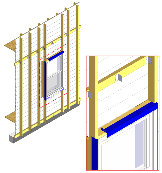
      Figure 14. Install the jamb flashing (flat on the face of the window flange). (Source: IBACOS.)
    11. Install the head flashing from the face of the existing wall to lap over the head of the new window. Also, tape the flashing at the head using straight flashing tape lapped over the horizontal part of the head framing. (See Figure 15.)
      Install head flashing from the face of the existing wall to lap over the head of the new window.
      Figure 15. Install head flashing from the face of the existing wall to lap over the head of the new window. (Source: IBACOS.)
    12. Install the vertical framing members above and below the new window, and install the insect screen to the bottom of the new wall. Air seal the window from the interior using non-expanding foam sealant and install internal jamb extensions to prevent exterior spray foam from getting into the house. (See Figures 16 and 17.) Cover the windows and exposed foundation with plastic to minimize the possibility of damage due to overspraying with the spray foam.
      Install the vertical framing members above and below the new window, and install the insect screen to the bottom of the new wall.
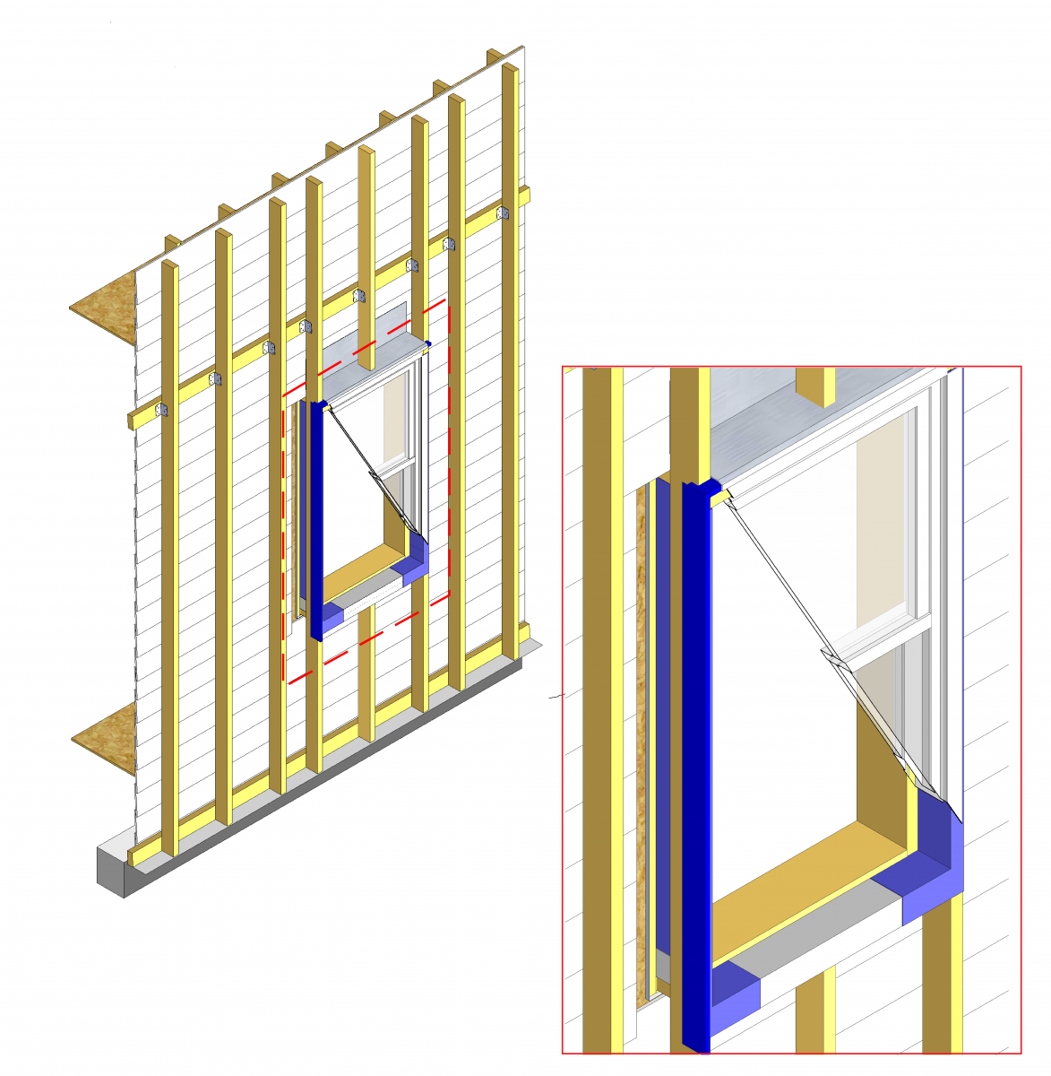
      Figure 16. Install the vertical framing members above and below the new window, and install the insect screen to the bottom of the new wall. (Source: IBACOS.)
      First spray foam along the inside edges of each vertical 2x4 to “picture frame” the area.
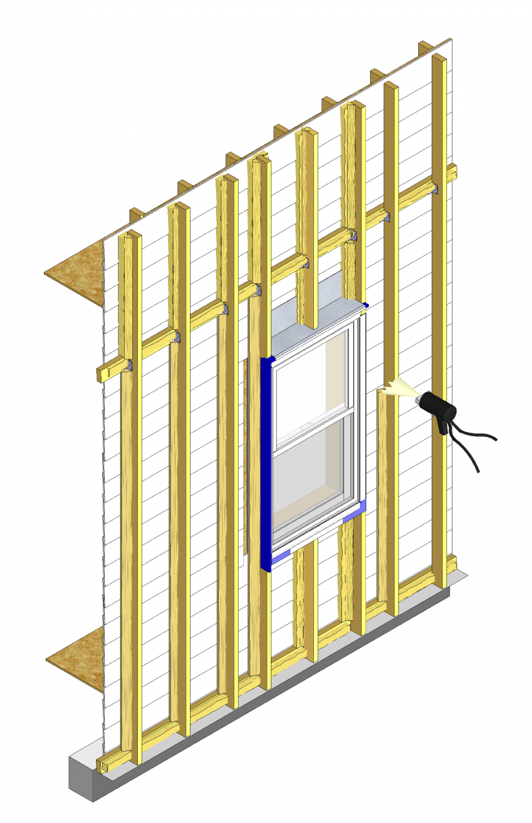
      Figure 17. First spray foam along the inside edges of each vertical 2x4 to “picture frame” the area. (Source: IBACOS.)
    13. Spray insulation within the cavities of the new wall. (See Figure 18.)
      Spray insulation within the cavities of the new wall.
      Figure 18. Spray insulation within the cavities of the new wall. (Source: IBACOS.)
    14. Install the new cladding and install the new window trim. (See Figure 19.)
      Install the new cladding and install the new window trim.
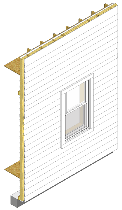
      Figure 19. Install the new cladding and install the new window trim. (Source: IBACOS.)


    Success
    Ensuring Success
    • Cover the windows and exposed foundation with plastic to protect against foam overspray.
    • Use extra metal clips or picture frame spraying technique to keep studs in place while installing spray foam in new stud cavities.
    • For efficiency, hire one contractor or crew that can perform most or all of the tasks involved in this retrofit measure (e.g., framing, flashing, window install, trim carpentry).
    Climate
    Climate

    No climate specific information applies.

    Training
    Presentations
    Videos
    Compliance

    Compliance

    The Compliance tab contains both program and code information. Code language is excerpted and summarized below. For exact code language, refer to the applicable code, which may require purchase from the publisher. While we continually update our database, links may have changed since posting. Please contact our webmaster if you find broken links.


    ENERGY STAR Single-Family New Homes, Version 3/3.1 (Rev. 11)

    ENERGY STAR Certified Homes requires that ceiling, wall, floor, and slab insulation levels meet or exceed those specified in the 2009 International Energy Conservation Code (IECC) with some alternatives and exceptions, and achieve Grade 1 installation per RESNET Standards (see 2009 and 2012 IECC Code Level Insulation – ENERGY STAR Requirements and Insulation Installation (RESNET Grade 1). If the state or local residential building energy code requires higher insulation levels than those specified in the 2009 IECC, you must meet or exceed the locally mandated requirements. Some states have adopted the 2012 or 2015 IECC. Visit the U.S. DOE Building Energy Codes Program to see what code has been adopted in each state.

    National Rater Design Review Checklist

    3. High-Performance Insulation.
    3.1 Specified ceiling, wall, floor, and slab insulation levels comply with one of the following options:
    3.1.1 Meets or exceeds 2009 IECC levels5, 6, 7 OR;
    3.1.2 Achieves ≤ 133% of the total UA resulting from the U-factors in 2009 IECC Table 402.1.3, per guidance in Footnote 5d, AND specified home infiltration does not exceed the following:6, 7

    • 3 ACH50 in CZs 1, 2
    • 2.5 ACH50 in CZs 3, 4
    • 2 ACH50 in CZs 5, 6, 7
    • 1.5 ACH50 in CZ 8

    Footnote 5) Specified levels shall meet or exceed the component insulation levels in 2009 IECC Table 402.1.1. The following exceptions apply:
    a. Steel-frame ceilings, walls, and floors shall meet the insulation levels of 2009 IECC Table 402.2.5. In CZ 1 and 2, the continuous insulation requirements in this table shall be permitted to be reduced to R-3 for steel-frame wall assemblies with studs spaced at 24 in. on center. This exception shall not apply if the alternative calculations in d) are used;
    b. For ceilings with attic spaces, R-30 shall satisfy the requirement for R-38 and R-38 shall satisfy the requirement for R-49 wherever the full height of uncompressed insulation at the lower R-value extends over the wall top plate at the eaves. This exemption shall not apply if the alternative calculations in d) are used;
    c. For ceilings without attic spaces, R-30 shall satisfy the requirement for any required value above R-30 if the design of the roof / ceiling assembly does not provide sufficient space for the required insulation value. This exemption shall be limited to 500 sq. ft. or 20% of the total insulated ceiling area, whichever is less. This exemption shall not apply if the alternative calculations in d) are used;
    d. An alternative equivalent U-factor or total UA calculation may also be used to demonstrate compliance, as follows: An assembly with a U-factor equal or less than specified in 2009 IECC Table 402.1.3 complies. A total building thermal envelope UA that is less than or equal to the total UA resulting from the U-factors in Table 402.1.3 also complies. The performance of all components (i.e., ceilings, walls, floors, slabs, and fenestration) can be traded off using the UA approach. Note that Items 3.1 through 3.3 of the National Rater Field Checklist shall be met regardless of the UA tradeoffs calculated. The UA calculation shall be done using a method consistent with the ASHRAE Handbook of Fundamentals and shall include the thermal bridging effects of framing materials. The calculation for a steel-frame envelope assembly shall use the ASHRAE zone method or a method providing equivalent results, and not a series-parallel path calculation method.

    Footnote 6) Consistent with the 2009 IECC, slab edge insulation is only required for slab-on-grade floors with a floor surface less than 12 inches below grade. Slab insulation shall extend to the top of the slab to provide a complete thermal break. If the top edge of the insulation is installed between the exterior wall and the edge of the interior slab, it shall be permitted to be cut at a 45-degree angle away from the exterior wall. Alternatively, the thermal break is permitted to be created using ≥ R-3 rigid insulation on top of an existing slab (e.g., in a home undergoing a gut rehabilitation). In such cases, up to 10% of the slab surface is permitted to not be insulated (e.g., for sleepers, for sill plates). Insulation installed on top of slab shall be covered by a durable floor surface (e.g., hardwood, tile, carpet).

    Footnote 7) Where an insulated wall separates a garage, patio, porch, or other unconditioned space from the conditioned space of the house, slab insulation shall also be installed at this interface to provide a thermal break between the conditioned and unconditioned slab. Where specific details cannot meet this requirement, partners shall provide the detail to EPA to request an exemption prior to the home’s certification. EPA will compile exempted details and work with industry to develop feasible details for use in future revisions to the program. A list of currently exempted details is available at: energystar.gov/slabedge.

    National Rater Field Checklist

    Thermal Enclosure System.
    1. High-Performance Fenestration & Insulation.
    1.3 All insulation achieves Grade I install. per ANSI / RESNET / ICC Std. 301. Alternatives in Footnote 5.5, 6

    Footnote 5) Two alternatives are provided: a) Grade II cavity insulation is permitted to be used for assemblies that contain a layer of continuous, air impermeable insulation ≥ R-3 in Climate Zones 1 to 4, ≥ R-5 in Climate Zones 5 to 8; b) Grade II batts are permitted to be used in floors if they fill the full width and depth of the floor cavity, even when compression occurs due to excess insulation, as long as the R-value of the batts has been appropriately assessed based on manufacturer guidance and the only defect preventing the insulation from achieving Grade I is the compression caused by the excess insulation.

    Footnote 6) Ensure compliance with this requirement using ANSI / RESNET / ICC Std. 301 including all Addenda and Normative Appendices, with new versions and Addenda implemented according to the schedule defined by the HCO that the home is being certified under, with approved exceptions listed at www.energystar.gov/ERIExceptions.

    2. Fully-Aligned Air Barriers 7 - At each insulated location below, a complete air barrier is provided that is fully aligned as follows:
    Ceilings: At interior or exterior horizontal surface of ceiling insulation in Climate Zones 1-3; at interior horizontal surface of ceiling insulation in Climate Zones 4-8. Also, at exterior vertical surface of ceiling insulation in all climate zones (e.g., using a wind baffle that extends to the full height of the insulation in every bay or a tabbed baffle in each bay with a soffit vent that prevents wind washing in adjacent bays). 8
    Walls: At exterior vertical surface of wall insulation in all climate zones; also at interior vertical surface of wall insulation in Climate Zones 4-8.9
    Floors: At exterior vertical surface of floor insulation in all climate zones and, if over unconditioned space, also at interior horizontal surface including supports to ensure alignment. Alternatives in Footnotes 12 & 13.11, 12, 13
    2.6 Floors above garages, floors above unconditioned basements or crawlspaces, and cantilevered floors.
    2.7 All other floors adjoining unconditioned space (e.g., rim / band joists at exterior wall or at porch roof).

    Footnote 7) For purposes of this Checklist, an air barrier is defined as any durable solid material that blocks air flow between conditioned space and unconditioned space, including necessary sealing to block excessive air flow at edges and seams and adequate support to resist positive and negative pressures without displacement or damage. EPA recommends, but does not require, rigid air barriers. Open-cell or closed-cell foam shall have a finished thickness ≥ 5.5 in. or 1.5 in., respectively, to qualify as an air barrier unless the manufacturer indicates otherwise. If flexible air barriers such as house wrap are used, they shall be fully sealed at all seams and edges and supported using fasteners with caps or heads ≥ 1 in. diameter unless otherwise indicated by the manufacturer. Flexible air barriers shall not be made of kraft paper, paper-based products, or other materials that are easily torn. If polyethylene is used, its thickness shall be ≥ 6 mil.

    Footnote 8) All insulated ceiling surfaces, regardless of slope (e.g., cathedral ceilings, tray ceilings, conditioned attic roof decks, flat ceilings, sloped ceilings), must meet the requirements for ceilings.

    Footnote 9) All insulated vertical surfaces are considered walls (e.g., above and below grade exterior walls, knee walls) and must meet the air barrier requirements for walls. The following exceptions apply: air barriers recommended, but not required, in adiabatic walls in multifamily dwellings; and, in Climate Zones 4 through 8, an air barrier at the interior vertical surface of insulation is recommended but not required in basement walls or crawlspace walls. For the purpose of these exceptions, a basement or crawlspace is a space for which ≥ 40% of the total gross wall area is below-grade.

    Footnote 11) EPA highly recommends, but does not require, an air barrier at the interior vertical surface of floor insulation in Climate Zones 4-8.

    Footnote 12) Examples of supports necessary for permanent contact include staves for batt insulation or netting for blown-in insulation. Alternatively, supports are not required if batts fill the full depth of the floor cavity, even when compression occurs due to excess insulation, as long as the R-value of the batts has been appropriately assessed based on manufacturer guidance and the only defect preventing the insulation from achieving the required installation grade is the compression caused by the excess insulation.

    Footnote 13) Alternatively, an air barrier is permitted to be installed at the exterior horizontal surface of the floor insulation if the insulation is installed in contact with this air barrier, the exterior vertical surfaces of the floor cavity are also insulated, and air barriers are included at the exterior vertical surfaces of this insulation.

    Please see the ENERGY STAR Single-Family New Homes Implementation Timeline for the program version and revision currently applicable in your state.


    DOE Zero Energy Ready Home (Revision 07)

    The DOE Zero Energy Ready Home Program is a voluntary high-performance home labeling program for new homes operated by the U.S. Department of Energy. Builders and remodelers who are conducting retrofits are welcome to seek certification for existing homes through this voluntary program.

    Exhibit 1 Mandatory Requirements.
    Exhibit 1, Item 1) Certified under the ENERGY STAR Qualified Homes Program or the ENERGY STAR Multifamily New Construction Program.
    Exhibit 2, Item 2) Ceiling, wall, floor, and slab insulation shall meet or exceed 2015 IECC levels and achieve Grade 1 installation, per RESNET standards.


    2009-2021 IECC and IRC Insulation Requirements Table

    The minimum insulation requirements for ceilings, walls, floors, and foundations in new homes, as listed in the 2009, 2012, 2015, 2018, and 2021 IECC and IRC, can be found in this table


    2009 International Energy Conservation Code (IECC)

    Section 402.4 Air leakage (Mandatory).
    Section 402.4.1 Building Thermal Envelope.
    Section 402.4.2 Air sealing and insulation.
    Table 402.4.2 Air Barrier and Insulation Inspection Component Criteria

    2012, 2015, 2018, and 2021 IECC

    Section R402.4 Air leakage (Mandatory).
    Section R402.4.1 Building Thermal Envelope.
    Table R402.4.1.1 Air Barrier and Insulation Installation

    Retrofit:  2009, 2012, 2015, 2018,  and 2021 IECC

    Section R101.4.3 (in 2009 and 2012). Additions, alterations, renovations, or repairs shall conform to the provisions of this code, without requiring the unaltered portions of the existing building to comply with this code. (See code for additional requirements and exceptions.)

    Chapter 5 (in 2015, 2018, 2021). The provisions of this chapter shall control the alteration, repair, addition, and change of occupancy of existing buildings and structures.


    2009 International Residential Code (IRC)

    Section R302.5 Dwelling/garage opening/penetration protection.
    Section R302.6 Dwelling/garage fire separation.
    Table R302.6 Dwelling/Garage Separation.
    Section R315.2 Where required in existing dwellings.
    Section N1102.4 Air leakage (Mandatory).
    Section N1102.4.1 Building Thermal Envelope.
    Section N1102.4.2 Air sealing and insulation.
    Table N1102.4.2 Air Barrier and Insulation Inspection Component Criteria

    2012, 2015, 2018, and 2021 IRC

    Section R302.5 Dwelling/garage opening/penetration protection.
    Section R302.6 Dwelling/garage fire separation.
    Table R302.6 Dwelling/Garage Separation.
    Section R315.3 Where required in existing dwellings.
    Section N1102.4 Air leakage (Mandatory).
    Section N1102.4.1 Building Thermal Envelope.
    Table N1102.4.1.1 Air Barrier and Insulation Installation

    Retrofit:  2009, 2012, 2015, 2018,  and 2021 IRC

    Section R102.7.1 Additions, alterations, or repairs. Additions, alterations, renovations, or repairs shall conform to the provisions of this code, without requiring the unaltered portions of the existing building to comply with the requirements of this code, unless otherwise stated. (See code for additional requirements and exceptions.)

    Appendix J regulates the repair, renovation, alteration, and reconstruction of existing buildings and is intended to encourage their continued safe use.

    More

    More Info.

    Access to some references may require purchase from the publisher. While we continually update our database, links may have changed since posting. Please contact our webmaster if you find broken links.

    Case Studies
    Author(s)
    IBACOS
    Organization(s)
    IBACOS
    Publication Date
    Description
    Case study describing a stand-off furring strategy that minimizes the physical connections to each existing wall stud, uses spray foam to encapsulate existing siding materials (including lead paint), and creates a vented rain screen assembly to promote drying.
    References and Resources*
    Author(s)
    Burdick Arlan
    Organization(s)
    IBACOS
    Publication Date
    Description
    Report outlining the issues with using existing ducts with a new low-load HVAC system, which reduces throw at supply registers causing decreased mixing of supply and room air, leading to potential thermal comfort complaints.
    Author(s)
    Joint Center for Housing Studies of Harvard University
    Organization(s)
    Joint Center for Housing Studies of Harvard University
    Publication Date
    Description
    Even as the worst housing market correction in more than 60 years appeared to turn a corner in 2009, the fallout from sharply lower home prices and high unemployment continued.
    Author(s)
    Herk,
    Poerschke
    Organization(s)
    IBACOS
    Publication Date
    Description
    The New York State Energy Research and Development Authority (NYSERDA) is interested in finding cost-effective solutions for deep energy retrofits (DERs) related to exterior wall insulation in a cold climate, with targets of 50% peak load reduction and 50% space conditioning energy savings.
    Author(s)
    Air Conditioning Contractors of America
    Organization(s)
    ACCA
    Publication Date
    Description
    Standard covering equipment sizing loads for single-family-detached homes, small multi-unit structures, condo­miniums, town houses and manufactured homes.
    Author(s)
    Air Conditioning Contractors of America
    Organization(s)
    ACCA
    Publication Date
    Description
    Standard outlining industry procedure for sizing residential duct systems.
    Author(s)
    Rutkowski
    Organization(s)
    Air Conditioning Contractors of America
    Publication Date
    Description
    The manual covers residential zoning issues - multiple, single-zone, and central multi-zone systems - and includes advice on working with homeowners to adapt the heating or cooling system design to meet modern home design features.
    Author(s)
    American Society of Heating Refrigeration and Air-Conditioning Engineers
    Organization(s)
    ASHRAE,
    American National Standards Institute,
    ANSI
    Publication Date
    Description
    Standard 55 specifies conditions for acceptable thermal environments and is intended for use in design, operation, and commissioning of buildings and other occupied spaces. This is the current version of the standard, which was published in the year 2021, and is available for preview and purchase at...
    *For non-dated media, such as websites, the date listed is the date accessed.
    Contributors to this Guide

    The following authors and organizations contributed to the content in this Guide.

    Last Updated

    Mobile Field Kit

    The Building America Field Kit allows you to save items to your profile for review or use on-site.

    Sign Up  or  Log In

    Did you find this information helpful?

    If you have questions and/or would like a reply to this feedback, please include your e-mail address in the message.
    This question is for testing whether or not you are a human visitor and to prevent automated spam submissions.