

Scope
Assess property or building to determine feasibility for solar-thermal (water heating) and, or, solar electric (photovoltaic (PV)) technologies. A solar assessment is also needed for structures intended to use passive solar heating and cooling features.
If solar resources are adequate, the solar assessor shall designate the location of future/proposed PV arrays and solar thermal panels. Assessors should work with owners, builders and designers to detail the location and the square footage of the proposed solar array or panels on site plans for a single home or for a multi-home development. If the array or panels will be located on a roof, the assessor shall indicate the location of the equipment on a roof plan. If the roof is not a feasible location, panels and arrays may be mounted on other structures (such as garages, carports, or sheds) or ground-mounted racks. The solar assessor shall identify the orientation (azimuth) of the proposed array location and show the orientation on the site and roof plans. The assessor shall also measure the amount of shading on the proposed array area.
The North American Board of Certified Energy Practitioners (NABCEP) provides voluntary certifications for solar site assessment personnel that include provisions for site analysis.
See the Compliance Tab for links to related codes and standards and voluntary federal energy-efficiency program requirements.
Description
At its core, a solar assessment is a prediction of available solar resources, often coupled with an economic analysis. This guide focuses on the resource assessment.
A general assessment of the availability of solar energy in different locations can be determined using the internet tools listed below.
- DOE’s PVWatts® Calculator estimates the energy production and cost of energy of grid-connected photovoltaic energy systems throughout the world. It allows homeowners, small building owners, installers and manufacturers to easily develop estimates of the performance of potential PV installations.
- The RETScreen® International Solar Water Heating Model can be used world-wide to evaluate the energy production, life-cycle costs, and greenhouse gas emissions reduction for three applications: domestic hot water, industrial process heat and swimming pools (indoor and outdoor), ranging in size from small residential systems to large-scale commercial, institutional and industrial systems. The model contains a database of essentially all commercially available solar thermal collectors. The model is free, but registration is required. This site also includes models for evaluating PV systems and other renewable and energy-efficient technologies.
Orientation and Inclination
Two important concepts for a site assessment are the orientation toward due south (azimuth) and the inclination or tilt (angle off of horizontal) of the arrays or panels. Orientation is typically expressed as the angle a solar device faces off of due south. For example, a PV array sitting on a house facing due south (corrected for magnetic declination) would have an azimuth of 180°. (South facing orientation = 180º, East = 90º, West = 270º.) The figures below illustrate these terms (Baechler et al 2007).
This table shows the conversion of example roof pitches into their approximate tilt in degrees. A number of conversion calculators are available on the web.
| Approximate Roof Pitch | Approximate Roof Tilt in Degrees |
|---|---|
| Flat | 0° |
| 2 in 12 | 9.5° |
| 4 in 12 | 18.4° |
| 6 in 12 | 26.5° |
| 12 in 12 | 45° |
| Vertical | 90° |
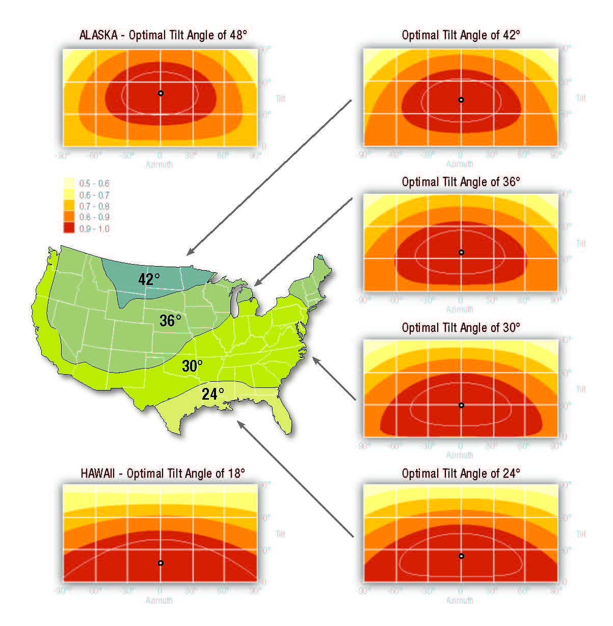
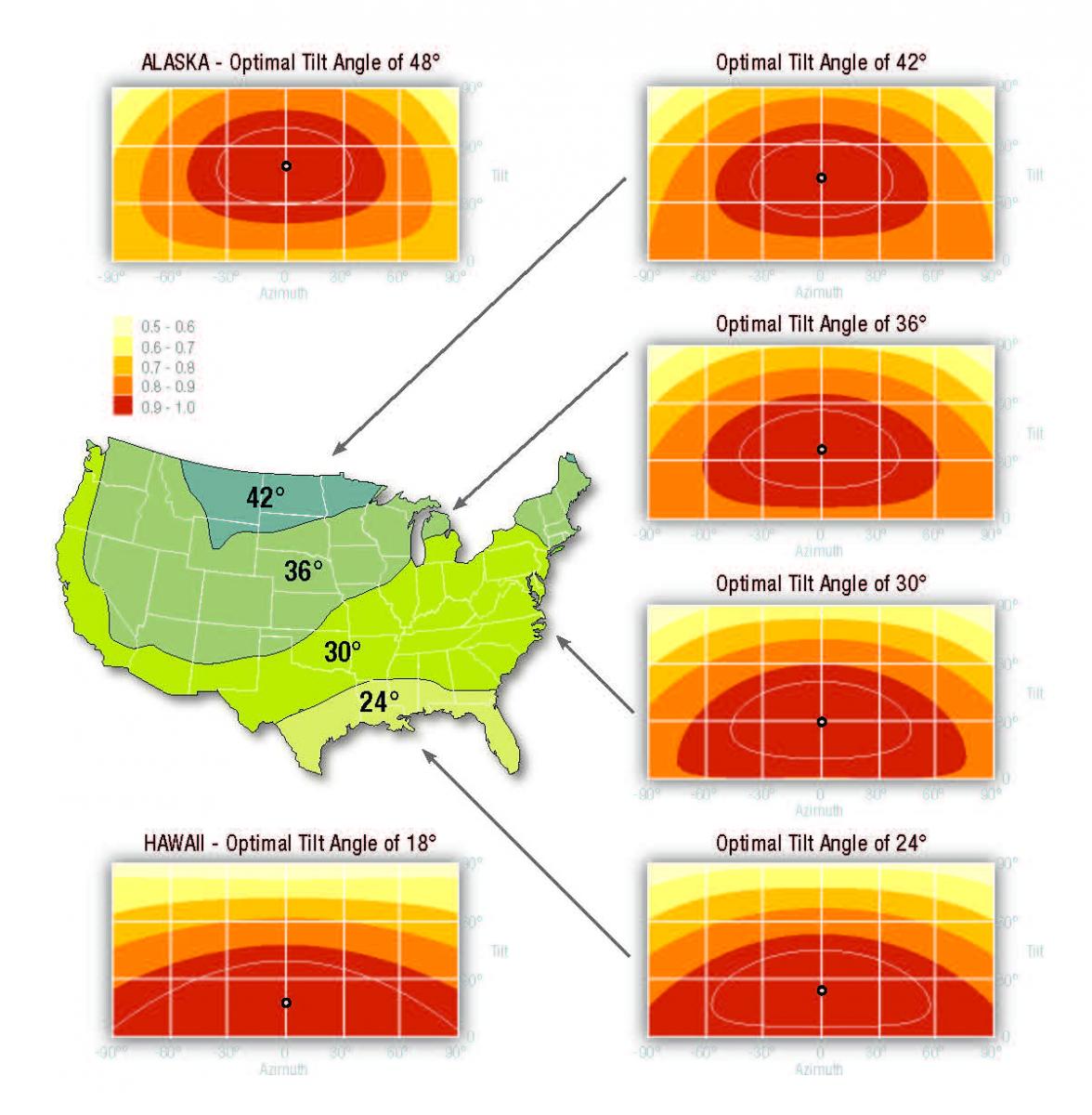
Solar orientation and inclination will influence how well a PV array or a solar panel performs. However, roof tilt (inclination) and southern orientation (azimuth) are quite flexible for the entire U.S. The figure below identifies optimal tilt angles for the shaded regions of the maps. The charts show the percentage of solar energy available in each of the regions as the tilt and azimuth change. For example in the portion of the country where the optimal tilt angle is 30° (most of the country), at an azimuth of 180° (due south) the tilt can run from flat (0°) all the way to 55° and still receive 90% to 100% of available energy, as shown by the colored bands in the chart. If the tilt is at the optimum of 30o the azimuth could vary by about 65° either east or west (115° to 245°) and still receive 90% to 100% of the available energy. The data for the following figure is taken from Christiansen and Barker 2001 and the figure was shown in Baechler et al 2007. The numbers shown at the bottom of each chart, above the word azimuth, are difference in degrees off of due south, for example, 90° indicates that the panels would be facing due East and -90° indicates the panels would face due west.
Existing Homes
For roof-mounted arrays on existing homes, the assessor shall work with the owner to determine the age of the roof covering. Roofing materials should have a minimum of 10-years life remaining before they must be replaced. New roofing material is highly recommended.
The solar assessor shall work with the owner, builder, and designer to determine the inclination (angle) for the proposed arrays and panels. For existing structures, the angle may be measured with an angle-finder, protractor, or smart-phone application. The inclination shall be shown on the roof or site plans.
The assessor shall determine the structure of the roof for array dead-load and wind up-lift capacity. Common rules-of-thumb specify a minimum of 2”x4” rafters spaced 24” on center, or engineered truss construction. Local building codes may also specify maximum rafter span distances. If these minimums are not met, a structural engineering study by a licensed professional engineer will likely be required.
The capacity of the electrical service shall also be ascertained for the potential addition of a PV system . This is commonly determined by the electrical current rating of the main service panel and/or main breaker. The current output of the proposed PV inverter may not exceed 20% of the main breaker rating. There must also be available capacity in the service panel for PV disconnects/breakers, typically two open spaces. If the electrical service is not compliant with current code standards, determine the scope of work required to make it compliant. See Article 690 of the National Electrical Code for more information.
Shading
A more specific on-site assessment includes an analysis of potential shading. The assessor’s objective is to predict for the entire year how chimneys, dormers, trees, antennas, and other obstructions might shade solar equipment. Several devices are available to assist with the site assessment. The following descriptions are adapted from Baechler et al (2007) and an article on the Home Power website by Justine Sanchez (issue date 2009, updated 2012). There are also several smart phone applications that can assist with shading assessment.
The Solar Pathfinder has been a common solar site analysis tool since the late 1970s. It uses a clear plastic dome over a sun-path diagram to show surrounding obstructions.
This device is first oriented and leveled, then users can take a digital photograph of the setup for use in the software program, or trace the superimposed reflections onto the black chart with a white pencil, which reveals which months and times of day objects may shade solar devices or windows.
Sun-path charts for different latitudes are available, and each chart includes solar data to show the percentage of sunlight available for each hour of each month. The Solar Pathfinder Assistant software is used with digital photos of Pathfinder readings to generate detailed shading analysis.
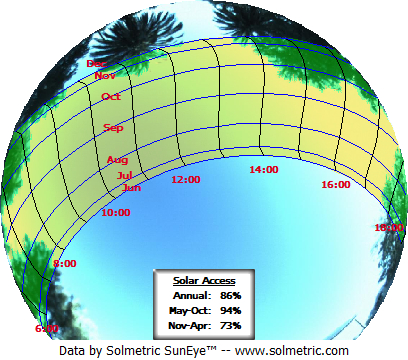
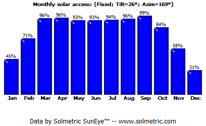
The SunEye is a handheld solar site analysis tool that integrates a fish-eye lens, digital camera, touch-screen interface, and software. This device captures whole-horizon images for a site and generates shading analysis reports on the touch screen for instantaneous feedback. When taking a measurement, you first select your state and nearest city, orient and level the device, and then snap your picture. The touch screen can report the percentage of annual sunlight available and summer versus winter sunlight, along with monthly averages.
Field Assessments
All three tools include bubble levels and compasses and must be leveled and aligned to true south (or north in the Southern Hemisphere) before each measurement. Measurements must be obtained from where the array is intended to be placed. For instance, if a system will be mounted on roof, measurements must be taken from the roof. If a pole-mounted array will be installed, measurements should be taken from a ladder or scaffold set up at the array’s proposed height. For new construction the final assessment may not be possible until roof access is available. However, a preliminary assessment should be done as early as possible in the design process to ensure site potential is promising, or a lift may be used to approximate roof height. In most cases, the layout of a site can determine whether a solar system is feasible (Lisell et al 2009).
Take readings at each corner of the proposed array location, and at the top and bottom to assess the solar window over the entire area. You may find that different portions of the array may be shaded at different times.
The software programs for all three tools can simulate the effect that removing or adding a source of shade has on a potential system—for example, how the solar window could be changed by adding or removing trees, dormers, or other obstructions.
Ensuring Success
The following planning guidance for solar projects is from Lisell, Tetreault, and Watson (2009).
Avoid shading
Shading will have an adverse effect on all the solar technologies discussed here and should be avoided. Use a sun path calculator, such as the Solar Pathfinder™, to assess shading at a particular location by analyzing the sky view where the solar panel will be located. Since the solar application may not be installed for several years, landscaping and future construction should be planned so as to avoid adversely affecting the solar resource.
PV panel performance is exceptionally susceptible to shading. When shade falls on a PV panel, that portion of the panel is no longer able to collect the high-energy beam radiation from the sun. If that shading happens during the peak hours of operation (10 a.m. – 2 p.m.), the production of the panel can be greatly reduced. A PV panel is made up of many individual cells that all produce a small amount of current and voltage. These individual cells are connected in series to produce a larger voltage.
Site Orientation
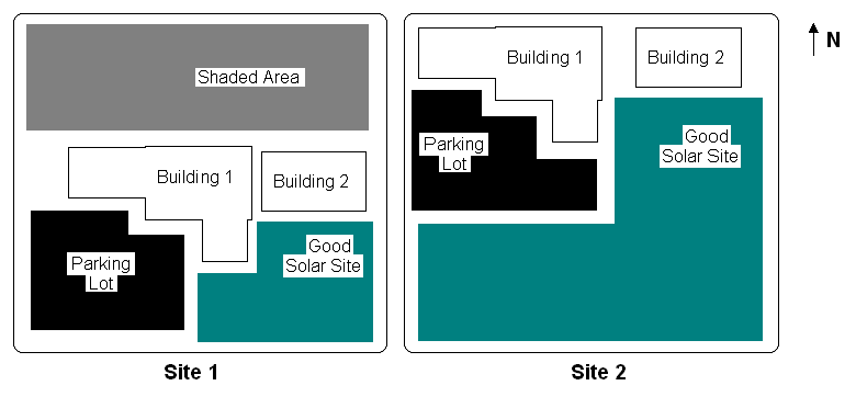
Before ground is broken on a new construction project, consider whether the site layout can be improved to better incorporate a solar system. In most cases, the layout of a site can determine whether a solar system is feasible or not. See Figure 1 for two example scenarios where site layout greatly changes solar potential. In Site 1, a large amount of open space is available north of the buildings, but because of shading from the buildings, the area will be shaded for a large part of the year. In Site 2, the buildings and the parking lot were shifted to the north side of the site. This left the open space on the south side of the site, where shading from the buildings will not fall on the solar panels. By placing the buildings on a site with solar resource and shading in mind, the area available for solar panels can be greatly increased.
If a building is designed with sloped roofs, it is best to orient the roof to maximize the roof area facing south (north-facing in the southern hemisphere). Placement on the south-facing section will ensure that the sunlight will strike the solar collector at a more optimal angle than it would if the collectors are placed on the east-, west-, or north-facing roof sections. The solar panels should be mounted on the south area of the roof and the mechanical equipment and vents should be located on the north area of the roof.
Region
The primary influence of climate on solar assessments comes from the availability of solar resources (amount of sunshine). Climate can also influence the type of solar thermal systems installed. This influence is described in Baechler et al (2007). Geographic influence on solar orientation and inclination are shown in the Description tab. Internet tools are available to help determine available solar resources in general locations.
A first order assessment of available solar resources in geographic areas is available through a few free online tools, such as PVWatts online tool and RETScreen. These tools use historic weather and climate data to estimate the available solar resource, which determines the electrical output and monetary savings for a given system size.
The DOE Zero Energy Ready Home PV-Ready Checklist (Revision 07) is required only under the following condition related to climate (See the Compliance Tab for other exceptions):
- Location, based on zip code, has at least 5 kWh/m2/day average daily solar radiation based on annual solar insolation using the PVWatts online tool. See map below.

Training
Right and Wrong Images
Source
Source
Videos

Compliance
More Info
Case Studies
References and Resources
*For non-dated media, such as websites, the date listed is the date accessed.
Contributors to this Guide
The following authors and organizations contributed to the content in this Guide.
Sales
Solar Electric Ready Home = Solar Electric Ready Home
Technical Description
As solar photovoltaic (PV) panels have significantly come down in price, many homeowners are installing them to produce clean power and reduce their electric bills. Many more homeowners are likely to want this option for the future. Solar electric-ready homes make this possible with minimal to no disruption or cost penalty using simple no-cost/low-cost details and best practices integrated during construction. This includes ensuring adequate unshaded roof space for the PV panels, installing conduit from the attic to the electric service panel, securing documentation that the roof is designed to support the extra weight of the PV array, and providing adequate space near the electrical panel for balance of system components.
Questions? Comments? Contact our webmaster.