

Scope

Retrofit existing older solid masonry homes to withstand seismic activity and include energy retrofits where those retrofits are complimentary with the seismic upgrades.
- Install wall-to-roof diaphragm anchors
- Install wall-to-floor diaphragm anchors
- Install building bracing
- Strengthen diaphragms.
- Install control layers to improve energy efficiency, including a rain control layer, an air control layer, a vapor control layer, and a thermal control layer.
See the Compliance Tab for links to related codes and standards and voluntary federal energy-efficiency program requirements.
Description
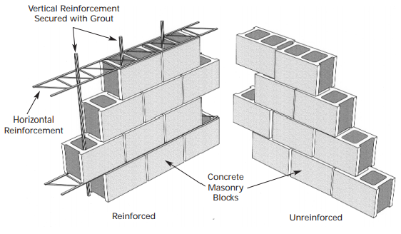
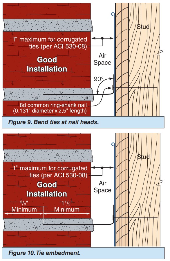
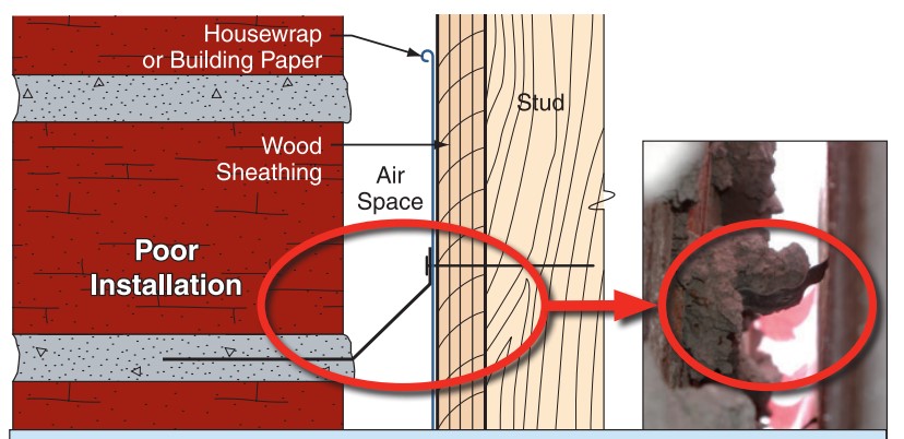
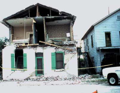
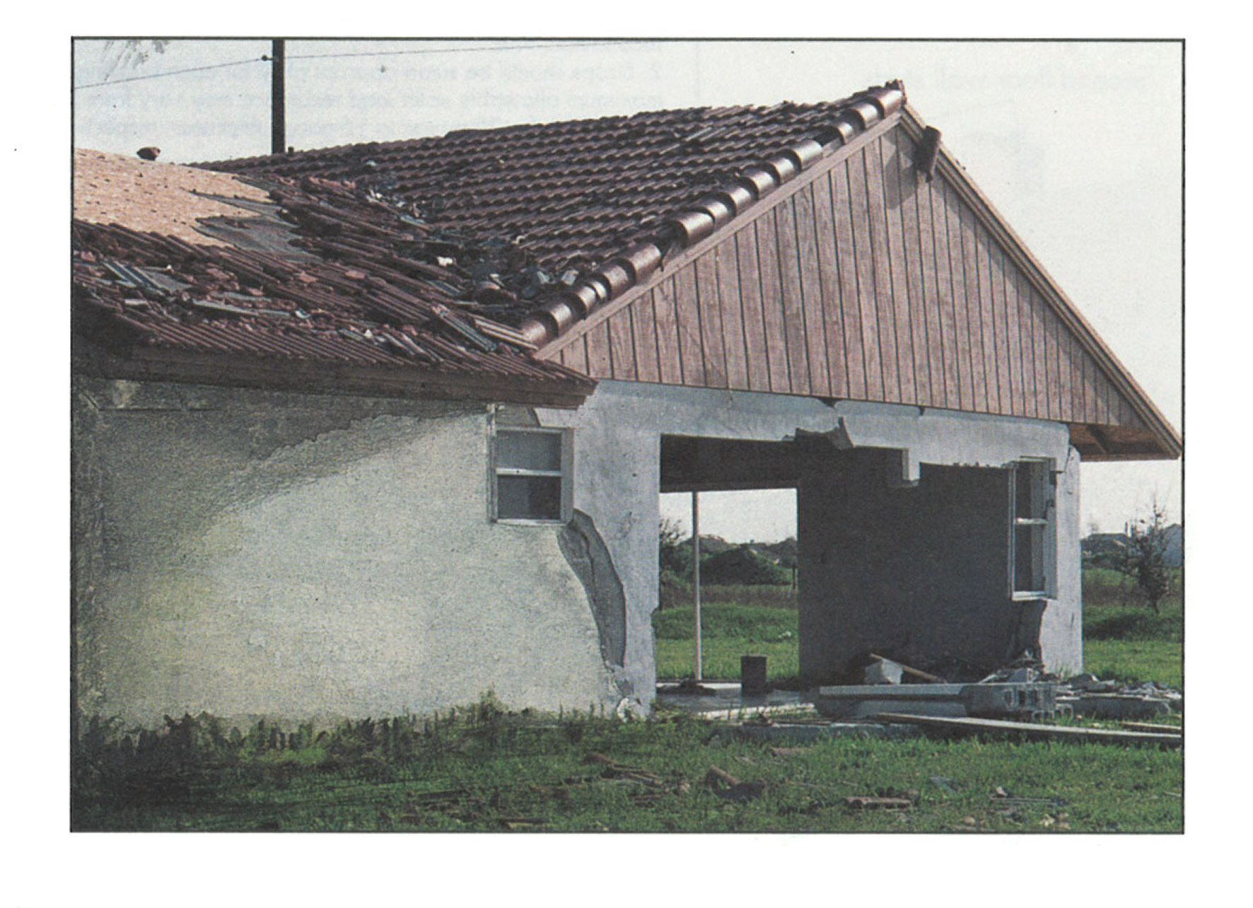
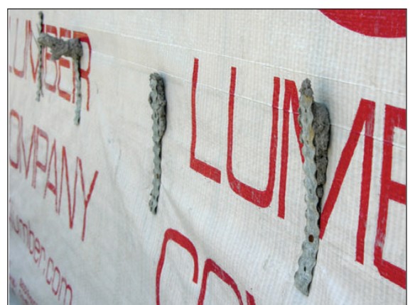
Earthquakes are a major threat to the structural integrity of homes. Existing older brick homes made of unreinforced “solid” masonry walls are particularly vulnerable. These masonry walls might be two or three wythes thick, including an exterior wythe of brick and one or two interior wythes of brick, concrete, or cinder block, mortared and tied together every six courses with metal ties or header bricks. In older homes, if metal ties were used, they were not made of hot-dip or stainless steel so in many cases the ties have rusted away. The walls have no other structural reinforcement, thus making masonry walls especially susceptible to failure in an earthquake.
Many older brick homes also lack insulation, air sealing, and water and vapor control layers. These can be added during a seismic upgrade when they don’t interfere with the seismic reinforcements. In addition to the seismic upgrades discussed below, several options for energy-efficient masonry wall retrofit upgrades are provided at the end of this guide.
Seismic Retrofits of Masonry Walls
Most of the damage to buildings during an earthquake is caused by lateral movement and uplift forces. The basis of all earthquake resistance is to control and transfer the lateral loads (“shear”) caused by ground movement to the foundations and the ground, as well as to address uplift forces.
Figure 1 illustrates a typical older unreinforced masonry home with wood floors and a wood roof. There are several steps that can be taken to improve the ability of such homes to resist seismic activity. Some options are described below.
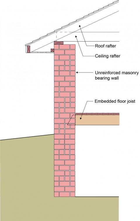
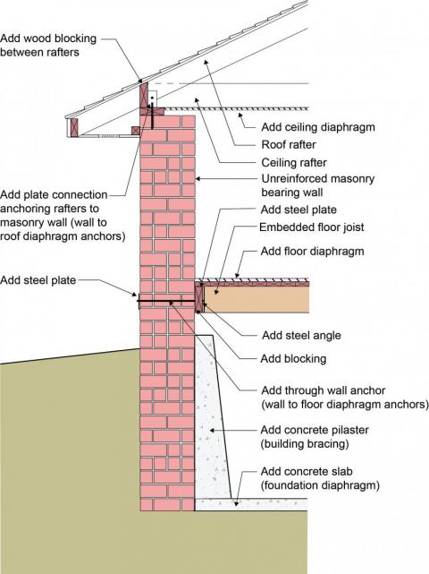
Figure 2 illustrates several steps that can be taken to increase a masonry-walled home’s resistance to seismic forces, including adding blocking between the rafters and installing plate connectors to anchor the rafters to the top of the walls; installing bolt anchors installed with metal plates on the exterior and additional blocking if needed on the interior to connect the brick walls to the floor joists; strengthening diaphragms by adding structural sheathing to the ceiling and subfloor and a basement or crawlspace slab, and adding a concrete pilaster for foundation wall bracing. These retrofit options are all further described below.
Wall-to-Roof Diaphragm Connection
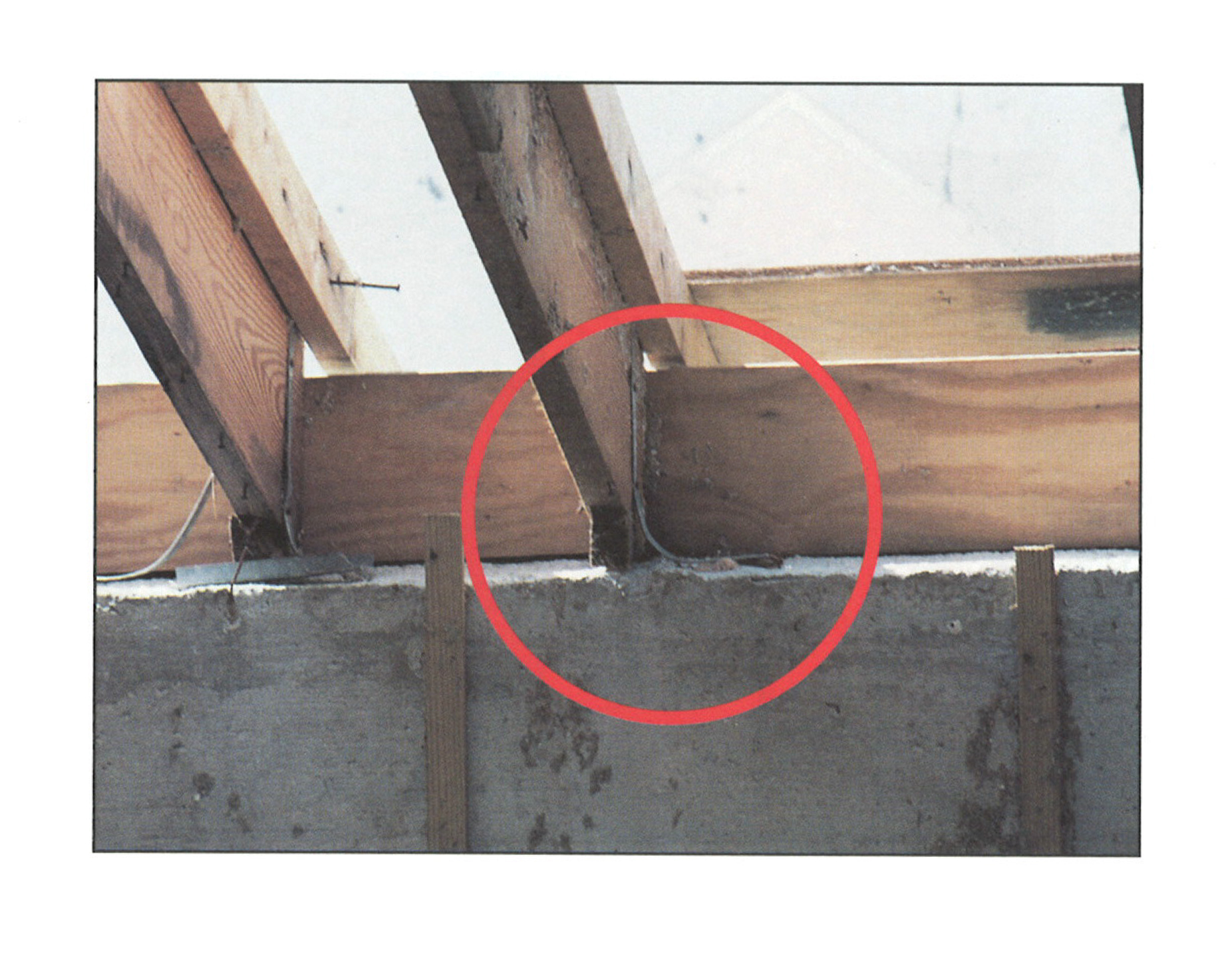
Figure 2 illustrates one retrofit option for strengthening the wall-to-roof connection. Solid wood blocking is added between the roof rafters to prevent the rafters from “racking” or rolling sideways. The roof sheathing should be nailed into the solid wood blocking. In this manner, the blocking also provides a structural connection between the roof sheathing and the top of the wall. The rafters are anchored to the top of the masonry wall with a metal plate connector. A ceiling diaphragm should be added by installing a continuous layer of structural wood sheathing (plywood or oriented strand board “OSB”) on the underside of the rafters.
Note that if this option is used, the solid wood added between the roof rafters may block off the soffit vents. If this occurs, either the attic must be converted to an unvented roof assembly, or alternatively, in homes with gable roofs, inlet vents can be installed low on the gable-end walls.
Wall-to-Floor Diaphragm Connection
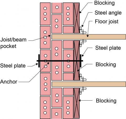
Figure 2 also illustrates the addition of solid wood blocking between the embedded wood floor joists. Figure 3 is a top-down (plan) view of the masonry wall showing how these wood blocks are attached to the floor joists with steel angles. The wood blocks are, in turn, anchored to the masonry wall with through-wall anchors and steel plates. The existing floor diaphragm or subfloor, which will sit on these floor joists and blocking, should be strengthened by adding a continuous layer of structural wood sheathing (plywood or oriented strand board “OSB”) if a solid subfloor is lacking.
Foundation Bracing
Figure 2 also illustrates the addition of concrete pilasters to reduce the likelihood of foundation wall collapse during seismic events. A concrete slab is also added to provide a foundation diaphragm.
Additional building bracing can be added to the field of the unreinforced masonry-bearing walls. Traditional approaches have involved repointing, adding grout, and epoxy injection. More recently, additional building bracing has been achieved by installing a fully adhered reinforcing overlay such as a fiberglass-reinforced laminate, ferrocement (high-strength cement mortar reinforced with layers of fine steel wires), or shotcrete.
Energy Retrofits of Masonry Walls
An energy retrofit can occur at the same time as the seismic retrofit if the project budget and scope allow. The energy retrofit control layers can be added to either the exterior or interior of the masonry walls. Where they occur on the interior side of the solid masonry walls, rain control still must occur on the exterior of the masonry structure.
Exterior retrofits of masonry walls tend to be more energy efficient than interior retrofits. When done from the outside, interior space is not compromised. However, the exterior brick will be covered so community historic preservation requirements or a desire to maintain the “historic look” of the home may constrain the project to only those retrofits that can be done from the interior.
Exterior Energy Retrofits to Existing Masonry Walls
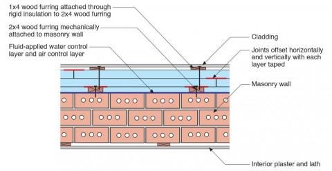
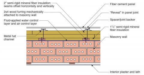
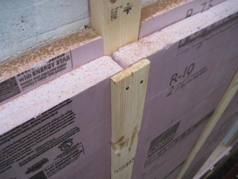
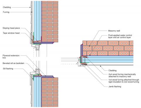
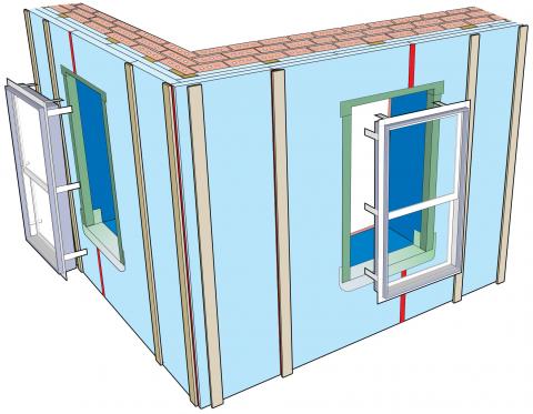
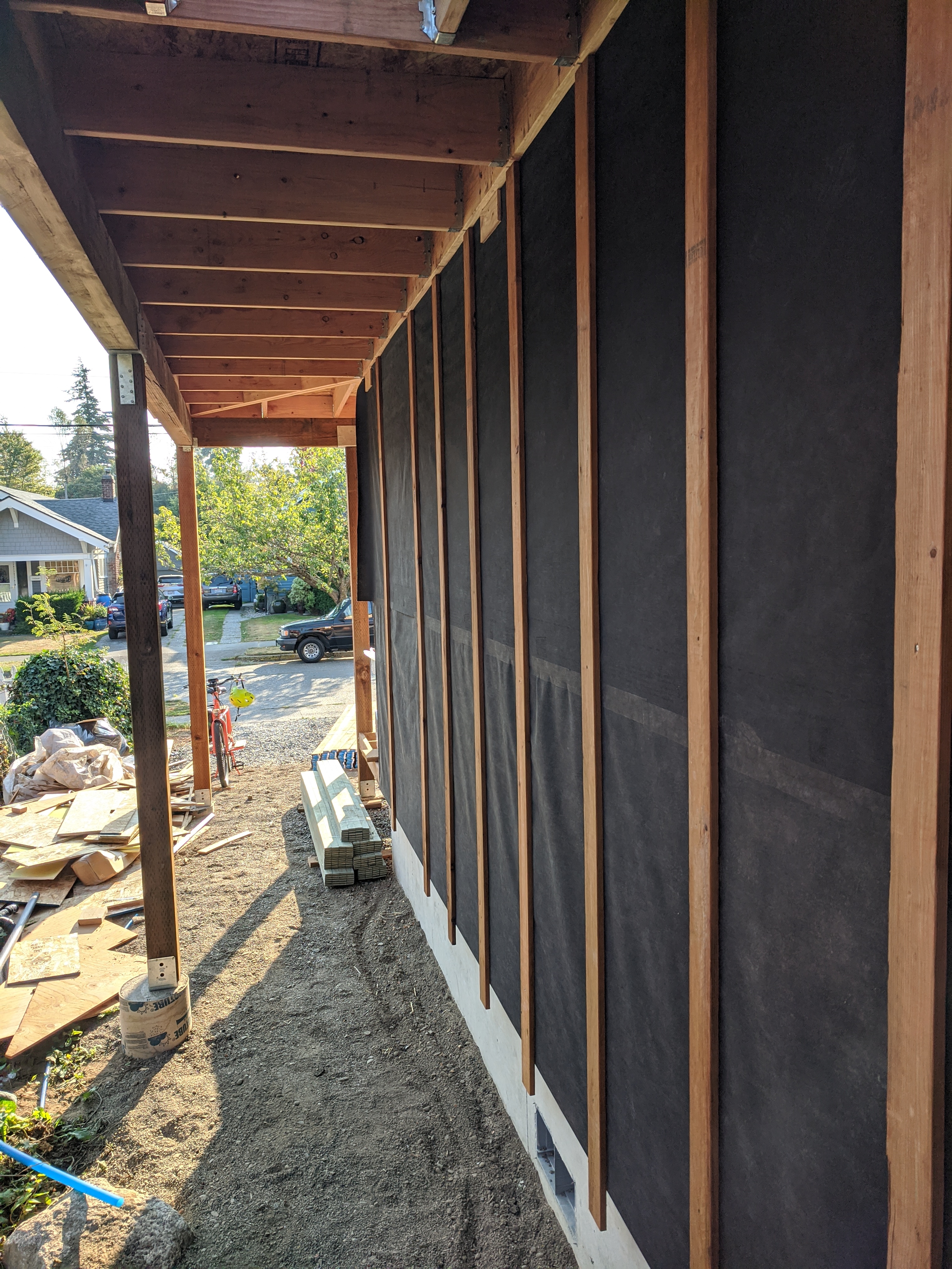
There are several methods for retrofitting solid masonry walls from the exterior. The method described here begins with coating the exterior of the masonry wall with a fluid-applied water and air control layer or “barrier.” Wood furring (2x4s “on the flat”) are installed over this directly to the masonry. Then the entire assembly is insulated by installing one layer of rigid insulation between the furring strips and one or more layers over the furring strips and the first layer of foam. If more than one layer is used (for greater R-value), stagger the seams of the boards and tape the seams in each layer, as shown in Figure 4. Over the rigid insulation, 1x4 furring strips are installed for cladding attachment. These 1x4s are connected to the 2x4 furring with long screws, as shown in Figure 4. Alternatively, metal hat channel can be used as the solid cladding attachment as shown in Figure 5. The insulation can be extruded polystyrene (XPS) as shown in Figure 4 or mineral wool boards as shown in Figure 5, or another rigid board insulation such as expanded polystyrene (EPS), polyisocyanurate, or cork.
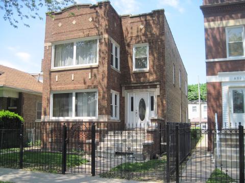
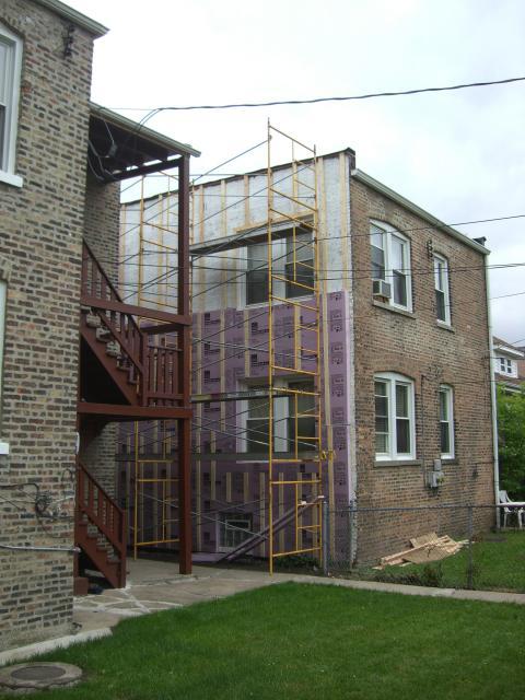
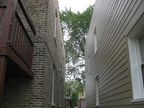
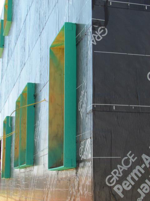
Photograph 1 shows the original brick home before an exterior wall retrofit. Photograph 2 shows the home with the fluid-applied barrier, furring strips, and the first layer of rigid foam installed. Photograph 3 shows two layers of XPS foam and the additional 1x4 furring strips for attaching the cladding. Photograph 4 shows the completed exterior with the new cladding installed, which could be fiber cement, wood, vinyl lap siding, or another option.
With this extensive energy retrofit, the windows will likely be removed and replaced or repositioned after the foam is installed. To install the new windows, the window openings need to be lined with a plywood or OSB extension box that protrudes out past the outward face of the existing masonry to line up flush with the outermost layer of the rigid insulation (Photograph 5). A flanged window unit can be installed with straps that fasten to the interior surfaces of the plywood extension box (Figure 6 and Figure 7). Note that the exterior furring straps adjacent to the window openings are not installed until after the flanged window is mounted and flashed.
Interior Energy Retrofits to Existing Masonry Walls
Masonry walls can be insulated on the interior as a retrofit measure. However, there is a condensation risk at the masonry-to-insulation interface when insulated on the interior. Moisture-laden air that bypasses imperfectly installed interior air control layers (“air barriers”) could condense when it hits the colder brick wall, resulting in moisture problems in the wall assembly. To avoid this problem, excellent airtightness on the interior is essential. Options for installing an air barrier on a mass masonry wall include the application of a liquid-applied air barrier or a membrane and sheet good air barrier on the interior side, or the use of an insulation material that creates an air barrier.
Seven possible approaches for retrofitting a multi-wythe brick or concrete block or clay mass masonry wall by installing insulation on the interior are described below. All of these options use a liquid-applied air barrier to keep interior water vapor from contacting the brick.
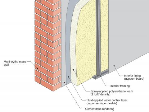
Interior Approach One – Parge Coat, Spray Foam, Service Cavity (Figure 8)
- Cementitious parge coat (“rendering”) on the interior of a mass wall assembly (multi-wythe brick or block or clay tile)
- Fluid-applied water control layer (vapor semi-permeable) on the cementitious rendering
- Spray-applied polyurethane foam (2 lb/ft3 density)
- Interior framing (wood studs or metal studs) creating service cavity
- Interior lining (gypsum wall board and interior finish).
This approach works in all climates with the following limitation – in zones where freeze-thaw damage is a risk, exterior rainwater control (“rain shedding”) must also be employed.
Interior Approach Two – Spray Foam, Service Cavity (Figure 9)
- Fluid-applied water control layer (vapor semi-permeable) on the interior of the mass wall assembly (multi-wythe brick or block or clay tile)
- Spray-applied polyurethane foam (2 lb/ft3 density)
- Interior framing (wood studs or metal studs) creating service cavity
- Interior lining (gypsum wall board and interior finish).
The only alteration from Wall Approach One is the removal of the cementitious parge coat. The use of the parge coat is dependent on the “smoothness” of the interior mass wall surface. Parge can be added to rough interior textures to enable the fluid-applied water control layer to effectively coat the wall surface. This approach works in all climates with the following limitation – in zones where freeze-thaw damage is a risk, exterior rainwater control (“rain shedding”) must be also employed.

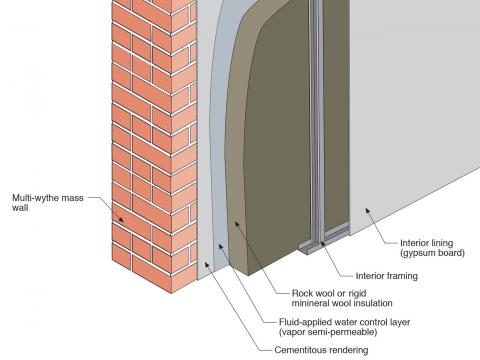
Interior Approach Three – Parge Coat, Mineral Wool Board Insulation, Service Cavity (Figure 10).
- Cementitious parge coat (“rendering”) on the interior of a mass wall assembly (multi-wythe brick or block or clay tile)
- Fluid-applied water control layer (vapor semi-permeable ) on the cementitious rendering
- Rigid mineral wool board sheathing
- Interior framing (wood studs or metal studs) creating service cavity
- Interior lining (gypsum wall board and interior finish).
The alteration from Wall Approach One is the use of rigid mineral wool board sheathing in place of spray polyurethane foam. This approach works in climate zones 4 or lower.
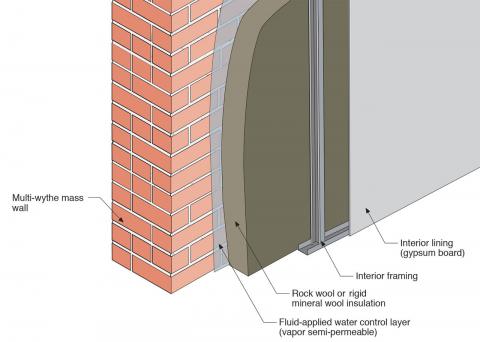
Interior Approach Four - Mineral Wool Board Insulation, Service Cavity (Figure 11)
- Fluid-applied water control layer (vapor semi-permeable ) on the interior of a mass wall assembly (multi-wythe brick or block or clay tile)
- Rigid mineral wool board sheathing
- Interior framing (wood studs or metal studs) creating service cavity
- Interior lining (gypsum wall board and interior finish).
The alteration from Approach One is the removal of the cementitious parge coat and the use of rigid mineral wool board sheathing in place of spray polyurethane foam. This approach works in climate zones 4 or lower.
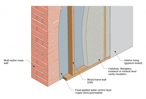
Interior Approach Five – Framed Wall with Cavity Insulation (Figure 12)
- Fluid-applied water control layer (vapor semi-permeable) on the interior of a mass wall assembly (multi-wythe brick or block or clay tile)
- Interior framing (wood frame wall – 2x4 or thicker)
- Cellulose, fiberglass, rockwool or mineral wool insulation cavity insulation
- Interior lining (gypsum wall board and interior finish).
The alteration from Wall Approach One is the removal of the cementitious parge coat, the use of cellulose or fiberglass cavity insulation in place of spray polyurethane foam, and the use of an interior wood frame wall. This approach works in climate zones 4 or lower.
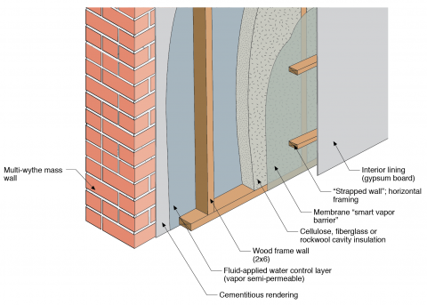
Interior Approach Six – Parge Coat, Framed Wall with Cavity Insulation, Smart Vapor Barrier, Strapped-Wall Service Cavity (Figure 13)
- Cementitious parge coat (“rendering”) on the interior of a mass wall assembly (multi-wythe brick or block or clay tile)
- Fluid-applied water control layer (vapor semi-permeable) on the cementitious rendering
- Wood-framed wall (2x4 or 2x6) insulated with cellulose, fiberglass, rockwool, or mineral wool cavity insulation
- Membrane “smart vapor barrier” installed on the interior of the frame wall
- Second layer of interior framing (“strapped wall”) creating service cavity
- Interior lining (gypsum wall board and interior finish).
This approach works in all climates with the following limitation – in zones where freeze-thaw damage is a risk, exterior rain water control (“rain shedding”) must be also employed.
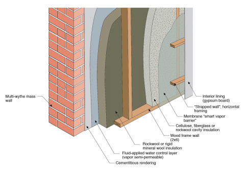
Interior Approach Seven – Mineral Wool Board Insulation, Framed Wall with Cavity Insulation, Smart Vapor Barrier, Strapped-Wall Service Cavity (Figure 14)
- Fluid-applied water control layer (vapor semi-permeable) on the interior of a mass wall assembly (multi-wythe brick or block or clay tile)
- Rigid mineral wool board sheathing
- Wood frame wall (2x4 or 2x6) insulated with cellulose, fiberglass, rockwool or mineral wool cavity insulation
- Membrane “smart vapor barrier” installed on the interior of the frame wall
- Second layer of interior framing (“strapped wall”) creating service cavity
- Interior lining (gypsum wall board and interior finish).
This approach works in all climate zones.
Ensuring Success
Consult a licensed architect or engineer to develop a detailed approach to retrofitting existing older masonry homes to withstand seismic activity. The seismic retrofit can occur in conjunction with energy retrofits where the retrofit approaches are complementary rather than incompatible.
Region
Earthquake Areas
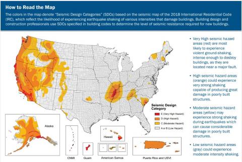
The approaches to seismic control work in all climates. However, check local building codes for specific requirements as seismic risk and requirements vary based on location, see map below. Insulation requirements for thermal efficiency are climate dependent; see the Compliance tab and consult local code for requirements. The approaches for energy retrofits are climate-zone dependent, see the descriptions of each retrofit option for climate guidance.
The International Residential Code (IRC) takes a building’s seismic risk into account based on location. The IRC contours the United States into seismic design categories, from low risk to high risk as shown in Figure 1, which designates the categories by letter: A, B, C, D0, D1, D2, and E, with A designating the lowest risk and E designating areas with the highest risk. The IRC has design guidelines for categories A through D2 as well as scenarios for when a building in design category E can be reassigned to category D2. If a building located in design category E cannot be reassigned to category D2 then it must be designed using the International Building Code (IBC), not the IRC.
Training
Right and Wrong Images
Source
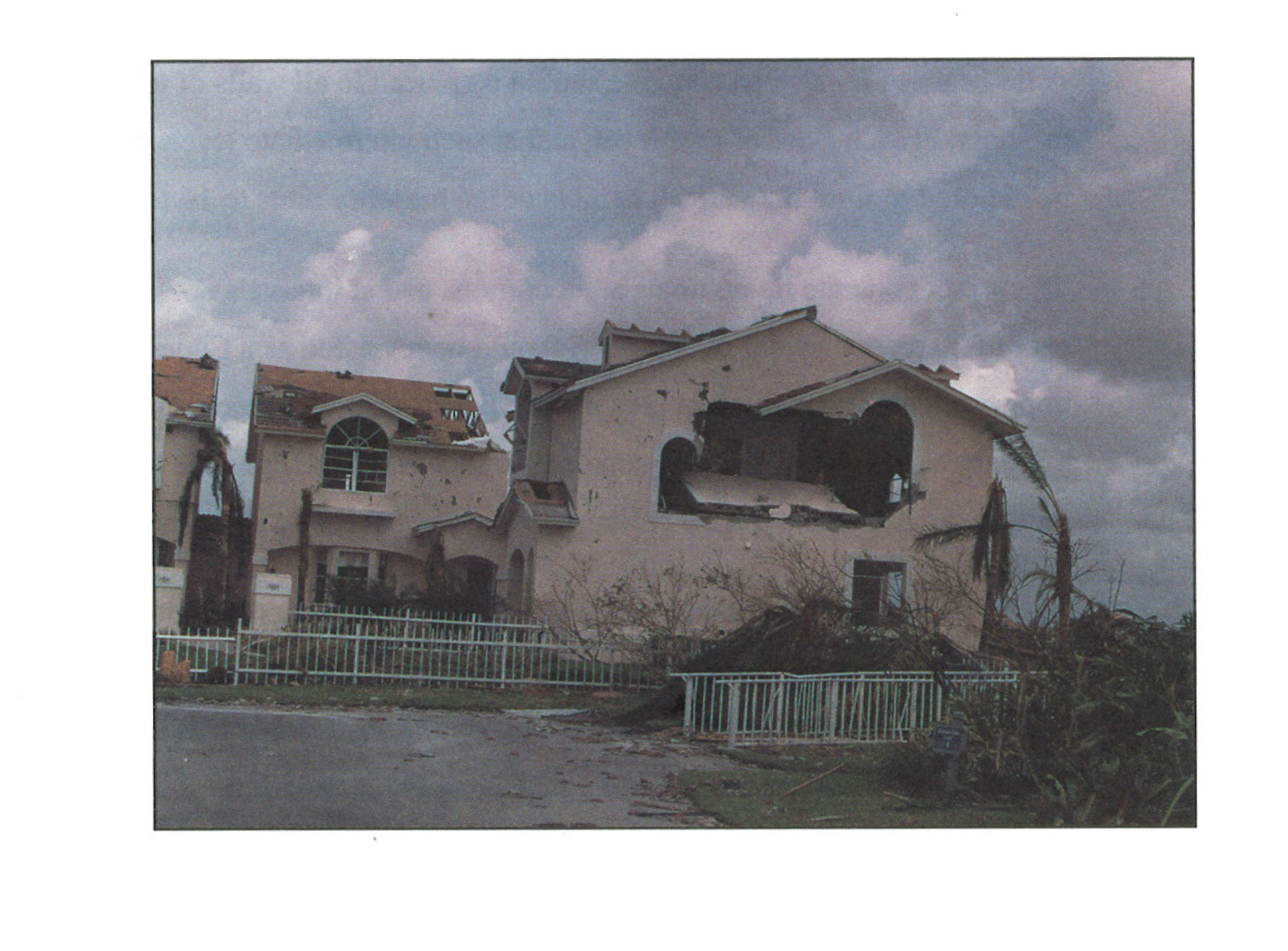
Document containing recommendations on how to brace roofs and gable end walls based on lessons learned from analyzing the destruction from hurricane Andrew.

Source
Guide describing tools for island and hurricane-prone communities on redevelopment and rehabilitation of homes to prepare for future natural disasters.
Source
Document from IBHS explaining how to inspect homes for earthquake preparedness and retrofit solutions for homes that have suffered structural damage as a result of earthquakes.
Source
Report containing 37 fact sheets that provide technical guidance and recommendations concerning the construction of coastal residential buildings.
Source
Report containing 37 fact sheets that provide technical guidance and recommendations concerning the construction of coastal residential buildings.
Source
Document from IBHS explaining how to inspect homes for earthquake preparedness and retrofit solutions for homes that have suffered structural damage as a result of earthquakes.
Source
Document containing recommendations on how to brace roofs and gable end walls based on lessons learned from analyzing the destruction from hurricane Andrew.
Source
Report containing 37 fact sheets that provide technical guidance and recommendations concerning the construction of coastal residential buildings.
Source
Document containing recommendations on how to brace roofs and gable end walls based on lessons learned from analyzing the destruction from hurricane Andrew.
Source
Videos

Compliance
More Info
References and Resources
*For non-dated media, such as websites, the date listed is the date accessed.
Contributors to this Guide
The following authors and organizations contributed to the content in this Guide.
Questions? Comments? Contact our webmaster.