

Scope
When constructing or retrofitting homes with a crawlspace foundation with a “cripple” wall, connect the house walls to the foundation and connect the structural elements to each other to withstand seismic activity.
- Connect the wall to the floor diaphragm.
- Connect the floor diaphragm to the foundation with anchor bolts.
- Install “cripple” wall bracing.
- Install control layers to improve the energy efficiency and durability of the structure, including a rain control layer, an air control layer, a vapor control layer, and a thermal control layer.
See the Compliance Tab for links to related codes and standards and voluntary federal energy-efficiency program requirements.
Description
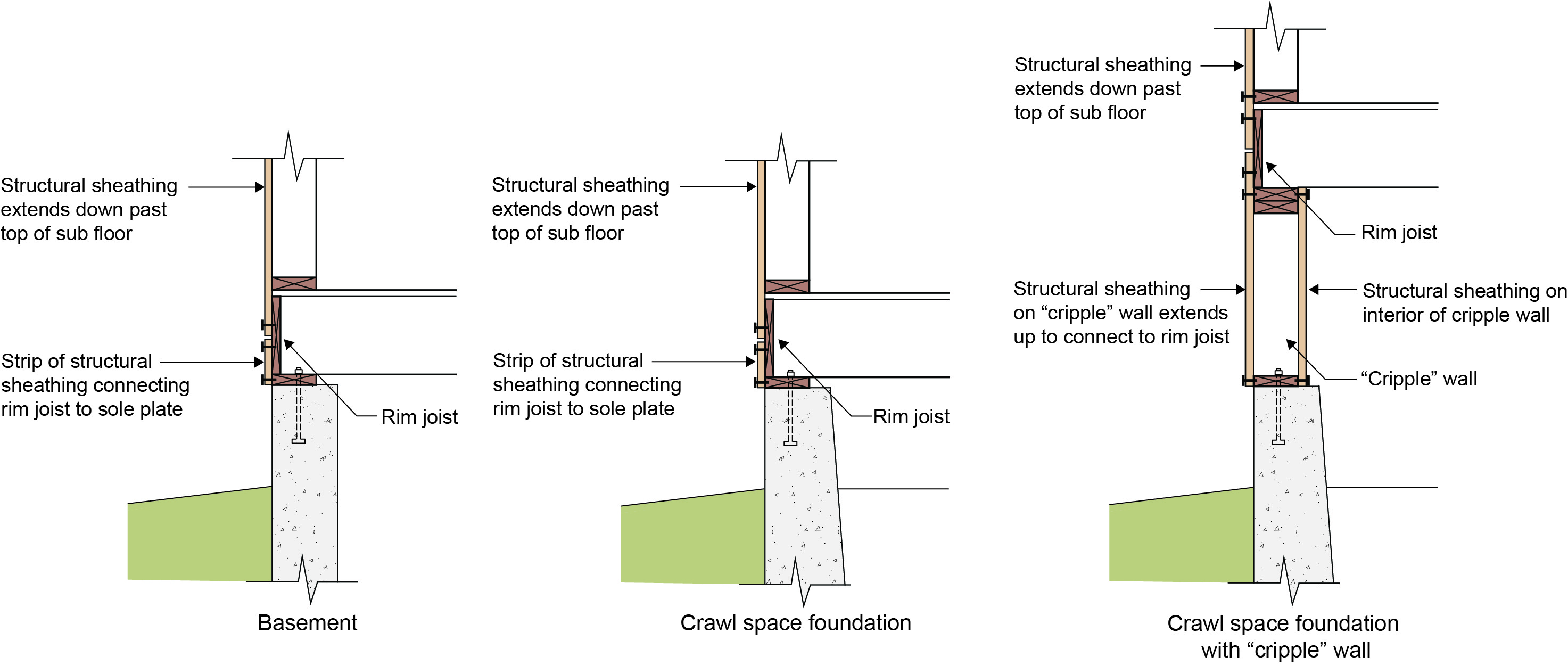
This guide describes options for providing seismic and thermal resistance for homes with a “cripple” wall crawlspace foundation. A cripple wall is a short wall that rests on the foundation and supports the floor and exterior walls (Figure 1).
Seismic Design Approach
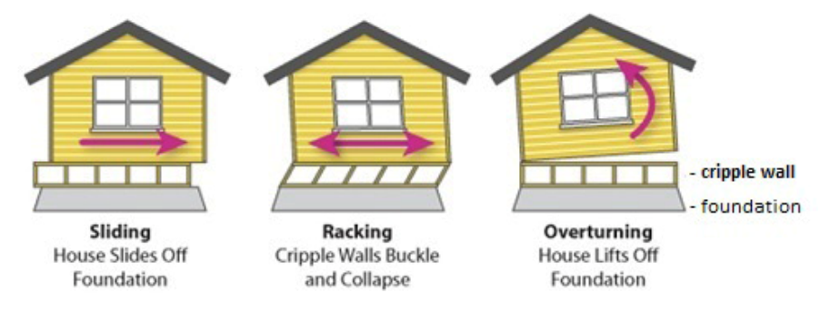
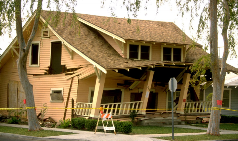
Earthquakes are a major threat to the structural integrity of homes. Most of the damage to a building during an earthquake is caused by lateral movements, which disconnect the house from its foundation. Uplift forces can also occur. These lateral loads (“shear”) and uplift forces due to ground movement need to be transferred to the ground to minimize the likelihood of the building being pulled apart. To withstand seismic stresses, the structural elements should be connected to each other and to the foundation.
Although unrelated to earthquake resistance, when retrofitting a foundation to make it more earthquake resistant, the foundation should also be assessed to see if the insulation, air sealing, and moisture protection could be improved to make the home more thermally efficient and durable.
The following issues should be addressed to improve the ability of new and existing homes with crawlspace foundation cripple walls to resist seismic activity.
Building-to-Foundation Connection
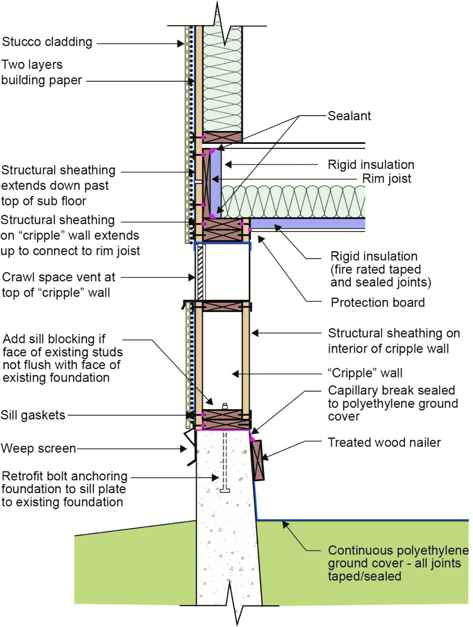
Figure 2 illustrates a construction or retrofit approach for a vented crawlspace foundation with a cripple wall. In the retrofit of crawlspace foundations with cripple walls, the structural connection of the continuous exterior wood sheathing (plywood or oriented strand board [OSB]) to the foundation sill plate is necessary. Also, note that it is recommended that cripple wall retrofits have structural wood sheathing on both sides. Further note the foundation sill plate is connected to the concrete foundation with a foundation anchor bolt. In this manner, the wall and floor diaphragms are connected to each other and to the foundation. It may be necessary to add sill blocking if the interior faces of the existing studs are not flush with the interior face of the existing foundation sill.
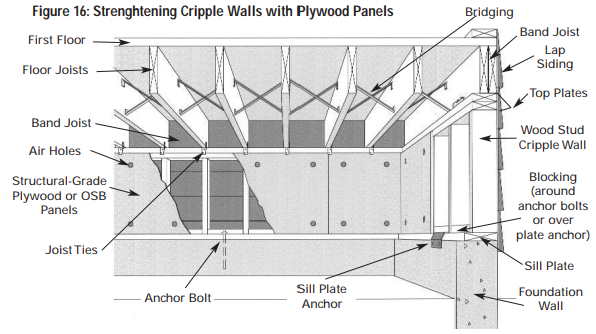
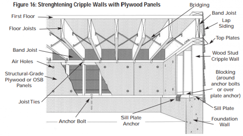
If there are interior posts and piers, additional bracing should be provided by installing cross bracing from the post to the floor beam on both sides of the posts. Floor framing should also have solid blocking of dimensional lumber installed between the floor joists. (The blocking is shown in Figure 3 as the white boxes with black outlines between the floor joists.) The solid wood blocking prevents the floor joists from racking or rolling sideways.
Thermal Efficiency
When retrofitting the cripple wall, take a look at the thermal, air, and moisture control layers; these provide the environmental separation that is the basis for all thermal efficiency. Environmental separation requires a continuous water control layer (rain and groundwater), a continuous air control layer (air barrier), a vapor control layer, and a thermal control layer (insulation).
Figure 2 illustrates one option for installing the environmental separation layers in a vented crawlspace foundation with a cripple wall. In this case, the exterior above-grade wall is covered with stucco.
A continuous water control layer for controlling rainwater consisting of two layers of building paper is installed on the exterior of the wall structural sheathing and is connected to the continuous water control layer on the exterior of the concrete foundation stem wall. The outer layer of the building paper acts as a bond break to facilitate drainage. The bottom of the stucco assembly should have a weep screed that acts as a flashing. The below-grade water control layer, not shown in the figure, could be a fluid-applied waterproofing membrane or dimpled plastic drain mat.
The air control layer of the exterior wall is typically the building paper; in some assemblies, it is a fluid-applied air barrier or house wrap. The air control layer of the underside of the floor framing is the continuous rigid insulation. This rigid insulation should be fire rated and all joints and seams should be taped and sealed. The insulation is sealed to the interior of the perimeter cripple wall framing. The rigid insulation is also protected from animals, rodents, and insects with a protection board, such as fiber cement.
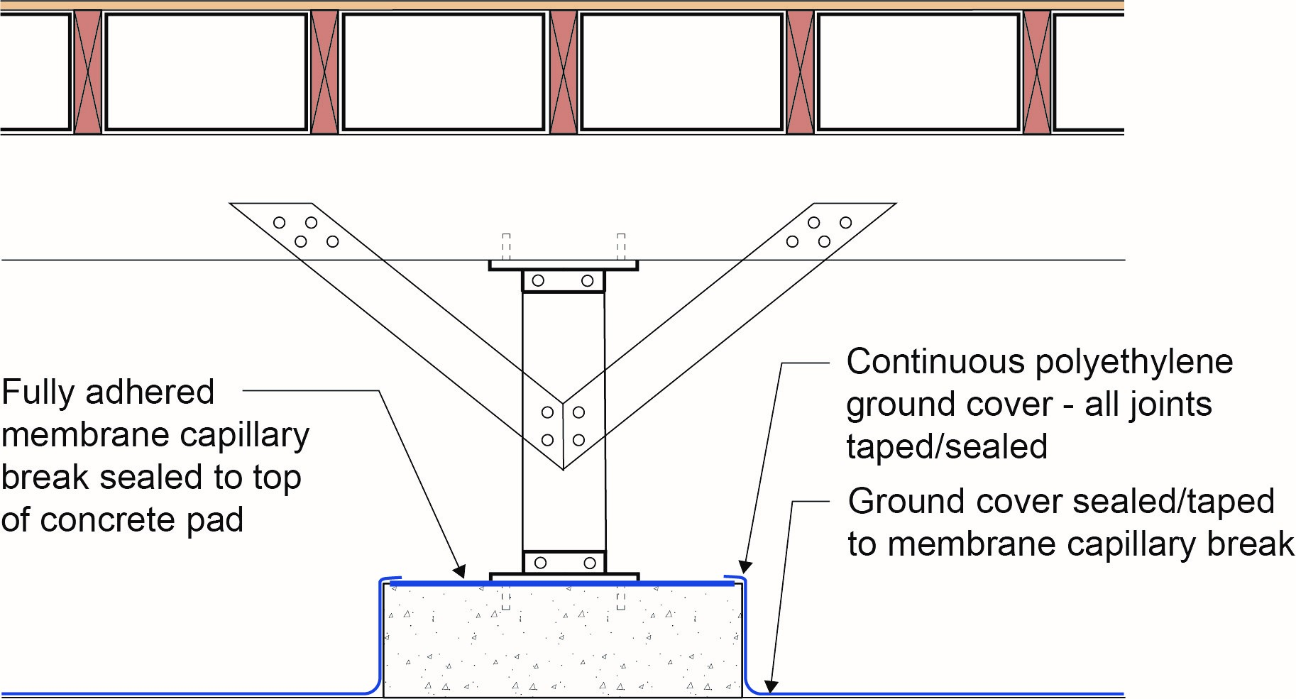
Vapor control is provided by the rigid insulation installed on the underside of the floor framing if foil-faced insulation is used. Additional vapor control is provided by installing a continuous polyethylene ground cover that is connected to the interior of the concrete foundation stem wall and by providing crawlspace ventilation. Figure 4 illustrates the continuity of the polyethylene ground cover at interior posts and piers.
Building code crawlspace ventilation requirements should be met in new and retrofit applications. Most building codes require a minimum net area of ventilation opening of 1 square foot for every1,500 square feet of under-floor area when a Class I vapor retarder is used. The continuous polyethylene ground cover is a Class I vapor retarder. Additionally, the required crawlspace ventilation openings should be placed to provide cross ventilation of the space. It is recommended that at least four ventilation openings be located around the perimeter of the building. Ventilation openings should not be located under low decks or porches.
If a Class I vapor retarder ground cover is not installed, the net ventilation opening area needs to be increased to a minimum of 1 square foot for every 150 square feet of under-floor area. Note that the number of openings and vent area needs to be increased by an order of magnitude and this could adversely affect the ability of the retrofitted cripple wall to resist seismic activity.
Thermal control is provided by the continuous rigid insulation and cavity insulation installed on the underside of the floor framing.
Ensuring Success
Consult a licensed architect or engineer to develop a detailed design and approach for homes to withstand seismic activity. The seismic design can occur in conjunction with thermal efficiency where the approaches are complementary rather than incompatible.
Region
Earthquake Areas
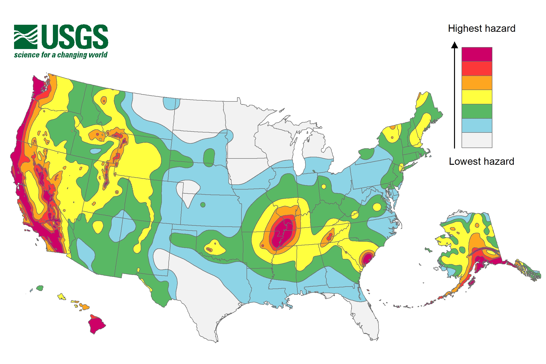
The approaches to seismic control will work in all climates. However, check local building codes for specific requirements as seismic risk and requirements vary based on location; see map below. Insulation requirements for thermal efficiency are climate dependent; see the Compliance tab and consult local code for requirements.
The International Residential Code (IRC) takes a building’s seismic risk into account based on location. The IRC contours the United States into seismic design categories, from low risk to high risk as shown in Figure 1, which designates the categories by letter: A, B, C, D0, D1, D2, and E, with A designating the lowest risk and E designating areas with the highest risk. The IRC has design guidelines for categories A through D2 as well as scenarios for when a building in design category E can be reassigned to category D2. If a building located in design category E cannot be reassigned to category D2, then it must be designed using the International Building Code (IBC), not the IRC.
Training
Right and Wrong Images
Source
Source
Document from IBHS explaining how to inspect homes for earthquake preparedness and retrofit solutions for homes that have suffered structural damage as a result of earthquakes.

Source
Document from IBHS explaining how to inspect homes for earthquake preparedness and retrofit solutions for homes that have suffered structural damage as a result of earthquakes.
Source

Source
Document from IBHS explaining how to inspect homes for earthquake preparedness and retrofit solutions for homes that have suffered structural damage as a result of earthquakes.
Source
Source
Compliance
Retrofit
The approach to seismic retrofit is the same as the approach to new design for seismic resistance. The basis of all earthquake resistance is to control and transfer lateral loads (“sheer”) caused by ground movement to foundations and the ground. The Earthquake Overview Guide in the Building America Solution Center provides extensive guidance on retrofitting measures to strengthen cripple walls.
More Info
References and Resources
*For non-dated media, such as websites, the date listed is the date accessed.
Contributors to this Guide
The following authors and organizations contributed to the content in this Guide.
Building Science Corporation
Pacific Northwest National Laboratory
Questions? Comments? Contact our webmaster.