An official website of the United States government
Here's how you know
Official websites use .gov
A .gov website belongs to an official government organization in the United States.
Secure .gov websites use HTTPS
A lock (
) or https:// means you’ve safely connected to the .gov website. Share sensitive information only on official, secure websites.
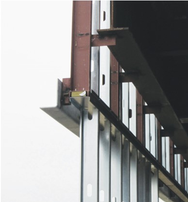
The steel angles on left that will be used to support brick veneer on this multistory building are offset from the steel framing with bracket supports to reduce thermal bridging and allow room to install exterior rigid insulation
Provide design and construction approaches to reduce thermal bridging in mass and steel-framed multifamily buildings. Use rigid exterior insulation, offset supports, nonconductive attachments and other means to address thermal bridging in the following building assemblies:
mass wall assemblies
steel-framed wall assemblies
cladding attachments
balconies
podiums and plazas
slab edges.
See the Compliance Tab for related codes and standards requirements, and criteria to meet national programs.
Description
This guide provides directions for incorporating thermal breaks for mass walls, steel-framed walls, cladding attachments, balconies, and concrete podiums and plazas in multifamily multistory buildings. Foundation insulation is also discussed and approaches are given for providing thermal breaks for post-tensioned slabs as well as for garage ceiling columns and walls. Multistory insulated concrete form (ICF) construction is also discussed.
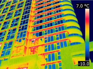
Thermal bridging can occur whenever framing members or attachment devices span through an assembly from within conditioned space to outside the thermal envelope. These framing members or attachments can conduct heat from the hot side of the building to the cooler side, typically outside to inside in summer and inside to outside in winter. See Figure 1 for an example of thermal bridging through the wood wall framing in a single-family home. Thermal bridging can significantly decrease an assembly's effective R-value and adversely affect the thermal performance of the entire assembly. Material choices can greatly impact thermal bridging heat losses. For example, while insulation products have R-values varying from roughly R-3 to R-7 per inch, wood has an R-value of R-1 per inch, concrete has an R value of R-0.1, and steel has an R value of about R-0.003/inch.
This IR camera image of a multifamily building shows extensive thermal bridging at the floor slabs. (Windows appear dark because they are reflecting the cool night sky.)
This IR camera image of a multifamily building shows extensive thermal bridging at the floor slabs. (Windows appear dark because they are reflecting the cool night sky.)
Article describing thermal bridging, construction practices that encourage thermal bridging, and solving thermal bridging through continuous exterior insulation.
Figure 1. This IR camera image of a multifamily building shows extensive thermal bridging at the floor slabs (the windows appear dark because they are reflecting the cool night sky; Source: BSC)
Mass Walls
Mass walls (primarily concrete walls) can be insulated on the exterior or the interior, or both. It is easiest to install rigid insulative sheathing in a fully continuous manner on the exterior, where the surface is easier to access and mostly uniform. By contrast, the interior wall surface is interrupted at floor slabs and locations where interior walls intersect exterior walls, creating installation challenges and slowing the work. Additionally, exterior insulation improves the “time constant” of the building – it takes longer for externally insulated mass assemblies to cool down or heat up in response to changes in exterior temperature.
A mass wall with exterior continuous insulation must still have some sort of cladding. Brick is common but it is heavy and not a good insulator. Also brick requires structural tie-backs (brick ties) to connect to the wall framing or concrete masonry unit (CMU) wall structure. The brick ties can take many forms and numerous products are commercially available. The key to all brick ties is that they need to provide adequate transfer of loads under both positive (windward) and negative (leeward) pressures. As such, flexible corrugated ties should be avoided. Two-piece ties are typical as they allow vertical adjustment. Stainless steel ties provide a significant reduction in thermal bridging compared to typical galvanized steel ties. Other propriety systems such as fiberglass ties are described in the “Cladding Attachment Over Continuous Exterior Insulation” section of this guide.
The exterior insulation can be vapor impermeable (foil-faced polyisocyanurate), vapor semi-impermeable (extruded or expanded polystyrene), or vapor-permeable (mineral wool).
A single, combined air-vapor-water control layer at the exterior of the CMU can be a fully adhered sheet membrane or trowel-on or spray-applied coating. This control layer can be vapor impermeable or vapor semi-impermeable. A mechanically attached weather resistant barrier (house wrap) that is properly overlapped and taped can also be used.
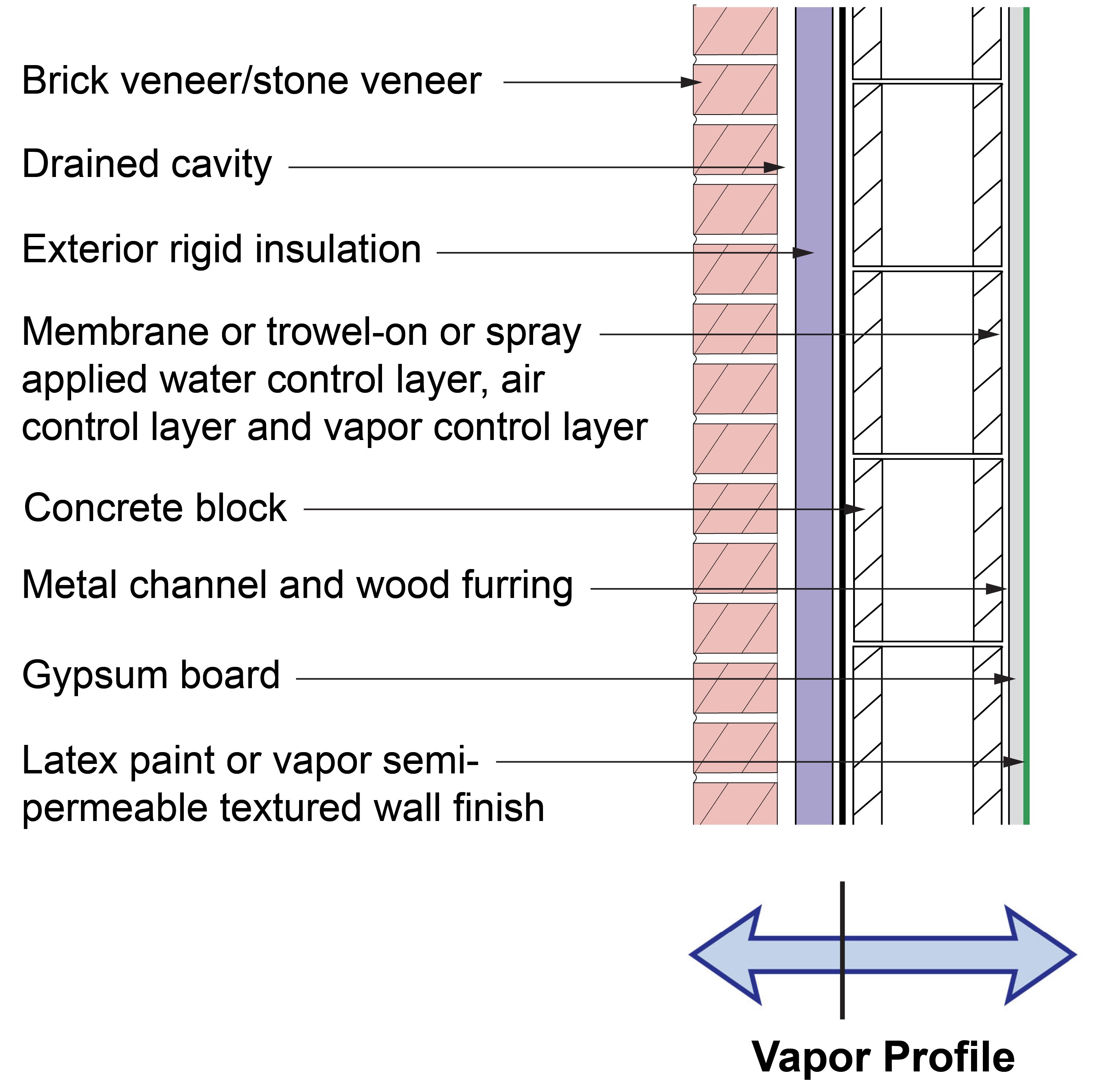
The interior vapor control layer is interior latex paint (which is a Class III vapor retarder). In cold climates, condensation is limited on the interior side of the air, water, and vapor control layers by installing all of the thermal insulation on the exterior side of these control layers. In hot-humid climates, any moisture that condenses on the exterior side of the air-water control layer will be drained to the exterior at the base of the assemblies if flashing is correctly installed. Providing an additional drainage gap behind the exterior insulation is typically not necessary and could reduce the thermal performance of the exterior insulation if convective looping occurs. If a drainage gap is provided, it should be limited to 1/16th inch or less and sealed at the top to control convective heat loss and gains. Ordering the wall assembly layers in this manner prevents moisture from being trapped – and potentially condensing or even freezing – deep within the wall. Water or vapor that originates from the exterior will dry from the vapor control layer to the outside, and moisture that originates from the interior will dry from the vapor control layer inwards, as shown in Figure 2.
This concrete masonry unit (CMU) wall is insulated with rigid insulation on the exterior side of the concrete block
This concrete masonry unit (CMU) wall is insulated with rigid insulation on the exterior side of the concrete block
Figure 2. This concrete masonry unit (CMU) wall is insulated with rigid insulation on the exterior side of the concrete block (Source: Building Science Corporation).
Hydrostatic pressure is controlled by providing a drainage space between the cladding and the insulating sheathing. The ideal solution is to decouple the exterior brick veneer (which is a “reservoir” cladding) from the wall assembly with a ventilated and drained cavity. (In this guide, the term brick veneer does not refer to thin brick façade cladding but to full-sized bricks that are used as a cladding layer that is supported with steel angles and brick ties; the construction method is such that the brick layer provides no structural support to the wall, unlike “double-brick or solid masonry” homes where the brick is part of the building’s structural support.
The cavity behind the brick veneer should be at least 1 inch wide and free from mortar droppings. It must also have air inlets (“weep holes”) at its base and air outlets (“weep holes”) at its top in order to provide back ventilation of the brick veneer.
Figure 2 shows a concrete masonry unit (CMU) wall with exterior insulation and brick or stone veneer. The insulation can be vapor impermeable, semi-permeable, or permeable. It can be constructed in all climate zones and all rain exposure zones. All the insulation is installed outboard of the structure. A combined air-vapor-water control layer is located at the CMU’s exterior surface, inboard of the continuous exterior insulation. The “vapor profile” in Figure 2 shows the impermeable nature of the vapor control layer; bulk water and water vapor cannot pass across this layer. Drying occurs to the exterior from the exterior surface of the vapor control layer and drying occurs to the interior from the interior surface of the vapor control layer.
The minimum thermal resistance of the continuous thermal insulation on the exterior necessary to control condensation is based on the climate zone and is specified in the International Residential Code (IRC) and International Builder Code (IBC). Be sure to calculate the R-value of this layer using the chosen insulation’s rated R-value per inch and the thickness of the material.
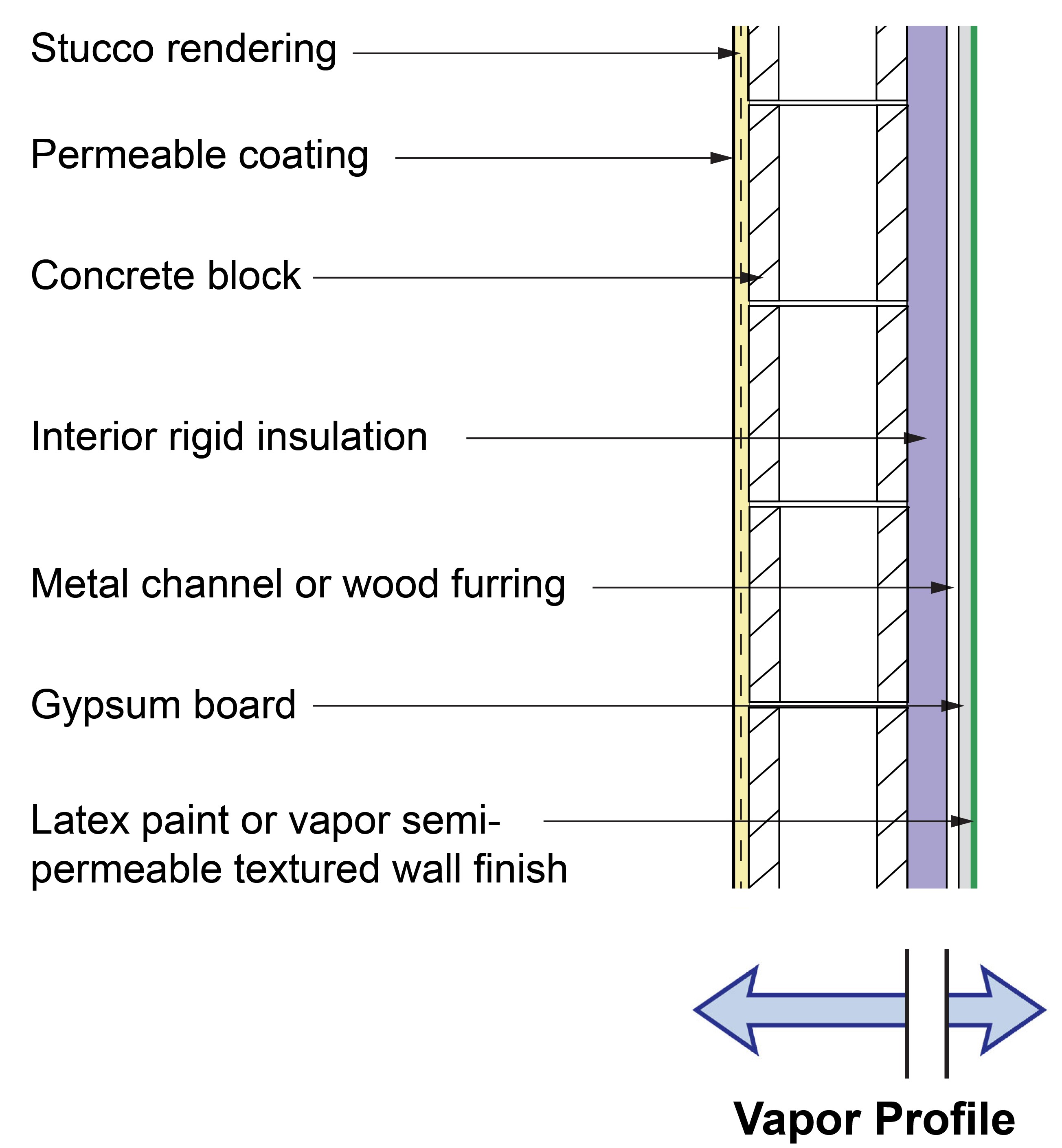
Mass walls can also be insulated on the interior. Figure 3 shows a CMU wall with interior rigid insulation and a stucco cladding layer. It can be constructed in all climate zones and all rain exposure zones.
This concrete masonry unit (CMU) wall is insulated with rigid insulation on the exterior side of the concrete block
This concrete masonry unit (CMU) wall is insulated with rigid insulation on the exterior side of the concrete block
Figure 3. This concrete masonry unit (CMU) wall is insulated with rigid insulation on the exterior side of the concrete block (Source: Building Science Corporation).
This wall has continuous rigid insulation on the inboard side of the CMU wall. The vapor profile indicates where the vapor control layer is in the wall assembly. In this case, the vapor control layer is the rigid insulation. The wall assembly will dry from the interior surface of the vapor control layer (the rigid insulation) inwards and will dry from the exterior surface of the vapor control layer outwards, so long as the exterior finish remains permeable.
The water control layer and the air control layer are the painted stucco rendering on the CMU. The CMU wall behaves as a “mass wall,” storing moisture during rain events then drying during dryer periods. The rigid insulation, which is the vapor control layer and thermal control layer on the interior, can be vapor impermeable (foil-faced polyisocyanurate), vapor semi-impermeable (extruded polystyrene), or vapor-permeable (mineral wool) with an integral vapor control layer. The joints and seams in the interior rigid insulation layer should be taped or otherwise sealed to provide effective vapor control and to limit convective heat gains and heat loss.
The minimum thermal resistance of the continuous thermal insulation on the interior necessary to control condensation is based on the climate zone and is specified in the IRC and IBC codes. Be sure to calculate the R-value of this layer using the chosen insulation’s rated R-value per inch and the thickness of the material.
Steel-Framed Walls
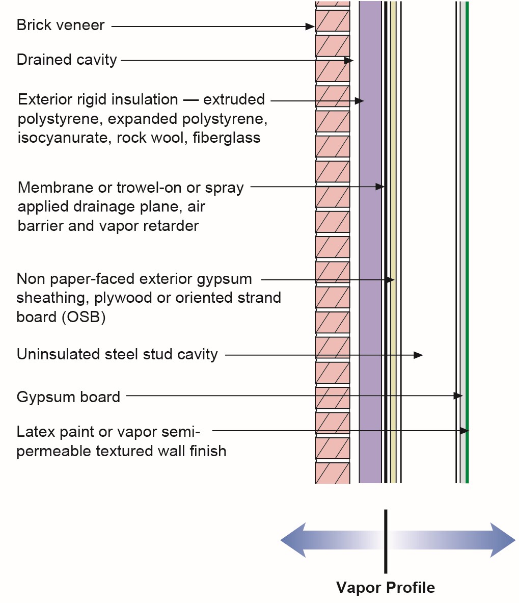
Figure 4 shows a steel-framed wall with exterior insulation and brick or stone veneer and vapor impermeable, semi-permeable, or permeable insulation. It can be constructed in all climate zones and all rain exposure zones.
This steel-framed wall is insulated with rigid insulation on the exterior side of the sheathing
This steel-framed wall is insulated with rigid insulation on the exterior side of the sheathing
Figure 4. This steel-framed wall is insulated with rigid insulation on the exterior side of the sheathing (Source: Building Science Corporation).
In this steel-framed wall, all the insulation is outboard of the structure. As with the mass wall of Figure 2, a combined air-vapor-water control layer is located at the exterior surface of the exterior sheathing, inboard of the continuous exterior insulation.
Hydrostatic pressure is controlled by providing a drainage space behind the cladding. Again, the ideal solution is to decouple the exterior brick veneer (a “reservoir” cladding) from the wall assembly with a ventilated and drained cavity. The cavity behind the brick veneer should be at least 1 inch wide and free from mortar droppings. It must also have air inlets (“weep holes”) at its base and air outlets (“weep holes”) at its top in order to provide back-ventilation of the brick veneer.
Heavy brick veneer is connected to the steel framing with brick ties to resist the negative and positive wind loads. If poorly designed or installed, these may add thermal bridging and reduce the energy performance of the carefully installed exterior continuous insulation layer. The brick ties can take many forms and numerous products are commercially available. The key to all ties is that they need to provide adequate transfer of loads under both positive (windward) and negative (leeward) pressures. As such, flexible corrugated ties should be avoided. Two-piece ties are typical as they allow vertical adjustment. Stainless steel ties provide a significant reduction in thermal bridging compared to typical galvanized steel ties. Other propriety systems such as fiberglass ties are described in the “Cladding Attachment Over Continuous Exterior Insulation” section of this guide.
The exterior insulation can be vapor impermeable (foil-faced polyisocyanurate), vapor semi-impermeable (extruded polystyrene), or vapor permeable (mineral wool).
The combined air, vapor, and water control layer at the exterior surface of the exterior sheathing can be a fully adhered sheet membrane, or a trowel-on or spray-applied coating. It could also be a mechanically attached weather resistive barrier (house wrap) installed to the inside of the exterior rigid insulation and properly overlapped and taped. (House wrap could also be installed to the outside of the rigid insulation but it is much more susceptible to wind displacement during construction.) The continuous rigid insulation could also serve as the air, vapor, and water control layer if all seams are taped with a properly applied, compatible tape. This control layer can be vapor impermeable or vapor semi-impermeable.
The interior vapor control layer is interior latex paint (a Class III vapor control layer). In cold climates installing all of the thermal insulation on the exterior side of these control layers keeps temperatures throughout the wall cavity above dewpoint to avoid condensation and even freezing. Bulk water would not be able to pass back through the wall to the interior space, but water vapor can. In hot-humid climates, any moisture that condenses on the exterior side of the air-water control layer will be drained to the exterior at the base of the assemblies if the flashing is properly installed. Providing an additional drainage gap behind the exterior insulation is typically not necessary. If a drainage gap is provided behind the exterior continuous insulation, it should be limited to 1/16th inch or less to control convective heat losses and gains. Ordering the wall assembly layers in this manner prevents moisture from being trapped – and potentially condensing – deep within the wall. Water or vapor that originates from the exterior will dry from the vapor control layer to the outside, and moisture that originates from the interior will dry from the vapor control layer inwards, as shown in Figure 3.
The minimum thermal resistance of the continuous thermal insulation on the exterior necessary to control condensation is based on the climate zone and is specified in the IRC and IBC codes. Be sure to calculate the R-value of this layer using the chosen insulation’s rated R-value per inch, and the thickness of the material.
Cladding Attachments
The most prevalent thermal bridging occurs where claddings are supported or attached to the walls of a multistory building. One example of this is horizontal steel angle supports used to support brick veneers; these supports are typically bolted through the wall at the floor slabs for each floor. Another example is the steel Z-bars that pass through the wall to connect the exterior cladding with the steel framing; even if the wall has exterior continuous insulation the steel Z-bar can be a significant source of heat transfer. Using clips and screws instead can greatly reduce the amount of metal, and therefore heat transfer, through the wall.
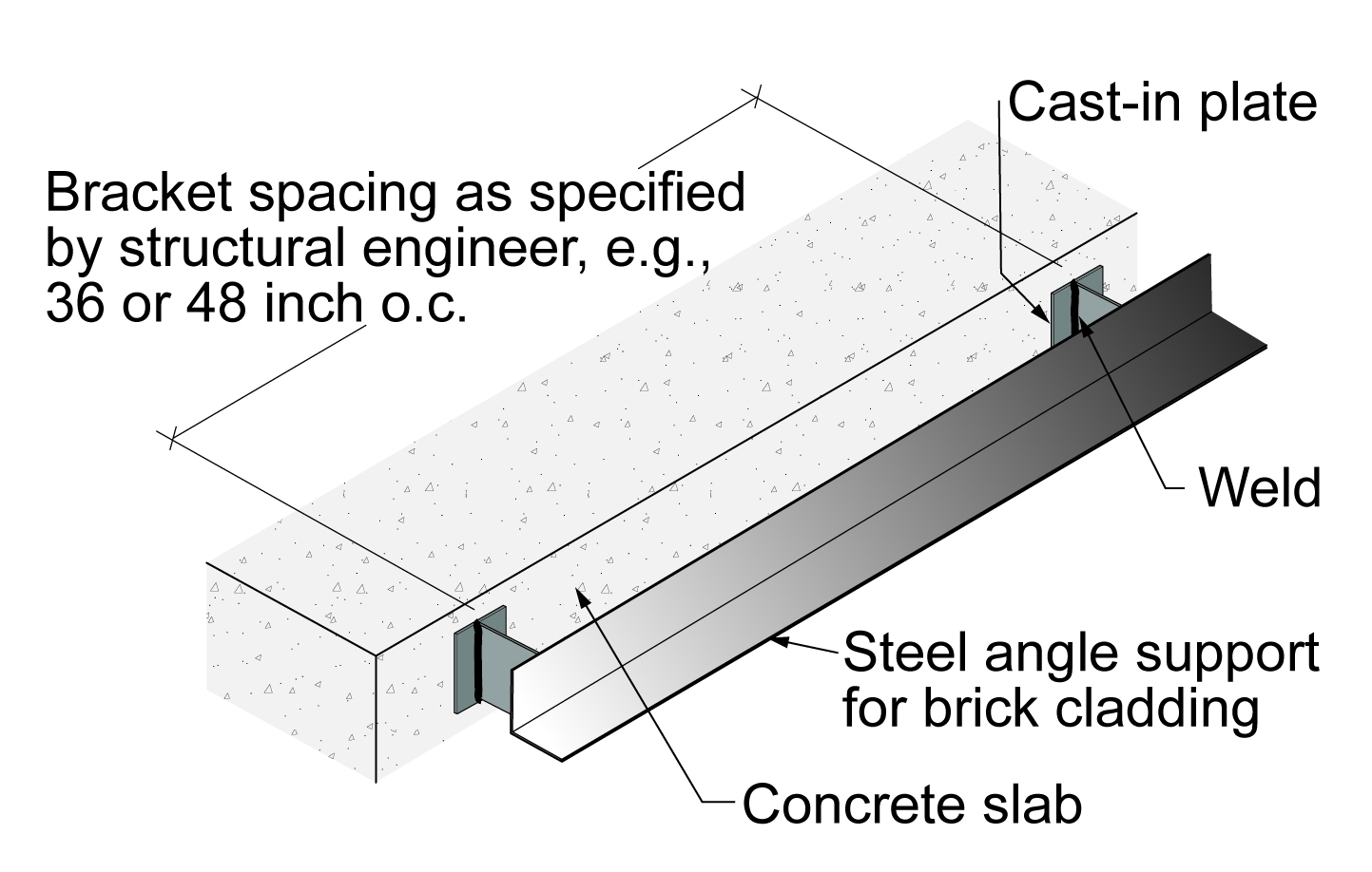
Brick Veneer Supports
Brick veneers are typically supported at slab edges by steel angles. When steel angles are directly attached to the slab edges, significant thermal bridging occurs in direct relation to the cross-sectional area of the through-connection, and how deeply the fasteners penetrate. Control of this thermal bridging typically involves off-setting the steel angles from the slab edges with bracket supports (shown in Figures 4 through 7). Off-setting the steel angles reduces the thermal contact area of the steel angles and allows insulation to be installed between the steel angles and the slab edges and wall structure. The reduction in thermal bridging is considerable – typically more than 75%.
Steel angles for supporting brick veneer are offset from the concrete floor slabs of a multistory building with bracket supports to reduce thermal bridging and provide space to install insulation between the steel angles and the slab edges
Steel angles for supporting brick veneer are offset from the concrete floor slabs of a multistory building with bracket supports to reduce thermal bridging and provide space to install insulation between the steel angles and the slab edges
Figure 5. Steel angles for supporting brick veneer are offset from the concrete floor slabs of a multistory building with bracket supports to reduce thermal bridging and provide space to install insulation between the steel angles and the slab edges (Source: Building Science Corporation).
Steel angles for supporting brick veneer are offset from the concrete floor slabs of a multistory building by standoffs to reduce thermal bridging and allow room for rigid exterior insulation between the steel angles and the slab edges
Steel angles for supporting brick veneer are offset from the concrete floor slabs of a multistory building by standoffs to reduce thermal bridging and allow room for rigid exterior insulation between the steel angles and the slab edges
Figure 6. Steel angles for supporting brick veneer are offset from the concrete floor slabs of a multistory building by standoffs to reduce thermal bridging and allow room for rigid exterior insulation between the steel angles and the slab edges (Source: Building Science Corporation).
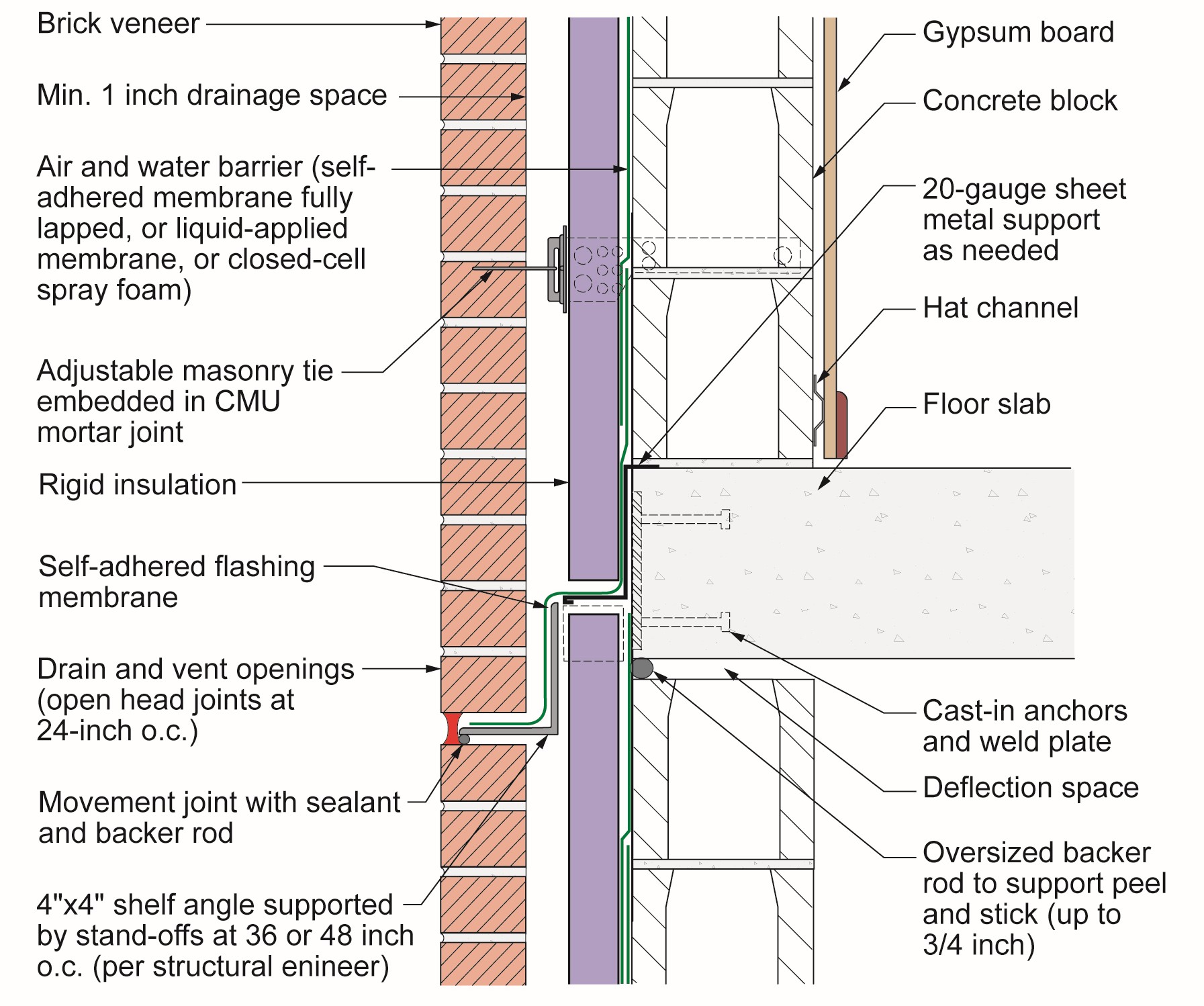
Note in Figure 6 the gap between the top of the CMU “back-up wall” and the underside of the structural concrete slab. This gap accounts for “concrete creep” that occurs over time in multi-story concrete column/slab buildings. Also note the movement joint (“soft joint”) in the brick veneer under the shelf angle for the same reason. Over time, concrete frame buildings “shrink.” They are slow-moving amorphous solids that deform under sustained loads. Also, over time, brick expands due to irreversible moisture expansion. The shrinkage of the concrete frame in multi-story buildings when combined with irreversible moisture expansion in brick veneers necessitates “control joints.” Further note that concrete creep in multi-story buildings also affects stucco claddings – hence the requirement for stucco control joints. It is also worth noting that the flashing over the shelf angle is installed shingle fashion to encourage drainage down and out of the wall assembly.
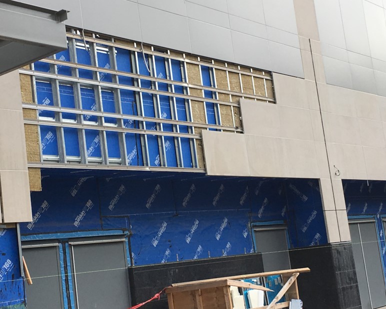
The steel angles on left that will be used to support brick veneer on this multistory building are offset from the steel framing with bracket supports to reduce thermal bridging and allow room to install exterior rigid insulation
The steel angles on left that will be used to support brick veneer on this multistory building are offset from the steel framing with bracket supports to reduce thermal bridging and allow room to install exterior rigid insulation
Figure 7. The steel angles on left that will be used to support brick veneer on this multistory building are offset from the steel framing with bracket supports to reduce thermal bridging and allow room to install exterior rigid insulation between the brick veneer and the steel framing (Source: Building Science Corporation).
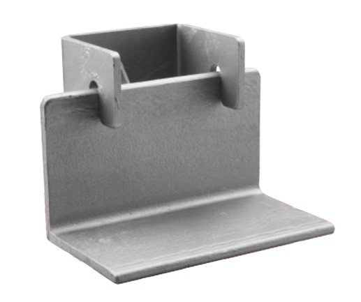
This steel angle used for installing brick veneer on a multistory building is attached to the building with steel “clip” bracket supports that offset the angle from the framing to reduce thermal bridging and provide room for exterior insulation
This steel angle used for installing brick veneer on a multistory building is attached to the building with steel “clip” bracket supports that offset the angle from the framing to reduce thermal bridging and provide room for exterior insulation
Figure 8. This steel angle used for installing brick veneer on a multistory building is attached to the building with steel “clip” bracket supports that offset the angle from the building framing to reduce thermal bridging and provide room for exterior insulation (Source: Building Science Corporation).
Steel Z-Bar Cladding Attachments
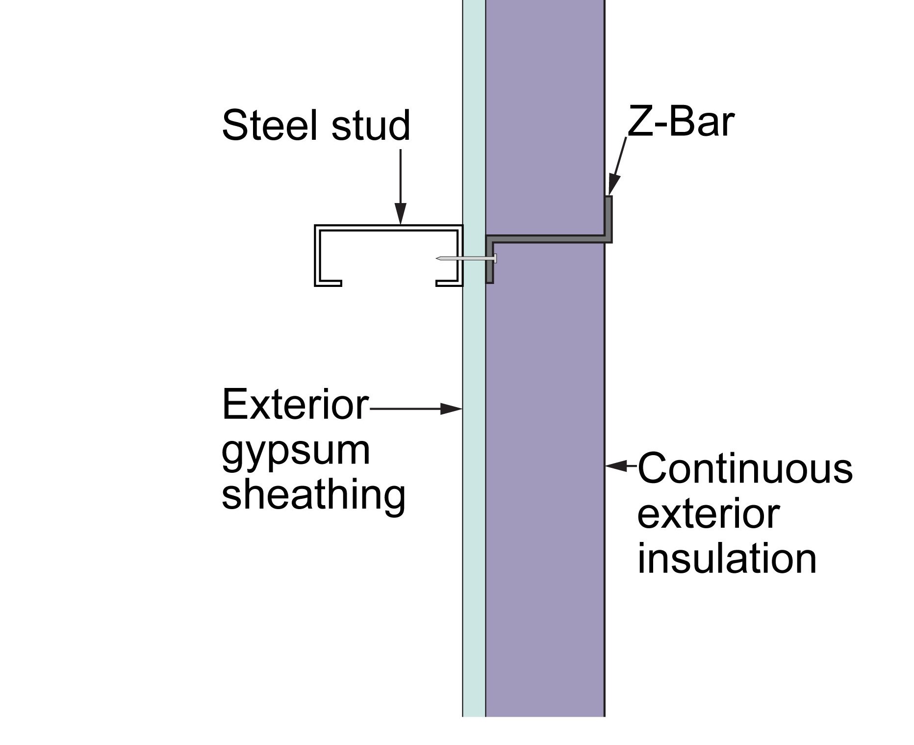
Where steel Z-bars or cold-formed anchors and clips are used to provide connection between the cladding and the structural components of the wall, the thermal bridging can be significant if the full length of the steel Z-bar or cold-formed anchor is directly attached through the exterior sheathing and to the wall framing (Figures 8 and 9). Over 50% of the thermal resistance of the continuous insulation can be lost. These approaches should be avoided.
This image shows a cross section of a vertical Z-bar cladding anchor that forms a thermal bridge through the insulation to the steel wall studs and should be avoided
This image shows a cross section of a vertical Z-bar cladding anchor that forms a thermal bridge through the insulation to the steel wall studs and should be avoided
Figure 9. This image shows a cross section of a vertical Z -bar cladding anchor that forms a thermal bridge through the insulation to the steel wall studs and should be avoided (Source: Building Science Corporation).
The vertical Z-bar passes lengthwise through the sheathing and forms a significant thermal bridge through the insulation to the steel wall studs; it should be avoided
The vertical Z-bar passes lengthwise through the sheathing and forms a significant thermal bridge through the insulation to the steel wall studs; it should be avoided
Figure 10. The vertical Z-bar passes lengthwise through the sheathing and forms a significant thermal bridge through the insulation to the steel wall studs; it should be avoided (Source: Building Science Corporation).
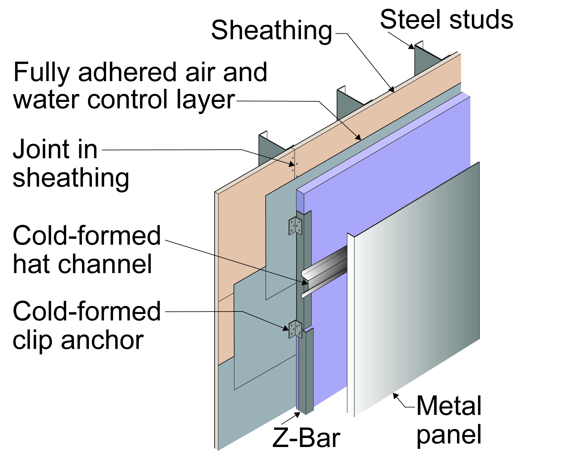
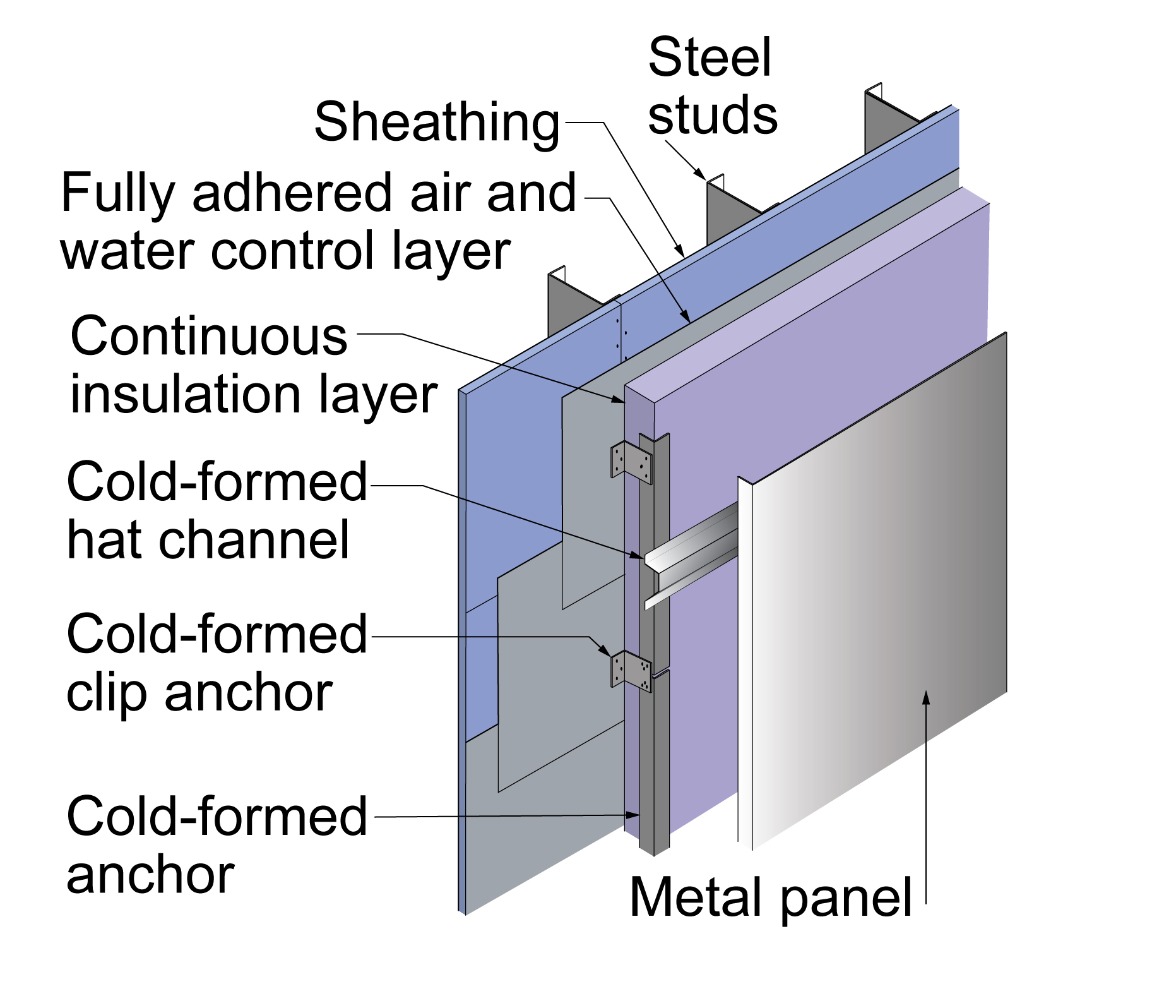
Using a cold-formed anchor that doesn’t pass through the sheathing and attaching that anchor to the studs with clip anchors can significantly reduce thermal bridging (Figure 11). Note the hat channel could also be installed vertically over horizontal anchor supports to aid in drainage and ventilation behind the cladding.
Thermal bridging can be reduced when attaching metal panel cladding to a metal-framed building by attaching the cladding to hat channel that is attached to vertical anchors with clip anchors and screws through the sheathing to the steel studs
Thermal bridging can be reduced when attaching metal panel cladding to a metal-framed building by attaching the cladding to hat channel that is attached to vertical anchors with clip anchors and screws through the sheathing to the steel studs
Figure 11. Thermal bridging can be reduced when attaching metal panel cladding to a metal-framed building by attaching the cladding to hat channel that is attached to vertical anchors with clip anchors and screws through the sheathing to the steel studs (Source: Building Science Corporation).
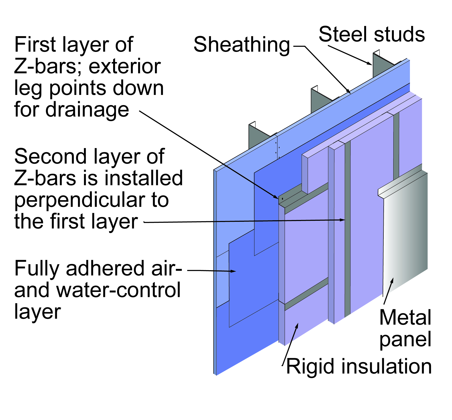
Using two layers of Z-bars offset horizontally and vertically also significantly reduces thermal bridging (Figure 12).
Exterior cladding on a metal-framed building is attached using two perpendicular layers of offset Z-bar to reduce thermal bridging
Exterior cladding on a metal-framed building is attached using two perpendicular layers of offset Z-bar to reduce thermal bridging
Figure 12. Exterior cladding on a metal-framed building is attached using two perpendicular layers of offset Z-bar to reduce thermal bridging (Source: Building Science Corporation).
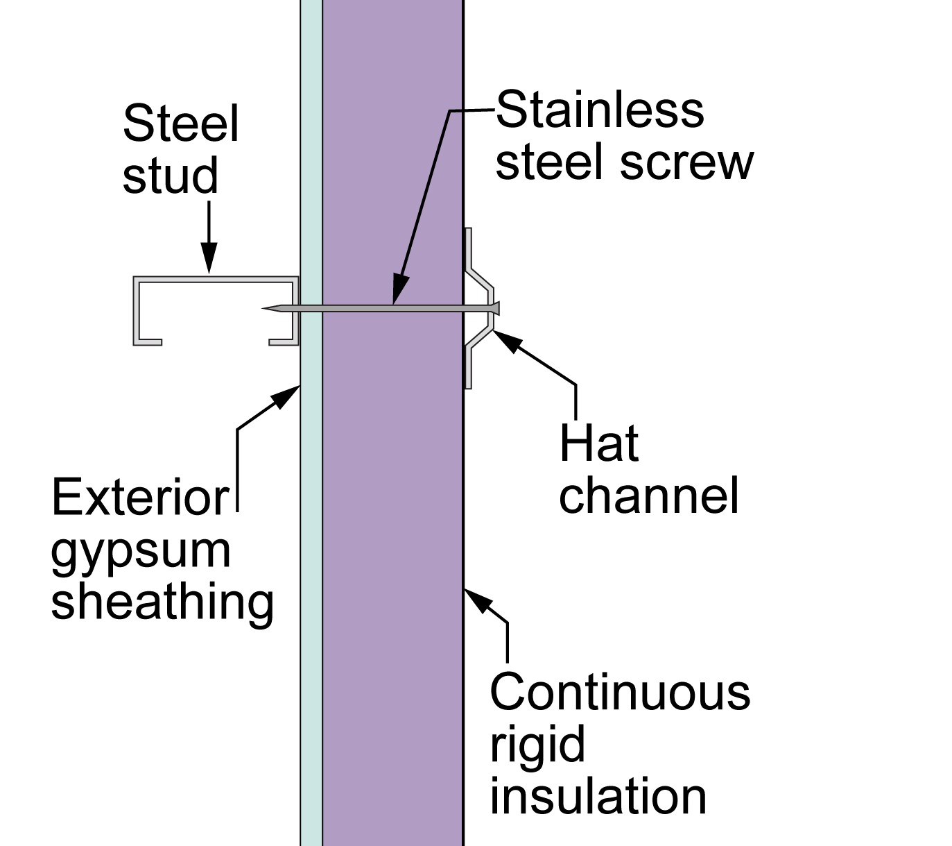
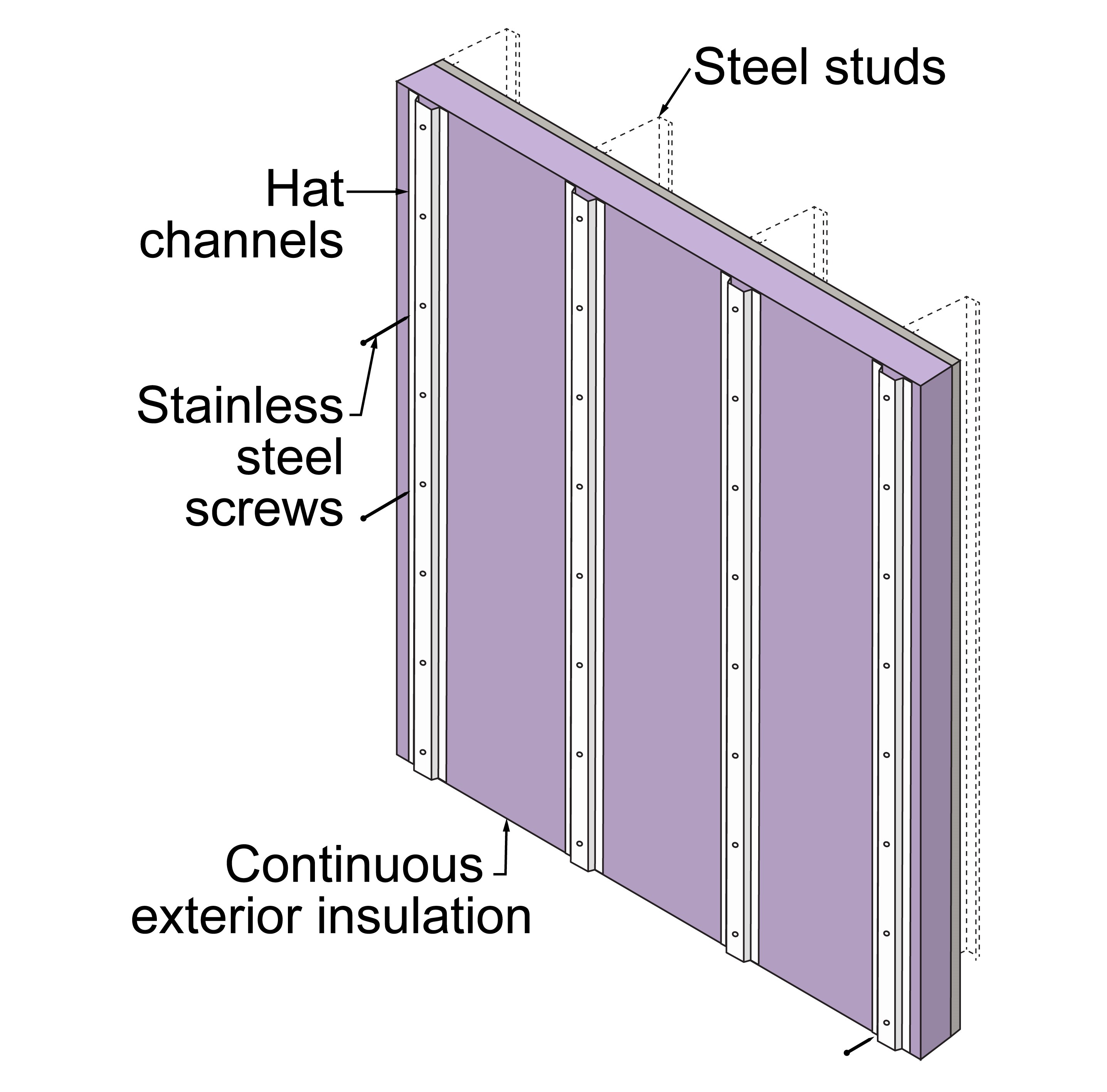
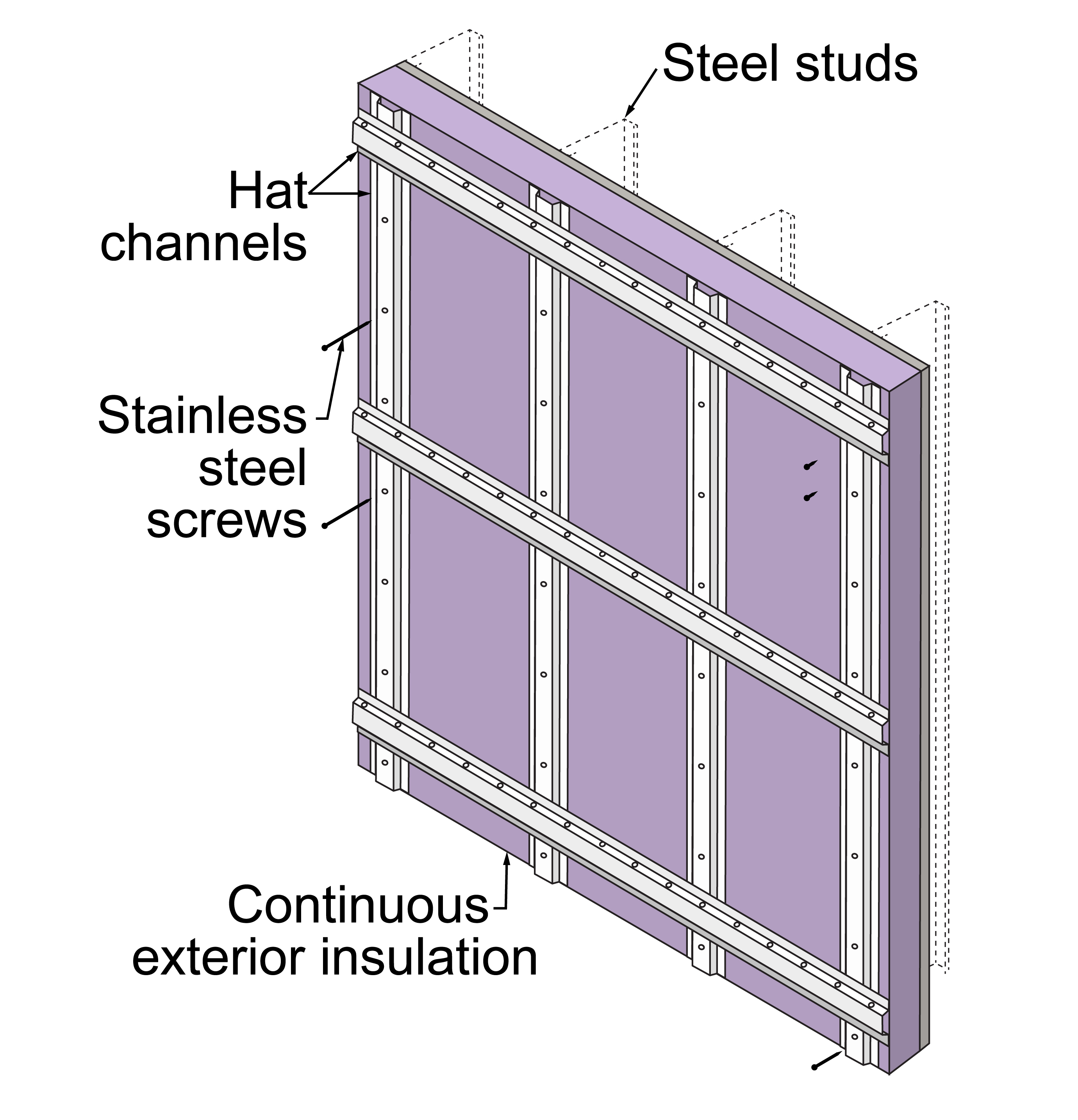
Using long stainless-steel screws and “hat channel” installed over continuous exterior insulation provides excellent control of thermal bridging when attaching exterior cladding to steel framing (Figures 12 and 13). Adding a second “hat channel” layer at 90-degrees creates a strong matrix that increases rigidity and provides a deeper drainage gap (Figure 15).
Use stainless steel screws and hat channels to attach cladding to metal-framed buildings while minimizing thermal transfer
Use stainless steel screws and hat channels to attach cladding to metal-framed buildings while minimizing thermal transfer
Figure 13. Use stainless steel screws and hat channels to attach cladding to metal-framed buildings while minimizing thermal transfer (Source: Building Science Corporation).
Use hat channels attached to the steel studs with stainless steel screws through the rigid foam to attach cladding with less thermal bridging
Use hat channels attached to the steel studs with stainless steel screws through the rigid foam to attach cladding with less thermal bridging
Figure 14. Use hat channels attached to the steel studs with stainless steel screws through the rigid foam to attach cladding with less thermal bridging (Source: Building Science Corporation).
A double layer of hat channels installed at 90-degrees to each other with stainless-steel screws through the rigid foam to anchor cladding to steel studs with less thermal transfer; the second layer of hat channels provides increased rigidity
A double layer of hat channels installed at 90-degrees to each other with stainless-steel screws through the rigid foam to anchor cladding to steel studs with less thermal transfer; the second layer of hat channels provides increased rigidity
Figure 15. A double layer of hat channels installed at 90-degrees to each other with stainless-steel screws through the rigid foam to anchor cladding to steel studs with less thermal transfer; the second layer of hat channels provides increased rigidity (Source: Building Science Corporation).
Balconies
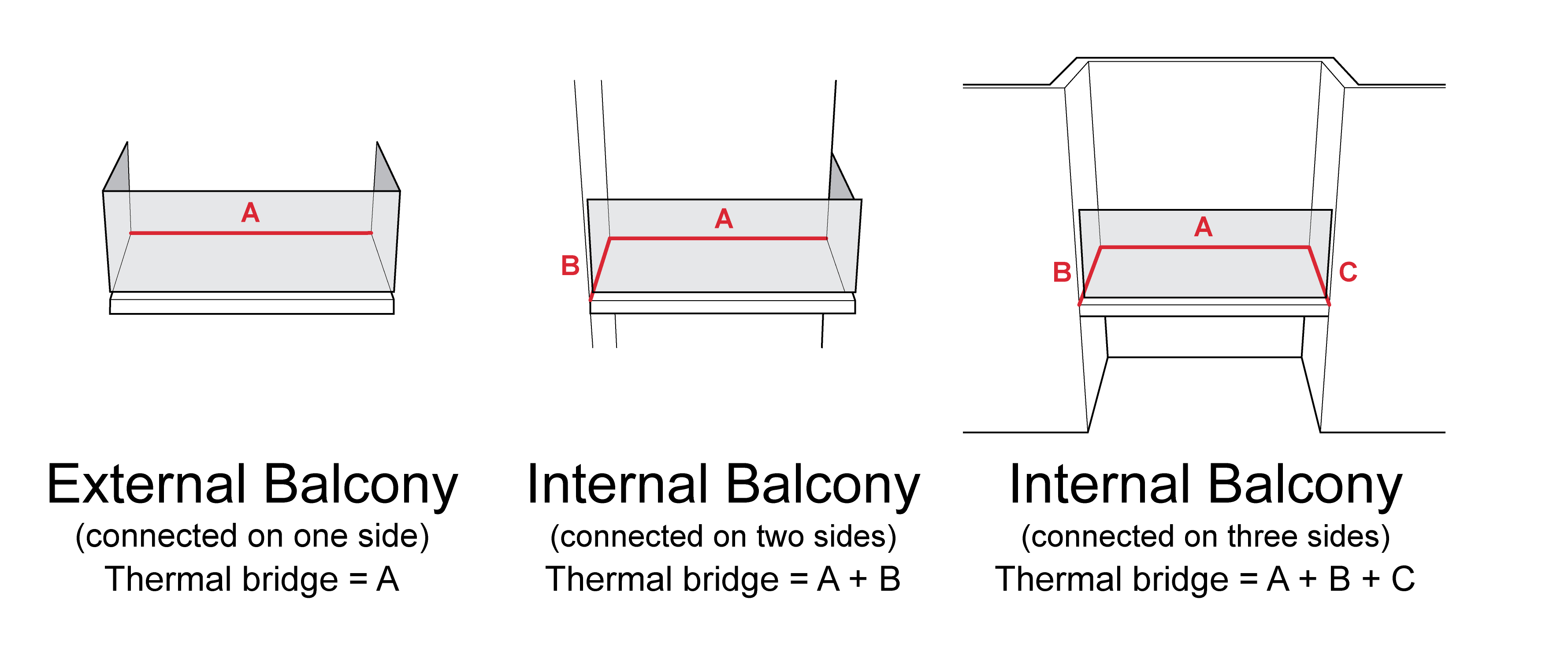
Balcony thermal bridging is influenced by balcony geometry – the greater the surface area of connection, the greater the thermal bridging (Figure 16). Note in Figure 16 that balcony thermal bridging can be reduced by reducing the connection surface area. An external balcony has less thermal bridging than an internal balcony. However, an internal balcony can be more easily constructed structurally with thermal breaks, using insulation products like those shown in Figure 25 and 26 below. External balconies are more difficult to construct with thermal breaks due to the structural load paths.
Thermal bridging between the balconies and the walls of a multistory building is a result of how much of the balcony touches the walls of the building
Thermal bridging between the balconies and the walls of a multistory building is a result of how much of the balcony touches the walls of the building
Figure 16. Thermal bridging between the balconies and the walls of a multistory building is a result of how much of the balcony touches the walls of the building (Source: Building Science Corporation).
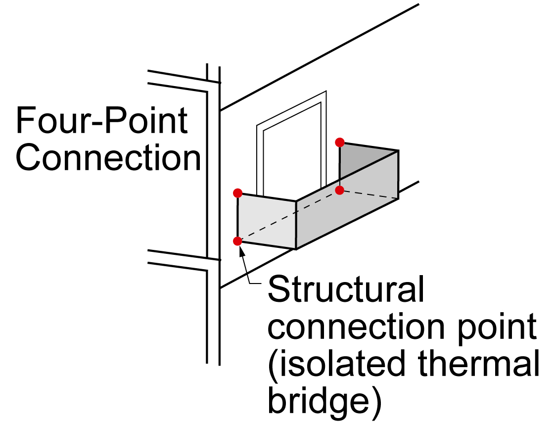
Figure 17 illustrates a “four-point connection” that addresses the structural load paths in an external balcony while minimizing thermal bridging.
This external balcony has a “four-point connection” – each red dot represents a structural connection point where the load from the balcony is carried to the building structure and where thermal bridging can occur
This external balcony has a “four-point connection” – each red dot represents a structural connection point where the load from the balcony is carried to the building structure and where thermal bridging can occur
Figure 17. This external balcony has a “four-point connection” – each red dot represents a structural connection point where the load from the balcony is carried to the building structure and where thermal bridging can occur (Source: Building Science Corporation).
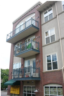
Figure 18 is a variation of a “four-point connection” – a discrete connection with suspension.
These balconies on a multistory multifamily building have “four-point connections” with thermal bridging only at the points where the edges of the balcony and railing attach to the wall
These balconies on a multistory multifamily building have “four-point connections” with thermal bridging only at the points where the edges of the balcony and railing attach to the wall
Figure 18. These external balconies on a multistory, multifamily building have “four-point connections” with thermal bridging only at the points where the edges of the balcony and balcony railing attach to the wall; the suspension wires carry much of the load (Source: Building Science Corporation).
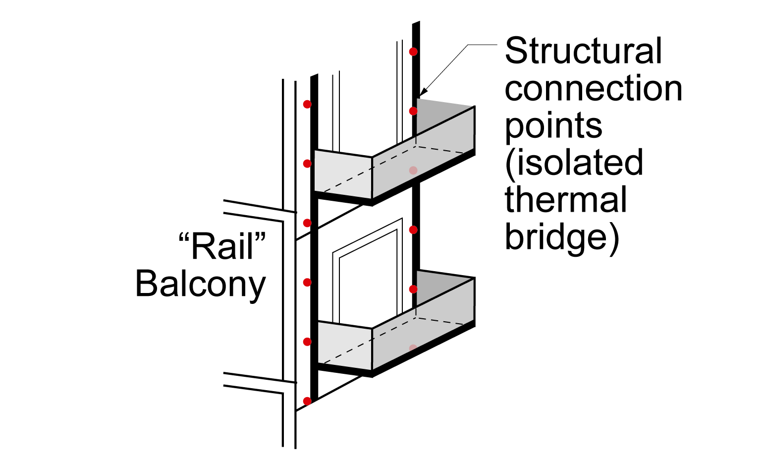
Figures 18 and 19 illustrate a “rail balcony connection” where the balcony is connected and supported by vertical rails that are “shimmed” or offset from the wall assembly by approximately 1 inch.
These balconies on a multistory, multifamily building have “rail” balcony connections where vertical rails attached to the building serve as the structural connection for the balconies to reduce thermal bridging through the exterior wall
These balconies on a multistory, multifamily building have “rail” balcony connections where vertical rails attached to the building serve as the structural connection for the balconies to reduce thermal bridging through the exterior wall
Figure 19. These external balconies on a multistory, multifamily building have “rail” balcony connections where vertical rails attached to the exterior of the building serve as the structural connection for the balconies to reduce thermal bridging through the exterior wall at each balcony (Source: Building Science Corporation).
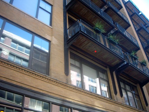
The vertical rails attached to the exterior of this multistory multifamily building are “rail” balcony connections providing structural connections for the balconies while avoiding thermal bridging through the exterior wall at each balcony
The vertical rails attached to the exterior of this multistory multifamily building are “rail” balcony connections providing structural connections for the balconies while avoiding thermal bridging through the exterior wall at each balcony
Figure 20. The vertical rails attached to the exterior of this multistory, multifamily building are “rail” balcony connections providing structural connections for the balconies while substantially reducing thermal bridging through the exterior wall at each balcony (Source: Building Science Corporation).
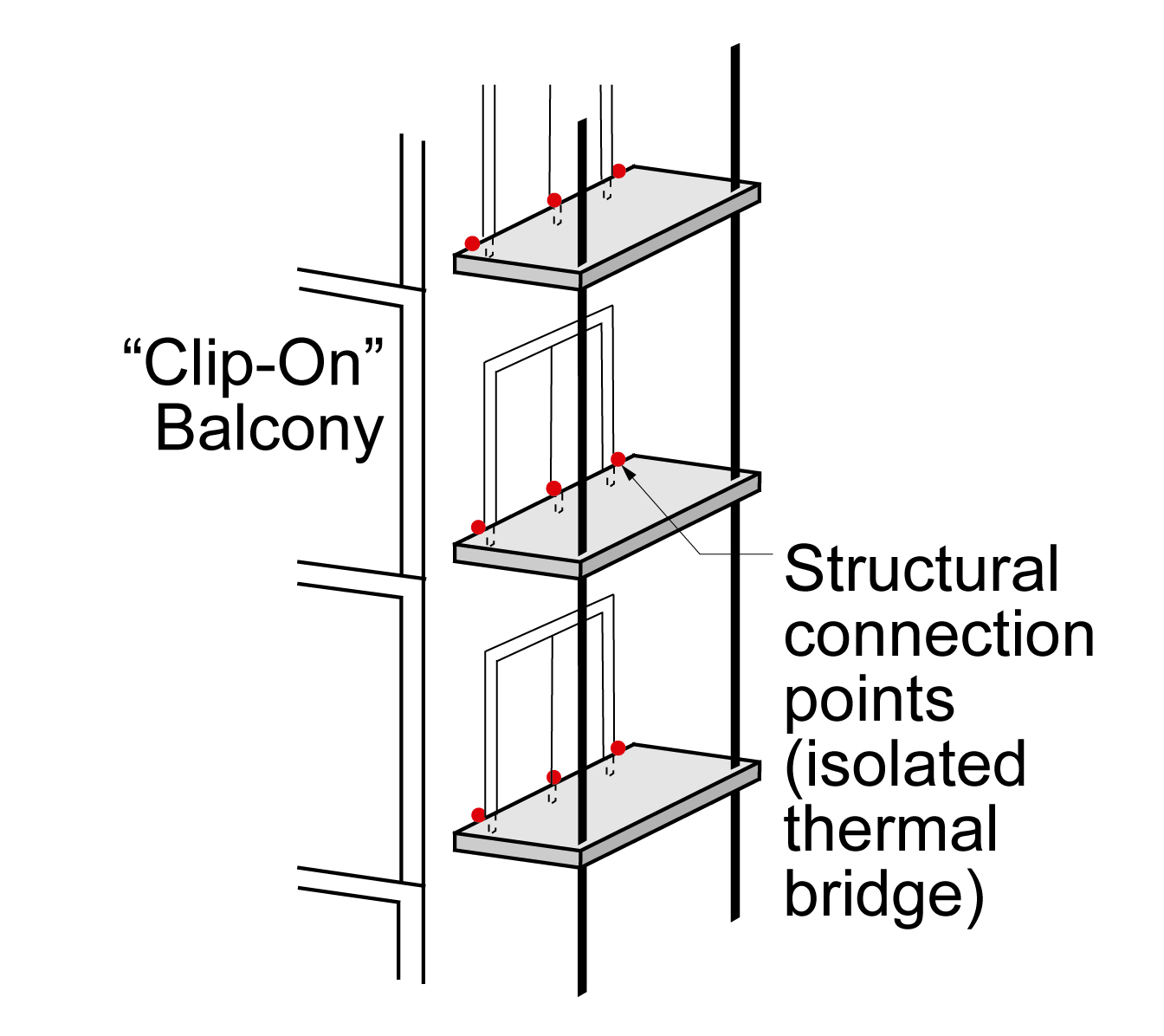
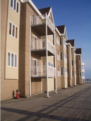
Figures 20 and 21 illustrate a “clip-on” balcony connection, which is a self-supported balcony.
These balconies on a multistory, multifamily building have “clip-on” balcony connections – the balconies attach to the exterior walls using clips with minimal thermal bridging; the structural load is primarily carried by external supporting pole
These balconies on a multistory, multifamily building have “clip-on” balcony connections – the balconies attach to the exterior walls using clips with minimal thermal bridging; the structural load is primarily carried by external supporting pole
Figure 21. These external balconies on a multistory, multifamily building have “clip-on” balcony connections – the balconies attach to the exterior walls using clips with minimal thermal bridging; the structural load is primarily carried by external supporting poles (Source: Building Science Corporation).
These balconies on a multistory multifamily building use “clip-on” connections to attach to the exterior walls with minimal thermal bridging; external poles carry most of the structural load
These balconies on a multistory multifamily building use “clip-on” connections to attach to the exterior walls with minimal thermal bridging; external poles carry most of the structural load
Figure 22. These external balconies on a multistory, multifamily building use “clip-on” connections to attach to the exterior walls with minimal thermal bridging; external poles carry most of the structural load (Source: Building Science Corporation).
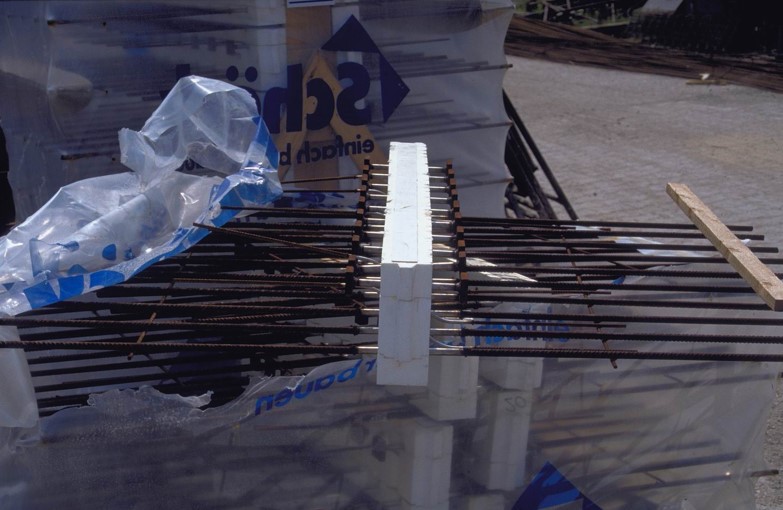
Figure 23 illustrates a continuous floor and balcony slab with intermittent concrete at the exterior wall. Stainless steel should be used for the rebar passing through the intermittent concrete connections. Stainless steel has one-third the conductivity of carbon steel. The key to the reduction in thermal conduction of this assembly is the reduction in the cross-sectional area of the concrete.
The slab floor in this multistory multifamily building is continuous, providing the interior floors and balcony floors; rigid foam placed in gaps in the slab at the exterior wall helps to reduce thermal bridging
The slab floor in this multistory multifamily building is continuous, providing the interior floors and balcony floors; rigid foam placed in gaps in the slab at the exterior wall helps to reduce thermal bridging
Figure 23. The slab floor of the external balcony in this multistory, multifamily building is continuous, providing both the interior floors and balcony floors; rigid foam placed in gaps in the slab at the exterior wall helps to reduce thermal bridging (Source: Building Science Corporation).
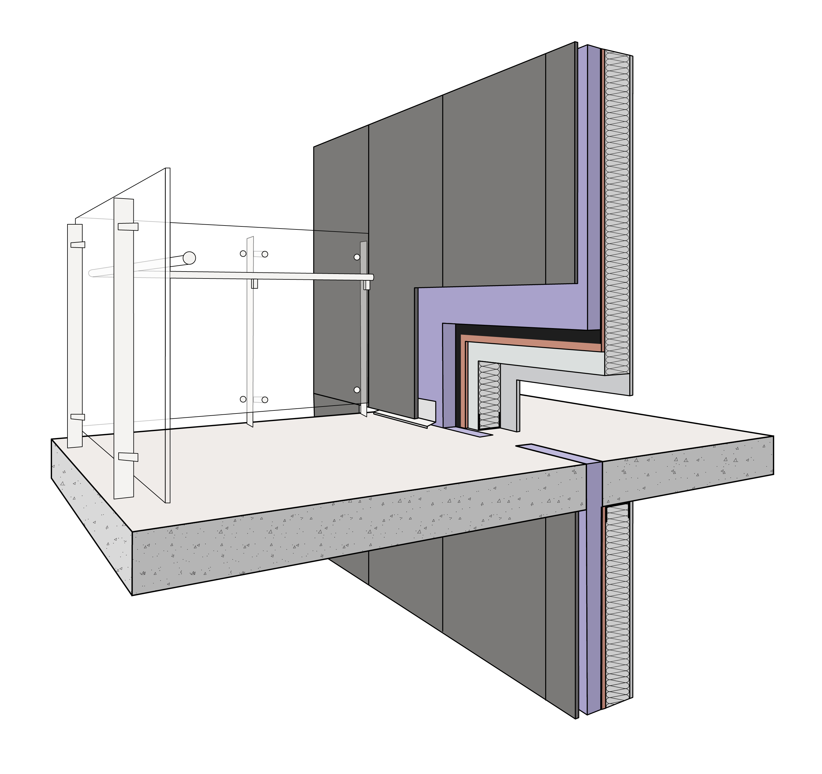
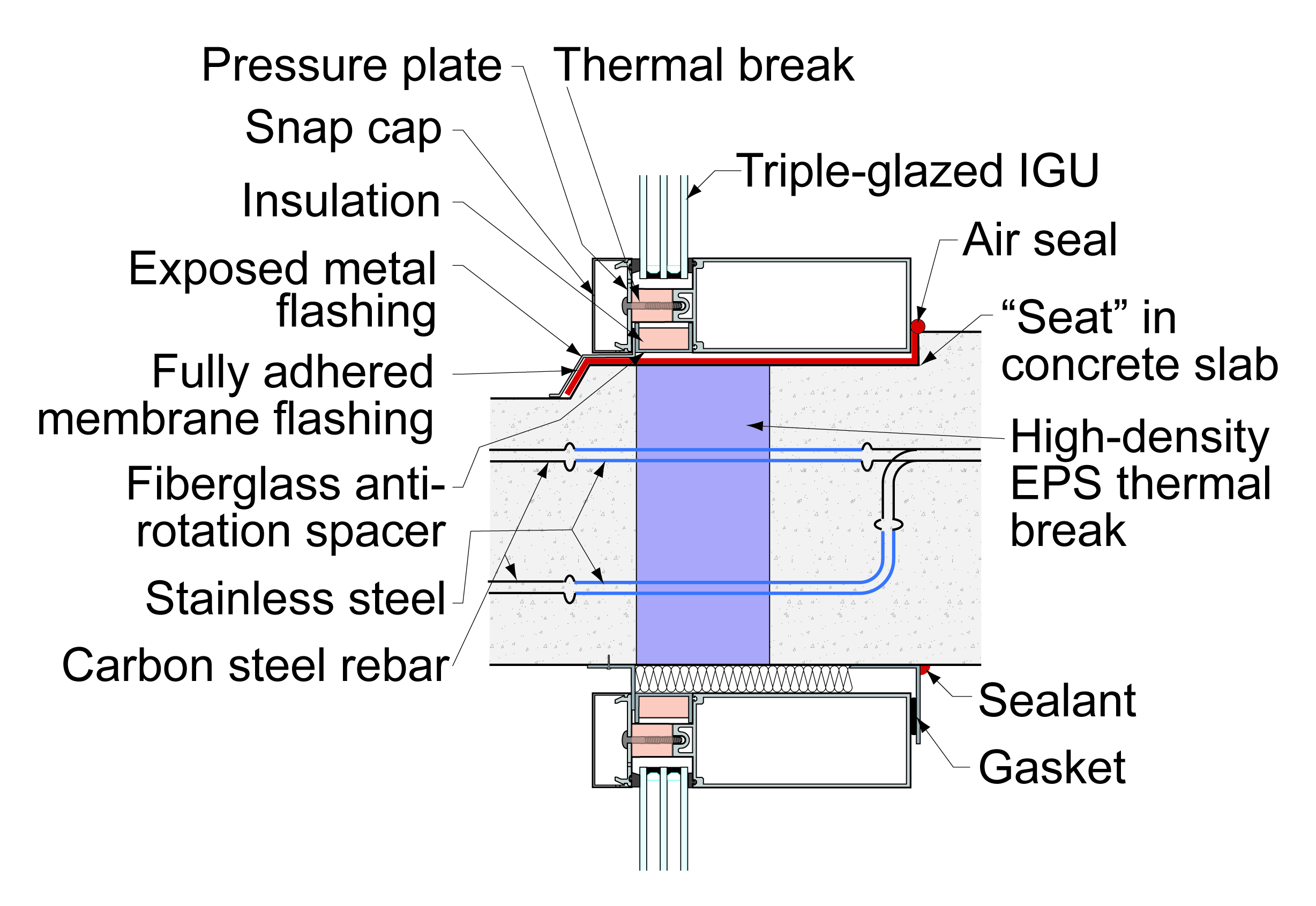
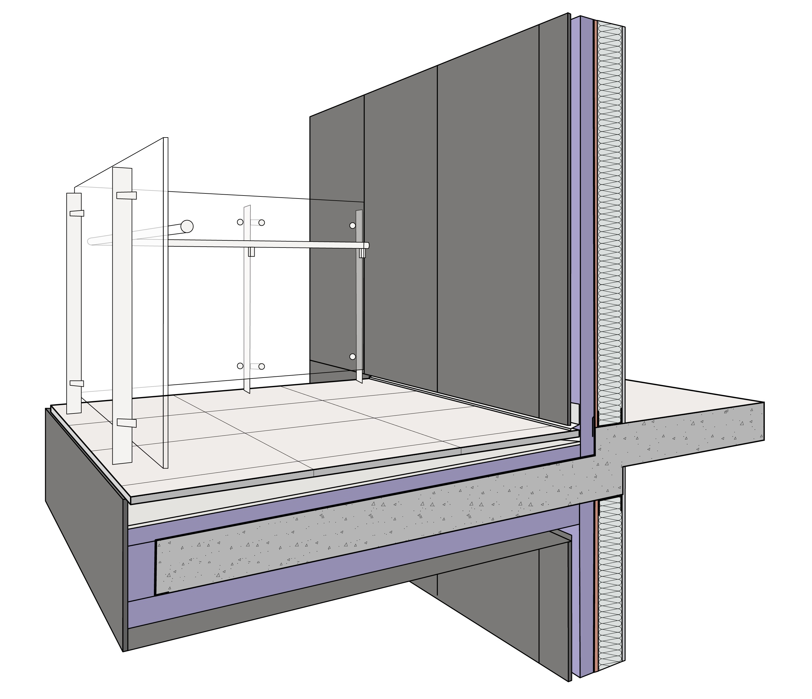
Figure 24 illustrates a continuous slab with a structural thermal break in the slab at the exterior wall which consists of glass curtain walls above and below the floor slab. Steel rebar provides structural support through the rigid foam that separates the interior floor slab from the exterior balcony slab. The portions of the rebar that pass through the rigid foam are stainless steel; the stainless-steel rods connect to carbon steel rebar in the concrete slab on each side of the break. Figure 25 illustrates the use of stainless-steel rebar at the structural thermal break to reduce thermal bridging. Figure 26 illustrates the use of a ceramic thermal break.
Rigid foam provides intermittent thermal breaks in a continuous slab floor with triple-pane-glass exterior wall panels in this multistory, multifamily building; stainless steel rebar provides structural support through the thermal break
Rigid foam provides intermittent thermal breaks in a continuous slab floor with triple-pane-glass exterior wall panels in this multistory, multifamily building; stainless steel rebar provides structural support through the thermal break
Figure 24. Rigid foam provides intermittent thermal breaks in a continuous slab floor with triple-pane-glass exterior wall panels in this multistory, multifamily building; stainless steel rebar provides structural support through the thermal break (Source: Building Science Corporation).
These prefabricated rebar assemblies use stainless steel and rigid foam to provide a thermal break where a concrete floor slab passes through the exterior wall of a multistory building; the stainless steel is connected to carbon steel rebar
These prefabricated rebar assemblies use stainless steel and rigid foam to provide a thermal break where a concrete floor slab passes through the exterior wall of a multistory building; the stainless steel is connected to carbon steel rebar
Figure 25. Prefabricated rebar assemblies like this use less conductive stainless steel and rigid foam to provide a thermal break where a concrete floor slab passes through the exterior wall of a multistory building; the stainless steel is connected to carbon steel rebar which provides the structural support in the floor and balcony slabs on either side of the wall (Source: Building Science Corporation).
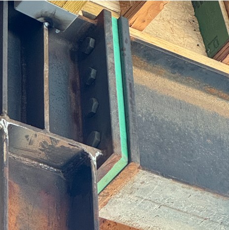
A ceramic panel provides the thermal break in the slab at the exterior wall of a multistory multifamily building; steel bolts provide structural support through the thermal break
A ceramic panel provides the thermal break in the slab at the exterior wall of a multistory multifamily building; steel bolts provide structural support through the thermal break
Figure 26. A ceramic panel provides the thermal break in the slab at the exterior wall of a multistory, multifamily building. Ceramic has very high compression strength; steel bolts provide structural support through the ceramic (Source: Building Science Corporation).
Figure 27 illustrates a continuous slab with wrapped insulation. This approach typically results in approximately a 50% reduction in thermal bridging. Note that the sides of the projecting balcony slab also need to be insulated and the finish decking on the balcony surface and the railings need to be structurally connected to the concrete balcony slab through the insulation layer Also note that the exterior portion of the slab is sloped down to ensure drainage away from the building. This approach typically results in approximately a 50% reduction in thermal bridging.
Rigid foam wraps this cantilevered balcony slab to provide a thermal break between the interior and exterior on this multifamily building
Rigid foam wraps this cantilevered balcony slab to provide a thermal break between the interior and exterior on this multifamily building
Figure 27. Rigid foam wraps this cantilevered balcony slab to provide a thermal break between the interior and exterior on this multistory, multifamily building (Source: Building Science Corporation).
Podium and Plazas
Where podium and plaza decks connect to or extend from building slabs that are part of conditioned spaces, thermal bridging can be significant. Figure 28 illustrates a significant thermal bridge location where conditioned occupied spaces or dwelling units are located above a first-floor slab over an unconditioned or partially conditioned garage that extends to create an outdoor podium or plaza (referred to in the rest of this section collectively as a plaza deck).
A significant thermal break occurs where the exterior wall connects to an unconditioned or partially conditioned garage with conditioned living spaces above
A significant thermal break occurs where the exterior wall connects to an unconditioned or partially conditioned garage with conditioned living spaces above
Figure 28. A significant thermal break occurs where the exterior wall of a multistory building connects to an unconditioned or partially conditioned garage with conditioned living spaces above (Source: Building Science Corporation).
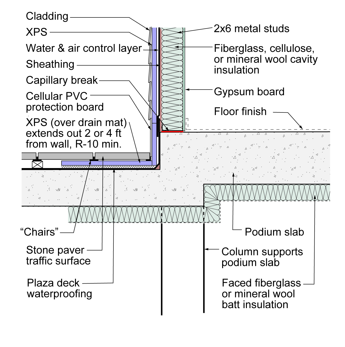
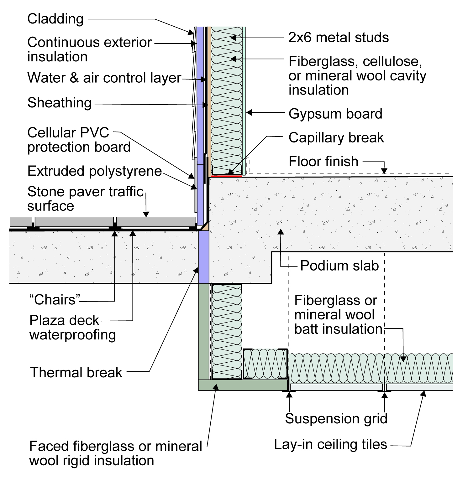
Figure 29 illustrates how the thermal bridging can be addressed by insulating both above and below the plaza deck where it extends outwards. The insulation above and below the plaza deck should extend out from the exterior wall a minimum of 2 to 4 feet depending on climate zone. The entire area of the slab under the conditioned space is insulated.
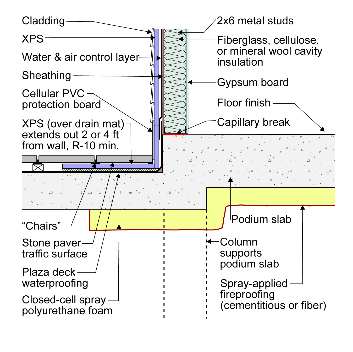
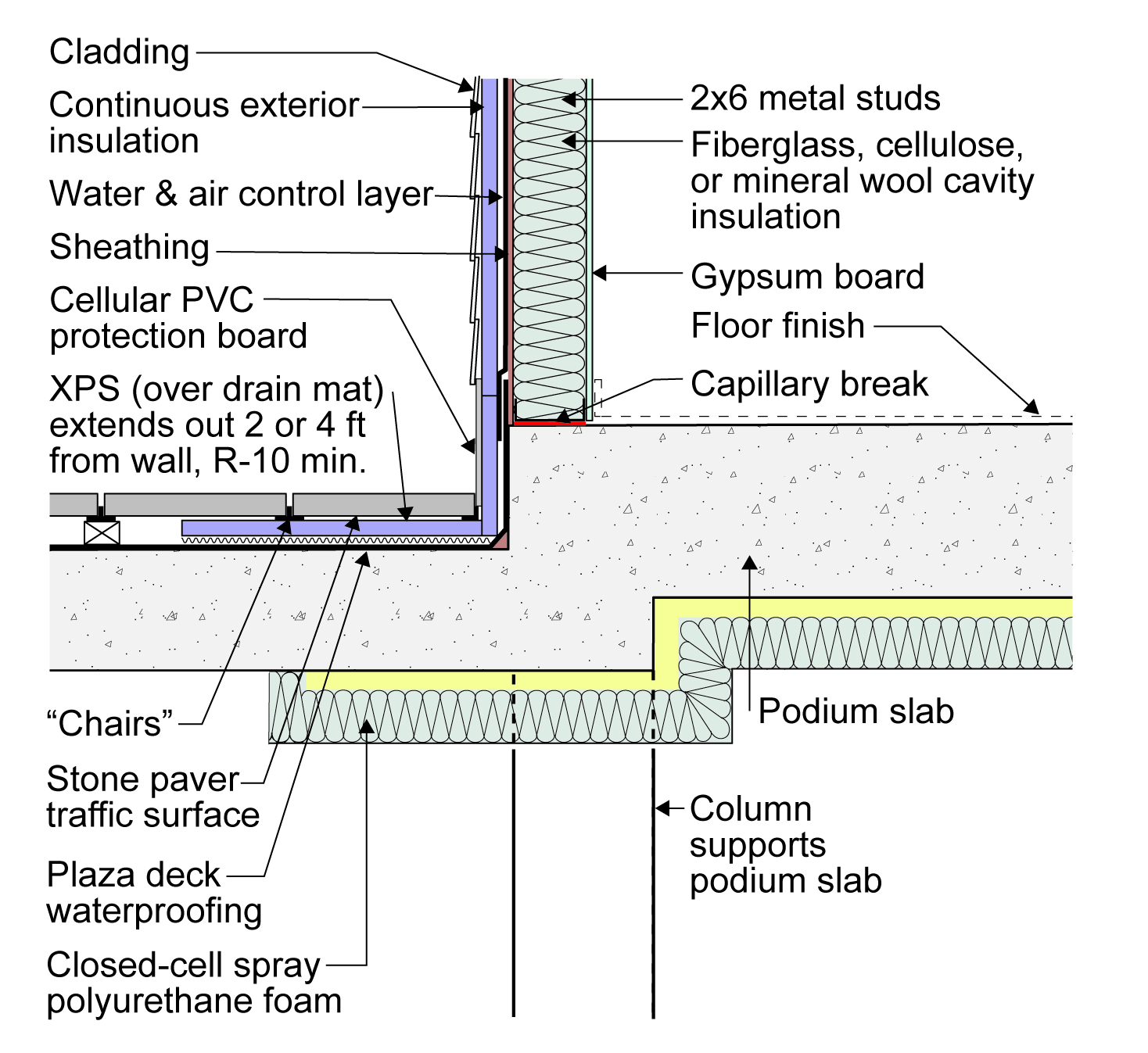
The insulation layer above the plaza deck insulation typically consists of extruded polystyrene over a drainage mat. The function of the drainage mat is to provide a capillary break between the waterproofing and the extruded polystyrene. The insulation under the plaza deck is often fiberglass or mineral wool batt insulation. However, it can be other insulation types such as closed-cell spray polyurethane foam with a fireproofing layer (Figure 30) or a hybrid assembly (Figure 31) of closed-cell spray polyurethane foam combined with fiberglass or mineral wool batt insulation to provide both thermal resistance and fireproofing.
Rigid insulation above and fibrous insulation below the projecting podium deck provide a thermal break between the outside and the unconditioned garage below and the conditioned living space above on the right in this multistory building
Rigid insulation above and fibrous insulation below the projecting podium deck provide a thermal break between the outside and the unconditioned garage below and the conditioned living space above on the right in this multistory building
Figure 29. Rigid insulation above and fibrous insulation below the projecting podium deck provide a thermal break between the outside and the unconditioned garage below and the conditioned living space above on the right in this multistory building (Source: Building Science Corporation).
Rigid insulation above and fibrous insulation below the projecting podium deck provide a thermal break between the outside, the unconditioned garage below, and the conditioned living space above on the right
Rigid insulation above and fibrous insulation below the projecting podium deck provide a thermal break between the outside, the unconditioned garage below, and the conditioned living space above on the right
Figure 30. Rigid insulation above and spray foam plus a spray-applied fireproofing below the projecting podium deck-exterior wall transition provide a thermal break between the outside and the unconditioned garage below and the conditioned living space above on the right in this multistory building (Source: Building Science Corporation).
Rigid insulation above and spray foam plus fibrous insulation below the projecting podium deck provide a thermal break between the outside and the unconditioned garage below and the conditioned living space above on the right in this building
Rigid insulation above and spray foam plus fibrous insulation below the projecting podium deck provide a thermal break between the outside and the unconditioned garage below and the conditioned living space above on the right in this building
Figure 31. Rigid insulation above and spray foam plus fibrous insulation below the projecting podium deck provide a thermal break between the outside and the unconditioned garage below and the conditioned living space above on the right in this multistory building (Source: Building Science Corporation).
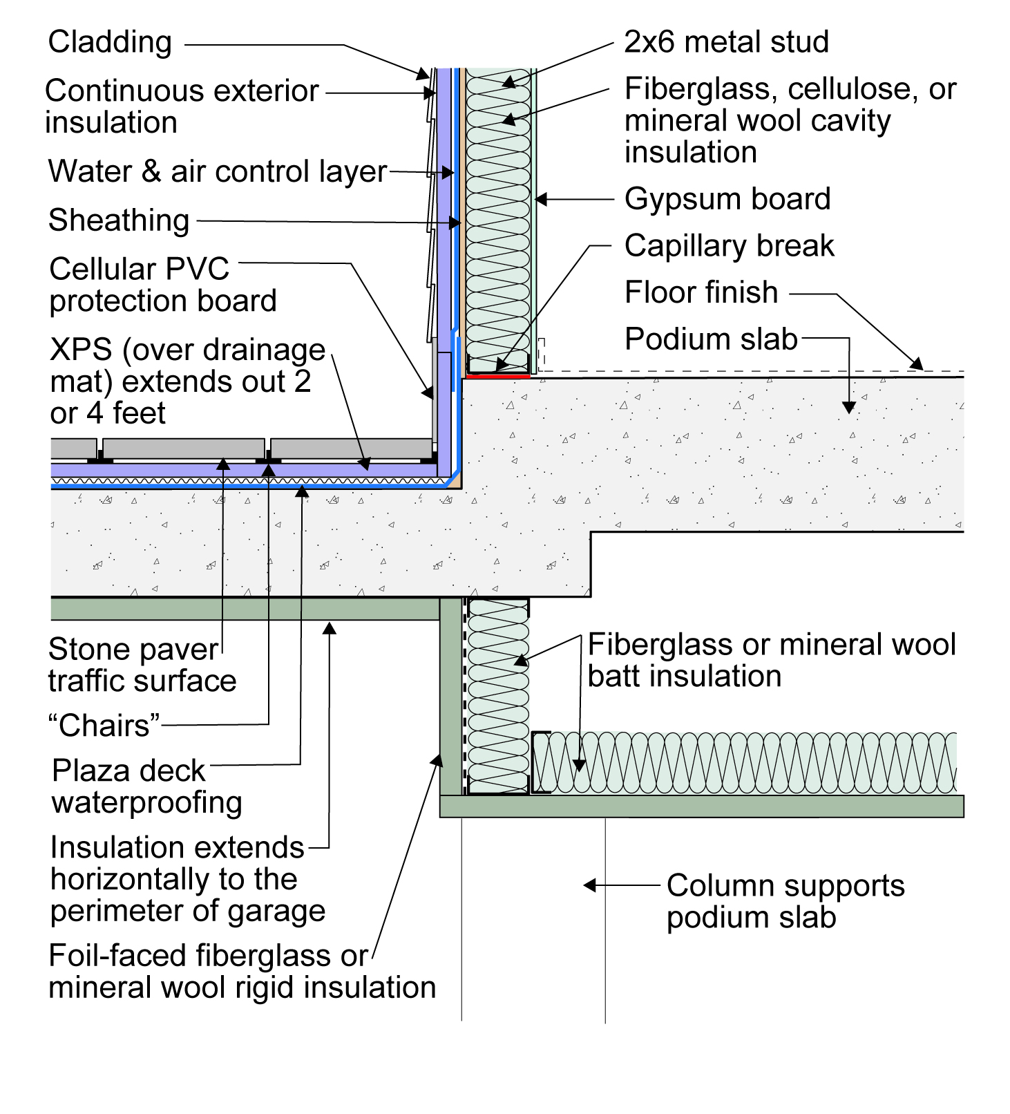
Figure 32 shows where a dropped-ceiling, insulated, conditioned plenum is used to insulate the portion of the slab under the conditioned spaces and minimize the thermal bridging of the plaza deck portion of the slab.
Rigid insulation above and below the projecting podium deck and insulation below the conditioned plenum under the first floor provide a thermal break between the outside, unconditioned garage, and conditioned living space above and to the right
Rigid insulation above and below the projecting podium deck and insulation below the conditioned plenum under the first floor provide a thermal break between the outside, unconditioned garage, and conditioned living space above and to the right
Figure 32. Rigid insulation above and below the projecting podium deck and rigid insulation plus fibrous insulation below the conditioned plenum under the first floor of a multistory building provide a thermal break between the outside and the unconditioned garage and the conditioned living space above and to the right (Source: Building Science Corporation).
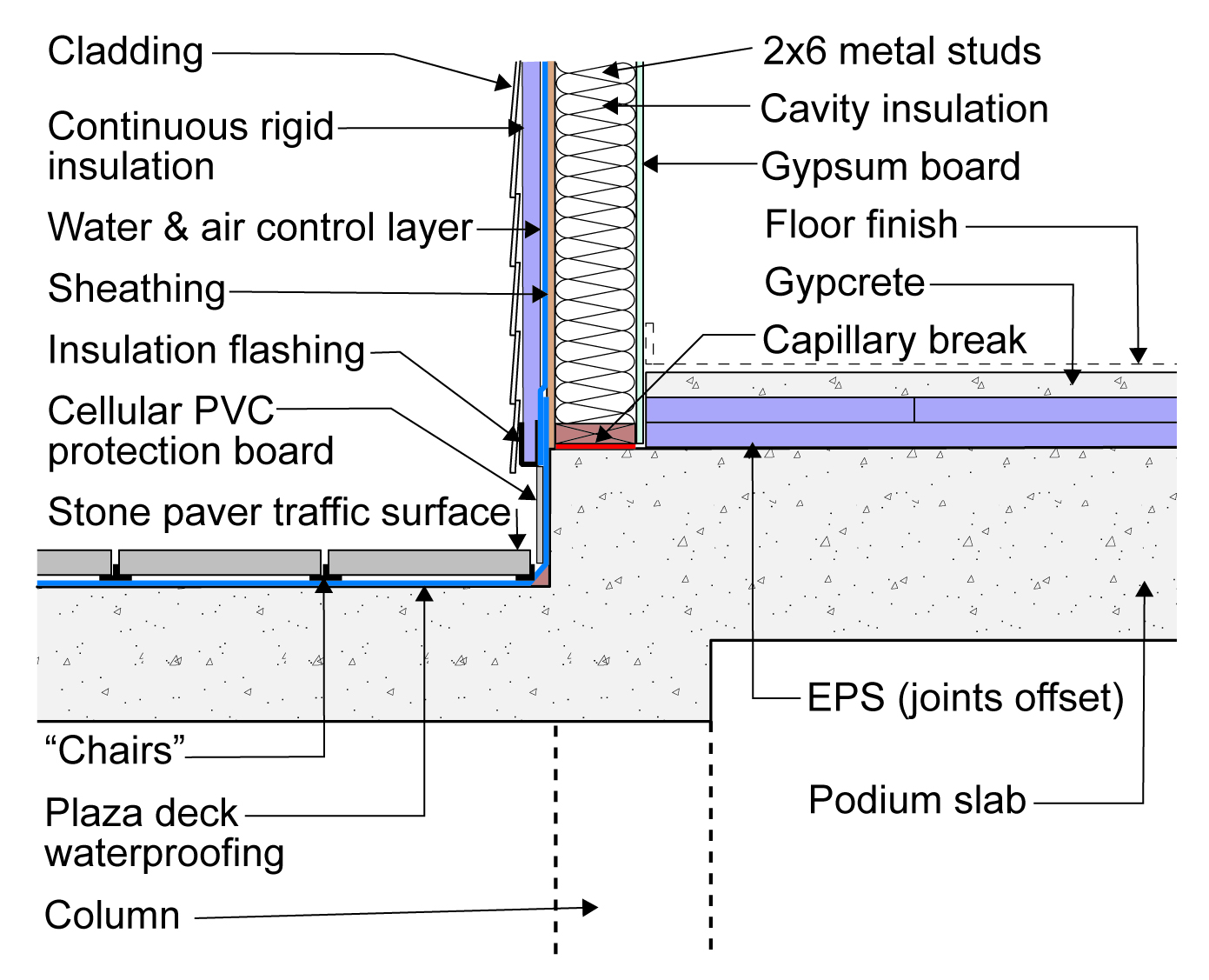
Figure 33 shows the use of rigid insulation as a thermal break between two separately cast slabs that are independently supported by columns.
Rigid insulation provides a thermal break at the projecting podium deck; the plaza deck and podium slab are independently supported by structural columns in this building. A dropped ceiling plenum above the garage gives space for floor insulation
Rigid insulation provides a thermal break at the projecting podium deck; the plaza deck and podium slab are independently supported by structural columns in this building. A dropped ceiling plenum above the garage gives space for floor insulation
Figure 33. Rigid insulation provides a thermal break at the projecting podium deck; the plaza deck and podium slab are independently supported by structural columns in this multistory building. A dropped ceiling plenum above the garage provides space for floor insulation (Source: Building Science Corporation).
Figure 34 shows the use of rigid insulation installed on top of the conditioned portion of the podium slab. This may be the simplest and cheapest option for some builders.
The living space in this multistory, multifamily building is thermally insulated from the outside and the unconditioned garage below by insulating above the podium slab
The living space in this multistory, multifamily building is thermally insulated from the outside and the unconditioned garage below by insulating above the podium slab
Figure 34. The living space in this multistory, multifamily building is thermally insulated from the outside and the unconditioned garage below by insulating above the podium slab (Source: Building Science Corporation).
Slab Edge Insulation
Where concrete slabs intersect concrete foundation stem walls at building exteriors, the concrete slab should be thermally isolated, i.e., thermally uncoupled or “thermally broken” from the concrete stem foundation wall. Figures 34 and 35 illustrate two approaches for insulating the slab in a slab-on-grade foundation with stem wall. The approach shown in Figure 36, with insulation extending down the stem wall, should be used in colder climates (IECC climate zones 5 and higher). In Figures 34-40, the subslab gravel could be replaced with foam glass gravel. This product is made from recycled glass, has high compressive strength and drainage properties, and provides an R value of about R-1.7 per inch. Combined insulation R-values should be per local code requirements.
The concrete slab is thermally isolated from the concrete foundation stem wall
The concrete slab is thermally isolated from the concrete foundation stem wall
Figure 36. The concrete slab is thermally isolated from the concrete foundation stem wall and the stem wall is insulated for cold climates (Source: Building Science Corporation).
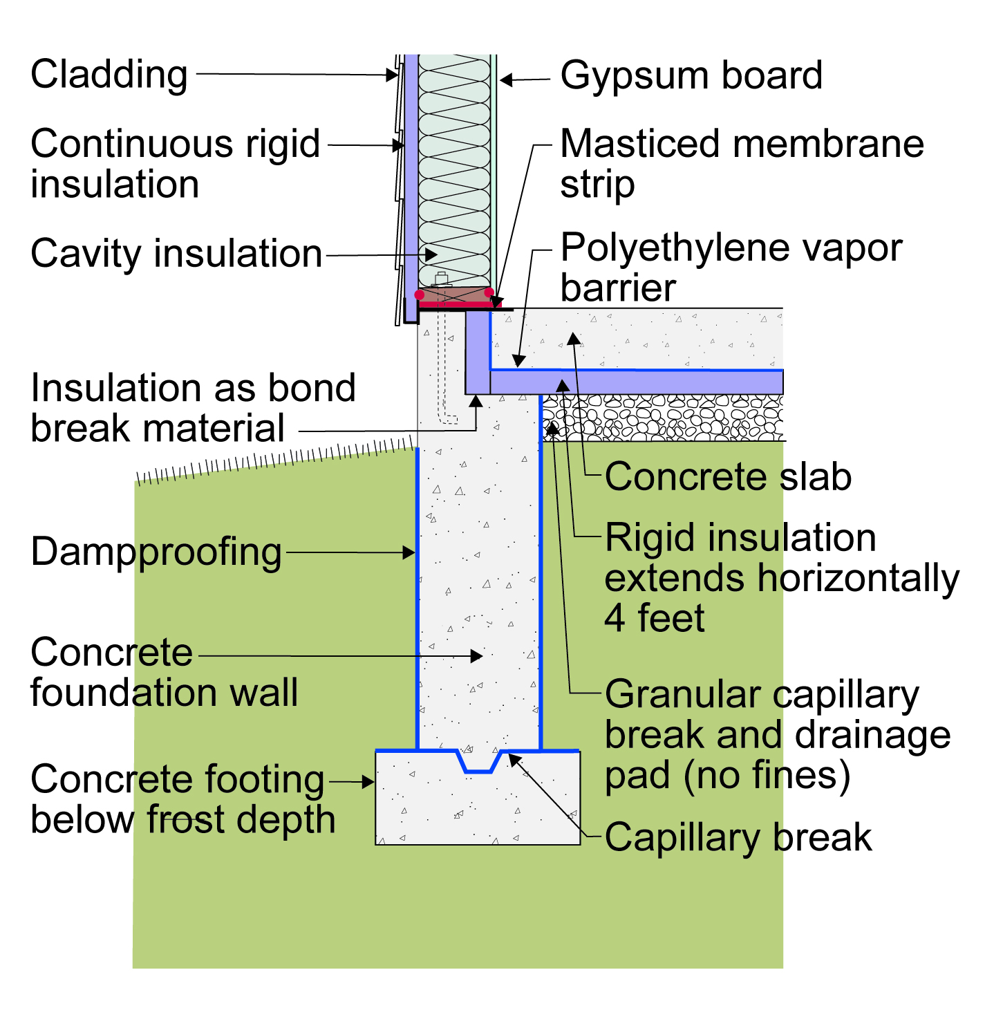
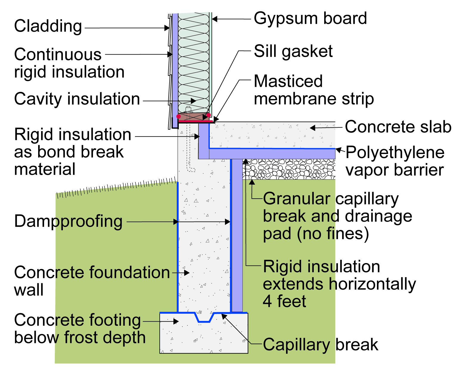
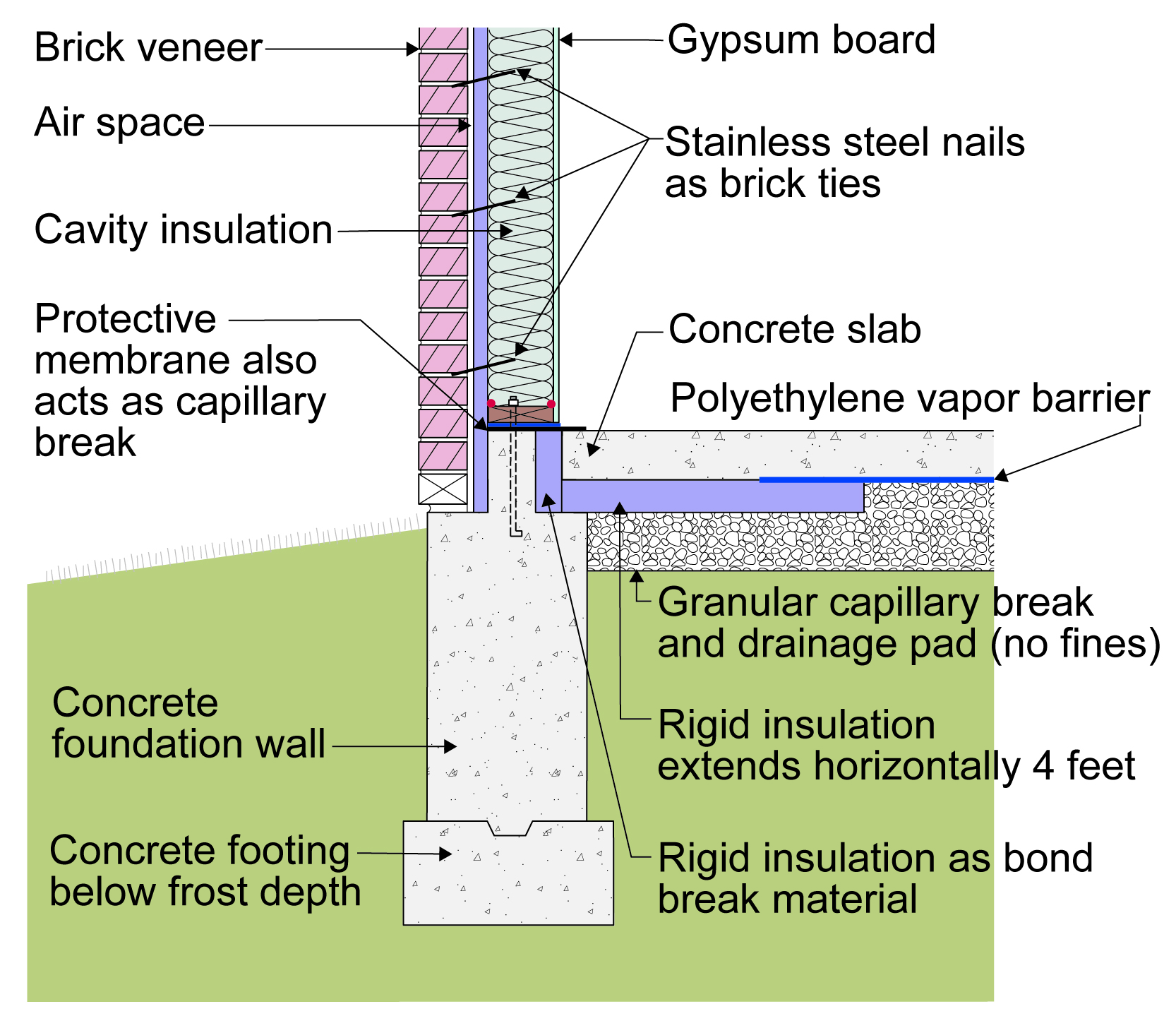
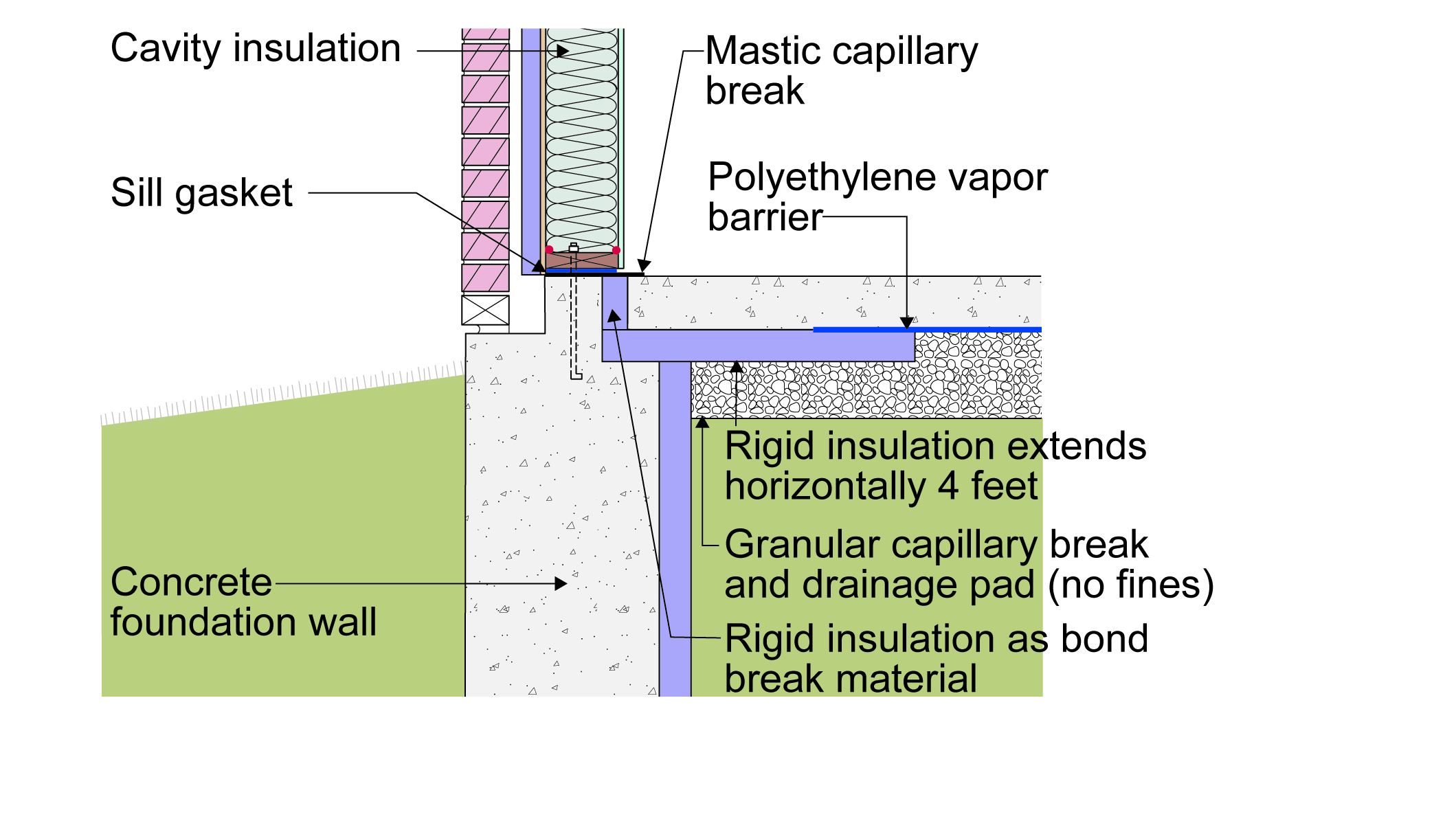
Figure 37 and Figure 38 illustrate two approaches where brick veneer claddings are installed. The concrete foundation stem wall will need to be at least 10 inches thick in order to provide sufficient bearing for the brick veneer (2.5 inches) plus a 1-inch drainage cavity behind the brick veneer and a minimum bearing of 3.5 inches for the 2x6 frame wall. The exterior continuous rigid insulation is assumed to be 1 inch thick; the sub-slab insulation is assumed to be 2 inches thick. Figure 38 with the insulated stem wall is more applicable in colder climates – IECC Climate Zones 5 and higher.
Rigid foam is installed behind the brick veneer and at the slab edge and perimeter to thermally isolate the concrete floor slab from the stem wall
Rigid foam is installed behind the brick veneer and at the slab edge and perimeter to thermally isolate the concrete floor slab from the stem wall
Figure 37. Rigid foam is installed behind the brick veneer and at the slab edge and perimeter to thermally isolate the concrete floor slab from the stem wall (Source: Building Science Corporation).
Rigid foam is installed behind the brick veneer, at the slab edge and perimeter, and down the interior of the stem wall to thermally isolate the concrete floor slab from the stem wall
Rigid foam is installed behind the brick veneer, at the slab edge and perimeter, and down the interior of the stem wall to thermally isolate the concrete floor slab from the stem wall
Figure 38. Rigid foam is installed behind the brick veneer, at the slab edge and perimeter, and down the interior of the stem wall to thermally isolate the concrete floor slab from the stem wall (Source: Building Science Corporation).
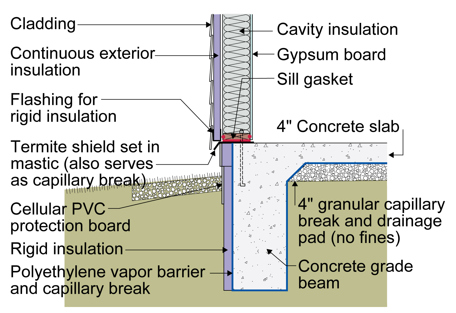
Figure 39 illustrates a monolithic concrete slab on grade that is insulated on the exterior. Note the termite shield and the removable strip of insulation to allow for termite inspections in areas known for termite infestation or as required by local code. This wall is shown with clapboard siding, PVC facers at grade, and metal channel for rodent protection at the bottom of the exterior insulation.
A monolithic concrete slab is insulated on the exterior slab edge with rigid foam
A monolithic concrete slab is insulated on the exterior slab edge with rigid foam
Figure 39. A monolithic concrete slab is insulated on the exterior slab edge with rigid foam (Source: Building Science Corporation).
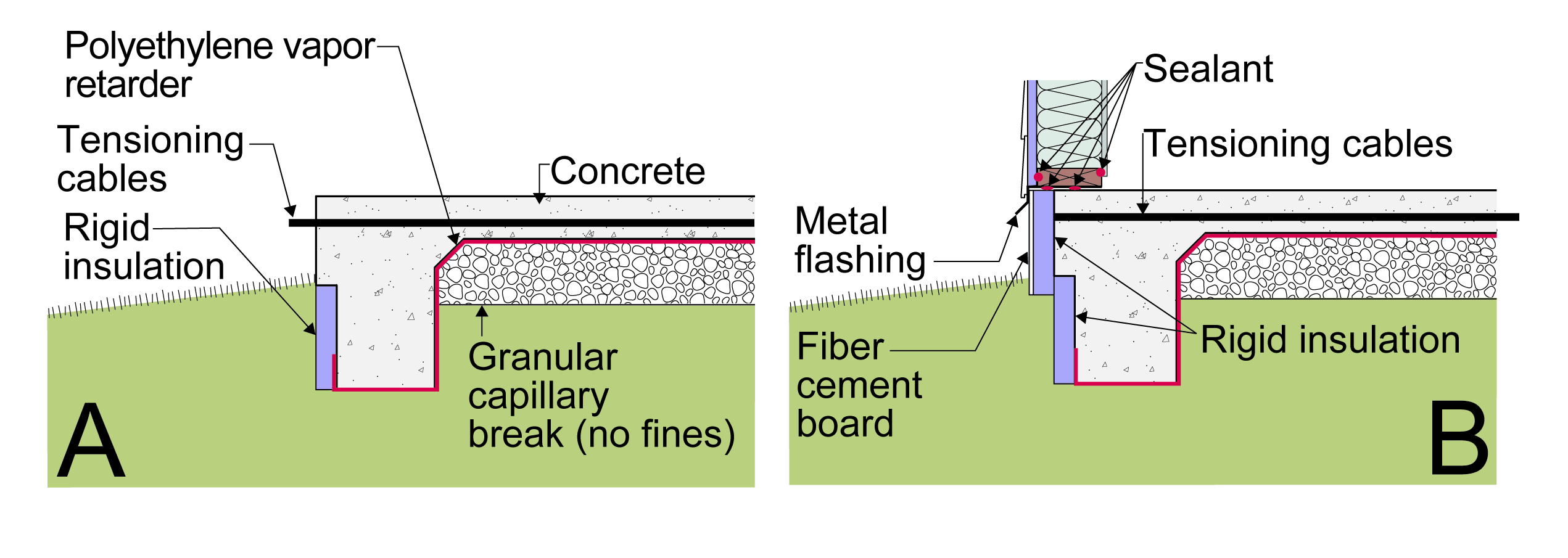
Figure 40 illustrates how post-tensioned monolithic slabs can be insulated on the exterior slab edge. Figure 40a illustrates the first step...installing an insulated strip below the location where post-tensioning occurs. The insulated strip is placed in the forms prior to the placing of the concrete. After the slab is post-tensioned, Figure 40b illustrates the installation of a second layer of insulation and protection board.
Insulate a post-tensioned monolithic concrete slab: A) Install rigid foam in form before pouring concrete for slab, B) After concrete cures, install a second layer of rigid foam and protection board on the exterior perimeter of the wall
Insulate a post-tensioned monolithic concrete slab: A) Install rigid foam in form before pouring concrete for slab, B) After concrete cures, install a second layer of rigid foam and protection board on the exterior perimeter of the wall
Figure 40. Insulate a post-tensioned monolithic concrete slab: A) Install rigid foam in form before pouring concrete for slab, B) After concrete cures, install a second layer of rigid foam and protection board on the exterior perimeter of the wall (Source: Building Science Corporation ).
Figure 41 illustrates another approach to insulating monolithic concrete slabs where the rigid insulation is installed above the slab. Note, weep openings are included with an open vertical joint between every other brick.
Insulate a monolithic concrete slab above the slab with rigid foam
Insulate a monolithic concrete slab above the slab with rigid foam
Figure 41. Insulate a monolithic concrete slab above the slab with rigid foam (Source: Building Science Corporation).
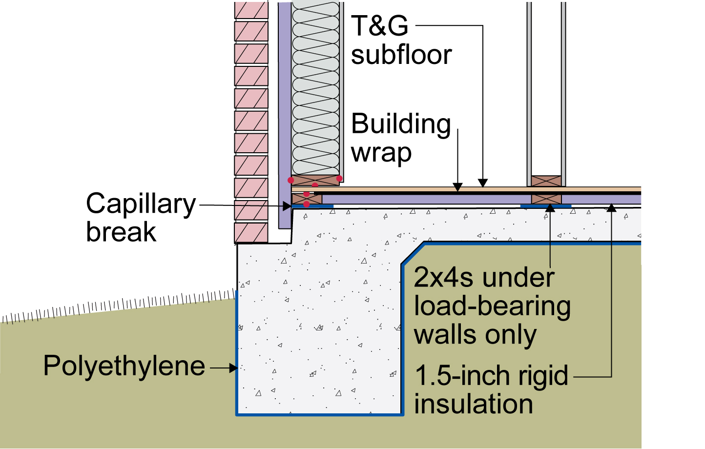
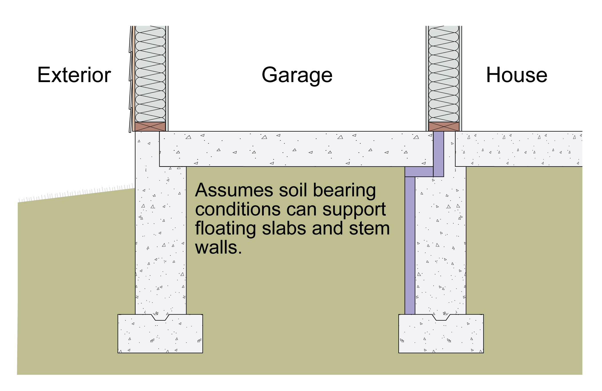
Figure 42 illustrates the installation of a thermal break along the stem wall between a garage slab and the slab under the conditioned space of the home. As with all of these drawings, insulation amounts are based on local code requirements.
The slab edge of this floating slab and the stem wall are insulated to thermally separate the conditioned living space from the garage
The slab edge of this floating slab and the stem wall are insulated to thermally separate the conditioned living space from the garage
Figure 42. The slab edge of this floating slab and the stem wall are insulated to thermally separate the conditioned living space from the garage (Source: Building Science Corporation).
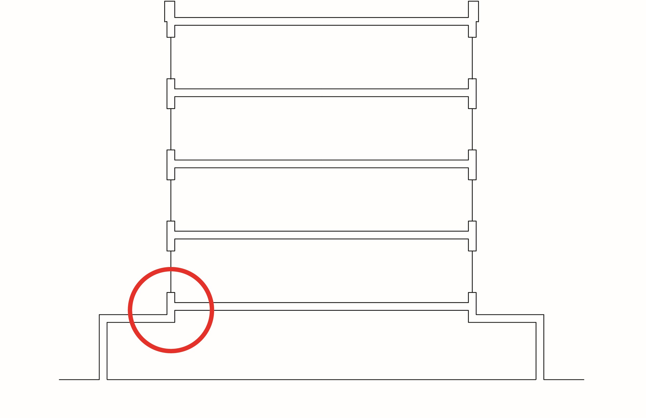
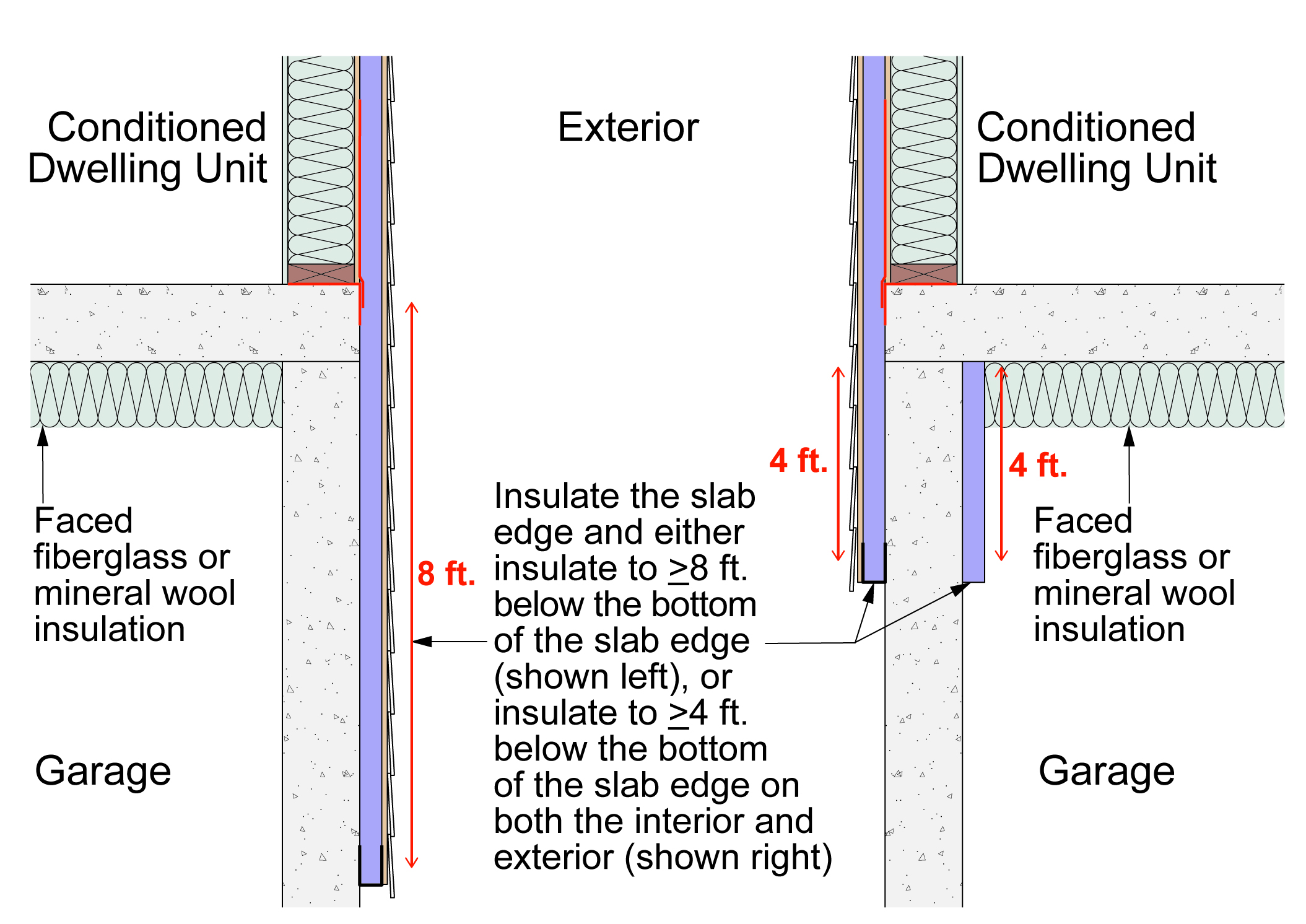
Figure 43 illustrates two approaches for insulating concrete slab edges where the slab is constructed over an unconditioned space such as a garage and is supported by a concrete wall.
Insulate slab edge where concrete floor slab over unconditioned space is supported by a wall by either insulating along the full length of the wall and 8 feet down from the slab edge or on both the exterior and interior 4 feet down from slab edge
Insulate slab edge where concrete floor slab over unconditioned space is supported by a wall by either insulating along the full length of the wall and 8 feet down from the slab edge or on both the exterior and interior 4 feet down from slab edge
Figure 43. Insulate the slab edge where the concrete floor slab over unconditioned space is supported by an exterior concrete wall by either insulating along the full length of the exterior wall and 8 feet down from the slab edge or by insulating on both the exterior and interior 4 feet down from the slab edge (Source: Building Science Corporation).
Insulated Concrete Form (ICF) Systems
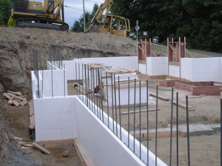
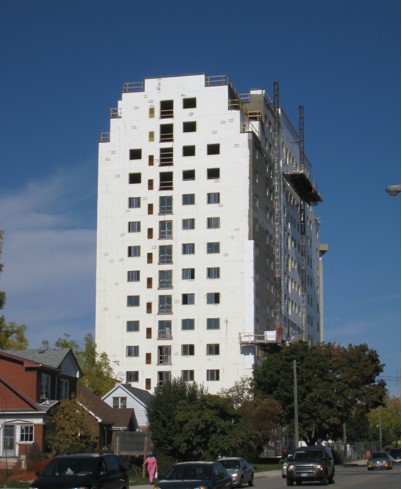
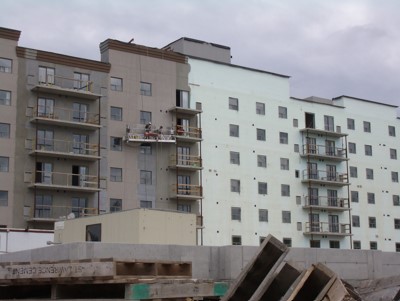
Insulated concrete forms (ICFs) are hollow blocks made of sheets of rigid foam. The blocks are stacked like bricks to form hollow walls that are reinforced with rebar then filled with poured concrete. The rigid foam remains in place permanently to provide insulation for the structure (Figure 44). They are used in single-family construction as well as in multistory, multifamily construction (Figure 45). The exterior cladding system for ICF systems is typically direct-applied synthetic stucco (Figure 46). For more on ICF construction, see the guide Insulated Concrete Forms (ICFs).
Insulated concrete forms (ICF) are hollow blocks made of sheets of rigid foam that are stacked like bricks then filled with poured concrete to create insulated concrete walls for homes and buildings
Insulated concrete forms (ICF) are hollow blocks made of sheets of rigid foam that are stacked like bricks then filled with poured concrete to create insulated concrete walls for homes and buildings
Figure 44. Insulated concrete forms (ICF) are hollow blocks made of sheets of rigid foam that are stacked like bricks then filled with poured concrete to create insulated concrete walls for homes and buildings (Source: Building Science Corporation).
This 14-story multifamily building was constructed with insulated concrete forms (ICFs)
This 14-story multifamily building was constructed with insulated concrete forms (ICFs)
Figure 46. This multistory, multifamily building was constructed of insulated concrete forms (ICFs); synthetic stucco can be applied directly over the ICF (Source: Building Science Corporation).
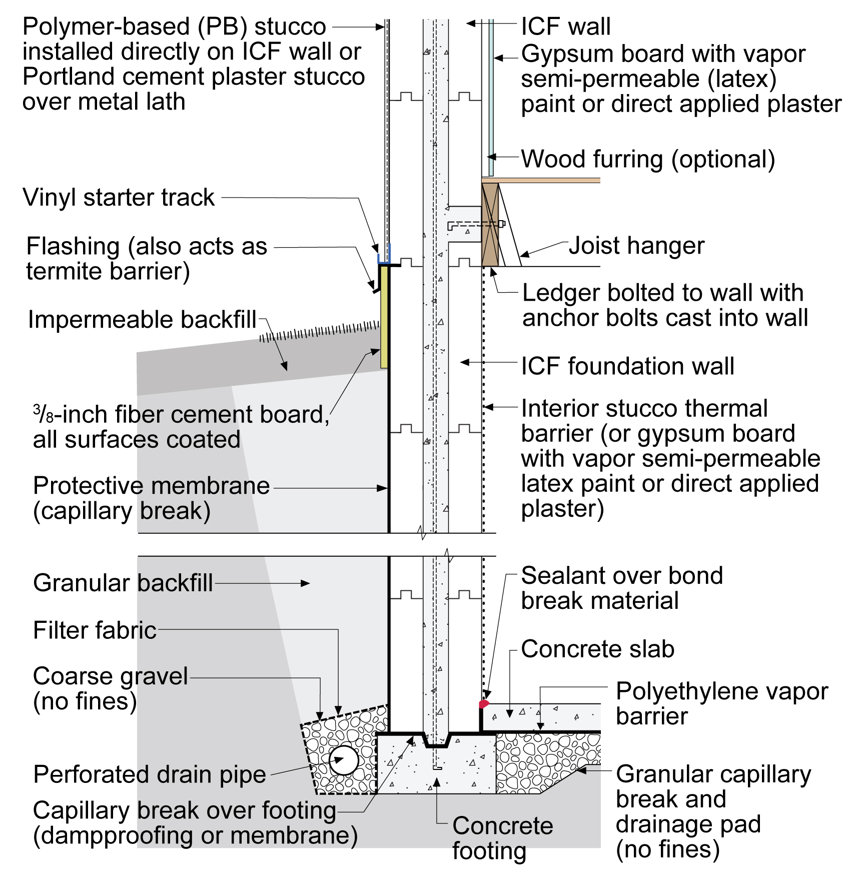
In multi-story ICF construction, the concrete floor slabs are supported by the reinforced concrete core of the ICFs (Figure 47). The ICFs can extend below grade where they provide a foundation wall that is insulated on both the exterior and interior (Figure 48). Exterior below-grade protection is provided by a protective membrane that acts as a capillary break. Control of exterior hydrostatic pressure is provided by installing draining granular backfill or dimpled plastic drainage mats (not shown) directly against the exterior of the protective membrane to encourage drainage down to the perimeter foundation drain pipe at the base of the foundations, shown in Figure 48.
In multistory insulating concrete form (ICF) buildings, the concrete floor slabs are integrated into the ICF exterior walls and structurally supported by the reinforced concrete wall cores
In multistory insulating concrete form (ICF) buildings, the concrete floor slabs are integrated into the ICF exterior walls and structurally supported by the reinforced concrete wall cores
Figure 47. In multis tory insulating concrete form (ICF) buildings, the concrete floor slabs are integrated into the ICF exterior walls and structurally supported by the reinforced concrete wall cores (Source: Building Science Corporation).
In multistory insulating concrete form (ICF) buildings, the concrete floor slabs are integrated into the ICF exterior walls and structurally supported by the reinforced concrete wall cores
In multistory insulating concrete form (ICF) buildings, the concrete floor slabs are integrated into the ICF exterior walls and structurally supported by the reinforced concrete wall cores
Figure 48. Insulated concrete forms (ICF) provide an insulated below-grade foundation wall; the floor is connected to the ICF wall with joist hangers and ledger bolted into the concrete core of the ICF (Source: Building Science Corporation).
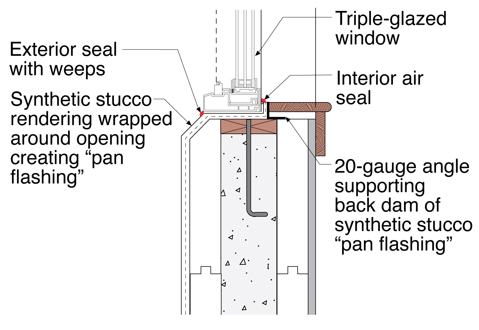
Window openings are water-proofed by extending the synthetic stucco into the opening on all sides of the window (head, jambs, and sill) (Figure 49).
Synthetic stucco wraps all four sides of the window openings and creates a pan flashing on the sills in exterior walls created from insulated concrete forms (ICF)
Synthetic stucco wraps all four sides of the window openings and creates a pan flashing on the sills in exterior walls created from insulated concrete forms (ICF)
Figure 49. Synthetic stucco wraps all four sides of the window openings and creates a pan flashing on the sills in exterior walls created from insulated concrete forms (ICF) (Source: Building Science Corporation).
Ensuring Success
The building design details should be reviewed for thermal performance – specifically thermal bridging. Unique details should be modeled using three-dimensional finite element heat transfer modeling (THERM) to verify performance. Unique details should be “mocked up” to verify constructability.
Region
The design and installation approaches are climate independent – they work in all climates to reduce the effect of thermal bridging. Be sure to specify at least the minimum insulation R-value as required for your climate zone by the International Energy Conservation code.
Training
Right and Wrong Images
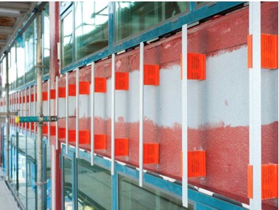
Right - Stainless steel screws, which are less conductive than other types of steel, are used to attach the “double” hat channels that hold the exterior insulation in place behind the cladding on this multistory multifamily building
Right - Stainless steel screws, which are less conductive than other types of steel, are used to attach the “double” hat channels that hold the exterior insulation in place behind the cladding on this multistory multifamily building
Right – Fiberglass connectors provide a thermal break between the metal cladding attachment and the wall assembly on this multistory multifamily building
Right – Fiberglass connectors provide a thermal break between the metal cladding attachment and the wall assembly on this multistory multifamily building
American Society of Heating Refrigerating and Air-Conditioning Engineers
Description
Technical report describing the thermal performance of 40 common building envelope details for mid- and high-rise buildings, including analyses to optimize energy efficiency and reduce thermal bridging.
Guide describing methodologies for assessing and mitigating thermal bridging in building envelopes, featuring detailed performance data, interface solutions, and assembly-specific strategies for energy-efficient construction.
Technical report describing the impact of thermal bridging in balcony connections, presenting alternative design strategies, performance analyses, and case studies to enhance energy efficiency and reduce carbon emissions in building envelopes.
Technical report describing design and construction methodologies for durable balconies and decks, focusing on proper sloping, flashing, drainage, and ventilation to mitigate moisture-related issues.
Article describing thermal bridging, construction practices that encourage thermal bridging, and solving thermal bridging through continuous exterior insulation.
This content is a work created with funding provided by the United States Department of Energy under Contract no DE-AC05-076RL01830 for the operation of Pacific Northwest National Laboratory. The information and guidance provided by Pacific Northwest National Laboratory (PNNL) in the content are intended solely for educational purposes only and do not constitute formal training or certification. It is provided with the explicit understanding that neither the United States Government nor the United States Department of Energy, nor the Contractor, nor any or their employees, nor any jurisdiction or organization that has cooperated in the development of these materials, makes any warranty, express or implied, or assumes any legal liability or responsibility for the accuracy, completeness, or usefulness or any information, apparatus, product, software, or process disclosed, or represents that its use would not infringe privately owned rights. Reference herein to any specific commercial product, process, or service by trade name, trademark, manufacturer, or otherwise does not constitute or imply its endorsement, recommendation, or favoring by the United States Government or any agency thereof, or Battelle Memorial Institute. The views and opinions of authors expressed herein do not necessarily state or reflect those of the United States Government or any agency thereof. Viewers assumes full responsibility for all actions that they may take from information provided in this content including ensuring the safety, code compliance, and proper functionality of any products they choose to install. Installation and use of such products should be performed in accordance with local regulations and manufacturer instructions.