

Scope
Insulate a new foundation wall or an existing foundation wall by adding rigid insulation to the exterior side as follows:
- Locate underground utilities.
- Excavate the foundation perimeter.
- Install a footing perimeter drain pipe to provide adequate exterior drainage.
- Install damp proofing or a waterproofing membrane on the exterior side of the foundation wall and footing
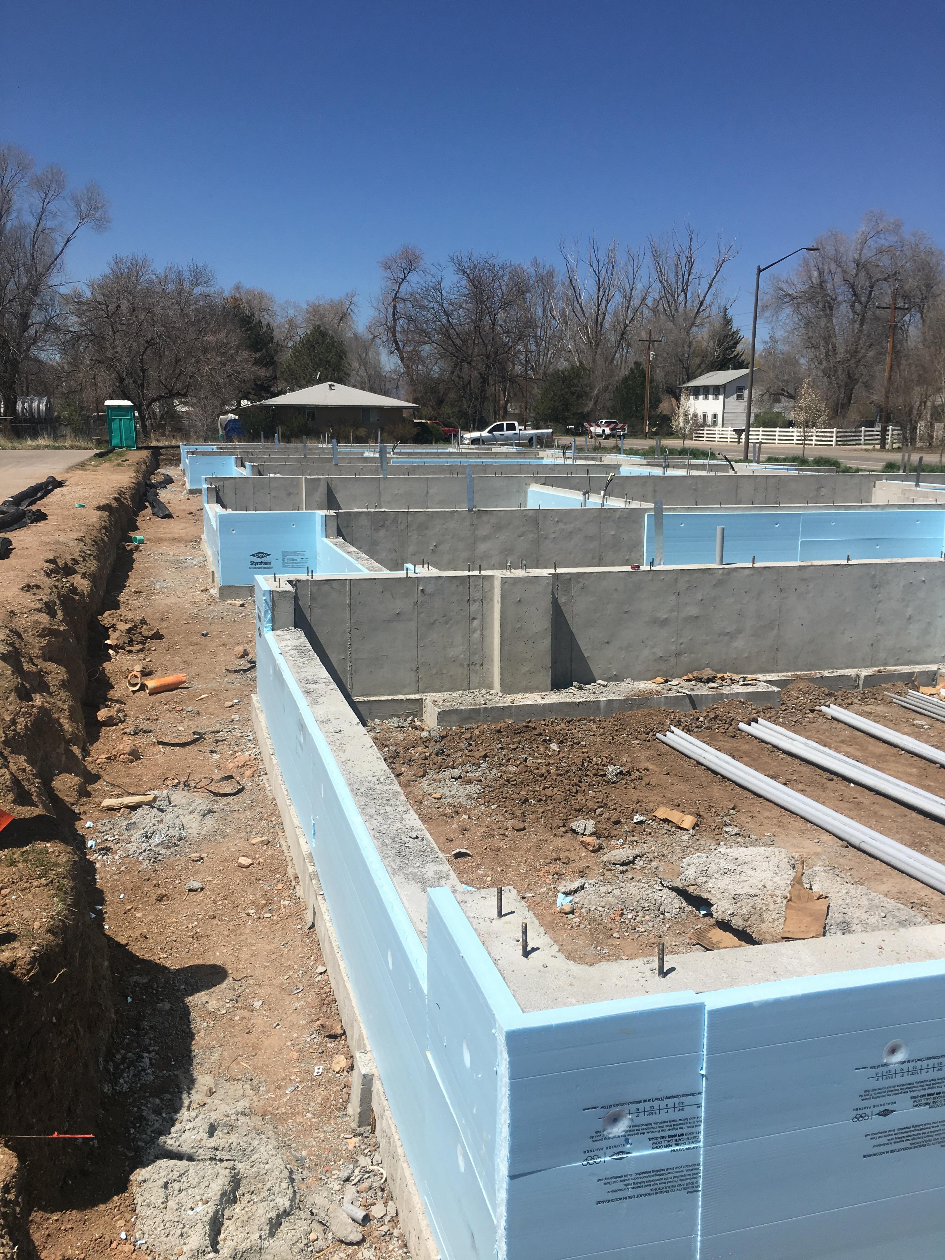
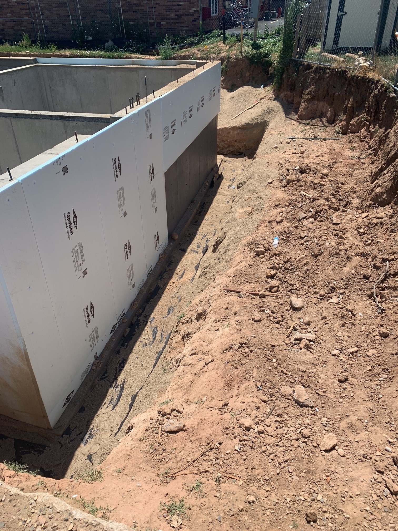
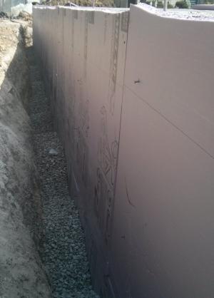
- Install rigid board insulation (such as XPS, foil-faced polyisocyanurate, or rigid mineral fiber) on the exterior wall from the top of the footing to the bottom of the cladding to at least the minimum R-value specified in the local building code.
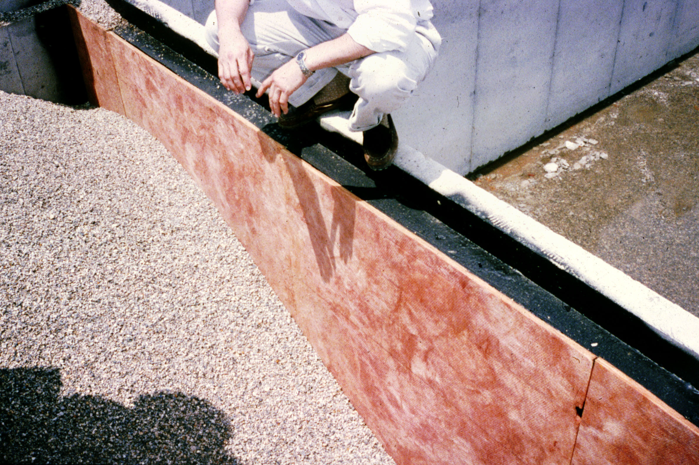
- Install an aluminum coil stock or sheet metal protective cover for the rigid insulating sheathing.
- Back-fill excavation to within 8 inches of the finished grade with free-draining backfill.
- Install closed-cell sprayed polyurethane foam (SPF) insulation on the interior side of the rim joist.
Note that this assembly is appropriate only for flat foundation walls. Due to the cost and logistical difficulties, this measure is typically more suitable for new construction rather than a retrofit project.
See the Compliance Tab for links to related codes and standards and voluntary federal energy-efficiency program requirements.
Description
Rigid board insulation (such as XPS, foil-faced polyisocyanurate, or rigid mineral fiber) can be installed on the exterior side of homes with smooth foundation walls such as those made of cast concrete or concrete block. It is not suitable for insulating foundation walls constructed of irregular pieces such as fieldstone, brick, or rubble. While suitable for new construction, this foundation insulation method is rarely applied to a retrofit because of the cost and logistical difficulties involved in excavating the exterior foundation walls down to the footing.
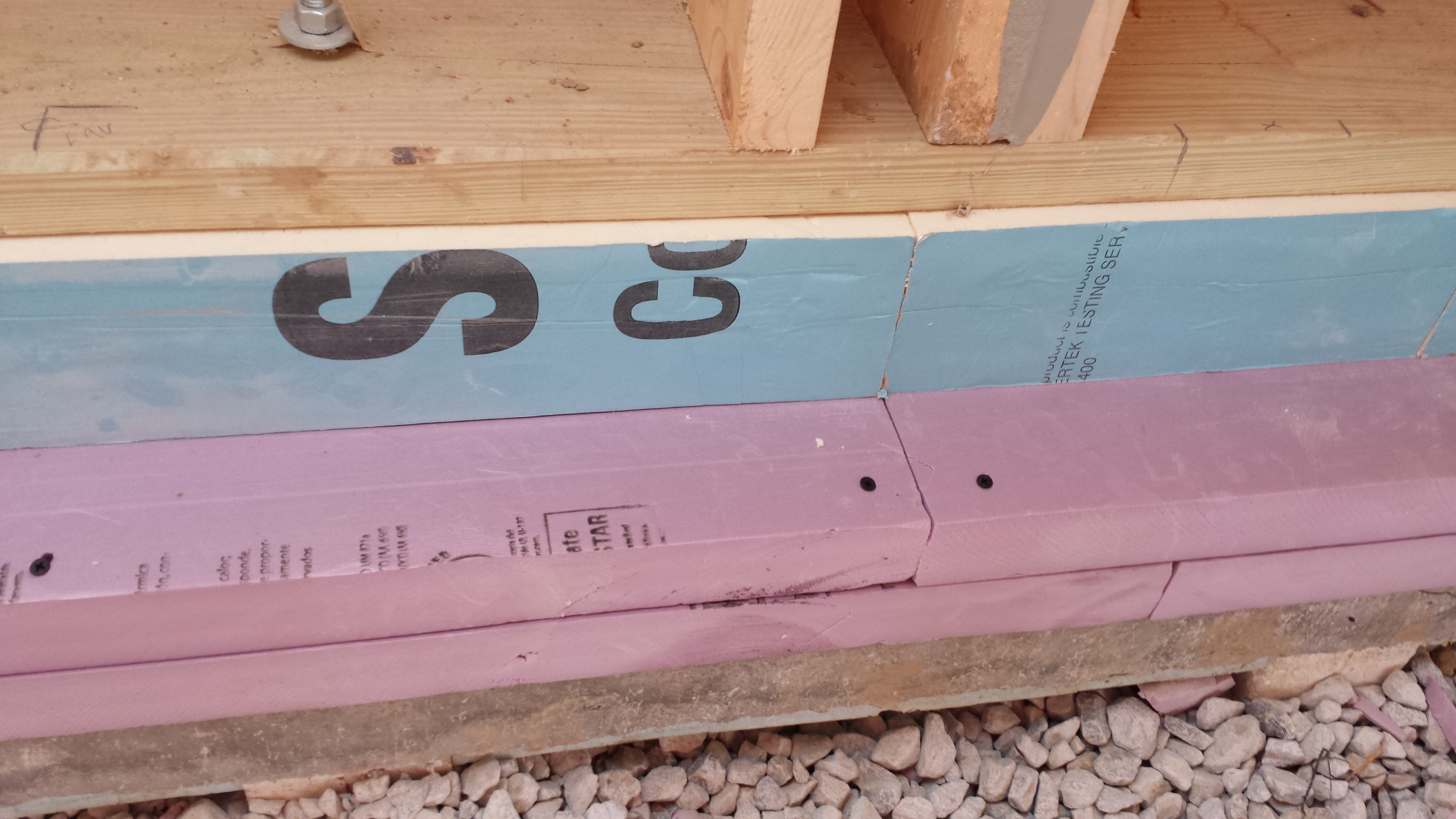
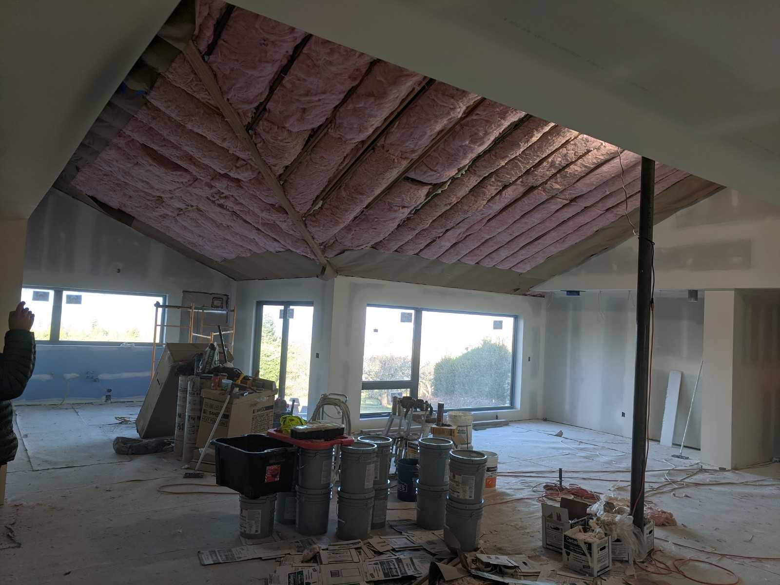
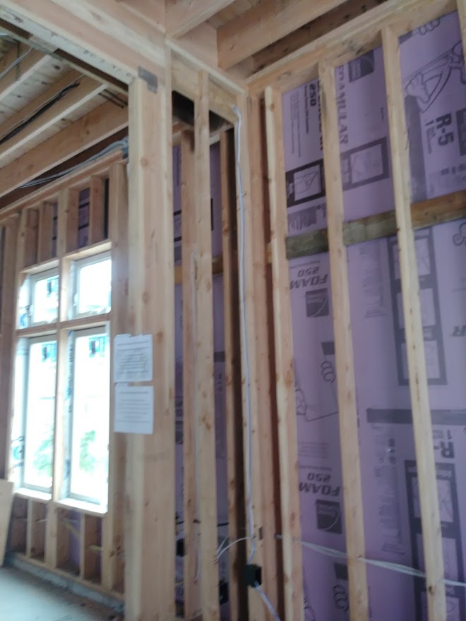
The rim joist can be insulated on the interior with sprayed polyurethane foam (SPF) insulation applied from inside the basement or crawlspace. The spray foam should cover the sill plate and extend from the top of the foundation wall to the underside of the subfloor to provide continuity of the thermal control layer at the transition between the rigid insulation below grade and the cavity insulation above grade.
In retrofit cases, an assessment should be made of the condition of the sill prior to beginning the retrofit. If there is no capillary break under the sill and/or if the sill is within 12 inches of the ground, it is possible that it has suffered water damage. If so, the damaged pieces should be replaced and at the same time, a capillary break should be installed under the new pieces. If there is no capillary break under the sill and /or the sill is within 12 inches of the ground but there is no indication of damage, then it is likely that the sill has been able to dry. Depending on the properties of the exterior rigid insulation and waterproofing, the new assembly may have limited drying potential to the exterior, and if so, care must be taken to preserve the drying potential of the assembly to the interior.
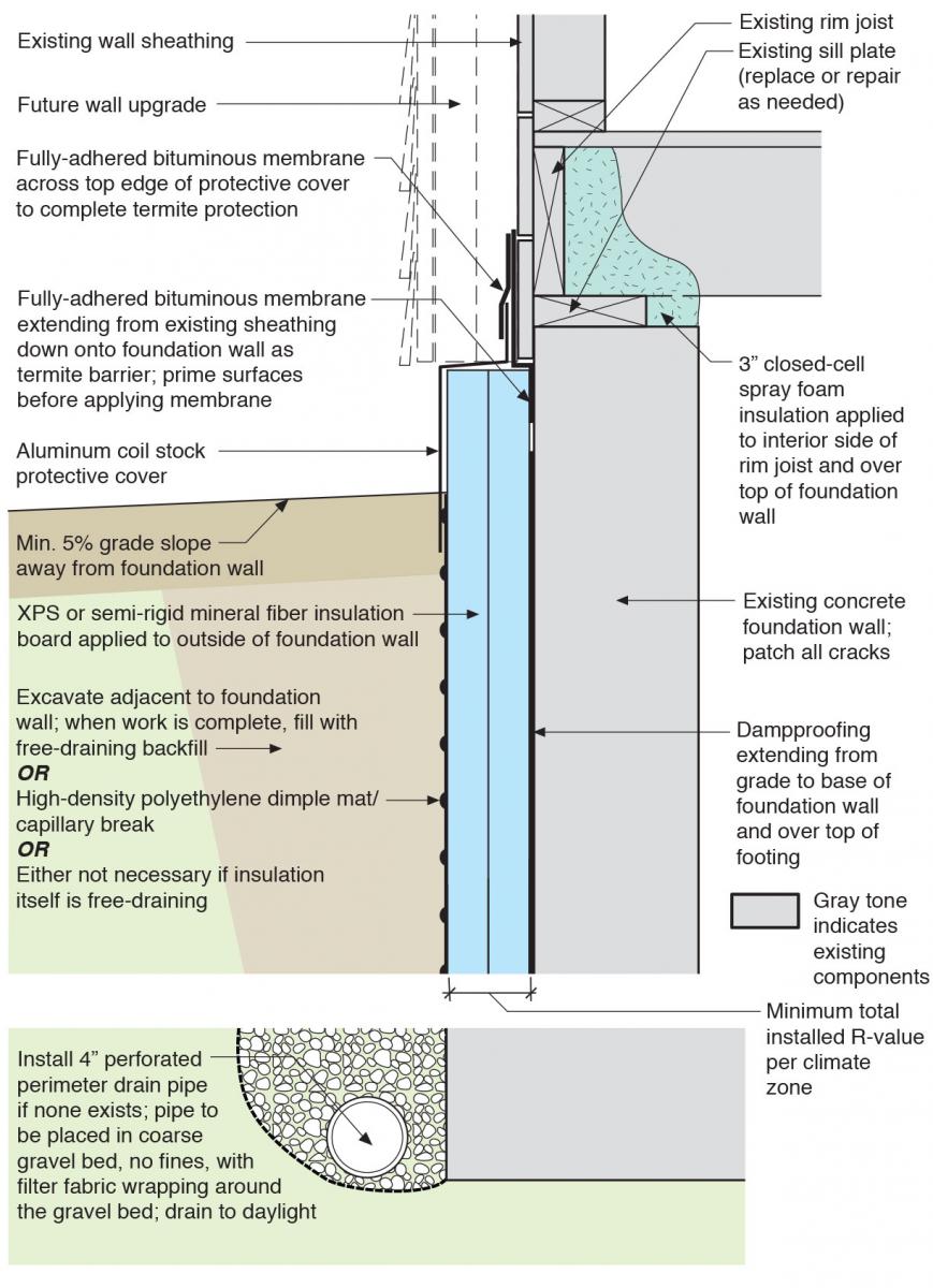
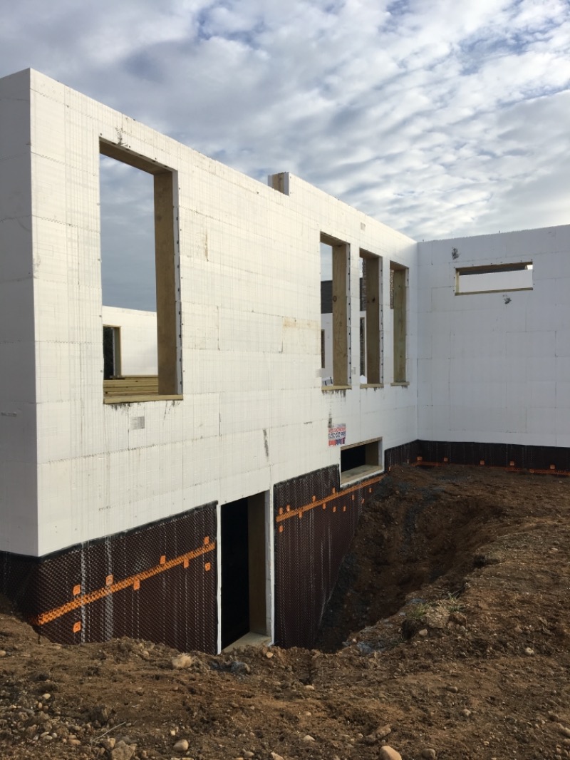
Even though foundation wall materials are water tolerant, measures should be taken to protect the walls from bulk water and a number of strategies can be implemented to this end (see Figure 1). If the grade around the perimeter does not slope away from the house, for example, grading adjustments should be made so that it slopes away at 5% grade for at least the first 3 feet and if possible, 10 feet. If gutters are installed, the downspouts should direct water away from the perimeter of the house and the gutter system must be regularly maintained to prevent overflowing, leaks, or breaks in the system as these can concentrate water at the building’s foundation. A trench of gravel around the perimeter that extends out at least as far as the roof drip edge may also be provided to further mitigate bulk water problems. The gravel trench helps disperse bulk water that comes from the roof so that the top of the foundation wall is not continually splashed. These ground water control strategies should be implemented at the discretion of the practitioner based on project goals and site conditions.
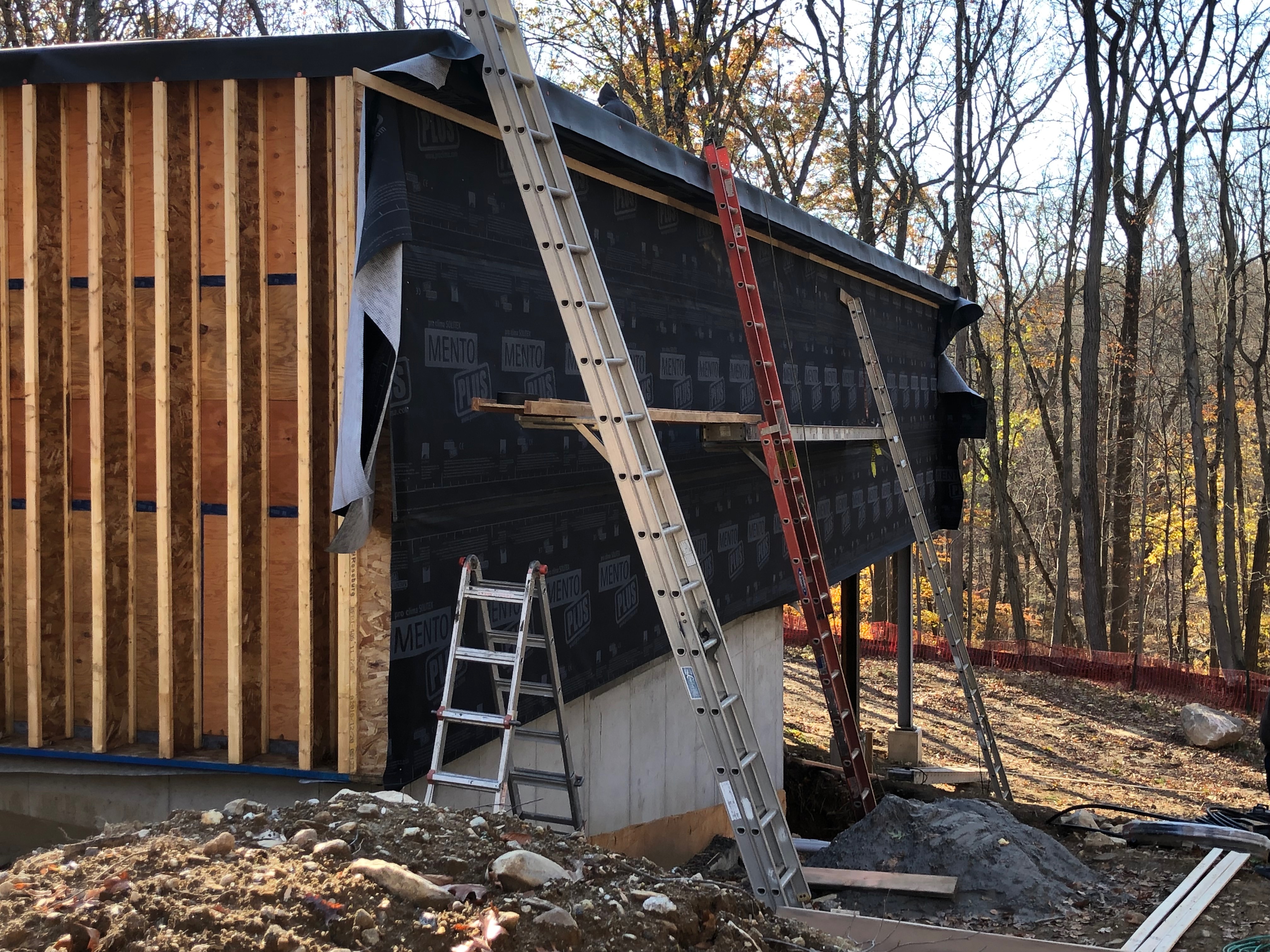
The foundation walls themselves should also be protected from water with damp-proofing or a waterproofing membrane (at the discretion of the practitioner) applied directly to the concrete before installing the rigid foam. A drainage mat of high-density polyethylene dimple mat should be installed over the rigid foam, unless the insulation itself is free draining. The damp-proofing or the waterproofing membrane should be integrated to the water control layer of the sheathing above with a transition strip of self-adhered membrane. This membrane also provides termite protection.
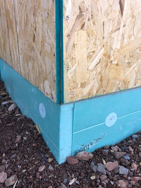
A protective cover of aluminum coil stock or sheet metal should be installed over the top portion of the rigid insulation to provide damage protection and serve as a closure piece. The top edge of this flashing should extend up under the rigid foam sheathing or house wrap and under the cladding. A strip of self-adhered membrane should cover the top edge of this flashing.
How to Install Rigid Board Insulation at Exterior of the Foundation Wall
- Evaluate the existing foundation wall’s structural integrity and ability to tolerate excavation from grade to footing.
NOTE: Rubble wall foundations typically are relatively flush and planar to the interior but highly variable and non-planar on the exterior. For rubble wall foundations, proceed with great care when excavating and/or conduct a small-scale excavation test to assess the rubble wall’s exterior. - Locate underground utilities serving the building or passing near the foundation. Implement measures to ensure the protection of these throughout the project. STOP! Do not proceed if underground utilities are not located.
- Excavate the foundation perimeter down to the footing and 4 feet out from the foundation wall to provide room to work and to accommodate free-draining back-fill material.
- Install a perforated perimeter drain pipe at the footing if none exists. Place the pipe in coarse gravel bed with no fines with filter fabric wrapping around the gravel bed. Slope the drain pipe to a storm water collection system or to a daylight outlet.
- Install damp-proofing or a waterproofing membrane per manufacturer’s recommendations (refer to ENERGY STAR Water Management System Builder Checklist Section 1.5 cited above) extending from grade to the base of the foundation wall and over the top of the footing. Note that primer may be required.
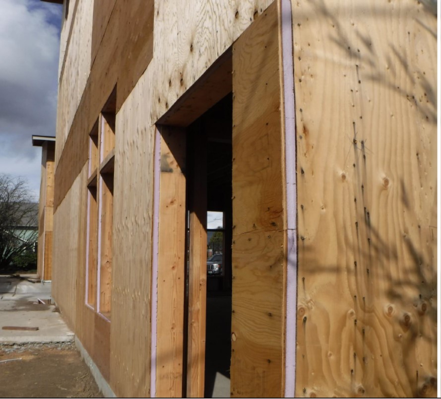
- Provide a transition strip of fully adhered membrane between the wall sheathing and the foundation wall damp-proofing or a waterproofing membrane as a termite protection and to provide continuity of the water control layers above and below grade.
- Install rigid insulation such as XPS, foil-faced polyisocyanurate, or semi-rigid mineral fiber insulation board applied to the outside of the foundation wall. Typically the boards are sufficiently rigid and the spans are small enough to permit the insulation to be loose laid at installation and then held in place by the backfill. The use of adhesives, tape, or temporary supports may be required to hold the insulation in place prior to backfill.
- Install an aluminum coil stock or sheet metal protective cover over the top of the rigid foam; extend it up the wall approximately 4 inches with the top edge extending behind the house wrap or rigid foam drainage plane of the above grade wall. The flashing should extend down over the front face of the rigid foam to approximately 6 inches below grade.
- Install a fully adhered bituminous membrane across the top edge of the metal flashing protective cover to complete the termite protection.
- When work is complete, back-fill the excavation to within no more than 8 inches of the finished grade with free-draining material. Separate the free-draining material from the top soil with filter fabric. Provide a minimum 5% grade slope away from the foundation wall.
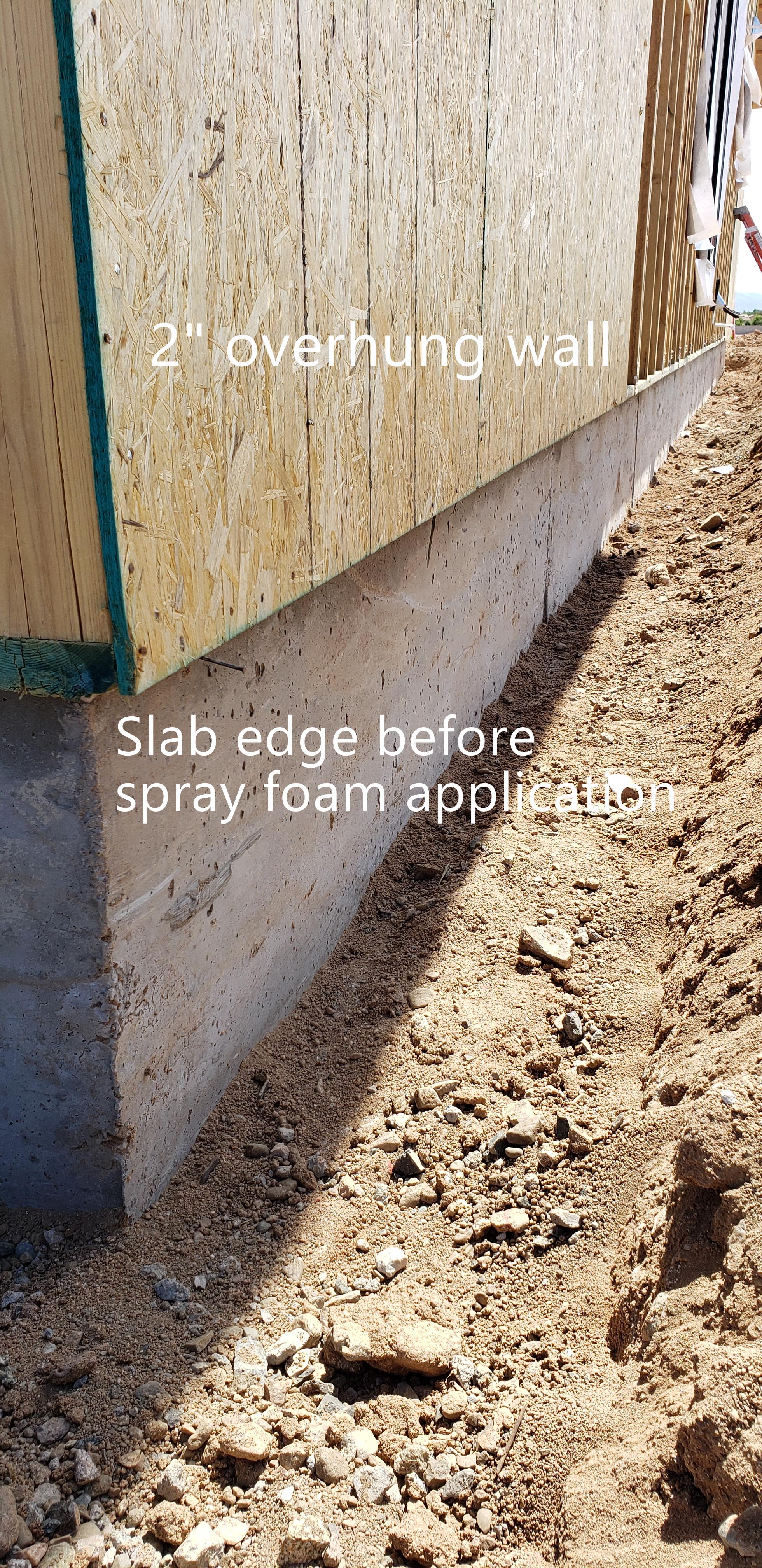
- From the interior, apply 3 inches of closed-cell spray foam insulation to the interior side of the rim joist extending from the top of the foundation wall to the underside of the subfloor. Concrete block or brick foundation walls will require an interior air control layer such as a parge coat applied over the interior face of the wall with a continuous transition to the spray foam at the top of the wall.
Ensuring Success
Locate the underground gas and electric utilities in the vicinity of the excavation.
Provide a fully adhered membrane extending from the existing sheathing down onto the foundation wall to protect the wood framing from termites.
Provide flashing across the top of the exterior insulation and seal it at the top with the membrane to protect the insulation from UV rays and physical damage.
Install a 4-inch perforated perimeter drain pipe in a gravel bed wrapped in filter fabric to allow for proper drainage.
Region
The basement wall assembly should be designed for the specific hygrothermal region, rain exposure zone, and interior climate. The climate zones are shown on the map below, which is taken from Figure C301.1 of the 2012 IECC.
The map in Figure 1 shows the climate zones for states that have adopted energy codes equivalent to the International Energy Conservation Code (IECC) 2009, 12, 15, and 18. The map in Figure 2 shows the climate zones for states that have adopted energy codes equivalent to the IECC 2021. Climate zone-specific requirements specified in the IECC are shown in the Compliance Tab of this guide.
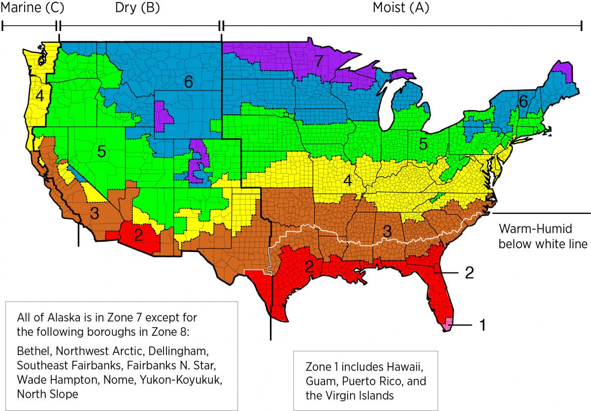
Figure 1. Climate Zone Map from IECC 2009, 12, 15, and 18. (Source: 2012 IECC)

Figure 2. Climate Zone Map from IECC 2021. (Source: 2021 IECC)
The insulation levels should be based on the minimum requirements for vapor control in the current adopted building code and the minimum requirements for thermal control in the current energy code. The minimum insulation requirements for ceilings, walls, floors, and foundations in new homes, as listed in the 2009, 2012, 2015, 2018, and 2021 IECC and IRC, can be found in this table.
Termites
Consult local building code for practices related to termite resistance.
Training
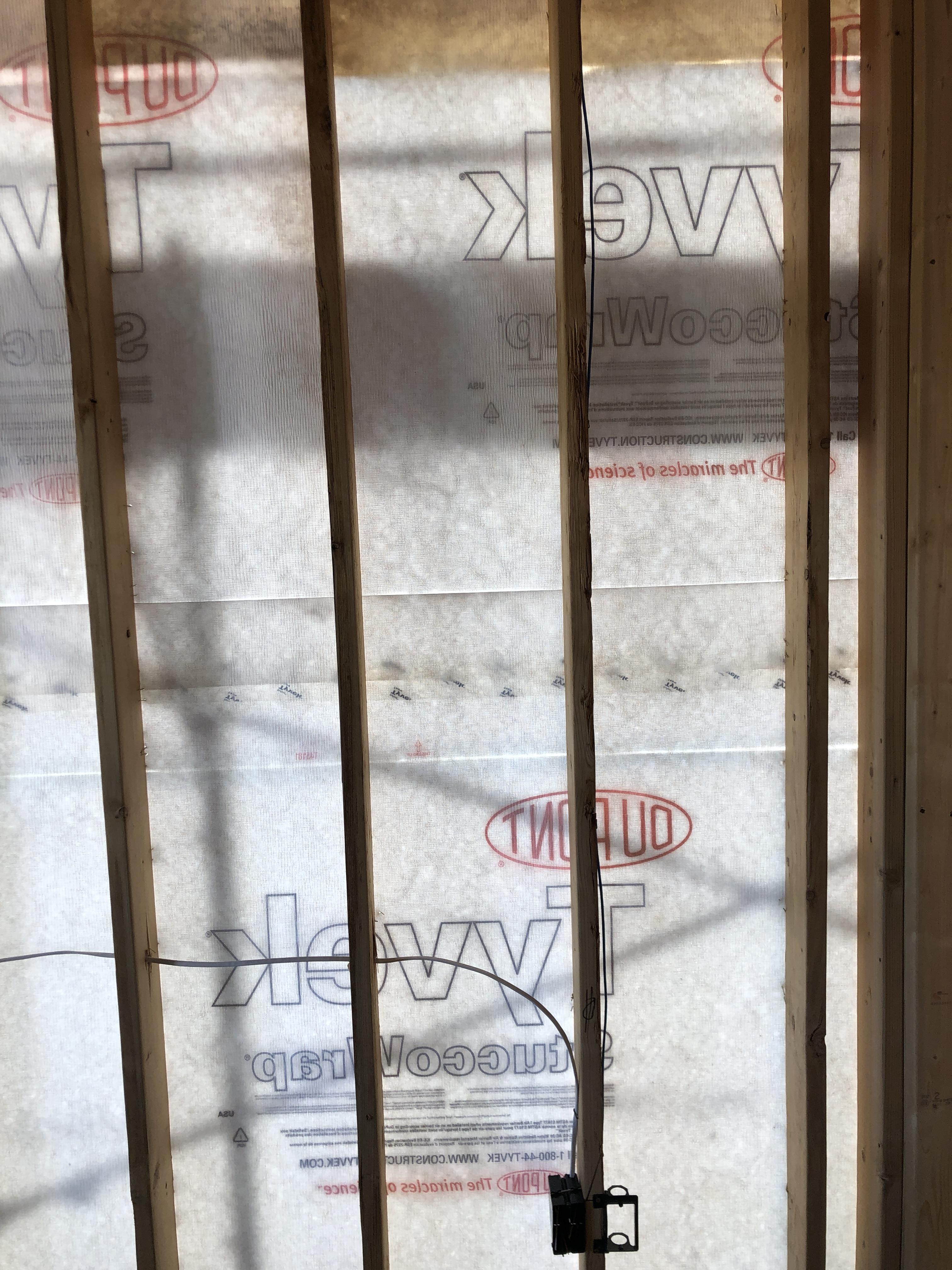
Right and Wrong Images
Source
Source
Source
Source
Source
Source
Source
Source
Source
Source
Source
Source
Presentations
Videos

Compliance
More Info
References and Resources
*For non-dated media, such as websites, the date listed is the date accessed.
Contributors to this Guide
The following authors and organizations contributed to the content in this Guide.
Building Science Corporation, lead for the Building Science Consortium (BSC), a DOE Building America Research Team
Sales
High-R Foundation Insulation = High-Efficiency or Ultra-Efficient Foundation Insulation
Technical Description
There are two levels of foundation insulation: high-efficiency insulation, which meets the 2015 International Energy Conservation Code, and ultra-efficient insulation, which is 25% more efficient than this national code. Using high-efficiency and ultra-efficient insulation, along with professional installation (e.g., no gaps, voids, compression, or misalignment with air barriers; complete air barriers; and minimal thermal bridging) creates conditioned spaces that require very little heating and cooling, along with, even comfort and quiet throughout the house.
Questions? Comments? Contact our webmaster.