

Scope
Retrofit an existing skylight to improve water resistance and improve performance.
- Remove the existing skylight to inspect underlying conditions.
- Repair any damaged framing or sheathing.
- Determine whether to re-install the existing skylight or replace with a new one.
- If the existing skylight is in good shape, relatively new, and meets performance goals of the project (such as reducing heat loss, air loss, and unwanted solar gain), consider keeping it.
- If the existing skylight is damaged, relatively old, or does not meet the project performance goals for insulation value, solar heat gain, and air sealing, consider replacing the unit.
- Install a new skylight unit or re-install the existing unit along with new flashing layers that are properly integrated with new or existing layers of roof sheathing membrane, underlayment, rigid foam, and roof cladding.
For more information on conditions that may be encountered when working in attics, ceilings, and roofs in existing homes, see the assessment guide on attics.
See the U.S. Department of Energy’s Standard Work Specifications for more on skylights. Follow safe work practices as described in the Standard Work Specifications.
See the Compliance Tab for links to related codes and standards and voluntary federal energy-efficiency program requirements.
Description
This guide describes ways to properly retrofit or replace an existing skylight in a sloped roof to ensure that the skylight unit is effectively integrated into the roof’s water control strategy.
Skylights are penetrations through a roof’s water control layer. Weathering of components and improper installation can lessen the effectiveness of the water control layers around the skylight, allowing leaks to occur. They represent a weak spot in the roof’s water management protection system where water could leak into the attic, with the potential to cause significant damage over time. Skylights can also be a significant source of heat loss and unwelcome heat gain, especially with older models that have single-, rather than double- or triple-pane glazing; that lack insulated frames or heat-blocking low-emissivity coatings; or that have developed air leaks.
Any time renovations are conducted that involve the roof, such as reroofing, installers should take the opportunity to inspect the skylights to identify the current equipment, to look for signs of leakage, and to determine if proper flashing and other water management details are in place to prevent future water leaks.
Based on the current conditions and goals of the project, the homeowner and contractor can determine whether to re-install the existing skylight or replace it with a new one. If the existing skylight is in good shape, relatively new, and meets the performance goals of the project (for example reducing heat loss, air loss, and unwanted solar gain), it may be possible to keep it. If the existing skylight is damaged, leaking, or allows too much heat loss, air leakage, or unwanted solar heat gain, consider replacing the unit.
Benefits of Replacing the Skylight
New skylights can provide improved air tightness, energy efficiency, and condensation resistance, compared to older skylights. High-performance skylights have double- or triple-paned insulating glass units (IGUs) with special low-emissivity coatings to help filter UV rays and limit heat transfer, reducing solar heat gain in the summer and heat loss in the winter.
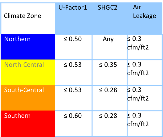
New windows carry a label from the National Fenestration Rating Council showing the window’s U-factor, solar heat gain coefficient (SHGC), visible transmittance, and air leakage ratings:
- U-factor is a measure of heat transfer, the lower the U-factor, the better the window is at stopping heat flow.
- SHGC measures how well the window blocks heat caused by sunlight; the lower the SHGC rating, the less solar heat the window transmits, so a skylight with a higher SHGC might be beneficial in northern climates, while a lower SHGC might be desirable in southern climates and in a skylight located on a south-facing roof.
- Visible transmittance measure how much light comes through a window; the bigger the number, the more clear the glass.
- AL is the air leakage rating and shows air passage through the window assembly measured as cubic feet of air passing through a square foot of window area (cfm/ft2); the lower the AL, the less the window leaks.
ENERGY STAR has climate-specific specifications for doors, windows, and skylights; see Table 1.
A complete replacement also allows for control over the skylight unit’s size, location, placement, and integration with other enclosure retrofit measures. The cost of skylight replacement is high compared to other retrofit measures and is typically a significant disruption to the building occupant. Also, if the replacement skylight unit is not the same size as the original one, extra framing and/or plaster patching on the interior will be required.
Whether installing a new skylight unit or re-installing the existing unit, the skylight should be correctly installed with new flashing layers that are properly integrated with the new or existing layers of roof sheathing membrane, underlayment, rigid foam, and roof cladding, as described in this guide.
Skylight Types
There are two types of skylights commonly available on the market: curb-mounted units and deck-mounted units (Figure 1). The primary difference between the two is that a curb-mounted unit requires additional framing to be installed and waterproofed prior to setting the skylight unit, whereas a deck-mounted unit has an integral curb and attachment flange that allows for the unit to be set and waterproofed directly to the roof deck. Deck-mounted skylights typically have a lower profile and, therefore, are more often used in new construction.
Curb-mounted units have better potential for bulk moisture control and are particularly recommended in skylight replacements where the roof covering is not replaced in conjunction with the skylight or where additional insulation is being added to the top of the roof deck as part of a larger energy efficiency retrofit.
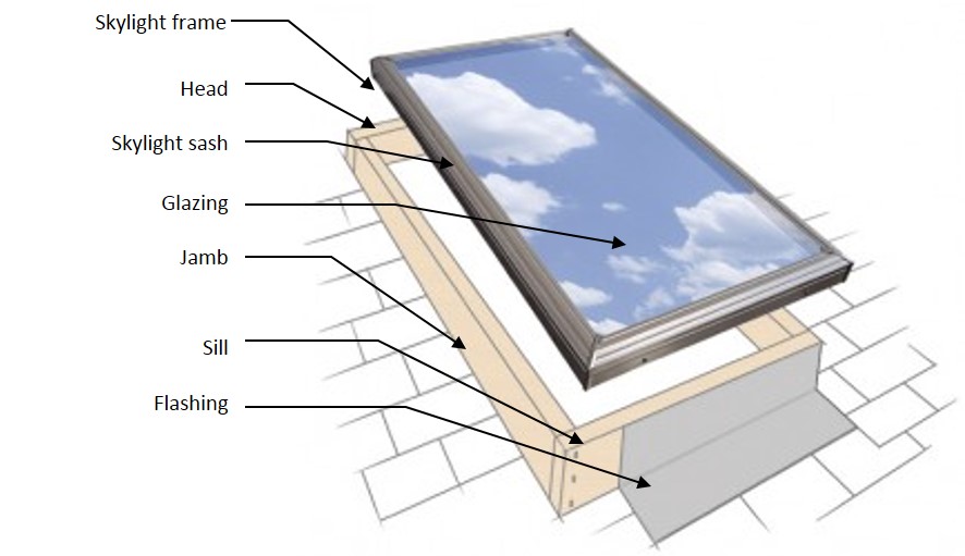
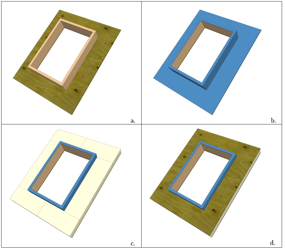
Skylight Unit Components
The parts of a skylight unit are similar to those of a traditional window, with a few added features to keep out the weather (Figure 2).
- Frame: The frame gives the skylight unit its basic shape. Frames can be constructed from wood, metal, or synthetic materials. Framing materials contribute to a skylight’s overall performance values.
- Sash: Operable skylights have a sash. The sash is the framing around the moveable pane. It rests on the fixed frame and holds the moveable glazing in place. In fixed skylights, there is no sash and the frame holds the glazing directly. The sash is typically made of either wood or metal because these materials are resistant to the intense environmental exposure (rain, snow, wind, temperature, and UV) common on roofs.
- Glazing: The glazing is the part of a skylight that lets in light. Traditionally, the glazing is made from glass, acrylic, or polycarbonate. Higher performance products that are double- or triple-paned, with special coatings (to help filter UV rays and reduce heat gain) are becoming more readily available. Insulating Glass Units (IGUs) consist of two or more layers of glass separated by insulated spacers to form a sealed unit that is filled with air or an inert gas like argon; the trapped air or gas provides an insulating layer.
- Weather Stripping: Operable skylights have weather stripping which provides a seal between the sash and the frame to limit water and air infiltration.
- Flashing: Flashing can include strips of metal or self-adhered flexible membrane that provides a weatherproofing layer between the shingles and the skylight and helps to direct rainwater to flow away from the skylight, over the shingles and down the roof toward the gutters.
- Sill: The sill is the bottom of the skylight roof opening in sloped roofs and sloped curbs.
- Head: The head is the top of the skylight roof opening in sloped roofs and sloped curbs.
- Jamb: Jambs are the sides, connecting the sill and the head of the skylight roof opening.

Inspecting for Water Infiltration and Damage
Skylights are among the most common sources of water infiltration issues in a home. Controlling rainwater is the single most important factor in the design and construction of durable roof assemblies. The fundamental principle of water management is to shed water by layering materials in such a way that water is directed downwards and outwards out and away from the building. Roofs are sloped to drain water away from the top of buildings - the steeper the slope, the better. It is vital that any skylights are properly flashed to prevent water entry. The materials that form the water control layer should overlap each other in shingle fashion or be sealed so that water drains down and does not collect on the roof. Membranes or formable flashings around skylights should be integrated into the roof’s drainage plane.
Inspect the interior and exterior of the home before reroofing and/or skylight replacement work begins to determine the current conditions of the roof and skylight and to see if these water management techniques are in place and functioning. Damaged materials should be removed and replaced as part of the retrofit.
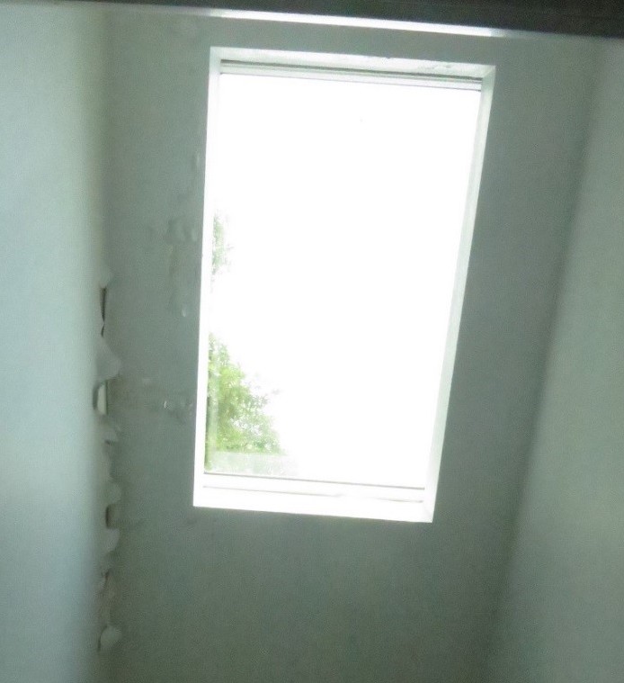
- Inspect from the interior of the home for signs of water infiltration around a skylight including peeling interior paint and water stains on framing (see Figures 3 and 4). It is important to understand the various potential pathways for water infiltration so that any existing water leakage problems can be properly identified and corrected as part of the skylight retrofit work.
Inspect the integrity of the roof covering (roof shingles and underlayment). Check for any deficiencies, water damage, active leaks, etc. Proceed with the skylight retrofit if and only if required repairs have been performed or if the skylight retrofit will address the issues identified.

Figure 4. Water stains on the framing indicate water infiltration at the skylight. - Inspect the structural integrity of the roof sheathing and framing. Check the structure for any deficiencies, rot, insect damage, etc. Proceed with skylight replacement if and only if required repairs have been performed.
- Inspect the skylight for signs of water leakage through the unit itself or between the frame and sash. Common locations of leaks in skylights include through the joints in the skylight frame, between the skylight frame and the sashes (operable units), and through the joint between the skylight and the roof system.
- Test for water leakage by spraying the skylight unit and surrounding roof covering with a garden hose and looking for active water leaks. This must be done with care to not overwhelm the system beyond normal exposure loads. Spraying with too much volume or velocity, or upwards at seals and joints that are normally protected from exposure may lead to leakage that does not occur during normal weather events. Water testing can also lead to damage of interior finishes so care must be taken. If any leaks are discovered, compare to see if they correlate with signs of previous leakage. This type of work is best completed by someone with experience in enclosure forensics and would not be recommended for most home owners.
When to Replace a Skylight
The following types of problems with the unit itself may warrant replacement.
- Failure of the insulated glass unit (IGU) – identified by condensation between the inner and outer panes of glass. Condensation between the panes indicates that the seals of the IGU have failed. The most common cause of IGU seal failure is long-term exposure to water.
- Leaks through joints in the frame – inspect the frame and sash and look for signs of water leakage at the interface of the framing members.
- Leaks through the gaskets or weather stripping (operable units) – Inspect the gaskets or weather stripping between the sash and the frame. Check to ensure that the gasket or weather stripping is not missing, damaged, or worn out. Replacement gaskets and weather stripping may be available. If not, the entire unit man need to be replaced.
Based on the findings, review specific detailing and revise the roof assembly plans as needed to incorporate a new skylight. Follow the minimum requirements of the current adopted building code regarding wood roof framing construction.
How to Repair or Replace a Skylight and Properly Install Flashing around the Skylight
This guide provides steps for the following retrofit situations:
- How to install water management protection around a new or existing skylight unit when tearing off the old roofing and replacing with new roofing.
- Steps for Flashing around a Curb-Mounted Skylight in Conjunction with a Roof Covering Replacement.
- Steps for Flashing around a Deck-Mounted Skylight in Conjunction with a Roof Covering Replacement.
- How to Install Water Management Protection around a New or Existing Skylight Unit as the Sole Scope of Work (no shingle removal) for Curb-Mounted Skylights.
- Steps for Flashing around a Curb-Mounted Skylight as the Sole Scope of Work (no shingle replacement).
- Steps for Flashing around a Deck-Mounted Skylight as the Sole Scope of Work (no shingle replacement).
- How to Install Water Management Protection around a New or Existing Skylight Unit in Conjunction with an Exterior Roof Deck Insulation Retrofit.
How to Install Water Management Protection around a New or Existing Skylight Unit when Tearing Off the Old Roofing and Replacing with New Roofing
If the roof covering is replaced and a new roof water resistive barrier (WRB) is installed, follow the steps below, which are the water management details recommended for new construction. The details would differ slightly depending on whether the skylight is a curb-mounted installation or a deck-mounted installation.
Steps for Flashing around a Curb-Mounted Skylight in Conjunction with a Roof Covering Replacement
Remove the roof covering and underlayment. Remove the metal flashing from around the skylight. Take care not to damage any metal flashing materials that are intended to be reused. Remove the existing skylight unit from the curb (Figure 5a). Inspect the underlying structure for moisture damage, mold, rot, or bugs. If damaged, replace wood curb if needed with dimensional lumber. Determine whether to keep or replace the existing skylight.
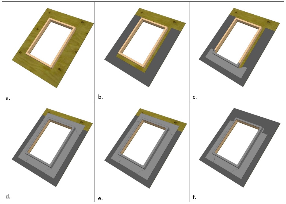
Figure 5. Install roof underlayment and self-adhered flashing around a curb-mounted skylight working from bottom up so upper layers overlap lower layers to shed water away from roof. (Source: Building Science Corporation.) - Working from the bottom up, install roof underlayment around the bottom and sides of the curb (Figure 5b). Install self-adhered membrane flashing over the underlayment at the bottom, then sides of the curb (Figure 5 c and d.). At the top of the unit, install membrane flashing directly to the wood deck (Figure 5e). Then install the roofing underlayment over the top of the flashing (Figure 5f).
Install shingles over the roof underlayment up to the sill (Figure 6a).
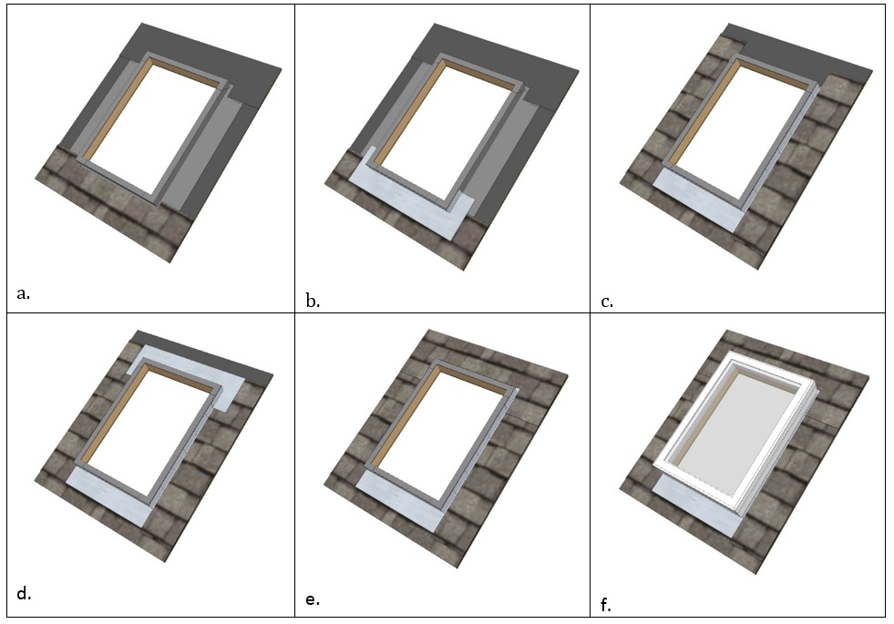
Figure 6. Install roofing and metal flashing around a curb-mounted skylight, integrating flashing with roofing shingles to direct water out and away from roof. (Source: Building Science Corporation.) - Install sill flashing over the shingles (Figure 6b).
- Weave in the step flashing with each course of shingles on the way up the sides of the skylight (Figure 6c). Seal the tops of the screws used to attach the flashing with roof cement to prevent leaks and corrosion.
- Finish off with head flashing across the top of the skylight (Figure 6d).
- Install shingles to cover the head flashing (Figure 6e).
- Set the new or existing skylight in position and fasten to the curb per the manufacturer’s instructions for curb-mounted installation (Figure 6f).
Steps for Flashing around a Deck-Mounted Skylight in Conjunction with a Roof Covering Replacement
Remove the roof covering and underlayment (Figure 7a). Remove the metal flashing from around the skylight. Take care not to damage any metal flashing materials that are intended to be reused. Inspect the underlying structure for moisture damage, mold, rot, or bugs. Replace any damaged wood. (This will likely require removing the existing skylight.) Determine whether to keep or replace the existing skylight. If keeping the existing deck-mounted skylight, it can remain in place provided the skylight is in good condition. If replacing the skylight, remove the old skylight and install the new deck-mounted skylight.
Figure 7. Install roof underlayment and self-adhered flashing around a deck-mounted skylight working from the bottom up so upper layers overlap lower layers to shed water away from the roof. (Source: Building Science Corporation.) - Working from the bottom up, install roof underlayment around the bottom and sides of the curb (Figure 7b). Install self-adhered membrane flashing over underlayment at the bottom, then sides of the curb (Figure 17c and d). At the top of the unit, install membrane flashing directly to the wood deck (Figure 7e). Then install the roofing underlayment over the flashing at the head of the skylight (Figure 7f).
Install shingles over the roof underlayment up to the sill (Figure 8a).
Figure 8. Install roofing and metal flashing around a deck-mounted skylight, integrating flashing with roofing shingles to direct water out and away from roof. (Source: Building Science Corporation.) - Install sill flashing over the shingles at the bottom of the skylight (Figure 8b).
- Weave in the step flashing with each course of shingles on the way up the sides of the skylight (Figure 8c). Seal the tops of the screws used to attach flashing with roof cement to prevent leaks and corrosion.
- Finish off with head flashing the top of the skylight (Figure 8d).
- Install shingles to cover the head flashing (Figure 8e).
- Re-install the removable counter flashing (if present) to complete the installation (Figure 8f).
How to Install Water Management Protection around a New or Existing Skylight Unit as the Sole Scope of Work (no shingle removal) for Curb-Mounted Skylights
The water management installation details for the skylight would differ slightly depending on whether it is a curb-mounted installation or a deck-mounted installation. The intent is to cut back the existing shingles as little as needed to perform the work. With a deck-mounted skylight, this requires the shingles to be cut back further to effectively expose the attachment flange. An alternate approach is to remove an area of shingles around the skylight to create a larger working area. The installation would then be completed like a total roof replacement (see steps above). There is an increased risk of shingle damage with this approach, so it is recommended to have replacement shingles available as needed.
Steps for Flashing around a Curb-Mounted Skylight without Replacing the Roof Shingles)
Cut the shingles and underlayment back 2 inches from the edge of the curb on the sides and 3 inches on the top and bottom of the skylight, to expose the roof decking. Remove the metal flashing from around the skylight. Take care not to damage any metal flashing materials that are intended to be reused. Remove the existing skylight unit from the curb and inspect the underlying structure for damage (Figure 9a). Replace any damaged wood. Determine whether to keep or replace the existing skylight.
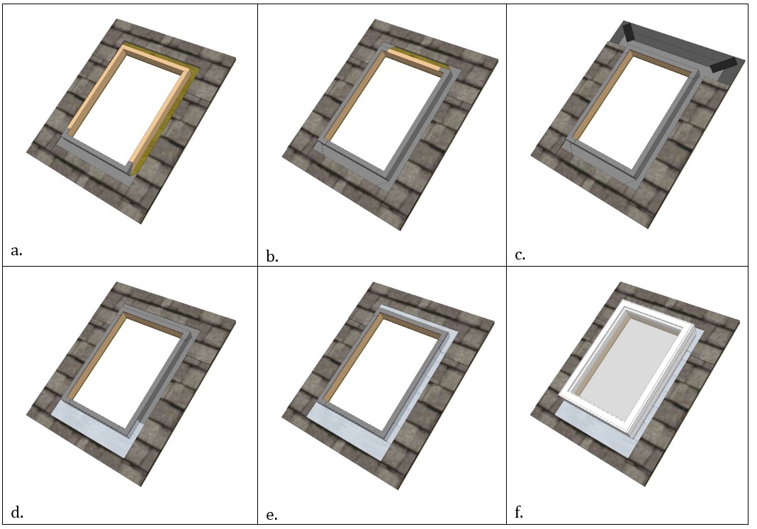
Figure 9. Install self-adhered and metal flashing around a curb-mounted skylight on an existing roof, working from the bottom up so upper layers overlap lower layers to shed water away from the roof. (Source: Building Science Corporation.) - Working from the bottom up, wrap the curb at the sill (Figure 9a) and jamb, or sides (Figure 9b) of the skylight with self-adhered membrane flashing. The membrane flashing should cover and seal the cut edge of the roofing underlayment at the sill and jambs. Carefully lift the cut edge of the shingles to tuck the membrane flashing below the roof shingles, but above the roof underlayment. Above the head of the skylight, cut diagonal slits in the roofing underlayment going up and out from the corners (remove shingles above the head if needed). Then lift the underlayment above the head so that the membrane flashing can be tucked under the roofing underlayment and sealed directly to the wood deck. Tape the cuts in the roofing underlayment after installation of the membrane (Figure 9c). Reposition shingles and replace any that were removed (or wait and replace shingles after installing metal head flashing).
- Install the metal sill flashing over the shingles (Figure 9d).
- Weave in the step flashing with each course of shingles on the way up the sides of the skylight (Figure 9e). Seal the tops of the screws used to attach the flashing with roof cement to prevent leaks and corrosion.
- Finish off with the metal head flashing tucked up under the last course of shingles (Figure 9e).
- Set the new or existing skylight in position and fasten to the curb over the flashing layers per the manufacturer’s instructions (Figure 9f).
Steps for Flashing around a Deck-Mounted Skylight without Replacing the Roof Shingles
Cut the shingles and underlayment back from the edges of the attachment flange of the skylight, cutting back 2 inches on the sides and 3 inches on the top and bottom, to expose the roof decking (Figure 10). If keeping the existing skylight, the deck-mounted skylight can remain in place, provided the skylight is in good condition and no damage to the underlying structure is present. Remove the metal flashing from around the skylight. This may include a removable counter flashing that is attached to the unit itself. Take care not to damage any metal flashing materials that are intended to be reused. If replacing the skylight, remove the old skylight and install the new deck-mounted skylight. Replace any damaged wood. Determine whether to keep or replace the existing skylight.

Figure 10. Install self-adhered and metal flashing around a curb-mounted skylight on an existing roof, working from the bottom up so upper layers overlap lower layers to shed water away from the roof. (Source: Building Science Corporation.) - Working from the bottom up, install self-adhered membrane flashing around the bottom and sides of the skylight, extending from the sides of the curb out over the cut edges of the membrane at the sill (Figure 10b) and jamb (sides) of the skylight (Figure 10c). The membrane flashing should cover and seal the cut edge of the roofing underlayment at the sill and jambs. Carefully lift the cut edge of the shingles to tuck the membrane flashing underneath the roof shingles, but above the roof underlayment. Above the head of the skylight, remove a course of shingles to access the roofing underlayment above the window. Cut diagonal slits in the roofing underlayment so that the membrane flashing can be tucked under the roofing underlayment and sealed directly to the wood deck. Tape the cuts in the roofing underlayment after installation of the membrane (Figure 10d). Replace the shingles over the head of the skylight (Figure 10e) (or wait and replace shingles after installing metal head flashing).
- Install metal sill flashing over the shingles (Figure 10e).
- Weave in the step flashing with each course of shingles on the way up the sides of the skylight (Figure 10f). Seal the tops of the screws used to attach flashing with roof cement to prevent leaks and corrosion.
- Install metal head flashing across the top of the skylight. Tuck it up under the course of the shingles above the skylight (Figure 10f).
- Replace the removable counter flashing (if present) to complete the installation (Figure 10f).
How to Install Water Management Protection around a New or Existing Skylight Unit in Conjunction with Installation of Exterior Roof Deck Rigid Foam Insulation
The following steps describe how to remove and re-install a curb-mounted skylight as part of a reroofing project where rigid foam insulation is going to be installed above the roof deck before installing new roof cladding. These instructions are for curb-mounted, not deck-mounted, skylights.
- Remove the existing skylight unit, as well as all roofing and roof underlayment. Install a curb or replace or extend the existing curb to accommodate the thickness of the rigid foam insulation to be installed above the roof deck, as well as the height of the ventilation space (if there will be one), additional roof sheathing, and the minimum curb height recommended by the roof manufacturer (Figure 11a).
- Apply a strip of air-control membrane around the sides and up over the top of the skylight curb (Figure 11b). If an air control membrane (for example a sprayer-applied or peel-and-stick membrane) is going to be installed over the entire roof deck, this product can be extended around and over the skylight curb.
- Install vertical ventilation battens (furring strips) if used. Then install rigid foam boards to the desired thickness over the roof deck and cut to fit snuggly around the skylight curbs (Figure 11c). If installing more than one layer of foam stagger the seams for additional air and water leakage protection. Note Figure 11c shows a seam in the rigid foam over the window. It is preferable that the top course of foam would be placed so there is no seam over the window.)
- Install a new roof sheathing of plywood or OSB over the rigid foam (Figure 11d) to provide a nailing surface for the roofing material.
- At this point, the installation follows the same steps as a new installation in conjunction with a roof replacement (see Figures 5 and 6 above).
Ensuring Success
Inspect the existing roof framing for any deficiencies and make any repairs necessary.
Ensure that the water control layers of the roof system have no gaps or tears and that all layers overlap each other in shingle fashion to direct water out and away from the room.
Region
ENERGY STAR has climate-specific specifications for doors, windows, and skylights; see Table 1 in the Description tab and see the ENERGY STAR Skylight Specifications (Version 6.0, effective Jan 1, 2016).
Training
Right and Wrong Images
Source
Source
Compliance
More Info
References and Resources
*For non-dated media, such as websites, the date listed is the date accessed.
Contributors to this Guide
The following authors and organizations contributed to the content in this Guide.
Building Science Corporation, lead for the Building Science Consortium (BSC), a DOE Building America Research Team
Sales
Sealed and Flashed Window = Professionally-Installed Window
Technical Description
Windows form a break in a home’s building enclosure that requires special attention to minimize water and air leakage that can compromise the durability and comfort of a home. This protection is provided with flashing that is fully integrated with the home’s weather-resistant barrier. When properly installed, water cannot leak behindthe window assembly. Properly installed windows also include full air sealing around the rough opening. This ensures air gaps are completely draft-free.
Questions? Comments? Contact our webmaster.