



Scope
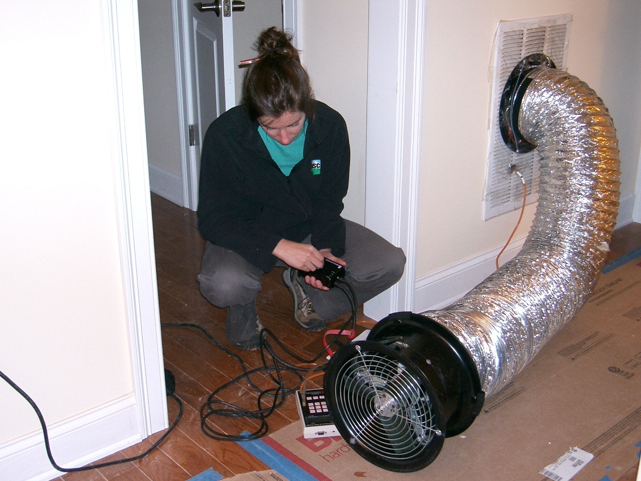
Test heating and cooling duct distribution systems for air leakage using a testing protocol (ANSI/RESNET/ICC 380) approved by Residential Energy Services Network (RESNET). This testing was developed for use in a Home Energy Rating System (HERS) rating and the testing is typically performed by a HERS Rater certified by RESNET.
- Conduct a total duct leakage test at either rough-in (after ducts have been installed and sealed but before drywall or flooring and registers are installed) or at final (after the air handler and ducts, drywall and flooring, and registers have been installed).
- If there is more than one duct system in the home, assess leakage on a per-system, rather than per-home, basis.
- Either visually inspect or perform a total duct leakage test for ventilation ducts.
See the Compliance Tab for links to related codes and standards and voluntary federal energy-efficiency program requirements.
Description
Consequences of Duct Leakage
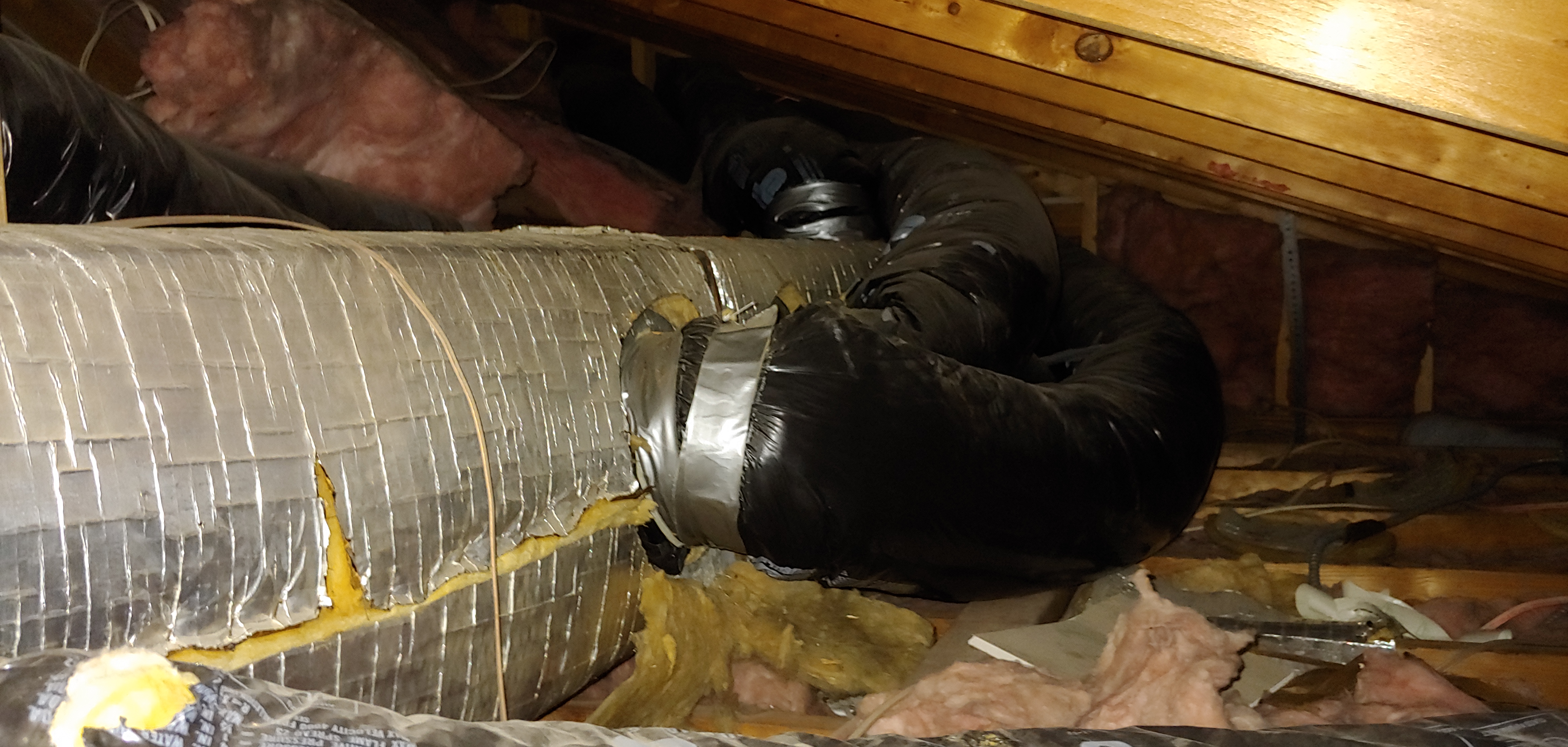
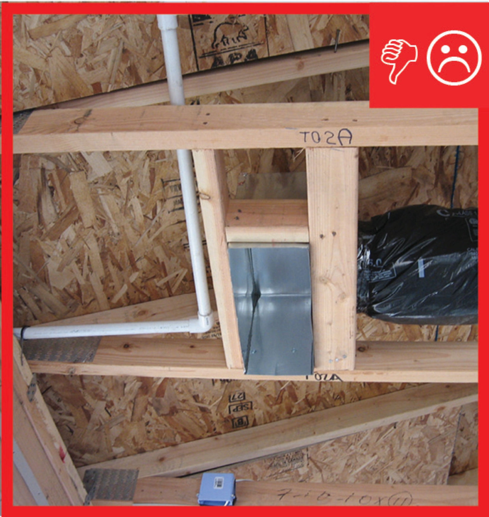
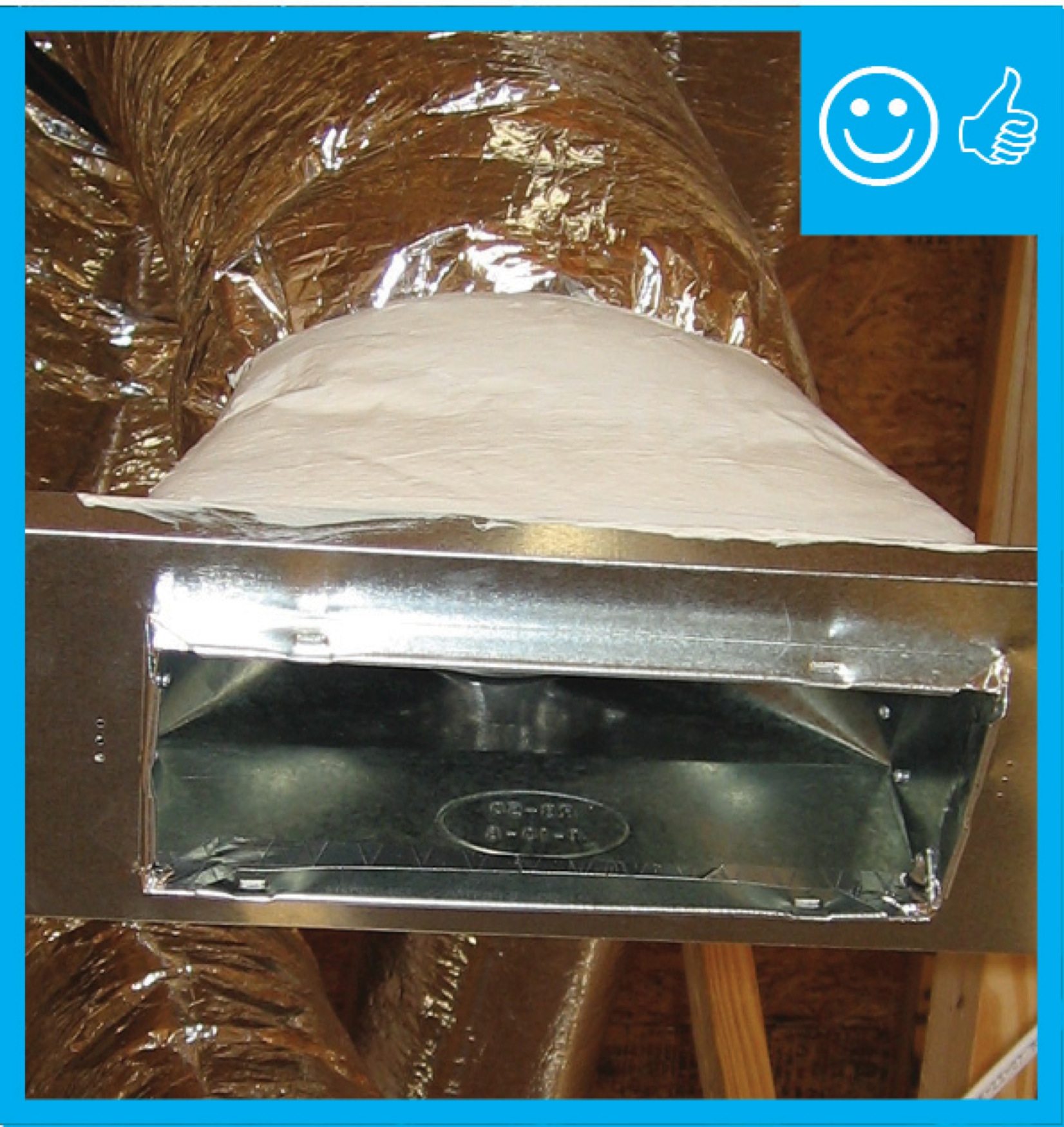
Central forced air heating and cooling systems use ducts to distribute the hot and cold air. If these ducts have loose connections where sections of duct connect to each other or to duct boots or trunk lines or the air handler, air can leak through the cracks (Figure 1). Leaky ducts can be a major source of energy loss and comfort problems and can contribute to moisture and indoor air quality problems, especially when the ducts run through unconditioned space such as a vented attic or crawlspace.
Source
One might question why duct leakage needs to be tested at all if the ducts and air handler are located completely in conditioned space. High-performance homes are built tight using materials that greatly retard heat transfer. As a result, these homes require much smaller heating, ventilation, and air conditioning (HVAC) systems with much less airflow. With less airflow, any amount of duct leakage can starve some areas of the conditioned air they need. Therefore, for balanced distribution of heating and cooling, it becomes even more important that the conditioned air not be lost to duct leakage.
Unintended leaks to the insides of walls and floors can also result in pressurized or depressurized building cavities. These pressures can contribute to moisture transfer inside wall, floor, and ceiling assemblies and in attics and crawl spaces. Unwanted moisture can in turn result in mold growth and rot.
Energy Loss Due to Duct Leakage
Measured duct leakage can be compared to the duct system airflow to get a sense of the energy penalty that duct leaks are contributing. Typical cooling systems move 400 cubic feet of air per minute per ton of cooling. Each cubic foot per minute (CFM) will typically carry with it 30 Btu/h. For example, a 2.5-ton cooling system would be expected to move 1,000 CFM of air and remove 30,000 Btu/h of heat from the home via the air conditioning (AC) system. If that system has a measured duct leakage of 20% (200 CFM25), it is losing - or misplacing - 6,000 Btu/h (1/2 ton) of cooling.
Codes and Standards
Building codes such as the International Residential Code (IRC) and the International Energy Conservation Code (IECC), and energy-efficiency programs like ENERGY STAR Single-Family New Homes require that if a home’s HVAC system includes a duct distribution system, the ducts must be tested for air leakage. Duct leakage is measured and documented by a certified home energy rater using a testing protocol approved by the Residential Energy Services Network, Inc. (RESNET). The complete accepted protocols are found in ANSI/RESNET/ICC Standard 380.
Equipment
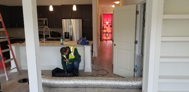
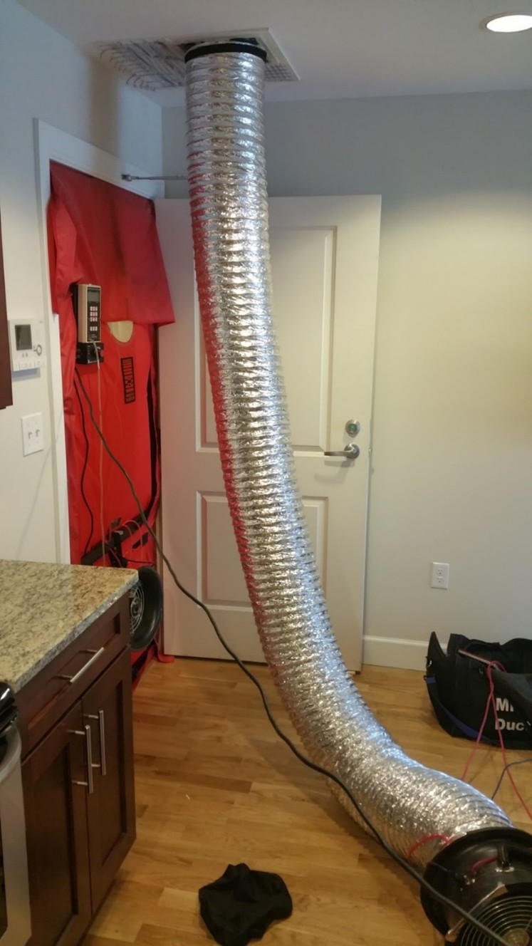
As required by RESNET standards, the test is performed using specific duct testing equipment. The duct testing equipment consists of two main components: a calibrated fan that is used to either pressurize or depressurize the duct, and a device called a manometer that is used to measure fan flow and building pressure. Testing also requires supplies such as cardboard and tape or adhesive plastic sheeting to seal off the supply and return registers during the test, and hoses for measurement of various pressures by the manometer. See Figure 2.
Pressurization and Leakage Measurement
The fan is used to pressurize or depressurize the duct system to 25 pascals (Pa) or 0.10 inch water column (in. WC). Once at 25 Pa pressure, the airflow through the duct tester is read in cubic feet of airflow per minute at 25 Pa; this duct leakage measurement is abbreviated as CFM@25Pa or simply CFM25.
Testing for Total Duct Leakage and Duct Leakage to the Outdoors
Two types of tests may be performed: total duct leakage and leakage to the outdoors.
The “total duct leakage” test measures air leakage from all of the ductwork connected to the HVAC system, whether located inside or outside the building’s thermal envelope. This includes both supply and return ducts. Air leakage from the HVAC equipment cabinets is also accounted for in this test.
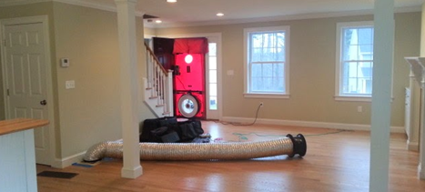
The "duct leakage-to-outside" test measures only air leakage from the ductwork to the outside of the home’s conditioned space. For example, this air leakage could be to an unconditioned attic, crawlspace, basement or garage, or directly to the outdoors. Duct leakage also happens inside wall, floor and ceiling cavities that may indirectly leak to the outside of the conditioned space. The "duct leakage-to-outside" measurement is accomplished by pressurizing the conditioned space with a blower door in the same way as in an enclosure leakage test. The conditioned space is pressurized or depressurized to match to the duct leakage test pressure (Figure 3). In this balanced pressure condition, there is negligible pressure difference between pressurized ductwork and the pressurized conditioned space, and the result is that the duct test measures only the leakage of the ductwork to the outside of the conditioned space.
Source
According to ENERGY STAR for Homes, for ducts in unconditioned spaces such as unconditioned vented attics, crawlspaces or basements, both total duct leakage and leakage to outdoors tests should be conducted. However, when all ducts are located in conditioned spaces, only the total duct leakage test needs to be conducted when certain conditions exist. Testing of duct leakage to outdoors can also be waived in accordance with the 2nd or 3rd alternative of ANSI / RESNET / ICC Std. 301-2022, Table 4.2.2 (1), footnote (w). Alternatively, for the sake of meeting a compliance limit for duct leakage to outdoors, testing of duct leakage to outdoors can be waived in accordance with Section 5.5.2 of ANSI / RESNET / ICC Std. 380-2022, if the total duct leakage measurement is used in place of the duct leakage to outside measurement.
When to Perform the Test
Testing can be performed at either rough-in or final testing.
“Rough-in” testing is when ducts have been installed and sealed but before drywall or flooring and registers are installed. This can be before installation of cabinets (e.g., kitchen, bath, or multimedia) or ductwork that connects duct boots to toe-kick registers. Rough tests may or may not include the air handler depending on whether one is installed at the time of the test.
“Final” testing is after the air handler and ducts, drywall, flooring, and registers have been installed. If testing is conducted at final, registers installed over carpets are permitted to be removed and the face of the duct boot temporarily sealed during testing. The Rater must also visually verify that the duct boots have been durably sealed to the subfloor (using duct mastic or caulk) to prevent leakage during normal operation.
ENERGY STAR for Homes allows total duct leakage to be tested at either rough-in or final. If testing is done during rough-in, the Rater must visually confirm that the duct boot is sealed to the drywall after drywall has been installed. If testing is done at final, this visual check can also be done then. If the total duct leakage testing will be done at final, ducts should be visually inspected at rough-in to look for any obvious gaps or misses in duct sealing so those can be corrected before drywall is installed.
There are pros and cons to either method. Some builders prefer to test for duct leakage at rough-in when the ducts are easier to access in case additional air-sealing needs to be done. Some Raters will perform a diagnostic test at rough-in with a fog machine connected to one of the ducts and the other registers closed off so that the HVAC contractor can visually identify leaks in the ductwork which require additional sealing.
Some builders, especially those who install ducts in the attic, prefer to wait until final to test the ducts because the ducts are likely to get moved about and possibly damaged in the meantime, and ducts in the attic will still be accessible at a final inspection.
Leakage to outside is usually only able to be tested at a final test because this test requires the building envelope to be pressurized to match the pressure of the duct test, however the building’s pressure envelope is typically incomplete at the time of rough testing and not able to be pressurized.
Whenever possible, it is recommended that duct leakage testing should be performed at final, after all components of the system have been installed, including the air handler, the ductwork, and the register boxes also commonly known as duct boots.
ENERGY STAR Single Family Duct Leakage Criteria
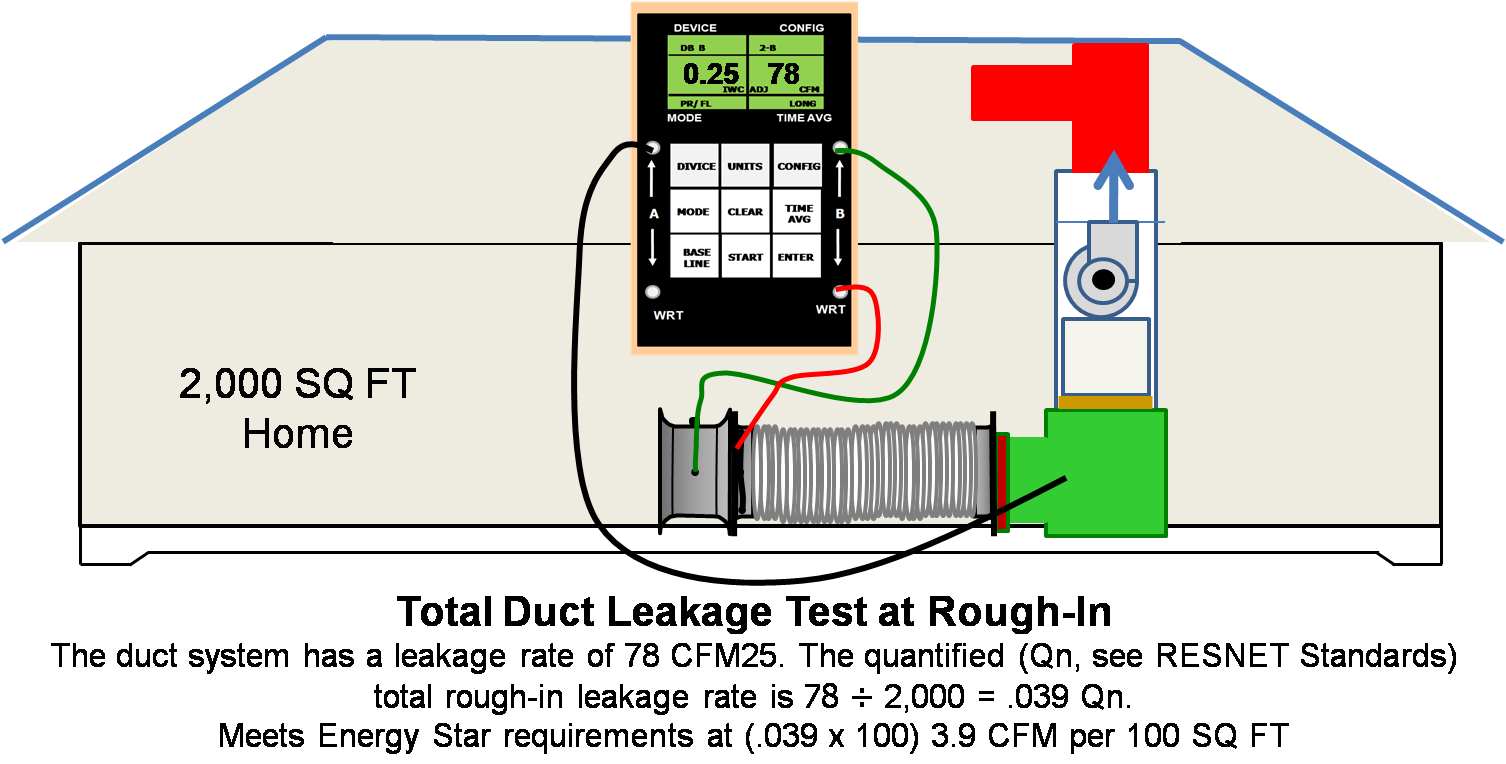
The ENERGY STAR Single-Family New Homes (SFNC) V3 total duct leakage criteria in the National Rater Field Checklist specify that total duct air leakage at rough-in must be ≤ 4 CFM25 per 100 ft2 of conditioned floor area or ≤ 40 CFM25; or total duct air leakage at final must be ≤ 8 CFM25 per 100 ft2 of conditioned floor area or ≤ 80 CFM25. See Figures 4 and 5.
Source
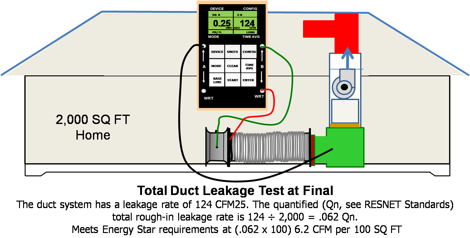
Source
Leakage limits are assessed on a per-system, rather than per-home, basis. So, for example, if a home has two furnaces, duct leakage must be measured in each system and compared to the conditioned floor area that is served by that duct system. Each system must meet the “total” and “outdoors” leakage requirements to qualify for the ENERGY STAR program.
ENERGY STAR Multifamily Duct Leakage Criteria
ENERGY STAR Multifamily New Construction (MFNC) V1 total duct leakage criteria specified in the National Rater Field Checklist varies depending on the number of ducted returns in the duct system.
For rough testing of a duct system with no ducted returns, the total duct air leakage must be ≤ 3 CFM25 per 100 ft2 of conditioned floor area or ≤ 30 CFM25.
- With one or two ducted returns, the total duct air leakage must be ≤ 4 CFM25 per 100 ft2 of conditioned floor area or ≤ 40 CFM25.
- With three or more ducted returns, the total duct air leakage must be ≤ 6 CFM25 per 100 ft2 of conditioned floor area or ≤ 60 CFM25.
For final testing of a duct system with no ducted returns, the total duct air leakage must be ≤ 6 CFM25 per 100 ft2 of conditioned floor area or ≤ 60 CFM25.
- With one or two ducted returns, the total duct air leakage must be ≤ 8 CFM25 per 100 ft2 of conditioned floor area or ≤ 80 CFM25.
- With three or more ducted returns, the total duct air leakage must be ≤ 12 CFM25 per 100 ft2 of conditioned floor area or ≤ 120 CFM25.
Residential IECC Duct Leakage Criteria
IECC residential duct testing requirements were introduced in the 2009 IECC. The limits for these tests have been very consistent requiring total duct leakage ≤ 4 CFM25 per 100 ft2 of conditioned floor area from the 2012 IECC to the 2021 IECC.
These tests were not required for duct systems which were entirely within the building thermal envelope until the 2021 IECC which implemented a new total leakage test at final limit of ≤ 8 CFM25 per 100 ft2 of conditioned floor area required for ducts entirely within the building thermal envelope.
How to Prepare Filters, Dampers and Attached Ventilation Ducts for Duct Leakage Testing
- Remove all filters within the duct system or at the air handler cabinet. Also remove any filter at a return grille when that return grille is used for the attachment of the duct tester.
- Any ventilation ducts that connect to the heating and cooling ductwork should have motorized dampers that should be closed for the heating and cooling duct leakage test. Ventilation ductwork must not be additionally sealed for the test unless the ventilation system runs continuously. If the ventilation system runs continuously (not on-demand and not intermittently on a timer or other control), the ventilation ducts can be temporarily sealed to the outside wherever feasible (Figure 6).
- Zone dampers and fire dampers should be confirmed to be fully open during the test. If these damper positions cannot be visually confirmed to be open, the static pressure in register box ducts on the distribution side of these dampers should be verified during duct testing to check that the dampers are open.
- Volume dampers should be left in their as-found condition if the system has already been balanced, but should be confirmed to be open if the system has not yet been balanced.
It is best practice that static pressure in all parts of the supply and return sides should be within 10% of the duct test pressure to ensure dampers are open and to have an accurate and repeatable duct leakage test.
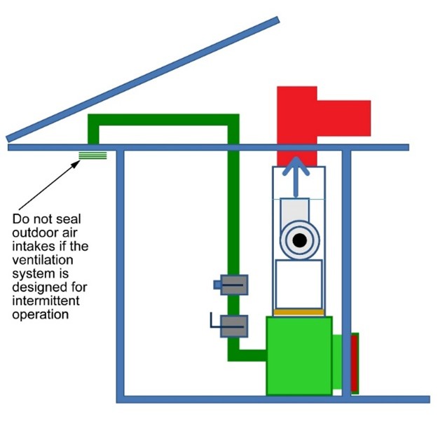
Source
How to Prepare Duct Openings for Duct Leakage Testing at Rough-in
- For duct testing at rough-in, perform the test after ducts and register boxes are installed, and before drywall, finished flooring, and registers are installed. If there are any cabinets that connect register boxes to toe-kick registers, they do not need to be installed.
- Temporarily seal all interior duct terminations at the opening of the supply and return register boxes at the register side of the register box using cardboard and tape, reusable covers, or removable adhesive plastic (Figures 7 and 8).
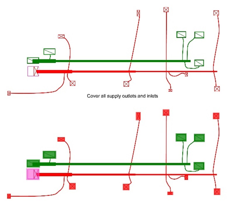
Source
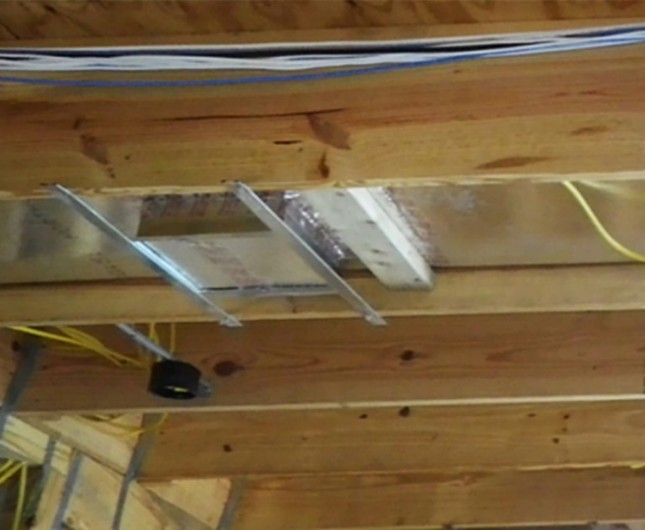
Source
How to Prepare Duct Openings for Duct Leakage Testing at Final
- For duct testing at final, perform the test after the ducts and duct boots (register boxes) are installed, and after drywall, finished flooring, and registers are installed. If there are any cabinets that connect register boxes to toe-kick registers, they should be installed at this time.
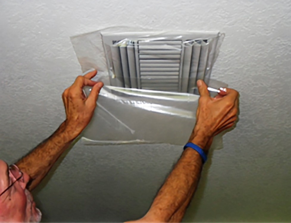
- Temporarily seal all interior duct terminations at the outside face of the supply and return registers using cardboard and tape, reusable covers, or removable adhesive plastic (Figures 7, 8 and 9).
- RESNET and ENERGY STAR both allow an exception for registers atop carpets in which these registers may be removed and the register box sealed at the subfloor, provided that the joint between the register box and subfloor is visually confirmed to be sealed.
Source
How to Connect a Duct Tester at Rough-in Without an Air Handler Installed
- Connect the duct tester by attaching the flex duct and collar that comes with the duct tester to the open supply or return trunk with suitable tape and seal off the rest of the register box openings.
How to Connect a Duct Test Fan at Rough-in or Final with an Air Handler Installed
- Use the flex duct and collar that comes with the duct tester to connect the duct tester to the largest return duct register box or grille, or air hander fan compartment with suitable tape.
- Set up the duct tester to either pressurize or depressurize the duct system following the manufacturer’s instructions.
How to Set Up the Manometer and Pressure Hoses
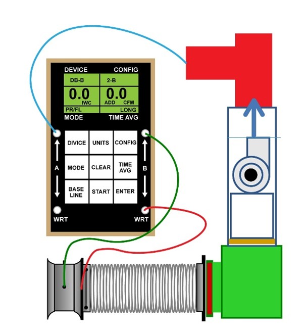
- Set up the manometer with hoses connected to measure fan pressure and reference pressure according to the manufacturer’s instructions for pressurization or depressurization. Be aware that the manometer hose connections may be different for different manufacturers and may be dependent on whether the system is being pressurized or depressurized.
- Connect a hose from the "input" pressure tap of the manometer to the supply register which is closest to the air handler (the blue tube in Figure 10). Alternatively, if performing a duct leakage test of the return side before the air handler is installed, connect the reference pressure hose to the nearest sealed return register opening.
- For a total duct leakage test, a window or door should be open to the outside so that the airflow from duct tester itself doesn’t pressurize or depressurize the building and result in a different duct test pressure for ducts inside the conditioned space versus outside the conditioned envelope.
- For leakage to outside testing, the test pressure reference channel should be connected to the inside of the conditioned space.
Source
How to Run a Total Duct Leakage Test
- Turn on the fan to pressurize (or depressurize) the ductwork to 25 Pa.
- Once a steady 25 Pa is reached in the duct system, note the manometer reading for CFM. This reading of the fan airflow needed to maintain 25 Pa is the amount of air escaping through the leaks in the duct system, indicated in CFM.
How to Run a Leakage to Outside Test
- A leakage to outside test requires the conditioned space of the home to be pressurized or depressurized to the same pressure as the duct test pressure.
- Use the same test set up from the Total Duct Leakage test above.
- Close all doors and windows and hatches between conditioned and unconditioned space.
- Unconditioned basements or attics should be opened to the outside whenever possible.
- A blower door should be set up on an entrance to the home and operated the same way as for a single point enclosure leakage test.
- Using the blower door fan, adjust the building pressure to 25 +/- 0.5 Pa and leave it running while the Leakage to Outside test is performed on the ducts.
- Adjust the duct tester fan until the duct pressure referenced to the interior of the conditioned space is within +/- 0.5 Pa of 0 Pa.
- When this adjustment is complete, return to the envelope test fan and make sure the building pressure is still at the nominal duct test pressure, and adjust it to 25 +/- 0.5Pa again if necessary.
- Then return to the duct test fan and record the duct leakage when the duct pressure is within +/- 0.5 Pa of 0 Pa.
If the leakage is higher than the goal for the project, search for and illustrate areas of duct leakage.
When the duct test is over, unseal all temporary air seals and replace filters and equipment covers and generally return the building and equipment to the as-found condition.
Ensuring Success
After ducts are installed and before drywall is installed, the duct system should be visually inspected by a HERS (home energy rating score) rater to ensure that all duct connections are properly fastened and sealed, preferably with mastic. The rater should also visually inspect at rough-in that ducts are fully insulated to the applicable standards for the project.
If duct leakage is tested at rough-in, the person performing the test should confirm and document that total duct leakage meets the applicable test limits and then they should also verify with a visual inspection that duct boots are sealed to finish surfaces at a follow up inspection.
When duct leakage testing is planned to be conducted at final inspections, a cautious builder may choose to also perform an additional duct test prior to drywall installation and potentially make use of a theatrical smoke machine during pressurization testing to look for air leaks so they can be sealed before drywalling.
On older homes, non-ducted wall cavities and ceiling plenums were often used as part of the return air distribution system. Duct leakage tests can result in extremely high total duct leakage in these cases. However, they may have very low duct leakage-to-outside results. It is a problematic condition that can result in depressurization of interstitial cavities and air quality concerns, and it is no longer allowed in new construction.
A check for this condition can be a simple visual inspection into the ductwork from the return grille. A fiber optic scope can be used to look farther into ductwork.
Another way to check for high duct leakage on the return duct side of the test is to compare the pressure in the return ductwork near the duct tester to the pressure in the supply ductwork. If the pressure in the return is much higher than the pressure in the supply, this can indicate relatively high leakage in the return distribution system. However, one should also be aware that a partial blockage in the ductwork or air handler can also result in this type of pressure condition.
Applying theatrical fog to a duct system during a positive pressure test can also help quickly identify areas of significant duct leakage.
Region
No climate specific information applies.
Training
Right and Wrong Images
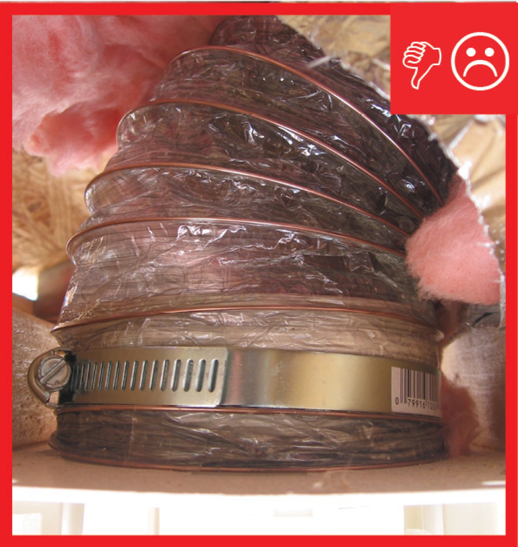
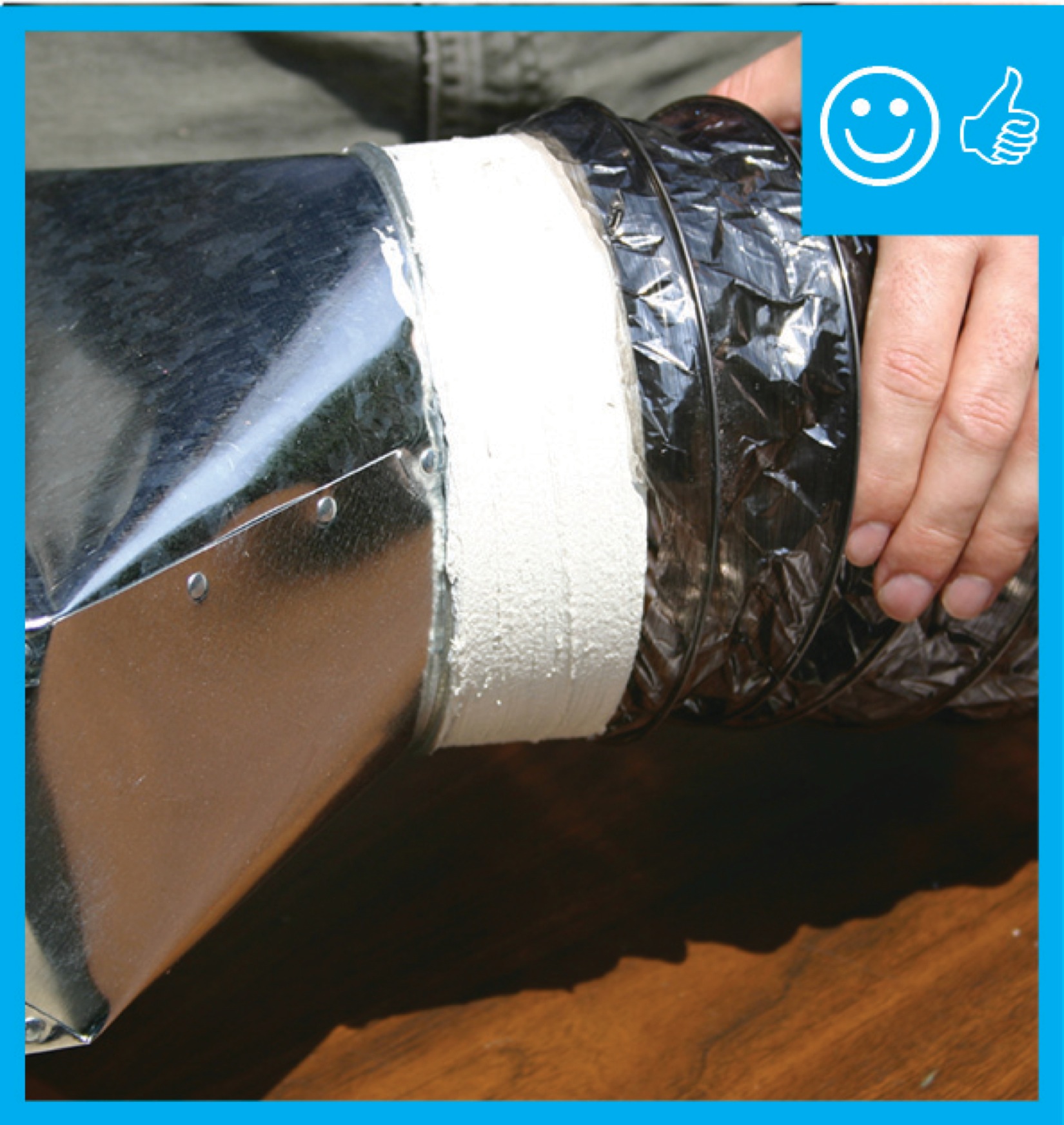

Source
Source
Source
Videos
Compliance
Retrofit
The information provided for testing duct leakage in new homes applies to testing duct leakage in existing homes as well.
For more on duct sealing, see the U.S. Department of Energy's Standard Work Specifications.
More Info
References and Resources
*For non-dated media, such as websites, the date listed is the date accessed.
Contributors to this Guide
The following authors and organizations contributed to the content in this Guide.
The following authors and organizations contributed to the content in this guide.
Advanced Building Analysis, LLC
Calcs-Plus
Pacific Northwest National Laboratory
Questions? Comments? Contact our webmaster.