



Scope

Test central ventilation and exhaust systems for duct leakage to reduce energy waste, improve system performance, and mitigate indoor air quality issues.
- Determine whether to test at rough-in or at final.
- Determine whether to test the entire duct system or just a portion.
- Determine the test pressure to use.
- Calculate the air leakage allowance.
- Prepare and perform the leakage test.
- Investigate and perform necessary diagnostics.
- Record results.
See the Compliance Tab for links to related codes and standards and voluntary federal energy-efficiency program requirements.
Description
Testing the air tightness of central ventilation duct systems for new construction provides quality control which helps buildings to achieve optimal levels of ventilation effectiveness and efficiency. This guide covers duct leakage testing of central ventilation systems with a focus on meeting the particular requirements of the ENERGY STAR Multifamily New Construction (ES MFNC) program (V1.1 and 1.2), but the means and methods used are widely applicable to all buildings with centrally ducted ventilation systems.
This guide covers the following key points of the testing methods themselves:
- Duct air leakage allowance and duct test pressure
- When to test and whether to test portions of a duct system and/or an entire duct system
- Best practices to ensure an accurate test
- Reporting the results of a test.
Background
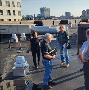
With ever-improving standards of envelope airtightness in construction, it becomes increasingly important to deliver fresh air to all living spaces and to extract humid and stale air from key locations including bathrooms and kitchens. Since the 1960s, the most common type of ventilation in multifamily buildings has been central exhaust ventilation. These systems can be recognized by the mushroom-shaped rooftop fans that are scattered across the roofs of many multifamily rooftops (Figure 1).
Source
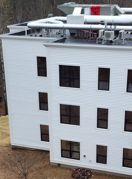
Another common type of central system provides both supply ventilation and exhaust from the same central unit located on the roof (Figure 2). These systems often incorporate energy recovery and are referred to as energy recovery ventilation systems (ERVs).

Source
Air Leakage in Ventilation Systems
Research in the early 2000s found that significant duct leakage existed in the many central exhaust systems found in high-rise multifamily buildings in and around New York City (NYSERDA 2011 ). This research found that leaky ductwork caused over 50% of the total airflow exhausted by the rooftop fans to be drawn from random building cavities rather than from the intended bathrooms and kitchens. This resulted in significant energy waste due to infiltration of unconditioned air, increased exhaust fan power to move the additional air, and increased difficulty in providing proper exhaust to the spaces where it was needed.
Effects of Leaky Ventilation Systems
Leaky ductwork can cause the following issues:
- Fan energy waste due to increased fan power from moving more air
- HVAC energy waste due to increased infiltration of unconditioned air into the building
- Poor system performance - insufficient ventilation in some areas, over-ventilation in other areas
- Moisture issues such as condensation and mold growth
- Comfort issues
- Increased time, hassle, and cost during system balancing
- Increased equipment cost due to larger fans.
To perform as designed, airflows of ventilation systems must be adjusted to deliver and extract the designed airflow for (and from) each living space. Leaky ductwork can make the job of balancing a ventilation system difficult or even impossible. Even today, standard practice is often to install larger fans than necessary to compensate for leaky ductwork.
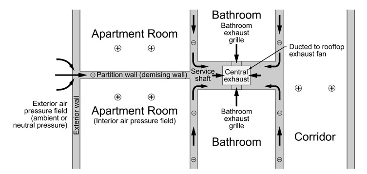
With leaky ductwork, the pressures caused by duct leakage can push or pull air through interstitial cavities and shafts of buildings, causing moisture and air quality issues (Figure 2). This transferred air can be warm and can be humid from either the exterior or interior environment. The can lead to condensation on cooler interstitial surfaces. This condensation in turn can contribute to mold or other biological growth (BSC 2014).
Source
When ventilation air is delivered by an exhaust-only system, interstitial negative pressures are at their worst, since there is no possibility of inducing positive pressures due to leakage from supply ventilation ductwork.
When ventilation air is delivered by a Heat Recovery Ventilator (HRV) or Energy Recovery Ventilator (ERV), it is important that the flow rate of exhaust air is equal to the flow rate of supply air to achieve the nominal recovery efficiency of the system, and in this case airtightness of both exhaust and supply ductwork is important to achieving good performance and minimizing issues associated with induced interstitial pressures.
See the BASC guide Pre-Retrofit Assessment of Ventilation Systems for more detailed discussion of the benefits of tight ductwork for ventilation systems.
Duct Leakage Testing Requirements
To avoid problems caused by leaky ductwork and to reduce energy consumption, the EPA’s ENERGY STAR Multifamily New Construction Program has a requirement for testing the airtightness of central exhaust ventilation duct work. This type of test can help ensure that ventilation air systems can be satisfactorily balanced. The ENERGY STAR Multifamily New Construction Program and its requirements are also incorporated into other programs such as the DOE Zero Energy Ready Home (ZERH) Multifamily Version 2, municipal and state energy codes, and the 45L federal tax credit beginning with the 2023 Tax Year. Other duct leakage test standards that may be applied to central ventilation ductwork include SMACNA’s 2012 HVAC Air Duct Leakage Test Manual, ASTM E1554, and ANSI/RESNET/ICC 380. The benefits of airtight ductwork include reduced energy use, increased longevity of ventilation fans, and better indoor air quality when the design ventilation rates are achieved.
The exhaust portion of the ductwork of an exhaust system or central balanced system (ERV or HRV) requires leakage testing per the current ENERGY STAR Multifamily New Construction Program (V 1.2), but the requirement does not explicitly include testing supply ducts. However, it is important to control and minimize air leakage in both exhaust and supply ductwork. Best practice is to test both aspects of the system (Figure 4).
Source
Duct Leakage Testing
When preparing for a central ventilation duct leakage test, develop a test plan that addresses each of the following.
- scheduling
- test pressure
- air leakage limit
- test equipment
- test procedure
- reporting results.
Scheduling
Testing can be done at the time of rough-in mechanical installations, or at a final phase when the project is near completion. There are pros and cons to testing at either time.
Testing at Rough-In
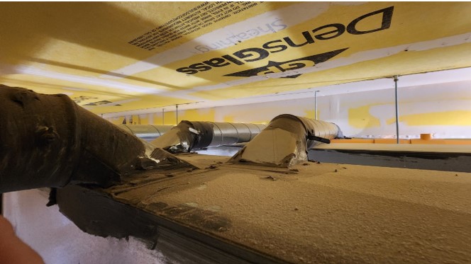
During the rough-in phase of construction, it is common for the duct system to not be entirely installed at the time of testing (Figure 5). The benefit of testing during this phase is that any failures can be addressed early. The leaks in the system are typically more accessible for traditional sealing methods and can be retested until the results are satisfactory.

Source
While it may be valuable to test an entire duct system for leakage, some programs allow testing to be performed for portions of the ductwork as long as a substantial and representative sample of the entire system is evaluated.
For example, to pass the ENERGY STAR MFNC (V1.1 or 1.2) minimum requirements, a total of at least 50% of the length of the central exhaust ductwork in the building must be tested. The ductwork tested needs to include portions of all ductwork sections, such as vertical risers, main trunks, horizontal runouts, branches, and take-offs (Figure 6).

Source
Testing at Final
Testing at the final stage of construction is good practice because 100% of the duct system can be included in one test.
Final testing should be performed before the system is balanced. Knowing the tightness of the entire duct system is beneficial before proceeding with balancing. If leakage from a duct system is too great to achieve the required pressure and air flow at each duct termination, a testing, adjusting, and balancing (TAB) contractor can have great difficulty balancing the leaky ducts. Unfortunately, this is a relatively common occurrence, and this type of problem with balancing ventilation is often one of the last major hurdles to finishing a project before occupancy. Making sure balancing can go quickly and smoothly is an important reason to perform duct leakage testing.
If a system is balanced before duct leakage testing, and a duct system then fails a central duct leakage test, the duct system will require additional sealing and retesting until the duct test passes. At that point, the balancing would need to be repeated, because the pressure losses and airflow through the duct system will have changed when the leaks were sealed. To avoid this significant potential for additional cost of repeat balancing, it is highly recommended to pass duct leakage tests before trying to balance the duct system.
Test Pressure
Pressure Terminology
It is important to understand the various terms related to pressure: External Static Pressure (ESP), Internal Static Pressure (ISP), Total External Static Pressure (TESP), and Total Static Pressure (TSP). Each of these refers to the pressure losses that occur when there is resistance to airflow.
External Static Pressure Loss (ESP): ESP is a measurement of pressure loss from airflow resistance due to ductwork. High ESP can indicate restricted flow through the ductwork which can result in reduced airflow through the system. ESP can be measured for the ductwork upstream of the fan or downstream of the fan. Typically, the pressure losses in ductwork on both sides of the fan need to be accounted for. If a fan only has ductwork on one side of the fan (such as with a rooftop exhaust fan), only one pressure measurement is required. If a fan has ductwork on both sides of the fan, the pressure must be measured on both the upstream side and the downstream side of the fan.
Total External Static Pressure Loss (TESP): TESP is the same as ESP, but this nomenclature makes it more clear that this value should be the total of a measurement of the pressure loss in the ducts on both sides of a fan.
Internal Static Pressure Loss (ISP): ISP is the pressure loss due to airflow resistance from the internal components of HVAC equipment. For example, the heat exchanger or energy wheel in an ERV contributes to ISP.
Total Static Pressure Loss (TSP): TSP is the sum of ESP and ISP. It represents the total pressure loss from all resistance in the system, from both ductwork and internal HVAC components. This is the pressure that the fan must overcome to provide the proper air flow.
Pressure Measurement Locations
The ideal measurement location for ESP is in straight ductwork 3 to 5 duct diameters upstream and/or downstream of the fan cabinet, and it is ideally an average of static pressure measurements across a traverse of the duct. This minimizes turbulent effects in the ductwork and keeps the measurement close to the fan cabinet so that friction losses in the ductwork are negligible. The ESP is a sum of the absolute value of the pressure measured on both the upstream and downstream ductwork. With fans such as central exhaust fans located on a roof, there may be no ductwork on one side of the fan, and in that case the ESP will be the single measurement of static pressure measured on the upstream side of the fan.
TSP is determined from a pair of static pressure measurements which can be used to determine airflow through a fan. The location of the static pressure measurements needs to be precisely at the locations specified by the manufacturer for a particular model of equipment. Then airflow can be read from a table of TSP provided by the manufacturer for that model of equipment and for the fan speed at which the equipment is operating. Fan speed might be determined by fan settings, or it may be determined from measurement of the fan frequency using a tool such as a tachometer.
Design Pressure or Average Operating Pressure
The test pressure for a duct leakage test may be either the design pressure or the average operating pressure. For a central ventilation system duct leakage test performed at the time of rough installation or before balancing is complete, the design pressure should be determined by the ESP from mechanical plans for the building or from the ventilation system’s designer.
Look for the ESP at the system’s design air flow in the mechanical schedule of MEP drawings (see example in Figure 7); or ask the designer of the system for the design external static pressure.

Source
When testing at final, the average operating pressure may be directly measured as a single ESP measurement for the ductwork to the interior to the ventilation fan, but this measurement may not be the final operating pressure until the system has been completely balanced. This creates a scheduling challenge, since it is recommended to perform the leakage test before the system has been completely balanced. Therefore, in most cases, the design operating pressure should be used as the test pressure, even though it can sometimes be difficult to track this down.
In a situation where the operating pressure is being measured, it should be measured as follows.
Locate a straight section of the duct system just to the interior of the ventilation fan. Then find or create a hole for a static pressure probe to be inserted which has at least 3 duct diameters of straight ductwork upstream from the measurement location. The probe’s tip should face into the airflow (Figure 8). A hose from the probe should be connected to the input tap of a manometer and the corresponding reference tap of the manometer should be led to the interior of the building. The operating pressure should be read while the system is operating at normal speed after final balancing.

Source
Duct Test Air Leakage Allowance
The following discussion is based on the requirements of ENERGY STAR MFNC V1.1 and 1.2.
Airflow Terminology
The following terms are used in this explanation of how to determine air leakage allowance. All airflow terms use the units of cubic feet per minute (CFM).
Leakage Allowance: This is the maximum amount of duct leakage allowed for a system to pass a duct leakage test. This is sometimes also called the duct test air leakage limit.
Total Design Flow Rate: This is the theoretical amount of air the fan exhausts or supplies, based on the design of the system. It is obtained from design drawings or manufacturer's data; it is not a measured value.
Exhaust Fan Flow: This term is used by ENERGY STAR MFNC. It is the same as Total Design Flow Rate, but only applies to exhaust systems.
Total Register Design Flow Rate: This is the sum of the design flow rates for each register in each dwelling unit served by an exhaust or supply ventilation system. In an ideal system, the Total Register Design Flow Rate would be identical to the Total Design Flow Rate. However, in reality duct leakage increases the amount of air that must be supplied or exhausted by the fan, and the flow rate at the fan will be higher than the sum of the flow rates at the registers.
Rated Fan Flow: This is the published airflow rating for the fan at the design operating pressure. This value is based on manufacturer’s documentation.
Determining Duct Test Air Leakage Allowance per ENERGY STAR MFNC
ENERGY STAR MFNC provides a spreadsheet called the “Multifamily Workbook” to aid with the calculations described below (to download the workbook, see Supporting Documents on the ENERGY STAR Multifamily Program Requirements webpage). This workbook allows much of the math to be bypassed.
To determine the leakage allowance of an entire duct system per ENERGY STAR MFNC, the total design flow rate is needed. This can be obtained by multiplying the total register design flow rate by 1.33 or 1.43 as described below. To calculate the total register design flow rate, sum the design airflows at each register connected to the central duct system to be tested.
As an alternative to using the sum of the flows at each register, ENEGY STAR MFNC allows the total design flow rate to be based on the rated fan flow of the ventilation fan at the design operating pressure. This information is obtained from manufacturer’s performance data.
Duct Test Air Leakage Limit at Rough-in
The leakage allowance is different for rough-in tests and final tests.
The rough-in leakage allowance is 25% of the total design flow rate.
The total design flow rate is defined as the lesser of values A or B below:
- (Total Register Design Flow Rate) x (1.33)
- Rated Fan Flow
To calculate the leakage allowance, multiply the lesser of values A or B by 0.25.
If the selected fan model is oversized (i.e., designed for an airflow greater than the sum of the individual design exhaust and the allowed leakage), Value A will be the lesser value. While the option provides flexibility, the intent is to ensure that systems are not intentionally oversized in order to increase their leakage allowance.
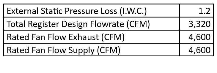
Figures 9, 10, and 11 show a spreadsheet-based calculation example for determining leakage allowance for a test at rough-in. Figure 9 illustrates a way to determine total register design flow rate. Figure 10 shows the rated fan flow and other design data, and Figure 11 shows the leakage allowance calculation.

Source
Source

Source
Duct Test Air Leakage Limit at Final
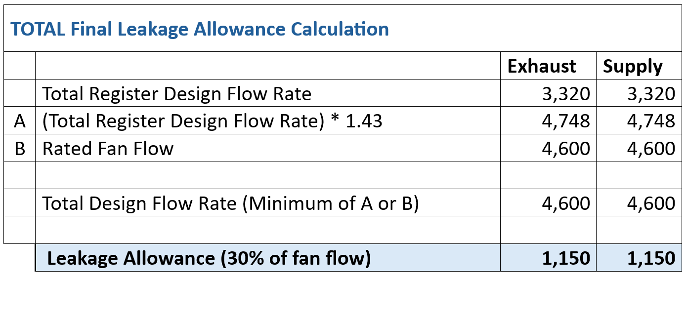
For a final test, the logic is the same as for the calculation at rough-in, but the limit is 30% of the total design flow rate to recognize the extra leakage introduced when installing registers and sealing to the sheetrock.
For the determination of the leakage allowance for a final leakage test of a complete duct system, first determine the total design flow rate as the lesser of values A or B below:
- (Total Register Design Flow Rate) x (1.43)
- Rated Fan Flow
To calculate the leakage allowance, multiply the lesser of values A or B above by 0.30.
Figure 12 shows an example leakage allowance calculation at final, based on the data shown in Figures 9 and 10.
Source
When using the total register design flow rate to calculate the total design flow rate, it can be useful to compare the sum of the register flow rates to the fan flow rate shown in the mechanical schedule (if shown). However, if the value in the mechanical schedule does not agree with the sum of the registers, the sum of the register flow rates should be used.
The total register design flow rate and the fan flow rate shown in the mechanical schedule might not agree for many reasons. There may be cases where a difference is meant to allow for a certain amount of duct leakage, or other cases where there may be a higher flow rate in the mechanical schedule if the designer showed the maximum flow rate for a specified variable rate fan instead of the required air flow at the registers. Planning for a high amount of duct leakage or specifying a fan with much more capacity than is needed are not good reasons for increasing a duct leakage allowance. There may also be cases where the ventilation design air flows of the areas served was changed, but the change was only reflected in the specified design air flows at the register or in the mechanical schedule and not in both locations.
Testing at 50 Pa instead of the Design or Operating Pressure
Commonly used duct leakage test fans have limitations on the amount of back pressure for accurate measurements. Accuracy is reduced at pressures above the back pressure limit. To avoid this reduced accuracy at high pressures, ENERGY STAR allows testing duct leakage at 50 Pa, but the result of a test at 50 Pa needs to be converted based on the actual design or operating pressure. The following version of the power law flow equation is used to convert the test result:
(Airflow at Design or Operating Pressure) = (Measured Airflow at 50 Pa) / [(50 Pa / Design or Operating Pressure) ^ (0.65)]
When planning for a test, the leakage allowance at 50 Pa can be calculated per this variation of the power law flow equation.
(Leakage Allowance at 50 Pa) = (Leakage Allowance at Design or Operating Pressure) / [((Design or Operating Pressure) / 50 Pa) ^ (0.65)]
Figure 13 illustrates how these calculations could be put into practice, based on the leakage allowance results from Figure 12.

Source
Test Reports at Other Test Pressures
When receiving an air leakage report from an aerosol sealant contractor in which the test result is not reported at the design pressure or operating pressure or 50 Pa, a more generalized version of the power law flow equation can be used to convert between any reported test pressure and the design or operating pressure:
(Airflow at Design or Operating Pressure) = (Measured Airflow at Test Pressure) / [(Test Pressure / Design or Operating Pressure) ^ (0.65)]
The leakage allowance at an anticipated test pressure other than 50 Pa can be determined this way as well.
(Leakage Allowance at Test Pressure) = (Leakage Allowance at Design or Operating Pressure) / [((Design or Operating Pressure) / Test Pressure) ^ (0.65)]
These equations may also be useful if the test pressure was not 50 Pa or the design pressure for some other reason. For example, if the test pressure was based on a specified design pressure, but later, the measured operating pressure was different from the design pressure, the test result at the operating pressure could be calculated this way. If the specified design pressure was much higher than the measured operating pressure, then the result at the measured operating pressure could be a lower value which more easily meets the specified leakage allowance.
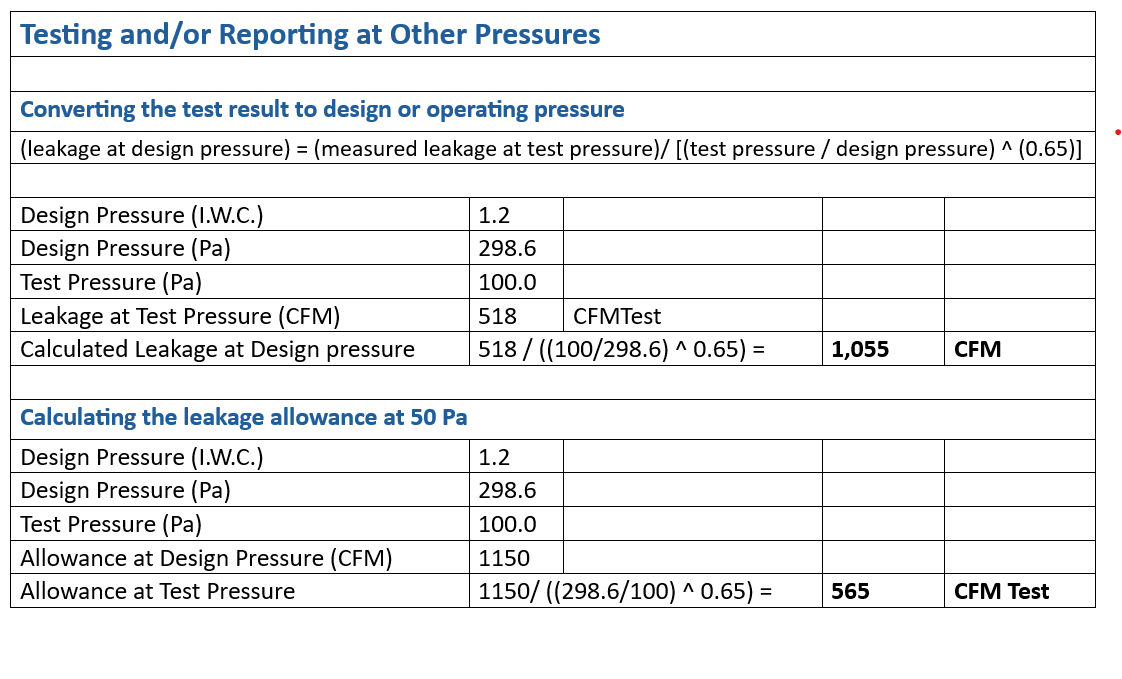
Note that these generalized power law flow equation calculations are helpfully built into the “ENERGY STAR MFNC Multifamily Workbook.” However, users should be cautioned using this workbook calculation in versions up to V1 Rev 04.02. These calculations in the V1 Rev 04.02 version and earlier only work properly for a test at 50 Pa or the nominal test pressure. Entering test flow and pressure at other pressures could indicate that the test passed, when in fact it should not have passed. Instead, the calculations should be performed externally if the test pressure was not exactly 50 Pa or the nominal test pressure.
Figure 14 illustrates how these calculations could be put into practice if the rater chose 100 Pa to be the test pressure. The leakage allowance used in the calculation is based on Figure 12.
Source
It should also be noted that in the power law flow equations above, a default flow exponent of 0.65 is used. Alternatively, for greater accuracy in these conversion equations, the flow exponent can be empirically determined by running the leakage test as a multipoint air leakage test per ASTM E779. This is not common practice, but can be done if necessary to arrive at a more project specific exponent.
Leakage Allowance when Testing a Portion of a Total Duct System
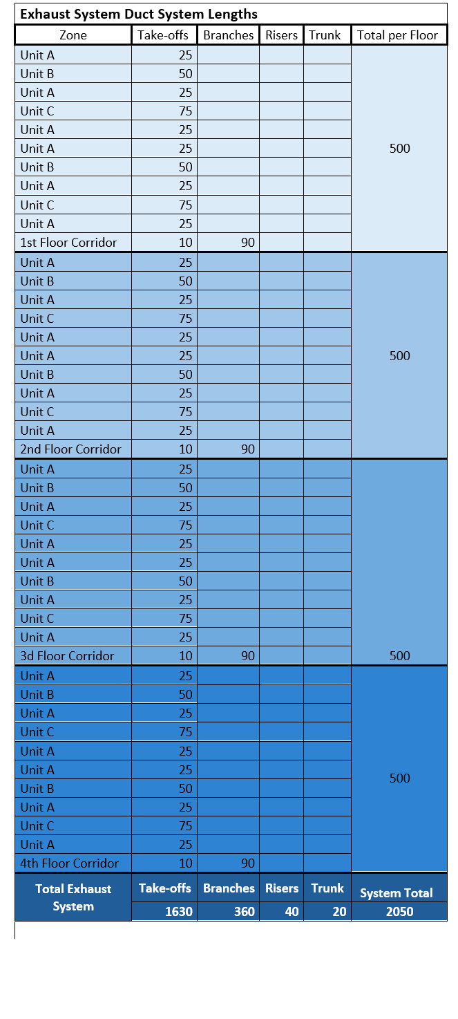
When testing a portion of a duct system, the leakage allowance for the test needs to be reduced according to the length of duct tested compared to the total duct length of the duct system.
These lengths can be calculated using duct distribution plans on HVAC floor plans and building sections.
If duct distribution plans are not available, then floor plans should be marked up with duct locations and duct length measurements.
The reduction in the duct leakage allowance is a factor equal to the total length of the ducts that were tested divided by the total length of all of the ducts in that duct system.
Reduction Factor = (Length of Duct Tested) / (Length of Total Duct System)
To find the reduced leakage allowance for the portion of ducts tested, multiply the leakage allowance determined for the entire duct system by this reduction factor.
Reduced Duct Leakage Allowance = (Reduction Factor) x (Leakage Allowance for Total Duct System)
Figures 15 and 16 show a spreadsheet-based calculation example for determining leakage allowance when testing only a portion of a duct system. Figure 15 tabulates duct lengths, and Figure 16 shows calculation details.
Source

Source
Test Equipment
Test equipment should include the following:
- a calibrated duct tester fan kit with long hoses (often at least 50 ft or even much longer depending on where reference pressures will be taken) and a static pressure probe
- a calibrated 2-channel manometer (a differential pressure gauge)
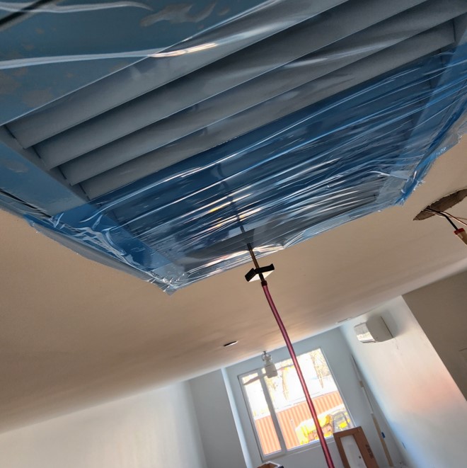
- tape or re-usable covers and an A-frame step ladder to seal ceiling registers
- extension cords as needed for the duct test location
- air thermometer.
Optional equipment that can be helpful includes the following:
- a data acquisition system to monitor remote pressures of multiple manometers
- a hand-held fogger or a theatrical fog machine for air leakage diagnostics when looking for the location of leaks (see the Success tab for more information).
Test Procedure
The ENERGY STAR Multifamily New Construction National Rater Field Checklist points to the RESNET Guidelines for Multifamily Energy Ratings for its air leakage test procedure.
These RESNET Guidelines reference ANSI / RESNET / ICC Standard 380 which is meant for set up and operation of a duct test of residential dwelling unit heating and cooling duct systems. The RESNET Guidelines elaborate on key differences between a standard duct test of dwelling unit duct systems and tests of central ventilation duct systems.
The basic steps of the standard test are as follows.
- Make sure all HVAC Equipment connected to the tested ductwork is turned off.
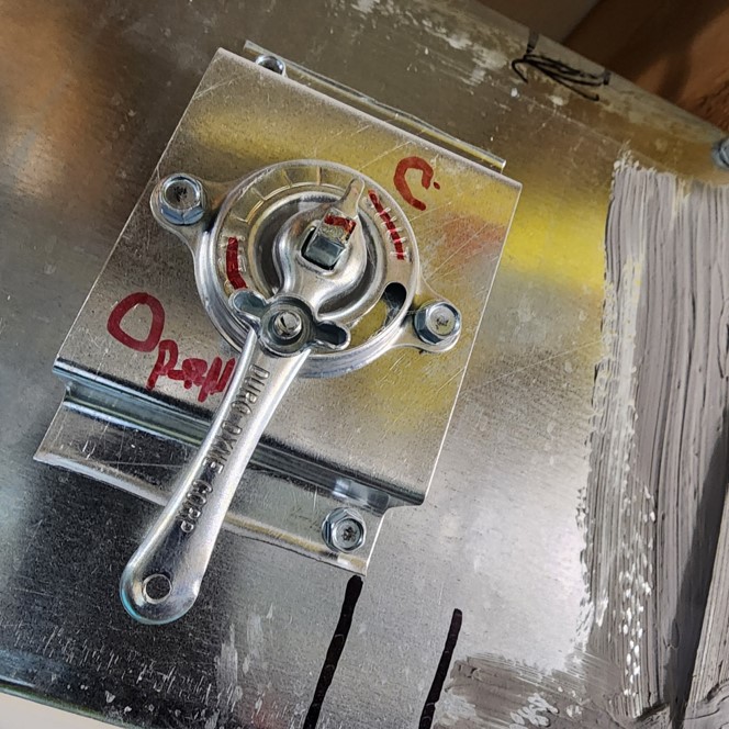
- Make sure fire dampers and volume dampers are in the fully open position.
- Seal registers.
- Set up test equipment.
- Measure baseline pressures.
- Run test.
- Investigate and perform necessary diagnostics.
- Record results.
For the basics of total duct leakage testing see the BASC Guide, Total Duct Leakage Tests.
Duct Test Fan Attachment Location
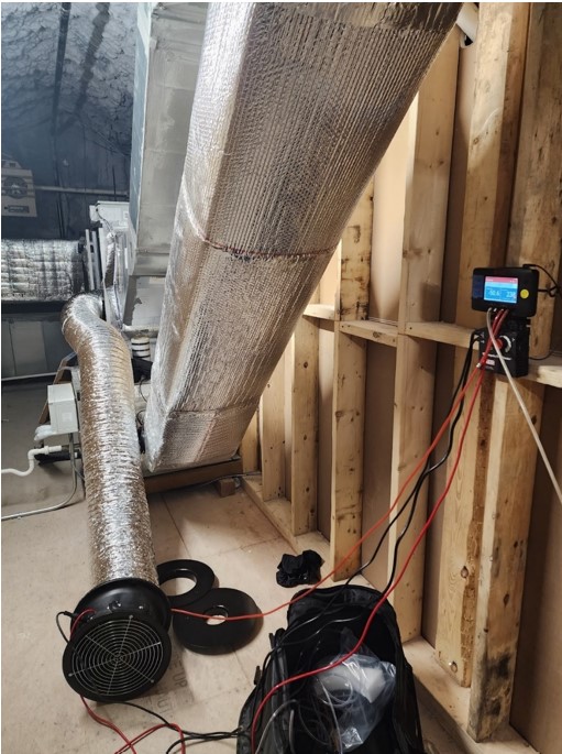
The duct tester fan needs to be attached to the duct system at a portion of the ductwork which is large enough to accommodate the total airflow of a passing duct test without any significant pressure drop in the duct system. Attachment at terminal registers will typically not work for this, because they are typically too small for the total flow of the duct test. Instead, the duct tester ought to be attached to the area of the duct work with the largest cross-section area. This attachment location should be as close to the ventilation fan as possible, often inside the air handling cabinet.
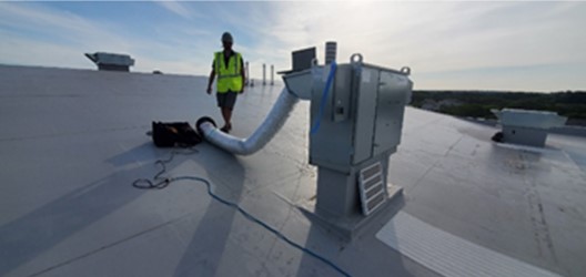
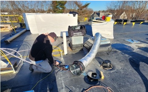
For a final test of an exhaust-only ventilation system with a mushroom-type rooftop fan, the fan is removed from the curb and the duct test fan attached to the curb below the mushroom fan. In this case, the test operator should craft a transition plate to attach to the duct work as it exits the roof top curb. The transition plate should have an opening for the attachment of a duct tester’s flexible extension duct. Figure 17 shows a rooftop duct test set-up showing this configuration.
Source
Figure 18 shows a duct test set-up at an ERV located in an attic mechanical area. In this case, the test fan is attached inside the cabinet of the ERV to the opening of the ERV where the ductwork to the interior begins. Figure 19 shows the same scenario. This type of arrangement can also be done on a rooftop, when a rooftop ERV or HRV has already been installed.
Source

Source
Test Pressure Monitoring Location
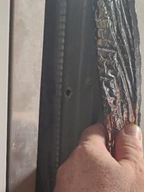
The test pressure for the test should be monitored in a straight section of ductwork where turbulent air flow is minimal. Whenever possible, it should be at least 3 duct diameters downstream of any turns or branches in the ductwork. The duct pressure hose from the manometer should terminate in a static pressure probe which is pointed directly into the air flow (Figures 20 and 21).

Source
Source
Duct Test Baseline Pressure
Wind and stack effect pressures necessitate baseline pressure measurements for the sake of determining the induced pressure of the test and for determining the uniformity of the distribution of the test pressure. Stack effect in taller buildings when the indoor and outdoor temperatures are very different can constitute a considerable portion of the test pressure. Wind effect can also be considerable on large buildings. This is a larger concern when testing at 50 Pa instead of a much higher design or average operating pressure.
Choice of Test Pressure
When testing commercial ductwork, RESNET guidelines advise that the duct test pressure be at least 50 Pa instead of 25 Pa. (25 Pa is the standard test pressure for heating and cooling ducts in dwelling units and single-family homes). This is because most commercial ductwork operates at much higher static pressures than typical residential ductwork.
Where performing the central exhaust duct leakage test for ENERGY STAR MFNC compliance, the test pressure may be 50 Pa or the design/operating pressure. However, when the test pressure is 50 Pa, or any other test pressure other than the design/operating pressure, the duct test result needs to be adjusted to the duct system operating pressure, as described in detail in the previous section titled “Testing at 50 Pa Instead of the Nominal Test Pressure.”
Best practice is to test at the design operating pressure or the average operating pressure. However, when the duct testing equipment is not accurate at these elevated pressures, a lower pressure can be used with the caveat that the extrapolation of the result to the design operating pressure or the average operating pressure will lead to additional error in the result.
Pressure Distribution Check
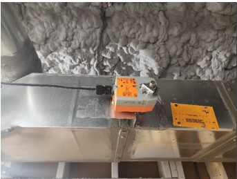
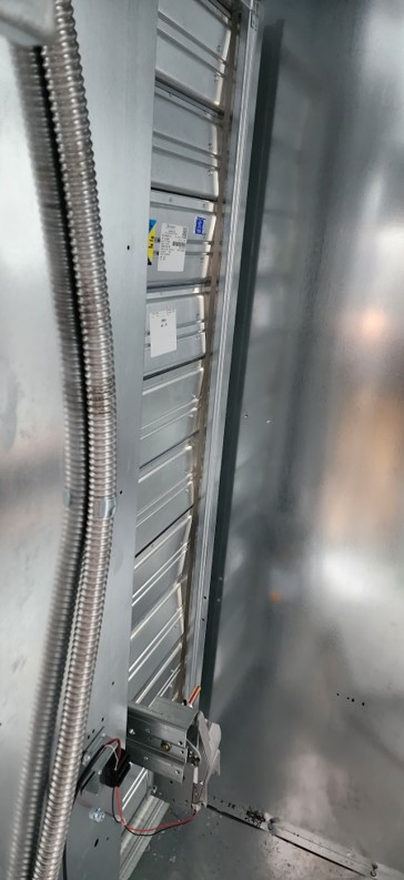
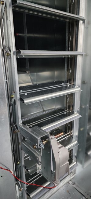
It is important to ensure that all dampers are fully open during the test by measuring the pressure at registers on the far side of all dampers in the duct system. Otherwise, a test may show a false result. Even partially closed fire dampers or volume dampers may create a pressure drop and result in a lack of uniform pressure distribution during the test (Figure 22). This can reduce the apparent leakage and make the ducts appear tighter than they really are.

Source
Simply observing actuator position from outside the duct is not a reliable way to determine damper position. Instead, the pressure downstream of the damper should always be checked (Figure 23).
Source
When the test is operating and the monitored pressure of the test is at the target pressure at the primary reference pressure location near the test fan, the pressure of the rest of the duct system should be checked in other parts of the duct system to ensure that a uniform pressure distribution has been achieved (Figures 24 and 25).

Source

Source
When checking uniform pressure distribution, a baseline adjusted pressure measurement at the distributed points is a more accurate determination of uniform pressure distribution than an absolute pressure measurement. Due to stack effect, wind effect, or other mechanical system pressures, there may be significant differences in absolute pressure measurements at different parts of a duct system both when the system is off and during the test. A baseline adjusted measurement accounts for these differences.
A baseline adjusted measurement requires 2 measurements at each location: a baseline measurement taken when the system is all off and sealed for the test and a subsequent measure at the test pressure. The baseline adjusted pressure is the difference between the measurement at the test pressure and the baseline pressure. An absolute pressure measurement is any single pressure measurement which is unadjusted by a baseline.
For an accurate test, the baseline adjusted pressures for all locations should be within +/- 10% of each other.
Savvy practitioners will bring multiple manometers and set these up at distributed locations in the duct system and monitor each manometer throughout testing.
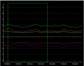
Even more savvy practitioners will connect all manometers to a data acquisition system to show and report the pressures at all locations alongside the monitoring of the duct leakage test (Figure 26). Monitoring many manometers simultaneously can greatly assist with test operation including diagnostics and reporting.
Source
Accounting for baseline pressures and pressure distribution checks as described above will result in the most accurate and reproducible results. Note that this pressure distribution check is not explicitly included in ENERGY STAR requirements, but ENERGY STAR MFNC does assume that the entire system is being pressurized to the test pressure, so, for accurate and reproducible test results, some method of ensuring an even distribution of induced pressure results should be practiced.
What party Performs the Test
For ENERGY STAR MFNC compliance, the ENERGY STAR MFNC rater will usually perform this test.
HVAC contractors who are installing the duct system can certainly do this test as a self-check in preparation for balancing and in preparation for official program compliance testing by a third party.
Contractors of aerosolized acrylic air sealing systems naturally perform a version of this test before, during, and after the application of the air sealing system. The reports from one of these contractors may be acceptable to meet the verification requirement for ENERGY STAR MFNC compliance. Contractors should follow all of the best practices from this guide including pressure distribution checking and include documentation of all of this information with their report so that an ENERGY STAR MFNC rater or other third-party verifier or official will be more likely to accept the test report.
Reporting Results
Determination of the leakage limit and test pressure should include the following details:
- nominal test pressure, including whether the pressure is positive or negative, and whether the pressure used is the design pressure or a measurement of operating pressure
- length of ducts tested, shown and dimensioned on floor plans
- total length of ducts, shown and dimensioned on floor plans
- state of construction (rough/final)
- total design flow rate calculation
- leakage allowance calculation, including adjustment using the power law flow equation for testing/reporting at a pressure other than the target test pressure.
Test set up and operation should be thoroughly described including:
- location of the test fan and primary pressure monitoring location
- location and position of dampers throughout the tested system
- location of pressure distribution checks during the test (recommended but not required by ENERGY STAR MFNC)
- baseline pressure and test pressure at the primary pressure monitoring location
- pressure measurements at pressure distribution check locations (recommended but not required by ENERGY STAR MFNC)
- time period of the Baseline pressure and test pressure measurements
- indoor and outdoor air temperature and wind conditions (when any portion of the tested duct or the test fan itself is exposed to the exterior).
Test results should include the following:
- detailed measured airflow rates and test pressures for each time period recorded
- the final averaged result and an estimate of the error of the test. For tests performed at a single test pressure, the reported error should be the average deviation of the repeated test measurements. Note that calculating and reporting error is a best practice which is not required by ENERGY STAR MFNC.
Ensuring Success
Key aspects of a successful testing plan include careful consideration of the timing of the tests.
Early testing of a portion of the duct system is helpful for ensuring good duct sealing practices are used from the start of the duct sealing work. This type of testing should be performed while duct sealing contractors are present and available to do additional sealing if the test is not passing the specified leakage allowance.
In order to help the contractors find and seal duct leakage locations, a theatrical fog machine producing dense fog can be used to blow fog into a duct system through the duct testing fan. The fog will come out of leaks and quickly make the leaks obvious (Figure 1). This will also help observers to visualize the reality of the duct leakage measurements.

Source
To avoid fouling the fan motor and pressure taps, use the test fan without rings and point the fog stream toward the outer edge of the test fan opening (Figure 2).

Source
Testing an entire system as soon as it is complete is most helpful at making sure all parts of the system were adequately sealed. Doing this before sheetrock as much as possible will make it much easier to find and fix leaks.
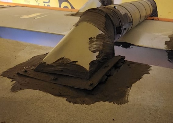
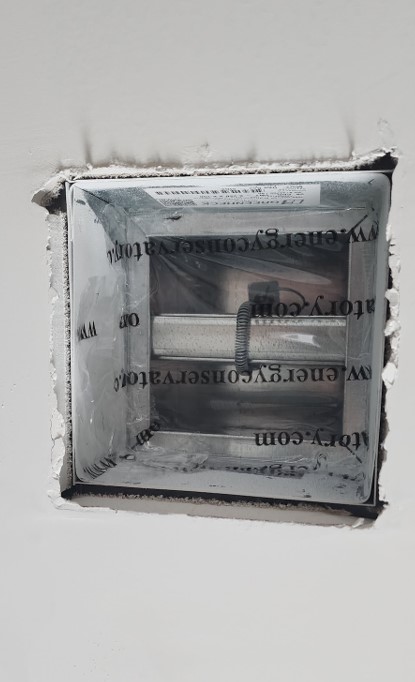
Correcting leakage after a test at final is possible. However, if manual efforts are not successful, this may require use of aerosolized duct sealant. When aerosolized duct sealant is used, be sure to cover and protect sensitive dampers such as CAR (Constant Airflow Regulator) dampers and any other components in the duct work that may be fouled by deposition of the aerosolized sealant (Figure 3).

Source
Region
No climate specific guidance is needed for the test procedures in this guide, however a project in which the test equipment must be attached to ductwork in an exposed location will need planning for appropriate conditions with respect to extreme temperatures, wind, and precipitation.
Training
Right and Wrong Images
Source
Source

Source

Source

Source
Source
Source

Source

Source
Source

Source

Source
Source
Source
Source
Retrofit
The information in this guide applies to new and existing central exhaust ventilation systems and other types of central ventilation systems in multifamily buildings.
For an overview of improving central exhaust systems in existing buildings, see the fact sheet “Improving Ventilation in Existing or New Buildings with Central Roof Exhaust” from the National Center for Healthy Housing.
For more depth on the overall subject of retrofitting central exhaust ventilation systems see “Multifamily Ventilation Retrofit Strategies”, by Building Science Corporation.
For a broad look at the overall effectiveness of a variety of ventilation systems in existing buildings, see the BASC guide “Pre-Retrofit Assessment of Ventilation Systems”
More Info
References and Resources
*For non-dated media, such as websites, the date listed is the date accessed.
Contributors to this Guide
The following authors and organizations contributed to the content in this Guide.
Michael A. Browne, Advanced Building Analysis, LLC
Questions? Comments? Contact our webmaster.