
Condensing HVAC has Corrosion-Resistant Condensate Drain Pan

    Scope
    Scope Images
    Image
    The drain pans sit below the cooling coil to catch condensate and direct it to a drain line
    Scope

    For each condensate-producing HVAC component, install a corrosion-resistant drain pan under the equipment.

    • Install a secondary drain pan of corrosion-resistant galvanized steel or durable plastic under HVAC equipment that has an evaporator coil.
    • Install auxiliary drain lines and drain pans as required by code.

    See the Compliance Tab for related codes and standards requirements and criteria to meet national programs such as DOE’s Zero Energy Ready Home programENERGY STAR Single-Family New Homes, and Indoor airPLUS.

    Description
    Description

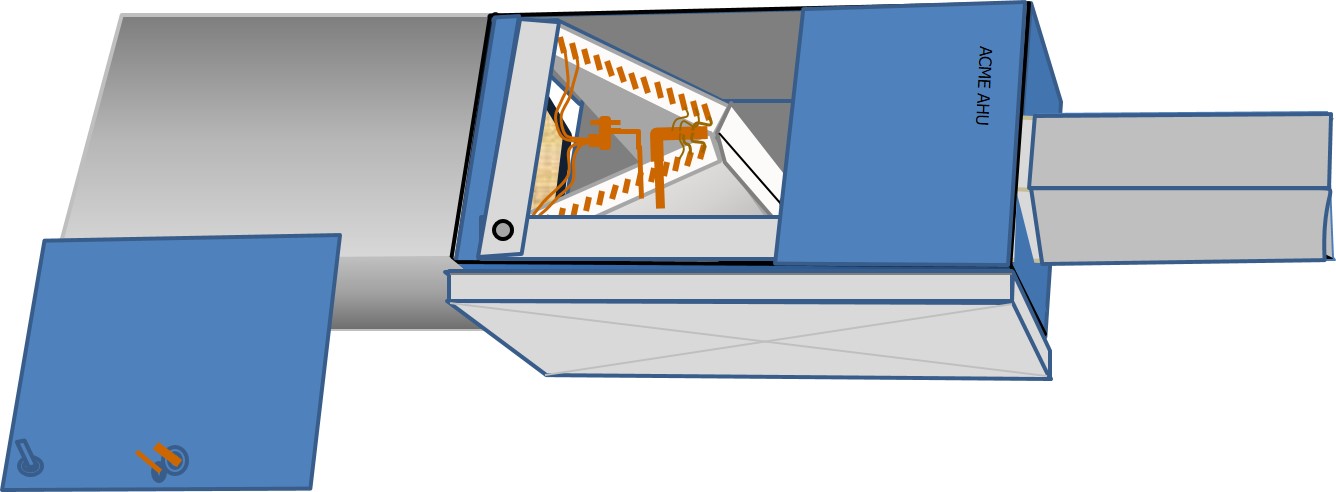
    As air passes through the cold evaporator coil of an air conditioner or heat pump, its temperature is lowered below the saturation point. The moisture condenses out and falls as liquid into a collector positioned under the coil. This collector is a gutter-like device or shallow pan, which manufacturers call the primary condensate drain pan or just the condensate pan. The objective of the condensate drain pan is to thoroughly collect and then direct the condensate water to a condensate drain (Figure 1). While older HVAC systems used steel pans, today the major equipment makers use different plastic materials to build a smooth-surfaced, rust-proof condensate pan. To assist drainage and prevent pooling, some manufacturers slope the base of the pan toward the drain openings (KC Hart and Company).

    The drain pans sit below the cooling coil to catch condensate and direct it to a drain line.
    Figure 1. The drain pans sit below the cooling coil to catch condensate and direct it to a drain line. (Source: Calcs Plus.)


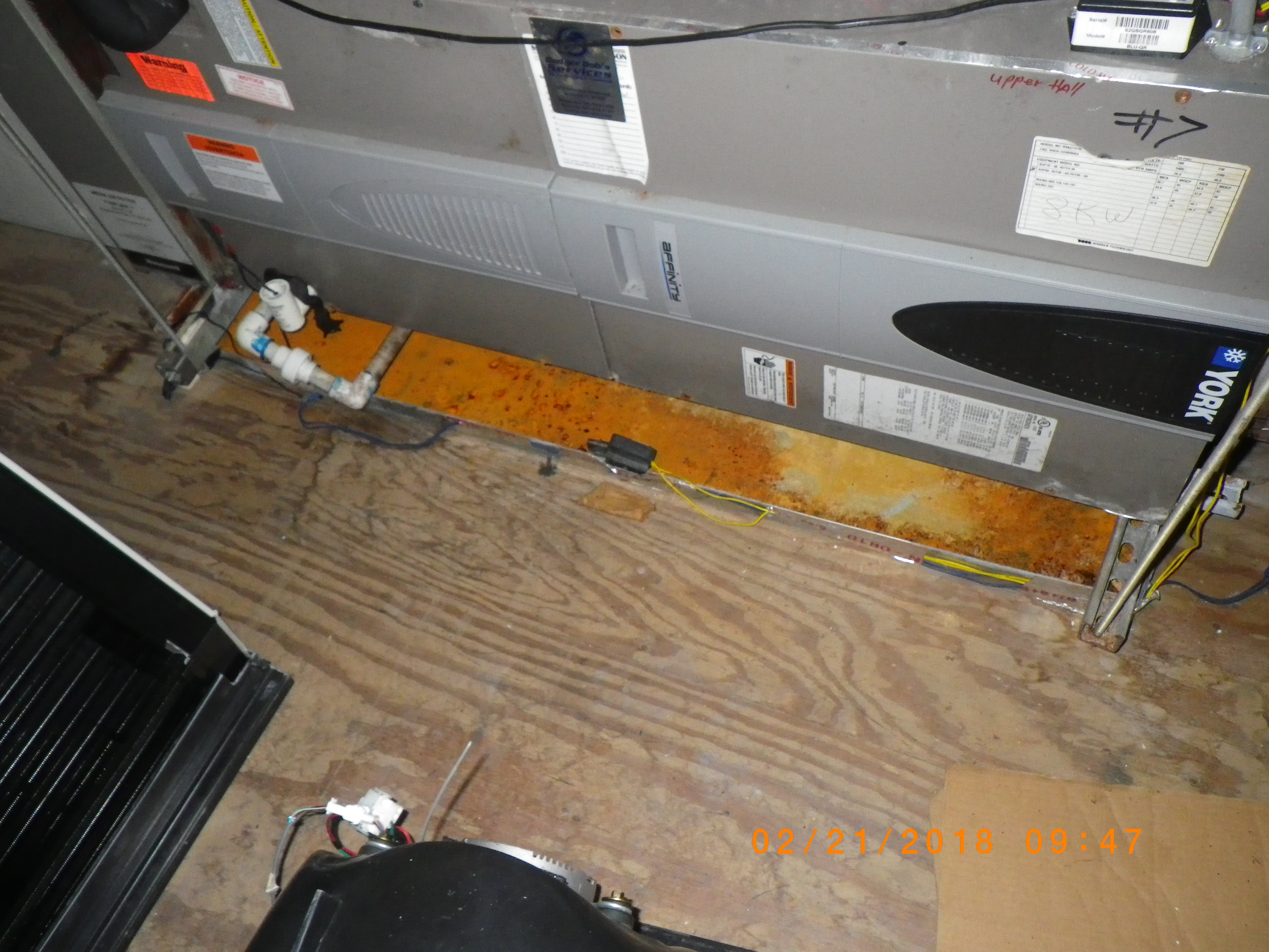
    As the pan fills, it must continually drain to prevent it from overflowing and causing damage to the equipment and to the surroundings. Clogged drain lines and overflowing drain pans from equipment located in attics, basements, and closets can go undetected long enough to cause severe water damage in ceilings, floors, and walls. Poorly draining pans can collect stagnant water that can become a breeding ground for algae and bacteria (see KC Hart and Company). The drain pan should be checked periodically to look for stagnant water, blocked drain lines, overflowing pans, or corroded and leaking pans (Figure 2).

    Metal drain pans under HVAC equipment can corrode over time, especially in humid environments.
    Figure 2. Metal drain pans under HVAC equipment can corrode over time, especially in humid environments. (Source: Calcs Plus.)


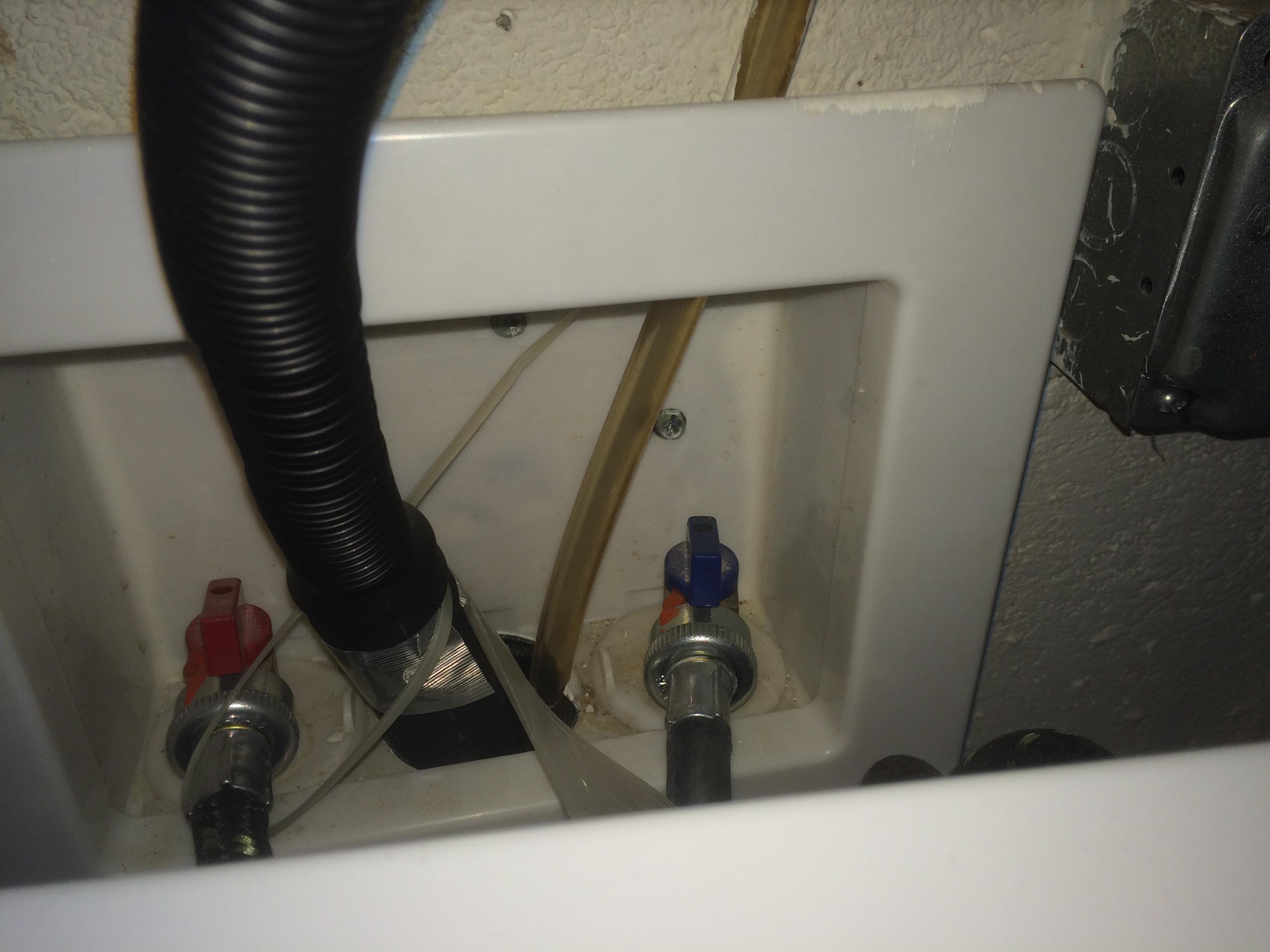
    The International Residential Code requires that evaporator coils have a secondary drain pan if blockage of the drain pipe and overflow of the primary drain pan would cause damage to building components. (See the Compliance tab for detailed requirements.) The second drain pan should discharge to a conspicuous spot to alert occupants in the event of blockage of the drain pipe. For cooling systems installed in the attic, some installers will have this secondary drain discharge over a window so that it is more noticeable if it should start dripping. No trap should be installed on the auxiliary pan drain pipe. A separate overflow drain line should also be connected to the primary drain pan. This drain line, which is connected to a higher fitting on the primary condensate pan, should also drain to a conspicuous spot. Code requires that an additional auxiliary drain pan without a separate drain line be installed under the coils on which condensation will occur. This pan should be equipped with a water-level detection device (also called a float switch) that will shut off the equipment if the pan is in danger of overflowing (Figure 3). The primary drain line should also be equipped with a water-level detection device that will shut off the equipment in the event that the primary drain is blocked. Code requires that a water-level detection device should also be installed on equipment that is not required to have a secondary or auxiliary drain pan.

    The HVAC equipment’s condensate drain pan is equipped with a water-level detection device that will shut off the equipment if the water level pan in the pan gets too high.
    Figure 3. The HVAC equipment’s condensate drain pan is equipped with a water-level detection device that will shut off the equipment if the water level pan in the pan gets too high. (Source: Calcs Plus.)


    Although not required by codes, such water-level detection devices can also be equipped with an alarm to alert occupants that the equipment has been shut off due to high water levels in the drain pan.

    Emergency pans should be made of a rust-resistant material such as plastic or galvanized steel. They should extend beyond the air handler or coil box by 3 inches or more on all sides. If the coil is attached to a high-efficiency furnace without condensate protection, this should be taken into consideration when sizing and placing a pan under the equipment. The condensate produced by the furnace can damage the building if it overflows during the heating season. The IMC/IRC requires the auxiliary pan to be a minimum of 1½ inches deep. See the Compliance tab for more details on code requirements for drain pans and drain pipes.

    Blow-Through and Draw-Through Systems

    The evaporators of air conditioners and the indoor coils of heat pumps are installed so that a blower either pushes or pulls air over their cooling surfaces. When air is pushed across, putting the coil under positive pressure, it is considered a blow-through or positive pressure system. When air is pulled across the coil, it is a draw-through or negative pressure system. Many air handlers used with heat pumps or with modern AC cooling-only systems are draw-through systems. Blow-through systems are common when cooling coils are attached to a gas or oil furnace, as most furnace makers call for cooling coils to be placed downstream of the heat exchanger. Unless the furnace is listed and labeled safe to be downstream of a cooling coil (which is rare), passing cooled air over the heat exchanger will result in extensive corrosion of the furnace, premature failure of the heat exchanger, and moisture damage to the surroundings (KC Hart and Company).

    Trapping

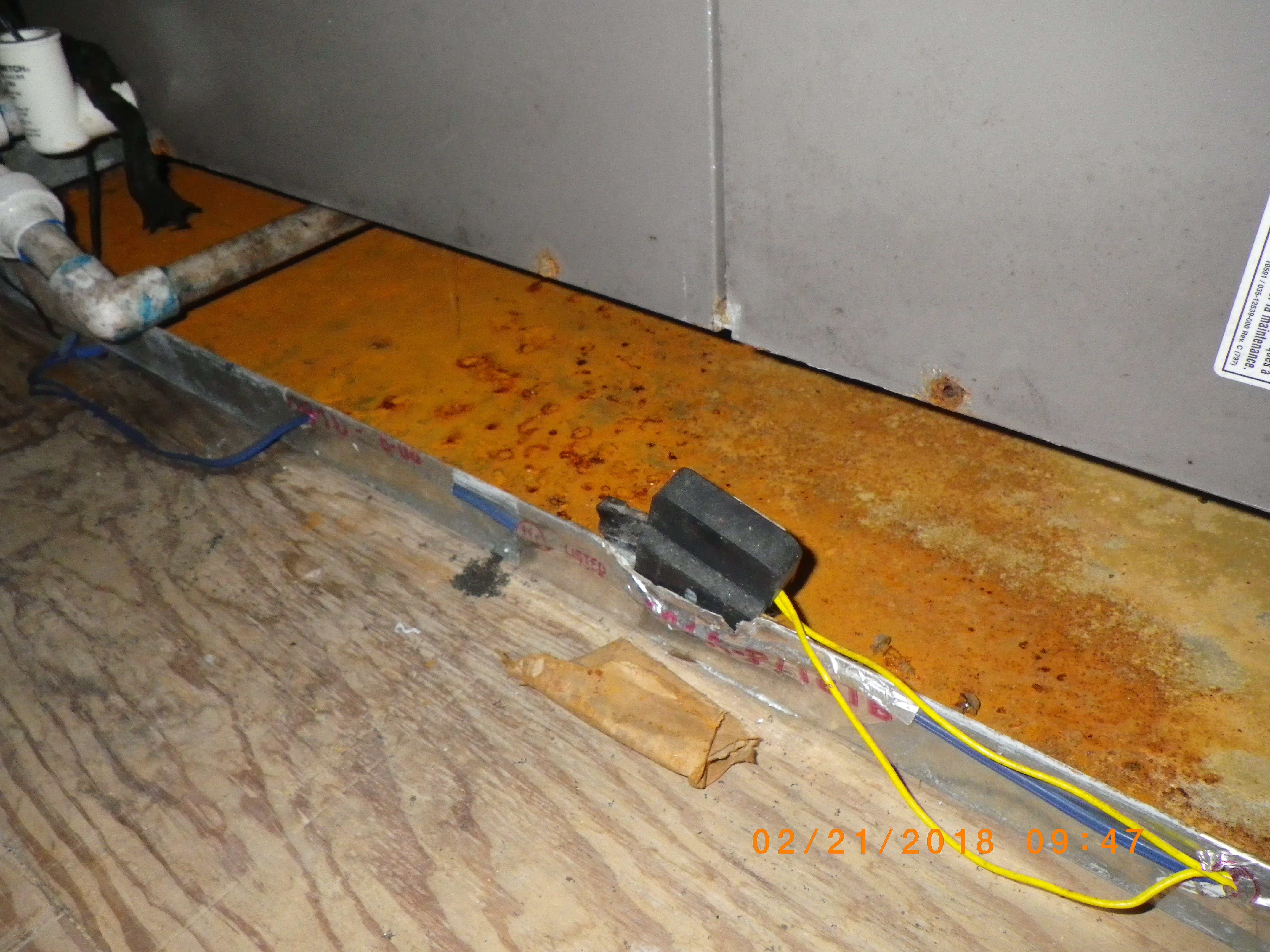
    The drain line should be equipped with a trap, a u-shaped bend in the pipe that is either factory-made or site fashioned and has a minimum drop of 2 inches from the pan, plus 2 inches more for the trap seal, and a clean-out with a removable cap (Figure 4). The primary purpose of a condensate trap is to prevent air from moving in or out of the coil box or air handler during operation. Traps must be installed in a manner that will stop the air from passing through, but still allow the condensate to drain from the condensate pan. Failure to install a trap on a blow-through system can reduce system efficiency but in most cases the pan will still drain. A poorly functioning trap on a draw-through system will not only cause system inefficiency because it can pull in hot attic air, but the air being sucked through the drainpipe can prevent the pan from draining, causing it to run over.  Without proper trapping, air pulled back into the equipment can lift the water up from the condensate pan and spray it onto nearby components which can cause corrosion of the equipment and if the condensate pan is contaminated, this can also become a health issue. For more on traps please see KC Hart and Company.

    The drain pipe should include a trap and a clean-out with a removable cap.
    Figure 4. The drain pipe should include a trap and a clean-out with a removable cap. (Source: KC Hart and Company.)


    Drain Pipe

    Over the years, PVC pipe has become the condensate drain material of choice for residential applications in many areas. The International Residential Code also allows cast iron, galvanized steel, copper, polybutylene, polyethylene, ABS, and CPVC to be used. Although it is rare to see plastic pipe insulated, sometimes it does need to be wrapped close to the equipment where the coolest water is exiting the pan to prevent it from sweating. With metal drains such as copper, failure to insulate the pipe and trap can almost guarantee a complete soaking of the surrounding surfaces from the secondary condensation generated by the cool water flowing through the drain pipe (KC Hart and Company).

    According to the International Residential Code, the pipe should not be less than ¾ inches in diameter and should not be decreased in size from its connection at the condensate pan to the point where the condensate water finally clears the pipe. Drains should be installed pitched toward the discharge point. Manufacturers often recommend a drop of ¼-inch per foot; the code allows for 1/8-inch per foot.

    Condensate Pumps

    A condensate pump is used when a gravity drain is impractical or impossible to install. They are common on some basement-installed systems or where cooling has been added to an existing heating system located within the interior walls of a slab-foundation home. The plumbing from the cooling coil to the condensate pump reservoir or tank should be installed with traps and float switches as if the coil was draining like a typical gravity drain.

    With condensate pumps, the cooling coil drains to the pump’s reservoir. As the water level rises, a float switch turns on the pump and water is pumped from the reservoir, usually through flexible plastic tubing, to a safe area. Should the pump fail or should the discharge line become blocked, a second switch will open a low-voltage circuit that shuts down the air conditioner and can even be wired to set off an alarm.

    Proper Disposal of Condensate

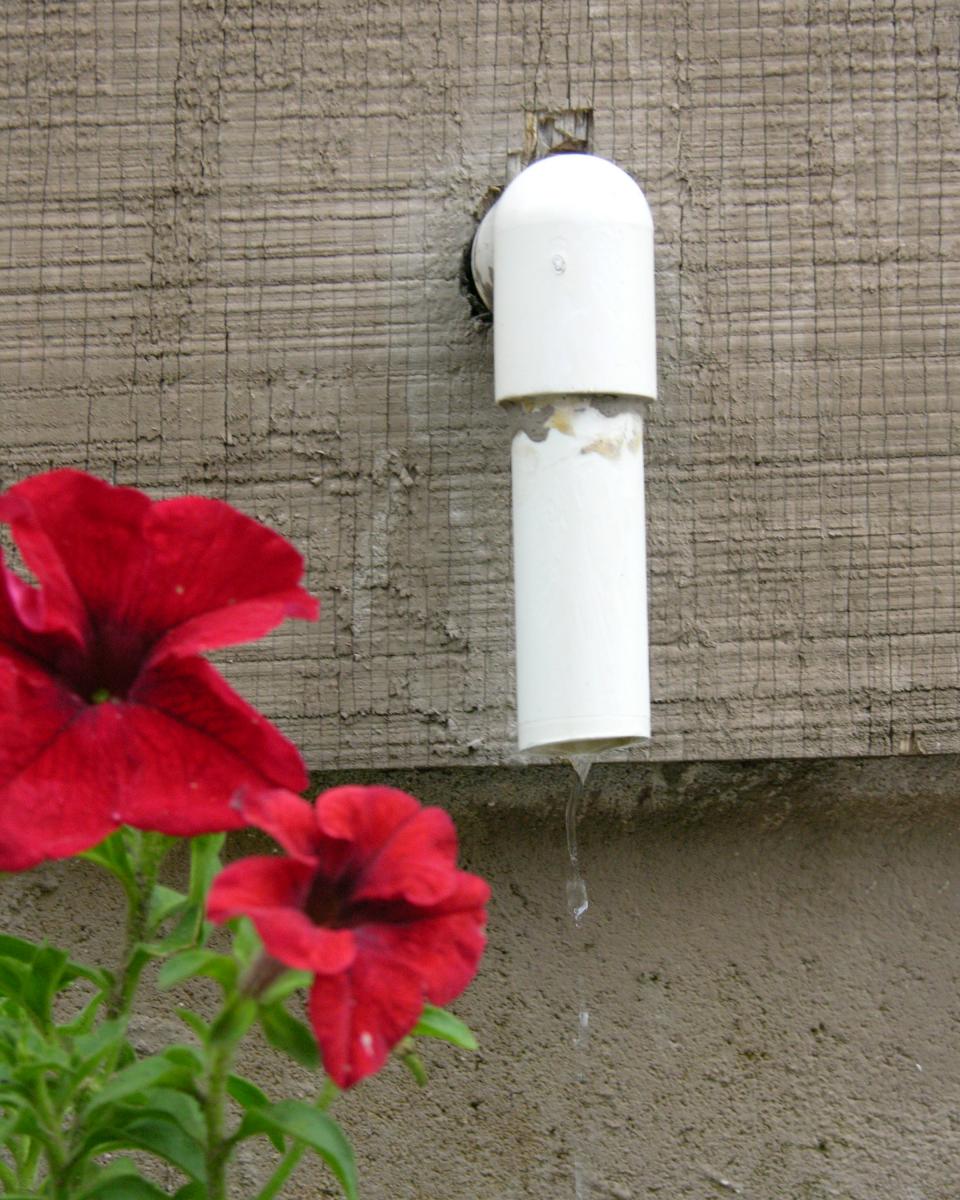
    According to the International Residential Code, “Condensate shall not discharge into a street, alley, or other area where it would cause a nuisance.” With residential properties, it is commonplace to discharge condensate at the exterior of the house, generally near the foundation (Figure 5). Use a splash pan to direct this water away from the foundation.

    Follow local codes to determine the acceptability of directing the condensate drains into the domestic plumbing system. If the drain pipe is connected to a shared drainage system, a backflow prevention valve should be included.

    Note: Unlike condensate from air conditioners and heat pumps, condensate from condensing furnaces and boilers can be highly acidic. Local code requirements should be followed regarding disposal of the condensate, either to the outdoors or to the sewer (Figure 6), and pretreatment of condensate, if required, before disposal to the sewer.

    Condensate from air conditioners can be discharged near the house; use a splash pan to direct the condensate away from the foundation.
    Figure 5. Condensate from air conditioners can be discharged near the house; use a splash pan to direct the condensate away from the foundation. (Source: KC Hart and Company.)


    The condensate line (amber-colored plastic tube) from the high-efficiency furnace drains into the sewer via the same drain pipe as the clothes washer.
    Figure 6. The condensate line (amber-colored plastic tube) from the high-efficiency furnace drains into the sewer via the same drain pipe as the clothes washer. (Source: PNNL.)


    Success
    Ensuring Success

    Inspect to ensure that the cooling system has a secondary drain pan under the evaporator, that the system has a secondary drain line, and that the cooling coil is downstream of the heat exchanger in blow-through gas- or oil-furnace-based heating and cooling systems.

    Inspect to ensure that the primary and secondary drain connections are made to the two lowest fittings on the air handler or coil box.

    Climate
    Climate

    No climate-specific guidance applies.

    CAD
    CAD Files
    Front view of horizontal air handler showing condensate drain pans and drain lines
    Front view of horizontal air handler showing condensate drain pans and drain lines
    Download: DWG PDF
    Front view of horizontal air handler showing outdoor air intake, dampers, supply and return, emergency drain pan, and drain overflow safety cut off switch
    Front view of horizontal air handler showing outdoor air intake, dampers, supply and return, emergency drain pan, and drain overflow safety cut off switch
    Download: DWG PDF
    Front view of horizontal air handler showing outdoor air intake, dampers, supply and return, and condensate drain pans, drain pipe and trap, and drain overflow safety cut off switch
    Front view of horizontal air handler showing outdoor air intake, dampers, supply and return, and condensate drain pans, drain pipe and trap, and drain overflow safety cut off switch
    Download: DWG PDF
    Front view of vertical air handler condensate disposal and controls
    Front view of vertical air handler condensate disposal and controls
    Download: DWG PDF
    Front view of vertical air handler condensate disposal and controls
    Front view of vertical air handler condensate disposal and controls
    Download: DWG PDF
    Compliance

    Compliance

    The Compliance tab contains both program and code information. Code language is excerpted and summarized below. For exact code language, refer to the applicable code, which may require purchase from the publisher. While we continually update our database, links may have changed since posting. Please contact our webmaster if you find broken links.


    ENERGY STAR Single-Family New Homes, Version 3/3.1 (Rev. 11)

    National Water Management System Builder Requirements

    4. Water-Managed Building Materials.
    4.6 For each condensate-producing HVAC component, corrosion-resistant drain pan (e.g., galvanized steel, plastic) included that drains to a conspicuous point of disposal in case of blockage. Backflow prevention valve included if connected to a shared drainage system.

    Please see the ENERGY STAR Single-Family New Homes Implementation Timeline for the program version and revision currently applicable in your state.


    2009, 2012, 20152018, and 2021 International Residential Code (IRC)

    M1411.3 Condensate disposal

    Condensate from cooling coils and evaporators shall be conveyed from the drain pan outlet to an approved place of disposal. Such piping shall maintain a minimum horizontal slope in the direction of discharge of not less than 1/8 unit vertical in 12 units horizontal (1% slope). Condensate shall not discharge into a street, alley or other area where it would cause a nuisance.

    M1411.3.1 Auxiliary and secondary drain systems

    In addition to the requirements of Section M1411.3, a secondary drain or auxiliary drain pan shall be required for each cooling or evaporator coil where damage to any building components will occur as a result of overflow from the equipment drain pan or stoppage in the condensate drain piping. Such piping shall maintain a minimum horizontal slope in the direction of discharge of not less than 1/8 unit vertical in 12 units horizontal (1% slope). Drain piping shall be not less than ¾-inch (19mm) nominal pipe size. One of the following methods shall be used:

    1. An auxiliary drain pan with a separate drain shall be installed under the coils on which condensation will occur. The auxiliary pan drain shall discharge to a conspicuous point of disposal to alert occupants in the event of a stoppage of the primary drain. The pan shall have a minimum depth of 1.5 inches (38 mm), shall be not less than 3 inches (76 mm) larger than the unit or the coil dimensions in width and length and shall be constructed of corrosion-resistant material. Galvanized sheet steel pans shall have a minimum thickness of not less than 0.0236-inch (0.6010 mm) (No 24 gage). Nonmetallic pans shall have a minimum thickness of not less than 0.0625 inch (1.6 mm).

    2. A separate overflow drain line shall be connected to the drain pan installed with the equipment. This overflow drain shall discharge to a conspicuous point of disposal to alert occupants in the event of a stoppage of the primary drain. The overflow drain line shall connect to the drain pan at a higher level than the primary drain connection.

    3. An auxiliary drain pan without a separate drain line shall be installed under the coils on which condensation will occur. This pan shall be equipped with a water level detection device conforming to UL 508 that will shut off the equipment served prior to overflow of the pan. The pan shall be equipped with a fitting to allow for drainage. The auxiliary drain pan shall be constructed in accordance with item 1 of this section.

    4. A water-level detection device conforming to UL 508 shall be installed that will shut off the equipment served in the event that the primary drain is blocked. The device shall be installed in the primary drain line, the overflow drain line, or the equipment-supplied drain pan, located at a point higher than the primary drain line connection and below the overflow rim of such pan.

    M1411.3.1.1 Water-Level Monitoring Devices.

    On down-flow units and other coils that do not have secondary drain or provisions to install a secondary or auxiliary drain pan, a water-level monitoring device shall be installed inside the primary drain pan. This device shall shut off the equipment served in the event that the primary drain becomes restricted. Devices shall not be installed in the drain line.

    M1411.3.2 Drain Pipe Materials and Sizes

    Components of the condensate disposal system shall be ?ABS, cast iron, copper, cross-linked polyethylene, CPVC, galvanized steel, PE-RT, polyethylene, polypropylene or PVC pipe or tubing. Components shall be selected for the pressure and temperature rating of the installation. Joints and connections shall be made in accordance with the applicable provisions of Chapter 30. Condensate waste and drain line size shall be not less than ¾-inch (19 mm) nominal diameter from the drain pan connection to the place of condensate disposal. Where the drain pipes from more than one unit are manifolded together for condensate drainage, the pipe or tubing shall be sized in accordance with an approved method.

    M1411.3.3 Drain Line Maintenance [added in 2015 IRC, subsequent sections are renumbered]

    Condensate drain lines shall be configured to permit the clearing of blockages and performance of maintenance without requiring the drain line to be cut.

    M1411.3.4 Appliances, Equipment, and Insulation in Pans

    Where appliances, equipment, or insulation are subject to water damage when auxiliary drain pans fill, those portions of the appliances, equipment, and insulation shall be installed above the flood level rim of the pan. Supports located inside of the pan to support the appliance or equipment shall be water resistant and approved.

    M1411.4 Condensate Pumps [added in 2015 IRC]

    Condensate pumps located in uninhabitable spaces, such as attics and crawl spaces, shall be connected to the appliance or equipment served such that when the pump fails, the appliance or equipment will be prevented from operating. Pumps shall be installed in accordance with the manufacturer’s instructions.

    M1411.5 Auxiliary drain pan

    Category IV condensing appliances shall have an auxiliary drain pan where damage to any building component will occur as a result of stoppage in the condensate drainage system. These pans shall be installed in accordance with the applicable provisions of Section M1411.3.

    Exception Fuel-fired appliances that automatically shut down operation in the event of a stoppage in the condensate drainage system.

    Retrofit:  2009, 2012, 2015, 2018,  and 2021 IRC

    Section R102.7.1 Additions, alterations, or repairs. Additions, alterations, renovations, or repairs shall conform to the provisions of this code, without requiring the unaltered portions of the existing building to comply with the requirements of this code, unless otherwise stated. (See code for additional requirements and exceptions.)

    Appendix J regulates the repair, renovation, alteration, and reconstruction of existing buildings and is intended to encourage their continued safe use.


    Air Conditioning Contractors of America (ACCA) Standard 5: Heating Ventilation Air Conditioning (HVAC) Quality Installation Specification

    ANSI/ACCA 5 QI-2015 details nationally recognized criteria for the proper installation of residential and commercial HVAC systems, including forced air furnaces, boilers, air conditioners, and heat pumps. The Standard covers aspects of design, installation, and distribution systems, as well as necessary documentation. The Technician’s Guide for Quality Installation, produced by ACCA, explains the HVAC Quality Installation (QI) Specification and provides detailed procedures for the steps technicians must complete and document to show compliance with the HVAC QI Specification.


    ACCA Standard 9: HVAC Quality Installation Verification Protocols

    ANSI/ACCA 9 QIVP-2016, specifies the protocols to verify the installation of HVAC systems in accordance with ACCA Standard 5. The protocols provide guidance to contractors, verifiers, and administrators who participate in verification efforts using independent objective and qualified third parties to ensure that an HVAC installation meets the requirements in Standard 5.

    Retrofit
    Existing Homes

    SCOPE

    Inspect cooling equipment and heat pumps that have an evaporator coil to ensure a secondary drain pan exists.

    • If a secondary drain pan is missing, install one made of durable plastic or galvanized steel. This secondary pan does not need a drain pipe. This pan should be equipped with a water-level-detection device conforming to UL 508 that will shut off the equipment served prior to overflow of the pan.
    • Check the primary drain line for clogging.
    • Clean the primary drain pan and inspect for corrosion and leakage.

    For more on condensate drainage and disposal see the U.S. Department of Energy’s Standard Work Specifications.

    See the new home Scope, Description, and Compliance tabs for more information.

    DESCRIPTION

    Unlike the plastic drain pans typically seen in modern equipment, many older models use galvanized steel pans under cooling coils. These should be checked for evidence of pitting and corrosion. Dirty or poorly draining pans can be breeding grounds for bacteria.

    If leakage is detected under a pan, it could be due to a clogged drain line causing the pan to overflow or due to leaks in a pan that has rusted through. Mistaking a rusted-out pan for a simple blocked drain can be costly. A blocked drain can be unclogged and flushed out. Replacing the condensate pan often requires a total coil replacement, which can cost several hundred dollars or more.

    COMPLIANCE 

    See Compliance tab. 

    More

    More Info.

    Access to some references may require purchase from the publisher. While we continually update our database, links may have changed since posting. Please contact our webmaster if you find broken links.

    References and Resources*
    Author(s)
    Hart
    Organization(s)
    ASHI Reporter
    Publication Date
    Description
    Article describing how to properly manage condensing HVAC equipment.
    Author(s)
    Calcs Plus
    Organization(s)
    Calcs Plus
    Description
    A professional heating and air conditioning design company, specializing in both residential and light commercial work.
    *For non-dated media, such as websites, the date listed is the date accessed.
    Contributors to this Guide

    The following authors and organizations contributed to the content in this Guide.

    Sales
    Building Science Measures
    Building Science-to-Sales Translator

    Water Managed Building Materials = Interior Moisture Control Materials

    Image(s)
    Technical Description

    Wood, drywall, and other building materials are susceptible to moisture damage in areas exposed to water such as bathrooms, sinks, and even entry areas. Water-resistant materials should be used in these areas. Tile and stone are water resistant when installed with cement-based underlayment and moisture barriers. Carpet should not be used in damp areas. Fiberglass-based wall board is an option in potentially damp areas such as basements. 

    Interior Moisture Control Materials
    Sales Message

    Interior moisture control materials are appropriately selected for better protection at locations exposed to water. What this means to you is peace-of-mind knowing your home has a comprehensive set of measures that minimize the risk of water damage in your home. Wouldn’t you agree every home should have full water protection?

    Last Updated

    Did you find this information helpful?

    If you have questions and/or would like a reply to this feedback, please include your e-mail address in the message.
    This question is for testing whether or not you are a human visitor and to prevent automated spam submissions.