

Scope
Effectively manage below-grade water in urban sites to prevent moisture issues in new and existing buildings.
- Choose an appropriate method for groundwater control according to the depth of the building foundation in relation to the groundwater table.
- Ensure that foundation details that commonly cause waterproofing issues are addressed properly.
- Seal any penetrations or leaks through the waterproofing membrane to create a continuous waterproofing layer.
- Wherever possible, utilize traditional methods for site drainage, such as site grading.
See the Compliance Tab for links to related codes and standards and voluntary federal energy-efficiency program requirements.
Description
Groundwater management is necessary for all below grade spaces to mitigate hydrostatic pressure against foundation walls and prevent water infiltration. Approaches to groundwater management are dependent on the location of the groundwater table, which can vary with season. However, approaches are not dependent on the foundation type.
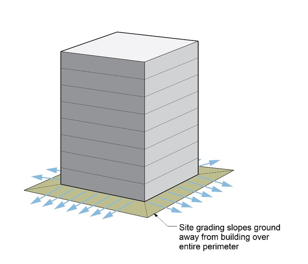
Water management can be challenging on urban sites due to the location of neighboring buildings, roadways and property lines that make it difficult to control surface water runoff and provide site drainage. Figure 1 illustrates the traditional method of providing site drainage that is difficult to achieve on urban sites. Although options for site drainage are limited in urban sites, it is still important to utilize whatever site drainage is possible, such as:
- Sloping sidewalks, driveways, and patios away from the building
- Keeping planters away from foundation perimeters
Source
Groundwater Management for Foundations Above the Groundwater Table
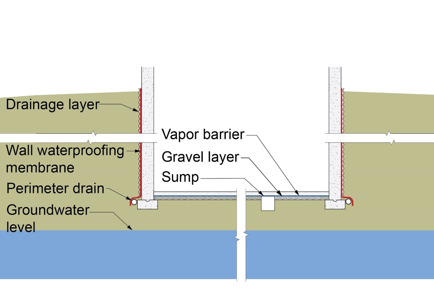
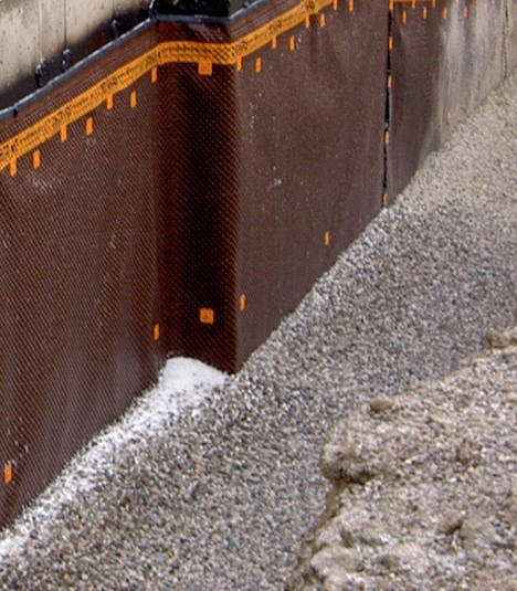
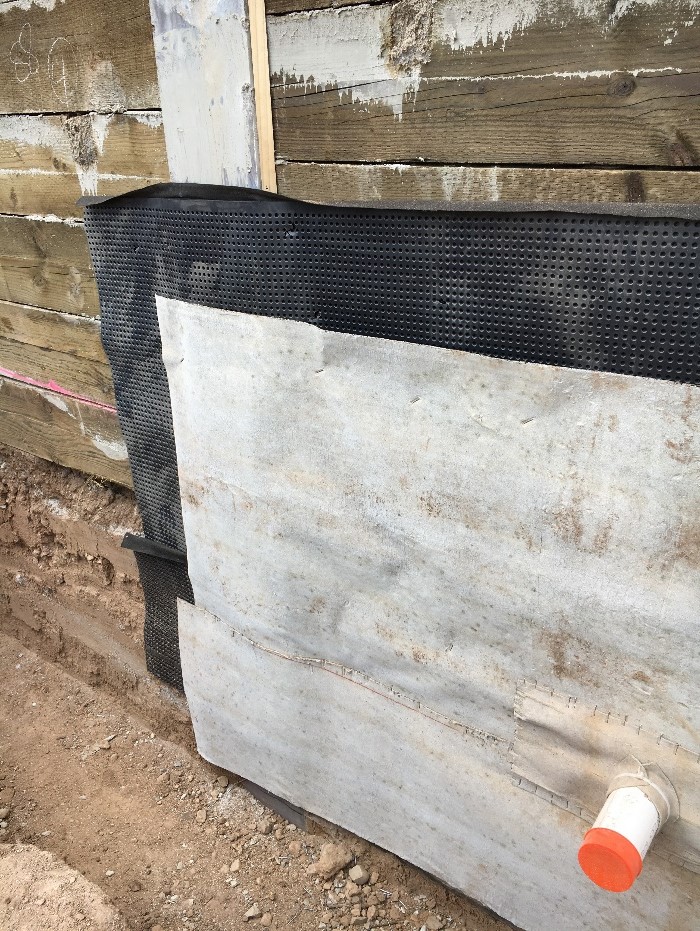
Figures 2a and 2b illustrate the recommended approach for below-grade water management in cases where the foundation assembly is entirely above the groundwater table and access is available around the building perimeter. The waterproofing membrane is located on the exterior of the foundation structure (which is typically concrete). A drainage layer is typically installed on the exterior of the waterproofing membrane and is connected to an exterior perimeter drain (Figure 3). Many drainage layer options are available, such as drainage mats coupled with filter fabric, draining insulation boards, and traditional free-draining backfill such as sand and gravel. The perimeter drain is connected to a sump pit and sump pump, which is typically located internally in urban settings. It is recommended to have backup sump pumps and battery backup to ensure that groundwater can still be managed during power outages.
Source

Source
Source
Groundwater Management for Foundations Below the Groundwater Table
In cases where the foundation is located below the groundwater table, options for groundwater control are typically limited. The most common approaches are described below.
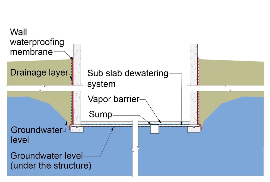
Draw Down
Figure 4 illustrates the “draw down” approach for groundwater control where the foundation assembly is below the groundwater table. Perimeter drainage of the soil adjacent the foundation assembly lowers the “local” ground water table. This approach is dependent on the rate at which groundwater replaces the water removed by the perimeter foundation drainage. This approach is not appropriate where significant groundwater is present and able to move laterally to the soil immediately adjacent the foundation. The “draw down” approach requires experienced civil engineering judgment and design.
In this approach, as in the approach shown in Figure 2, the waterproofing membrane is located on the exterior of the structure, which is typically concrete. A drainage layer is also installed on the exterior of the waterproofing membrane and is connected to an exterior located perimeter drain. The perimeter drain is connected to a sub slab dewatering system, a sump pit and sump pump.
Source
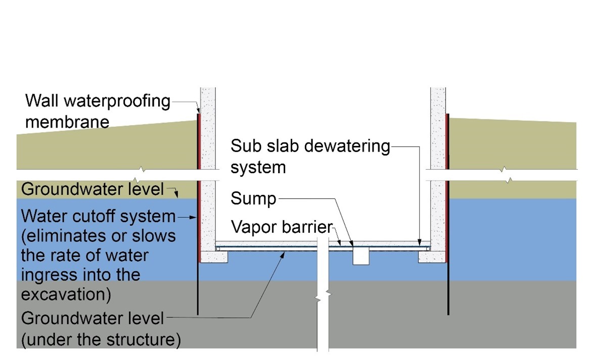
Perimeter Cutoff and Dewatering
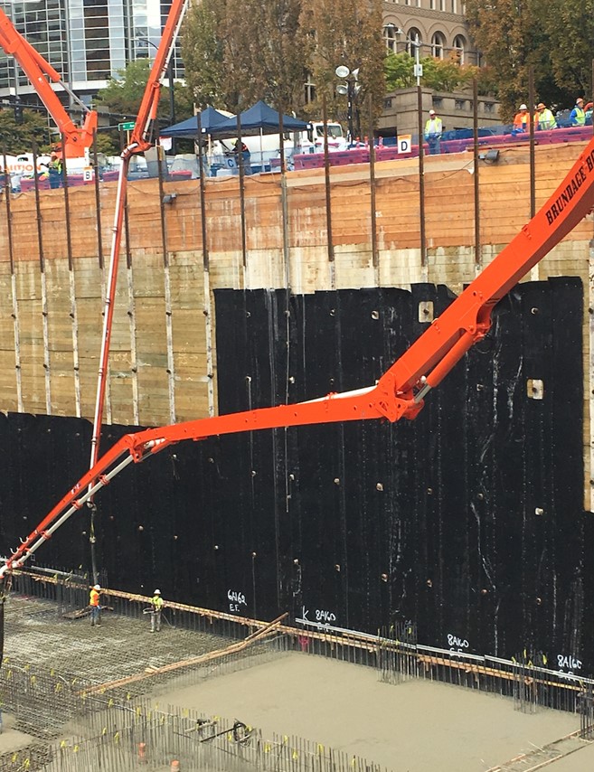
Figure 5 illustrates the “perimeter cutoff and dewatering” approach. In this approach, a water cutoff system eliminates or slows the rate of water ingress into the excavation. The water cutoff systems are typically steel sheet piles extended down into an impermeable layer of soil. The waterproofing membrane is located between the water cutoff system and the concrete foundation walls. A sub-slab drainage system lowers the groundwater level immediately under the structure and redirects it to a sump system. This approach requires experienced civil engineering judgment and design.
Source
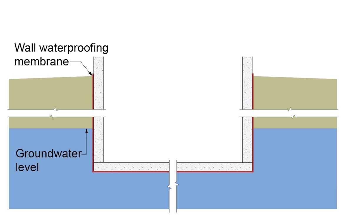
Continuous Waterproofing
Figure 6 illustrates the “continuous waterproofing” approach. In this approach the wall waterproofing system is continuous with the foundation slab waterproofing system. The waterproofing system encases or “wraps” the entire foundation assembly. The groundwater is not lowered and is immediately adjacent all the foundation surfaces. Numerous waterproofing materials are typically used. The most common are described in the Waterproofing Materials section below.
Source
Waterproofing Materials
Note that for all the materials listed below, it is recommended to use a protection layer, such as a board or drainage mat, during backfilling.
Self-Adhered Sheet
Waterproofing self-adhered sheets are typically styrene-butadiene-styrene (SBS) modified asphalt adhered to a polypropylene facer, designed to be applied after the placement of the concrete foundation wall. The seams of the self-adhered sheets should be additionally sealed with a liquid membrane.
Cold Fluid-Applied
Cold fluid-applied waterproofing is typically a polymer modified asphalt emulsion, modified polyurethane or synthetic rubber that can be roller or spray applied after the placement of the concrete foundation wall. Prior to applying the fluid-applied waterproofing, the foundation wall needs to be prepared by filling any voids. During the application process, be sure to monitor the fluid-applied waterproofing for thickness and pinholes. A protection layer (board or drainage mat) should be used during backfilling.
Bentonite
Bentonite waterproofing typically has a geotextile facer or high density polyethylene (HDPE) sheet membrane facer and is mechanically attached to the soil retention system. It is classed as a pre-applied membrane (installed before the placement of the concrete foundation wall) but can also be applied after the foundation wall is placed. The system needs to be protected from rain and water exposure prior to concrete placement.
Pressure-Sensitive Adhesive
Pressure-sensitive adhesive waterproofing is typically a butyl adhesive or a proprietary pressure-sensitive adhesive that is mechanically attached to the soil retention system. It is intended to be installed before the placement of the concrete foundation wall. The system does not need to be protected from rain and water exposure prior to concrete placement.
Critical Details
The following section discusses areas in foundation assemblies that are critical to review in detail when designing groundwater management systems.
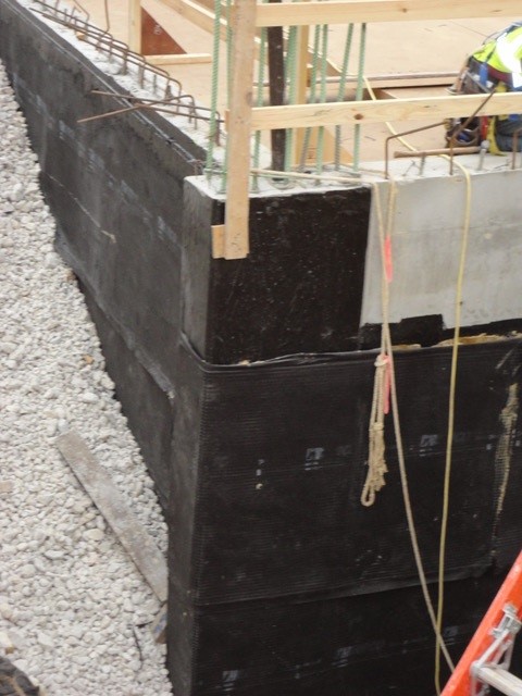
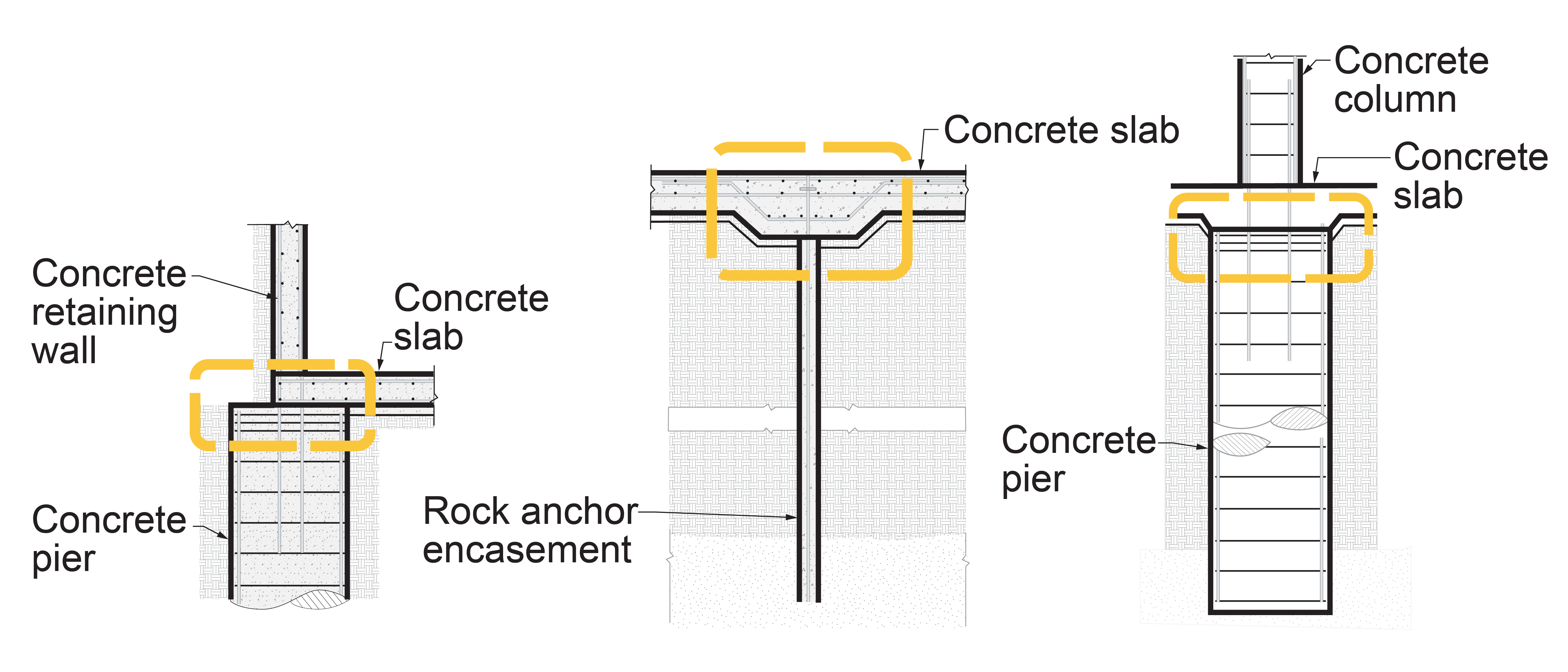
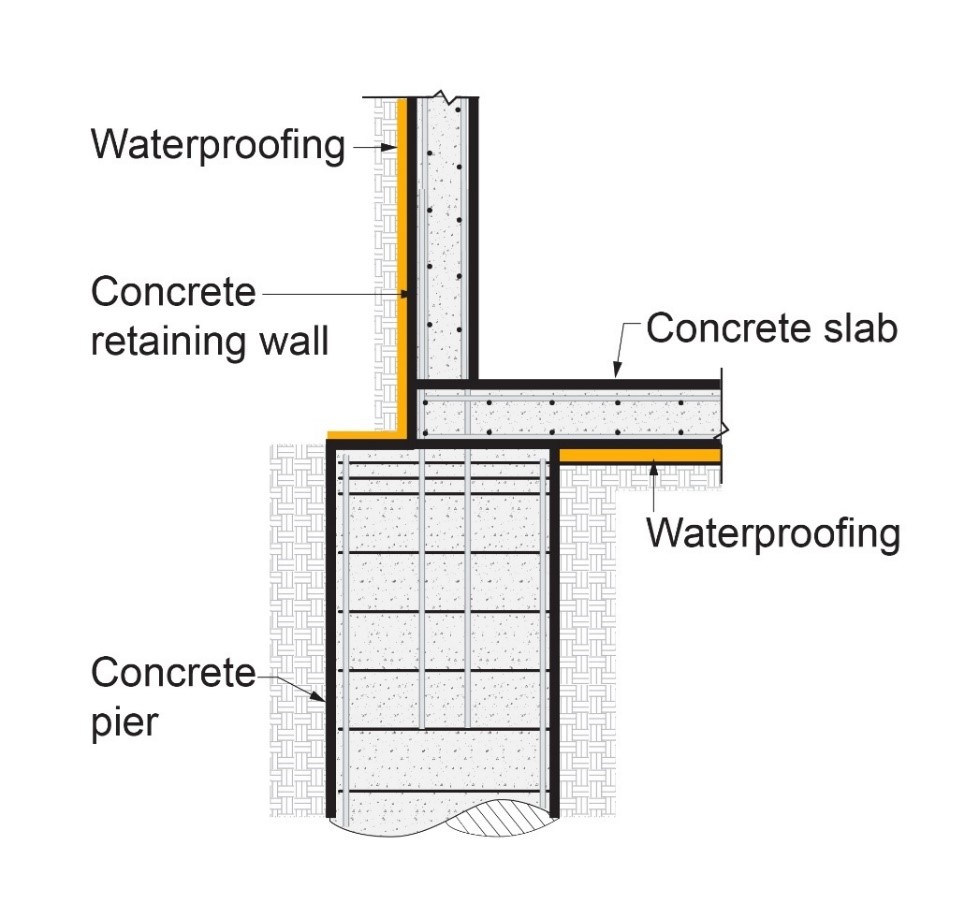
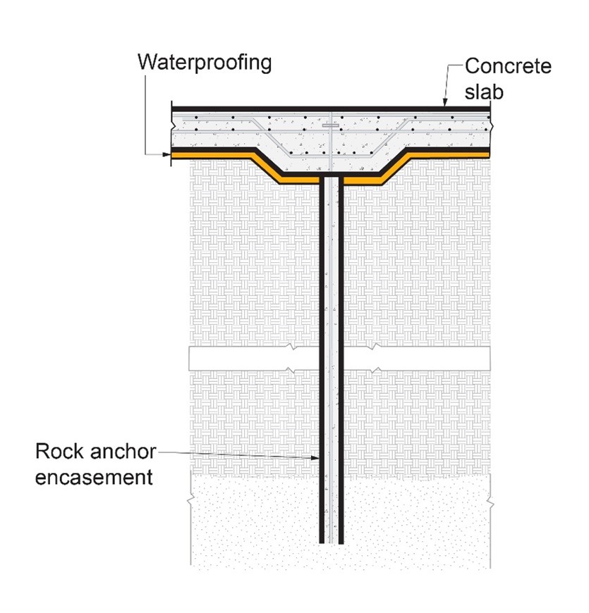
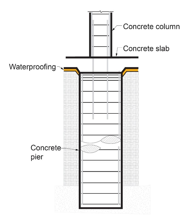
Figure 7 illustrates three foundation details where waterproofing issues often occur in deep foundations: retaining wall/pier connections, rock/anchor connections and column/pier connections.
Source
Figures 8a, 8b, and 8c illustrate some waterproofing and water management strategies to prevent waterproofing issues in the areas shown in Figure 7. Note that in the sections shown in Figure 8a, 8b and 8c, a gap in the waterproofing membrane occurs. This is due to the concrete structural connection necessary at the pier assemblies. The concrete bond between the pier and the slab is relied upon to provide continuity of the waterproofing. These details are often enhanced with injection sealing after concrete placement.
Source
Source
Source
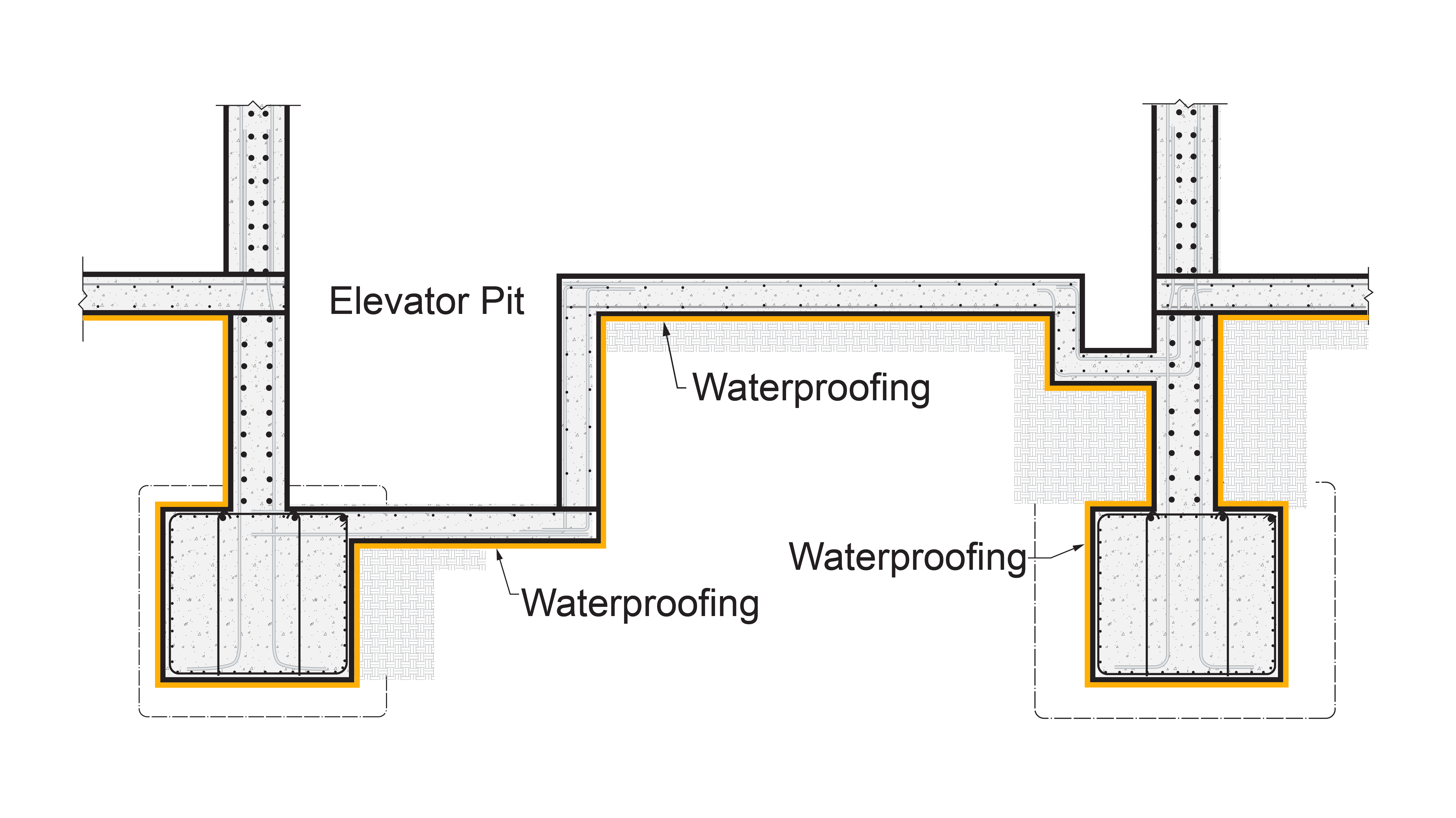
Arguably the most critical detail in below grade water management in multistory multifamily buildings is the elevator pit. Figure 9 illustrates a method to ensure waterproofing continuity across the elevator pit.
Source
Repairs
It is quite common for water leakage into the building foundation to occur during construction. Two standard approaches to address water leakage are:
- Injection sealing
- Interior drainage
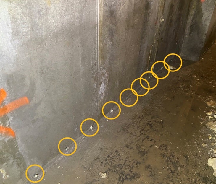
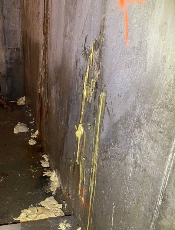
Injection sealing is often used to address intermittent groundwater leakage (Figure 10 and Figure 11).
Source
Source
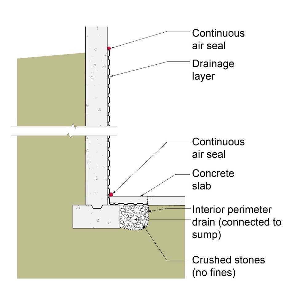
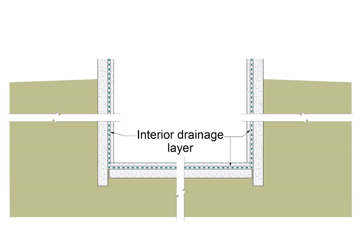
Where significant groundwater leakage is observed, a common approach is interior drainage, which can involve lining the interior perimeter of the foundation assembly with a drainage layer (Figure 12) or lining the entire interior of the foundation assembly, including the slab, with a drainage layer (Figure 13).
Source
Source
Ensuring Success
Provide continuous waterproofing along below grade areas of the foundation wall, giving extra consideration to areas that are prone to waterproofing issues. Seal all penetrations through the waterproofing membrane. Inspect the foundation for any water leaks post-construction. Address any intermittent leaks with injection sealing. Address any significant leaks by adding a drainage layer around the interior perimeter of the foundation or by lining the entire foundation assembly, including the slab, with a drainage layer.
Region
No climate-specific information applies.
Training
Right and Wrong Images
Source
Source
Compliance
More Info
References and Resources
*For non-dated media, such as websites, the date listed is the date accessed.
Contributors to this Guide
The following authors and organizations contributed to the content in this Guide.
Building Science Corporation, lead for the Building Science Consortium (BSC), a DOE Building America Research Team.
Pacific Northwest National Laboratory
Questions? Comments? Contact our webmaster.