Showing results 1 - 117 of 117
Image
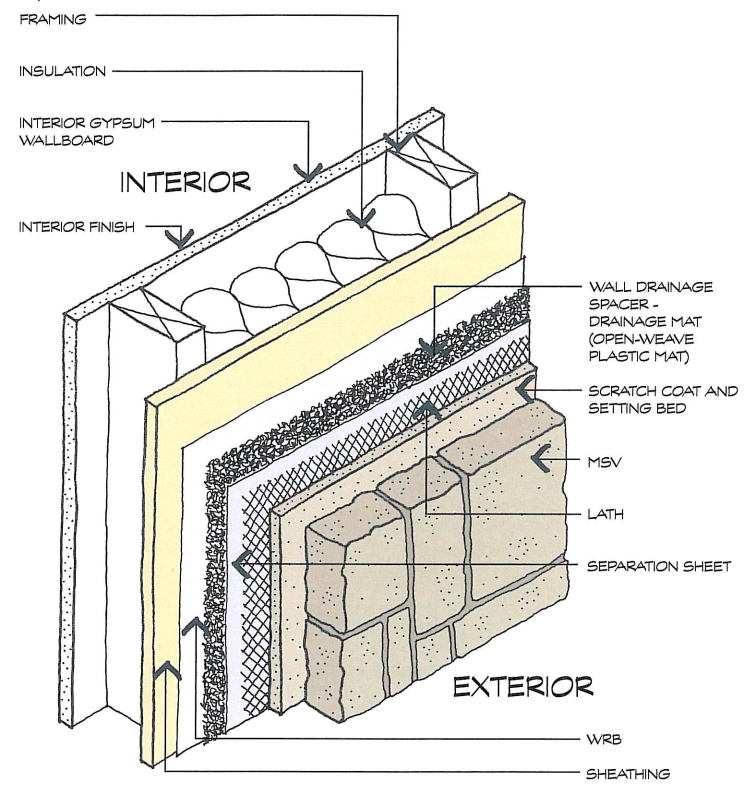
A plastic fiber drainage mat rainscreen provides uniform support for the siding and allows moisture to flow horizontally and diagonally in addition to vertically.
Image
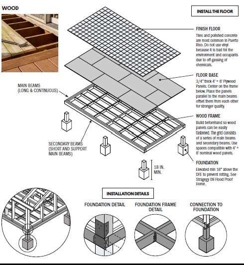
A raised wood pier foundation can raise the subfloor above the design flood elevation.
Image
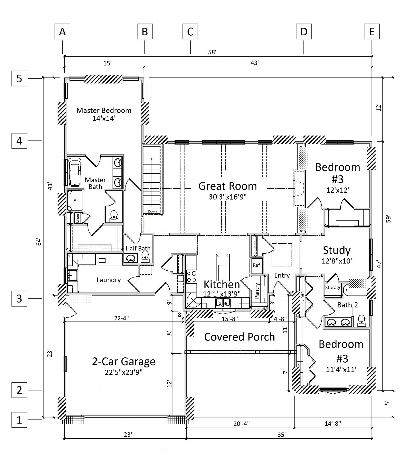
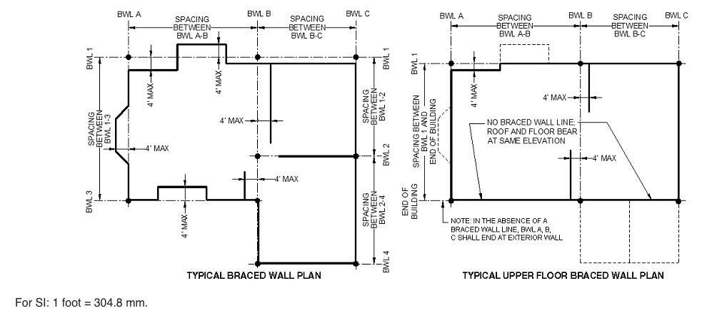
A single-story house floor plan showing braced wall line locations at A through E and 1 through 5
Image
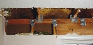
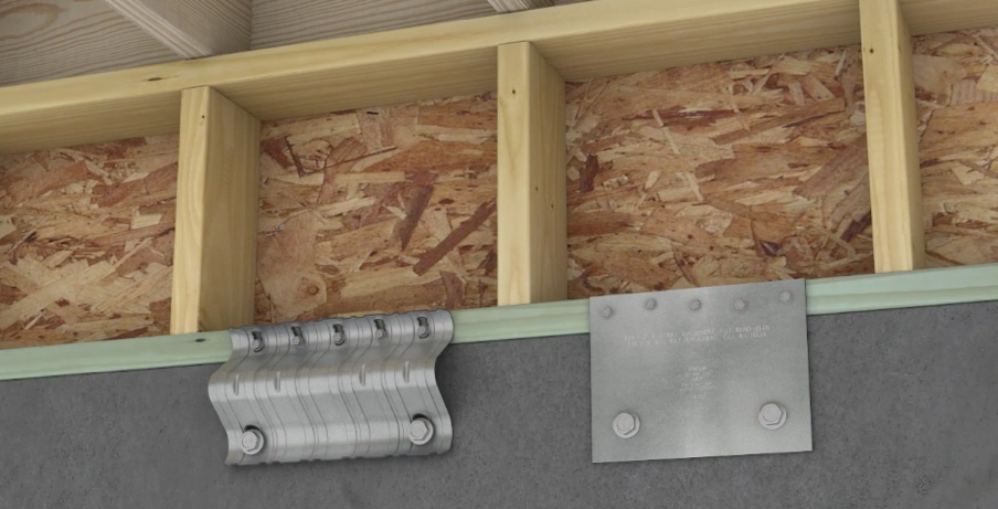
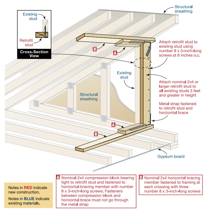
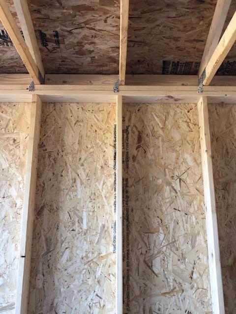
Add metal connectors to strengthen framing connections in an existing wall from inside the home by removing drywall.
Image

Image
Image
Image
Image
Building America worked with Mercedes Homes in east Florida to design homes using cast-in-place concrete walls capable of withstanding wind-blown debris impacts of up to 200 mph (Source: Mercedes Homes).
Image
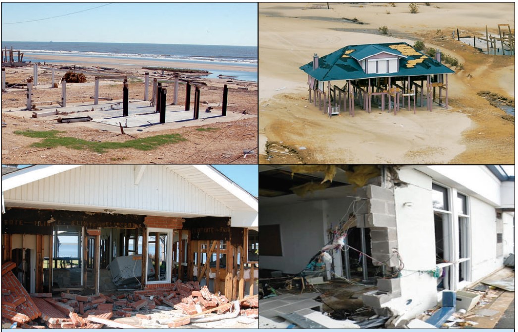
Buildings damaged by a hurricane storm surge: upper homes on gulf shoreline were hit by large waves above the lowest floor, lower left home on bay and right school 1.3 miles from gulf shoreline were hit by surge and small waves.
Image
Image
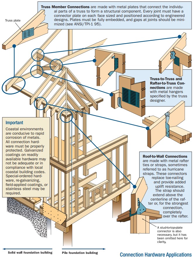
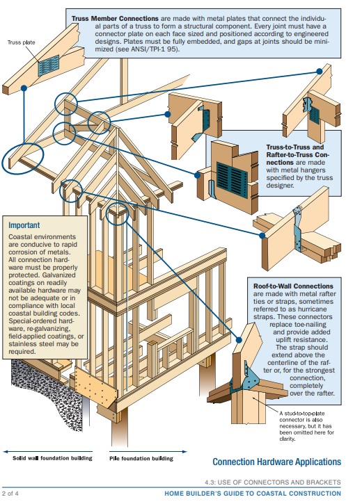
Connecting hardware helps tie the roof to the walls to ensure a continuous load path to improve a building’s resistance to high winds, floods, and earthquakes.
Image
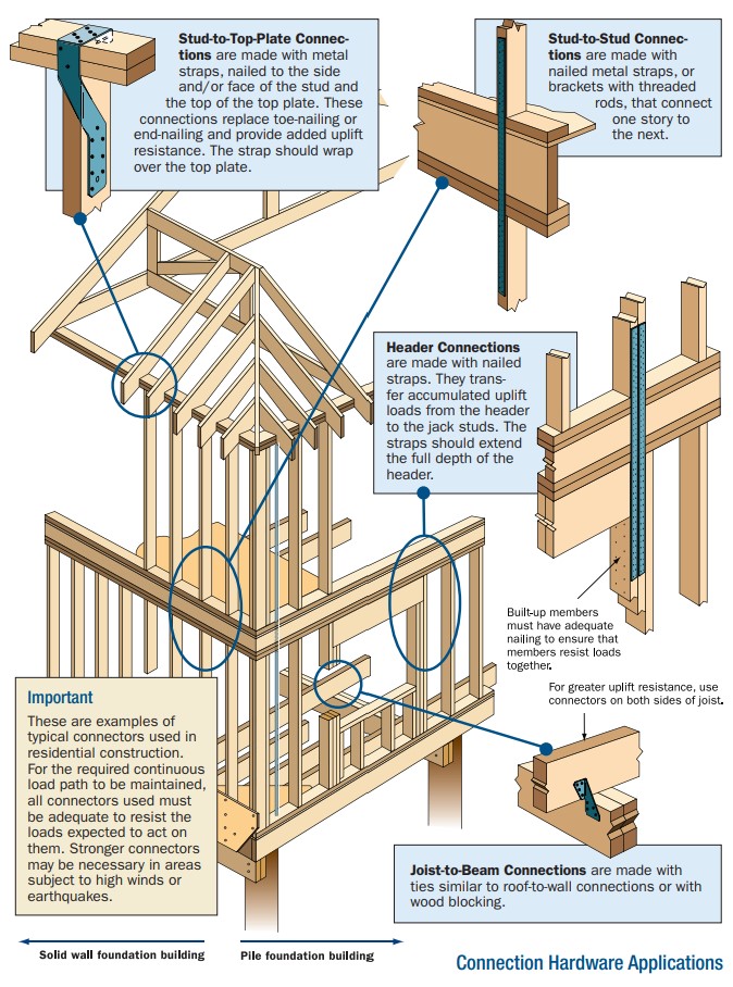
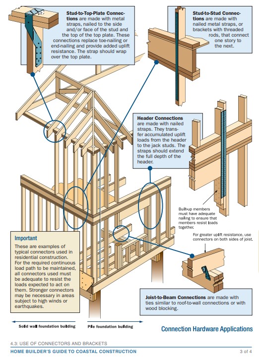
Connecting hardware helps tie the walls to the top plates and rim joists to ensure a continuous load path to improve a building’s resistance to high winds, floods, and earthquakes.
Image
Image
Correct seismic retrofit hardware for securing the sill plate to foundation wall
Image
Image
Image

Durability concerns on a house continuously sheathed with a proprietary fiber structural panel used as bracing. Photo 1 of 2.
Image
Durability concerns on a house continuously sheathed with a proprietary fiber structural panel used as bracing. Photo 2 of 2.
Image
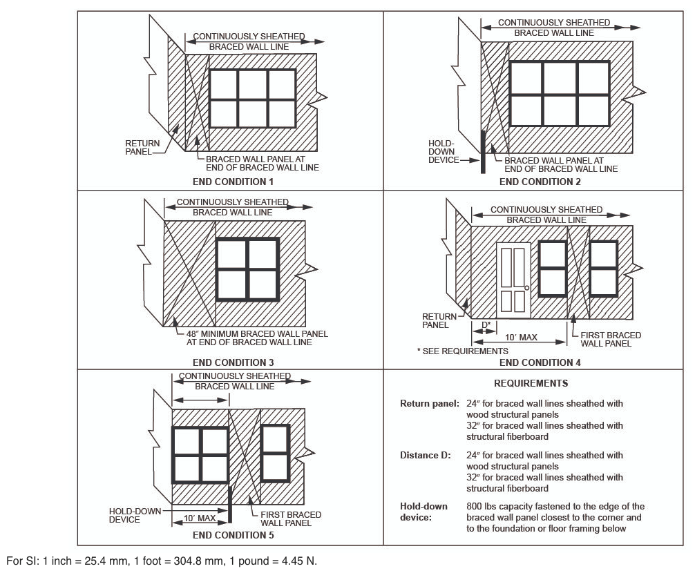
End conditions for braced wall lines with continuous sheathing, Figure R602.10.7 in the IRC
Image
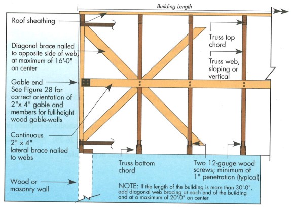
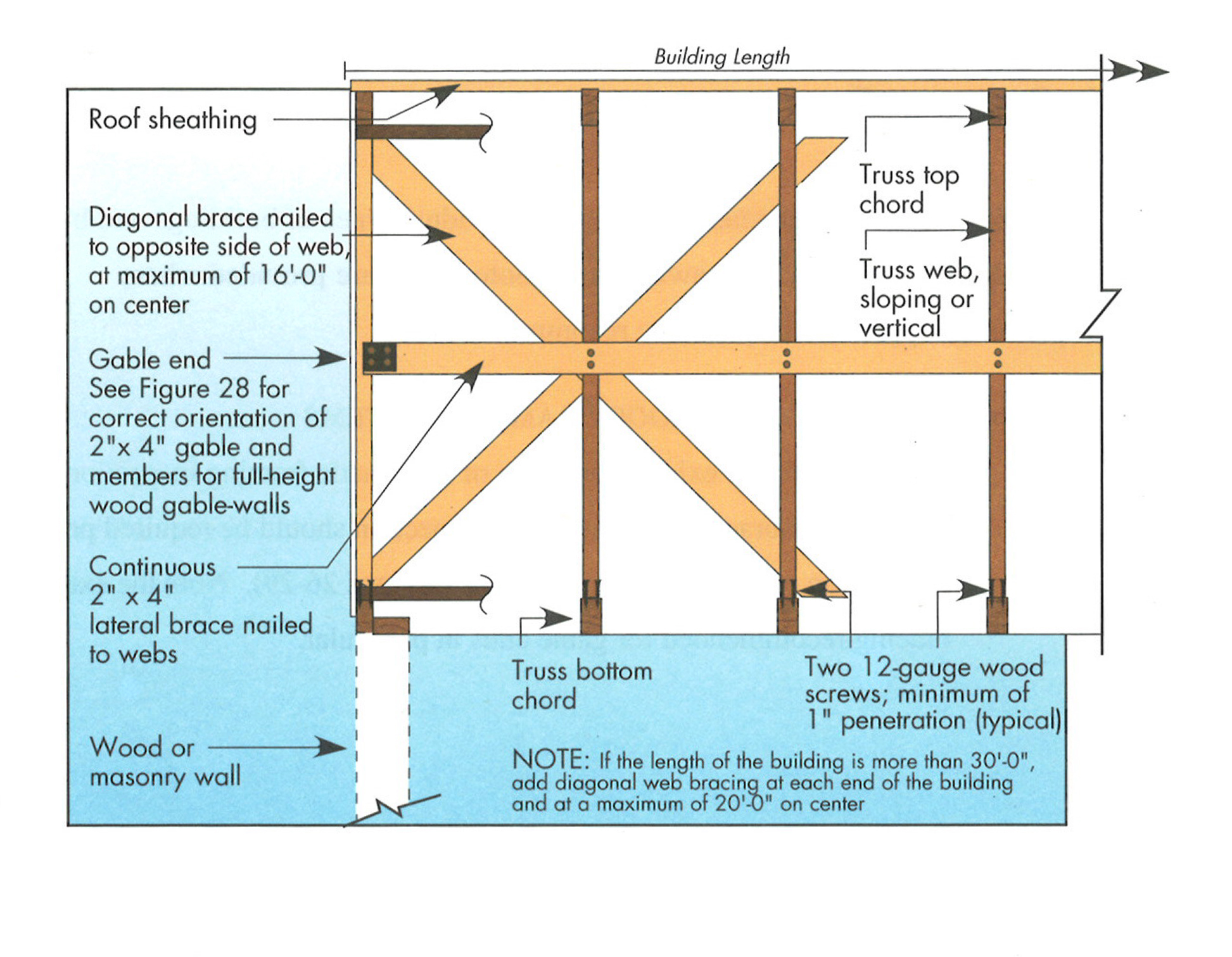
Example A of a gable truss and gable end wall bracing for a home in a hurricane region
Image

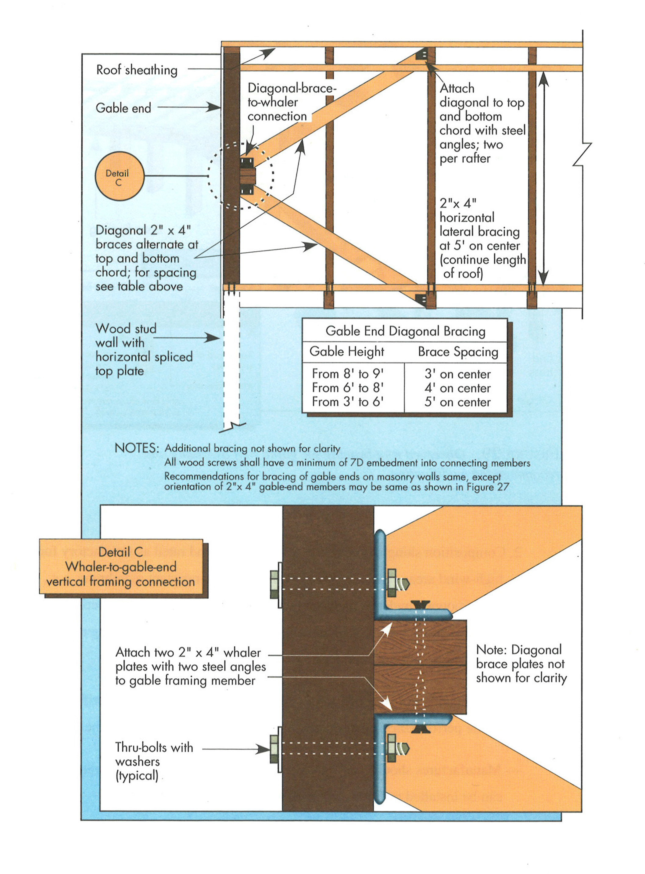
Example B of a gable truss and gable end wall bracing for a home in a hurricane region
Image
Example of masonry construction. Wall separated from building envelope due to inadequate vertical wall reinforcing in connection to horizontal tie-beam.
Image
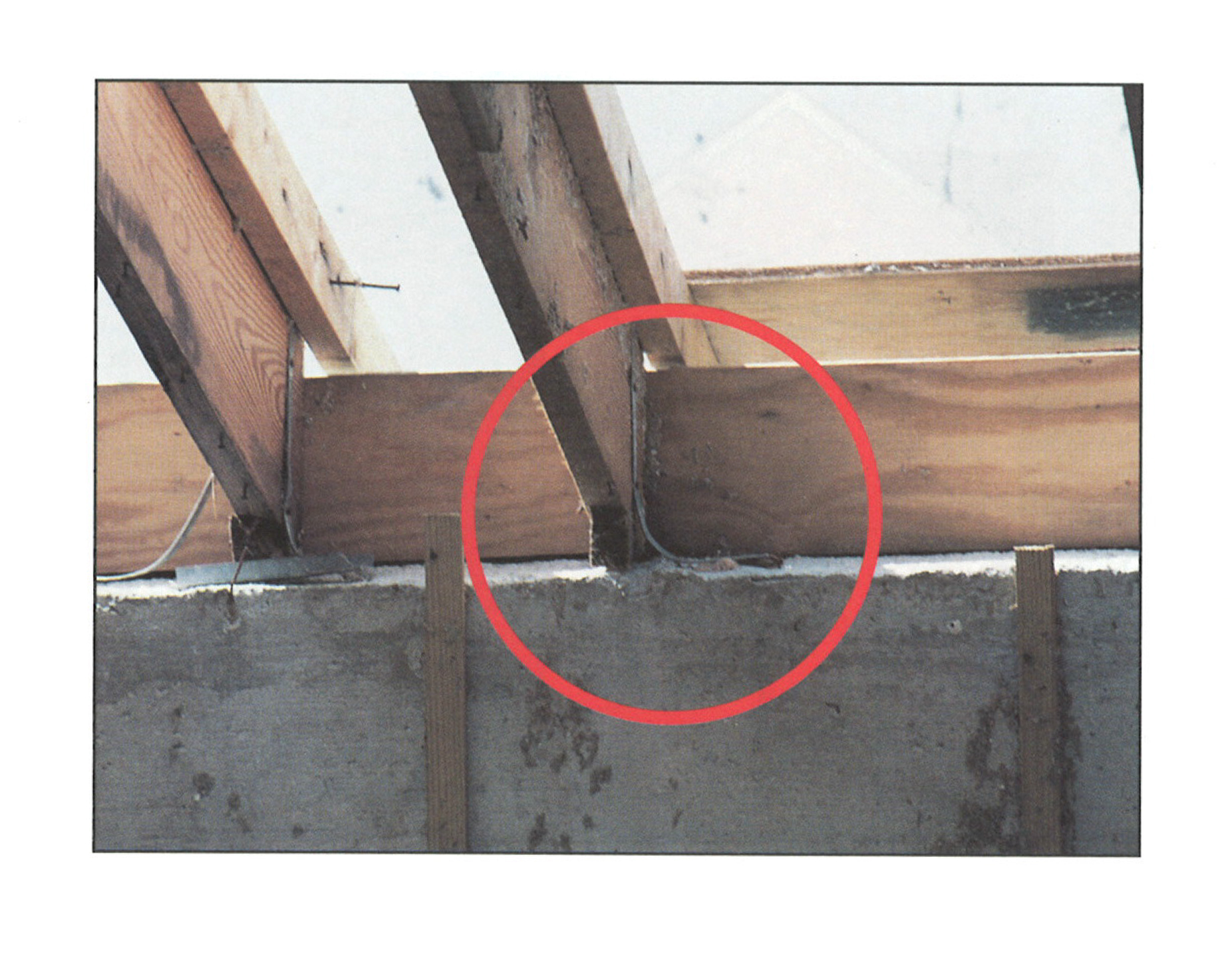
Failure of a freestanding concrete masonry end wall due to discontinuous tie-beam when exposed to hurricane force winds.
Image
Image
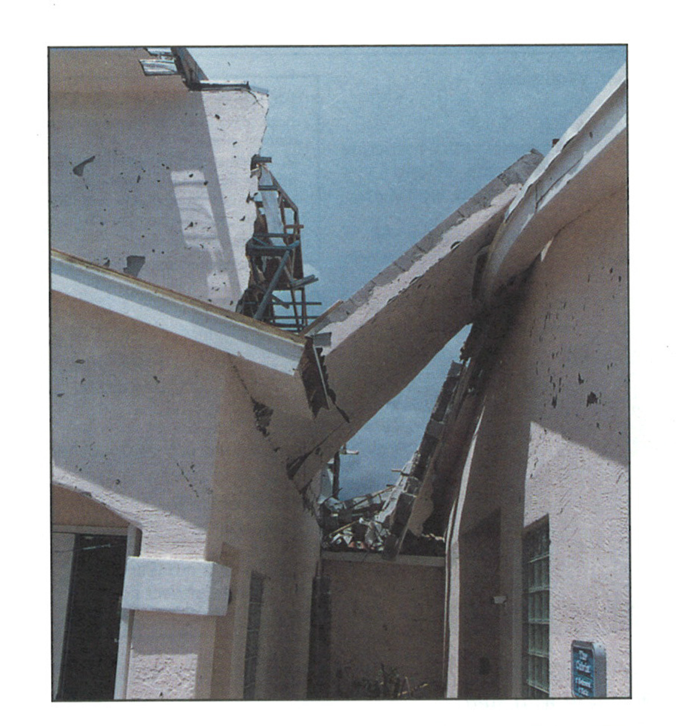
Firewall separation. Results from building corners being discontinuous with tie-beams.
Image
Image
Image
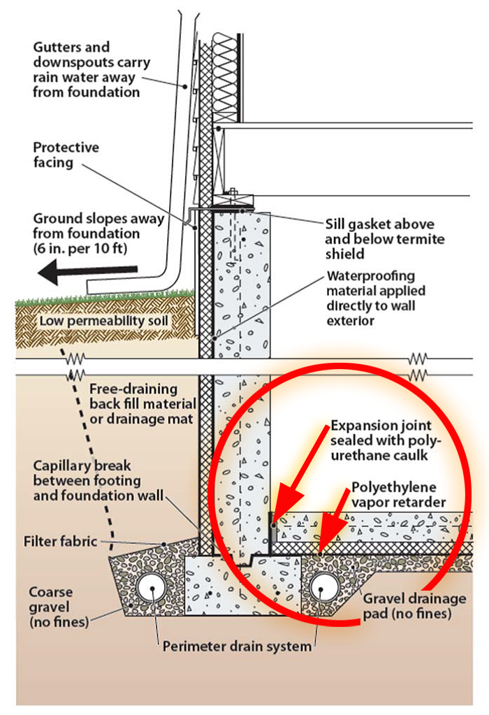
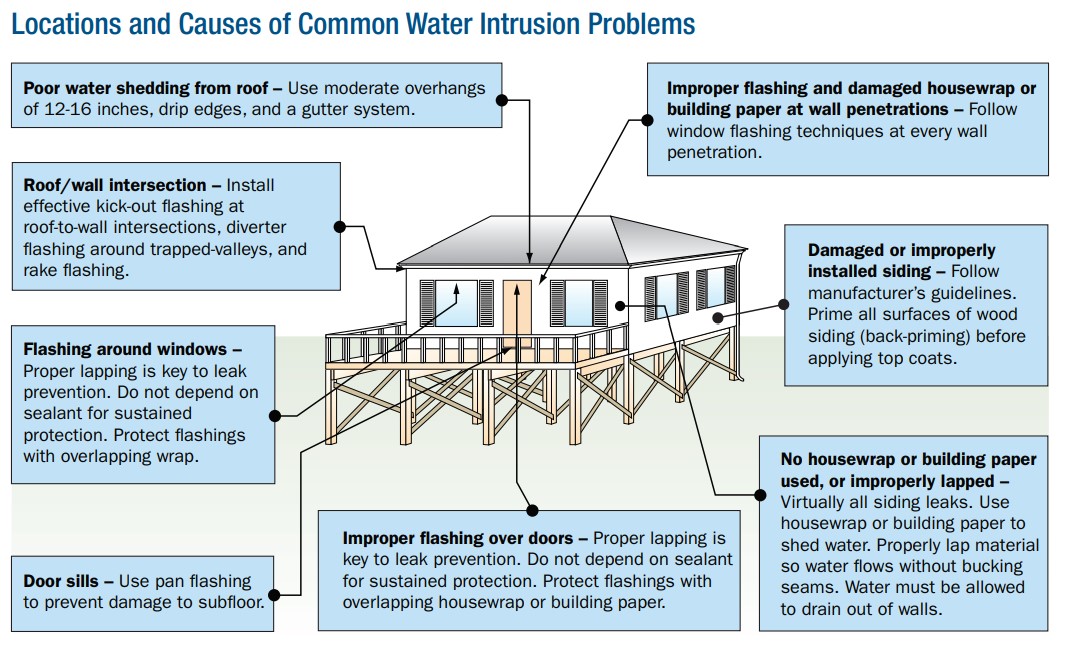
Good water management practices like sloping grade away from house, and installing gutters, perimeter drain pipe, a capillary break, and free-draining soils or drainage mat protect the foundation from water saturation.
Image

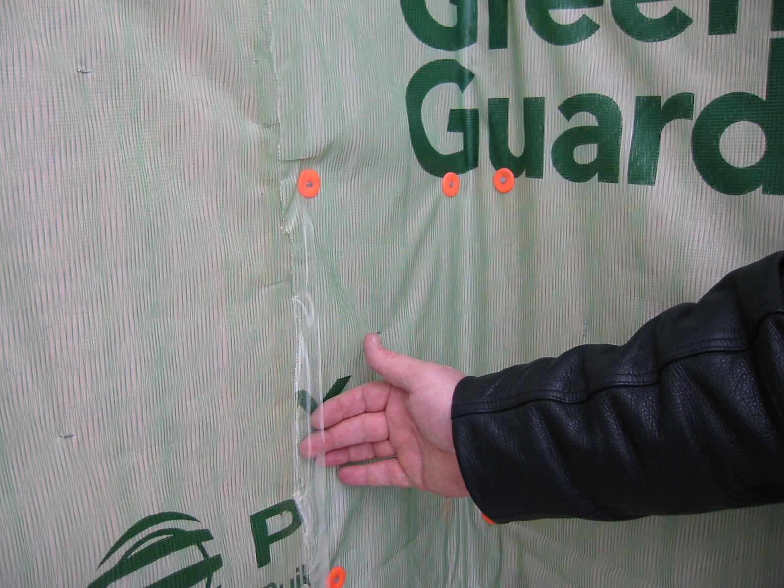
House wrap is sealed at all seams and overlaps flashing to serve as a continuous drainage plane over the exterior walls.
Image
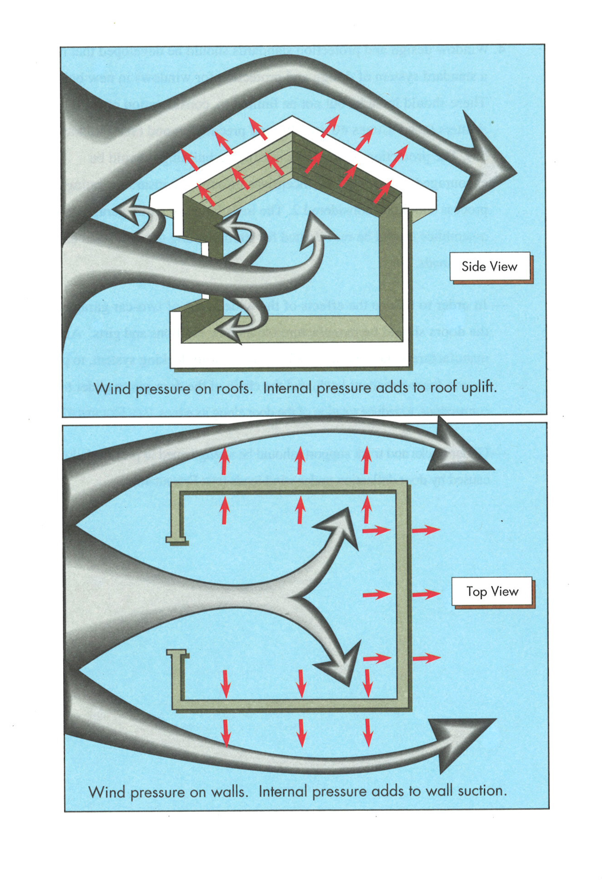
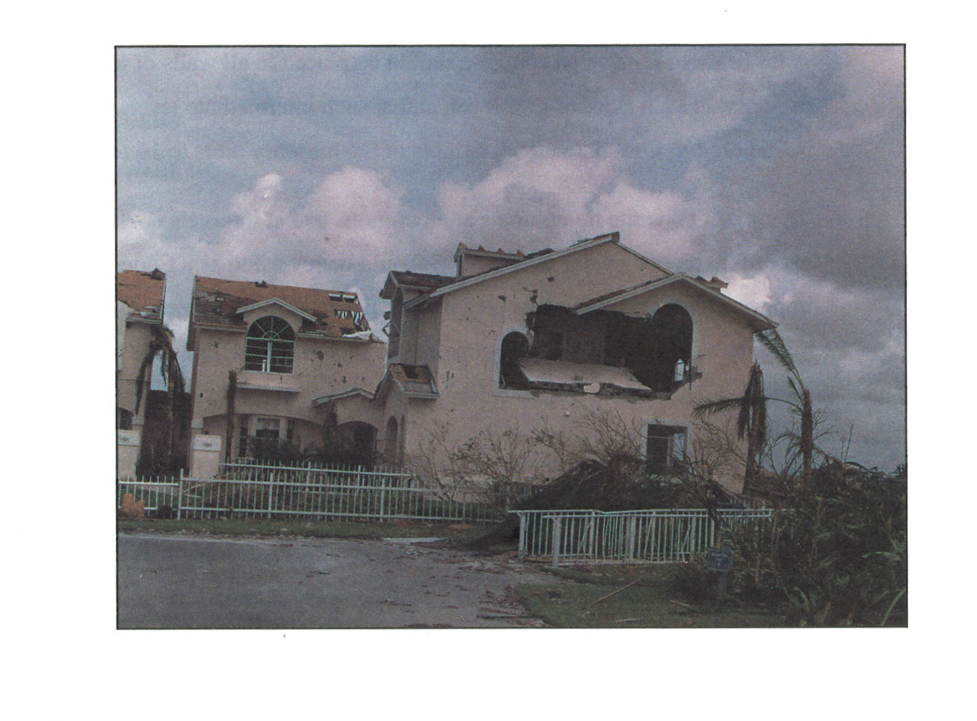
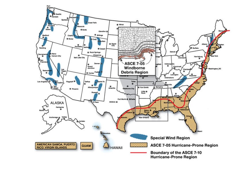
Hurricane force winds that breach external windows and doors can then cause failure of the entire building due to internal pressures on walls and roof.
Image
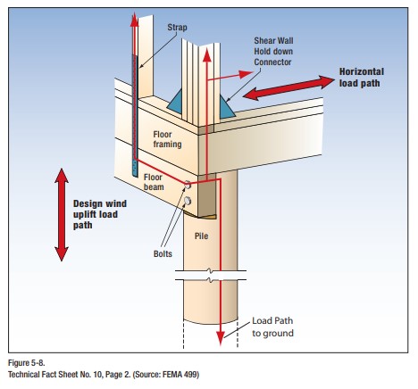
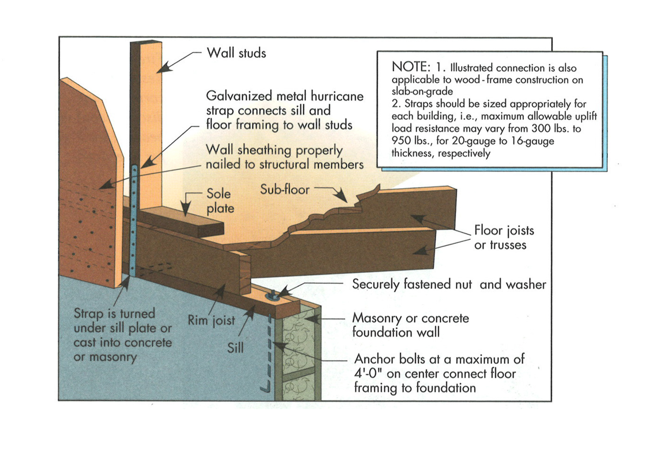
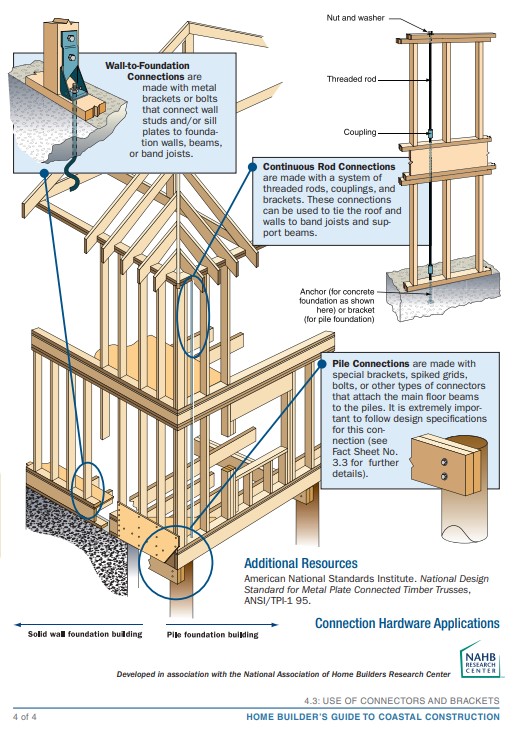
Hurricane straps, hold-down connectors, and bolts help to transfer loads from the building’s walls to its foundation, increasing resistance to vertical and horizontal pressures acting on the building from wind, waves, or ground movement.
Image
Image
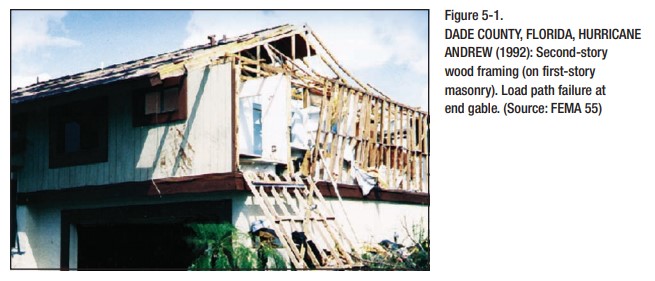
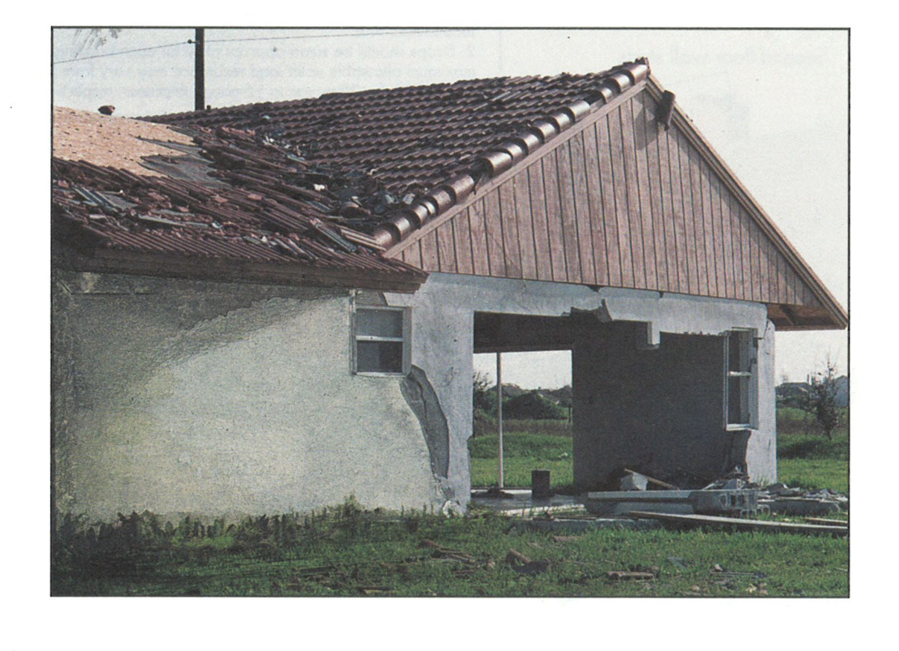
Improper continuous load path design lacking bracing results in the failure of gable end walls under high wind conditions.
Image
Image
In areas prone to high winds and hurricanes, double vertical “jack trim” and horizontal “header” and “sill” studs are recommended on all sides of window and door openings.
Image
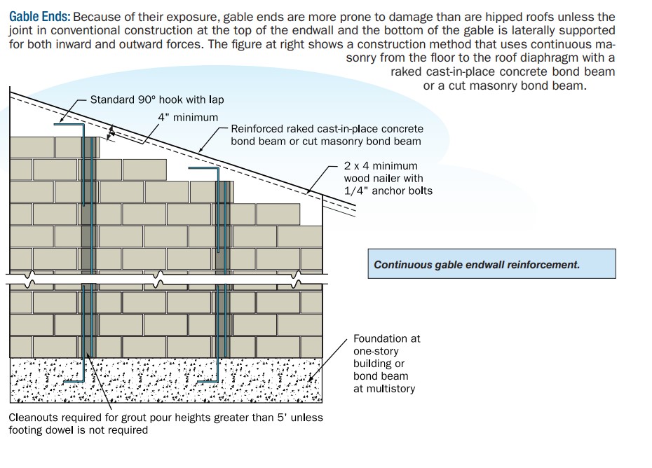
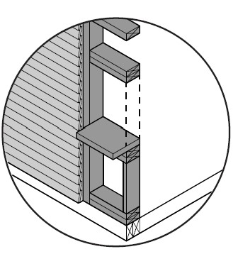
In high wind areas, provide lateral support to masonry end walls to resist high winds.
Image
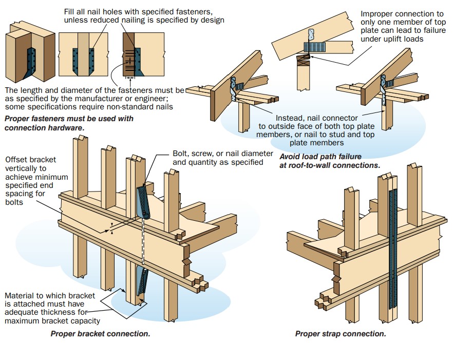
In high-wind regions, special hardware is used for most framing connections; toe-nailing is not acceptable.
Image
Image
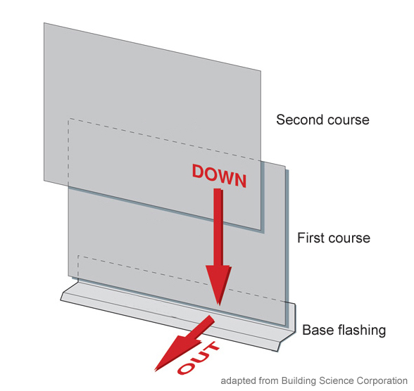
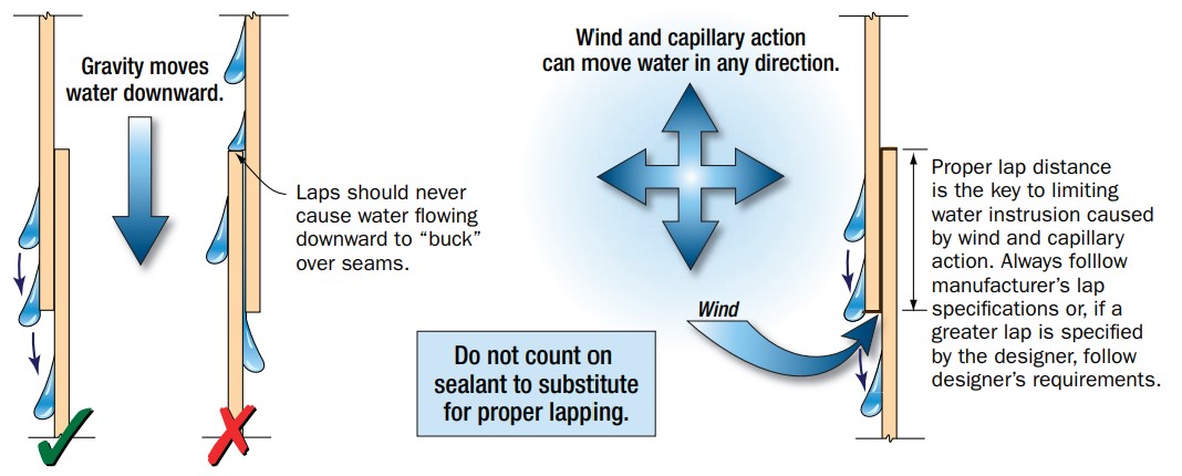
Install all layers of the drainage plane to overlap, not underlap, to direct bulk water down and out of the wall.
Image
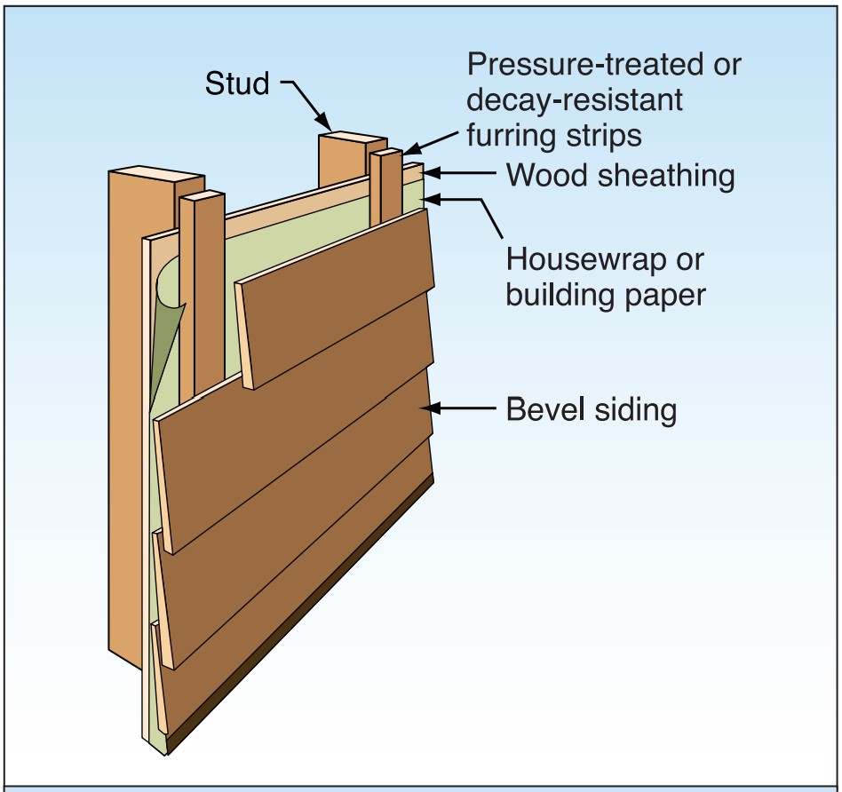
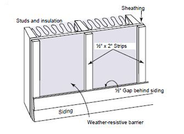
Install furring strips over house wrap to provide a rainscreen behind wood siding.
Image
Image

Image

Image
Image
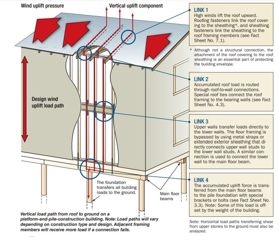
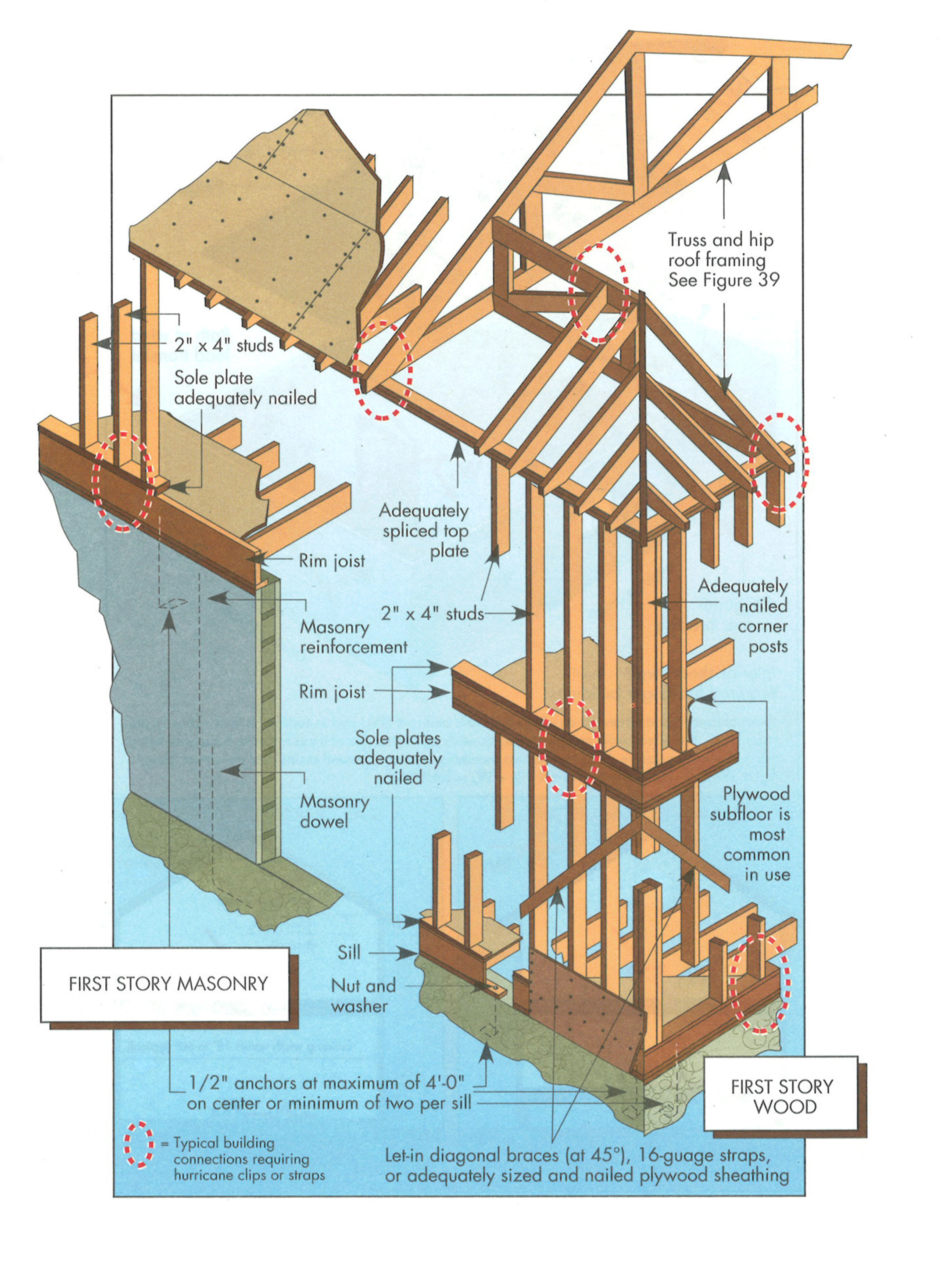
Key connection points for a continuous load path for earthquake and high wind disaster resistance
Image
Image
Lower-story wall anchorage to masonry (or concrete) base. Straps properly nailed at wall studs.
Image
Image
Image
Moisture-resistant plastic and fiber cement exterior trim and cladding are indistinguishable from wood building elements.
Image
Image
Image
Image
Image
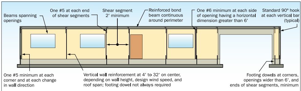
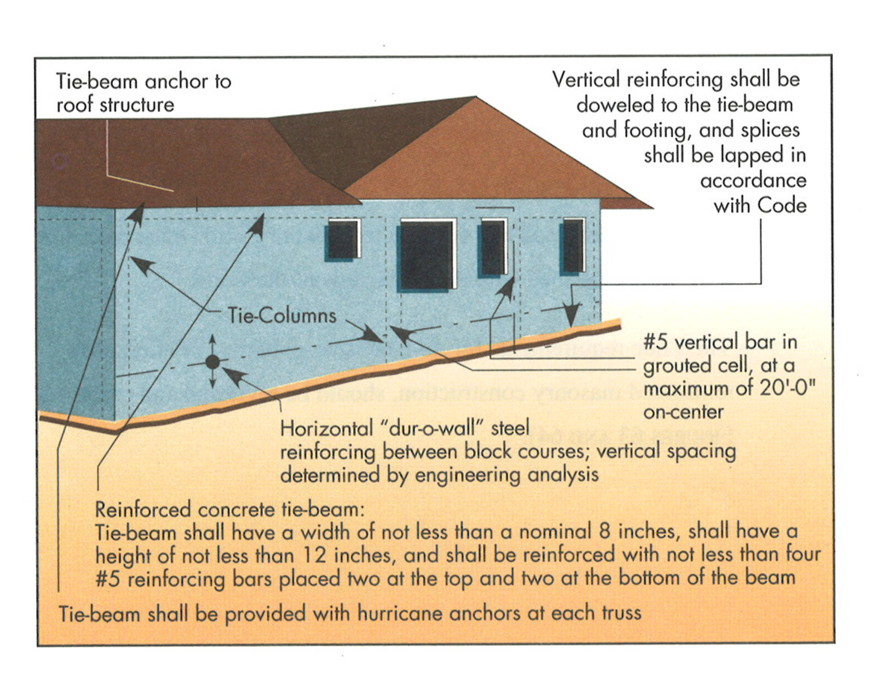
Properly reinforce masonry walls in coastal locations to resist high winds and waves.
Image

Image
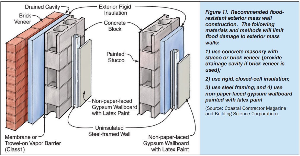
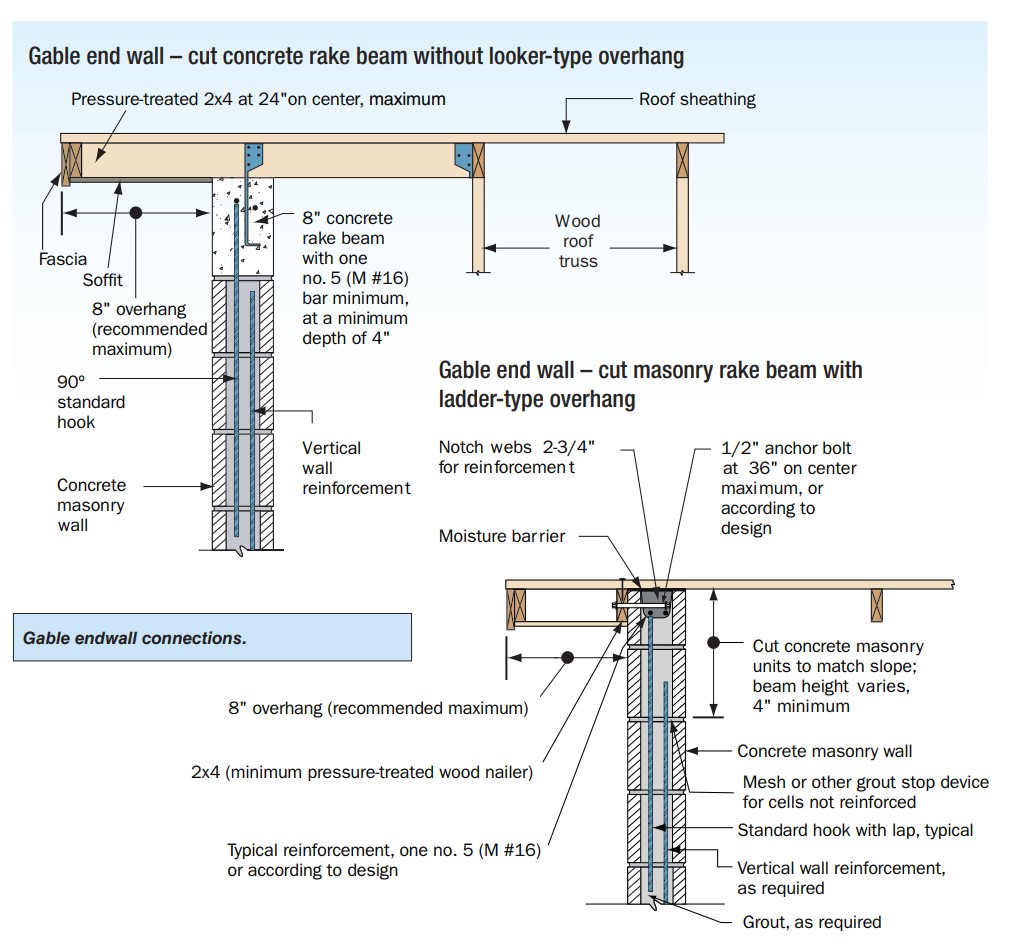
Recommended flood resistant wall construction for concrete block walls with stucco or brick veneer.
Image

Image
Image
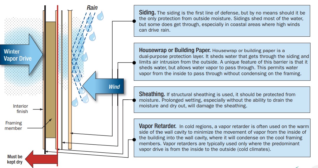
Redundant moisture barriers including siding, house wrap, and coated sheathing can help protect walls from excess moisture, while vapor retarders prevent vapor from entering the wall from the house, for example from a bathroom or kitchen.
Image
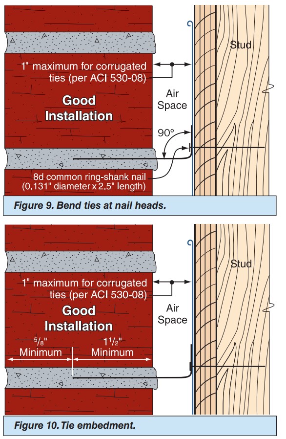
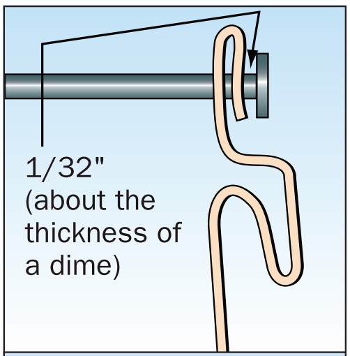
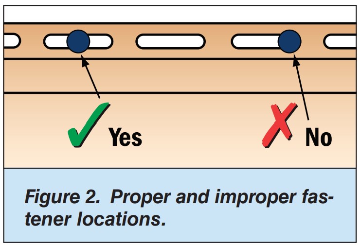
Right – The ties are bent at a 90 degree angle at the nail head and embedded into the mortar joint at least 1.5 inches.
Image

Right - A continuous load path connects the roof and wall framing to the foundation.
Image
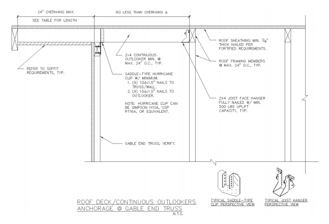
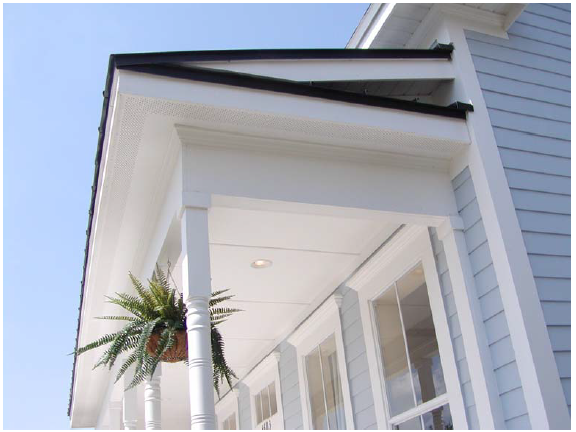
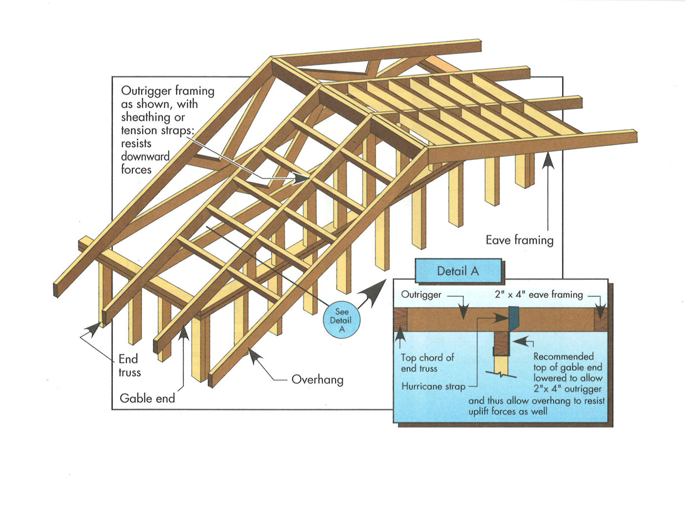
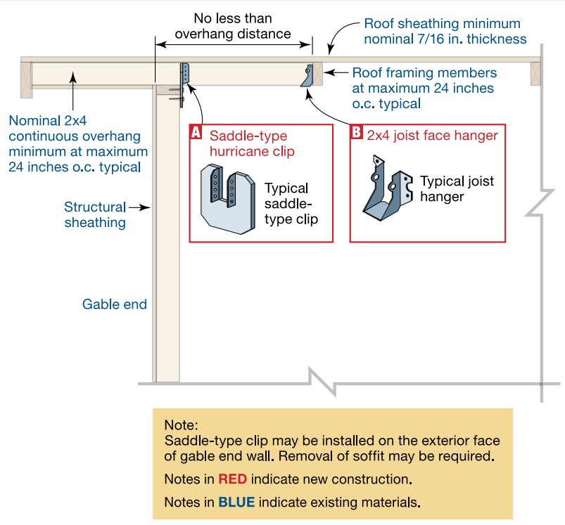
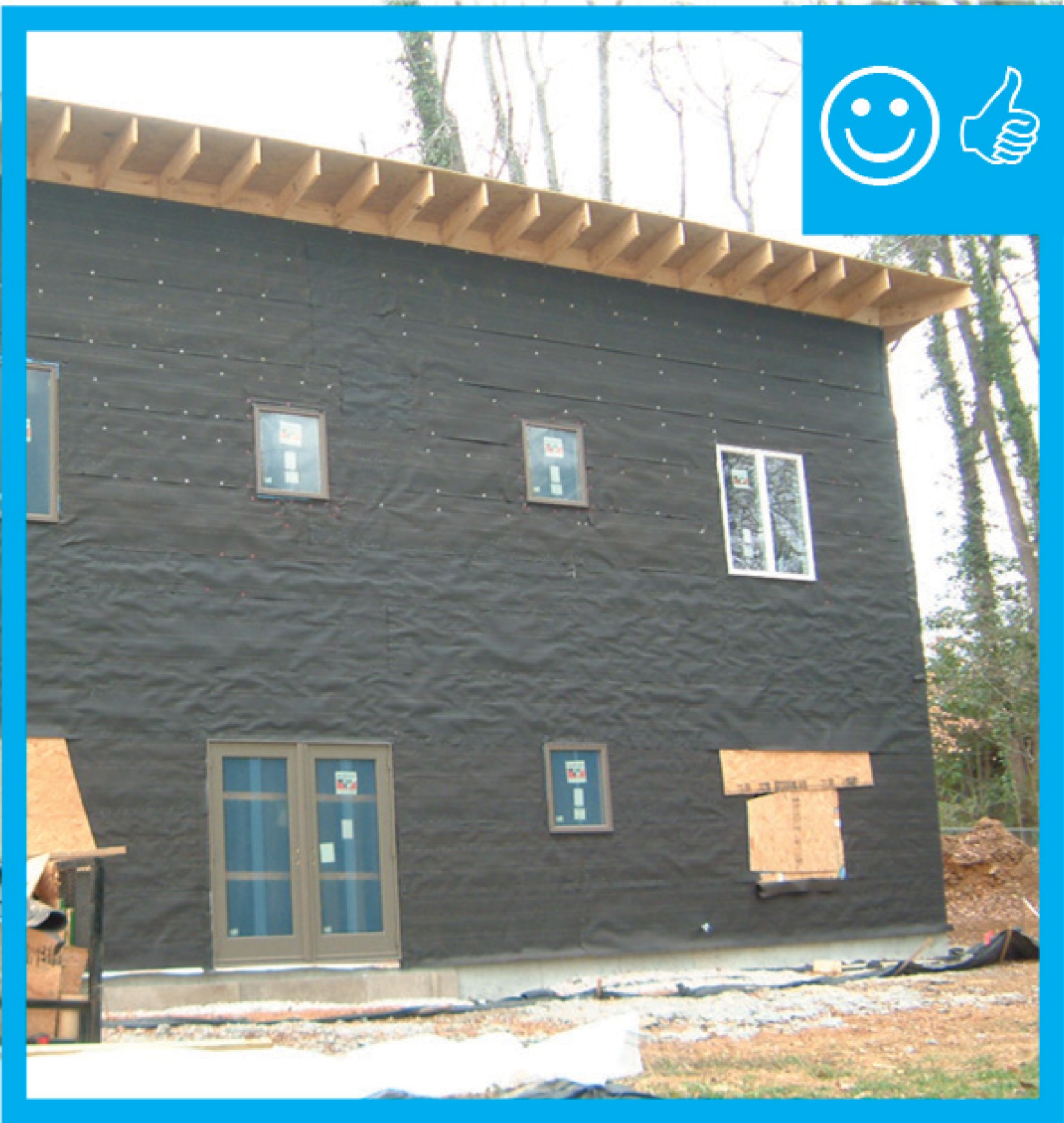
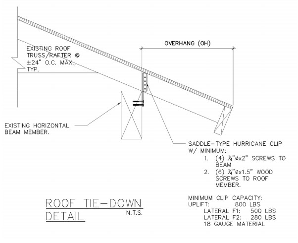
Right - Anchorage to increase the wind uplift resistance of outlookers forming the overhang at a gable end truss wall.
Image

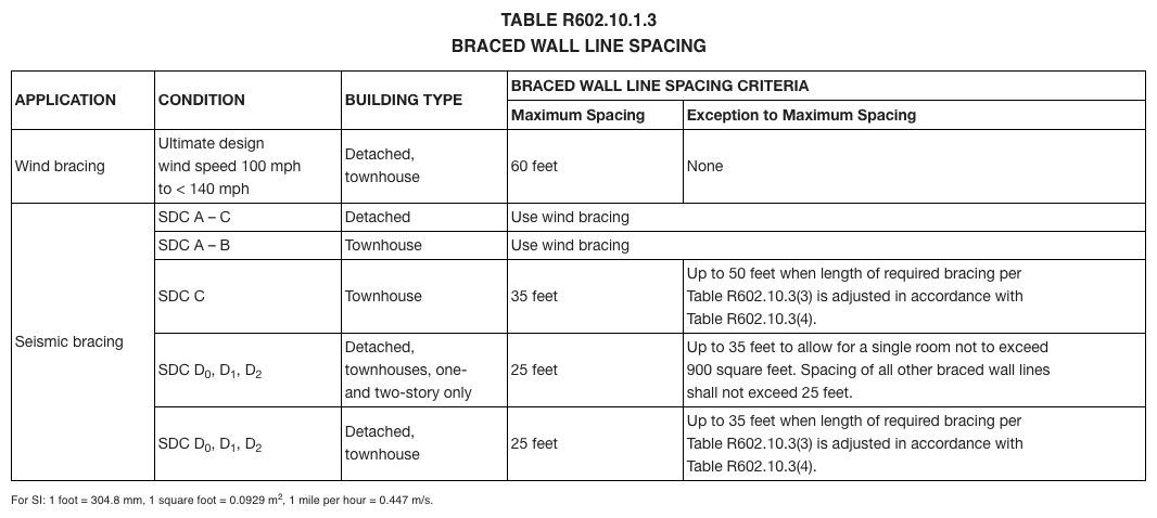
Right - Braced wall line spacing is correctly calculated for determining wall bracing in accordance with the IRC.
Image

Right - Engineered portal frames are used for wall bracing to resist wind and earthquake loads.
Image
Image
Image
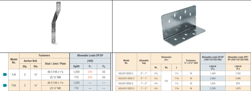
Right – Examples of wall stud to sill plate and foundation and wall rod connectors and brackets.
Image
Right – Examples of wall stud to top plate and stud to rim joist framing connectors and brackets.
Image
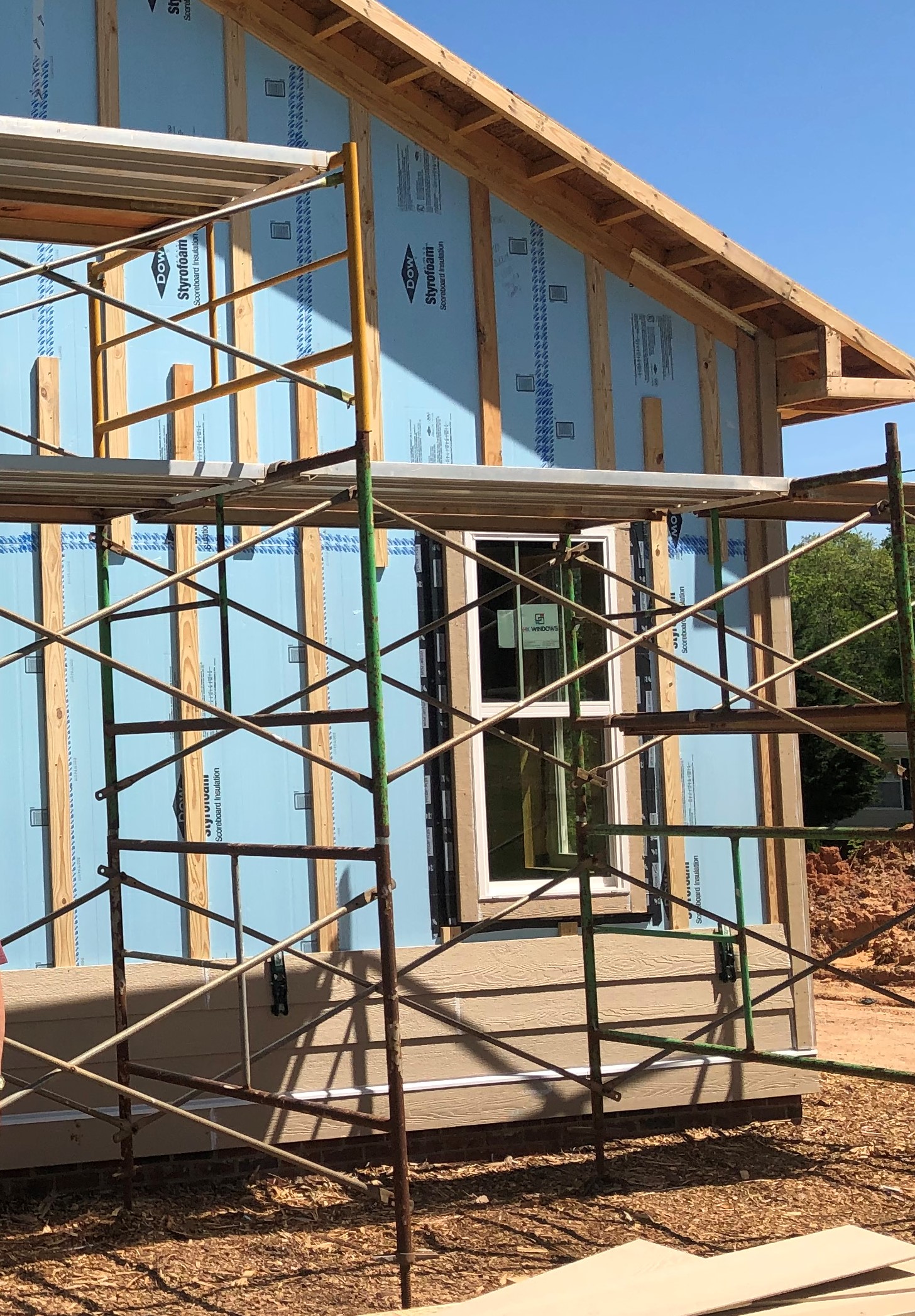
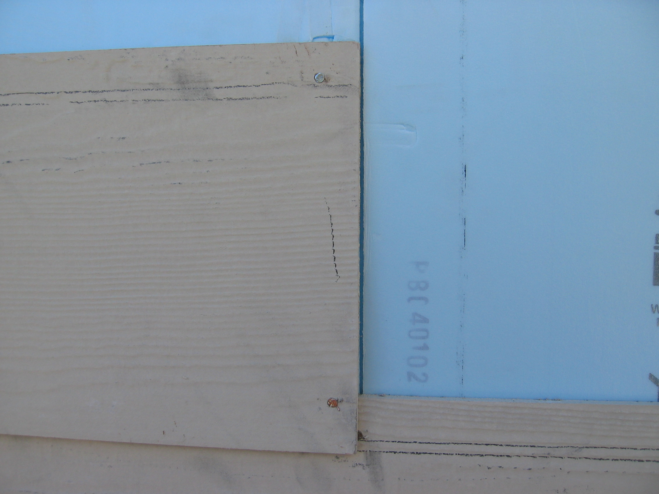
Right – Furring strips provide a drainage gap between the rigid foam and the siding.
Image
Image
Image
Image
Right – The building felt is installed on all exterior walls and provides a complete drainage system
Image
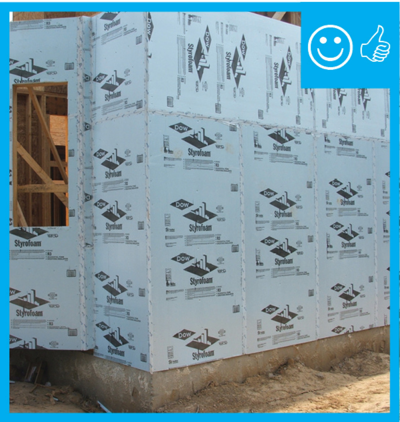
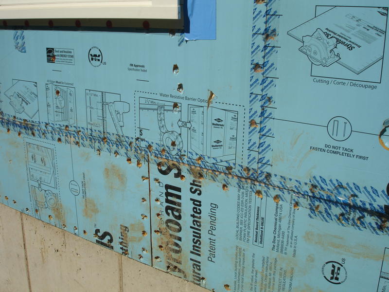
Right – The rigid insulation covers all exterior walls and all seams are taped to provide a complete drainage system
Image
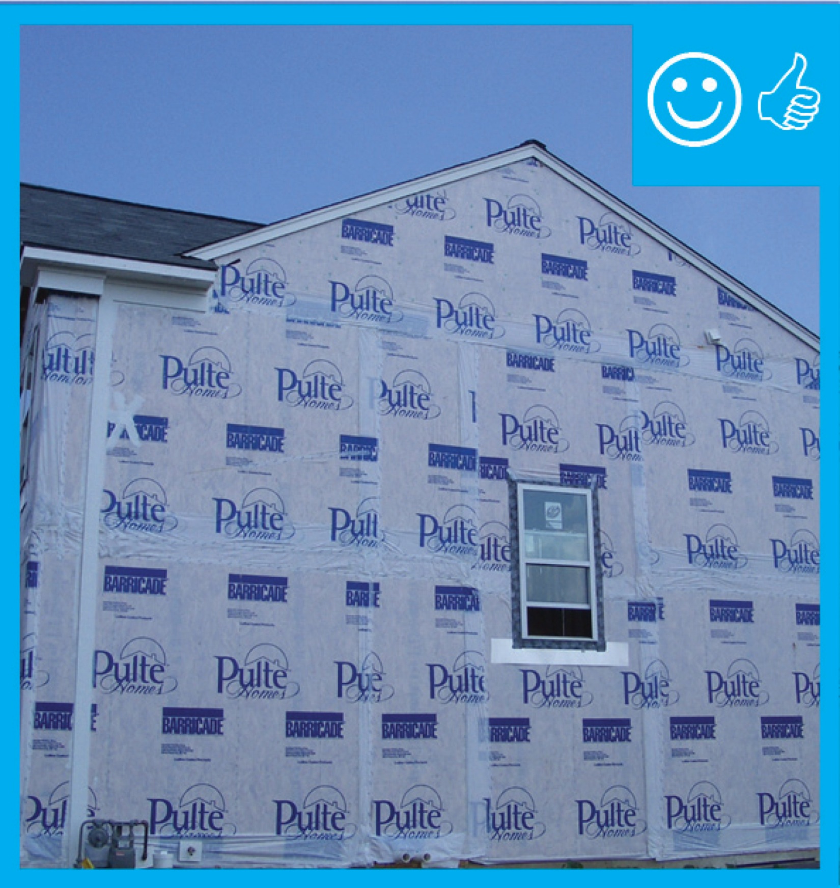
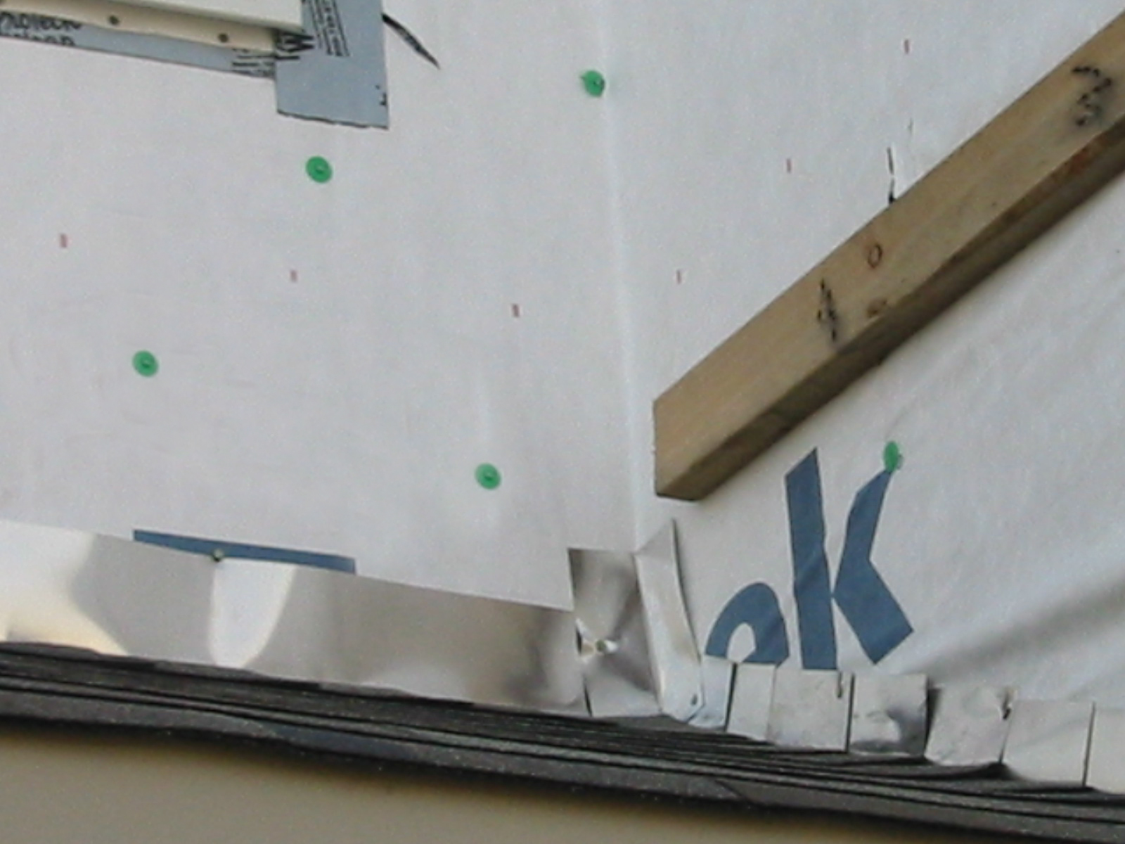
Right – The water-resistant barrier covers the entire house and the seams are taped to provide a complete drainage system
Image
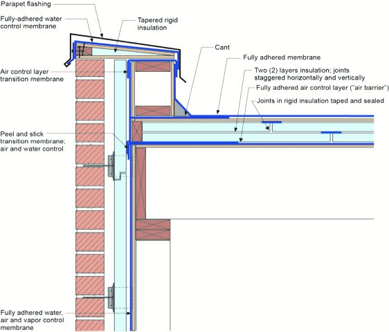
Right – This low-slope roof and parapet assembly has continuity of both the air and water barriers
Image
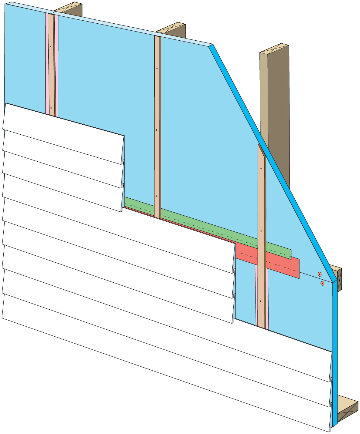
Rigid foam insulation can serve as the drainage plane when all seams are taped. Furring strips provide an air gap behind the cladding.
Image
Image
Image
Shear Strength Comparison Between a Foundation Stud Anchor (on left) and a Shear Transfer Angle (on right)
Image
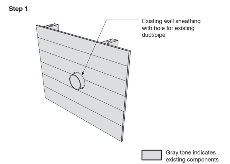
Step 1. Remove the existing wall cladding to prepare to retrofit an exterior wall.
Image
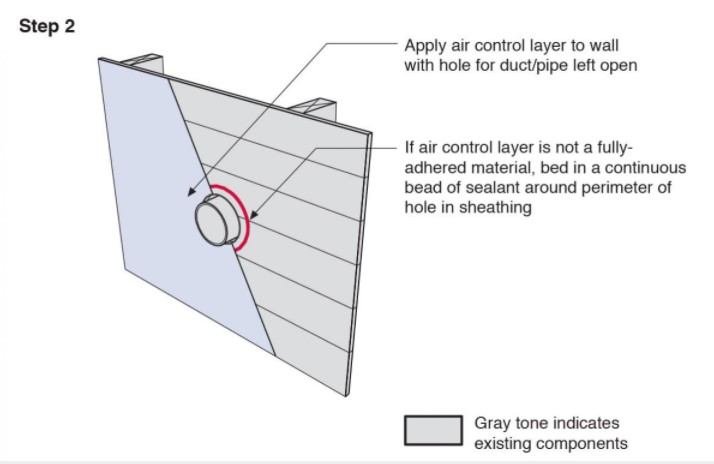
Step 2. Install a continuous air and water control layer over the existing wall sheathing.
Image
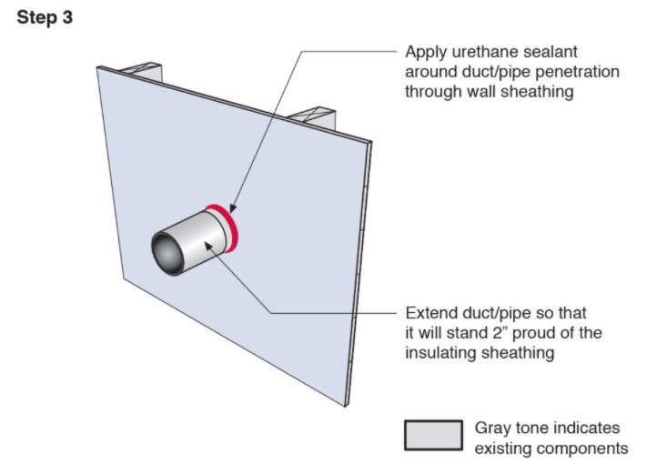
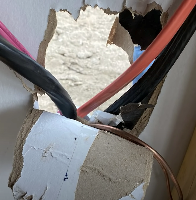
Step 3. Apply urethane sealant around the duct or pipe in the retrofitted exterior wall.
Image
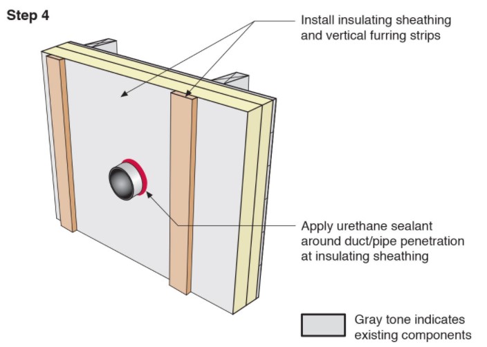
Step 4. Install insulating sheathing and vertical furring strips on the retrofitted exterior wall; seal around pipe or duct with urethane sealant.
Image
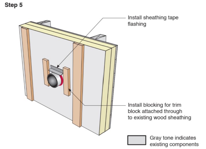
Step 5. Install sheathing tape flashing over the duct or pipe and wood blocking on either side for later attachment of trim.
Image
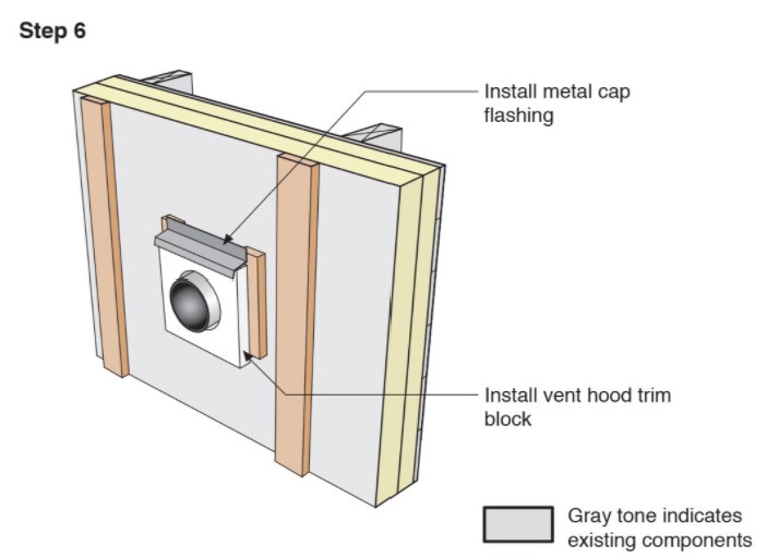
Step 6. Install vent hood trim block, metal cap flashing; seal top edge of flashing with sheathing tape.
Image
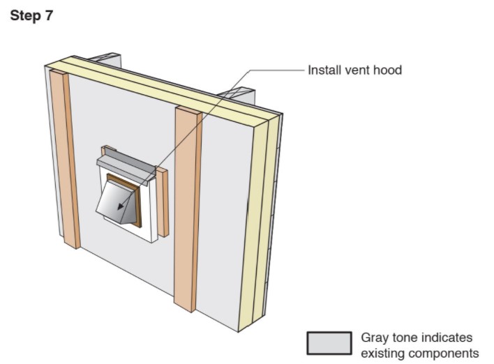
Image
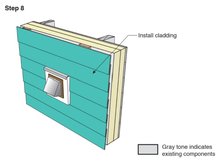
Step 8. Attach the new cladding to the furring strips over the rigid foam for the exterior wall retrofit.
Image
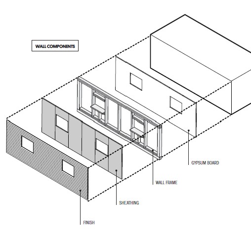
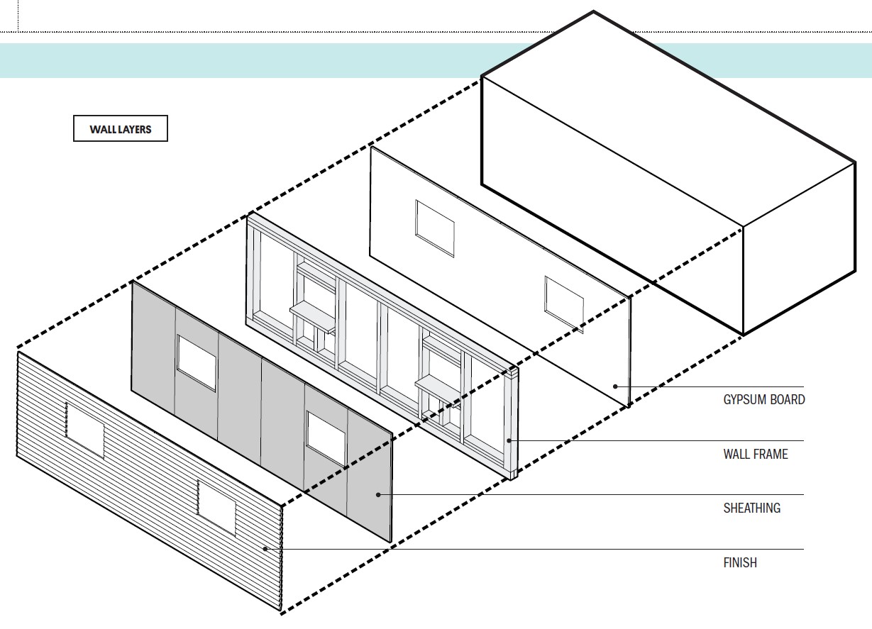
The components of a framed wall include from inside to out: gypsum, wood studs, OSB or plywood sheathing, and siding.
Image
Image
Image
Image
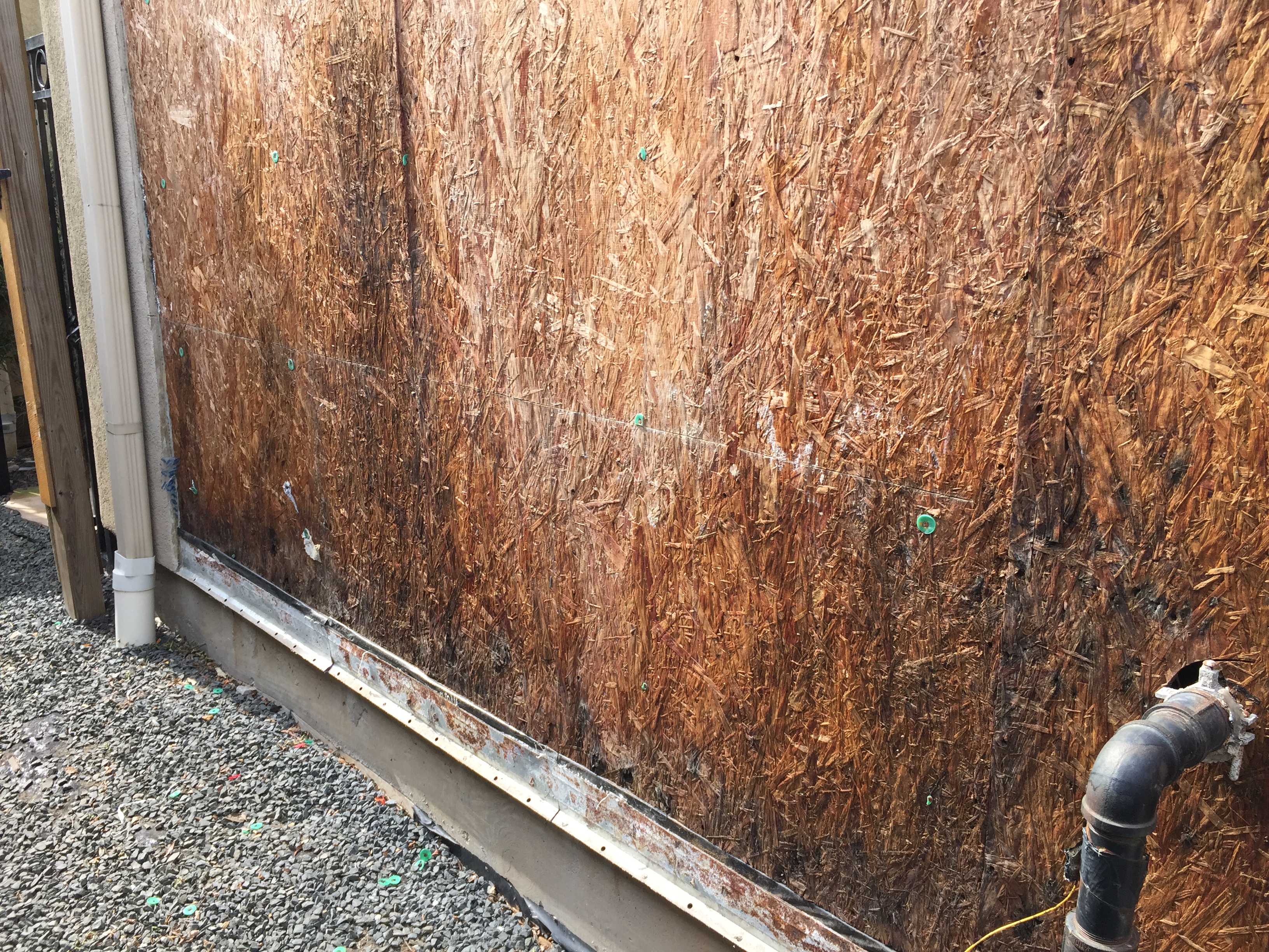
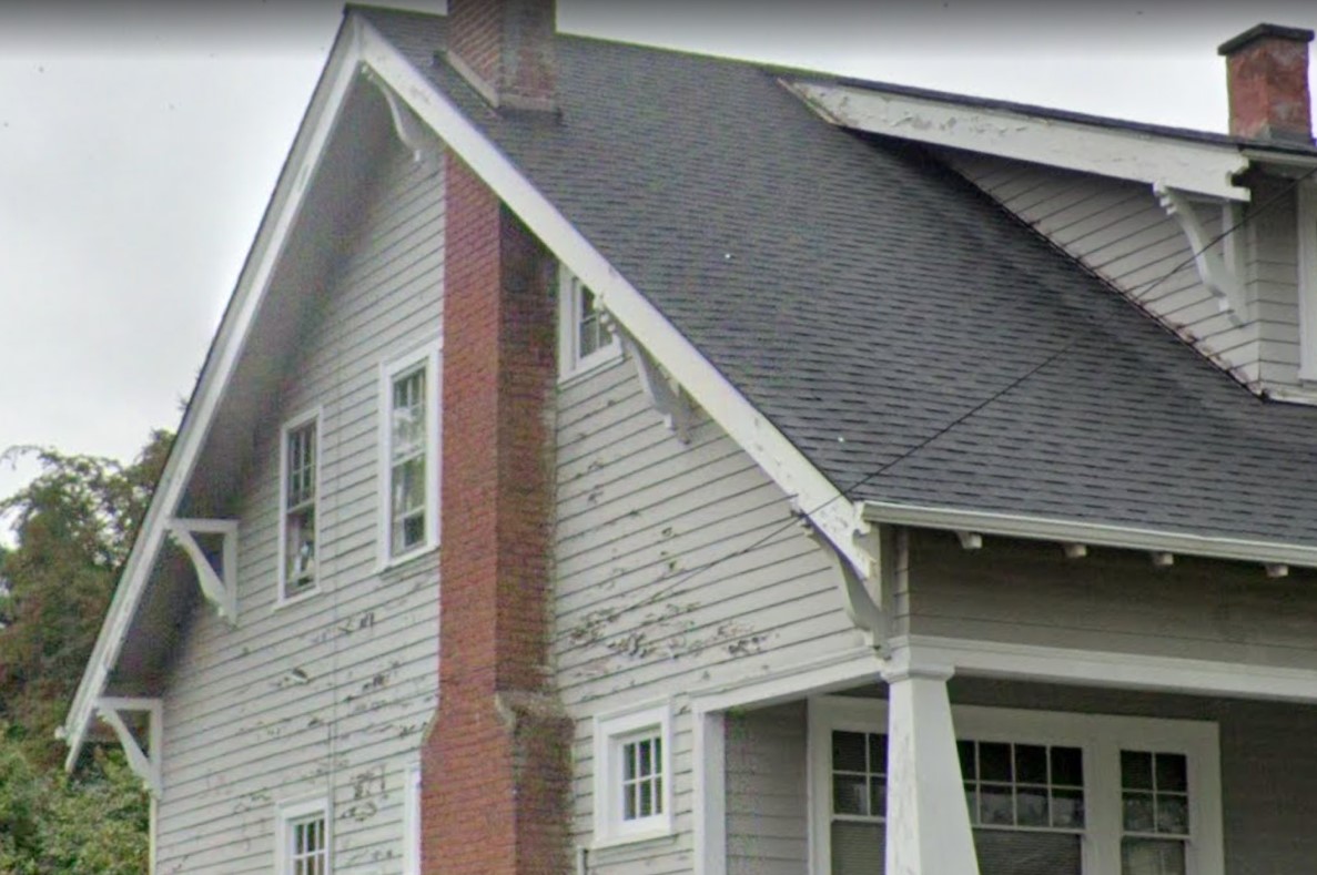
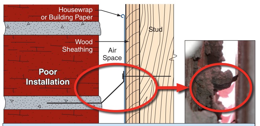
The sheathing has rotted because there was not a sufficient drainage gap behind the stucco cladding
Image
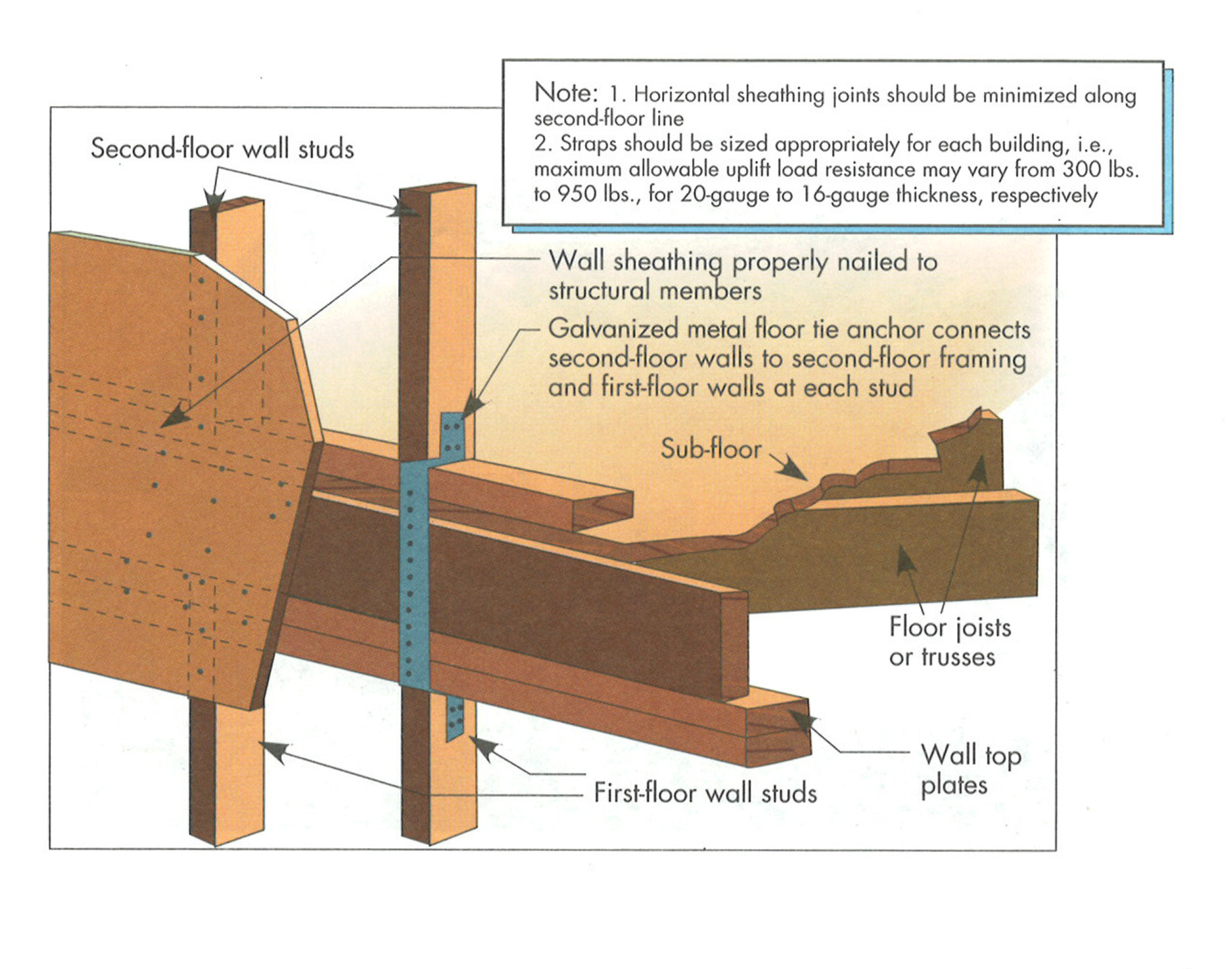
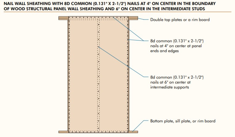
Upper-floor tie to lower floor for two-story building. Floor tie anchor and nailed wall sheathing.
Image
Image
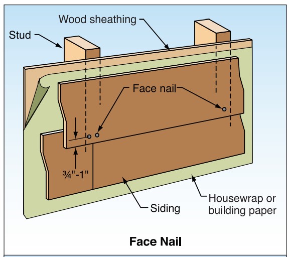
With fiber cement siding, face nail rather than blind nail where the design wind speed is ≥100 mph.
Image
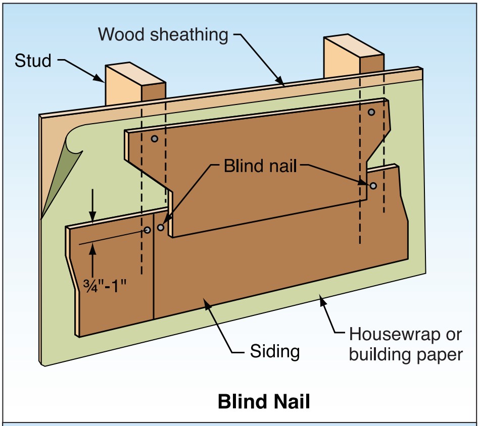
With fiber cement siding, place blind nails 3/4 to 1 inch from top edge and > 3/8 inch in from butt ends.
Image
Image
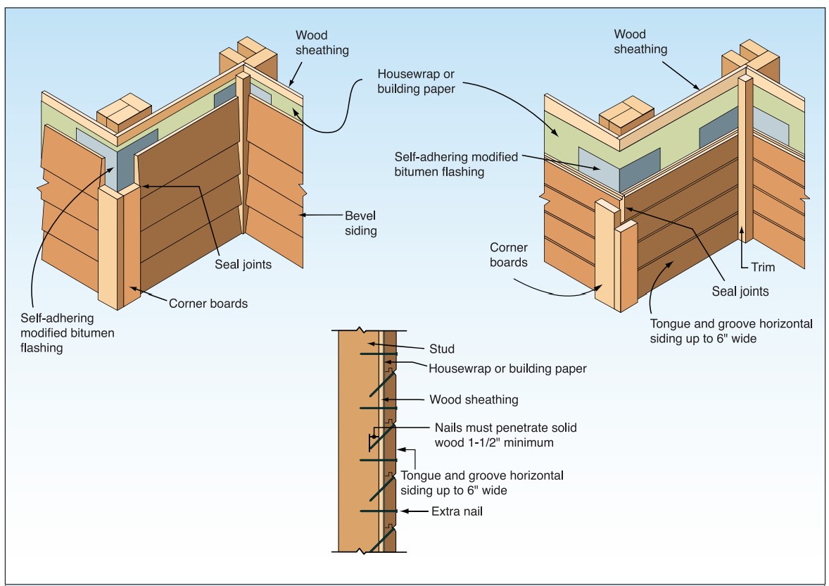
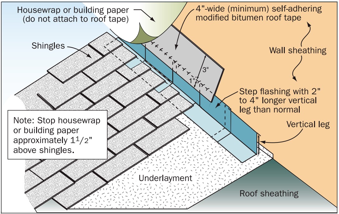
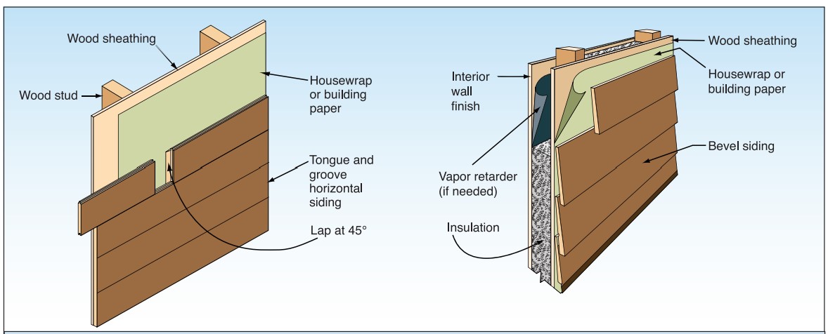
Wood siding installation details to improve resistance to wind-driven rain at corners.
Image
Wrong - During high winds air entered the home elsewhere and pushed out the door which was inadequately anchored to the wall.
Image
Wrong - Framing a dormer using only toe nailing and end nailing is not acceptable in areas subjected to high winds, hurricanes, or earthquakes.
Image
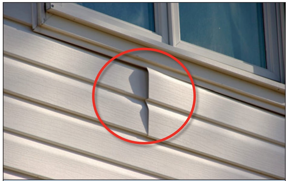
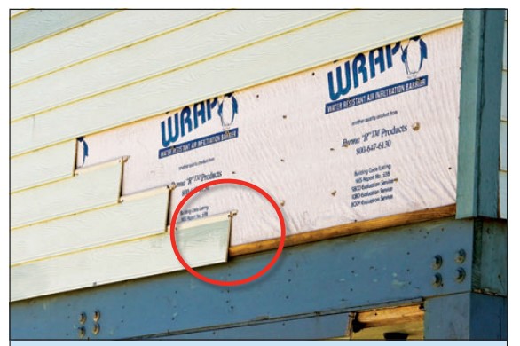
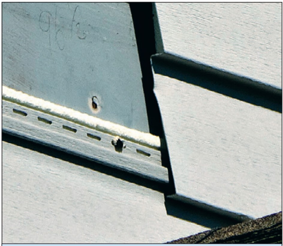
Wrong - Utility trim was substituted for the starter strip and the bottom lock was cut off this vinyl siding so the siding pulled loose under wind pressure.
Image
Wrong – For proper detailing of vinyl around windows and other obstacles, use utility trim, punch snaplocks into siding, and do not overlap directly beneath a window.
Image
Wrong – Misalignment of the tie reduces the embedment and enables the brick veneer to be pulled away.
Image
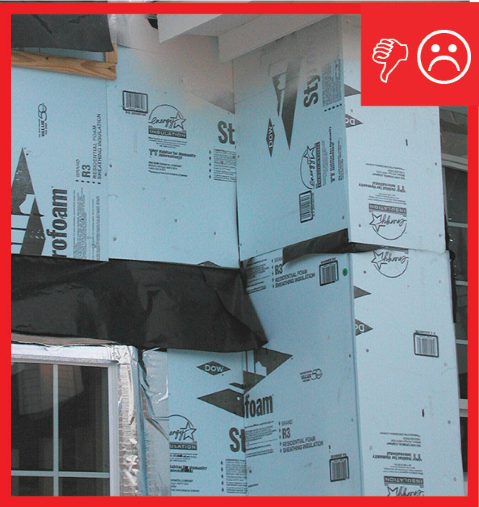
Wrong – The rigid sheathing seams are not taped and the gaps could cause moisture problems
Image

Wrong – The roof sheathing was inadequately fastened and gave way causing the gable end wall to fail
Image
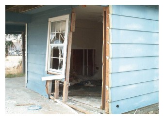
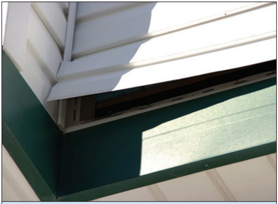
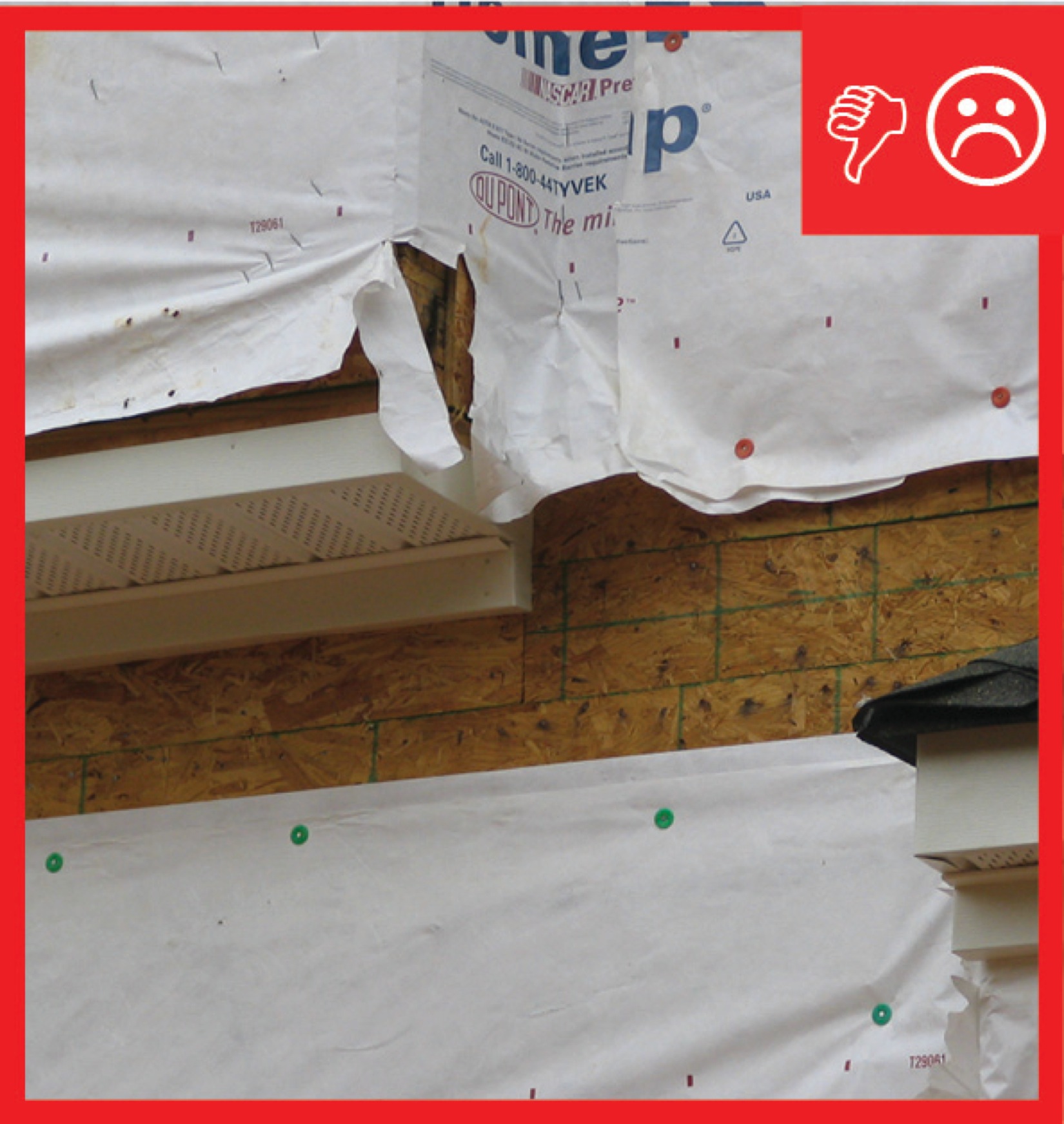
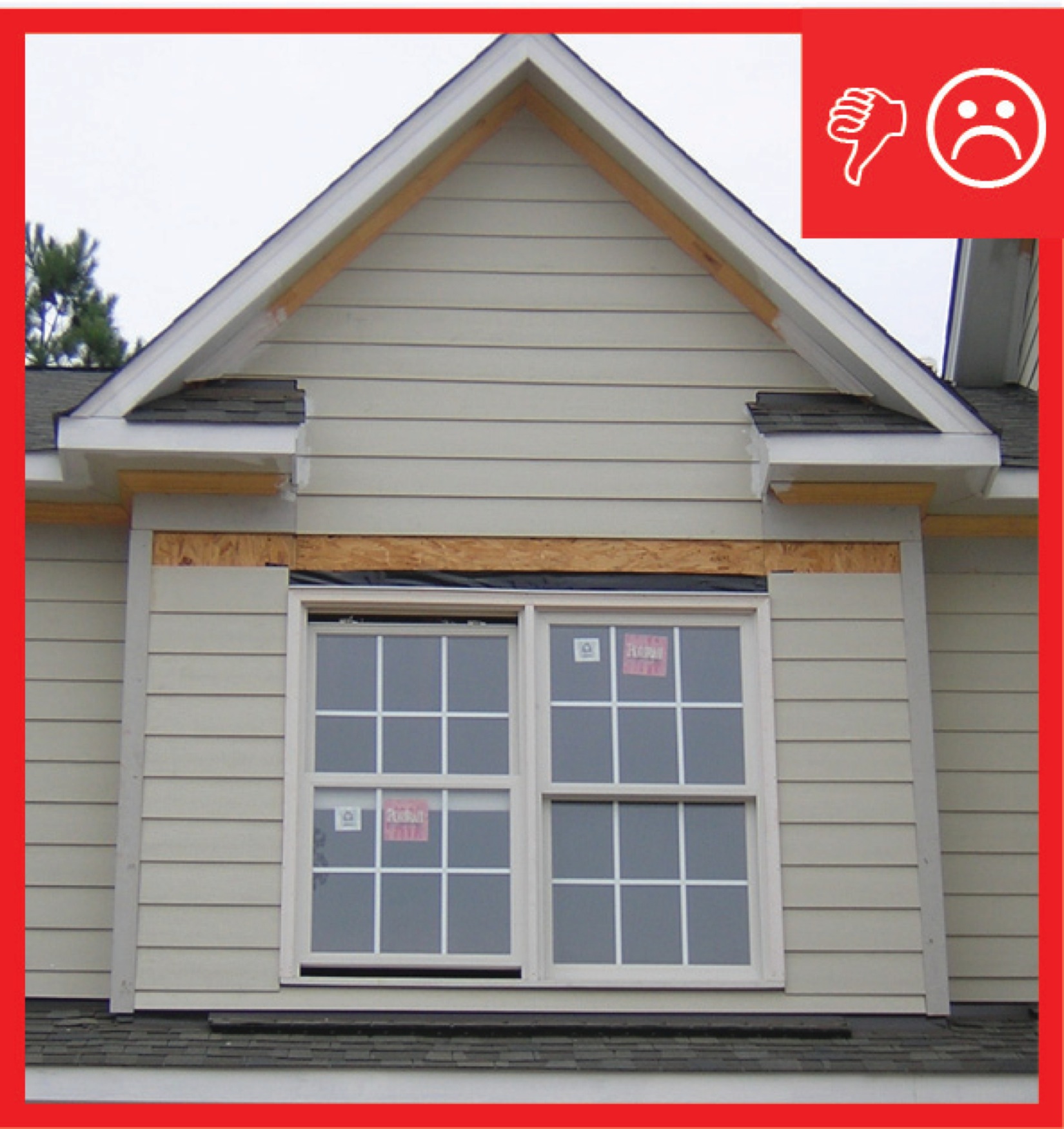
Wrong – The underside of the first course of siding extends beyond the underlying sheathing leaving it vulnerable being pulled off by pressure from high winds.
Image
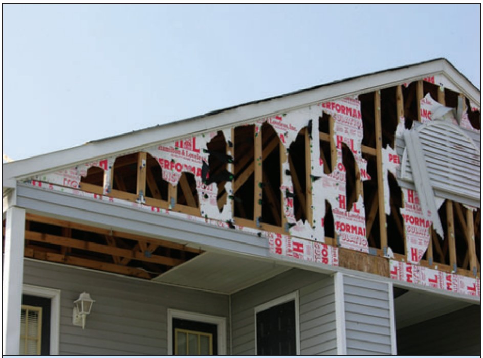
Wrong – The vinyl siding at this gable was installed over rigid foam instead of wood sheathing and neither had the structural strength to resist hurricane wind pressures.
Image
Image
Wrong – The water-resistant barrier is not complete and the holes and gaps could cause moisture problems
Image
Wrong – There is not a water-resistant barrier installed underneath the exterior finish of the walls
Image
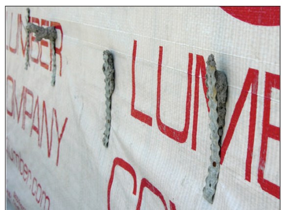
Wrong – These four ties were never embedded into the mortar joint, allowing the brick wall to be pulled away from the sheathing.
Image
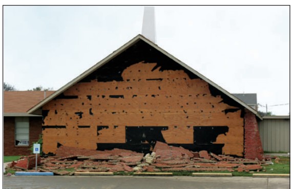
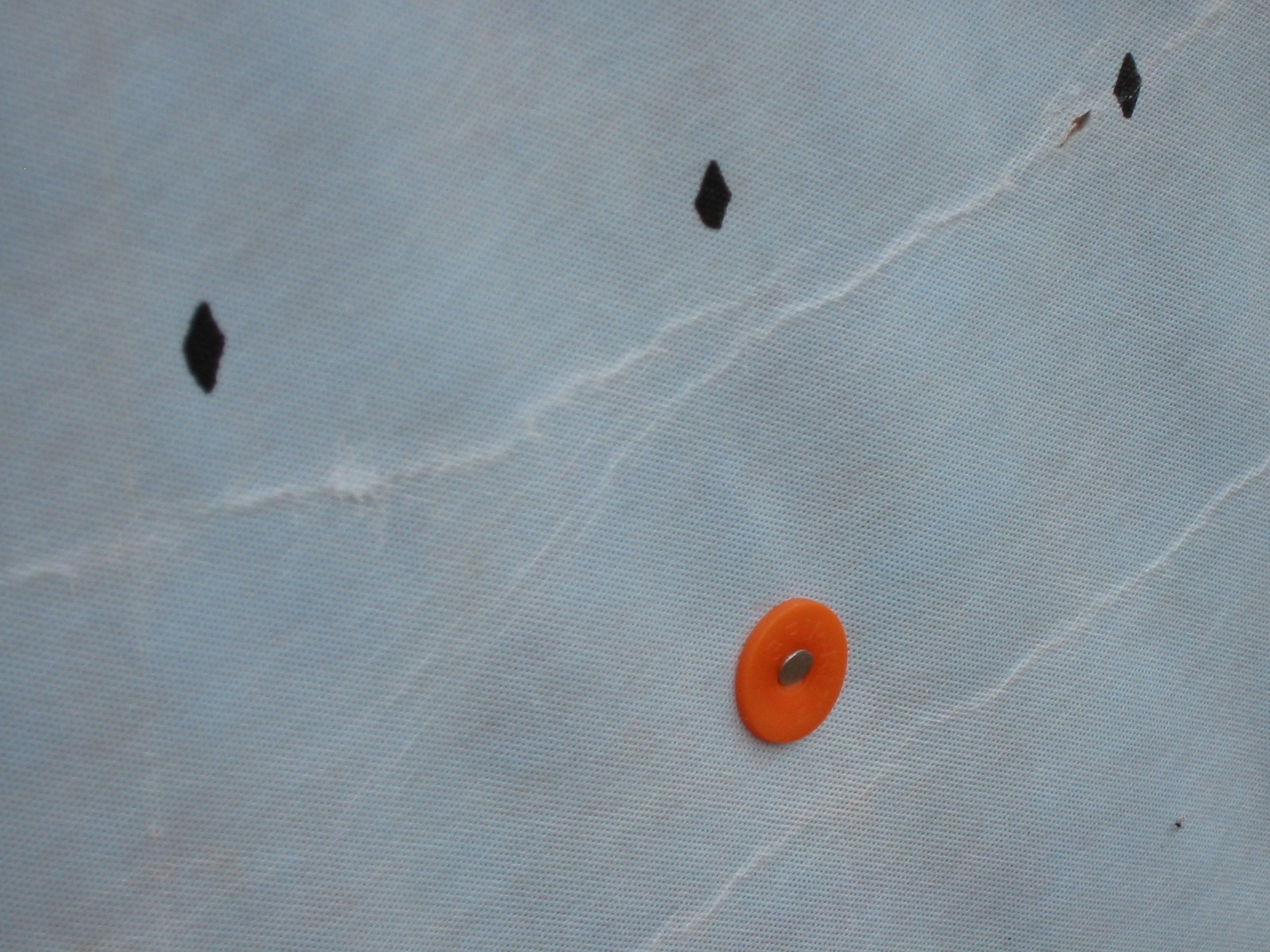
Wrong – This brick veneer failed in high winds (107 mph) because the ties pulled out of the substrate.
Image
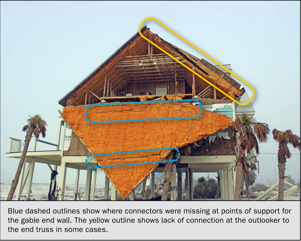
Wrong – This gable end wall failed because connectors were missing at points of support (blue circles) and the outlookers were not connected to the end truss (yellow circle)
Image
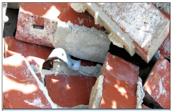
Wrong – This metal tie remained embedded in the mortar joint but the smooth-shank nail pulled out from the stud.