Showing results 1 - 43 of 43
Image
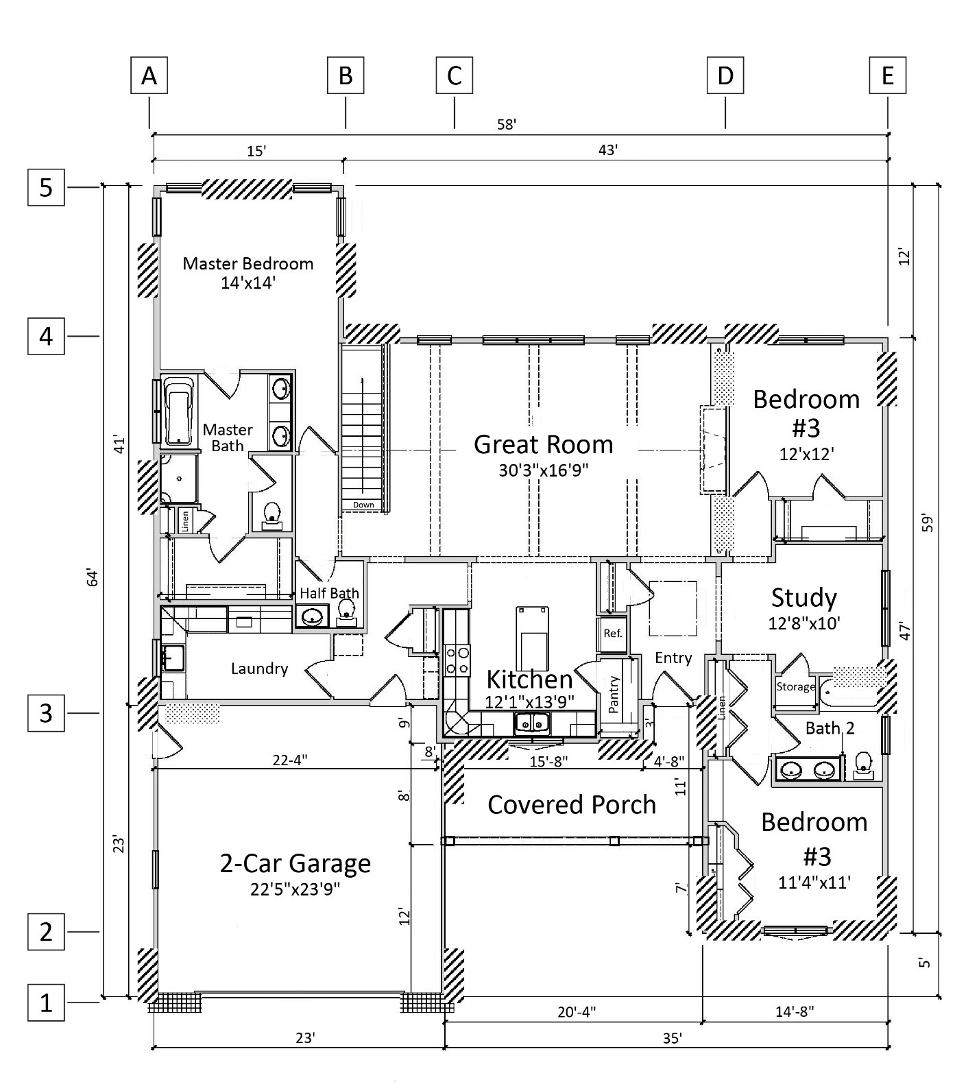
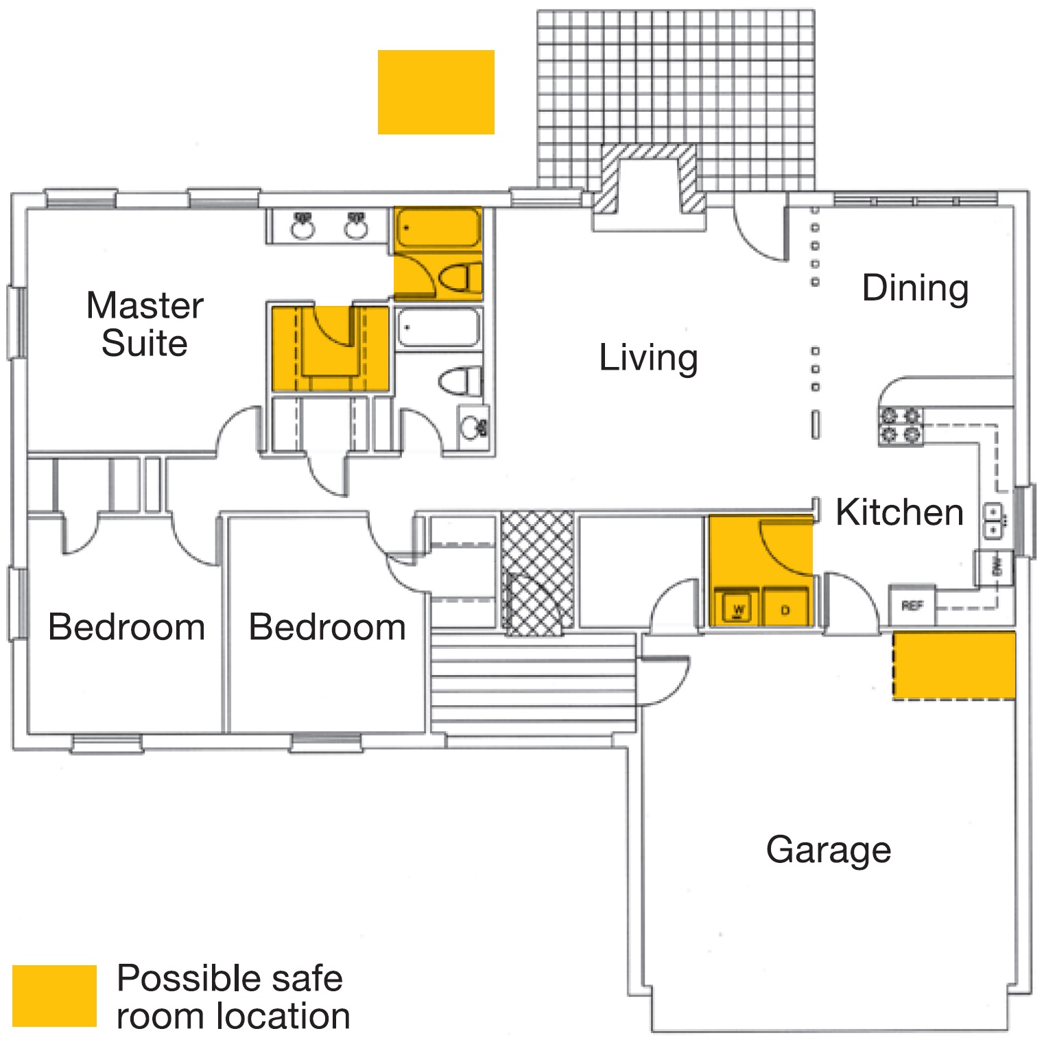
A single-story house floor plan showing braced wall line locations at A through E and 1 through 5
Image
Image
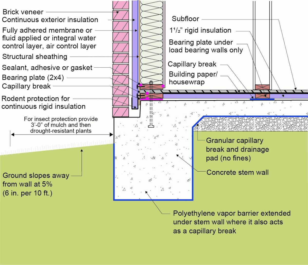
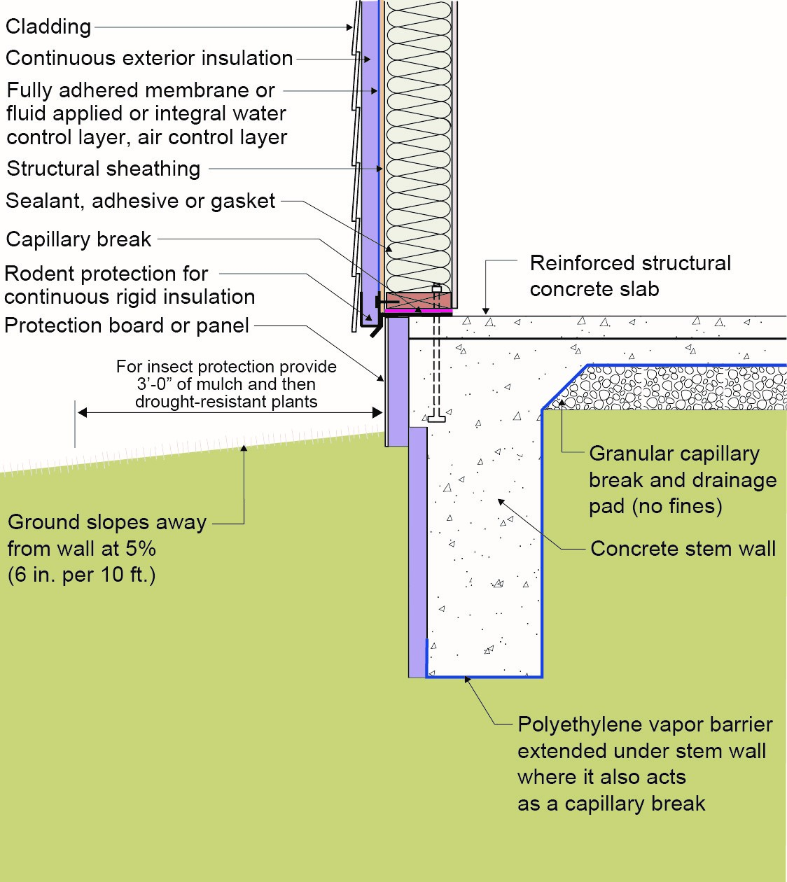
Brick veneer framed wall supported by a concrete slab-on-grade foundation with a turn-down footing insulated on its top surface, showing anchorage of the wall to the foundation for seismic resistance
Image
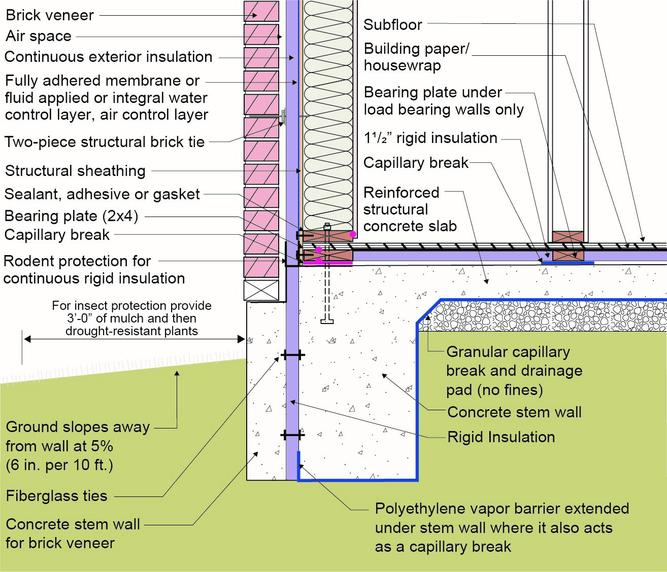
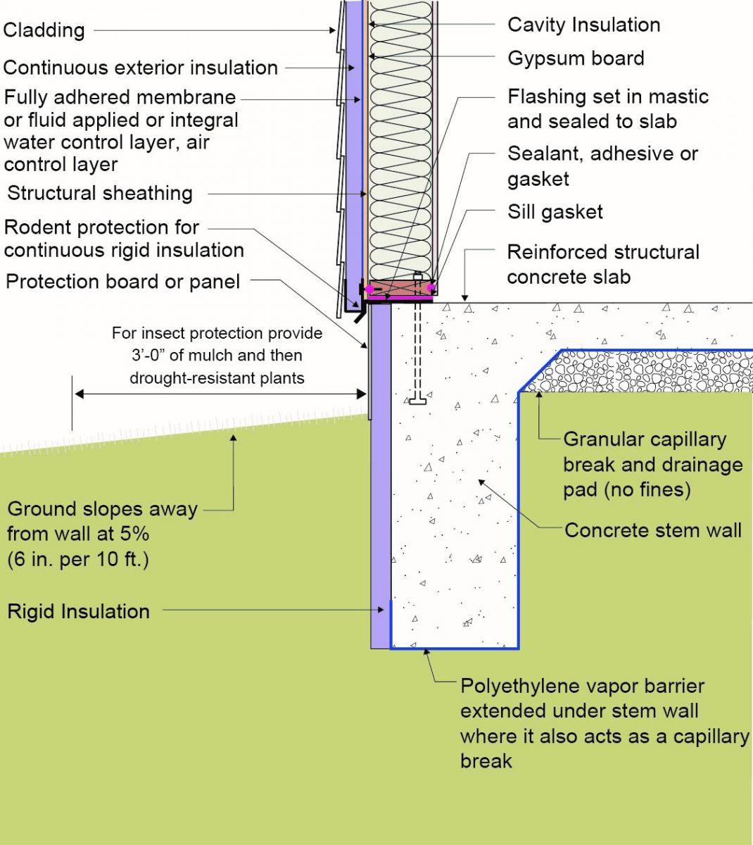
Brick veneer is supported by a concrete stem wall thermally separated from the slab-on-grade foundation with turn-down footing which is also insulated on top; anchorage for seismic resistance is also shown
Image
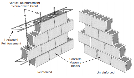
CMU construction can be reinforced with vertical rebar and horizontal steel reinforcement (left) or unreinforced (right), depending on structural requirements
Image
Concrete slab-on-grade foundation with a turn-down footing insulated on its top surface, showing anchorage of the wall to the foundation for seismic resistance
Image
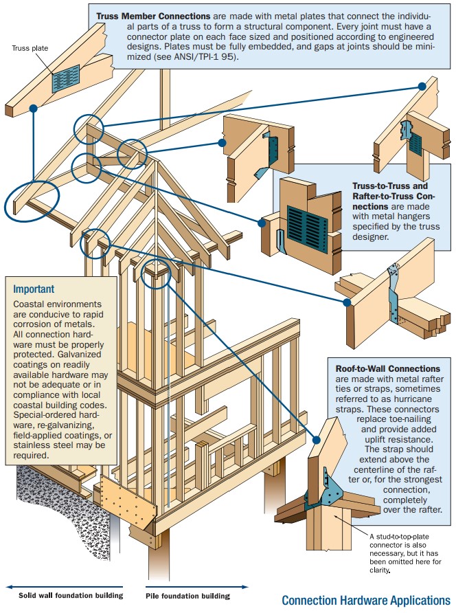
Connecting hardware helps tie the roof to the walls to ensure a continuous load path to improve a building’s resistance to high winds, floods, and earthquakes.
Image
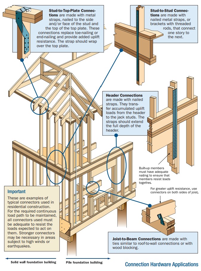
Connecting hardware helps tie the walls to the top plates and rim joists to ensure a continuous load path to improve a building’s resistance to high winds, floods, and earthquakes.
Image
Correct seismic retrofit hardware for securing the sill plate to foundation wall
Image
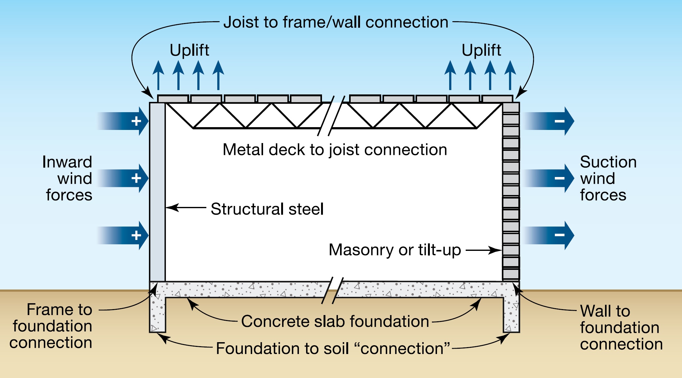
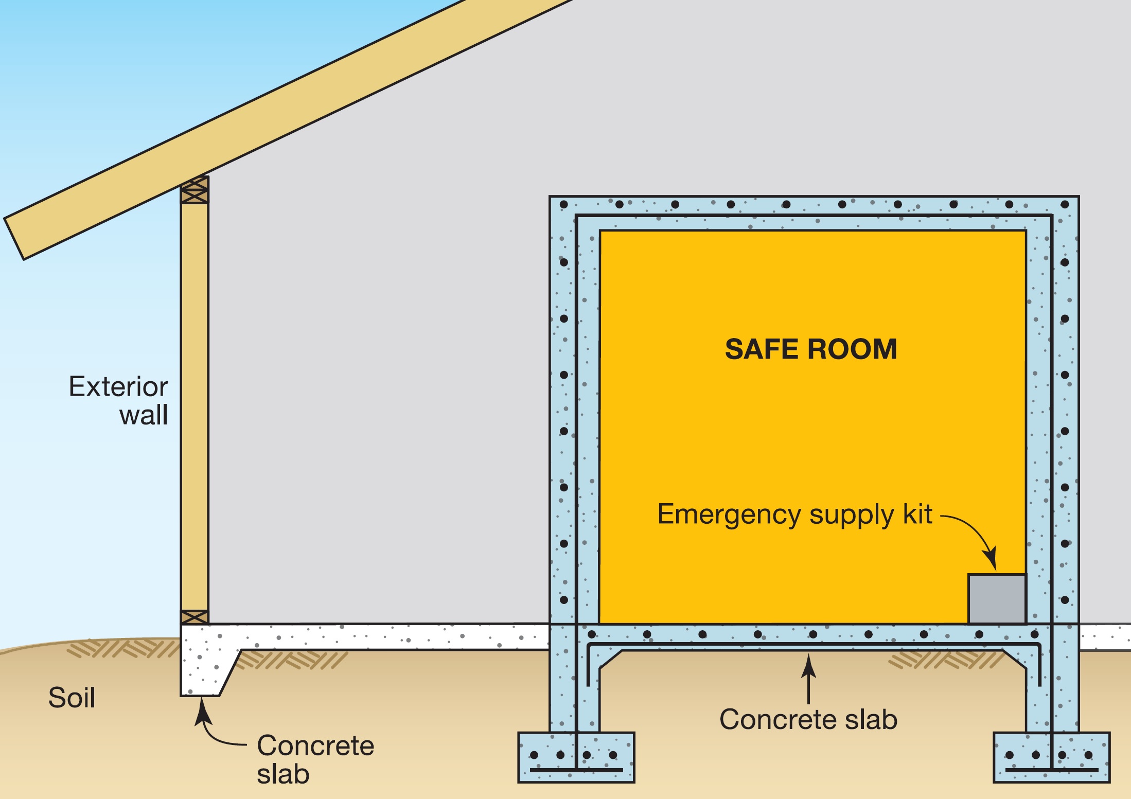
Critical connections for providing a continuous load path in buildings and storm shelters
Image
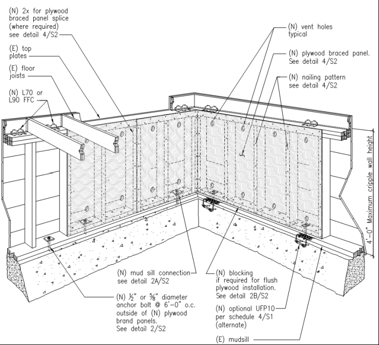
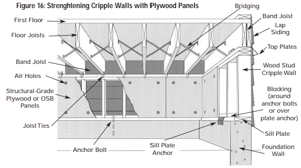
Detail for reinforcing a cripple wall to resist earthquake movement by installing anchor bolts and plywood reinforcement.
Image

Durability concerns on a house continuously sheathed with a proprietary fiber structural panel used as bracing. Photo 1 of 2.
Image
Durability concerns on a house continuously sheathed with a proprietary fiber structural panel used as bracing. Photo 2 of 2.
Image
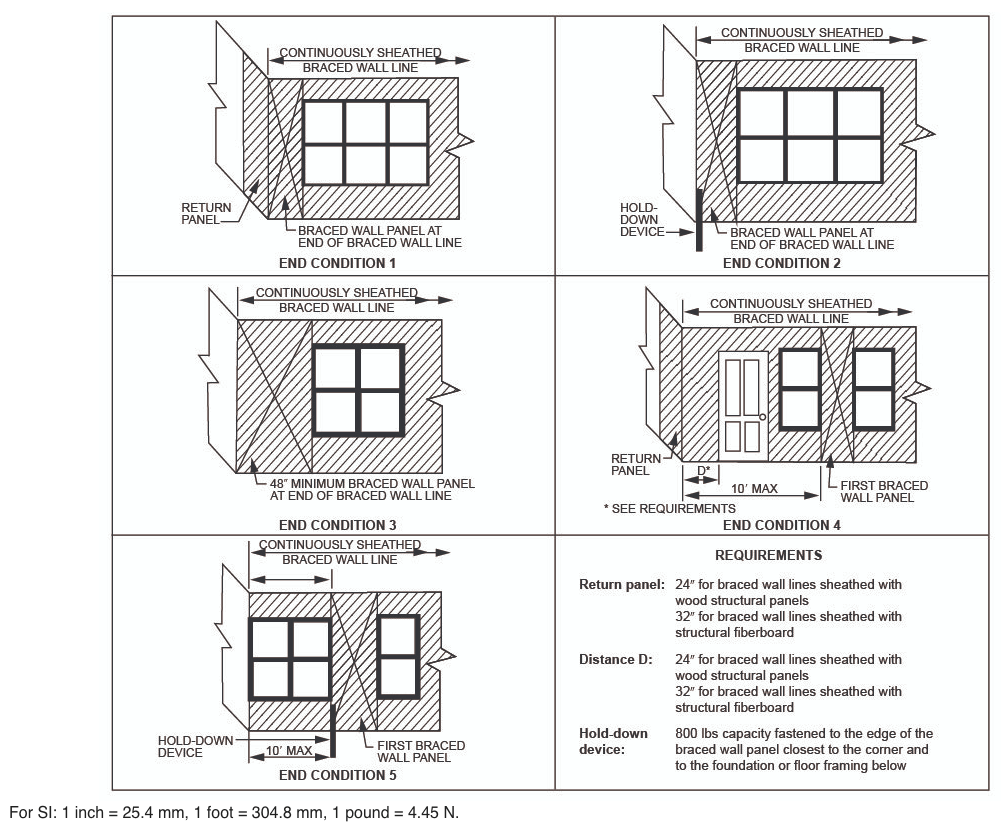
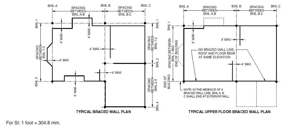
End conditions for braced wall lines with continuous sheathing, Figure R602.10.7 in the IRC
Image
Externally insulated concrete slab-on-grade foundation with a turn-down footing, showing anchorage of the wall to the foundation for seismic resistance
Image
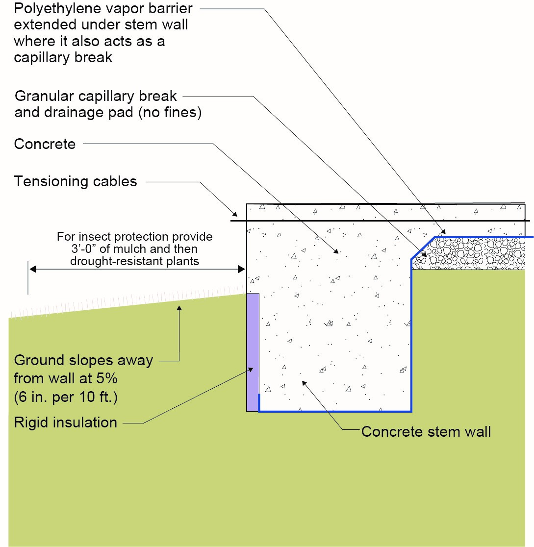
Externally insulated post-tensioned concrete slab-on-grade foundation wall with a turn-down footing showing anchorage of the wall to the foundation for seismic resistance
Image
Externally insulated post-tensioned concrete slab-on-grade foundation wall with a turn-down footing showing anchorage of the wall to the foundation for seismic resistance
Image
Image
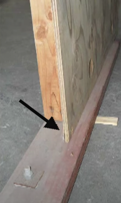
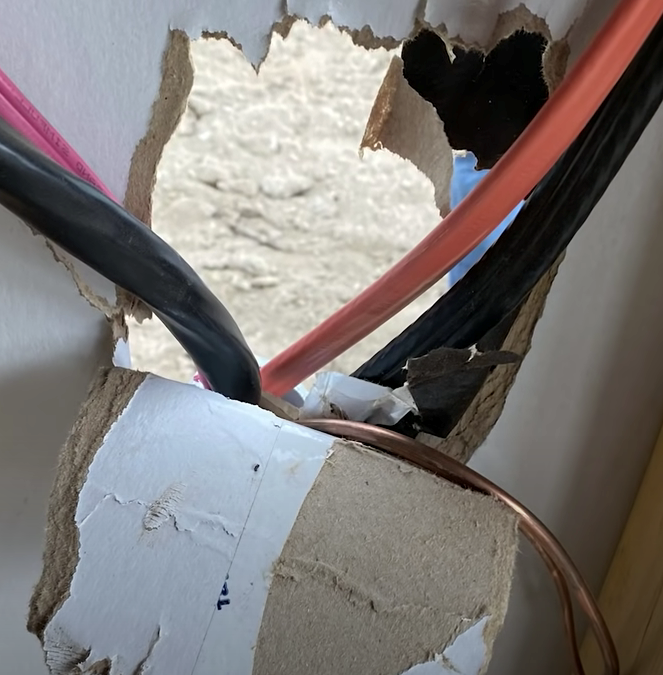
Incorrectly done seismic retrofit, the plywood sheathing is not nailed to the mud sill and therefore it is not providing any shear strength
Image
Image
Image
Image
Image
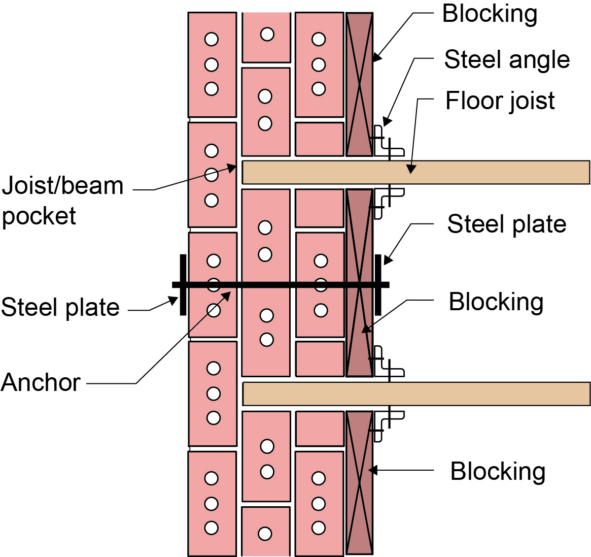
Plan view showing seismic strengthening of brick wall by anchoring the embedded wood floor joists with solid wood blocks attached to the floor joists with steel angles and to the masonry wall with through-wall anchors and steel plates
Image
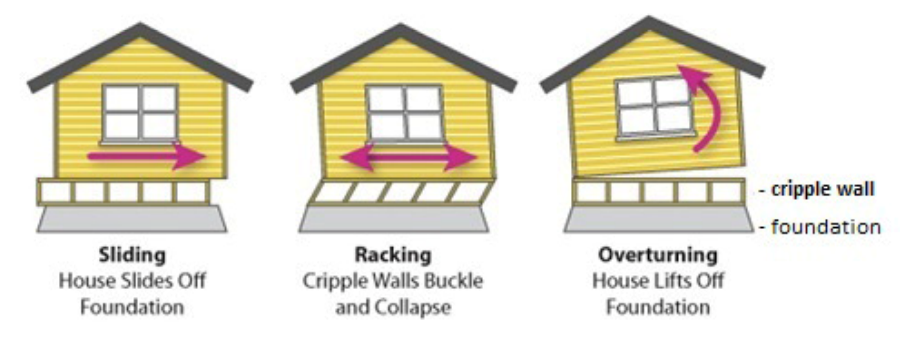
Possible failure scenarios due to house sitting on poorly braced and secured cripple wall
Image

Right - Braced wall line spacing is correctly calculated for determining wall bracing in accordance with the IRC.
Image

Right - Engineered portal frames are used for wall bracing to resist wind and earthquake loads.
Image
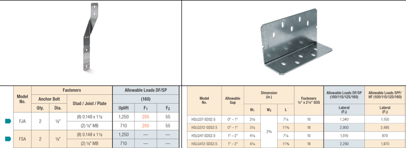
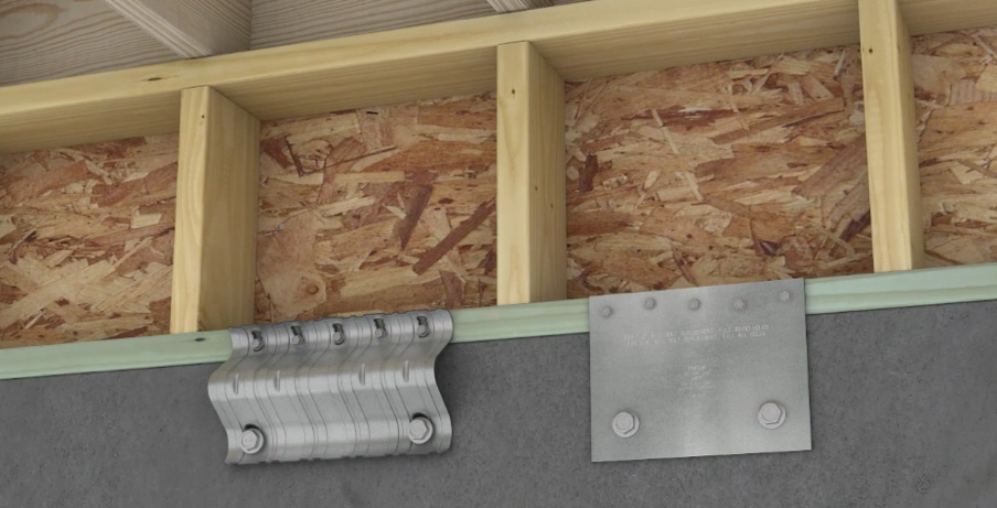
Shear Strength Comparison Between a Foundation Stud Anchor (on left) and a Shear Transfer Angle (on right)
Image
Image
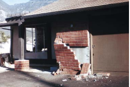
The brick veneer lacked adequate ties to keep the brick from peeling off the wall in an earthquake.
Image

The cripple wall hiding the post-and-pier foundation of this wood framed house toppled when the house was shifted partially off its piers by an earthquake
Image
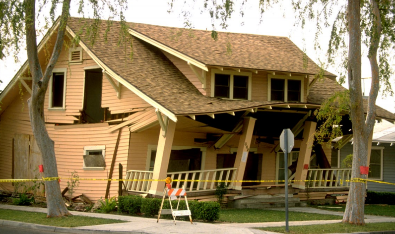
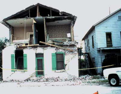
The cripple walls in this home gave way in the 1994 Northridge Earthquake, causing the walls to partially collapse.
Image
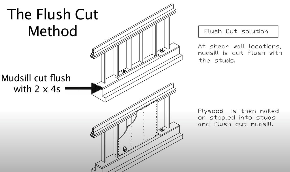
The flush cut method for seismic retrofit bracing of a cripple wall allows the plywood sheathing to be attached directly to both the cripple studs and the notched section of the mudsill
Image
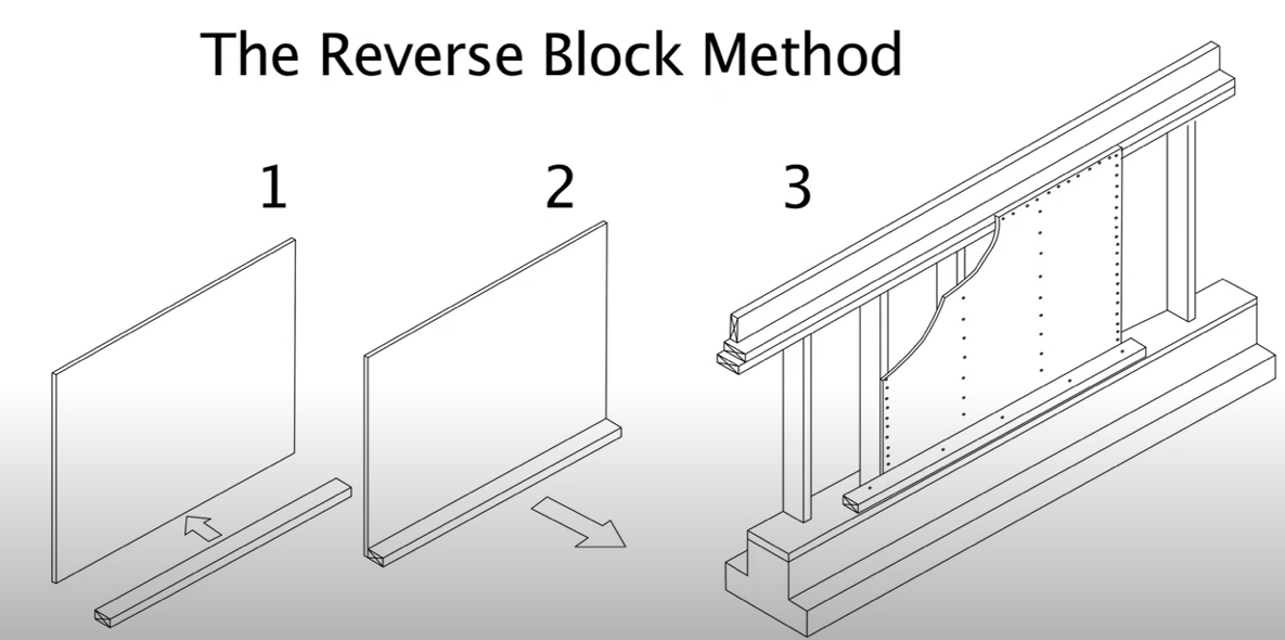
The reverse block method for seismic retrofit bracing of a cripple wall uses a 2x4 attached to the sill plate to provide a means to attach the plywood cripple wall sheathing to the sill plate
Image
Image
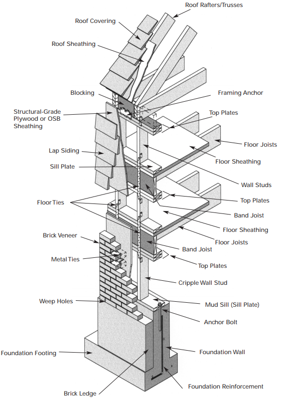
This wood-framed wall is connected with framing anchors, metal strapping and ties, and anchor bolts to secure the roof to the walls and walls to the foundation
Image

Three types of foundation walls: Stem-plus-wood stud cripple wall, reinforced concrete wall, and reinforced concrete block/masonry wall
Image
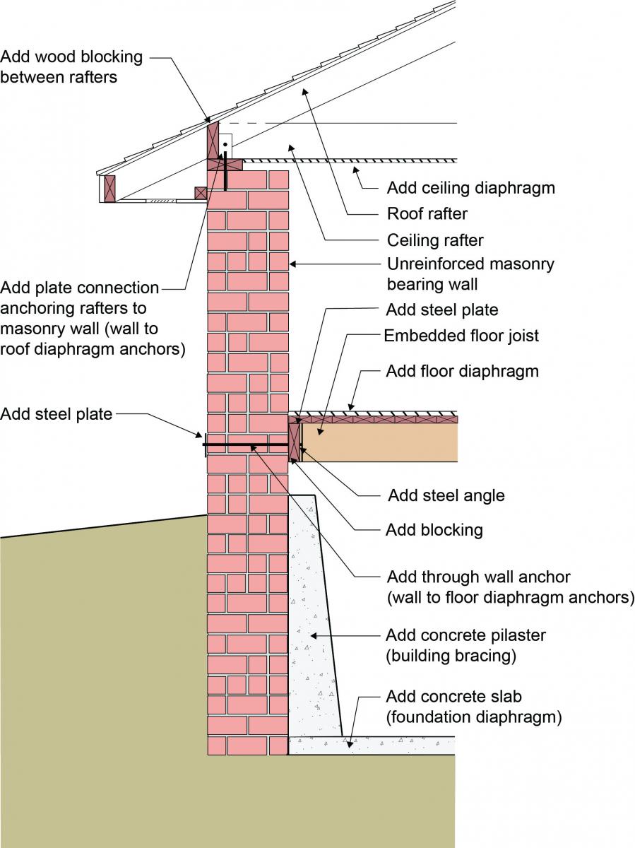
To increase a masonry-walled home’s resistance to seismic forces, solid wood blocking is added between the roof rafters, anchors are added to connect the brick wall to the rafters and floor joists, building diaphragms are added, foundation braced
Image
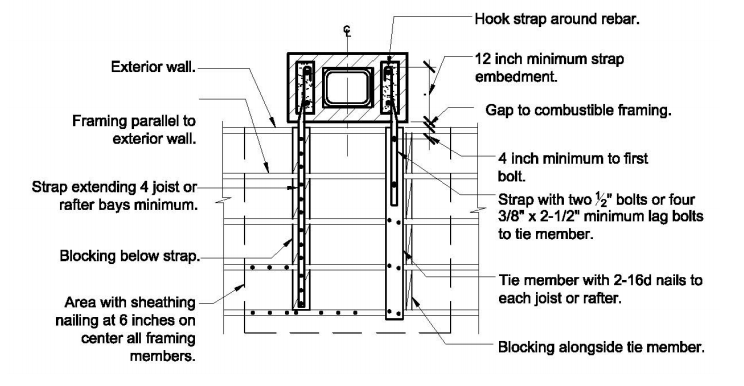
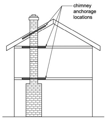
Top view showing how the chimney is attached to at least four ceiling joists running parallel to the exterior wall.
Image
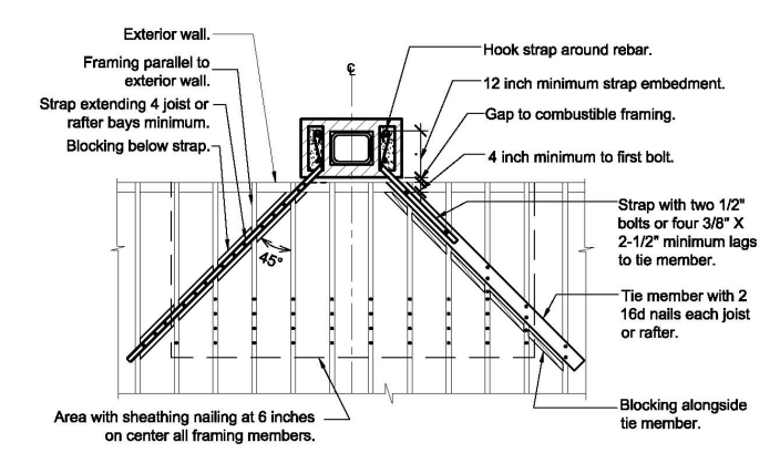
Top view showing how the chimney is attached to ceiling joists that run perpendicular to the exterior wall.
Image
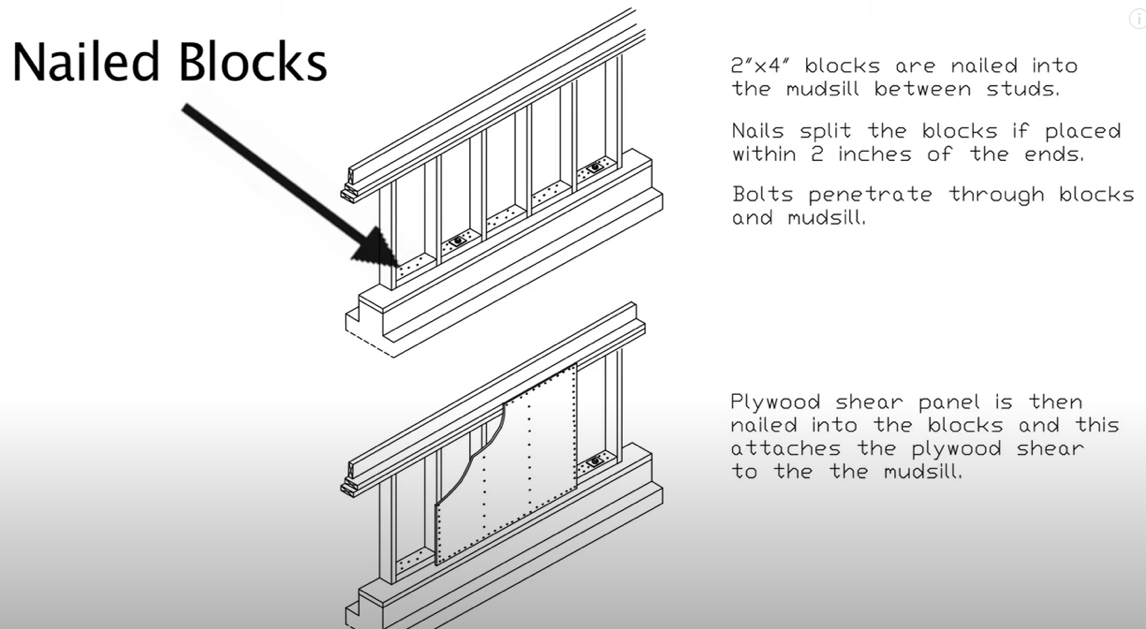
With the nailed block method, wood blocks are attached to the sill plate and the cripple wall plywood is attached to the block to provide shear strength for correctly bracing a cripple wall in a seismic retrofit
Image
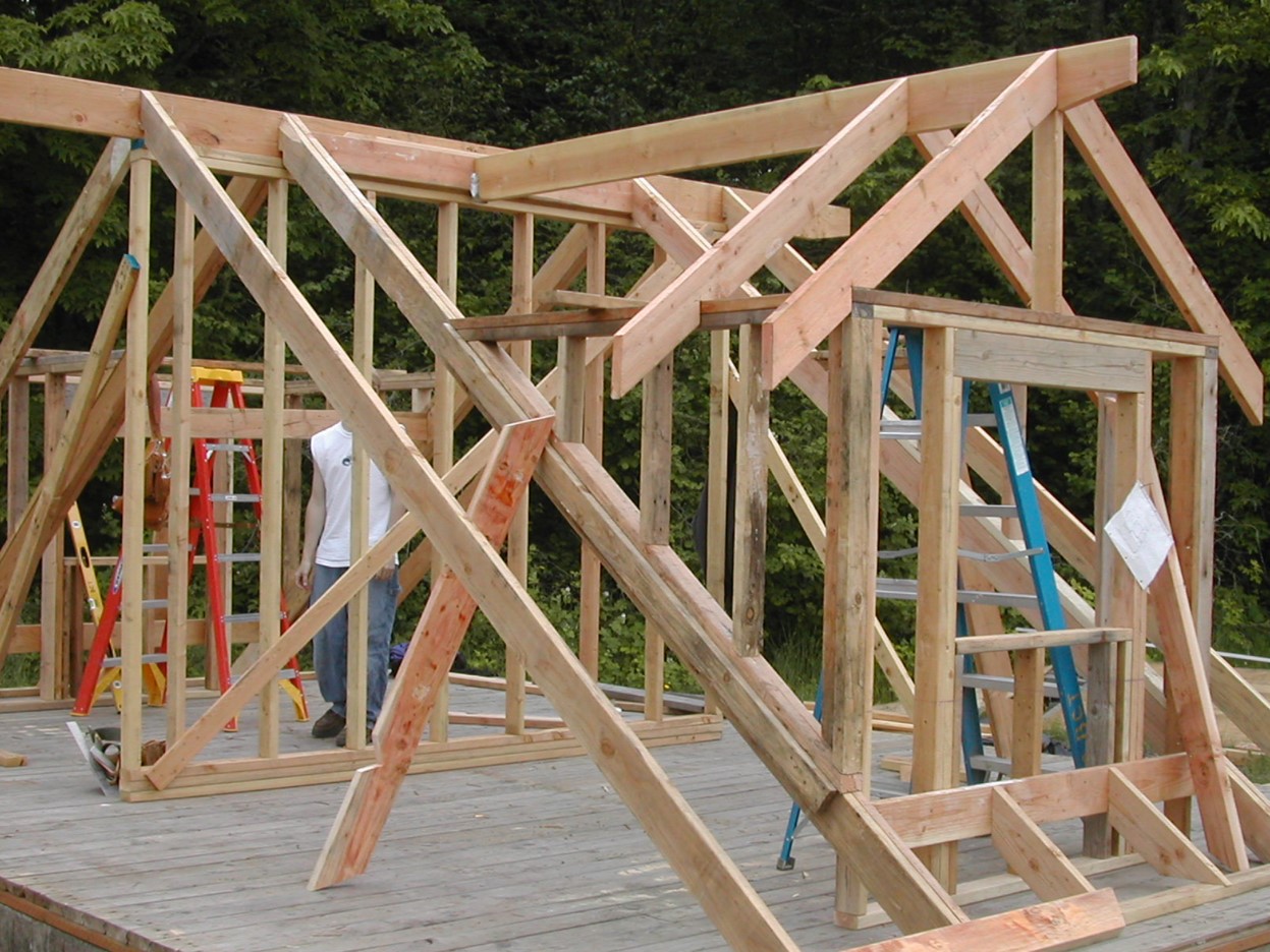
Wrong - Framing a dormer using only toe nailing and end nailing is not acceptable in areas subjected to high winds, hurricanes, or earthquakes.
Image