Showing results 701 - 750 of 1165
Image
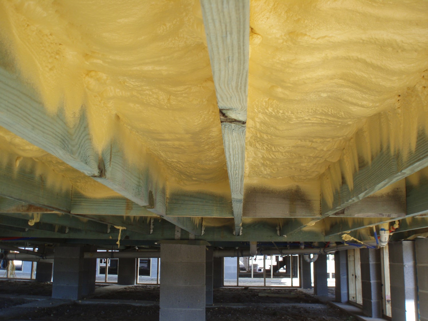
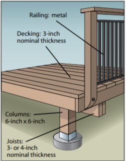
Right – This floor system on a column foundation is insulated using closed-cell spray foam rather than fibrous insulation
Image
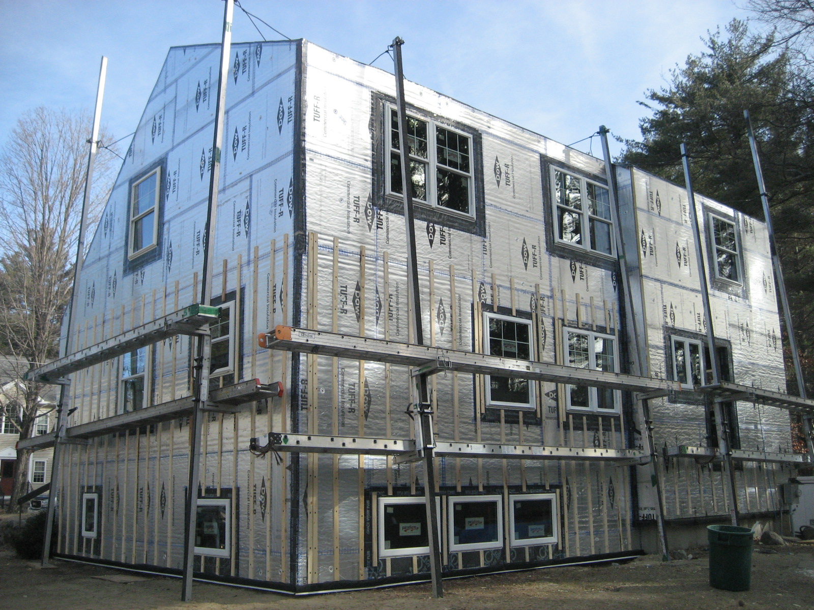
Right – This foil-faced foam sheathing has taped seams and proper flashing details so it can serve as a drainage plane.
Image
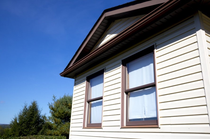
Right – This home uses a light-colored exterior wall to reduce solar heat gain
Image
Image
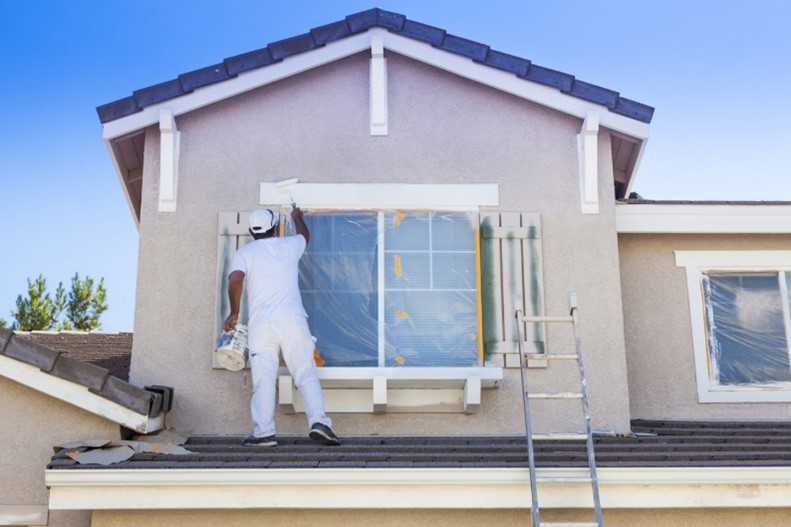
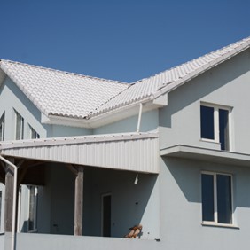
Right – This home uses light tan stucco and white trim to reduce solar heat gain.
Image
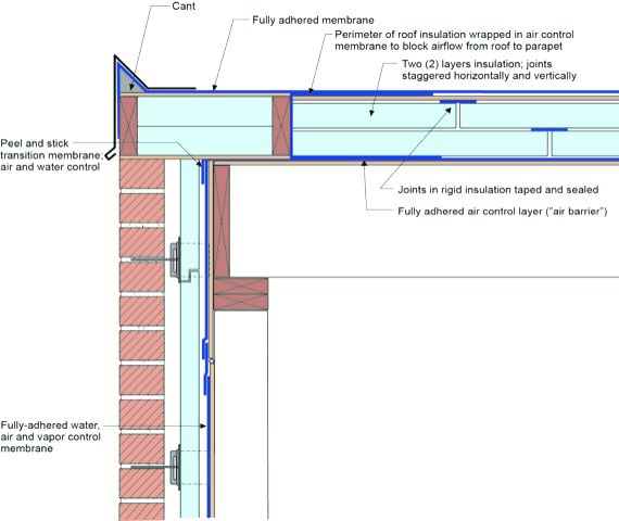
Right – This low-slope flat roof assembly has continuity of both the air and water barriers
Image
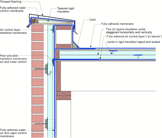
Right – This low-slope roof and parapet assembly has continuity of both the air and water barriers
Image
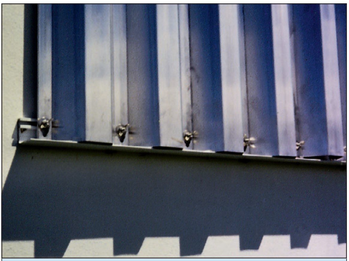
Right – This metal panel window shutter is installed in a track permanently mounted above and below the window frame and is secured with wing nuts to studs mounted on the track.
Image
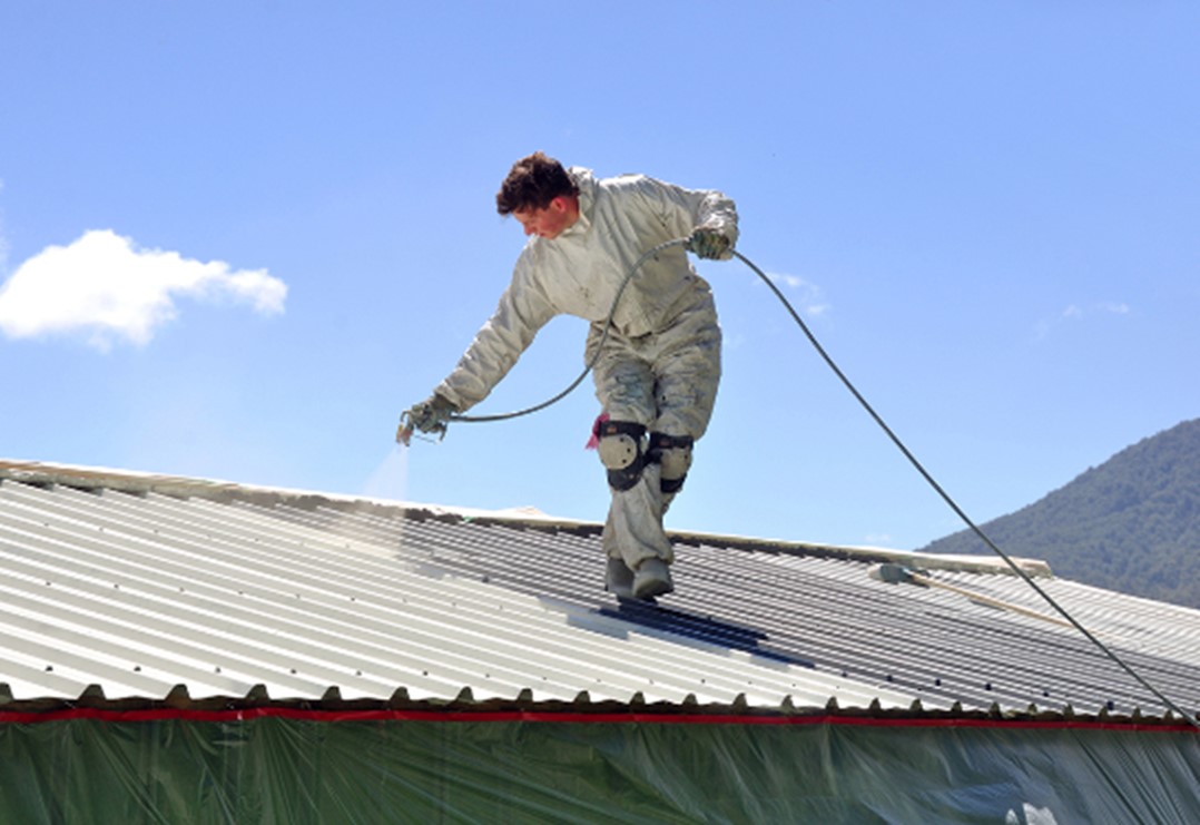
Right – This metal roof is being coated with a cool (high SRI) coating to reduce solar heat gain
Image
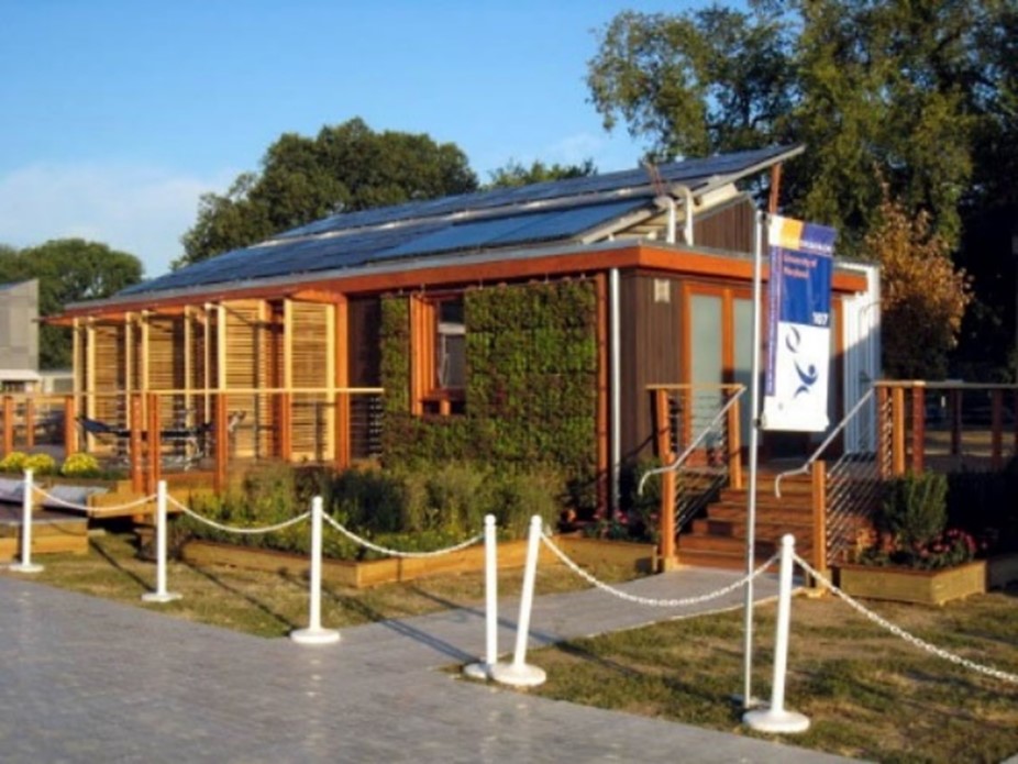
Right – This model home for the Solar Decathlon competition incorporates vertical trellises and retractable exterior blinds to control solar heat gain.
Image

Right – This shrub has been pruned to allow views out the windows of this home while providing shade to walls, windows, and roof.
Image

Right – This swale has sloped sides with appropriate vegetation to filter rainwater.
Image
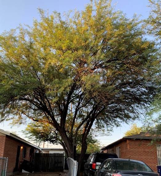
Right – This tree shades walls, windows, roofs, and grounds for two adjacent homes.
Image
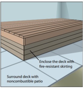
Right – To make decks more fire-resistant, enclose the bottom of the deck with a non-flammable skirt, and surround the deck with a non-flammable surface like pavers.
Image
Right – To make decks more resistant to fires, for floor joists and beams, use heavy fire-retardant-treated timbers, concrete, or steel framing; for decking and stair treads, use treated wood, brick, or concrete pavers; and for railings, use treated wood,
Image

Right – Trimming tree branches a minimum of 10 feet from the house or any attached structures reduces the risk of home ignition.
Image

Right – Trimming tree canopies a minimum of 10 feet from the house reduces the risk of home ignition.
Image
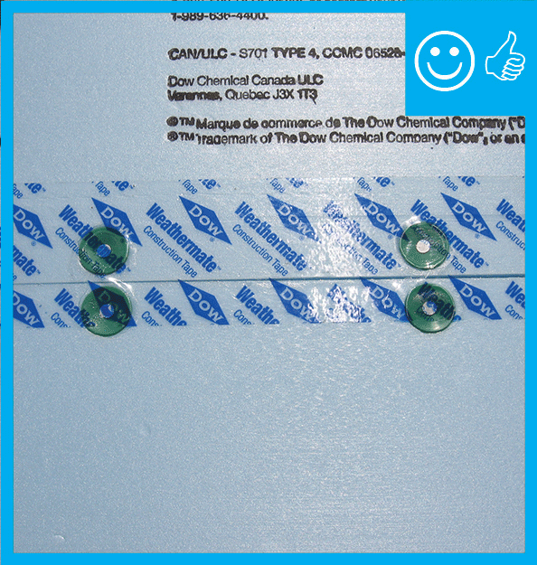
Right – Two-thirds of acrylic tape is offset above the joint and over and above the fasteners
Image
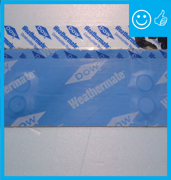
Right – two-thirds of the blue butyl flashing tape is above the sheathing seam; the top edge of the butyl flashing tape is covered with clear sheathing tape that is also offset so two-thirds is above the top edge of the butyl flashing.
Image
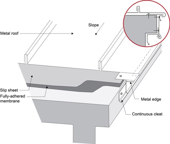
Right – Under metal roofing, sheathing is protected by metal edging over a fully adhered membrane and a slip sheet of loose laid building paper
Image
Image

Right – Weatherstripping has been installed and remains in contact when the door is closed.
Image
Right- Landscaping shades the entry on the south west corner of this hot dry climate building.
Image
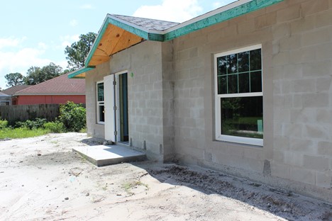
Right- This house uses CMU construction for flood and termite resistance as well as thermal mass
Image
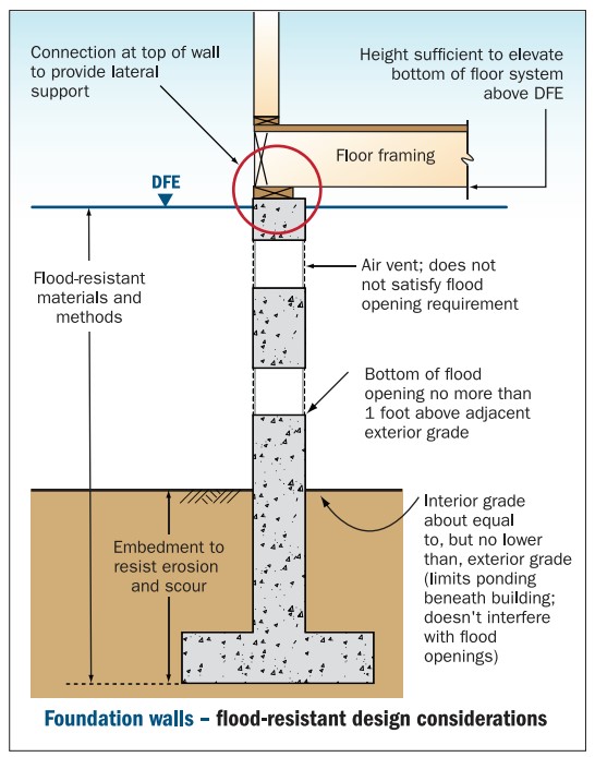
Right-Flood resistant foundation walls lift the floor framing above the DFE and include flood openings to let flood waters pass through.
Image
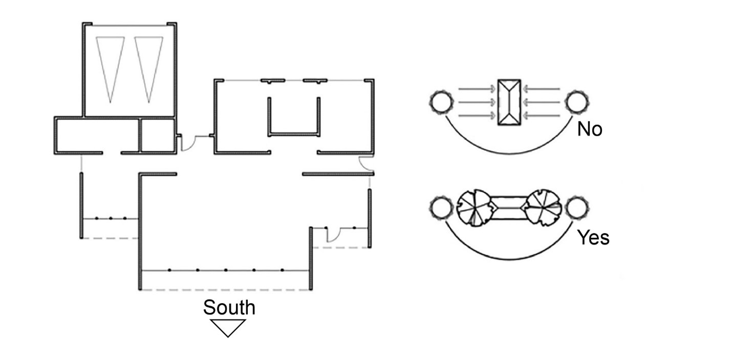
Right: This house plan orients broad building surfaces away from the west and east, trees are used to shade the west and east, and large overhangs shade windows on the south wall
Image
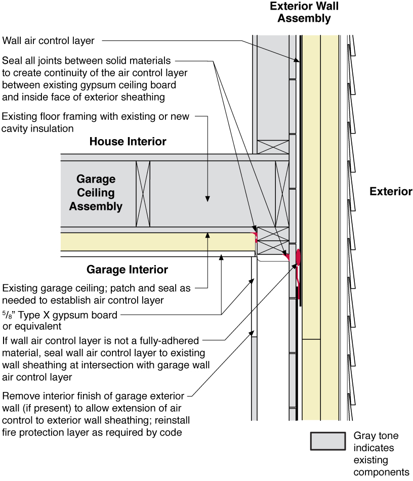
Rigid foam insulating sheathing installed over an existing garage ceiling with retrofits to air seal exterior wall before adding exterior wall insulating sheathing
Image
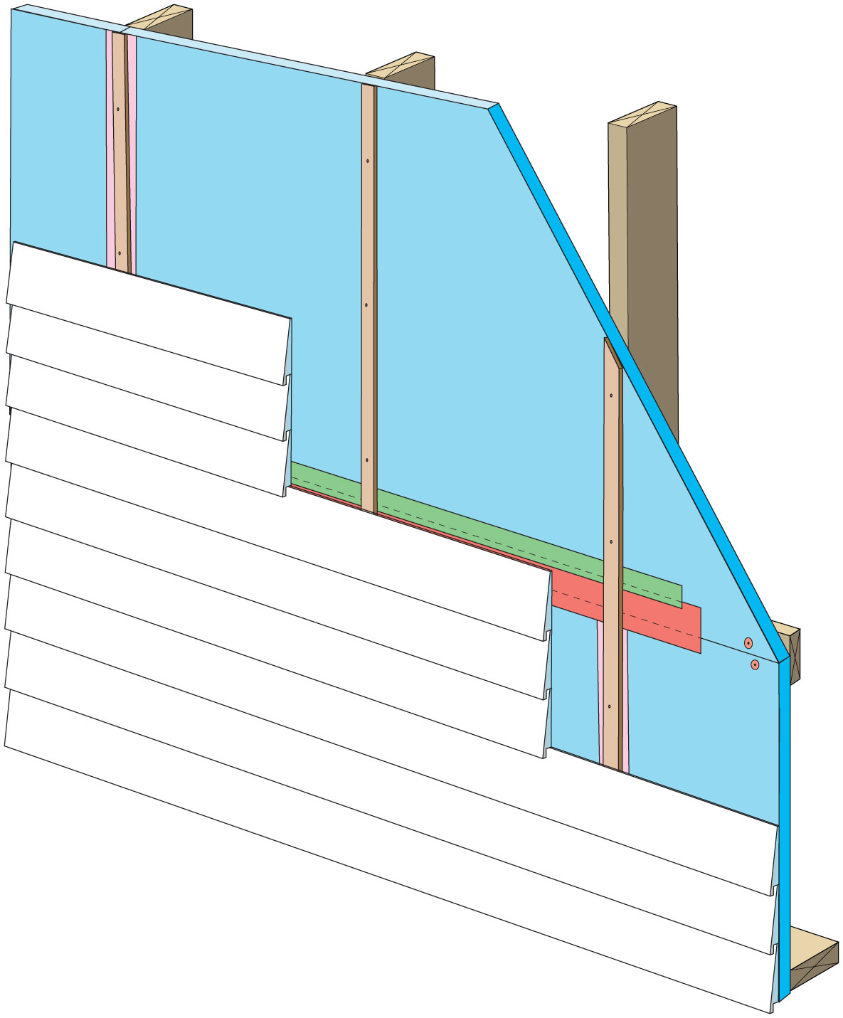
Rigid foam insulation can serve as the drainage plane when all seams are taped. Furring strips provide an air gap behind the cladding.
Image
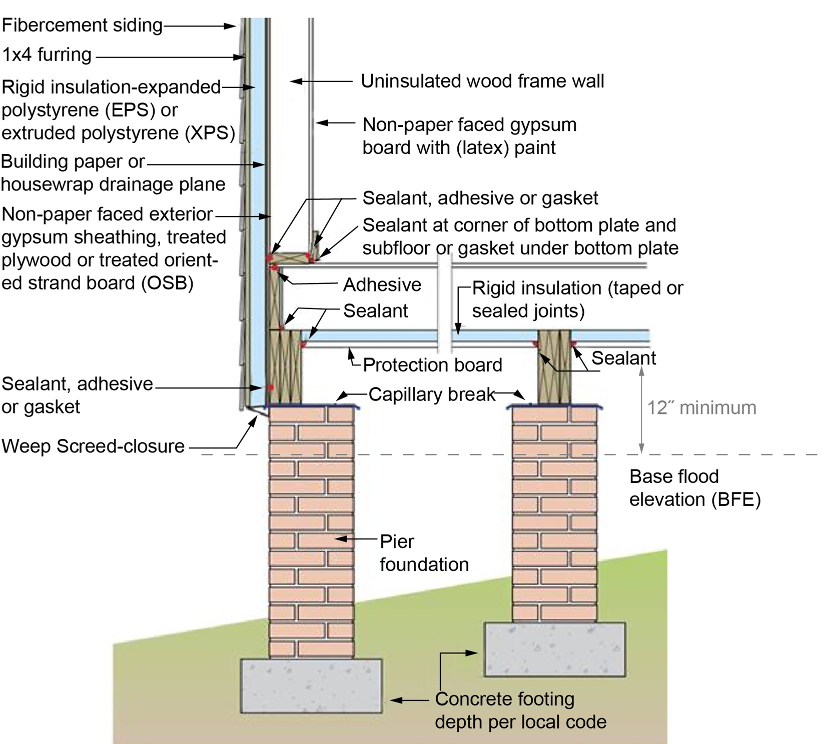
Rigid foam provides the code-required insulation values for this floor and wall assembly so that fibrous cavity insulation can be avoided, reducing risk of floodwater damage
Image

Image
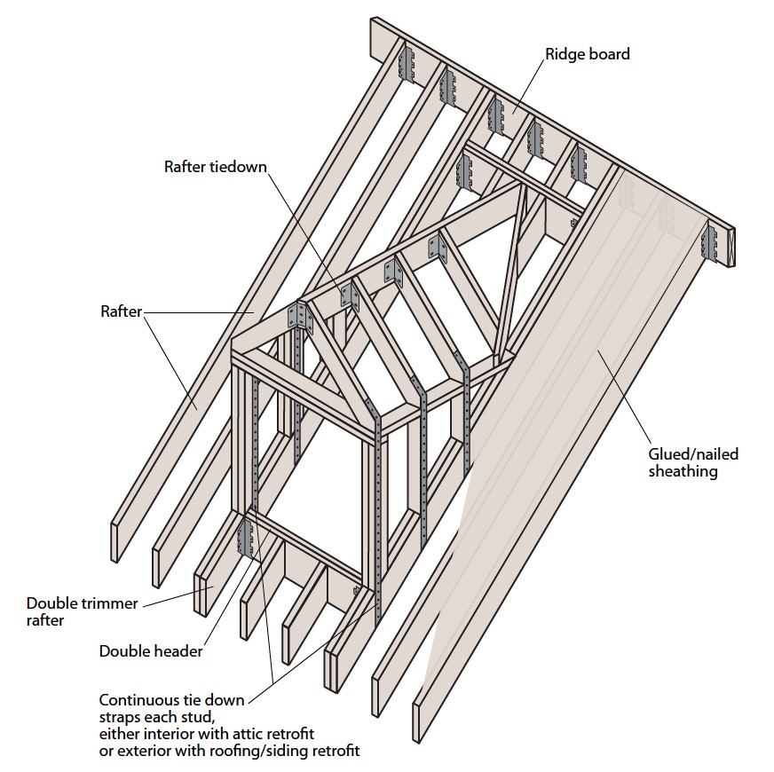
Roof dormer is braced with steel connectors and strapping to increase its resistance to uplift
Image
Image
Image
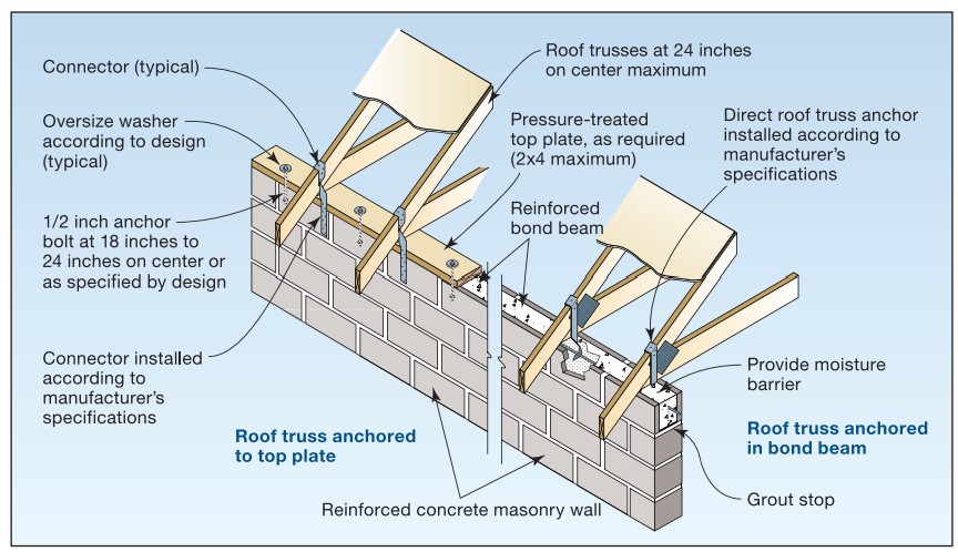
Roof truss-to-masonry wall connectors embedded into concrete-filled or grouted masonry cell (left-hand side image has a top plate installed while the right-hand side does not).
Image
Image
Image
Image
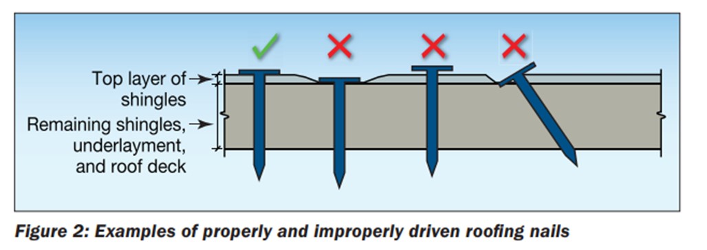
Roofing nails should be driven in straight and flush, not overdriven, underdriven, or angled
Image
Image
Image
Image

Image
Image
Image

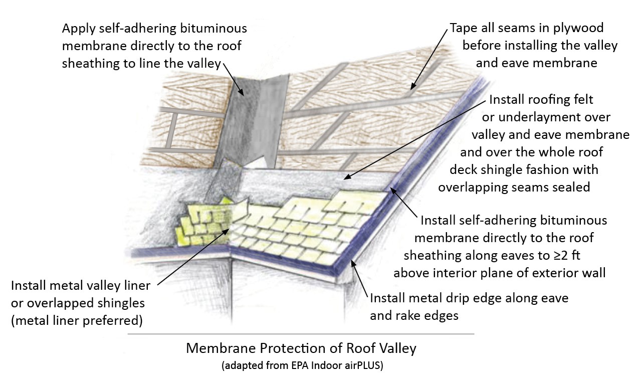
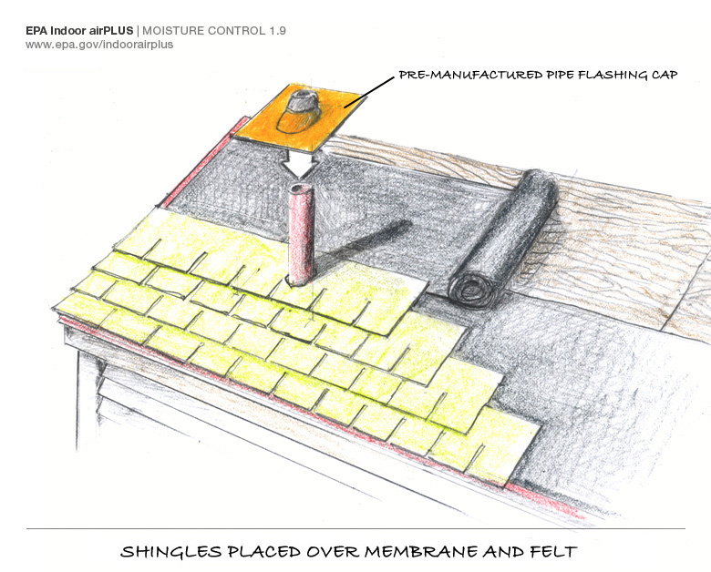
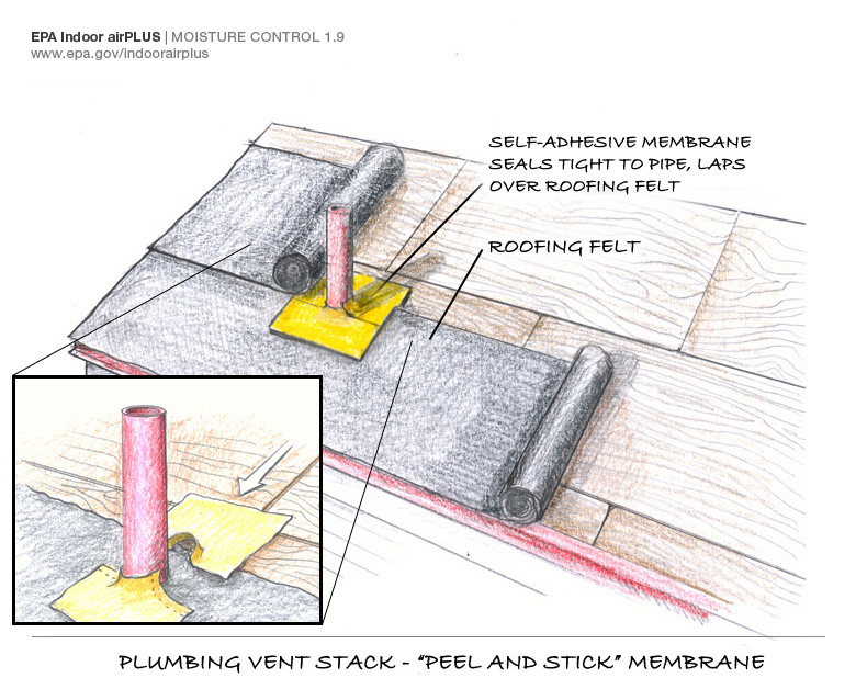
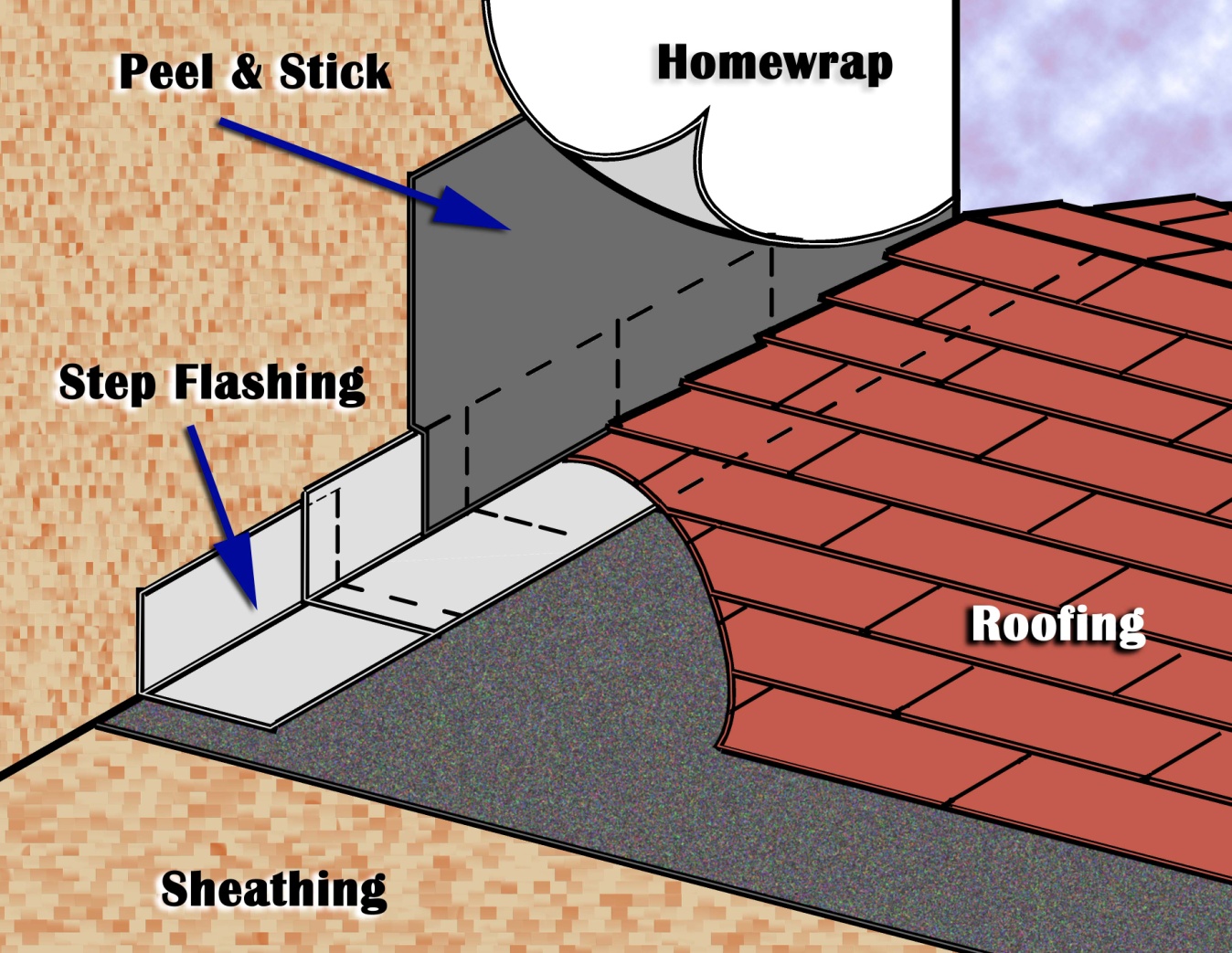
Seal the roof deck as follows: Sweep roof decking, tape seams, and cover underlayment or roofing felt as shown.
Image
Image
Image
Image
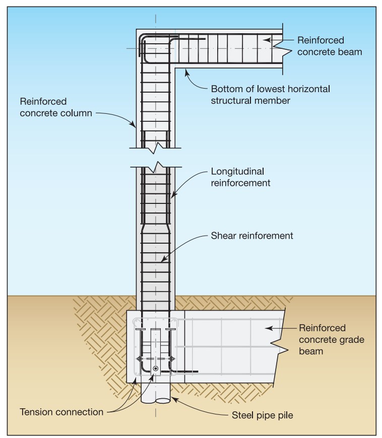
Section view of a deep pile foundation system constructed with reinforced concrete beams and columns to create portal frames, adapted from FEMA P-550, 2nd ed., case FEMA P-550, 2nd ed., case H.
Image
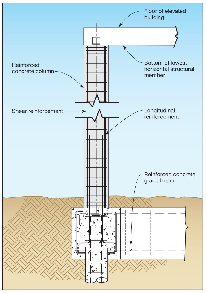
Section view of a steel pipe pile with concrete column and grade beam foundation type, adapted from FEMA P-550, case B.