Showing results 1 - 198 of 198
Image
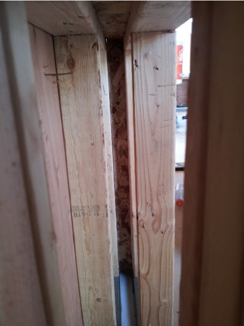
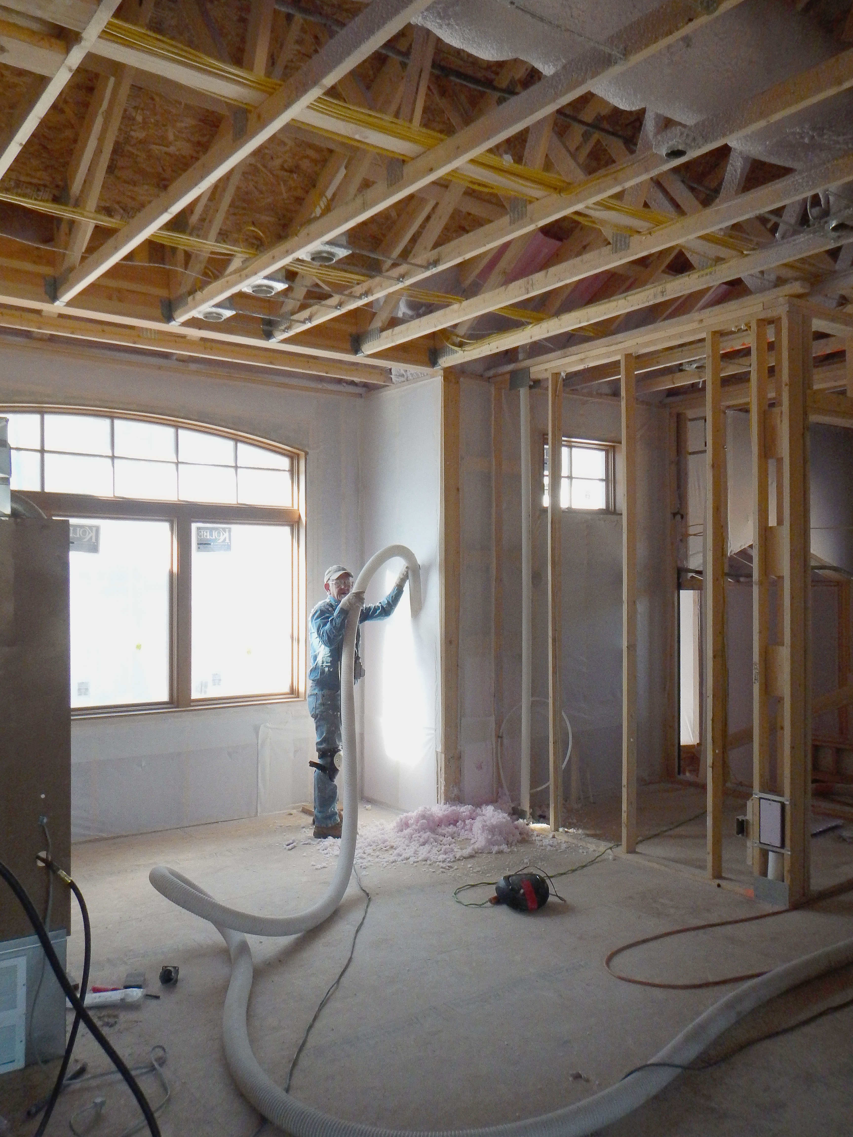
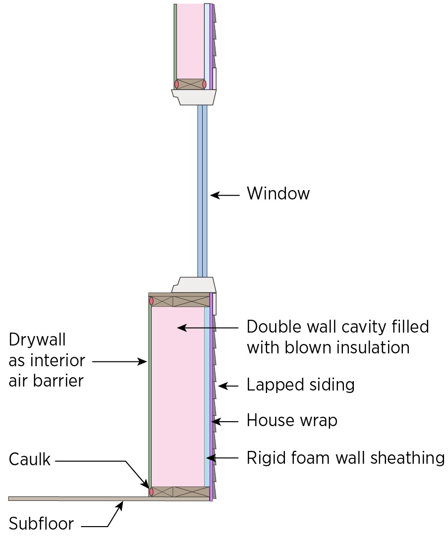
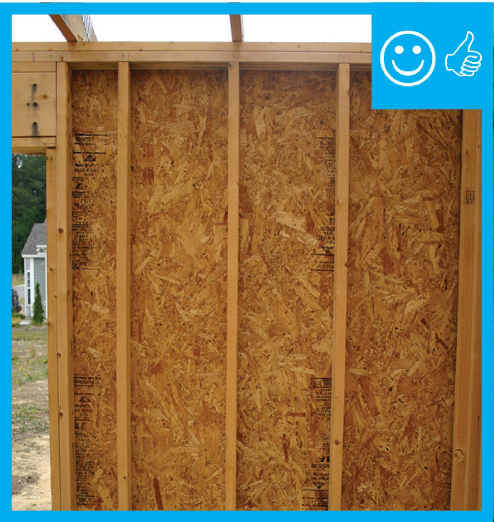
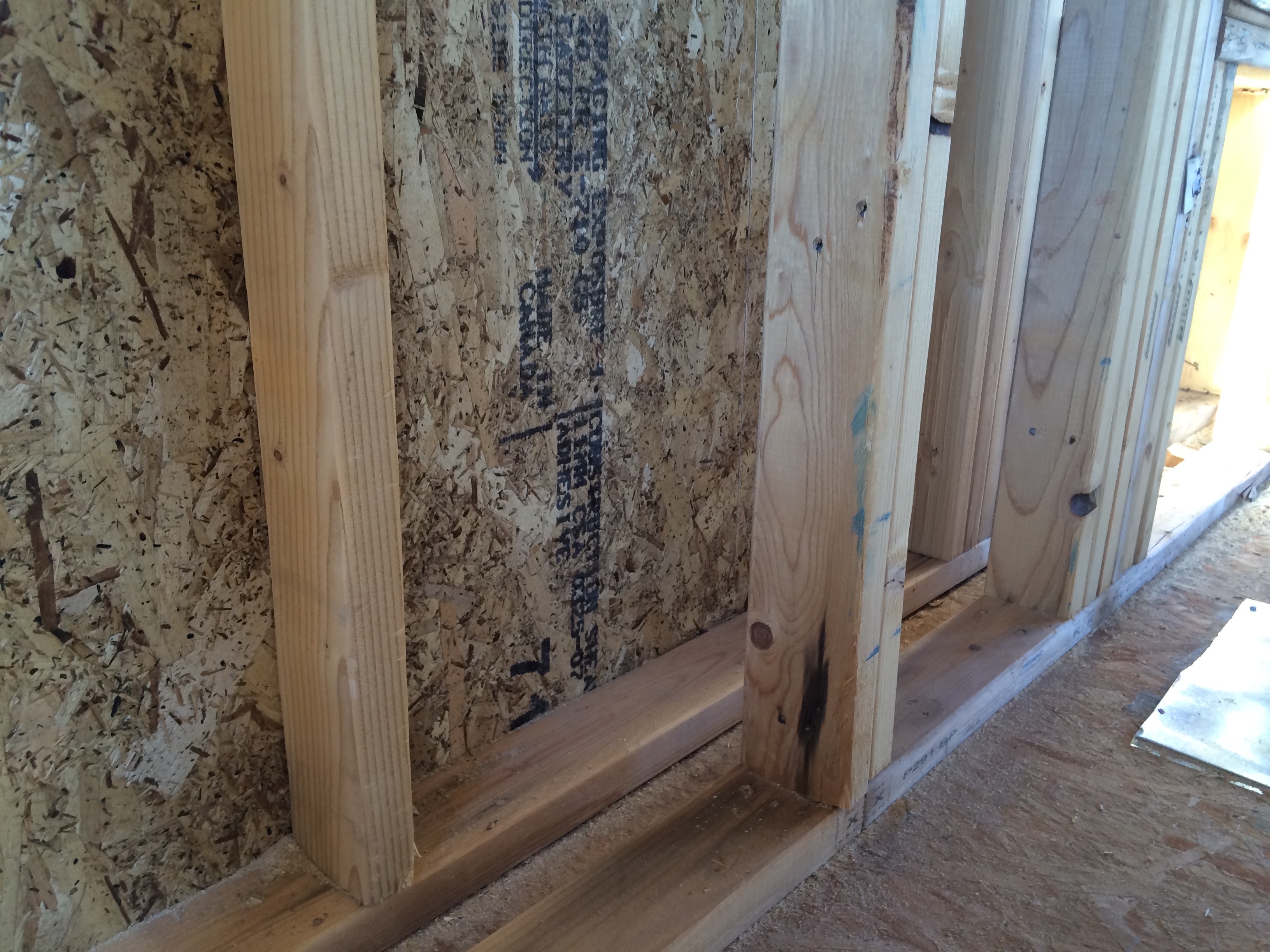
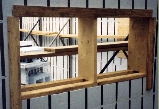
Example of the advanced framing technique, double-stud wall cavity, which will later be filled with blown insulation
Image
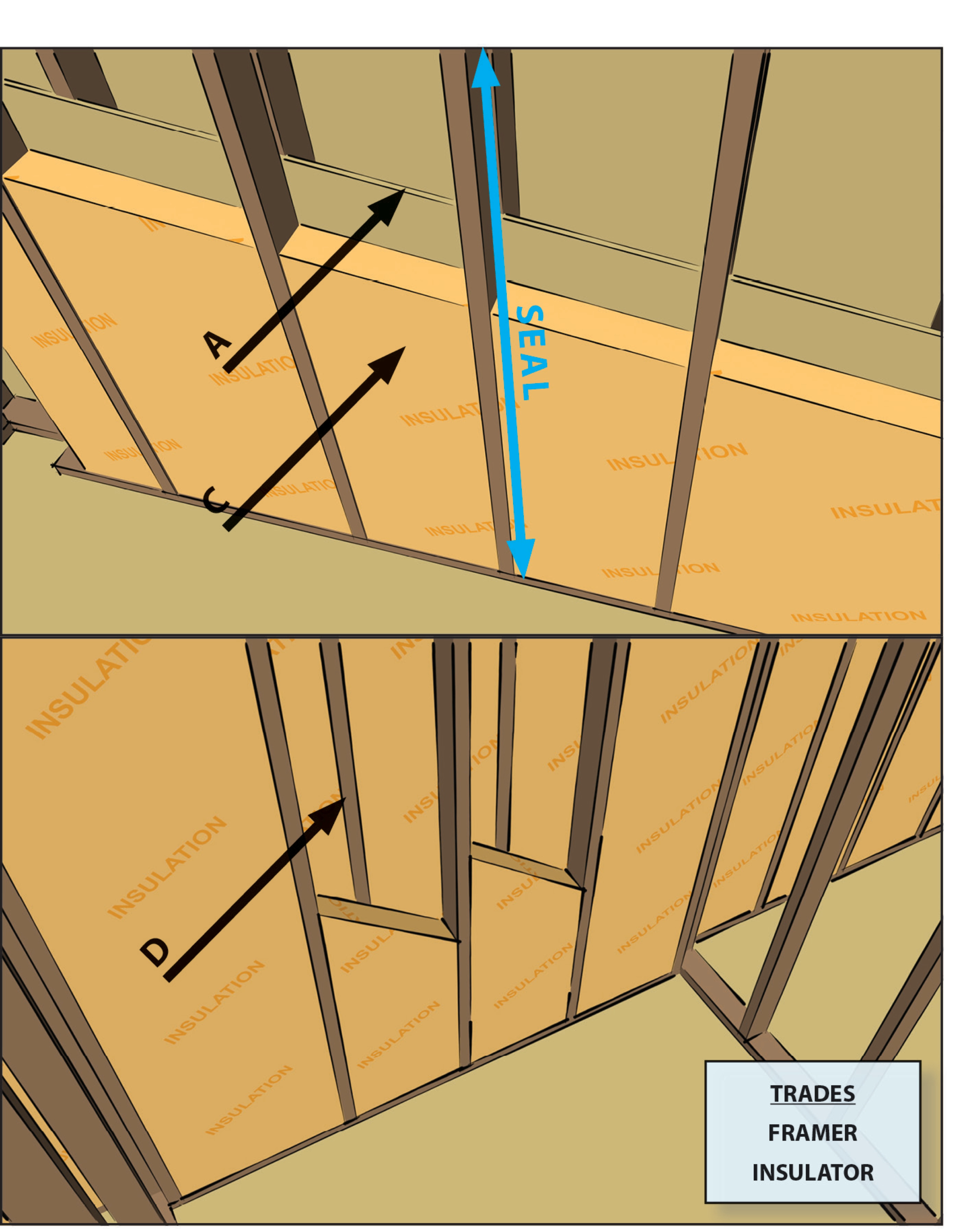
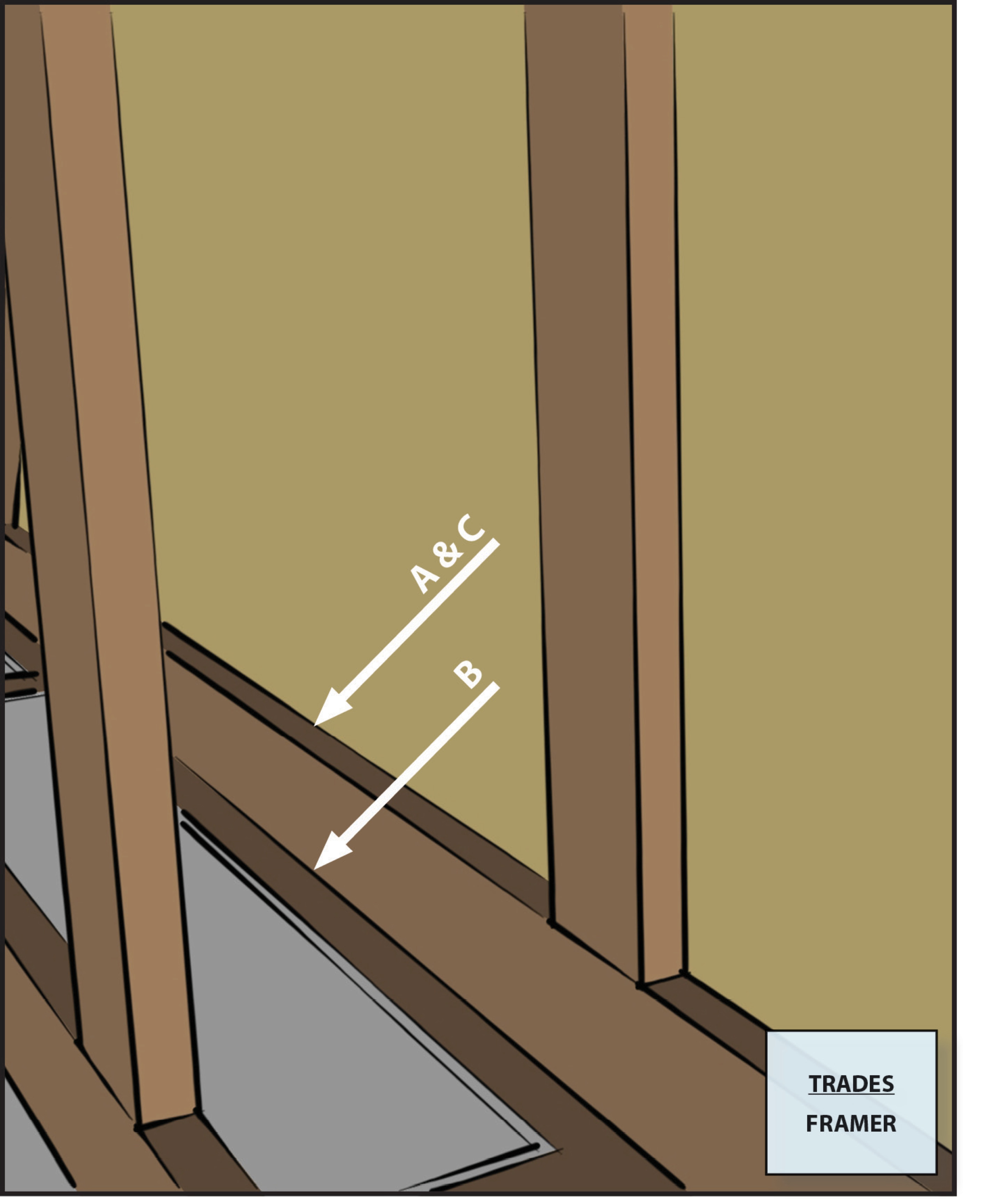
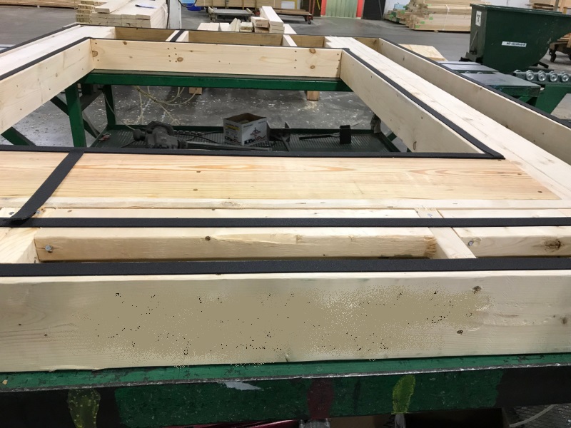
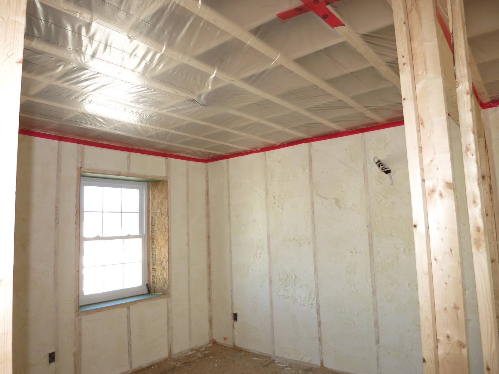
A large bead of caulk is installed on the interior surface of the wall top and bottom plates to provide an air sealing gasket between the framing and the dry wall.
Image
Image
Image
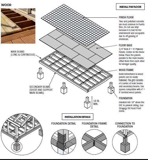
A raised wood pier foundation can raise the subfloor above the design flood elevation.
Image
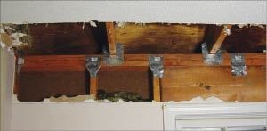
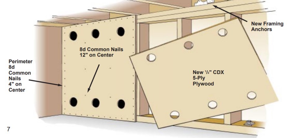
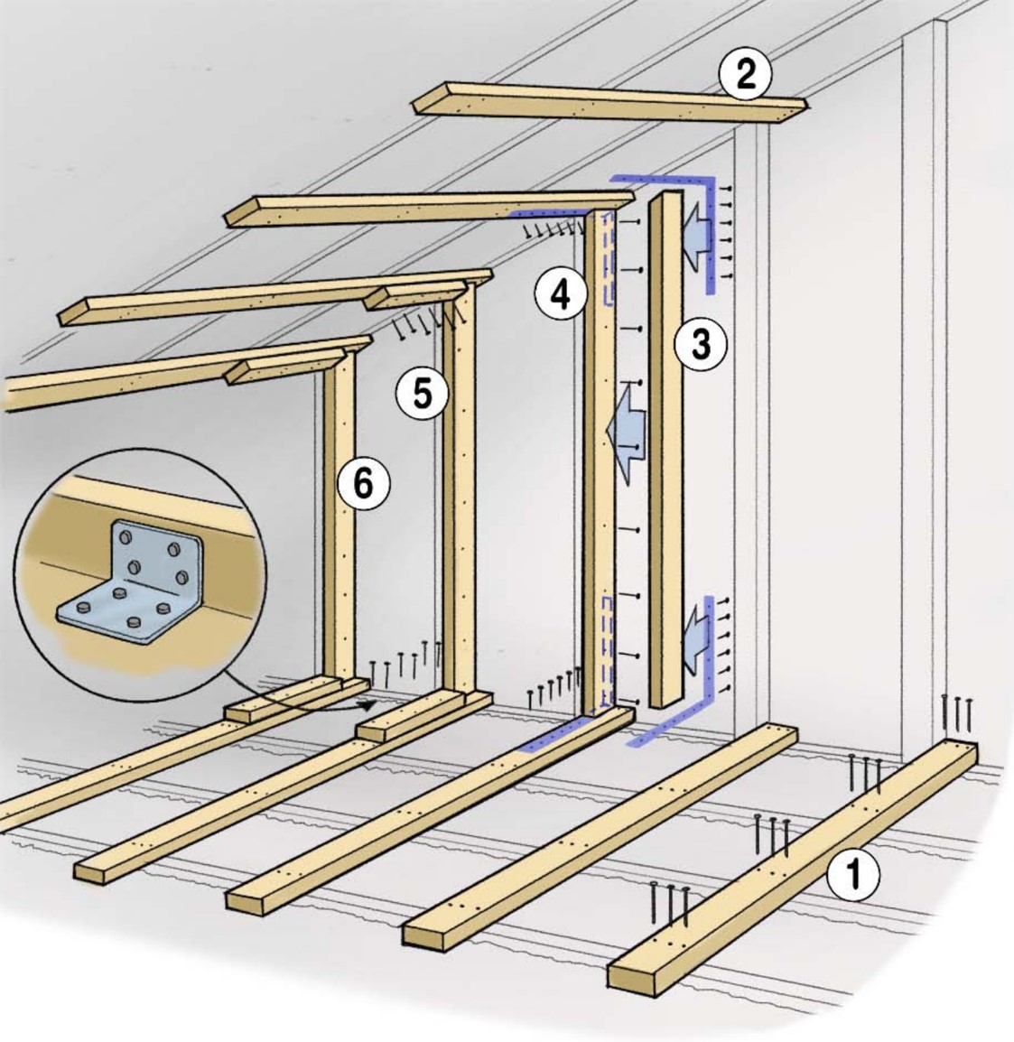
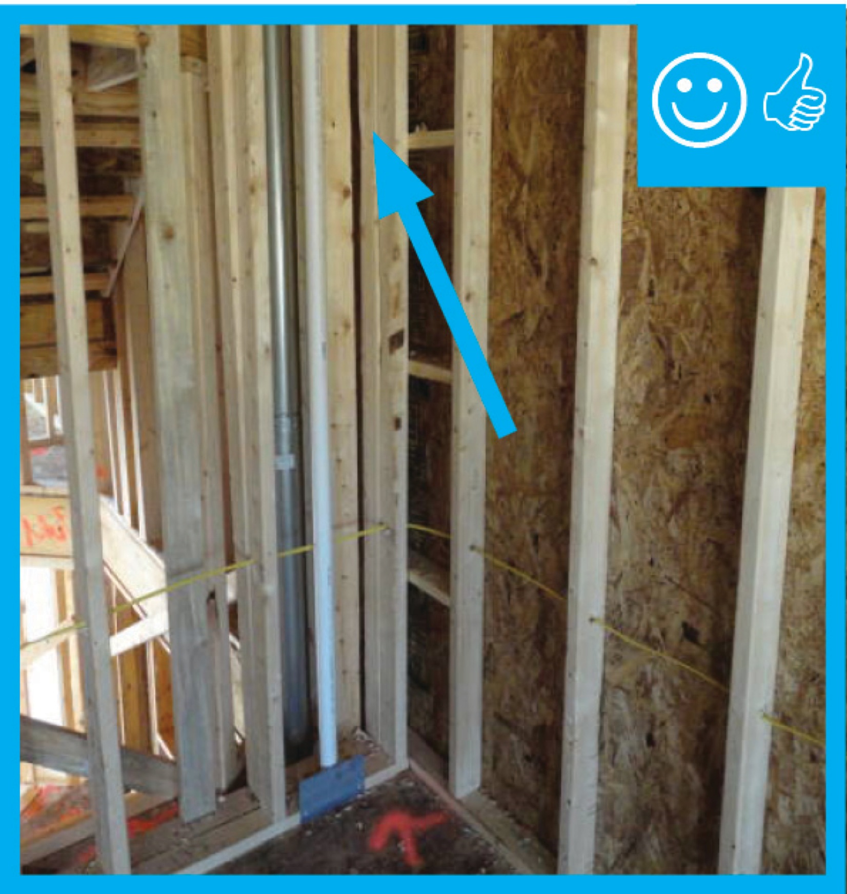
Add metal connectors to strengthen framing connections in an existing wall from inside the home by removing drywall.
Image
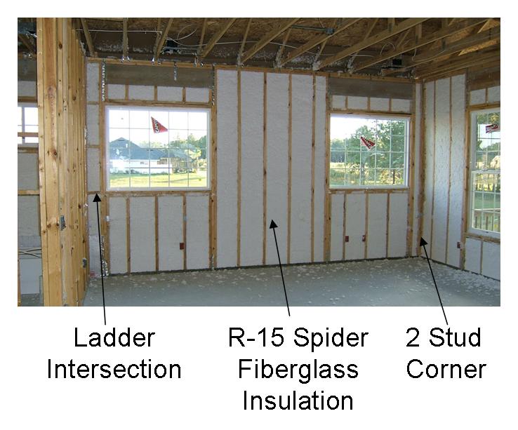
Advanced framing details include corners that are constructed with fewer studs or studs aligned so that insulation can be installed in the corner.
Image
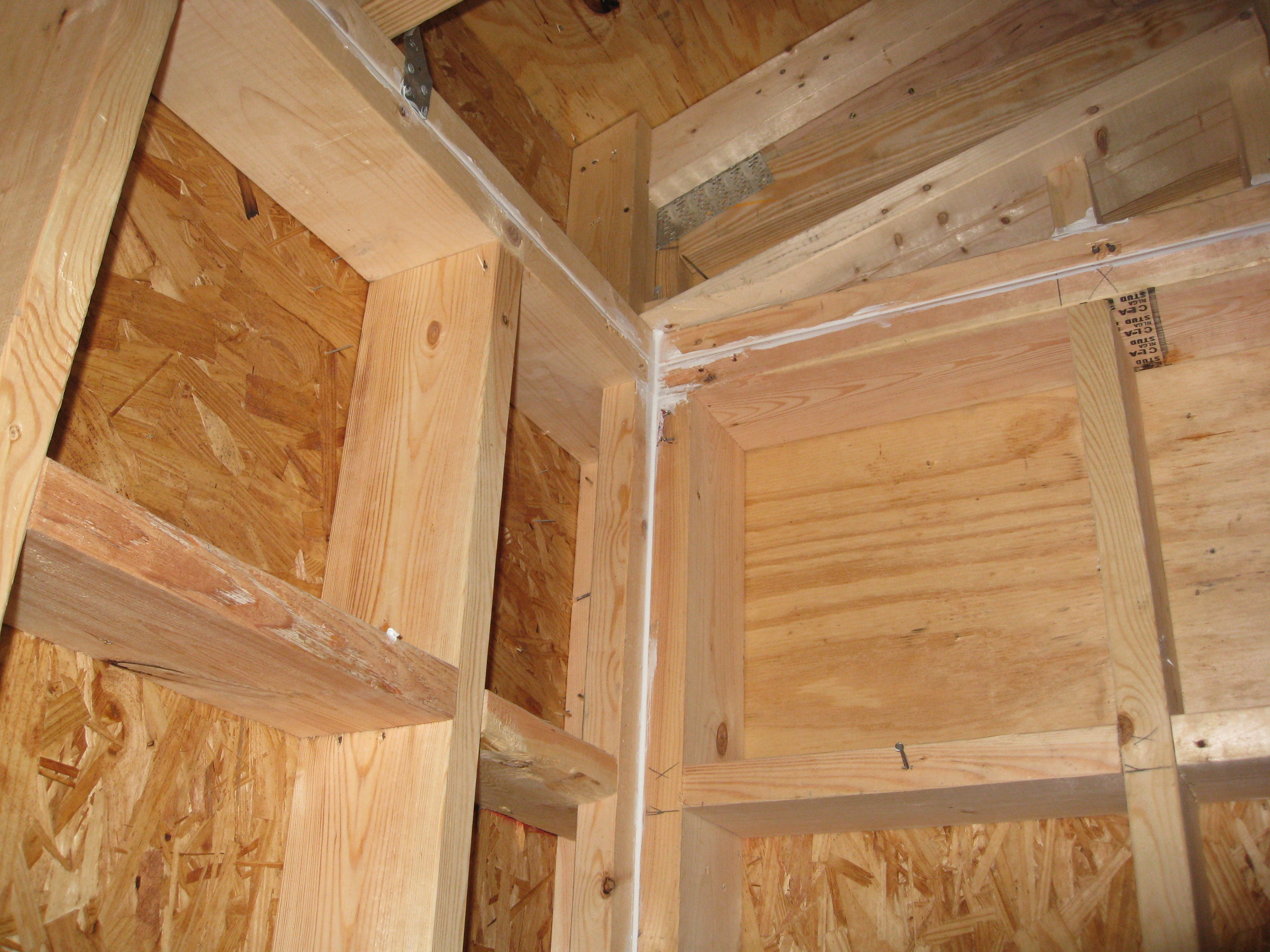
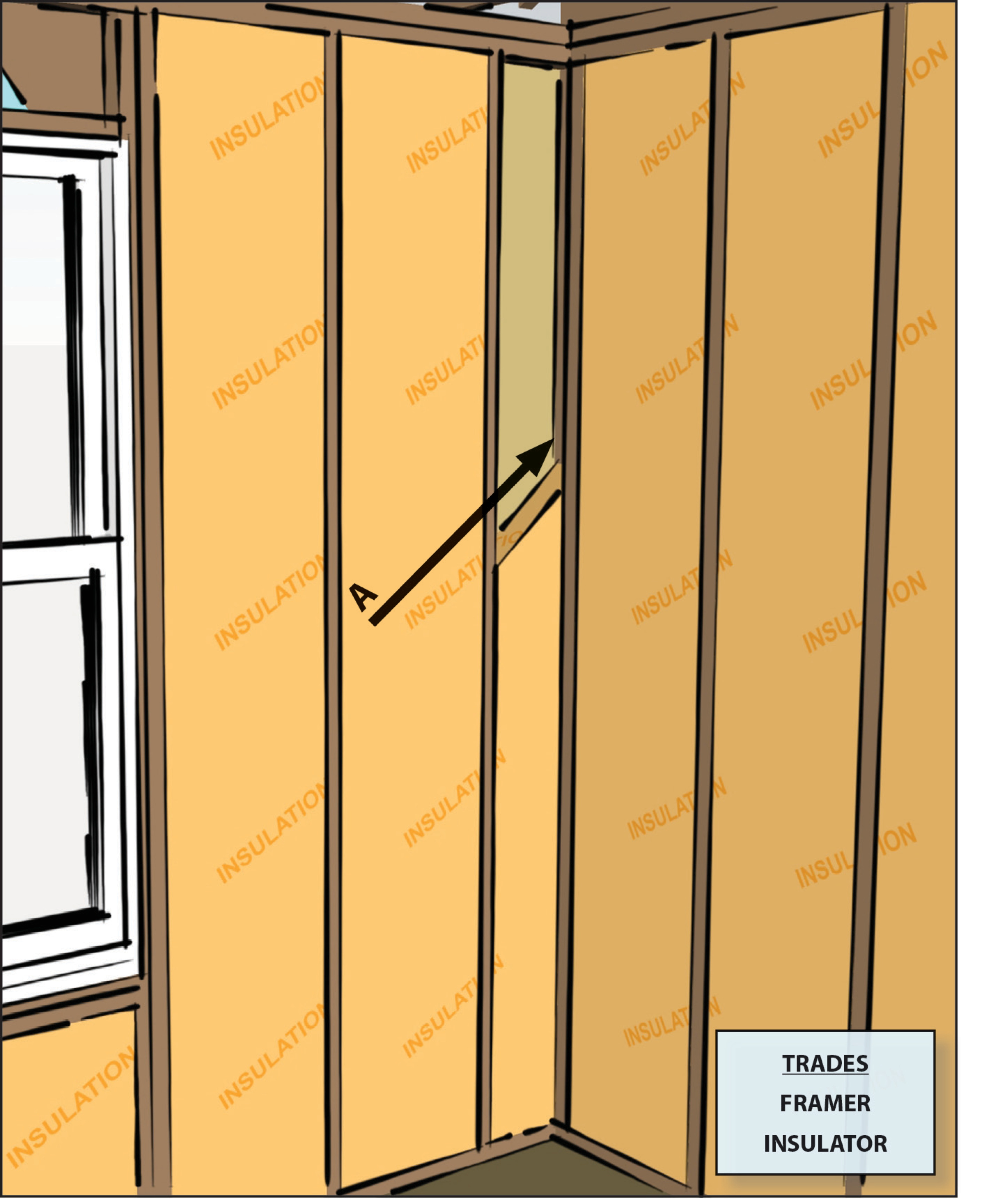
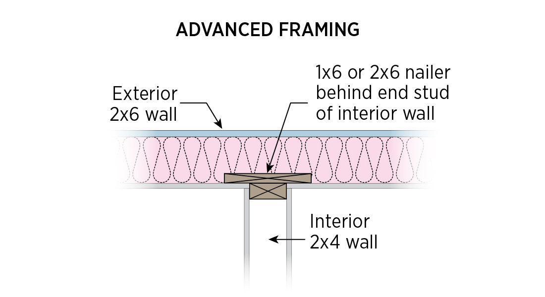
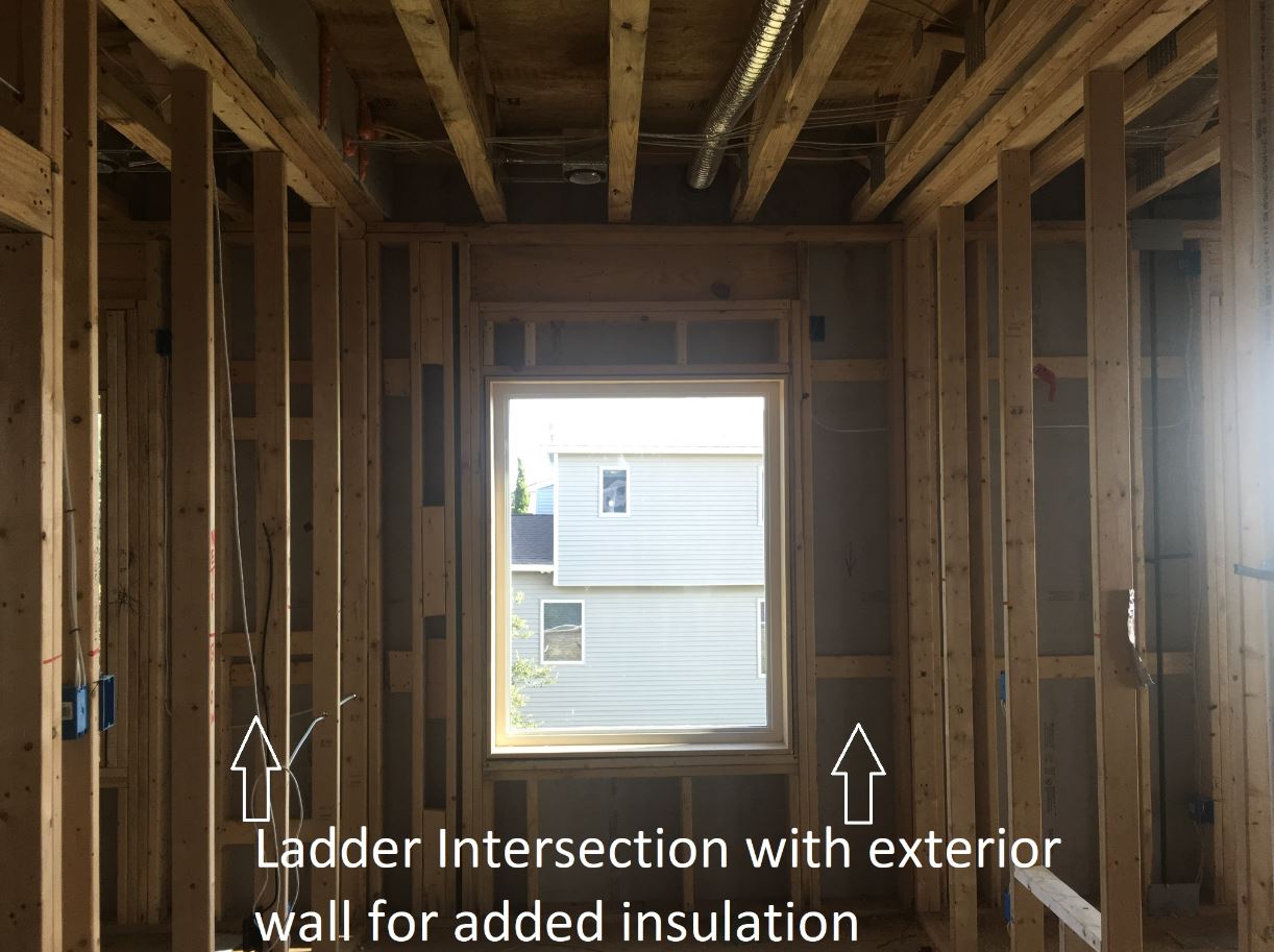
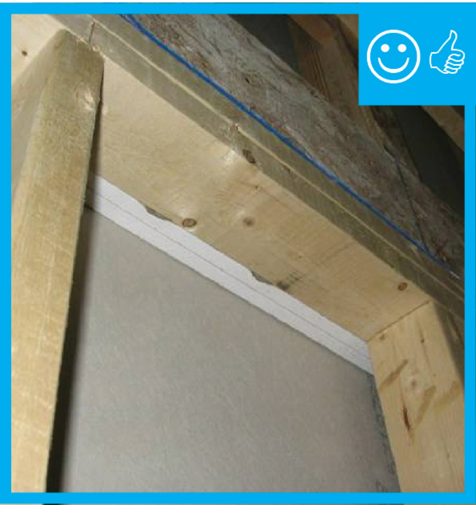
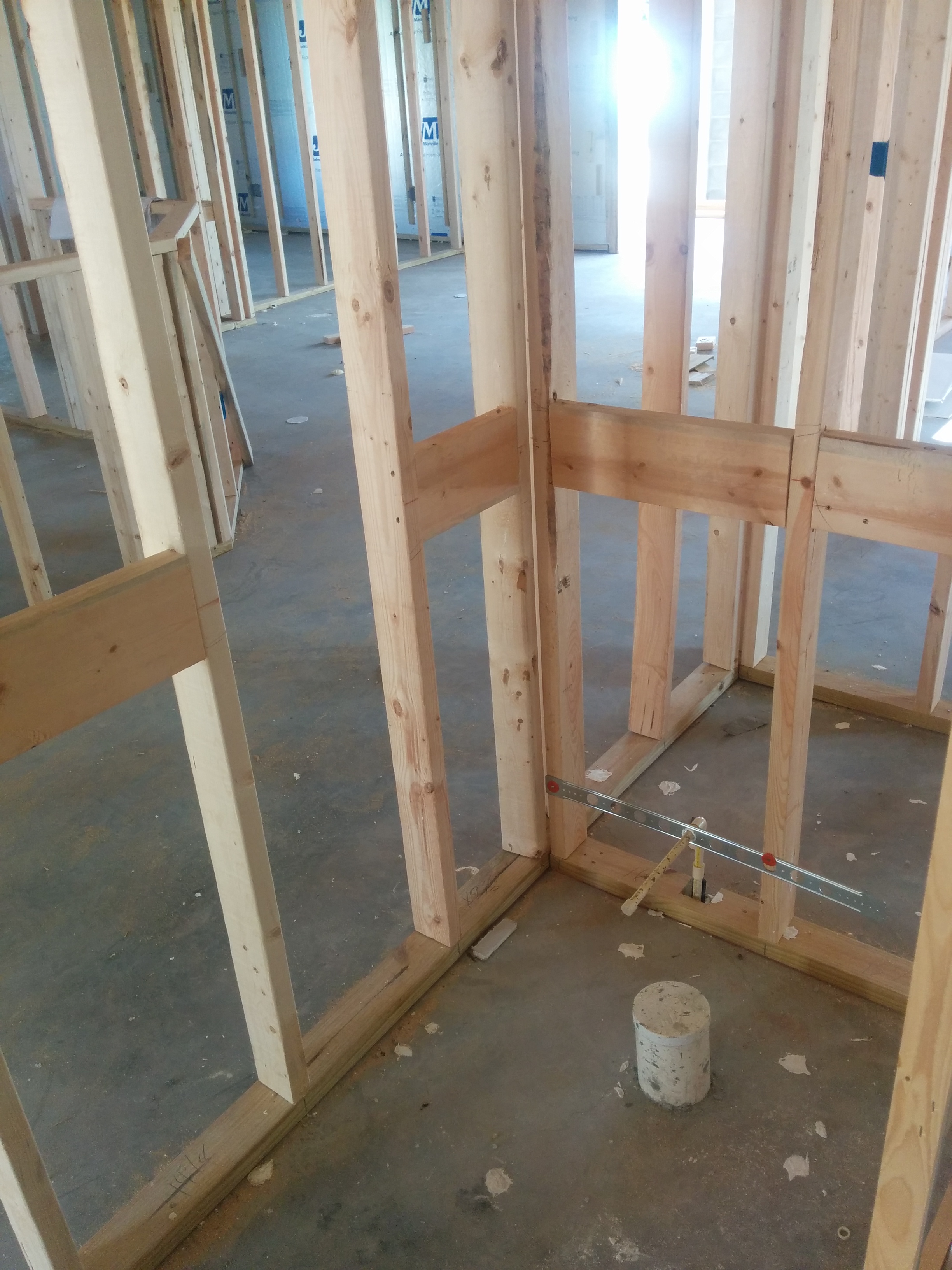
Advanced framing details include framing aligned to allow for insulation at interior-exterior wall intersections.
Image
Image
Image
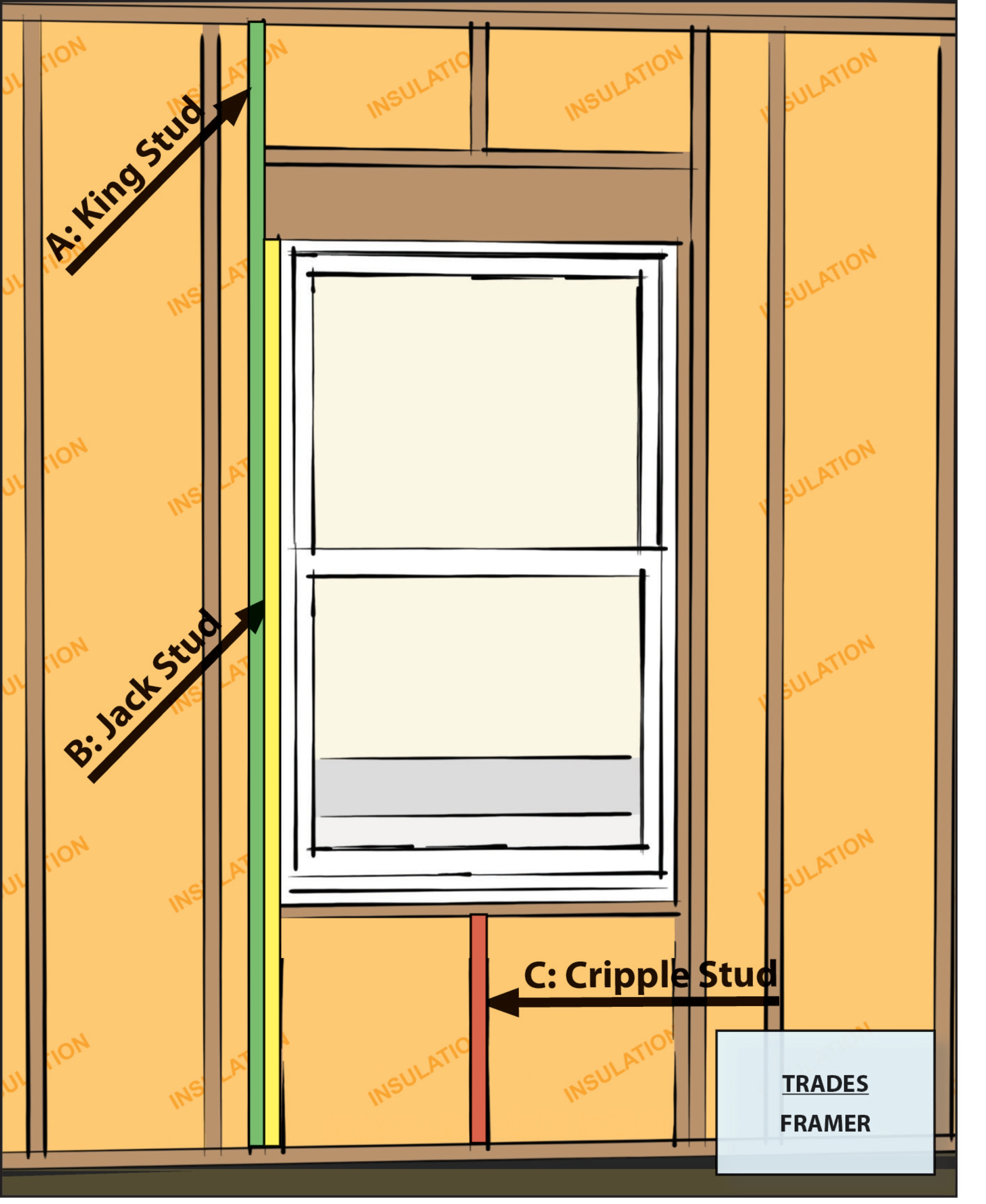
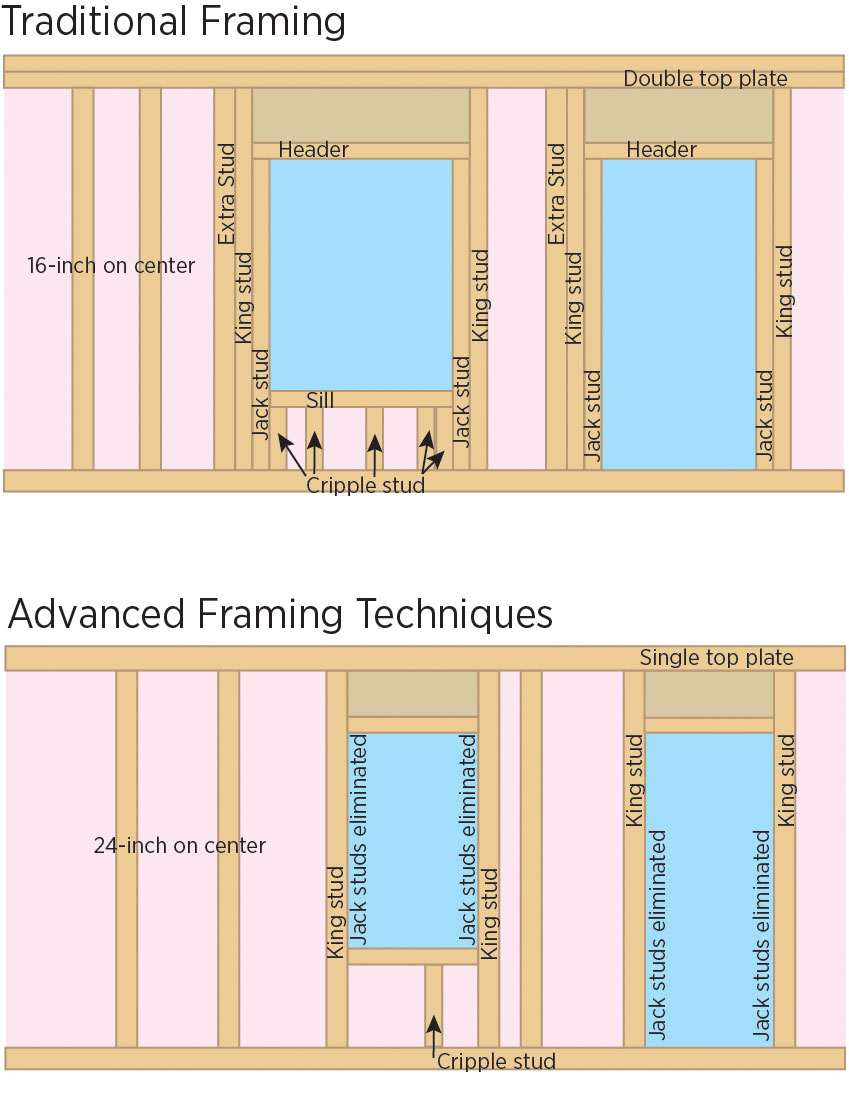
Advanced framing details include open headers and reduced framing around windows and two-stud corners to allow more room for insulation in the wall cavities while reducing lumber costs.
Image
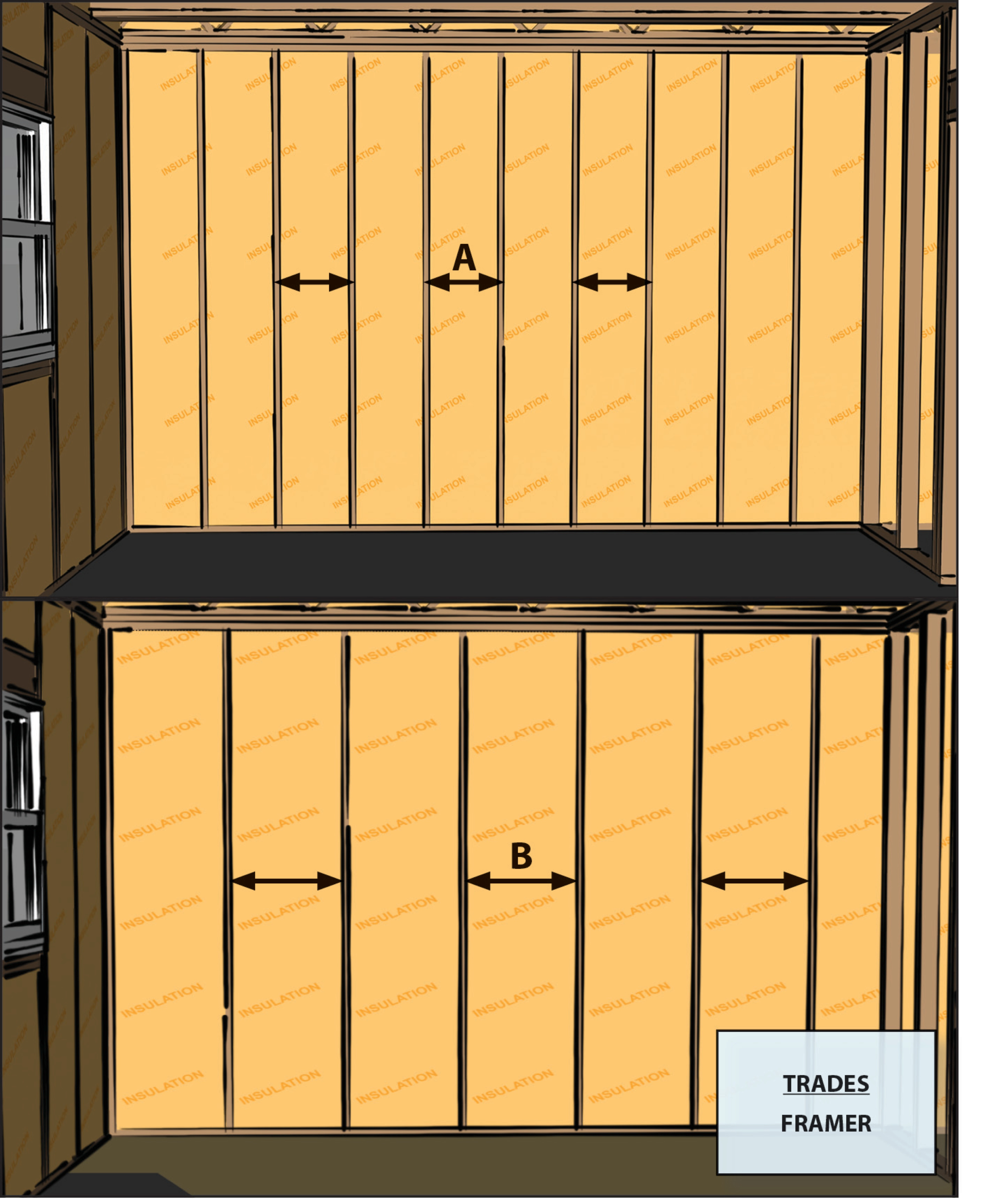
Advanced framing details include using the minimum amount of wall studs permitted by code.
Image
Advanced framing details throughout house limit use of lumber and makes space for bonus insulation.
Image

Image
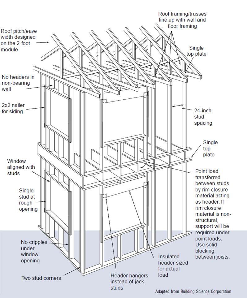
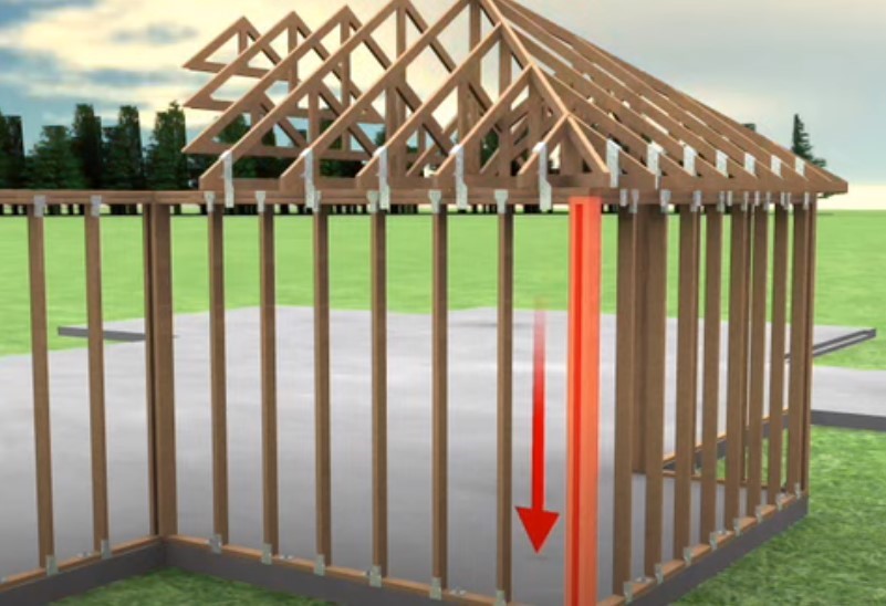
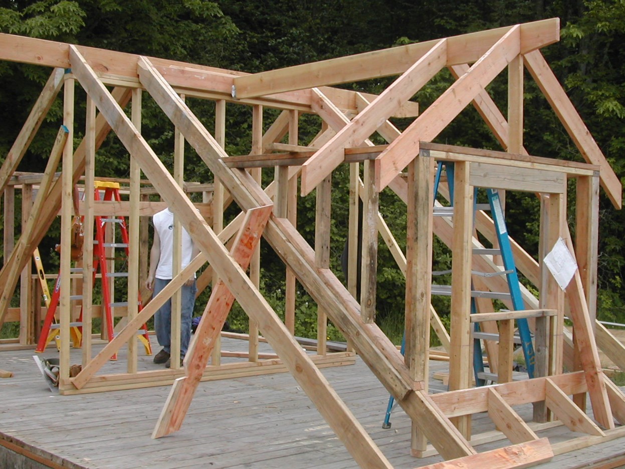
Advanced framing techniques include constructing on a 2-foot grid where wall studs are placed 24 inches on center and aligned with roof and floor trusses for a continuous load path from roof to foundation.
Image
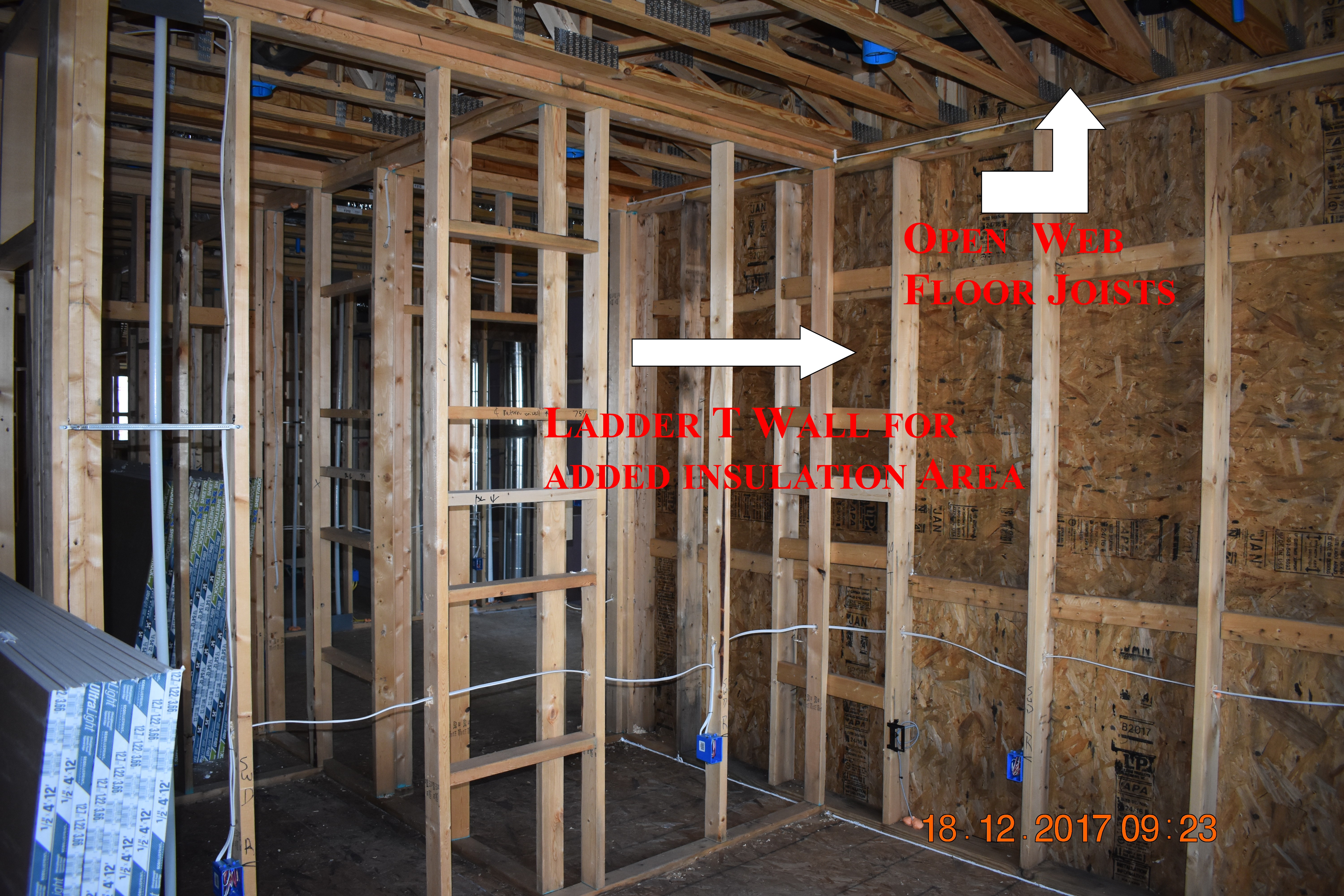
Advanced framing techniques including 2x6 walls spaced at 24 inches on center and ladder blocking at wall intersections allow more space for insulation in the wall cavities while open-web floor joists provide space between floors for ducting.
Image
Image
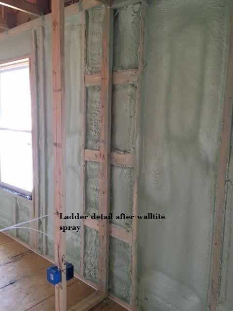
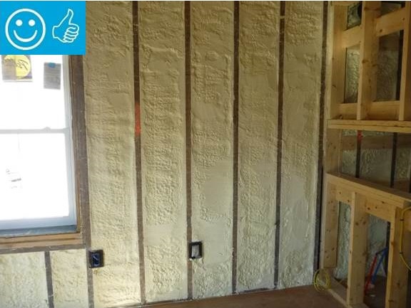
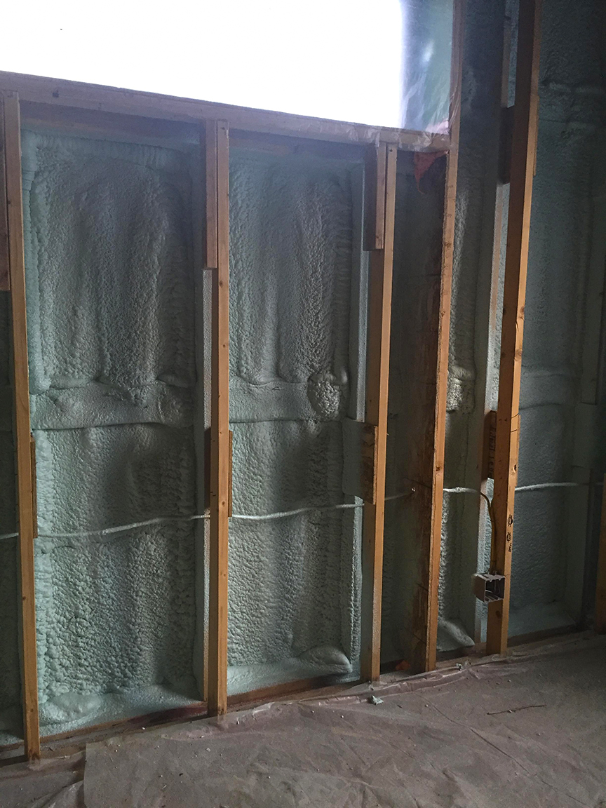
After spraying the 2x6 wall cavities with 2 inches (R-13) of closed-cell spray foam, the walls are covered with netting and an additional 3.5 inches of fiberglass (R-13) is blown in.
Image
Air seal and insulate double-walls that are half-height or full-height walls used as architectural features in homes.
Image
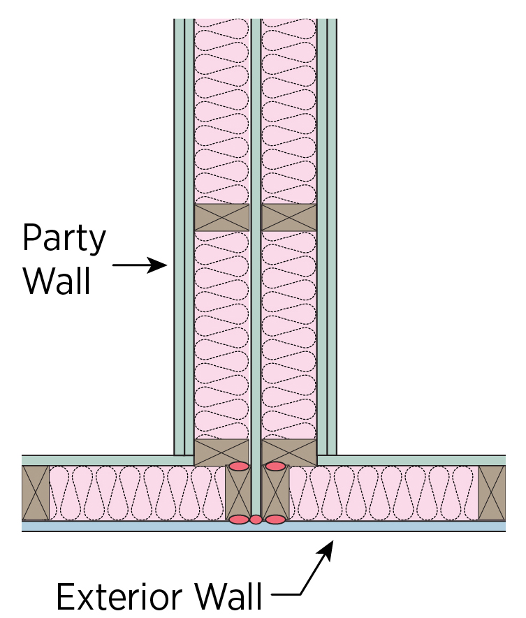
Air seal the common wall between units in a multifamily structure to minimize air leakage.
Image
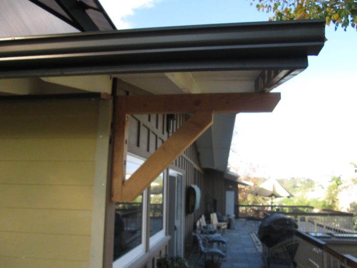
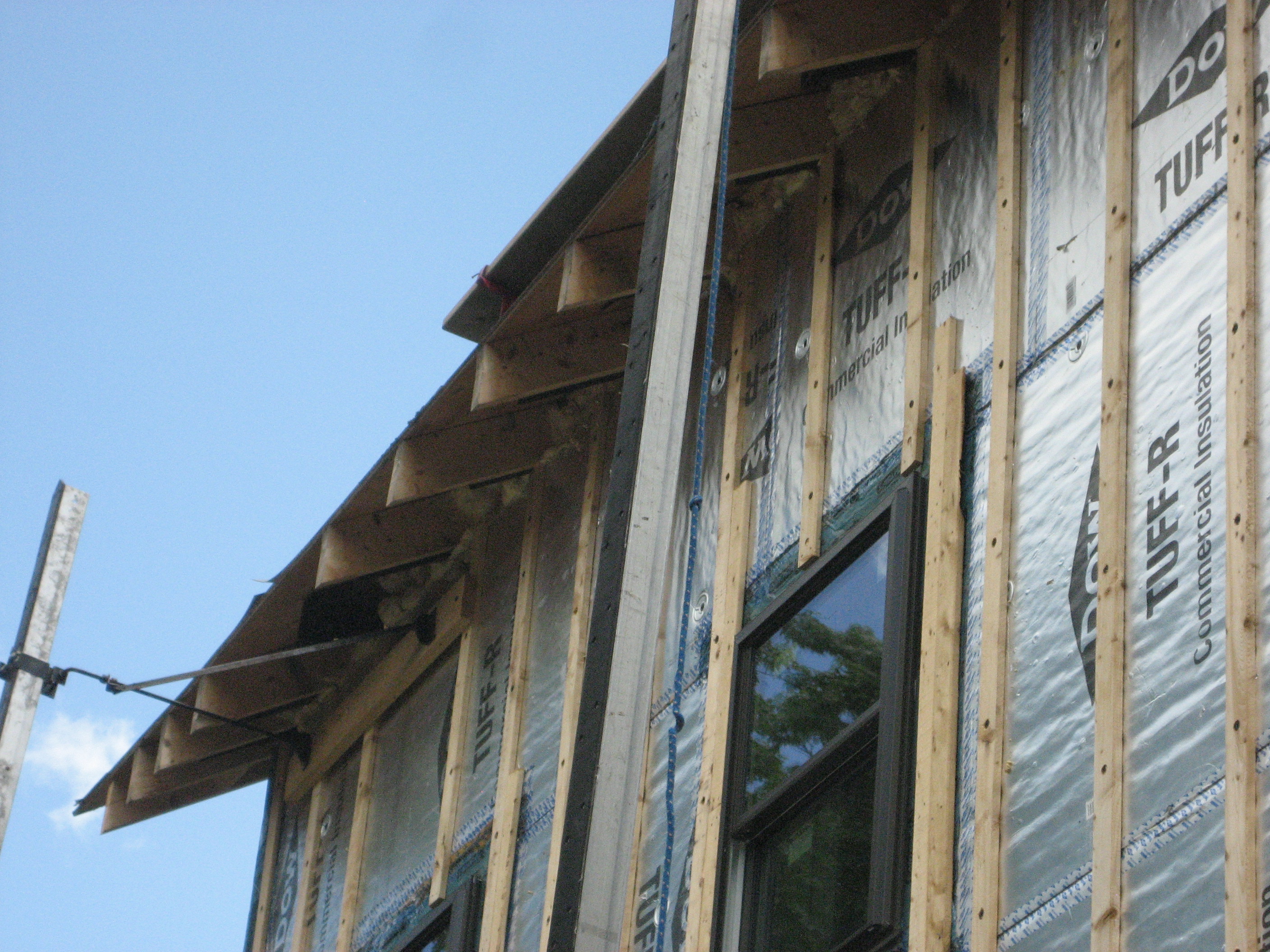
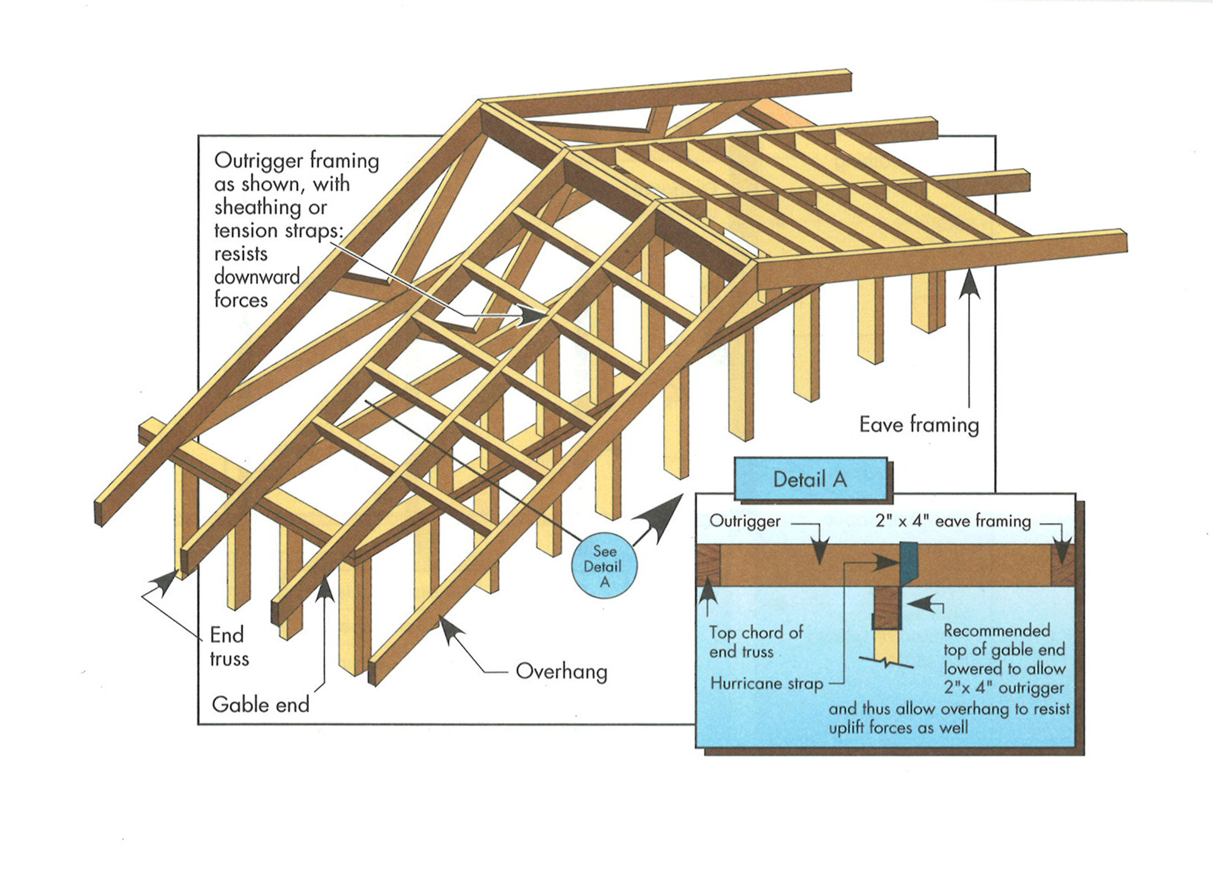
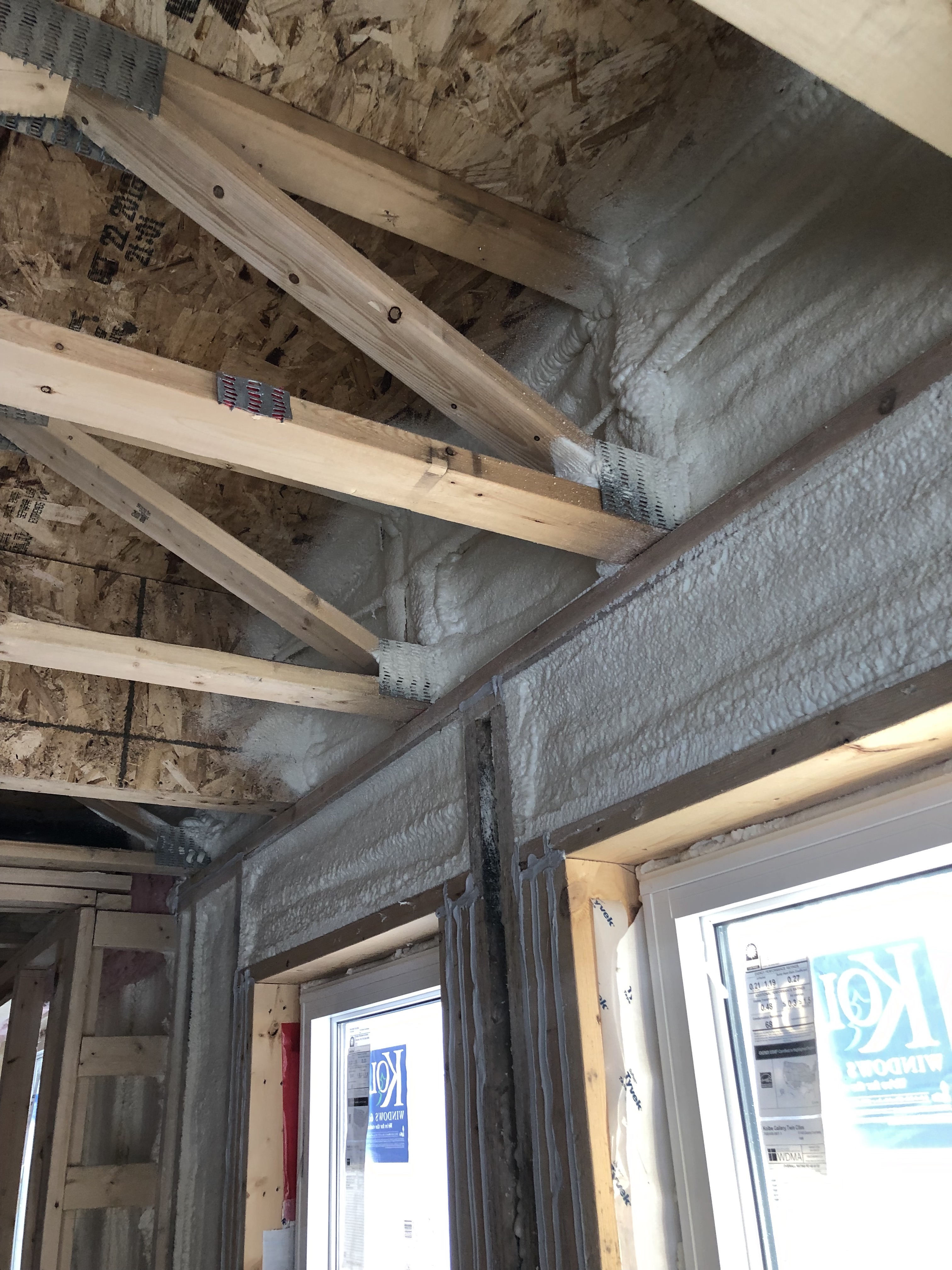
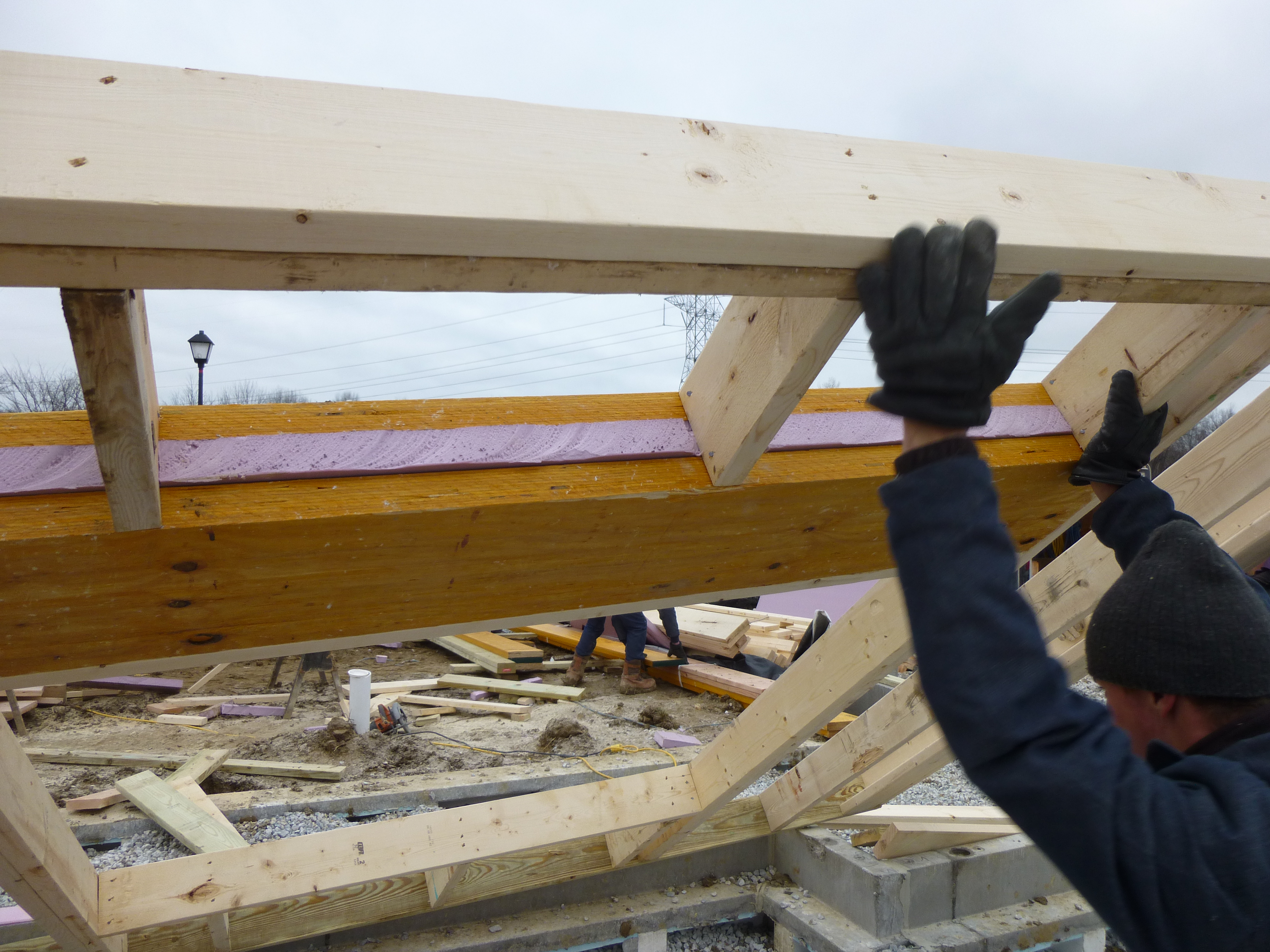
Angle support framing is added to brace a long gable overhang constructed using the ladder framing method.
Image
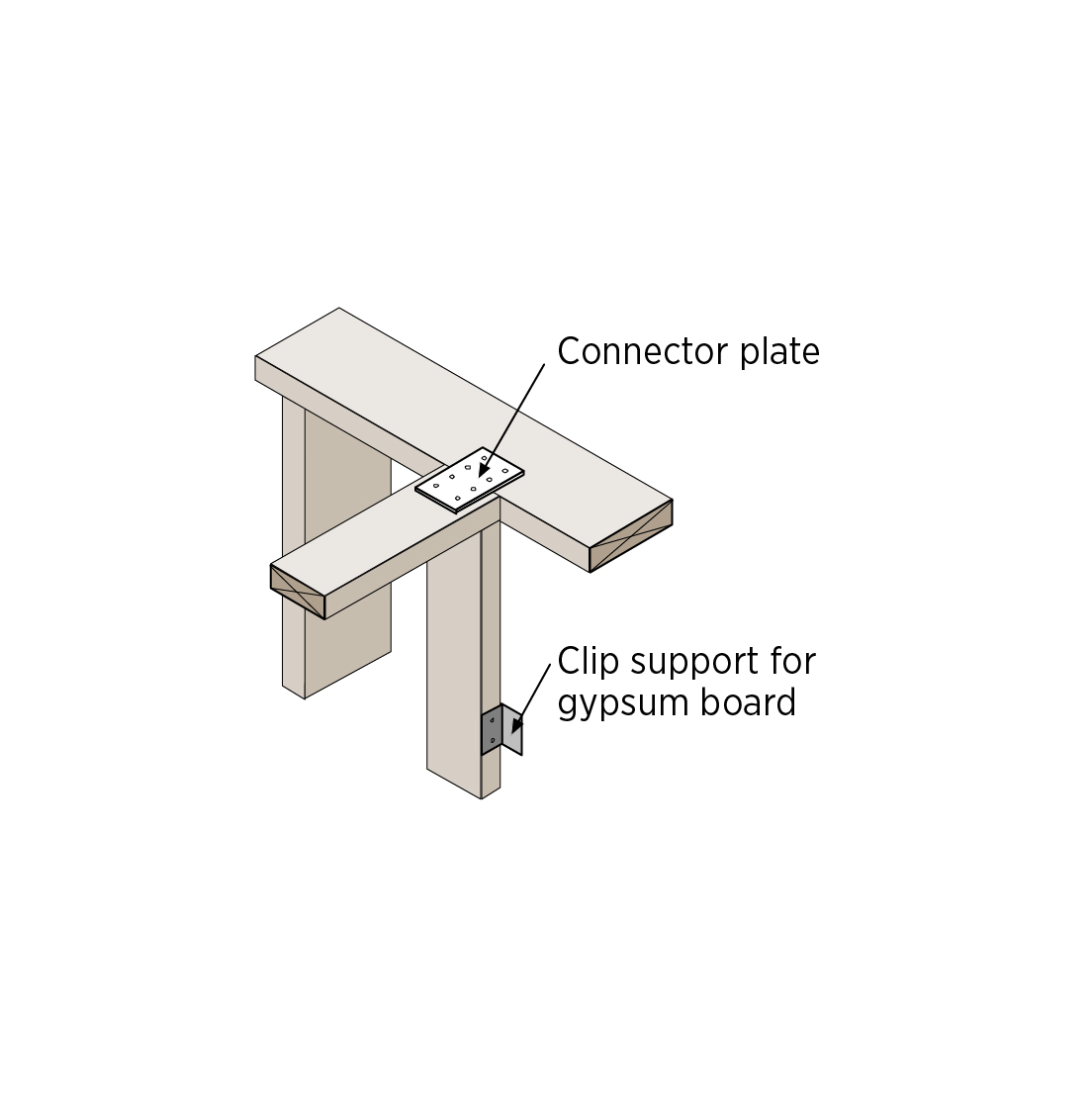
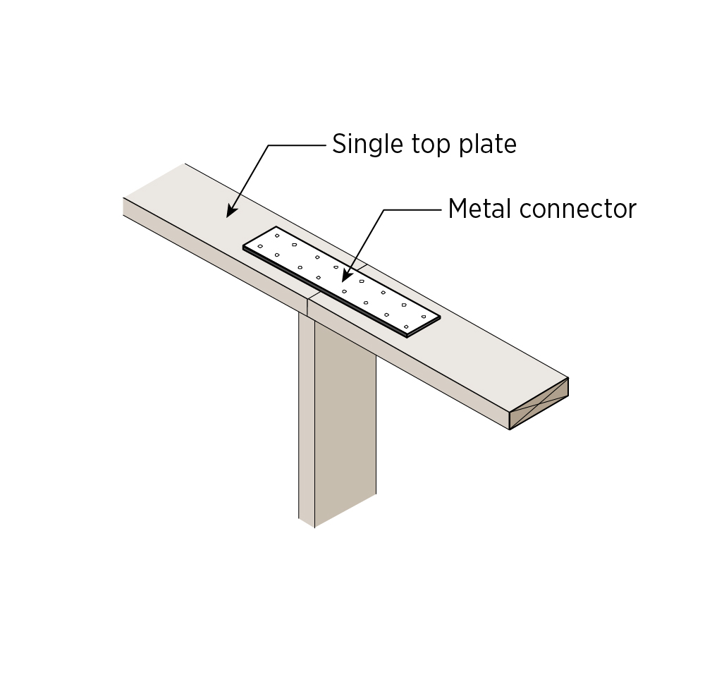
Attach the interior 2x4 wall to the exterior wall top plate with a flat metal connector plate
Image
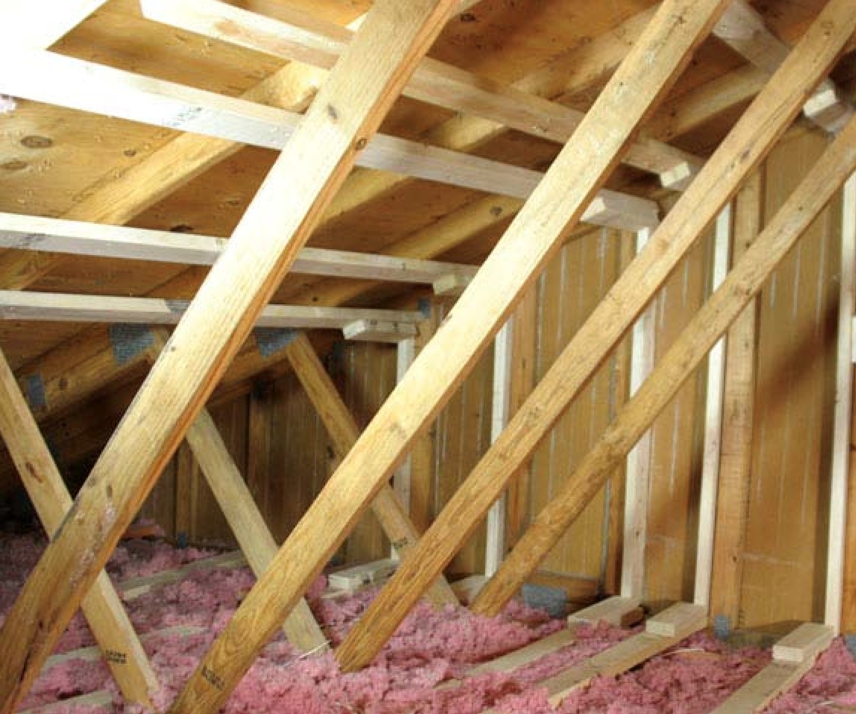
Baffles will keep insulation out of the soffit vents and wind out of the insulation in this vented attic.
Image
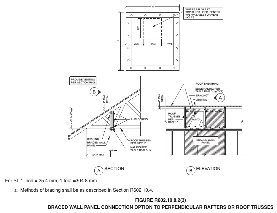
Braced cripple wall construction in crawlspace anchored to framing and foundation
Image
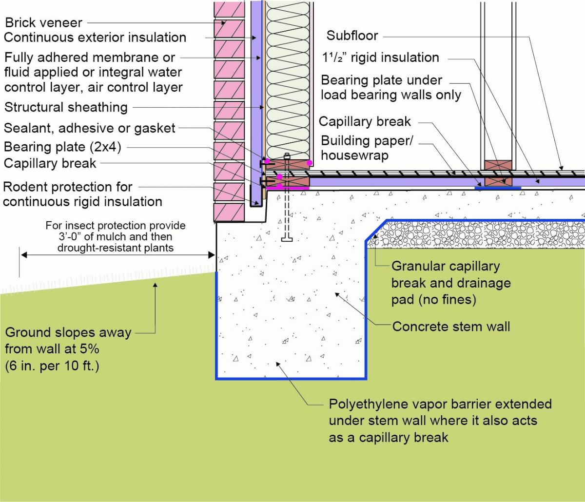
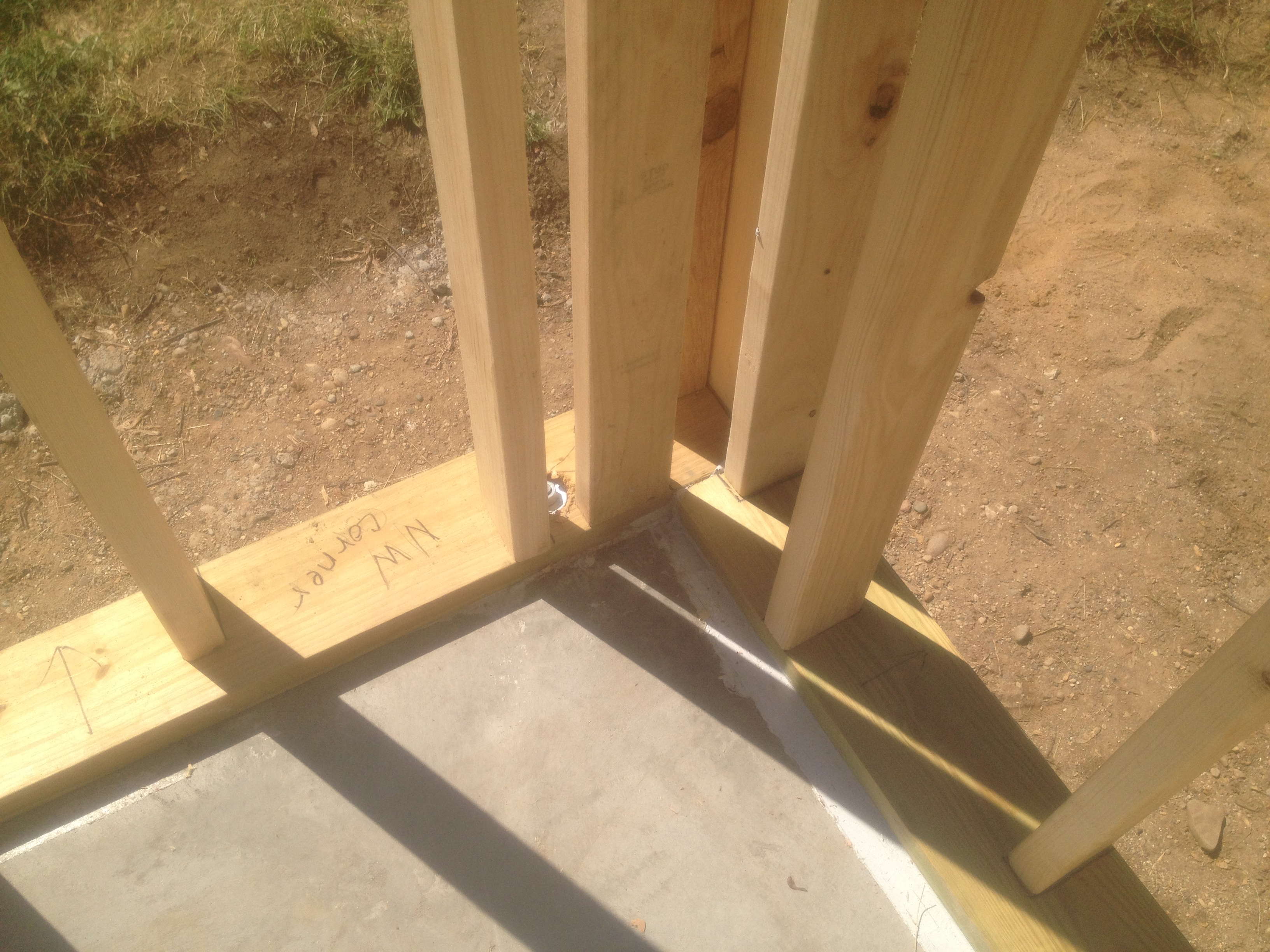
Brick veneer framed wall supported by a concrete slab-on-grade foundation with a turn-down footing insulated on its top surface, showing anchorage of the wall to the foundation for seismic resistance
Image
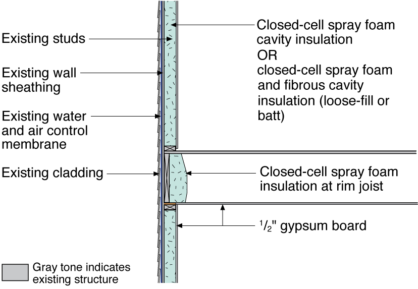
Closed-cell spray foam insulation is added to the wall cavities of an existing exterior wall
Image
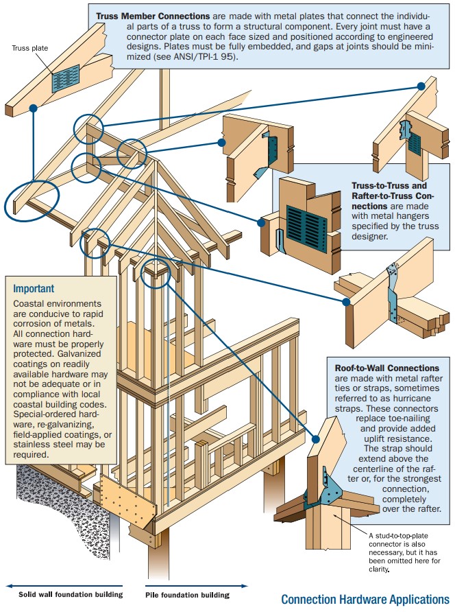
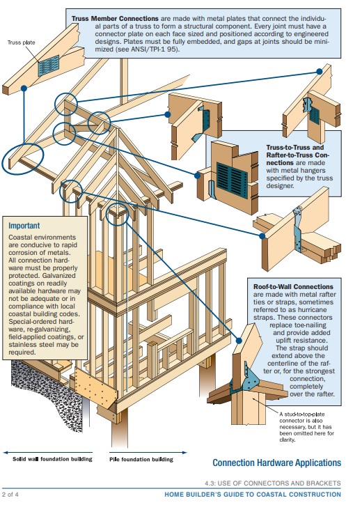
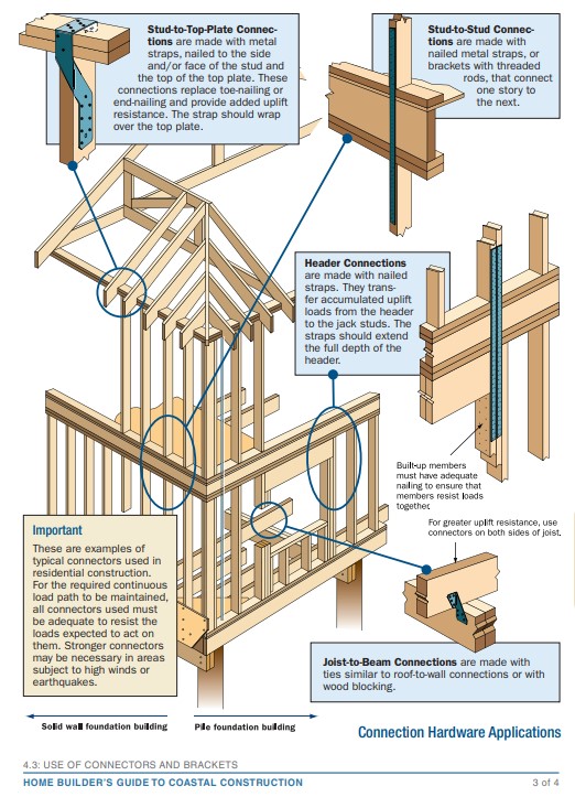
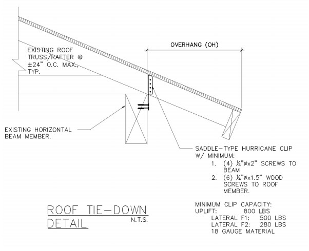
Connecting hardware helps tie the roof to the walls to ensure a continuous load path to improve a building’s resistance to high winds, floods, and earthquakes.
Image
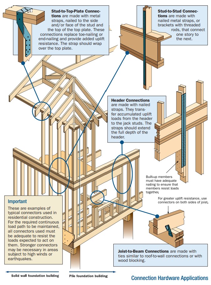
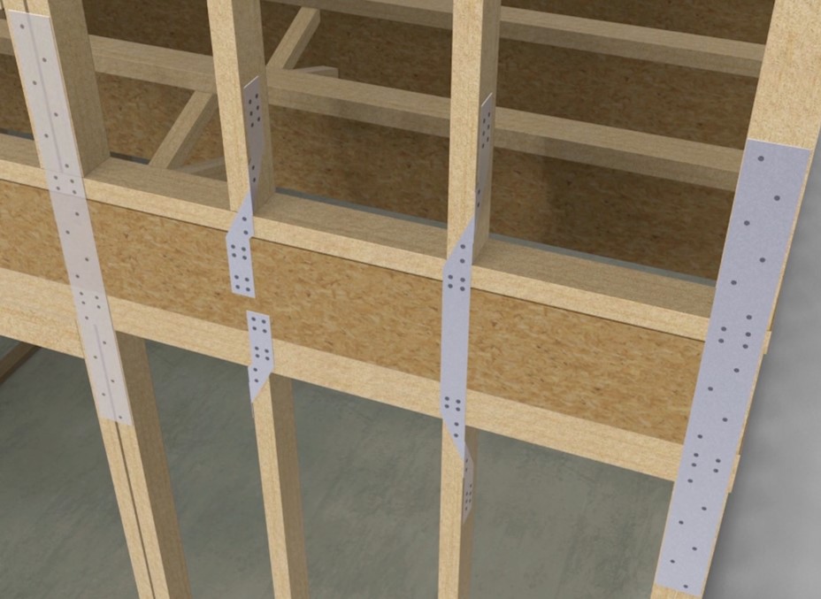
Connecting hardware helps tie the walls to the top plates and rim joists to ensure a continuous load path to improve a building’s resistance to high winds, floods, and earthquakes.
Image

Image
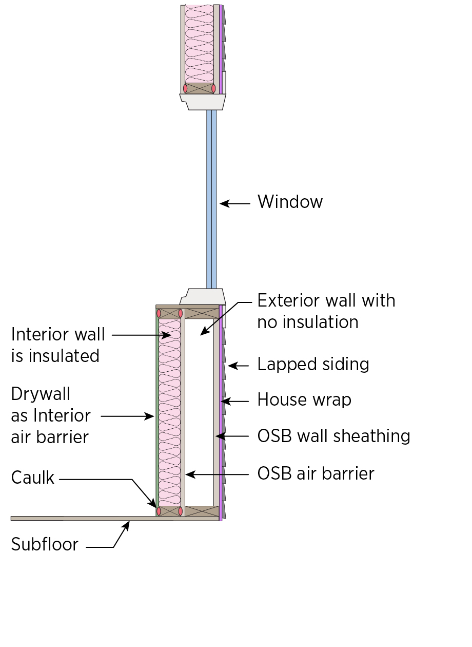
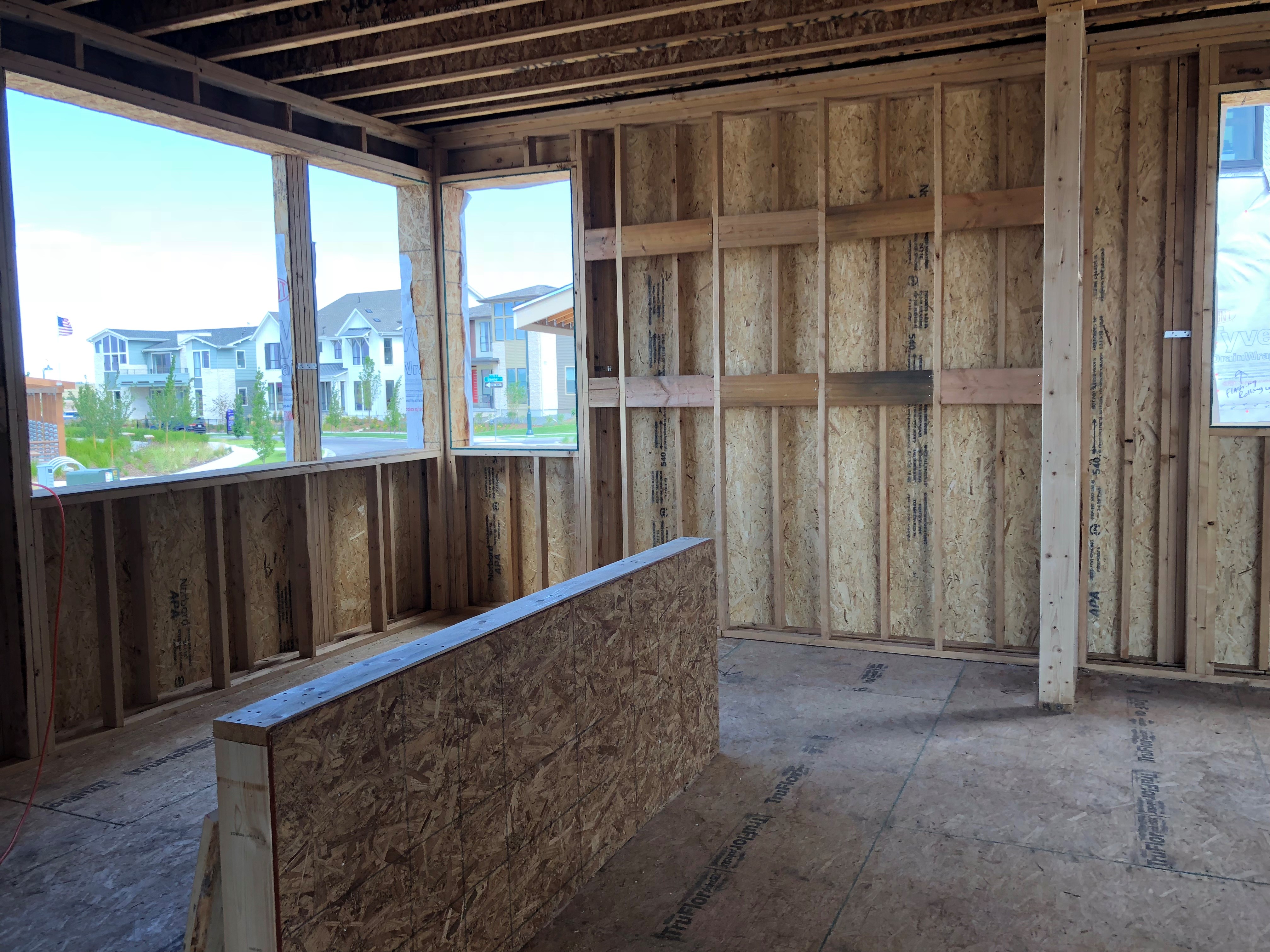
Construct a double wall consisting of two framed walls forming a wide wall cavity for more insulation in the home’s exterior walls.
Image

Image
Image
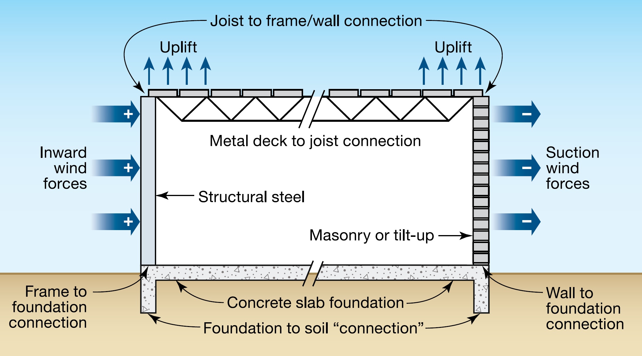
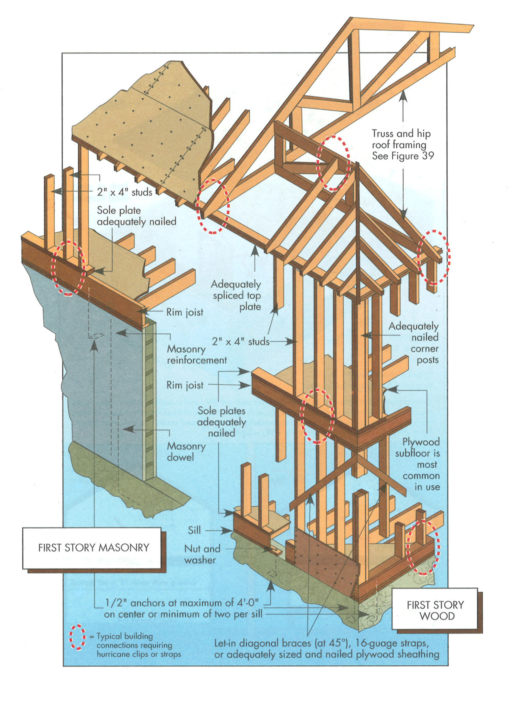
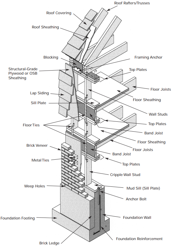
Critical connections for providing a continuous load path in buildings and storm shelters
Image
Image
Image
Image
Image
Image
Image
Image
Image

Image

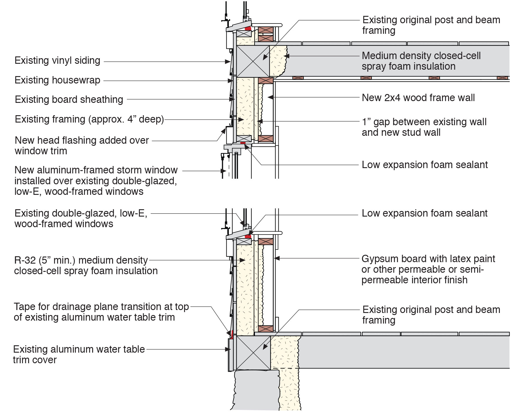
Drywall was removed and the existing 2x4 walls were filled with 3.5 inches of dense-packed cellulose. Outside, the ½-inch plywood was topped with house wrap, 1.5 inches closed-cell rigid foam, 1x3 furring strips, and fiber cement siding.
Image
Each floor of this two-story modular home is constructed in a factory, including the 2x6, 24-inch on-center walls, R-21 fiberglass batt cavity insulation, and rigid exterior foam, housewrap, windows, and trim, then connected on site.
Image
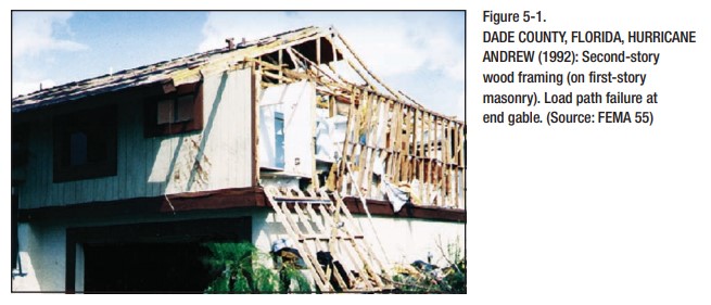
End wall failure under hurricane force winds due to inadequate bracing of the gable end wall.
Image
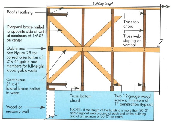
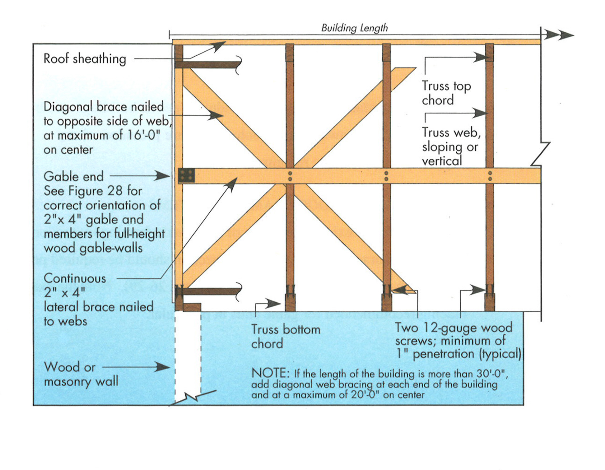
Example A of a gable truss and gable end wall bracing for a home in a hurricane region
Image

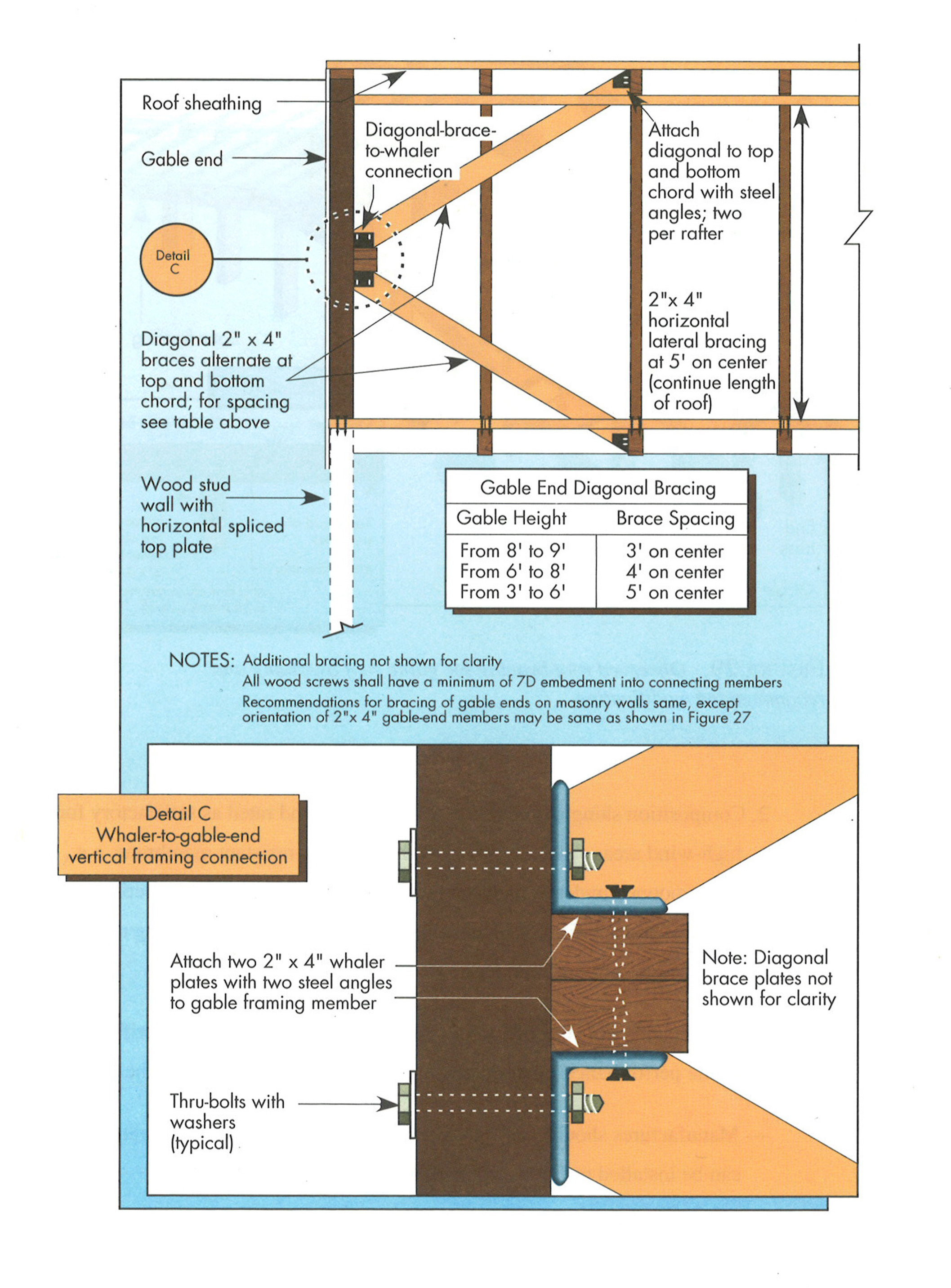
Example B of a gable truss and gable end wall bracing for a home in a hurricane region
Image
Image
Image
Image
Image
Gaps at shared common walls can be a significant source of air leakage in multi-family buildings
Image
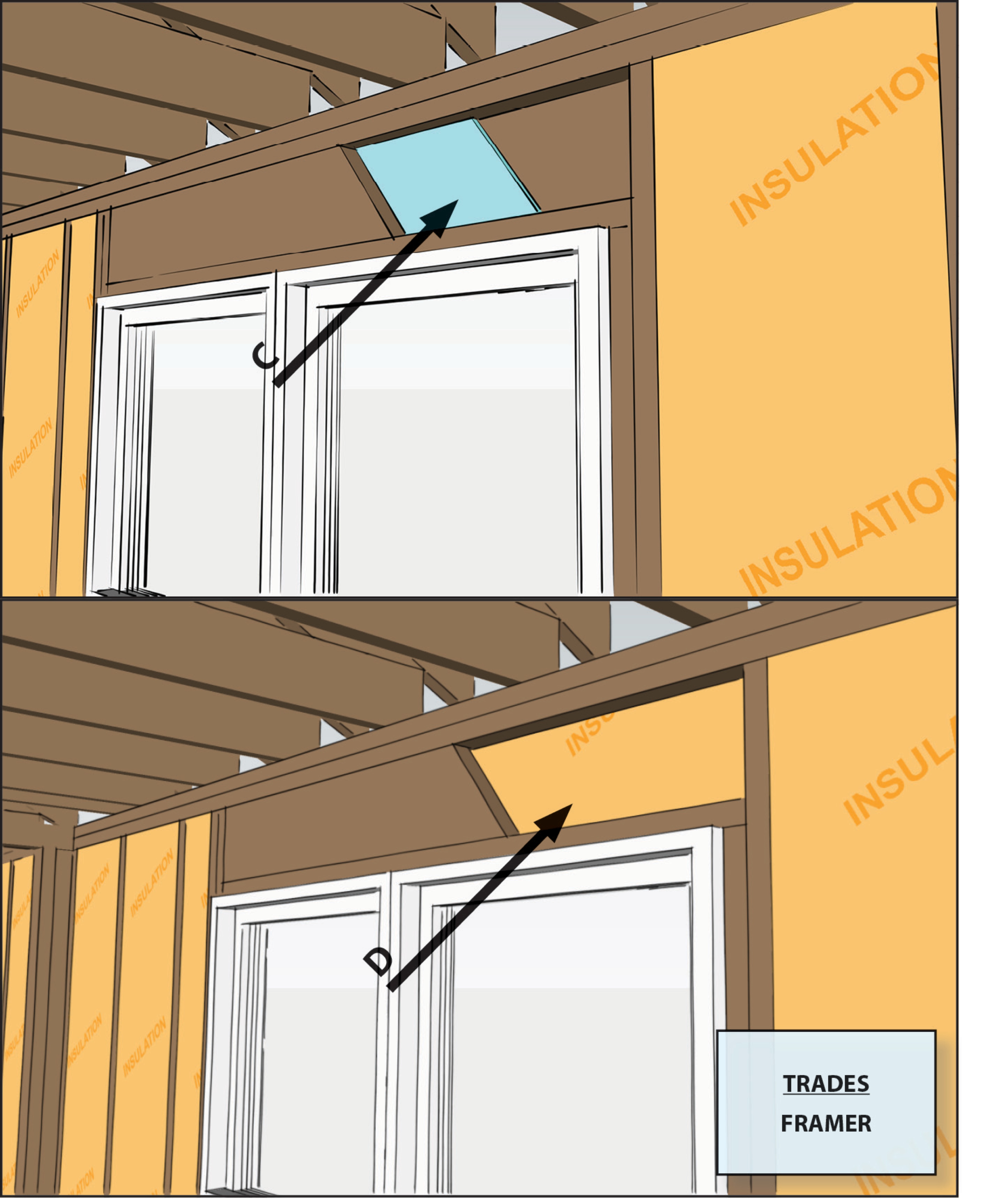
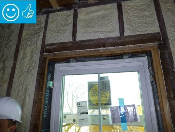
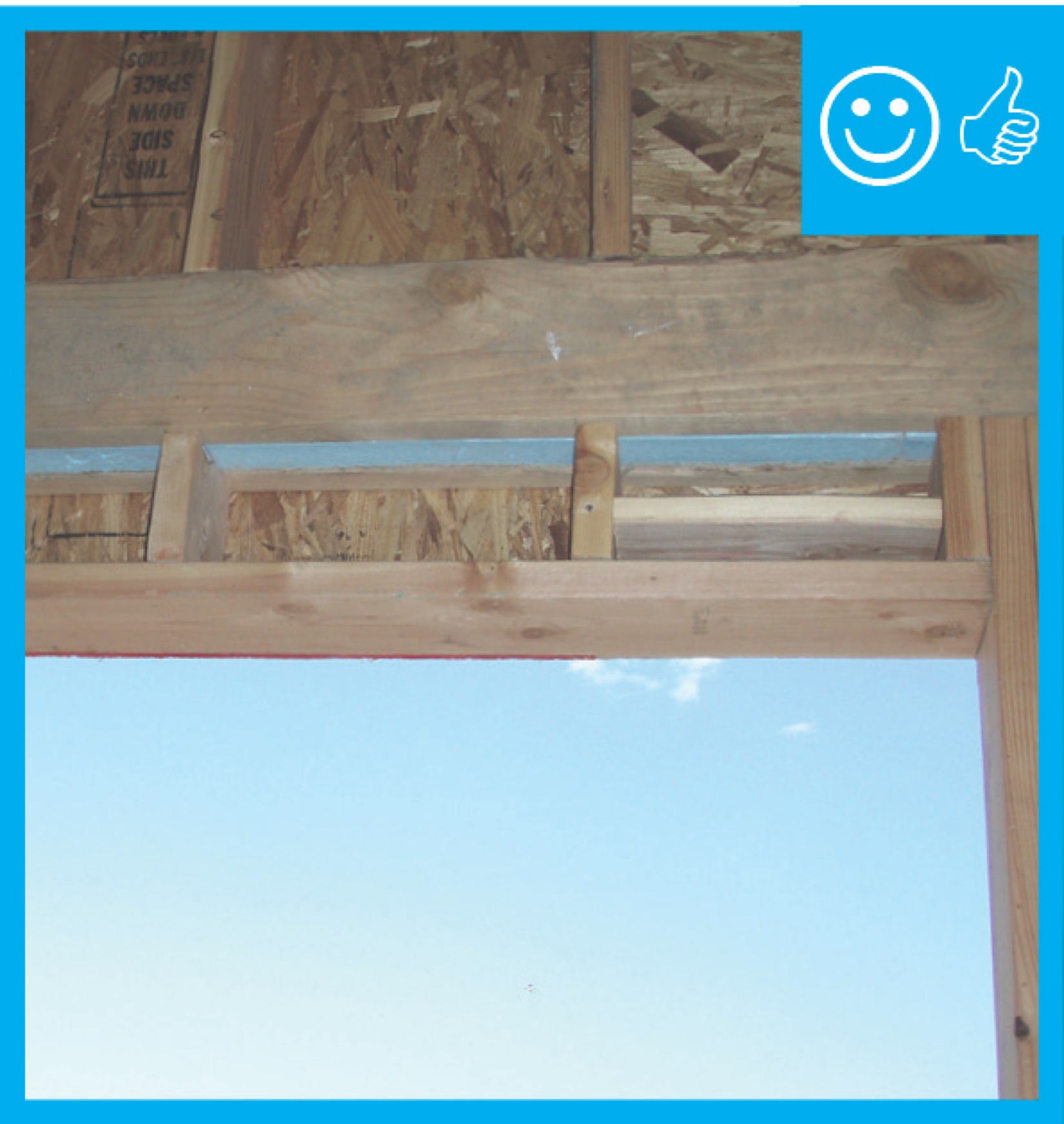
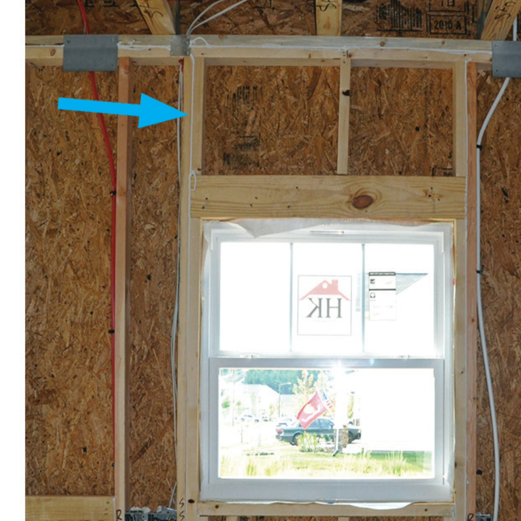
Headers over windows on non-load-bearing walls are open to allow room for insulation.
Image
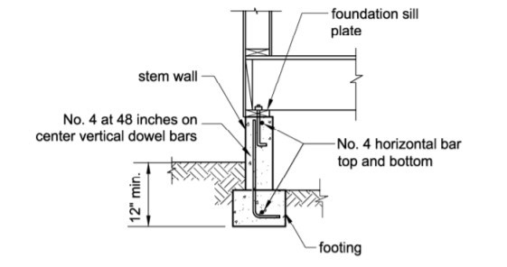
How to properly anchor a new home to its foundation with foundation sill plate, stem wall, and footing
Image
Image
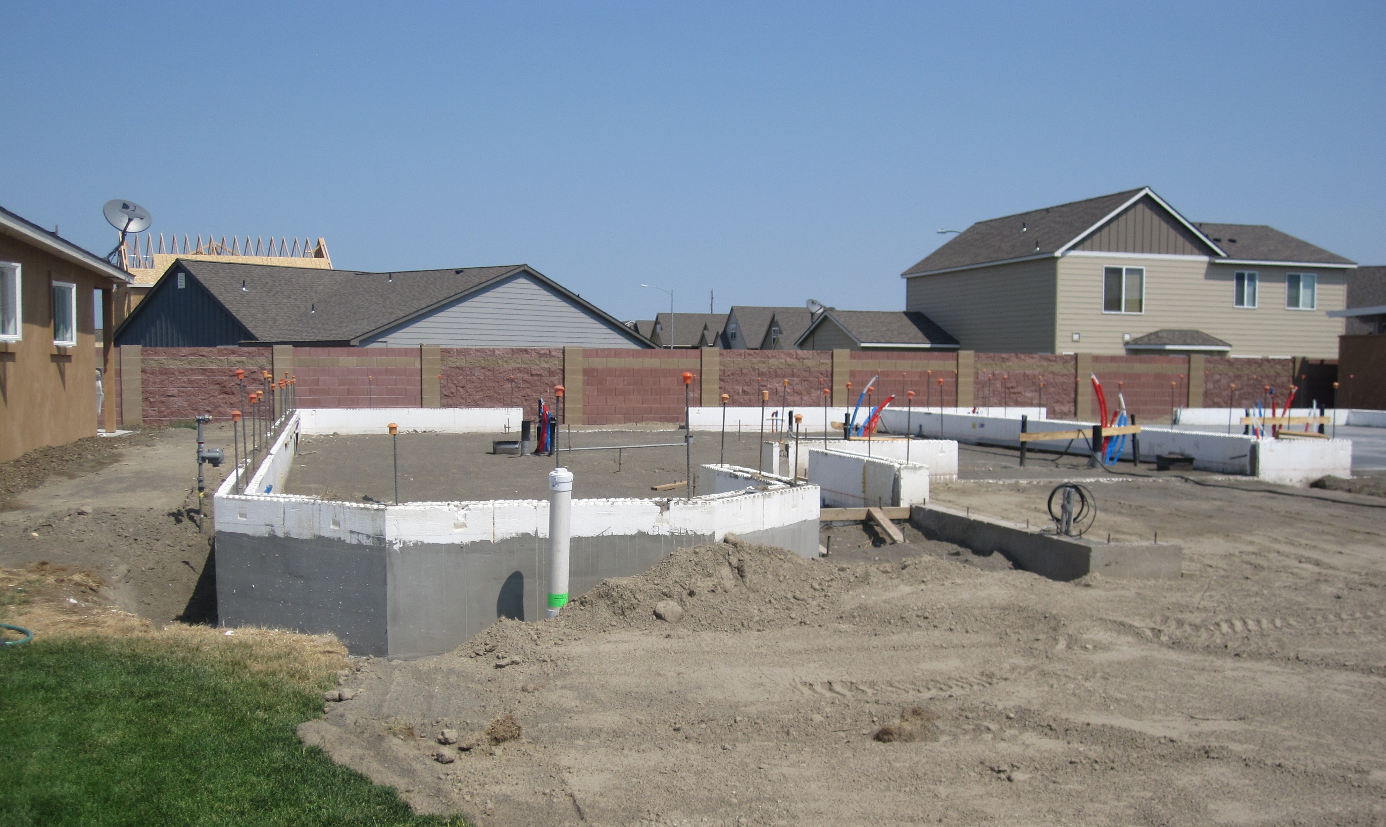
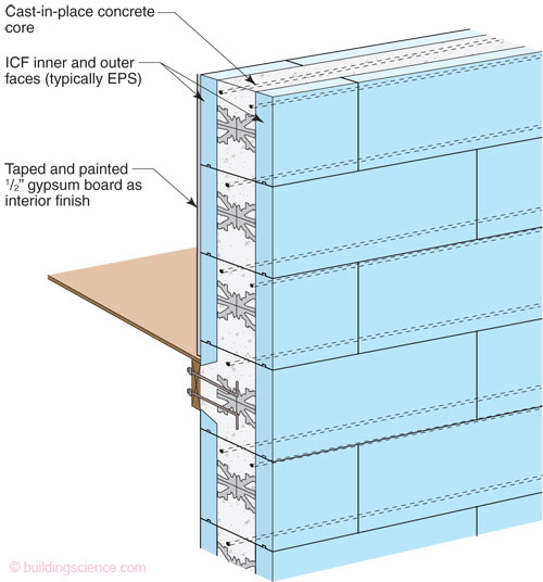
ICFs provide continuous wall insulation from the roof to the footing with very little thermal bridging
Image
Improper continuous load path design lacking bracing results in the failure of gable end walls under high wind conditions.
Image
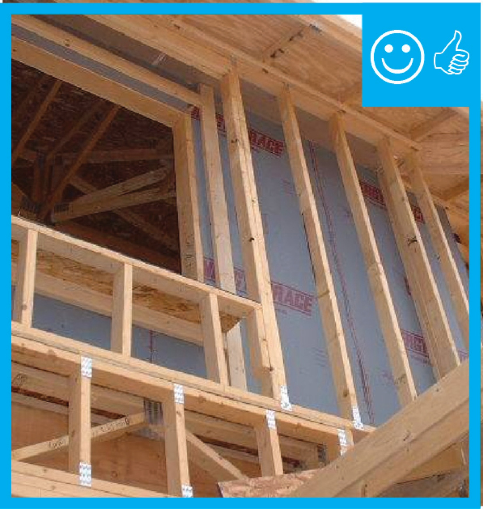
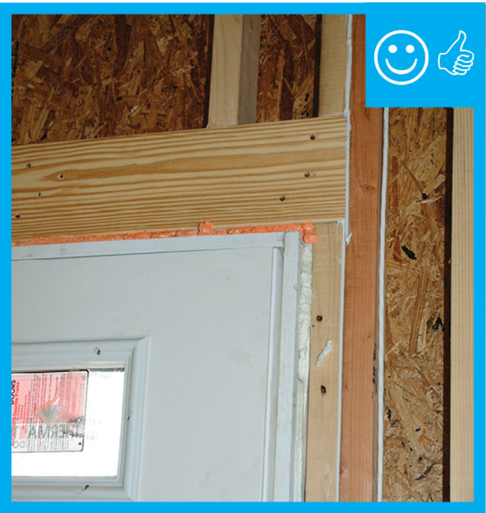
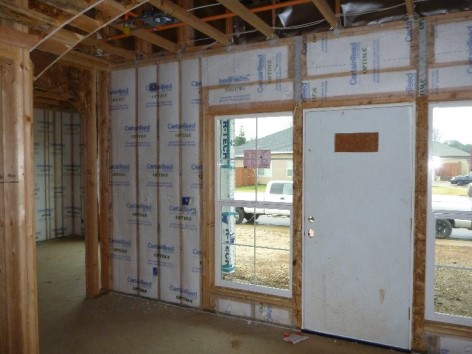
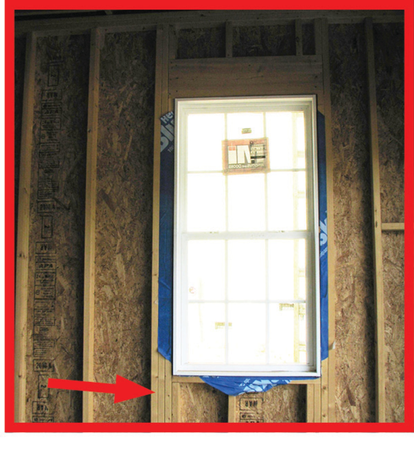
In areas prone to high winds and hurricanes, double vertical “jack trim” and horizontal “header” and “sill” studs are recommended on all sides of window and door openings.
Image
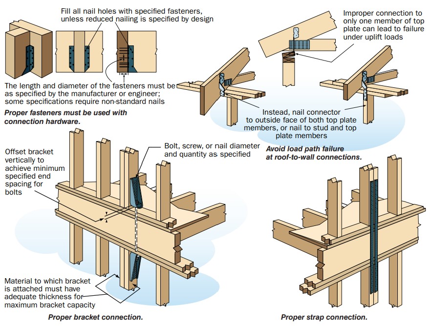
In high-wind regions, special hardware is used for most framing connections; toe-nailing is not acceptable.
Image
Image

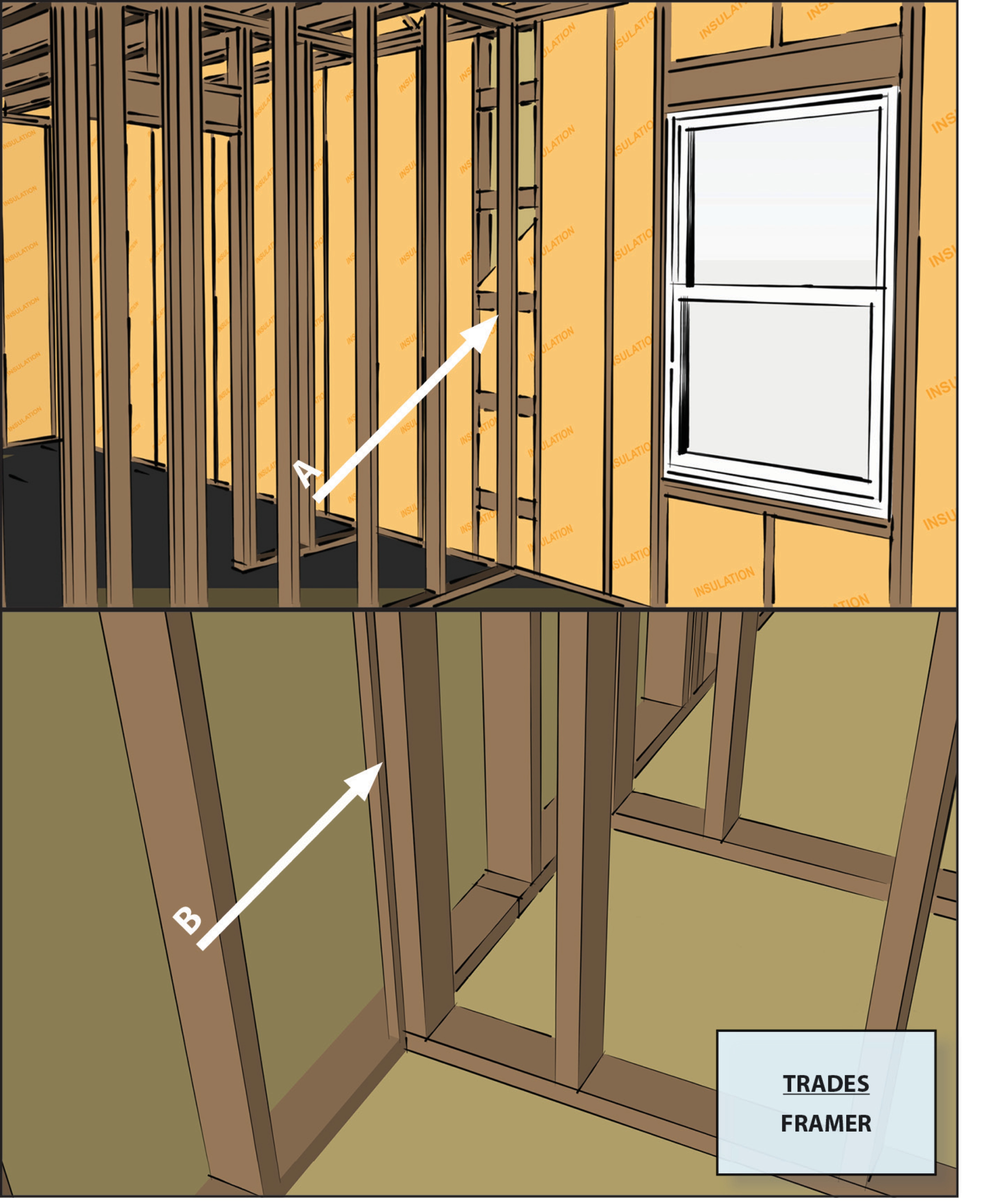
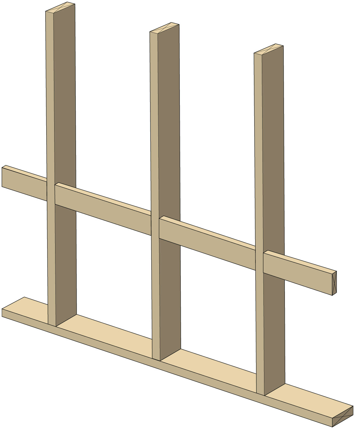
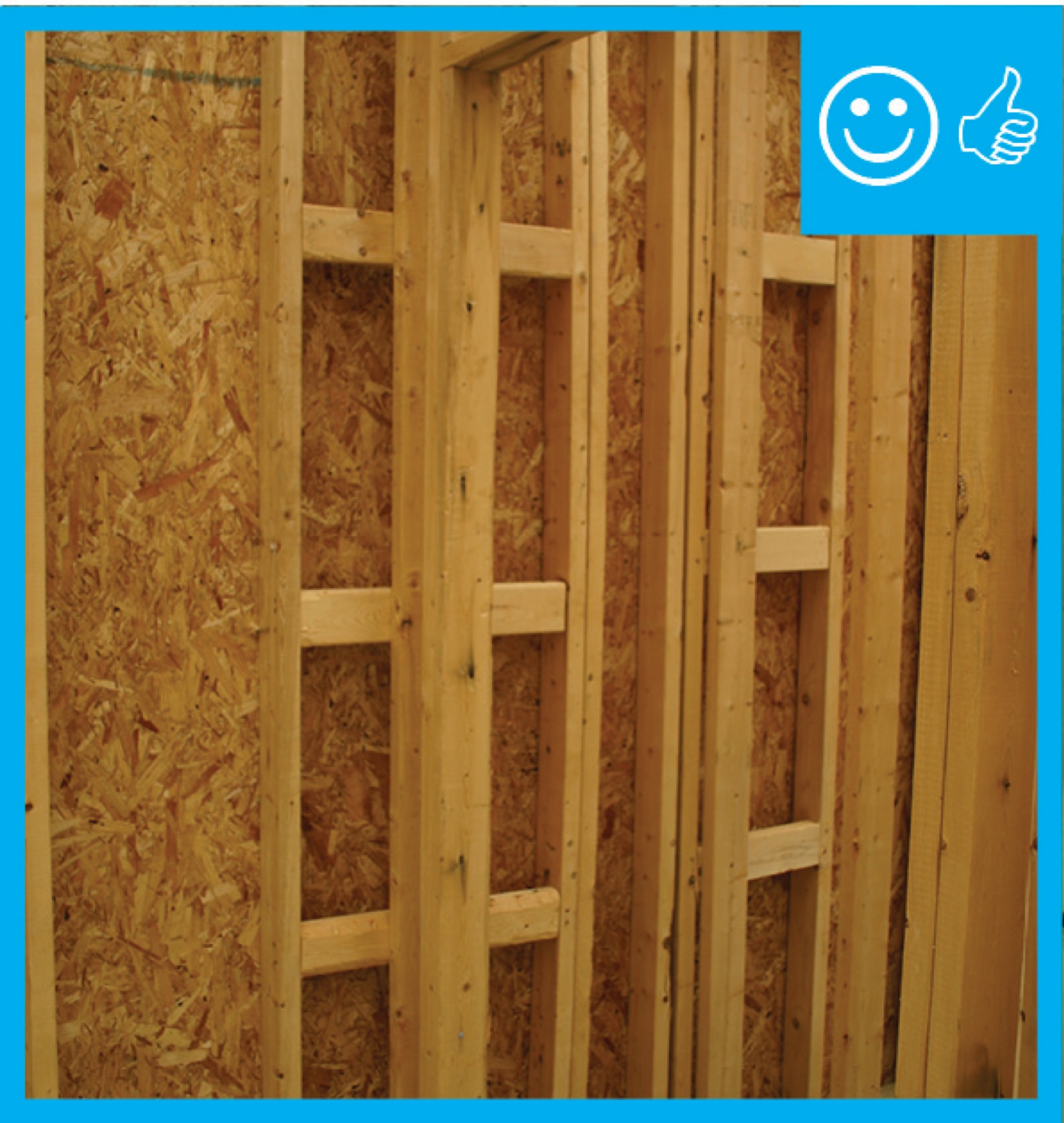
Installing ladder blocking at interior-exterior wall intersections rather than three solid studs in the exterior wall as the supporting surface allows room for insulation in the exterior wall.
Image
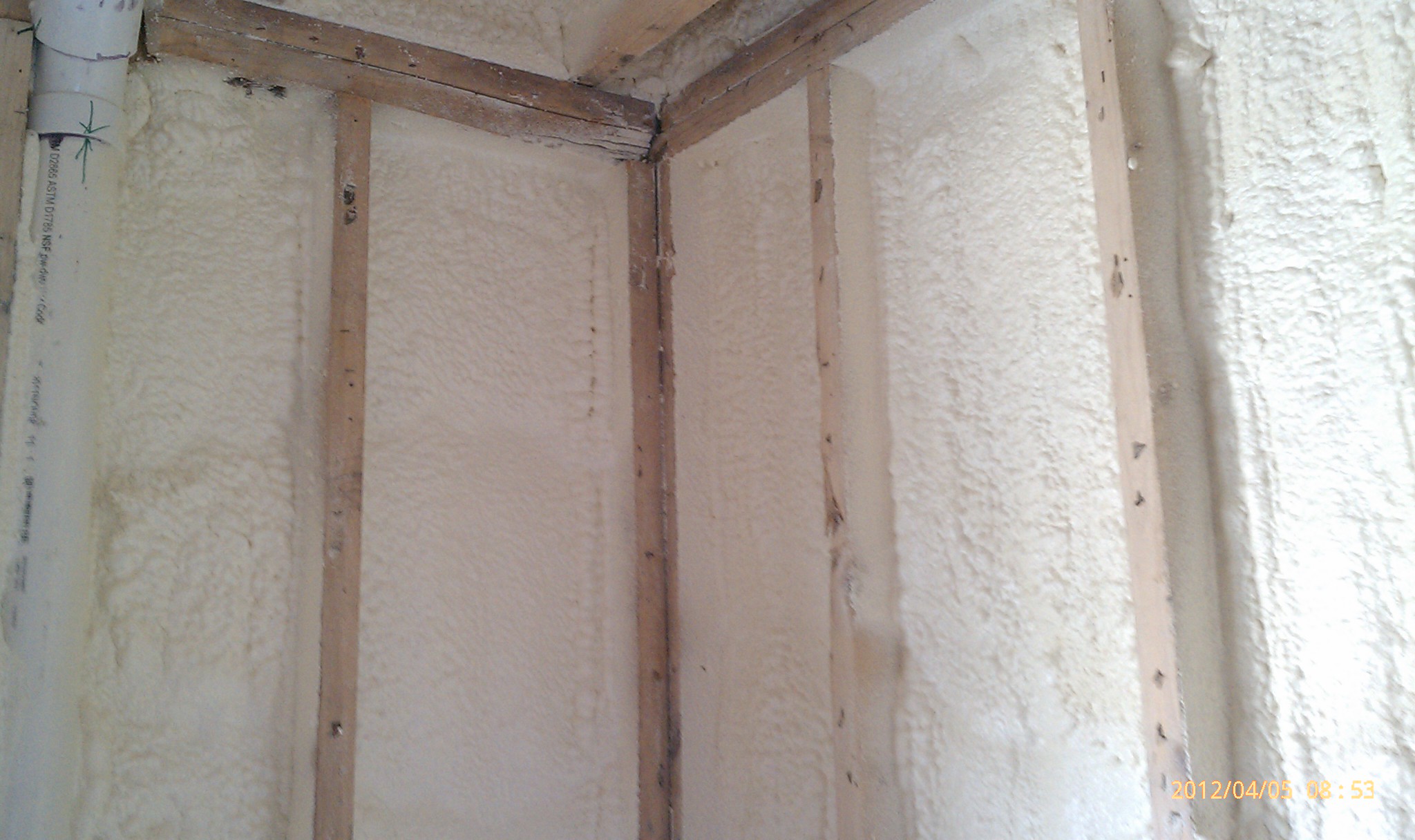
Insulating sheathing is extended up to the roof rafters and sealed around the framing with spray foam as part of this exterior wall retrofit
Image

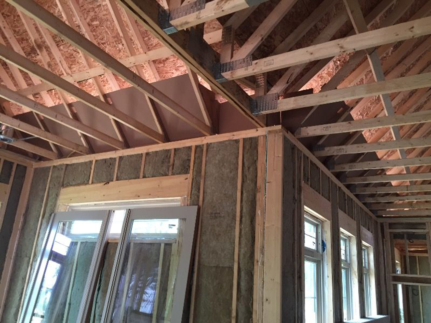
Interior non-load bearing walls are 2x4 studs spaced 24-inchon- center, can have non-structural connectors
Image

Interior wall attached with top plate metal connector, drywall clips support drywall, plan view
Image

Interior wall attached with top plate metal connector, drywall clips support drywall, side view
Image
Image

Image
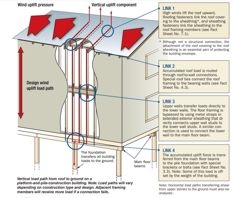
Key connection points for a continuous load path for earthquake and high wind disaster resistance
Image
Image
Ladder blocking where interior and exterior walls intersect uses less wood and provides more room for insulation than stacking studs in the exterior wall to nail the interior wall to.
Image

Image

Image
Ledger board, metal brackets, and vertical 2x4s have been installed in preparation for exterior spray foam in this retrofit exterior wall insulation technique
Image

Image
Image
Image
Image

Image
Reduce thermal bridging in hot climate zones by using an intersecting exterior wall framing technique as shown here.
Image

Right - A continuous load path connects the roof and wall framing to the foundation.
Image

Right - A floor-to-floor hold down can be installed as a retrofit without removing the siding.
Image
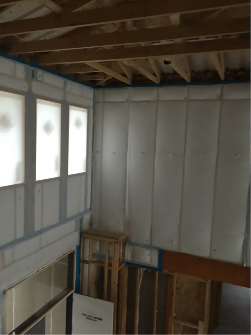
Right - Closed-cell spray foam insulation fills the wall cavities of the exterior walls in this home retrofit
Image
Image

Right - Engineered portal frames are used for wall bracing to resist wind and earthquake loads.
Image
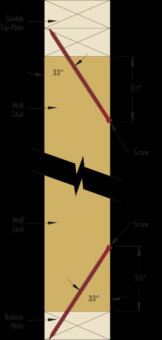
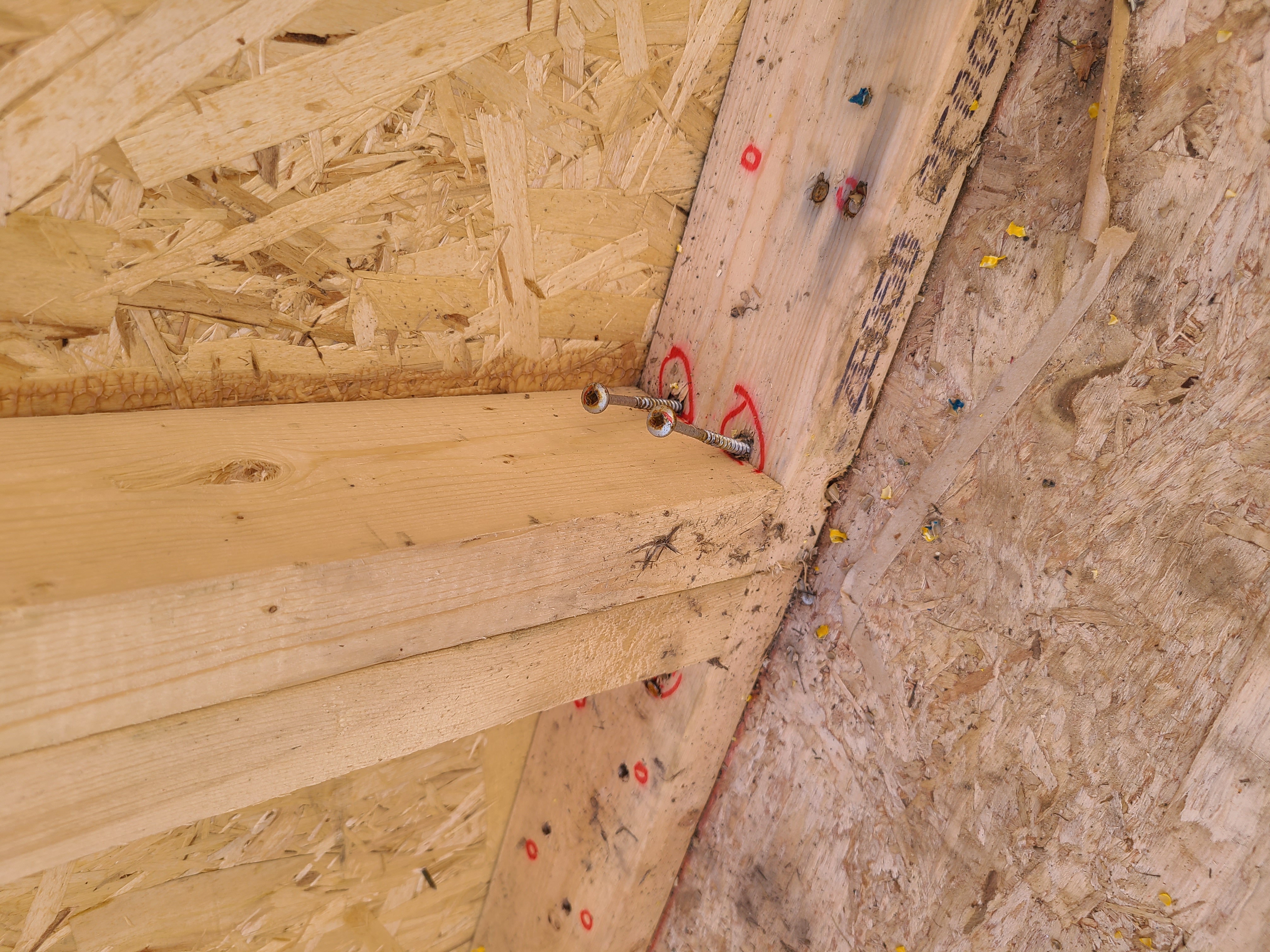
Right - Engineered structural screws are installed to secure a stud to a top and bottom plate for increased hurricane or seismic resistance.
Image
Right - Installation steps for the L-bent strap method of bracing a gable end wall
Image
Right - Metal connectors provide uplift resistance at the rim joist between floors in new construction for a continuous load path.
Image
Right - Metal connectors provide uplift resistance at the stud-to-bottom plate connection in new construction for a continuous load path.
Image
Right - New flashing has been installed to complete the air and water control layers at the window openings of this wall retrofit that includes insulating the wall cavities with spray foam
Image
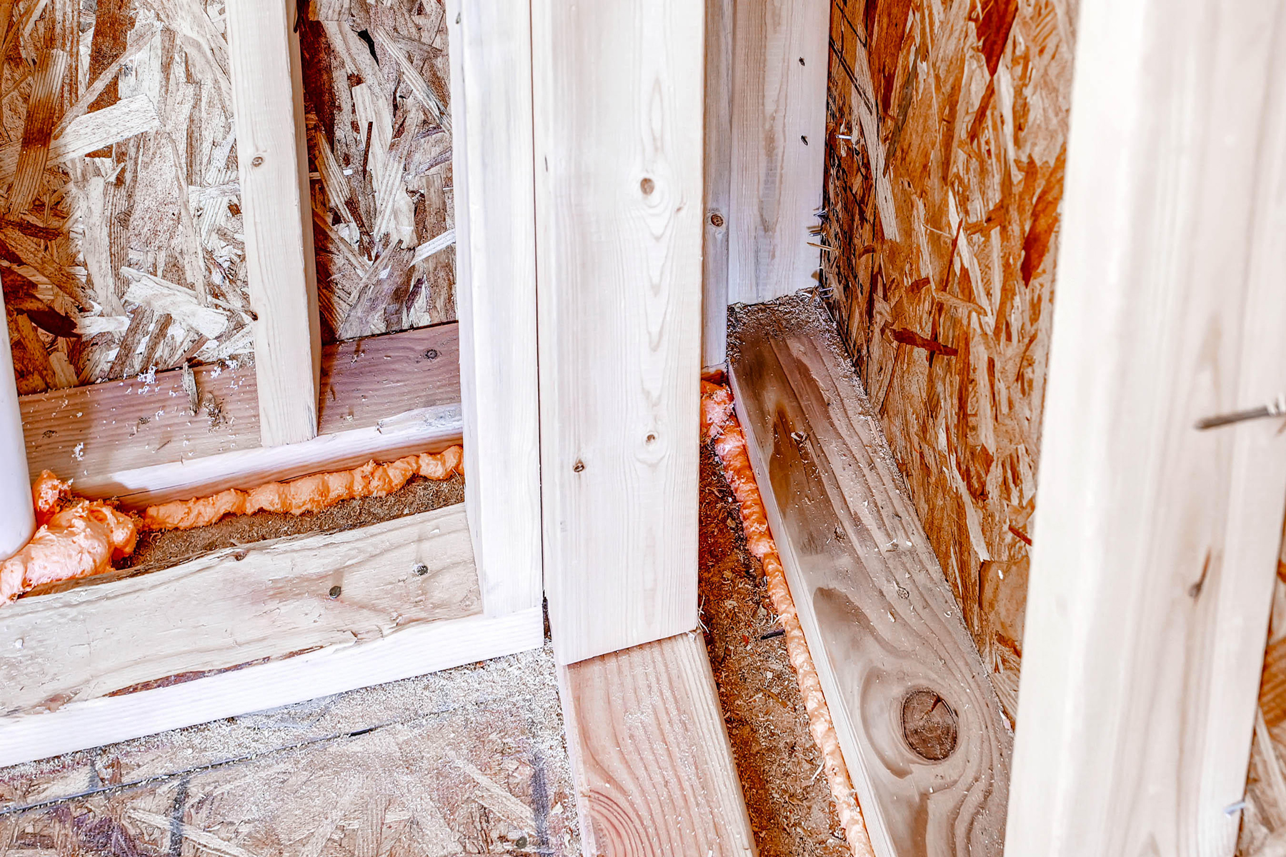
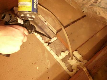
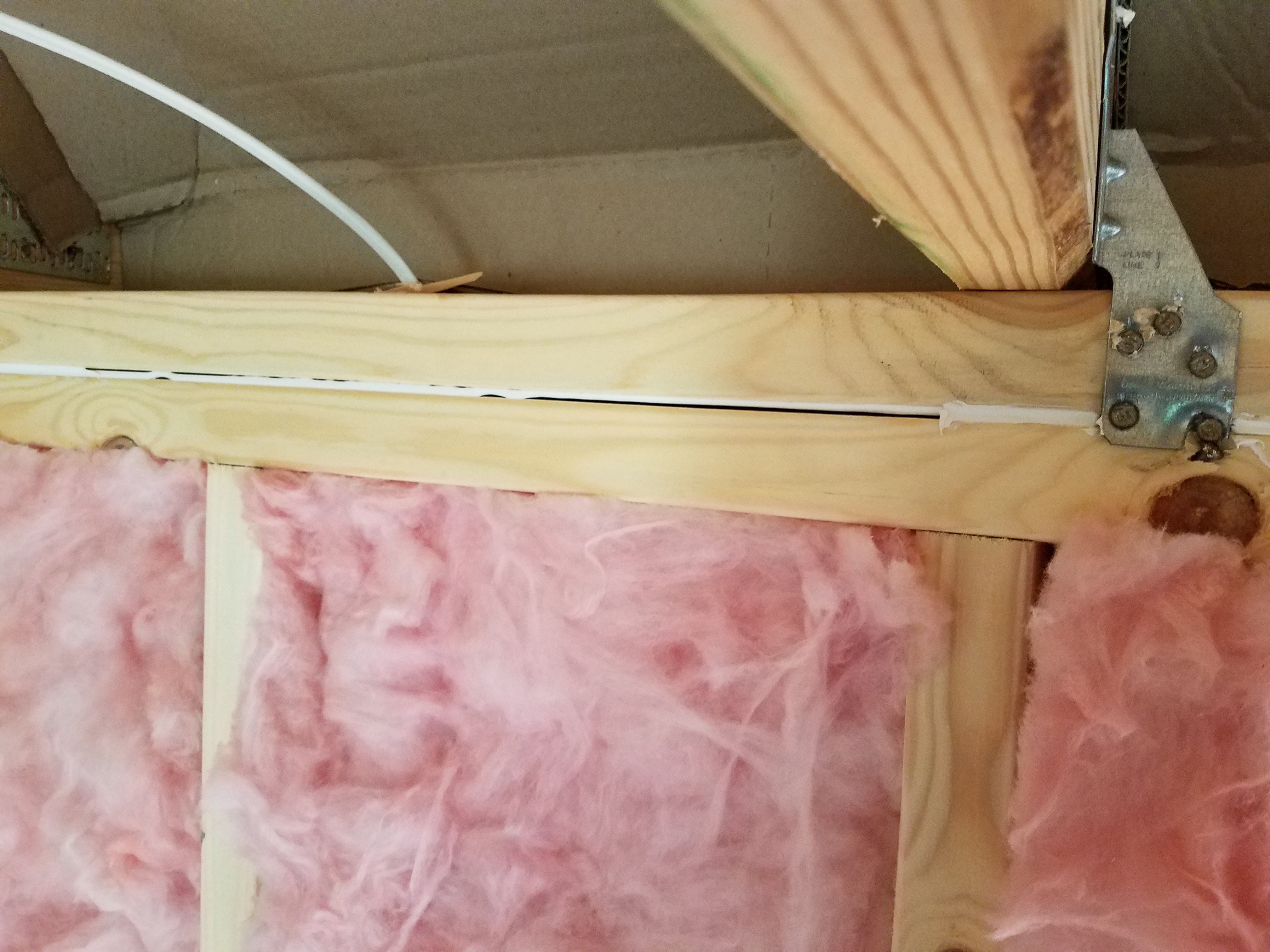
Right - Spray foam fills the walls and rim joists to air seal and insulate while caulk seals the framing joints.
Image

Right - The wall framing is connected to roof framing with metal ties for hurricane-resistant construction.
Image
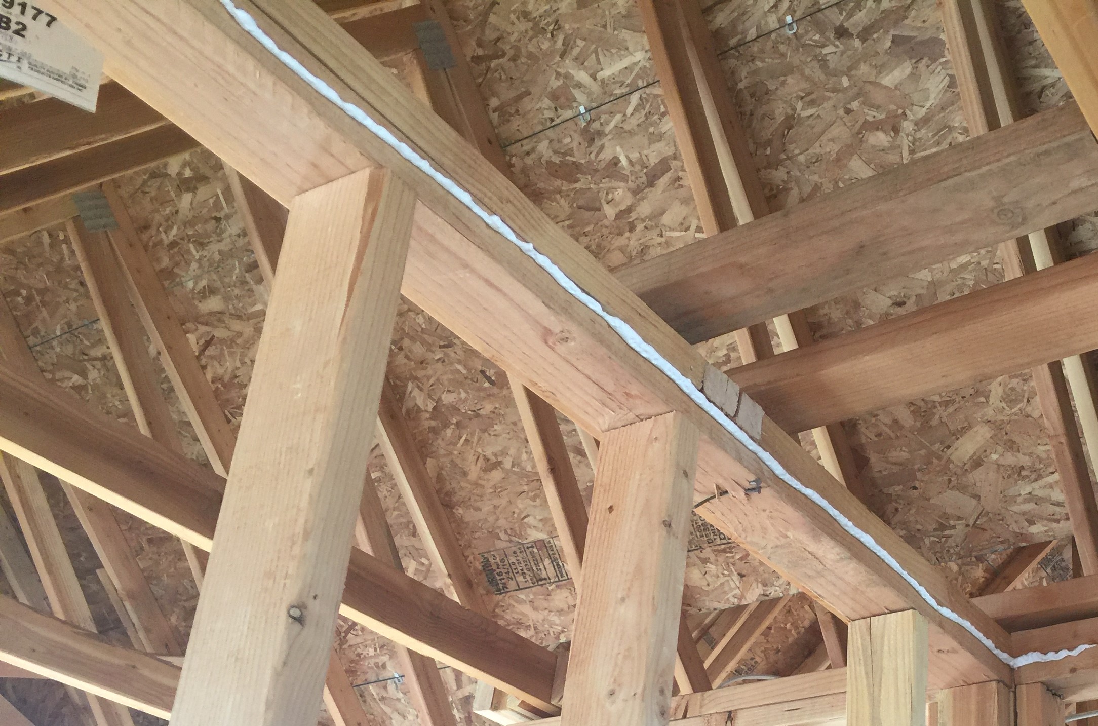
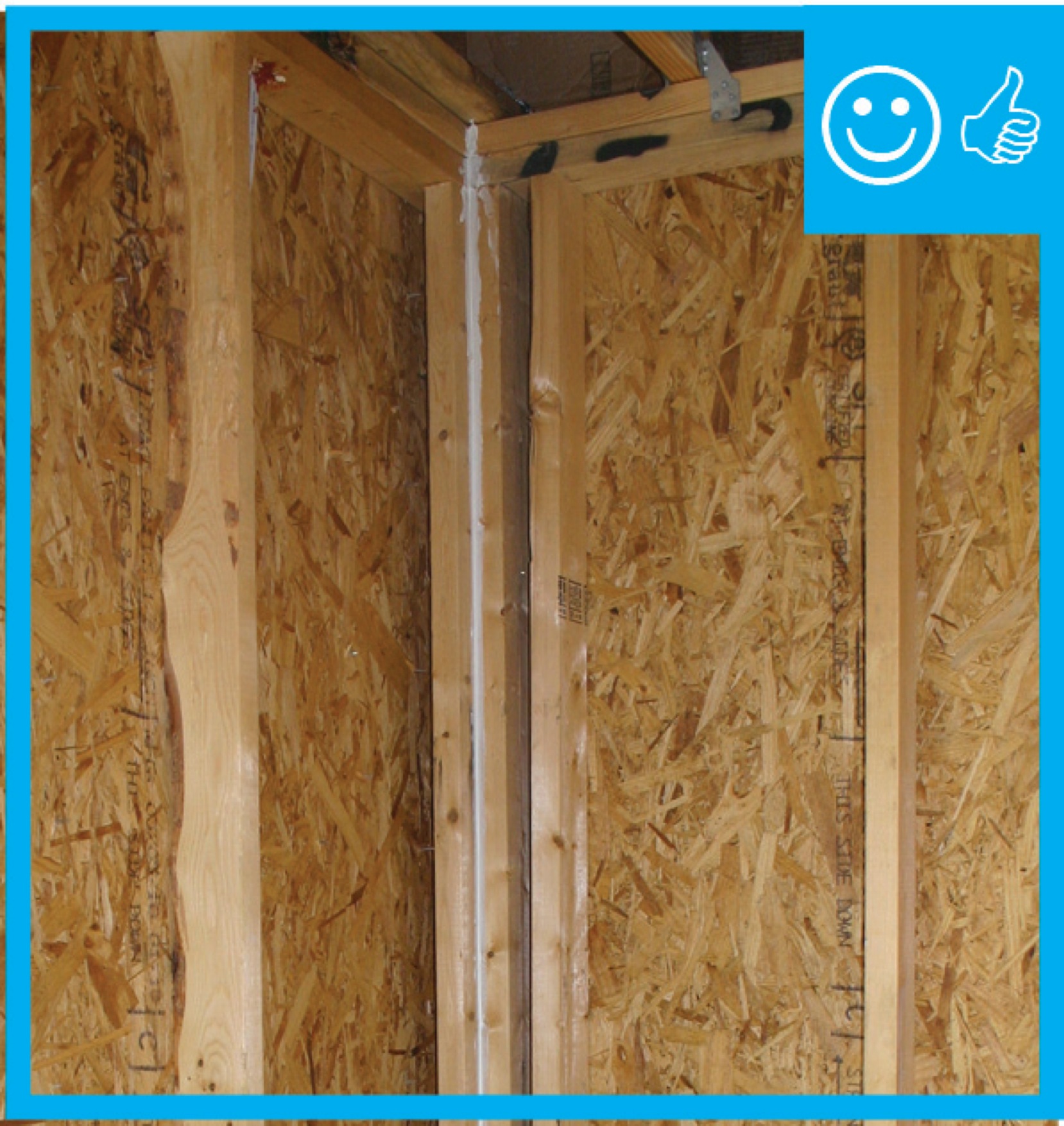
Right – A bead of sealant will form an airtight gasket between the top plate and drywall.
Image
Image

Right – A gap separates the two wall layers in this double-stud wall assembly allowing room for insulation to stop thermal bridging between the inner and outer wall
Image
Image
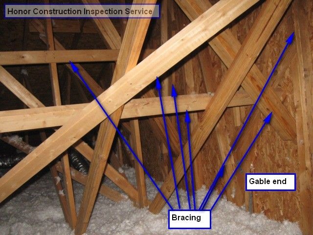
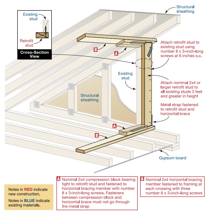
Right – An existing gable wall is reinforced with horizontal braces that butt up to the gable end wall and connect back to multiple trusses; retrofit studs make full contact with the wall and the compression blocks and are connected to the horizontal brac
Image
Image
Right – Appropriate use of framing members to support double windows and additional cripples for drywall purposes
Image
Image
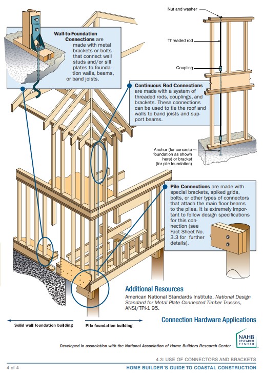
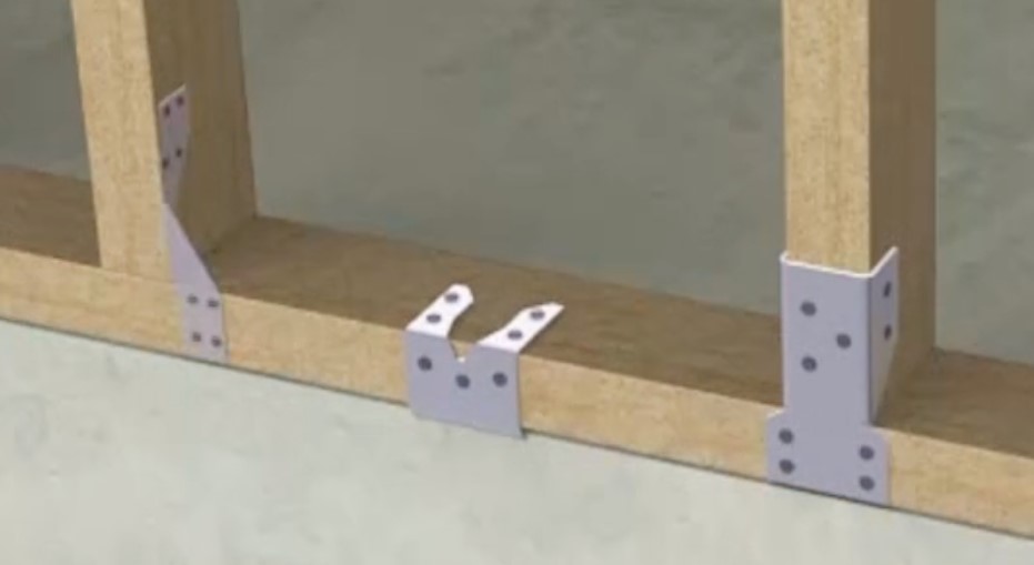
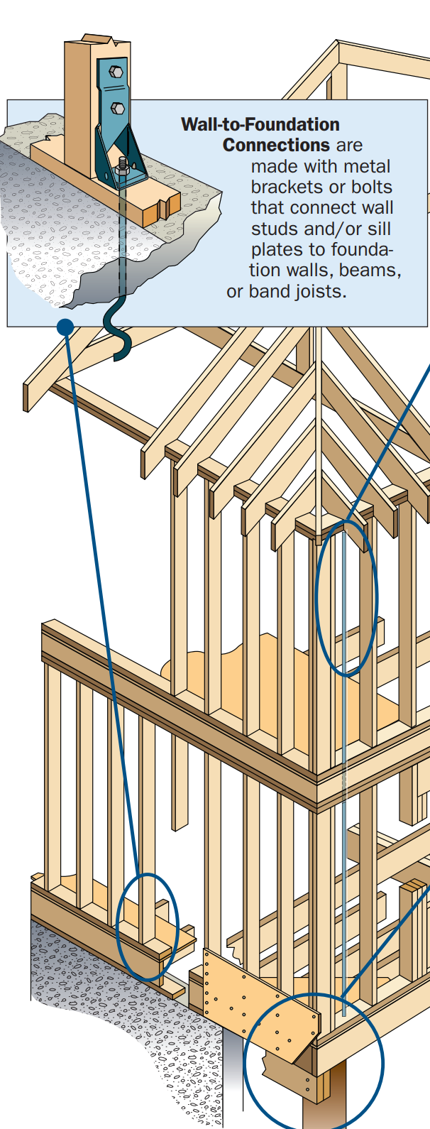
Right – Examples of wall stud to sill plate and foundation and wall rod connectors and brackets.
Image
Right – Examples of wall stud to top plate and stud to rim joist framing connectors and brackets.
Image
Right – Foam gasket is installed on the surface of the framing before plywood sheathing is installed on these factory-constructed wall panels.
Image
Image

Image
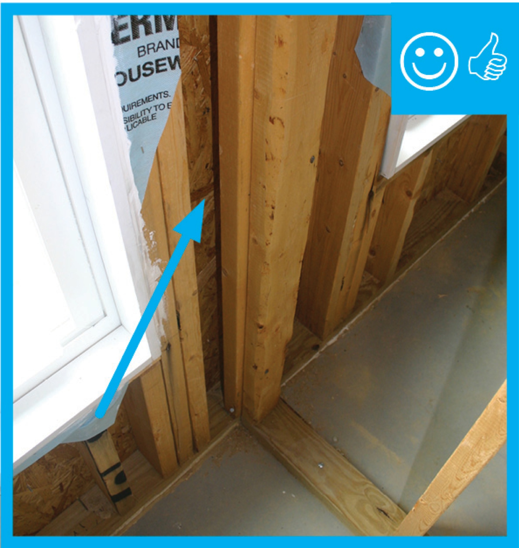
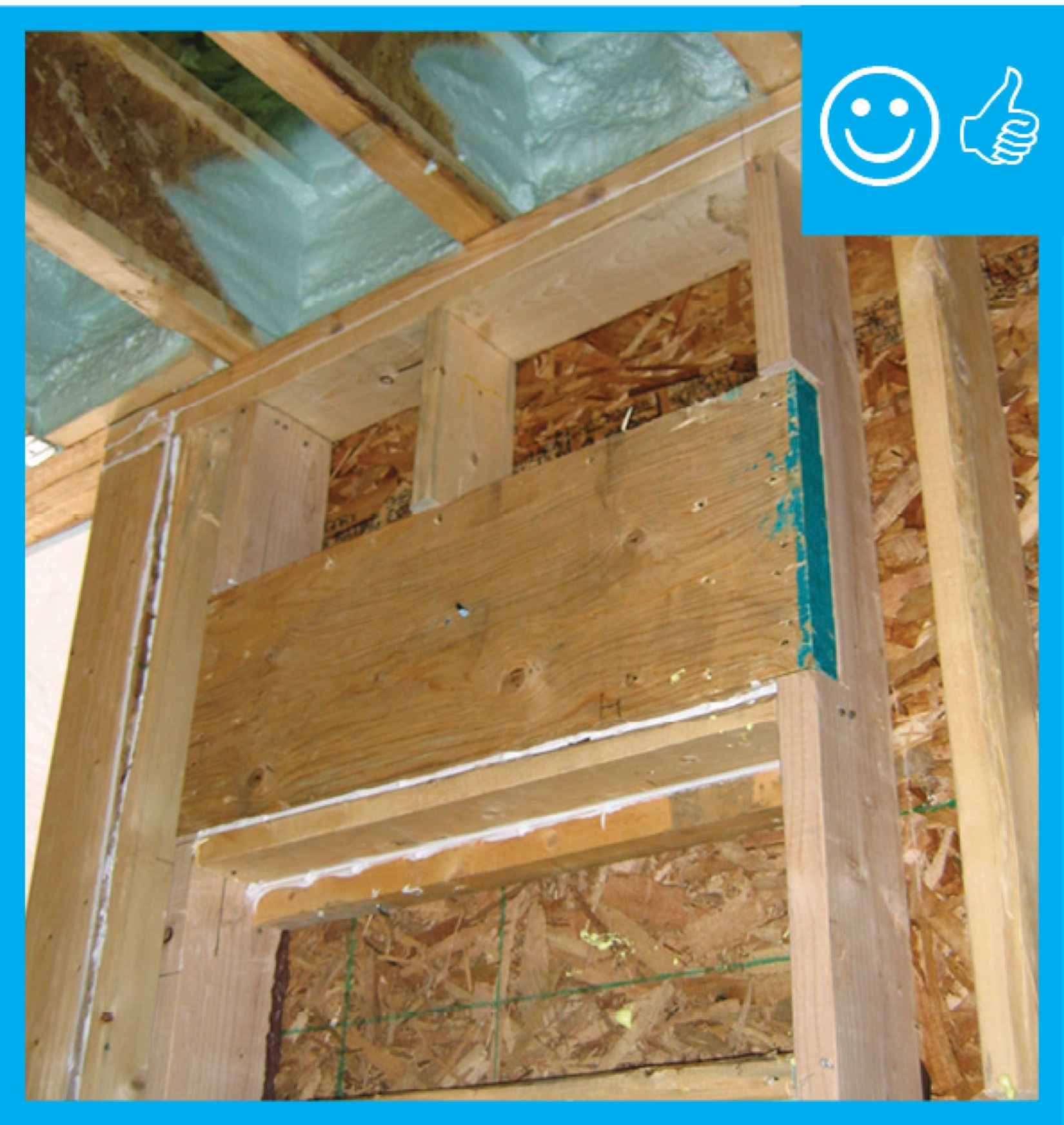
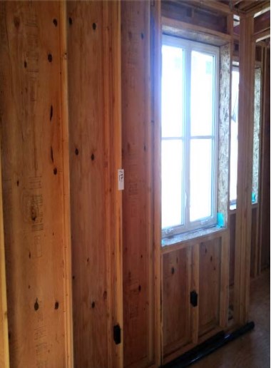
Right – Full length 2x6 nailer has been installed to allow space for insulation at wall intersection
Image
Image
Image
Image
Right – Ladder blocking allows the exterior wall to be insulated where intersected by an interior wall.
Image
Image
Image

Image
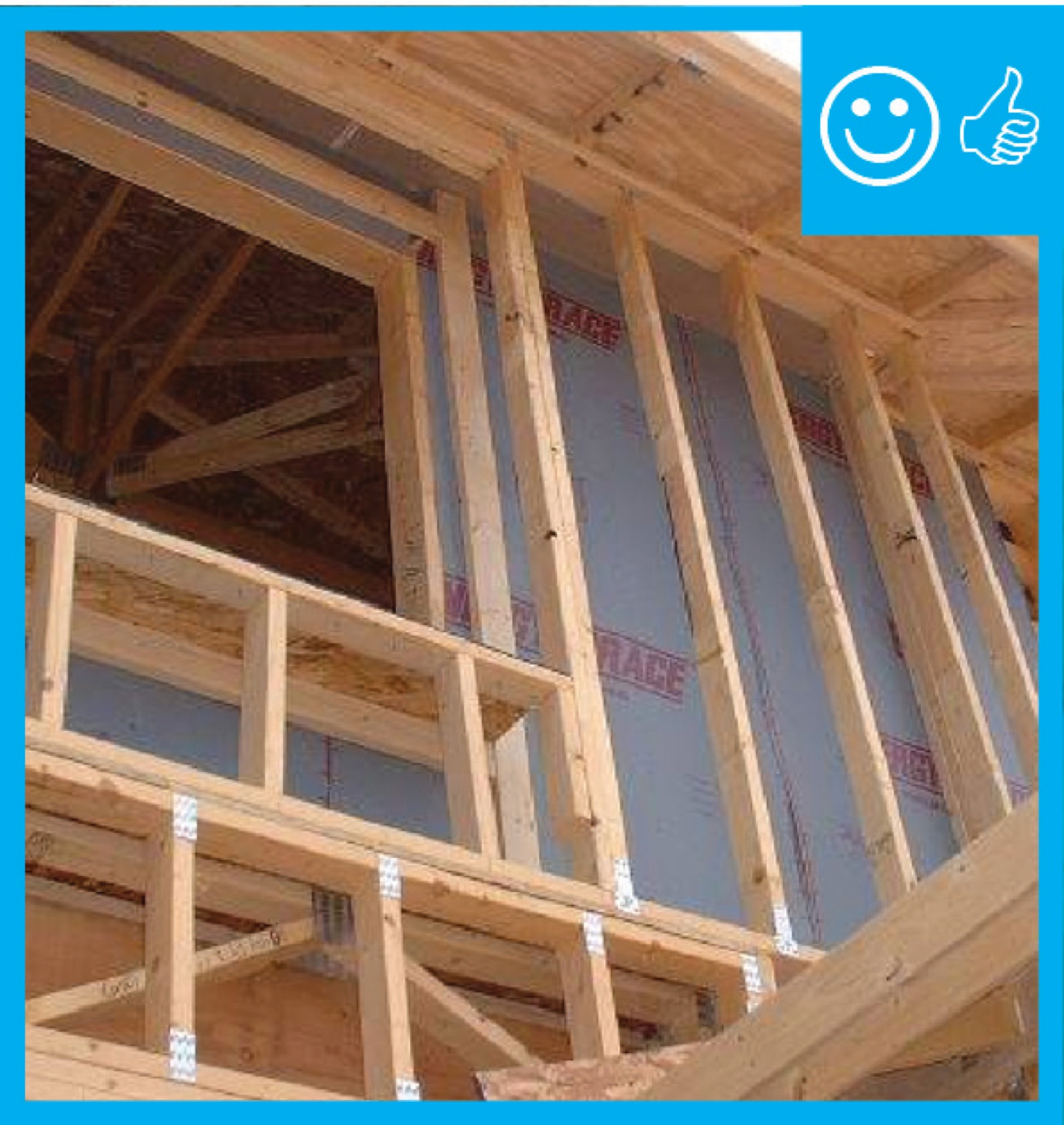
Right – Rigid air barrier installed between double-wall assembly. Inside cavity will be insulated
Image

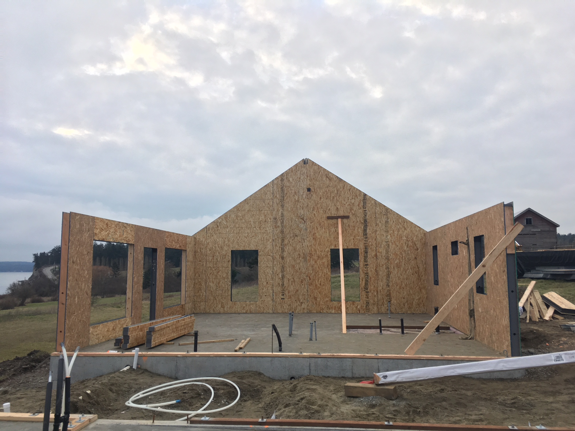
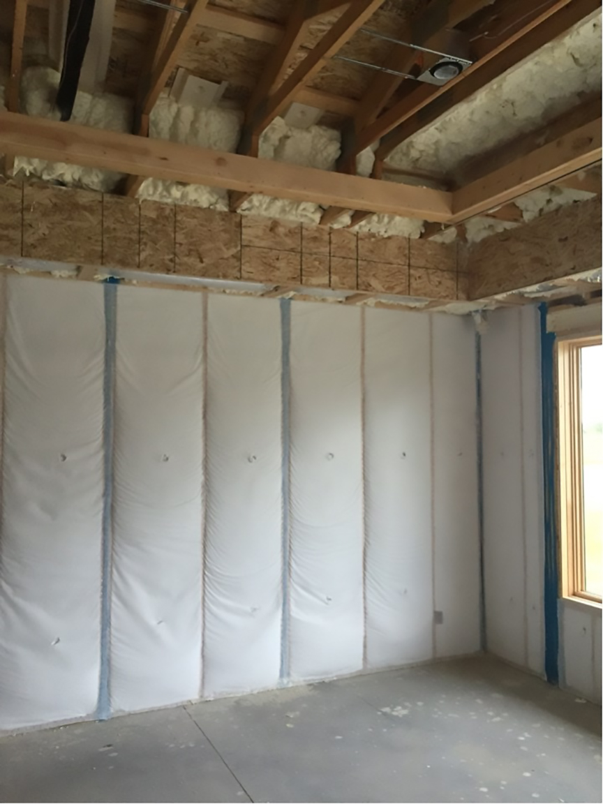
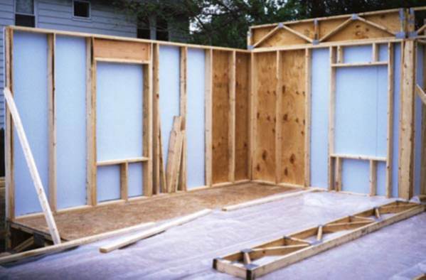
Right – This home is framed with double walls – two 2x4 walls set next to each other then sheathed with OSB on the exterior and netted on the interior face to create an extra-deep wall cavity that can be filled with blown-in insulation.
Image
Image
Image
Image
Image

Image
Image
Image
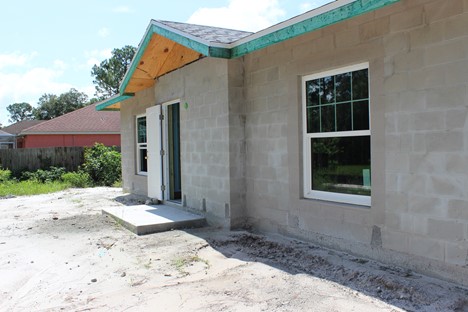
Right- This house uses CMU construction for flood and termite resistance as well as thermal mass
Image
Image
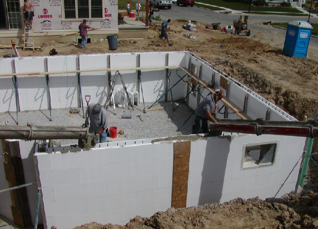
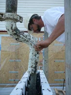
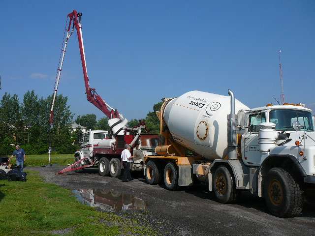
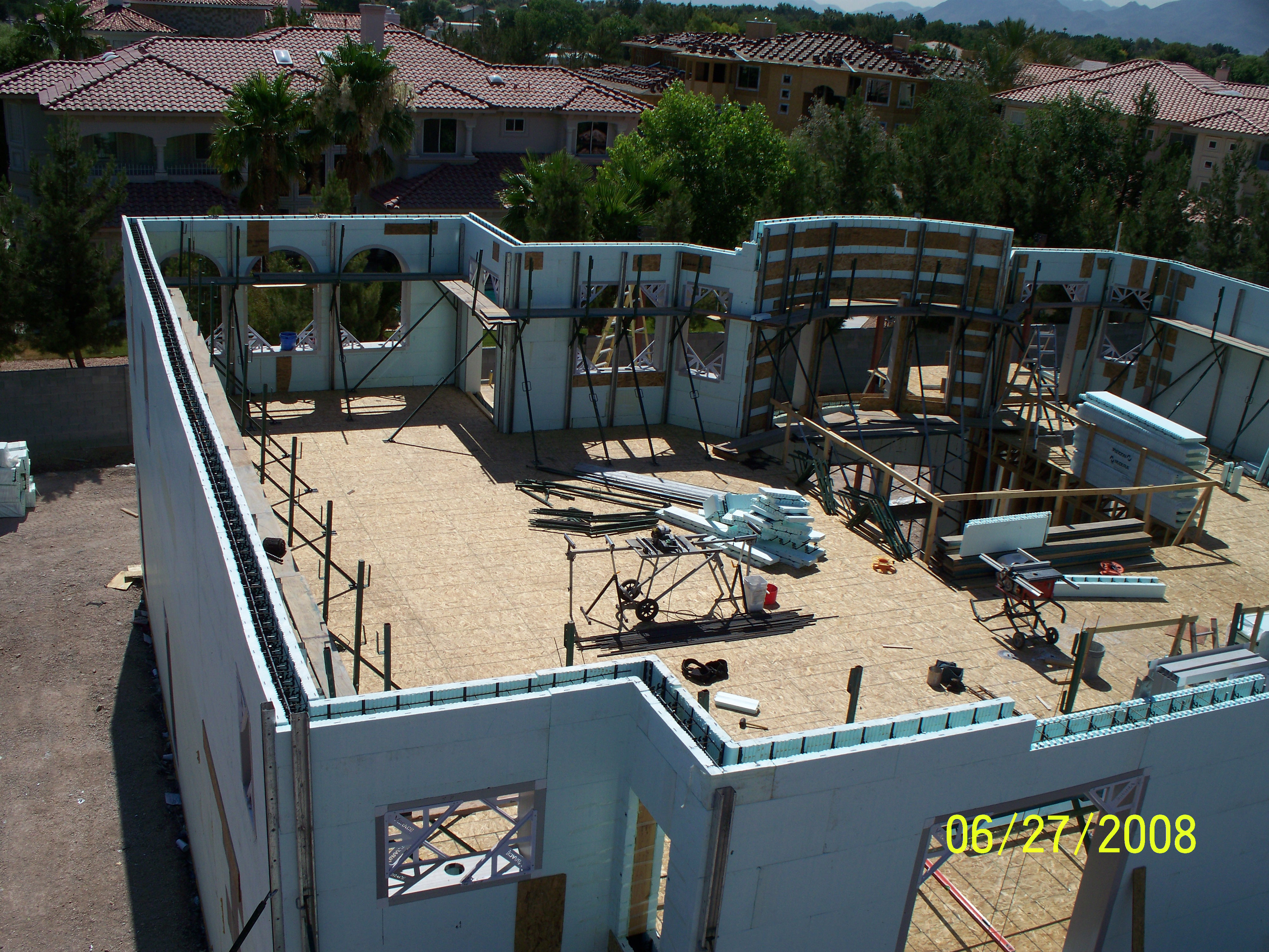
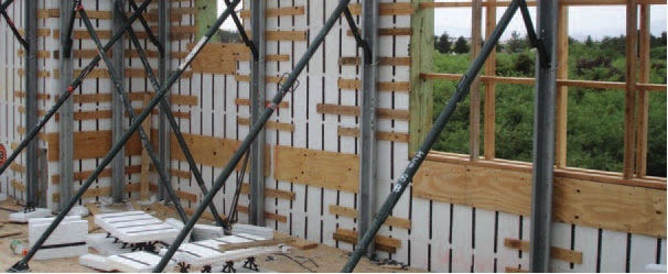
Scaffolding is continually raised as courses of foam brick are added so that the pour man can see both sides of the wall during the pour.
Image
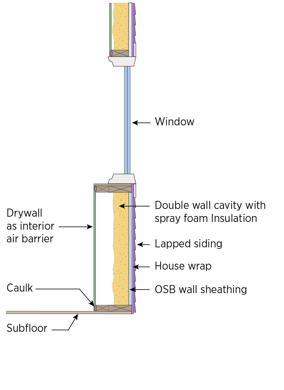
Single framed wall converted to double wall and insulated with closed-cell spray foam
Image
Solid wood blocking was installed in the walls to accommodate future grab bars in both bathrooms.
Image
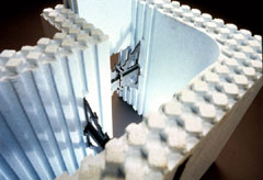
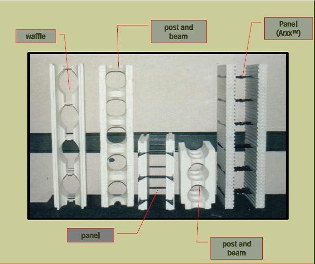
Special molded corners provide continuous insulation layer at the corners to improve structural strength and minimize thermal bridging
Image
Structural insulated panels offer a continuous layer of thermal protection and draft resistance around the home and come from the factory precut for fast assembly.
Image
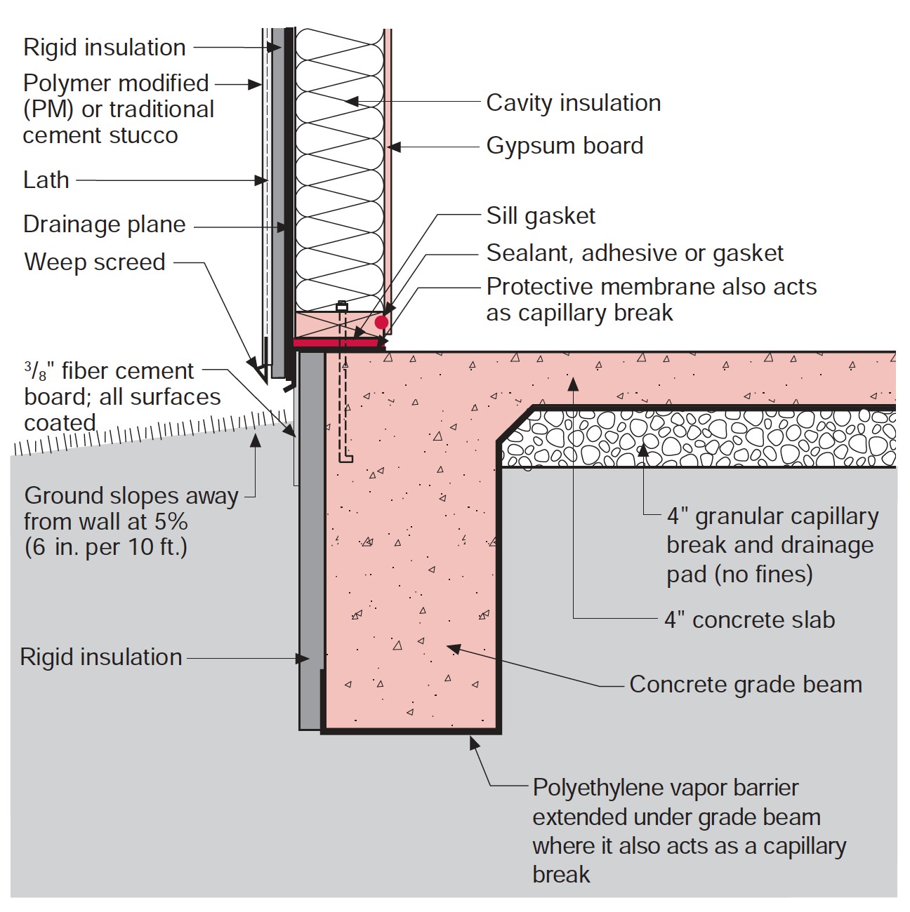
Stucco is installed over rigid insulation, which is installed over a drainage plane consisting of a drainage gap and building wrap layer over the sheathing
Image
Image

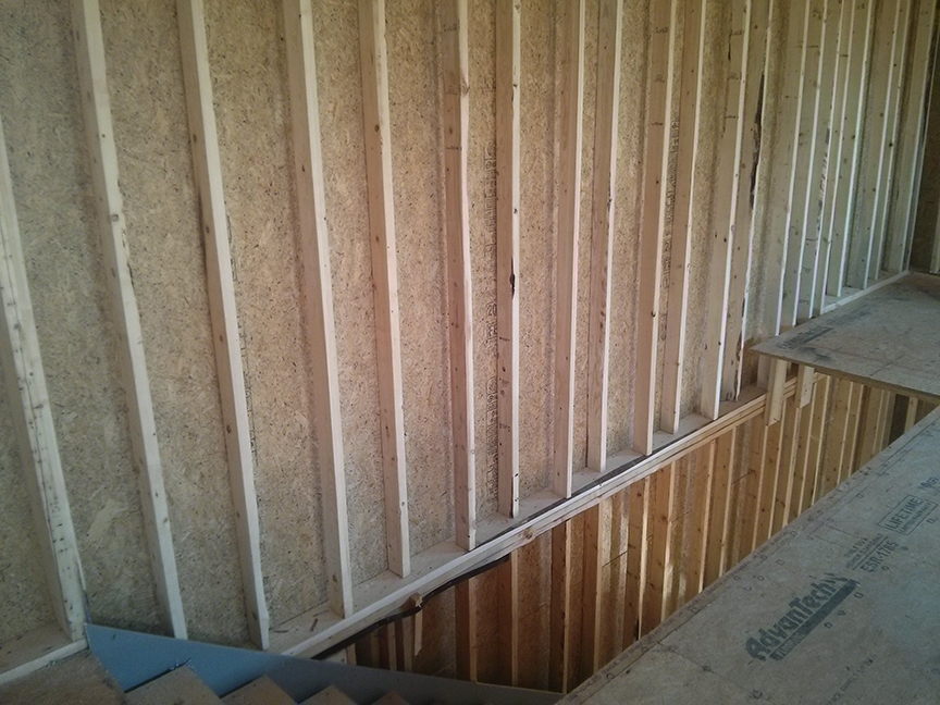
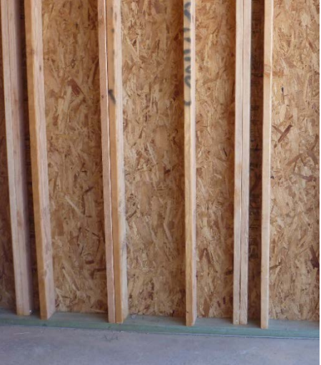
The 2x4 wall studs are staggered along the 2x6 sill plate providing space to weave insulation around each stud to stop thermal bridging through the wall.
Image
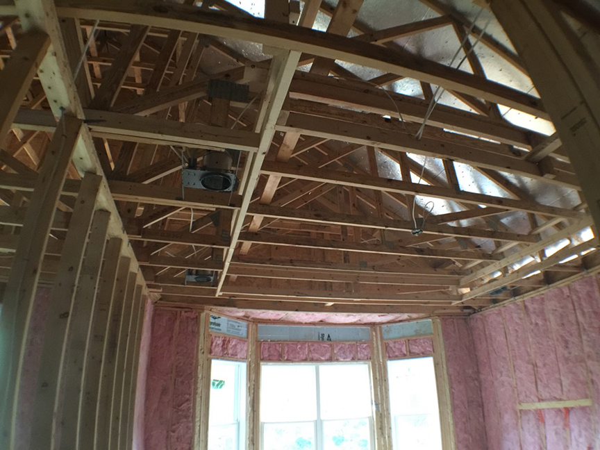
The advance-framed 2x6 24-inch on-center walls are covered with netting then filled with R-23 blown fiberglass.
Image
The builder staggers 2x4 studs on 2x6 top and bottom plates which provides gaps to fill in insulation around the framing for a continuous blanket of insulation.
Image
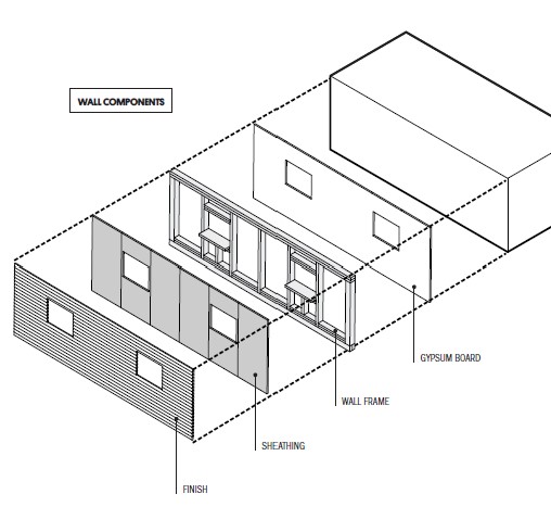
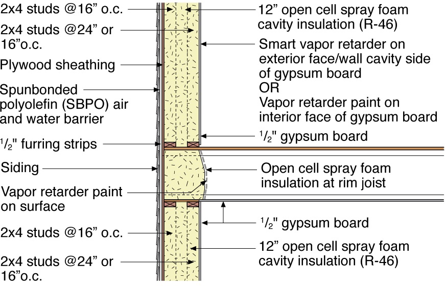
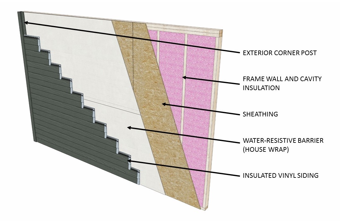
The components of a framed wall include from inside to out: gypsum, wood studs, OSB or plywood sheathing, and siding.
Image
The double walls form a 12-inch cavity that was sheathed with a coated OSB then coated with 3 inches of closed-cell spray foam; they will be filled with 9 inches of blown fiberglass.
Image
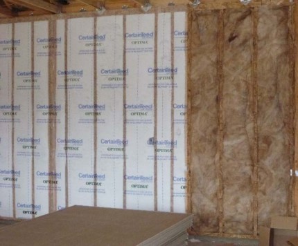
The energy-saving double wall construction uses two side-by-side stud walls, providing an extra-thick wall cavity that can be filled with more than twice as much insulation as a 2x6 wall.
Image
The exterior walls are double walls consisting of two 2x4 stud walls set 3 inches apart to form a 10-inch-thick wall cavity that is filled with blown-in fiberglass to provide a continuous R-40 blanket of insulation around the home.
Image
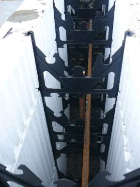
The ICF consists of foam forms that are held in place with plastic or metal spacers and reinforced with metal rebar
Image
Image
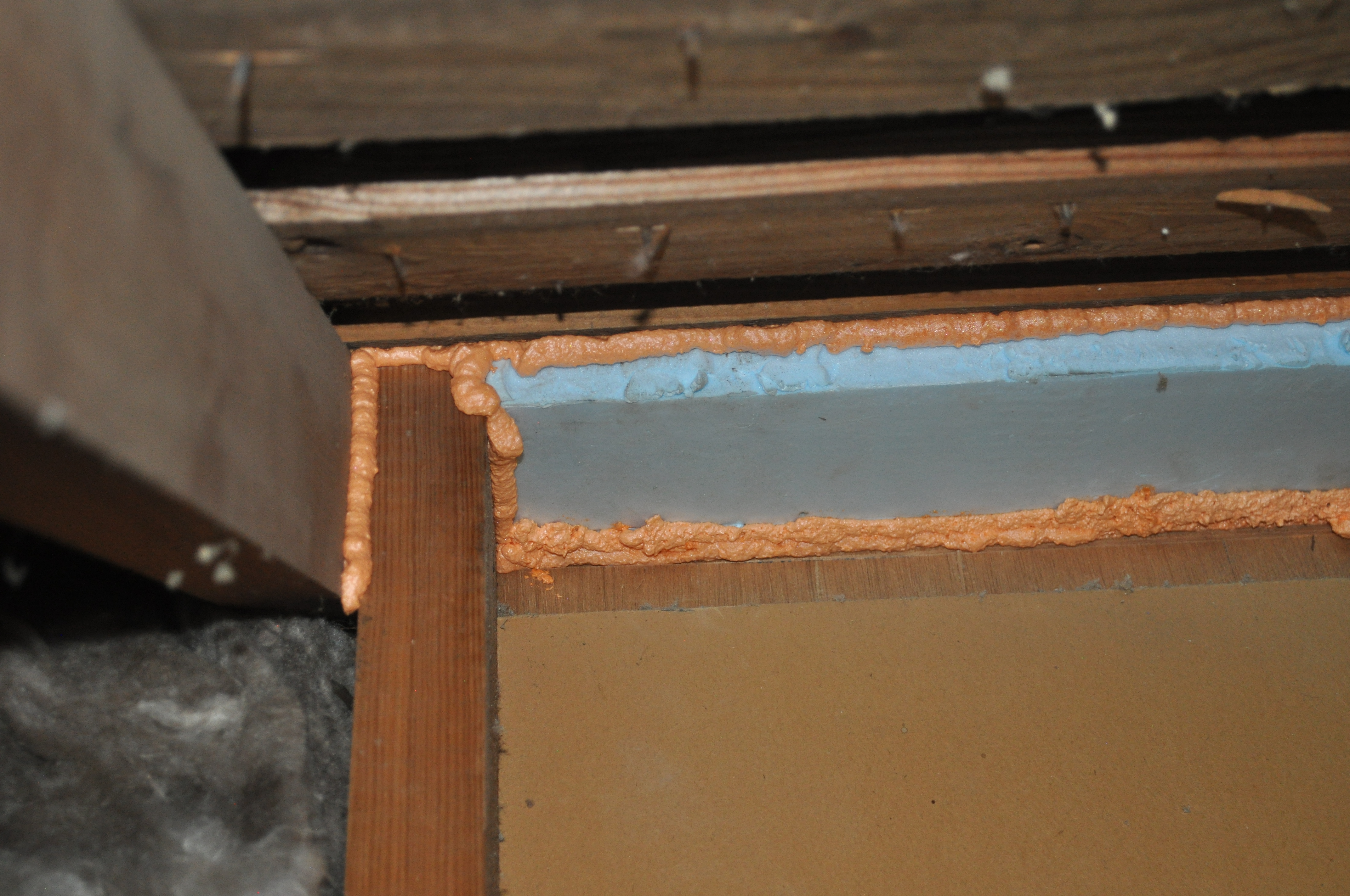
The missing top plate in a kneewall was covered with lumber and rigid foam insulation and then sealed with spray foam
Image
The OSB roof decking product comes with an adhered radiant foil barrier which helps to prevent heat transfer in or out of the vented attic, while R-13 unfaced fiberglass fills the advanced-framed 2x6 walls.
Image
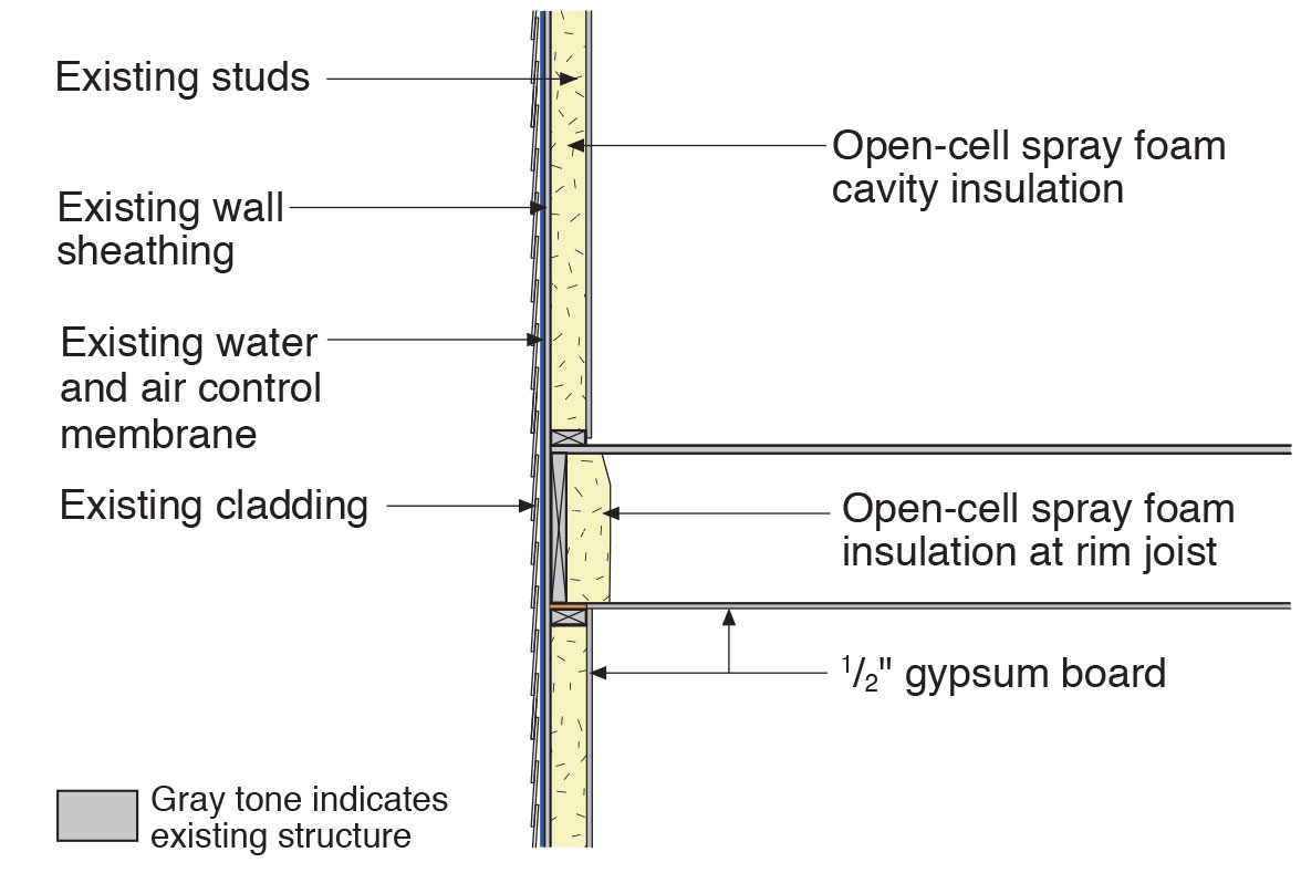
The rim joists and top plates are air sealed and insulated with open-cell spray foam while the walls are filled with blown fiberglass.
Image
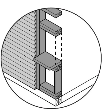
Thermal bridging is eliminated at the rim joist with the use of joist ledgers that are anchored in the wall
Image
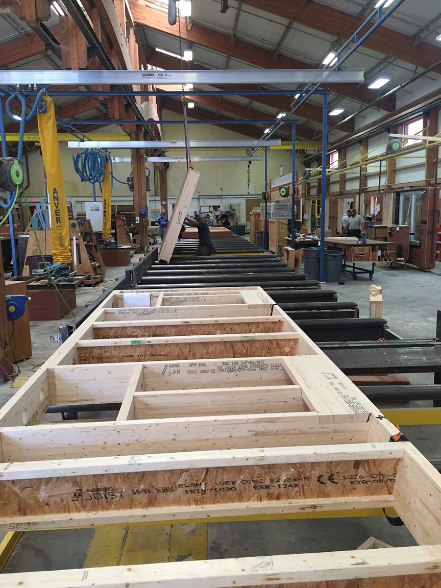
These factory-built walls consist of 9.5-inch I-studs sheathed with coated OSB, faced with OSB, and dense-packed with cellulose; a second interior surface of drywall is added to provide a 1.5-inch cavity for electrical wiring.
Image
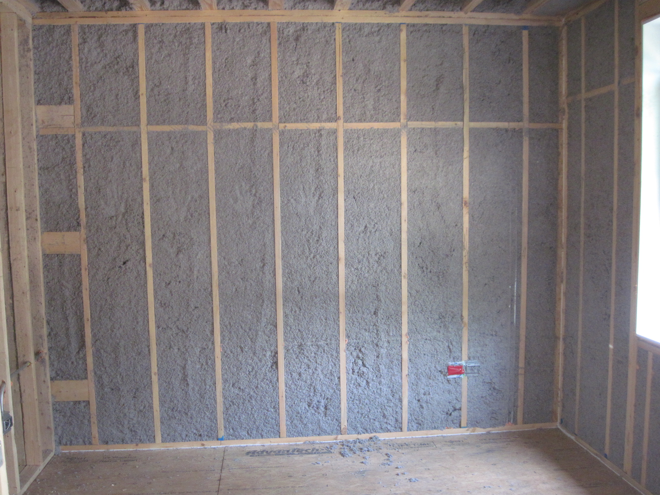
This 2x6 wall is advanced framed and filled with dense-packed cellulose insulation.
Image
This home’s double-wall construction provides a 9-inch wall cavity for insulation.
Image
This hot climate zone home uses high quality batt insulation between studs to insulate this connecting garage wall.
Image
This hot climate zone home uses high quality batt insulation to insulate truss-joist headers.
Image
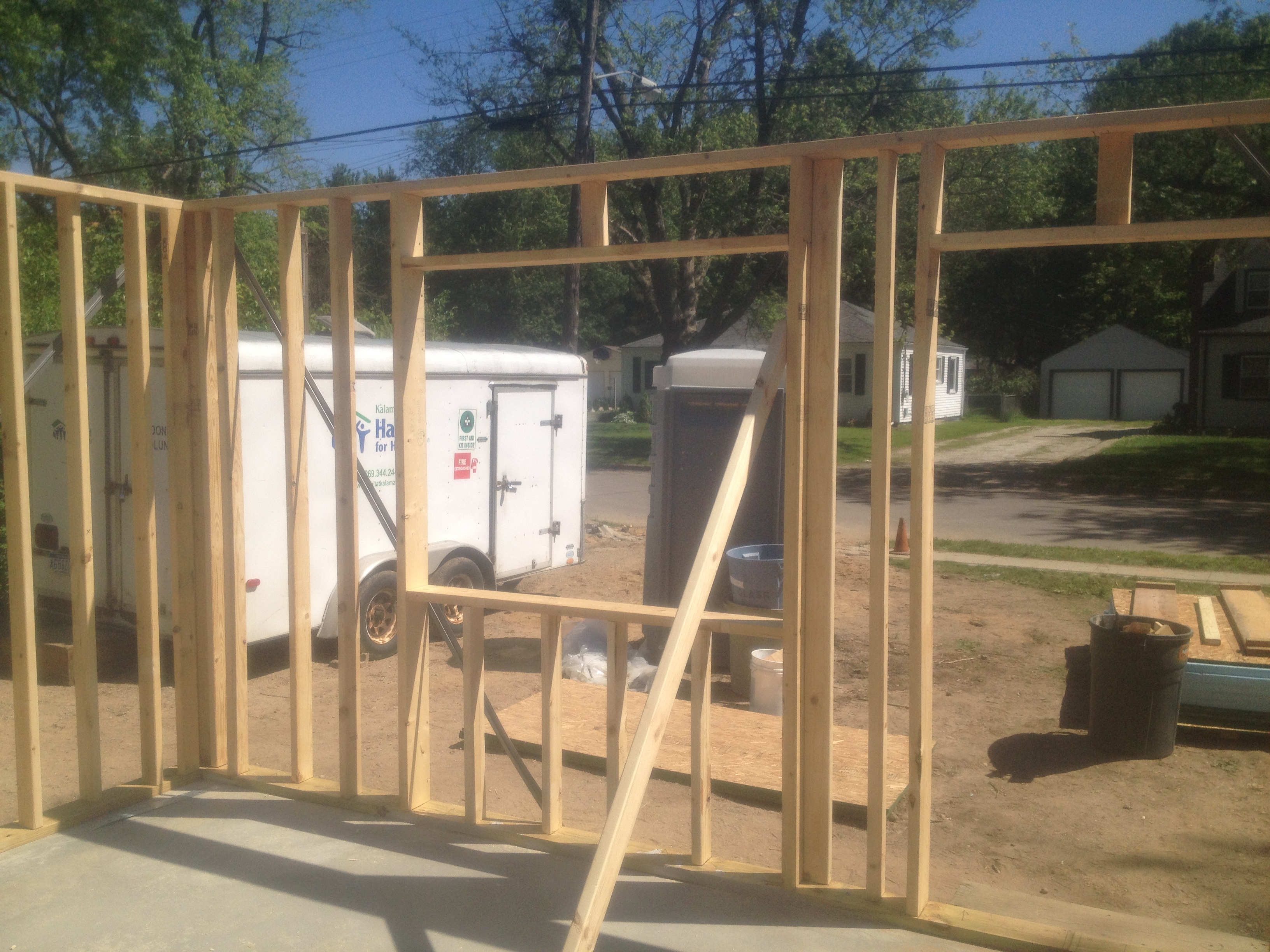
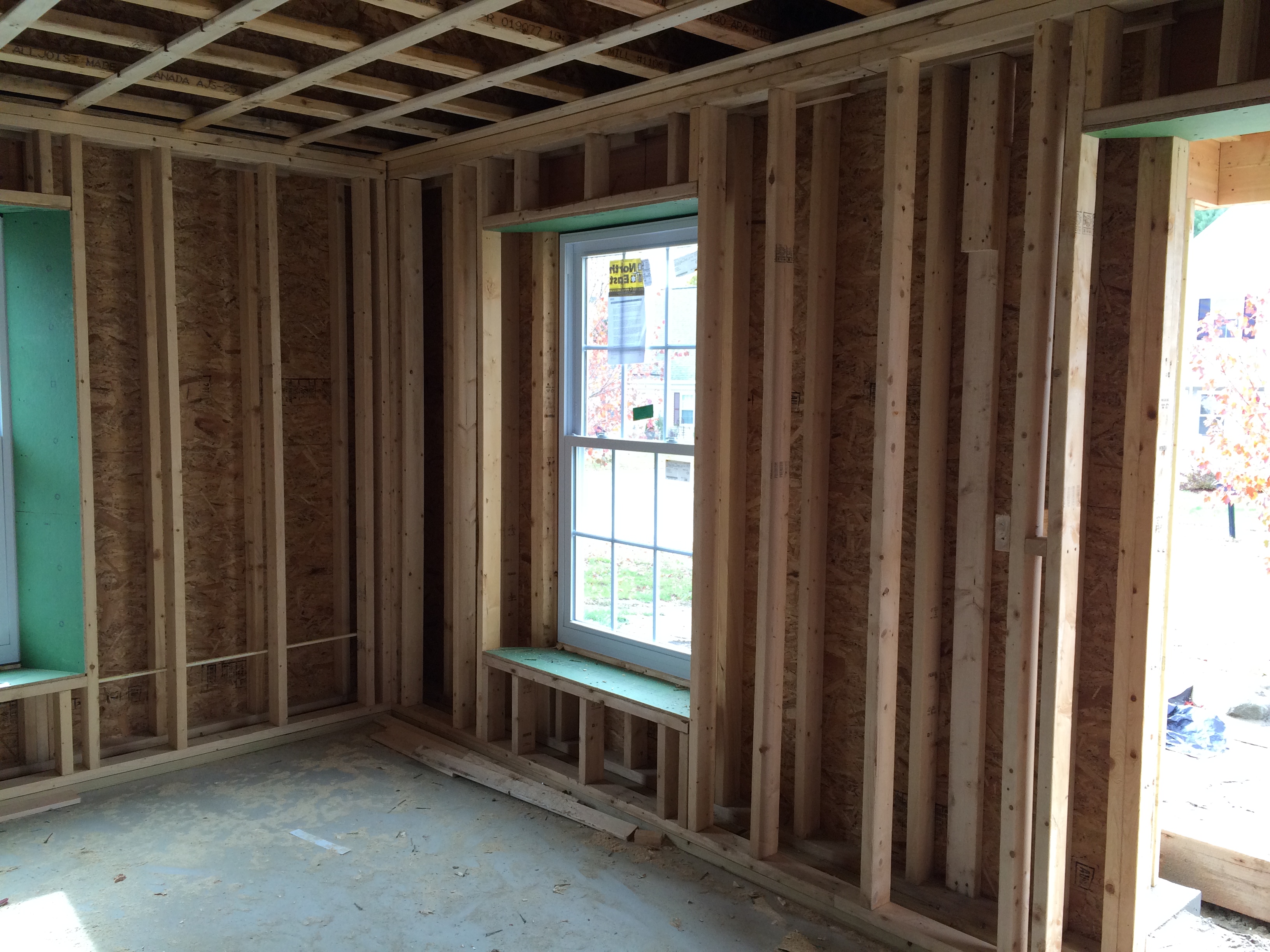
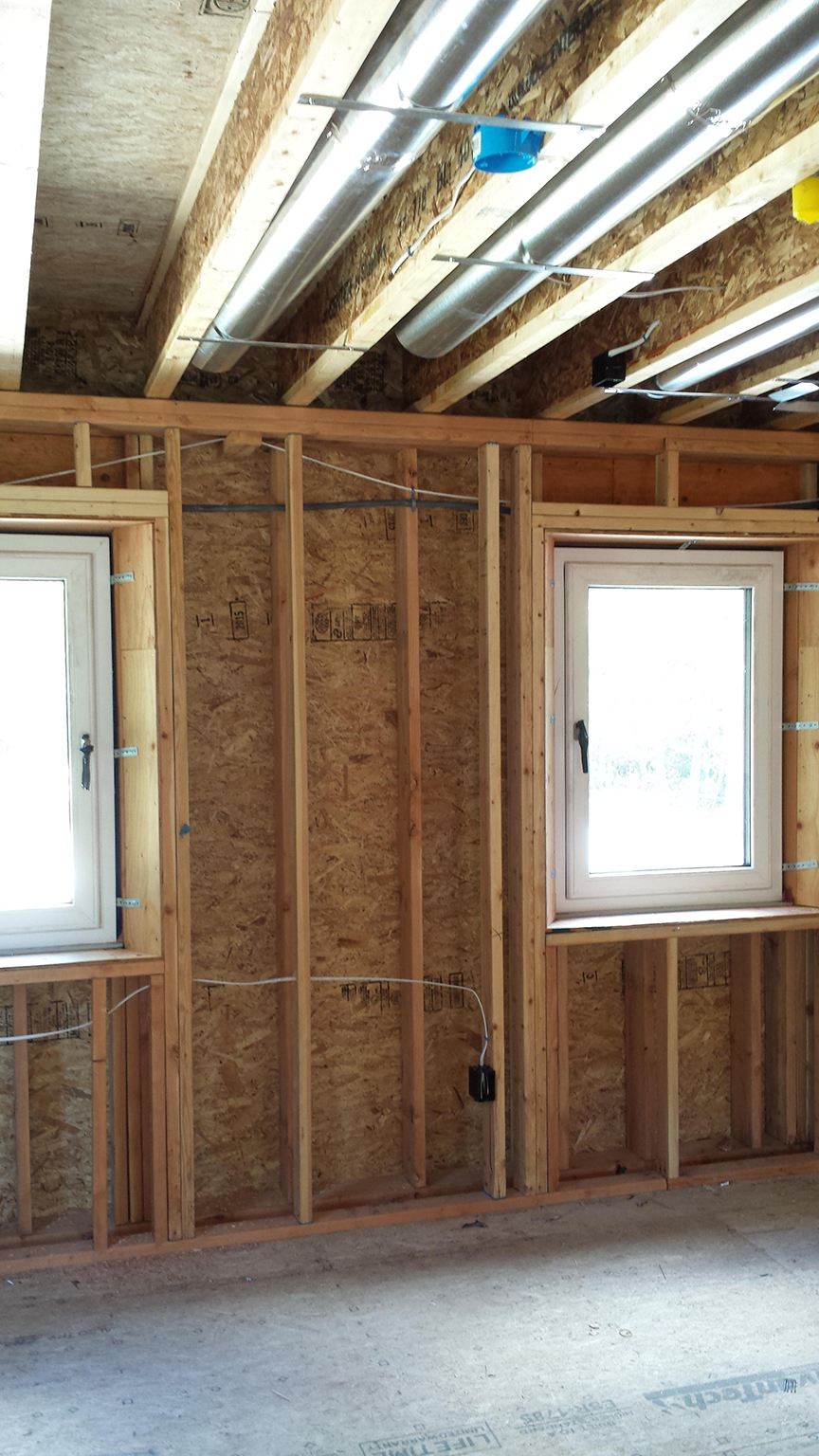
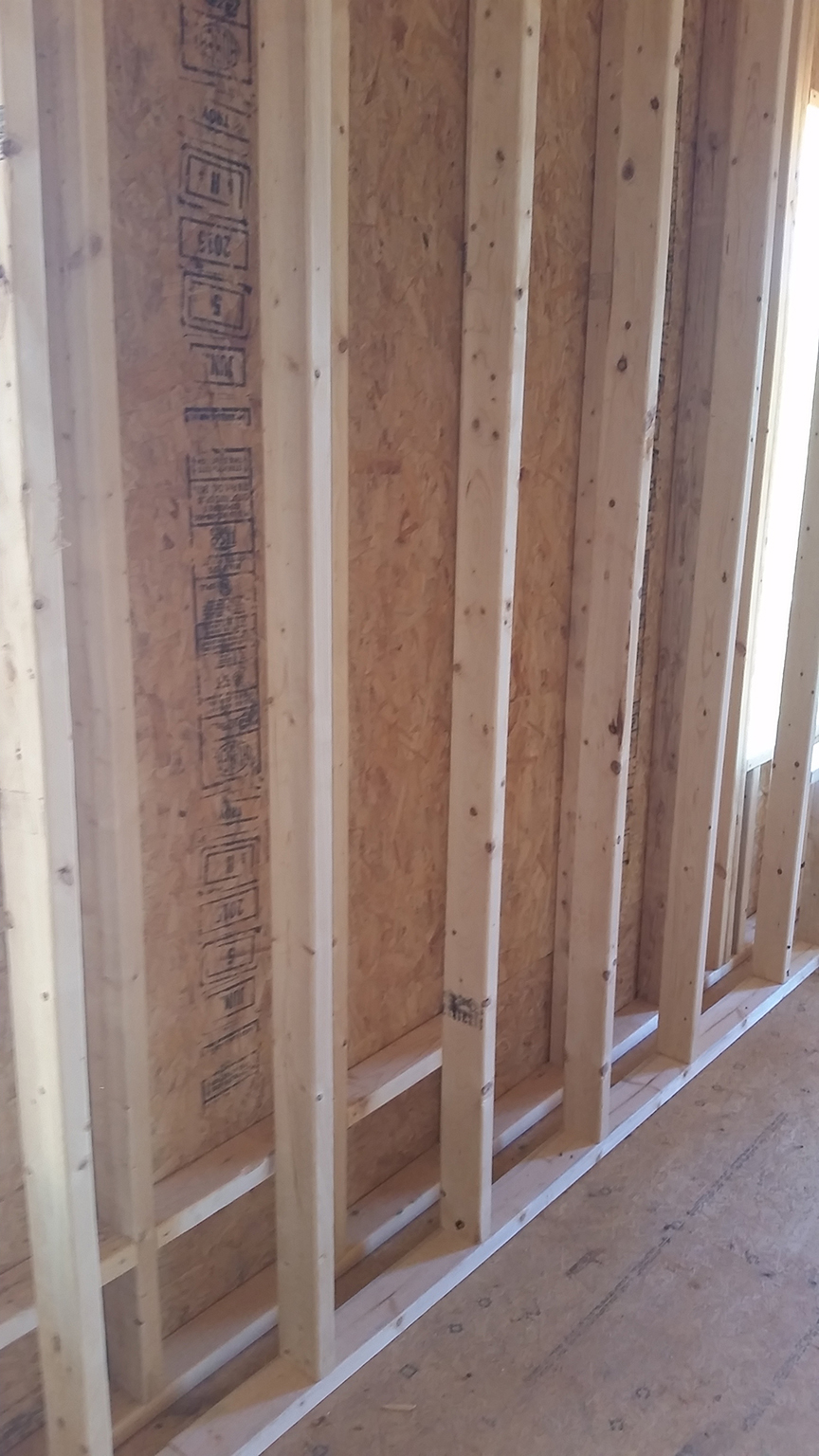
This house is being built with advanced framing techniques including 2x6 24-inch on-center wall framing
Image
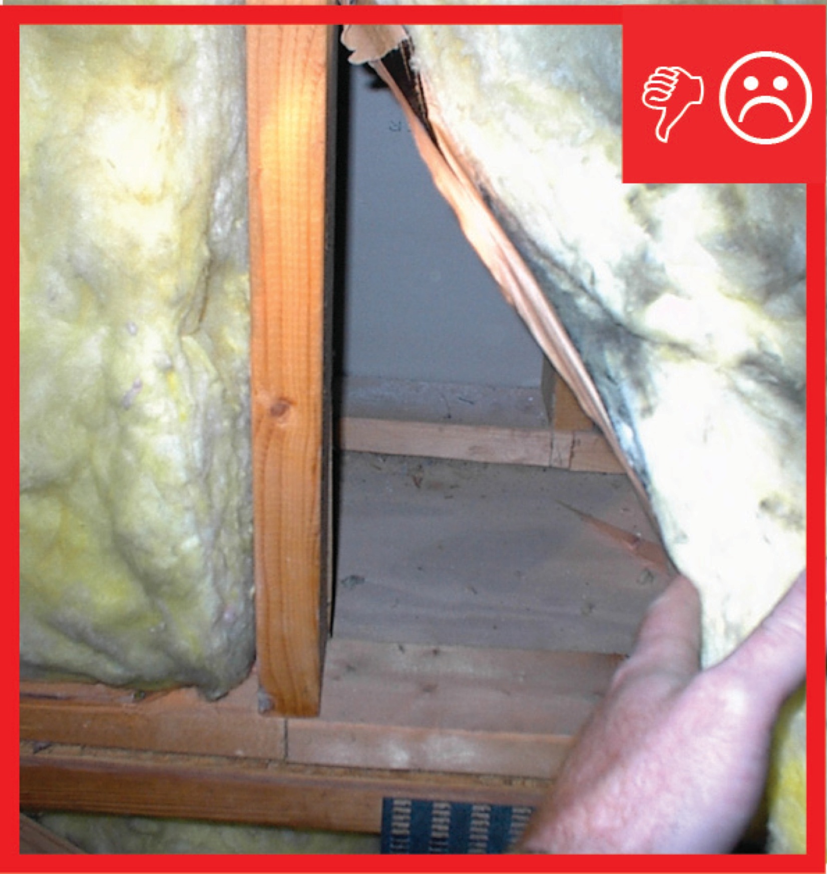
This kneewall has no top plate and the resulting gap provides a wide-open pathway for air and vapor to travel between the living space and the attic
Image
This wood-framed wall is connected with framing anchors, metal strapping and ties, and anchor bolts to secure the roof to the walls and walls to the foundation
Image
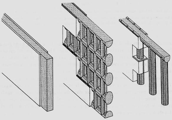
Three common ICF wall systems: the flat wall, the waffle wall, and the post-and-beam wall
Image
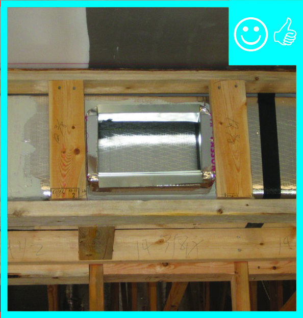
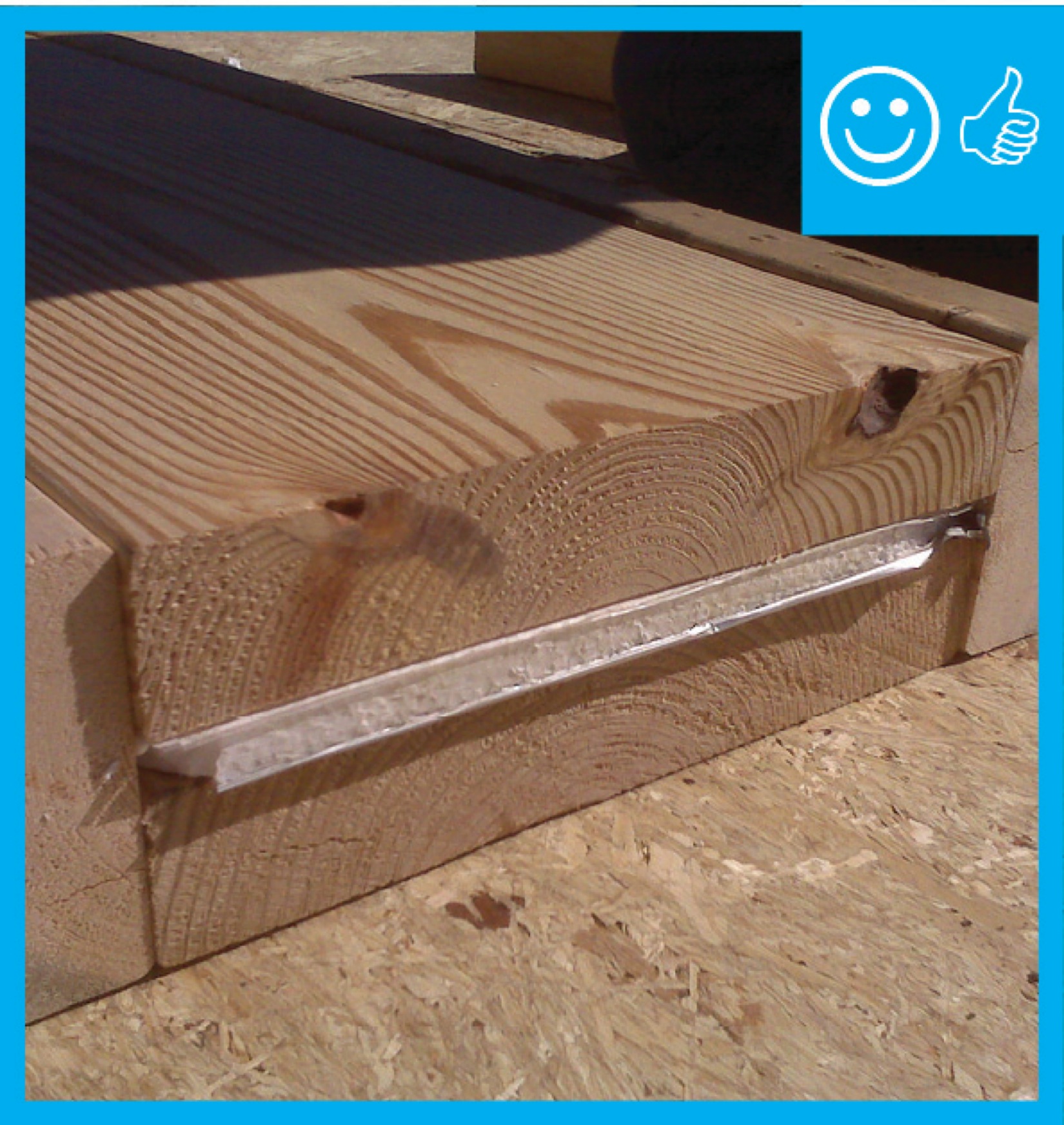
To keep chase width to a minimum, use flat sheet metal as opposed to a collar and flex duct for supplies into rooms where the chase is located
Image
Image
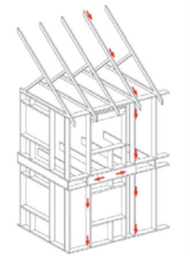
Uplift forces acting on the roof are met with roof-wall connections that distribute the forces down the walls and into the foundation along the continuous load path.
Image
Use a truss joist header assembly as shown here to reduce thermal bridging in hot climate zones.
Image
Image
Image
Image
Image
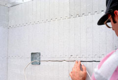
Utilities are commonly recessed into cutouts in the foam after concrete has been poured
Image

Image
Window and door rough openings in the ICF wall are surrounded with pressure-treated wood
Image
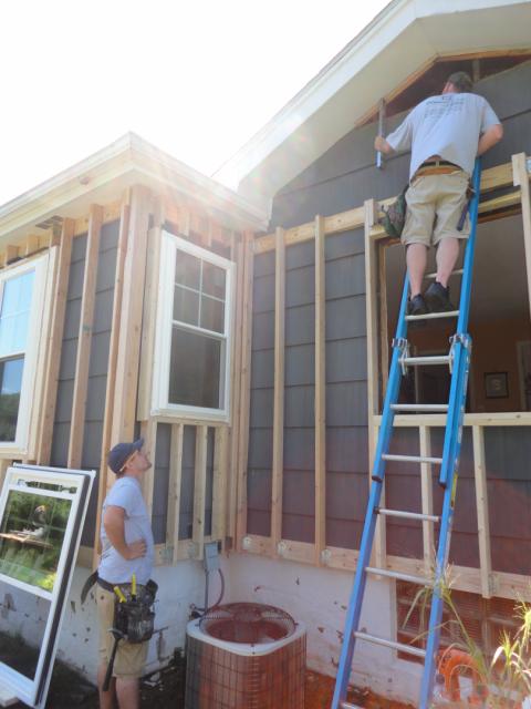
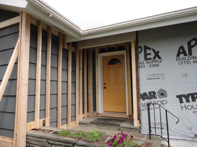
Windows are installed in new framing in preparation for adding exterior spray foam insulation
Image

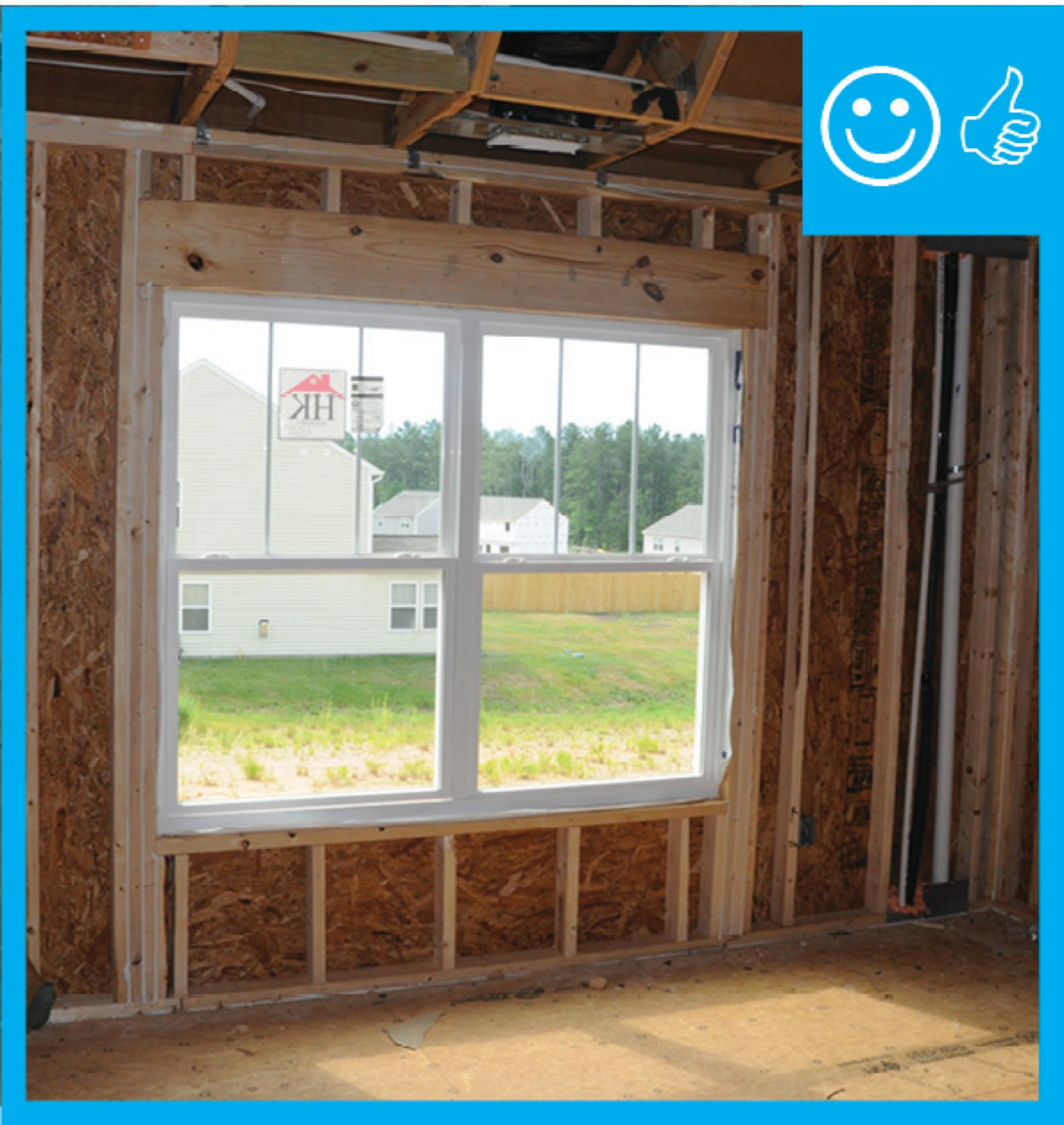
Windows are sized and positioned so only one king stud is needed on each side of the window.
Image

Image

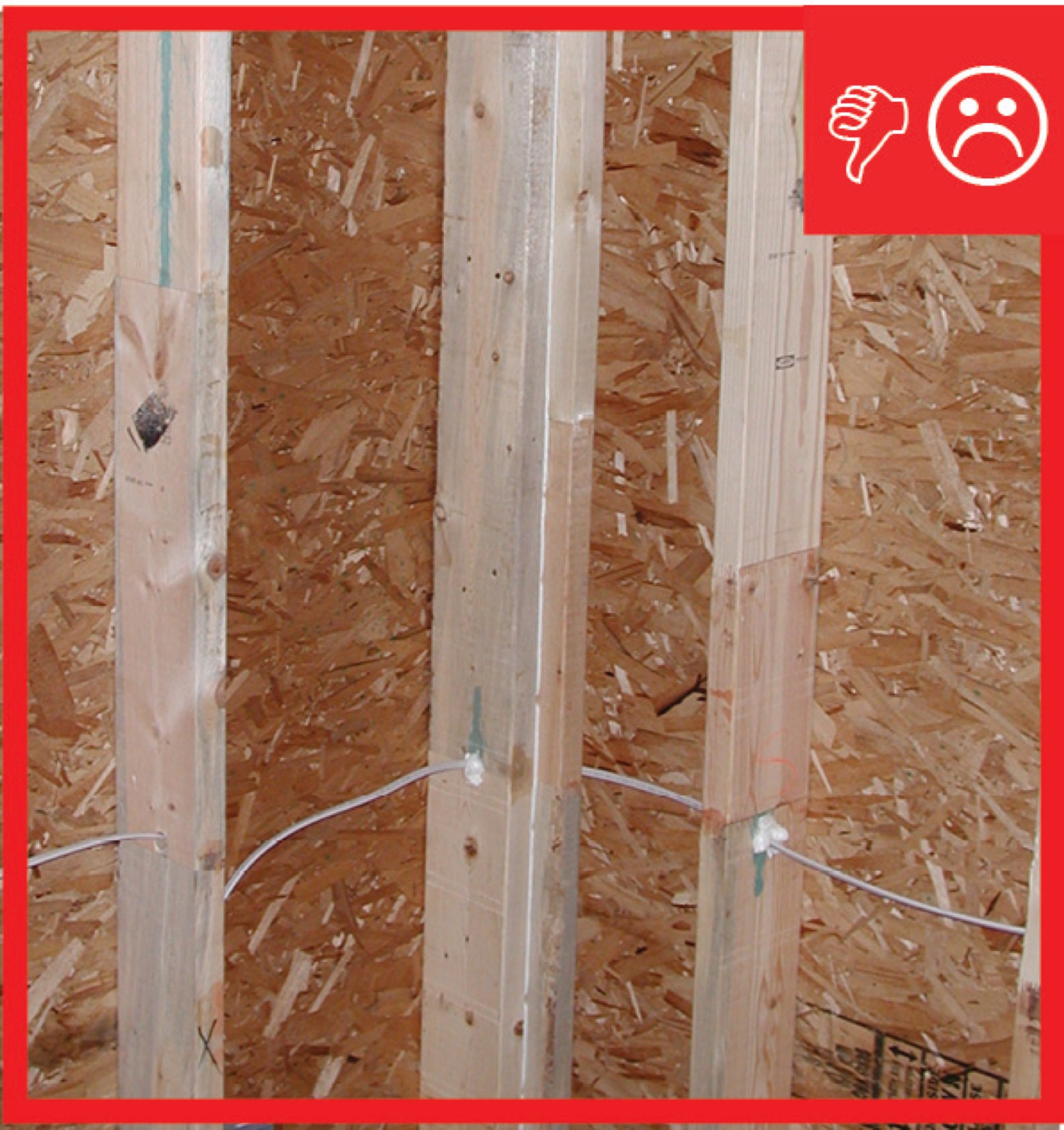
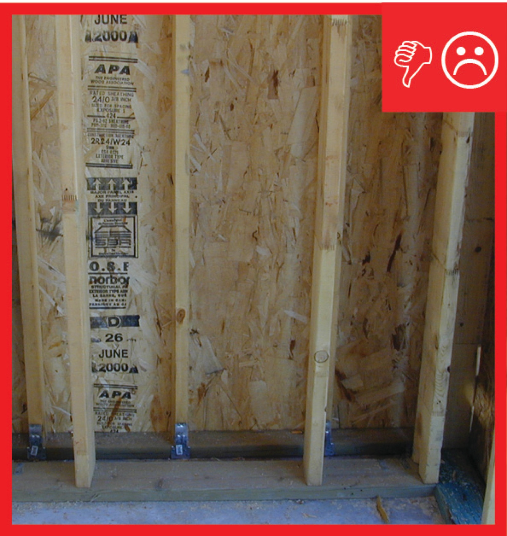
Wrong - Board is not properly cut and is split where it is toenailed into top plate.
Image

Image
Image
Image
Wrong - Framing a dormer using only toe nailing and end nailing is not acceptable in areas subjected to high winds, hurricanes, or earthquakes.
Image
Image
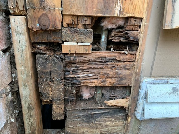
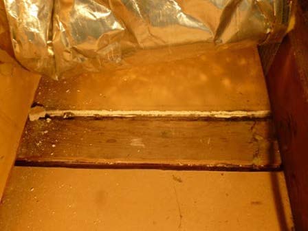
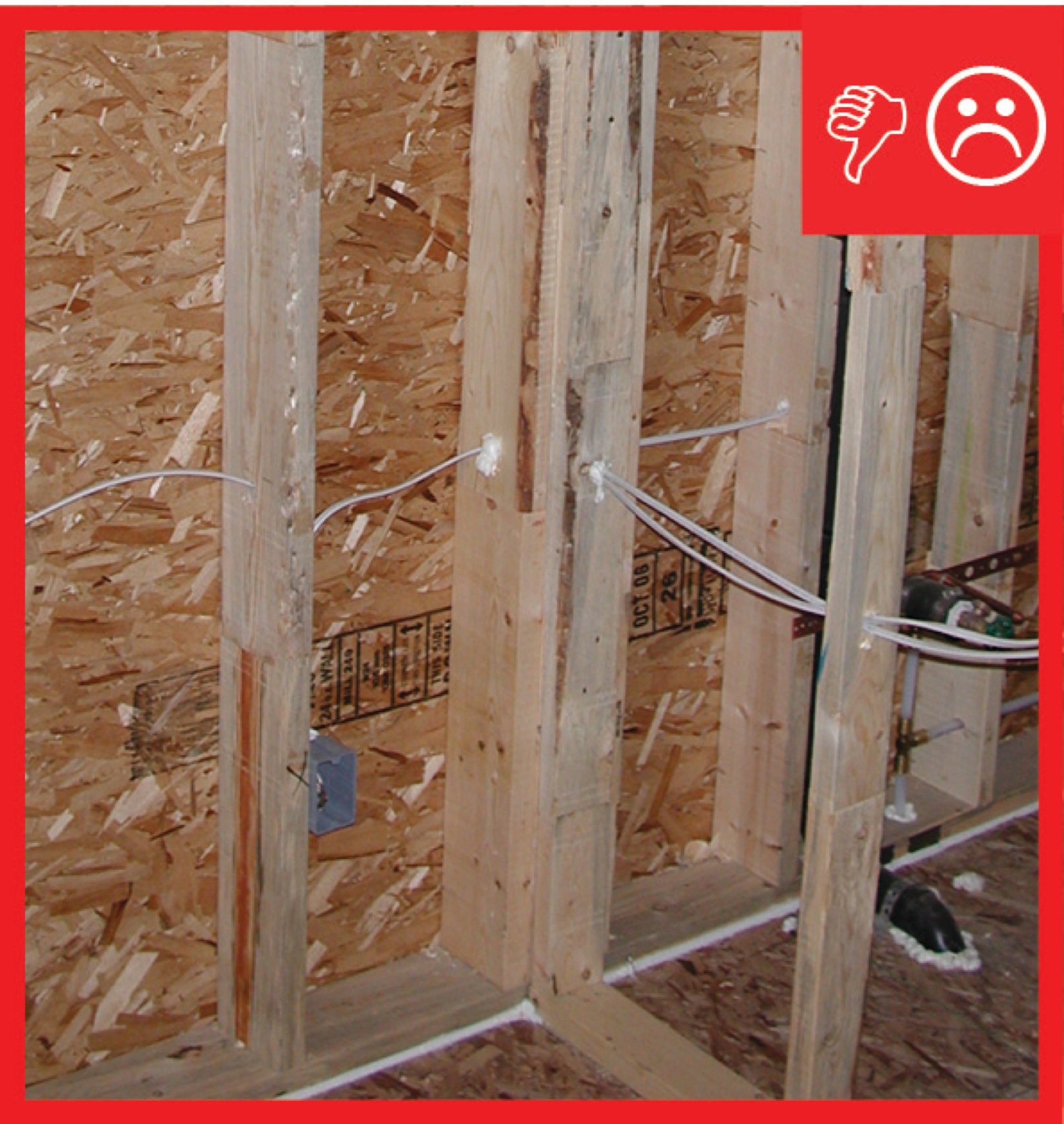
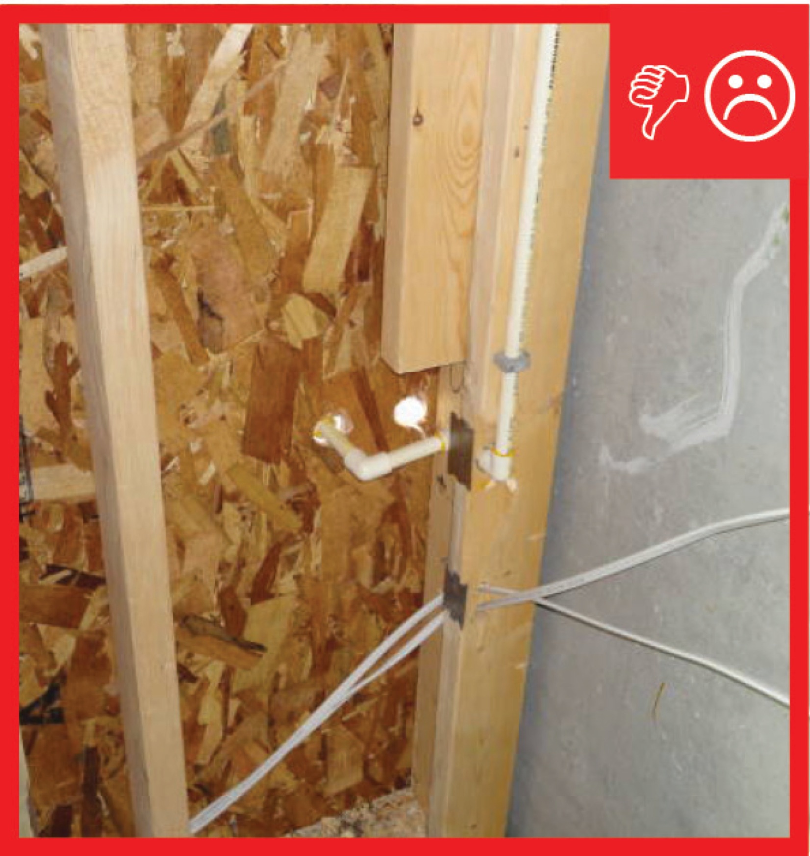
Wrong - Lack of a weather-resistant barrier allowed water to get behind the siding and rot the framing in this corner rim joist area.
Image

Image

Wrong - The studs added for support were cut at an angle providing weak support where the stud meets the compression block.
Image
Image
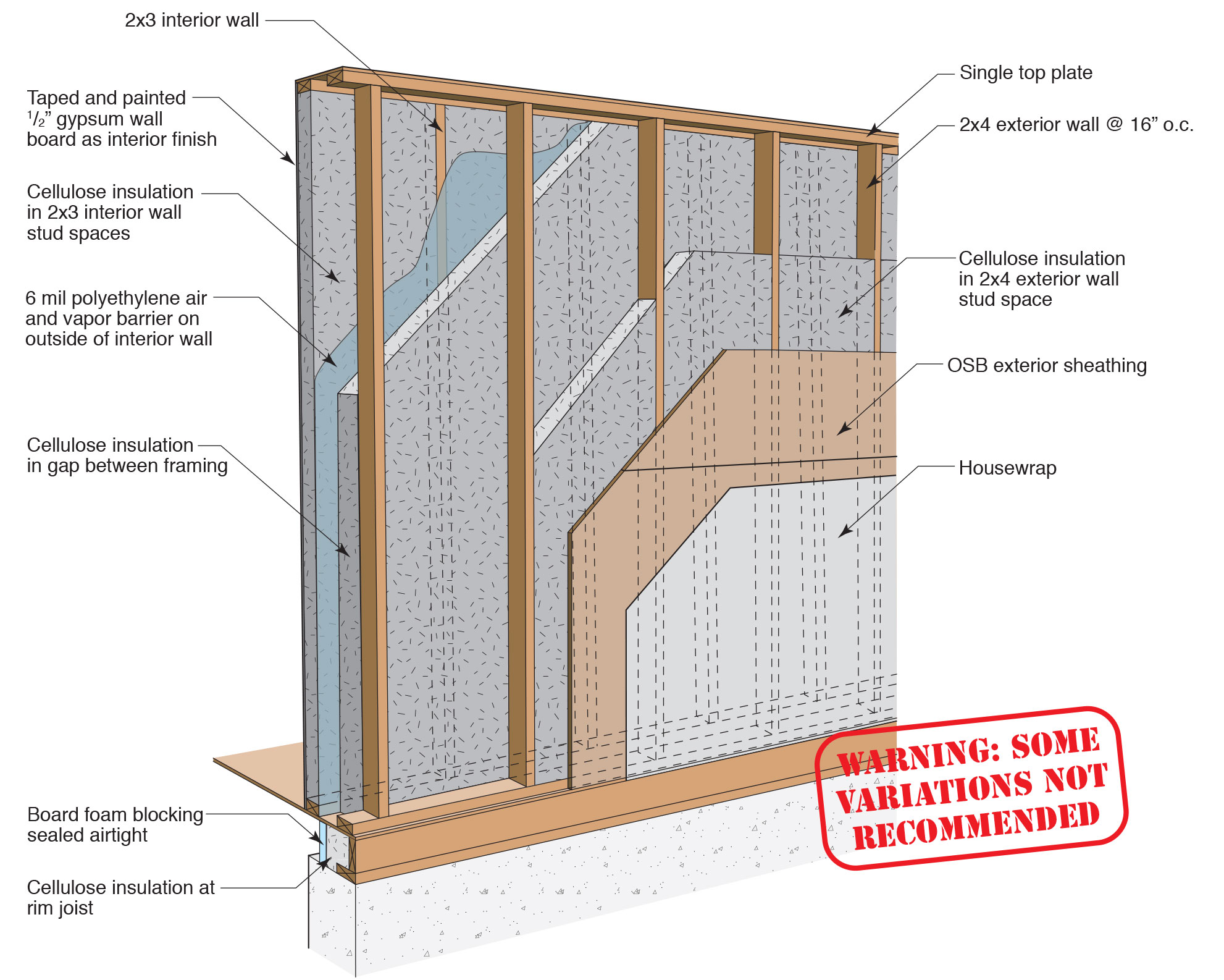
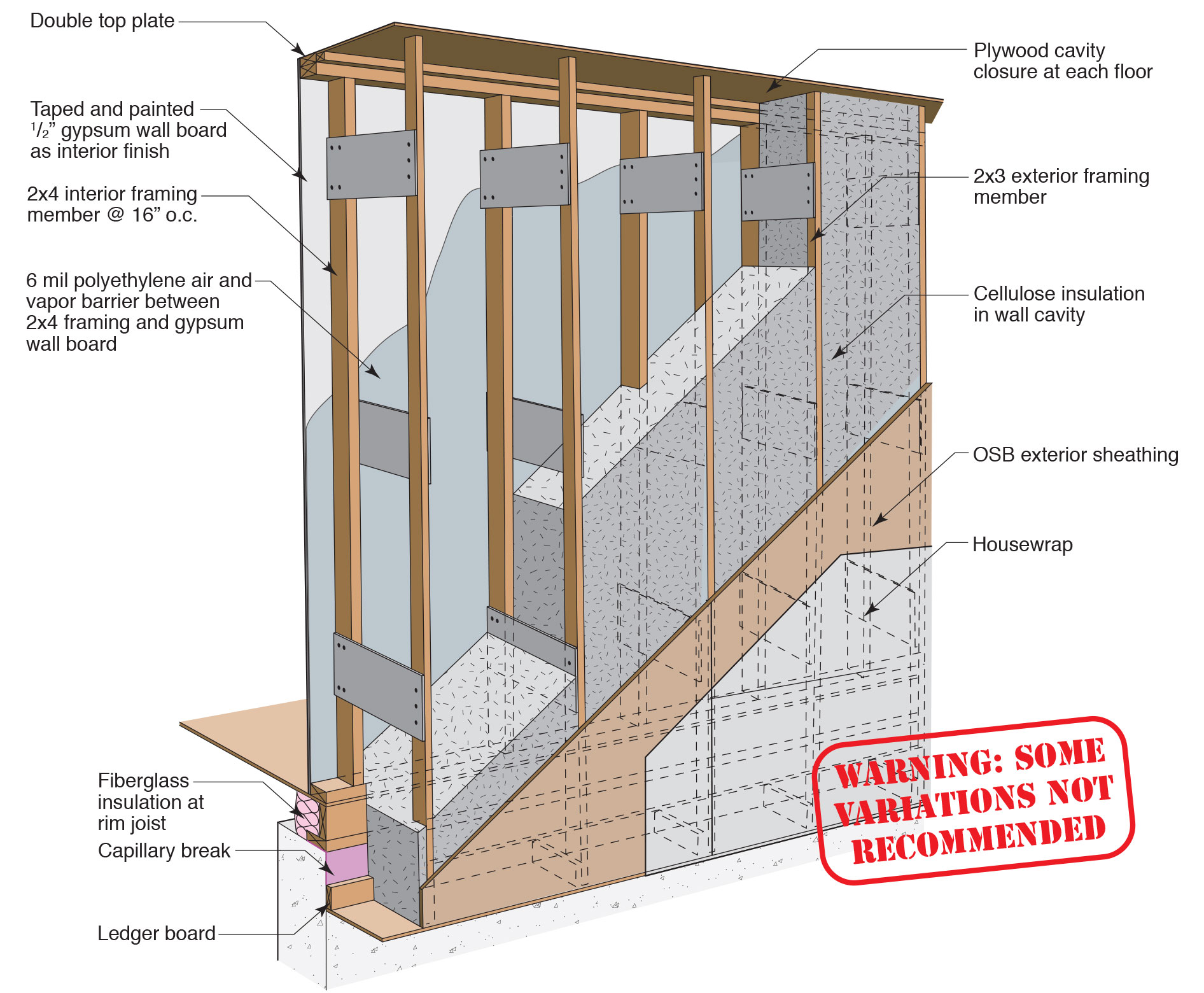
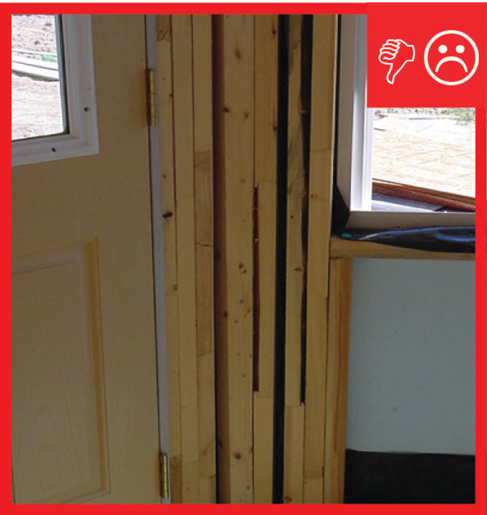
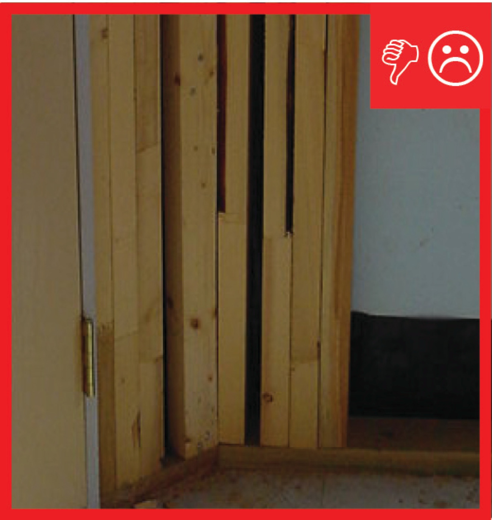
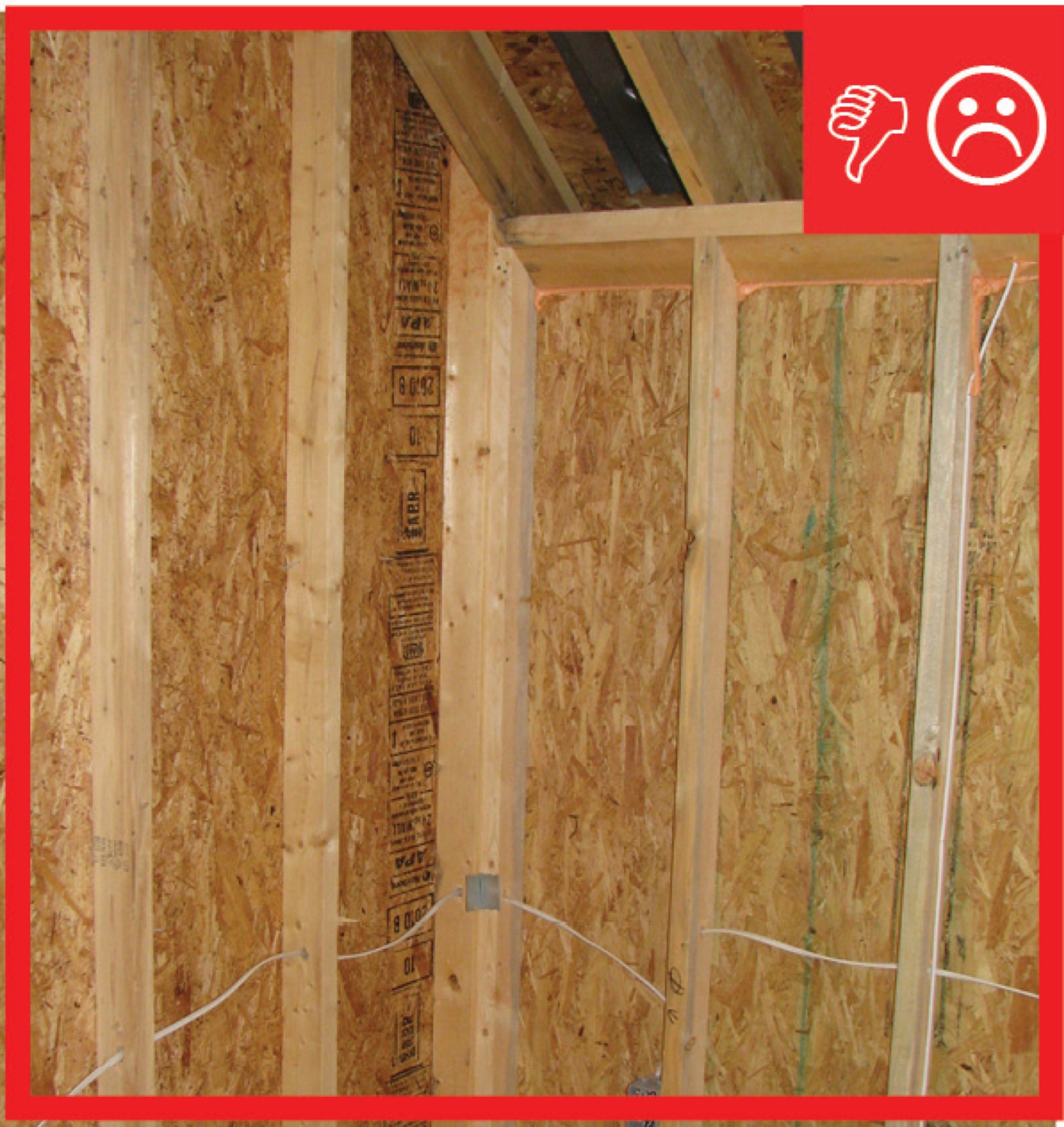
Wrong – Conventional T-post detail is extremely difficult to insulate and usually doesn't happen
Image
Image

Image
Image
Image
Image
Image
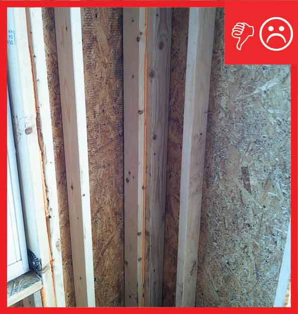
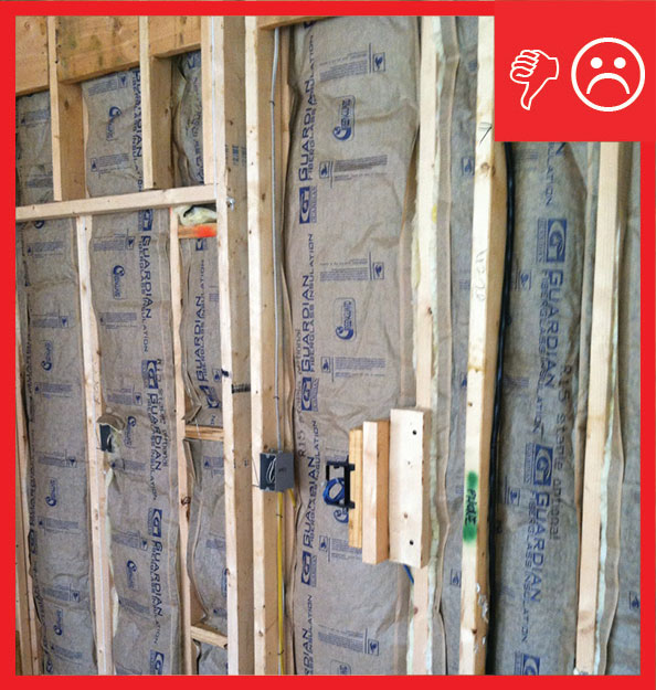
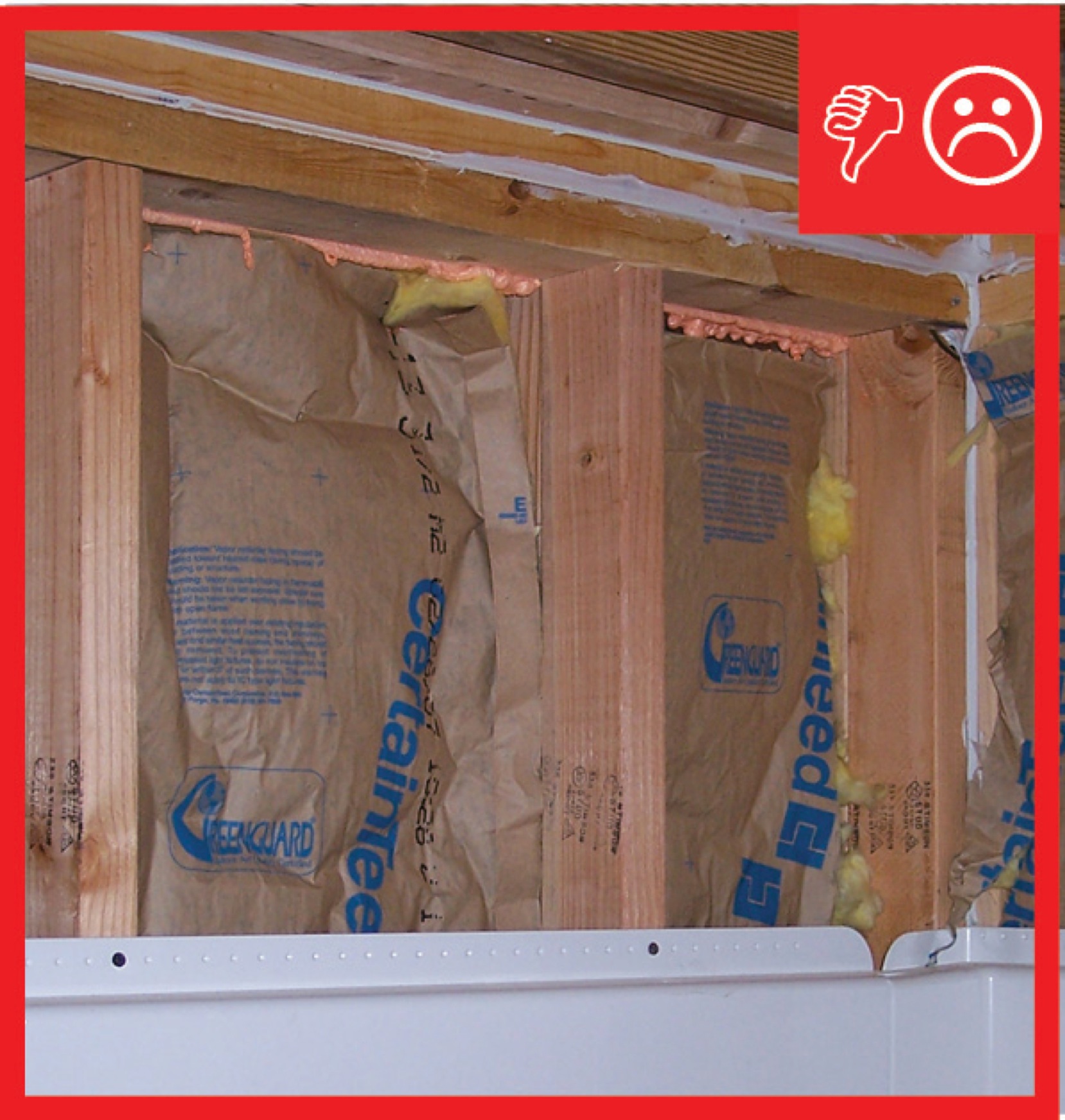
Wrong – Insulation does not fill entire cavity nor is there an air barrier present between the double wall
Image
Image
Wrong – No air barrier installed between the walls and a larger gap between the walls that needs sealing
Image
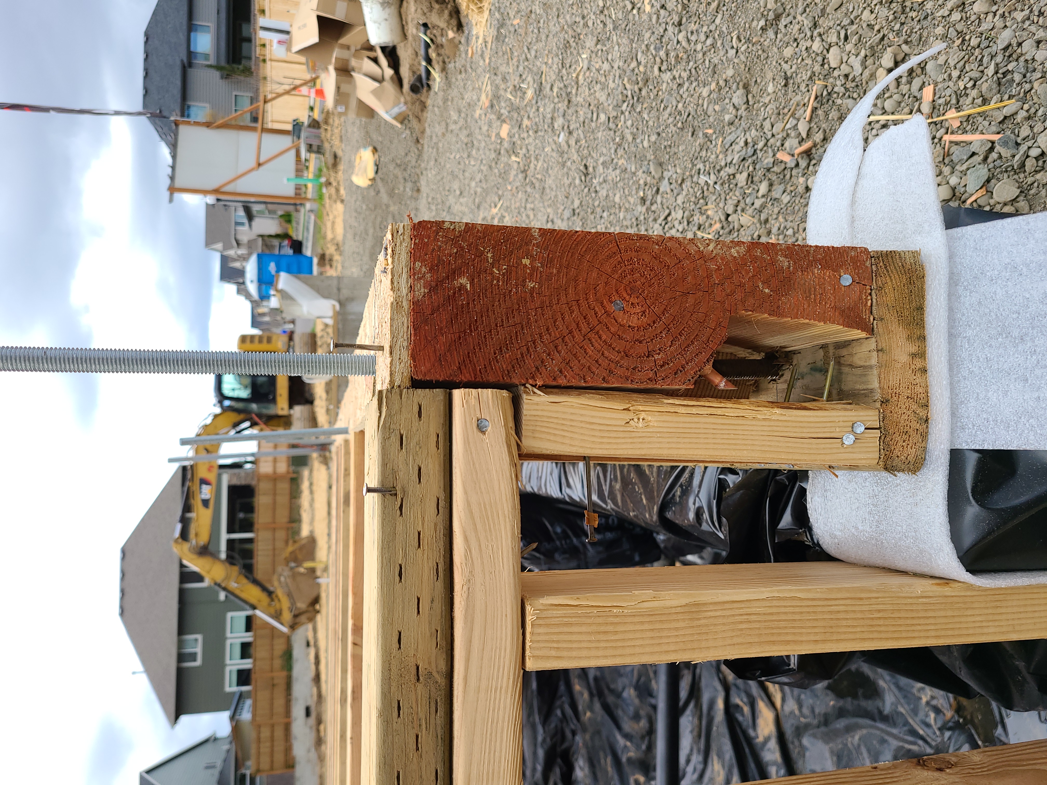
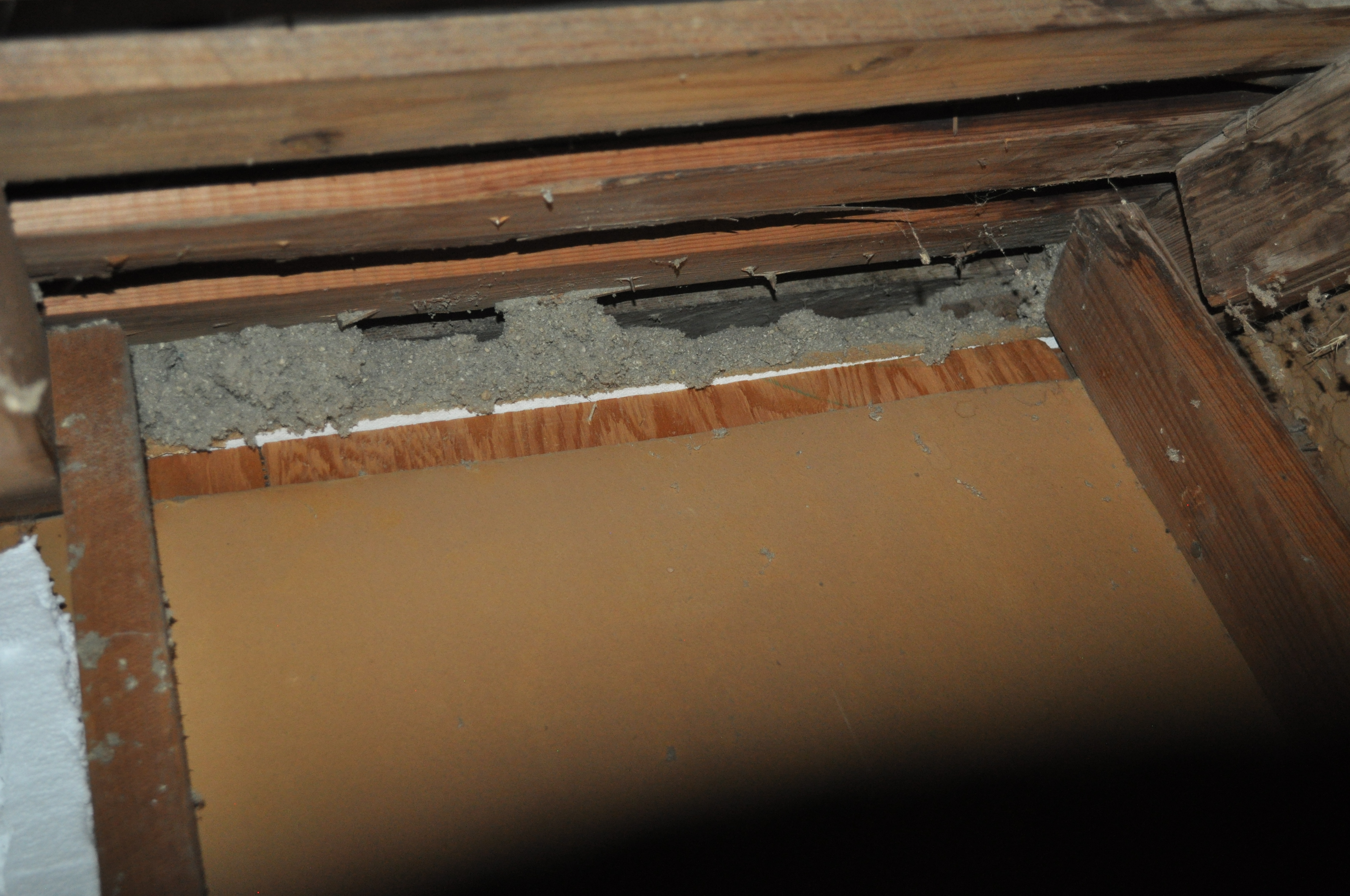
Wrong – The damaged rim joist was not replaced and its strength is compromised in a critical load-bearing corner.
Image

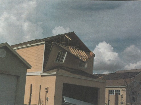
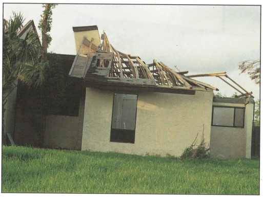
Wrong – The roof sheathing was inadequately fastened and gave way causing the gable end wall to fail
Image
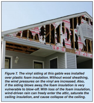
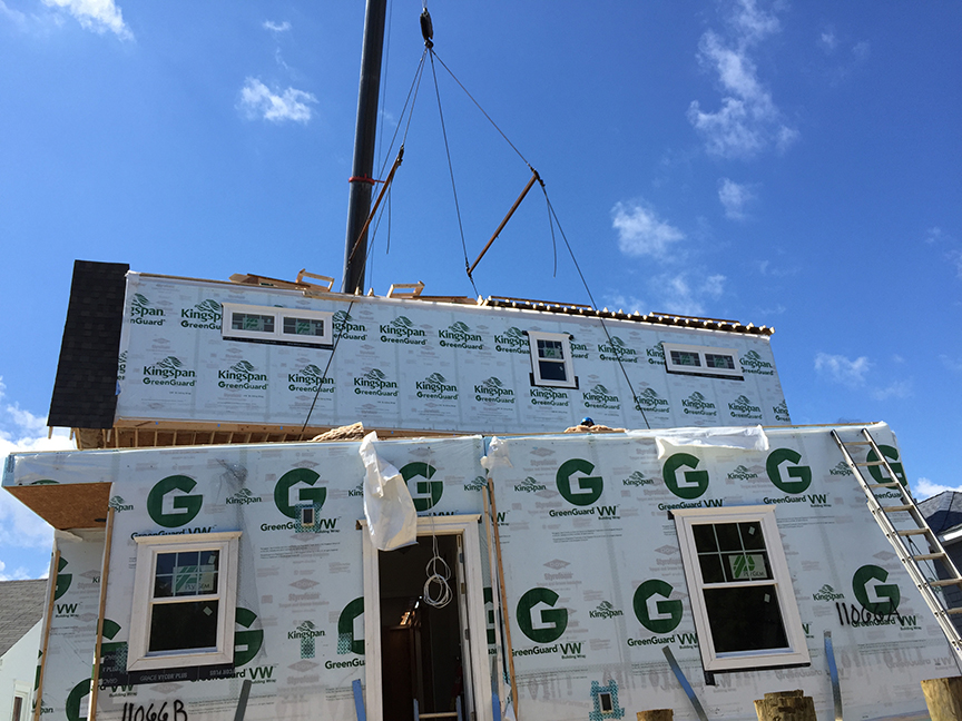
Wrong – The vinyl siding at this gable was installed over plastic foam insulation
Image
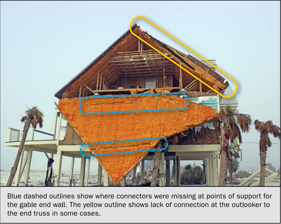
Wrong – This gable end wall failed because connectors were missing at points of support (blue circles) and the outlookers were not connected to the end truss (yellow circle)
Image
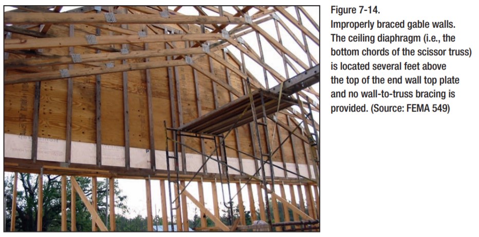
Wrong – This house under construction is lacking wall to truss bracing and the bottom chord of the scissor trusses is several feet above the top of the end wall top plate
Image
Image

Image
Image
Image
Image
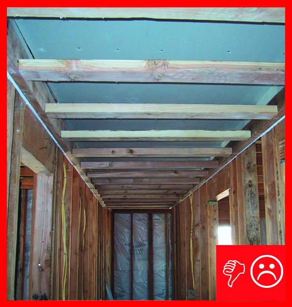
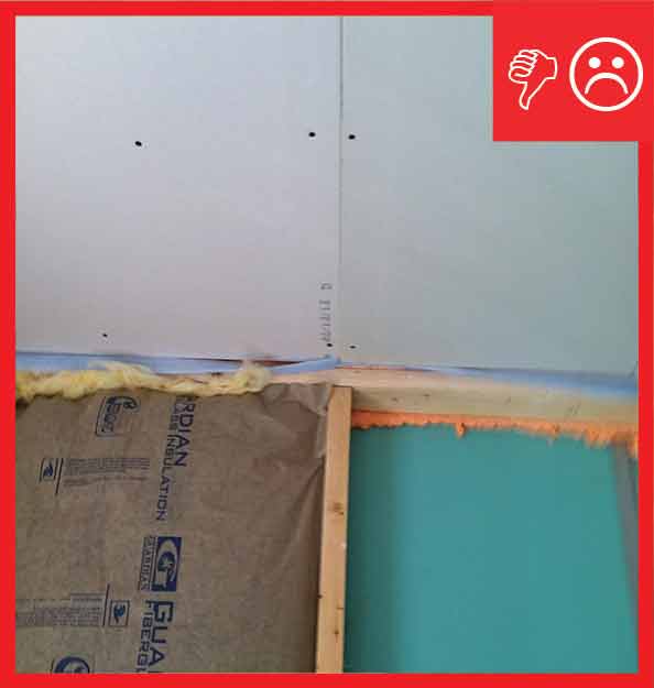
Wrong: Drywall does not extend beyond chase wall framing and is unsealed in a hallway dropped ceiling chase
Image
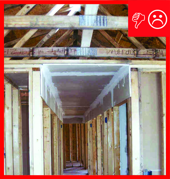
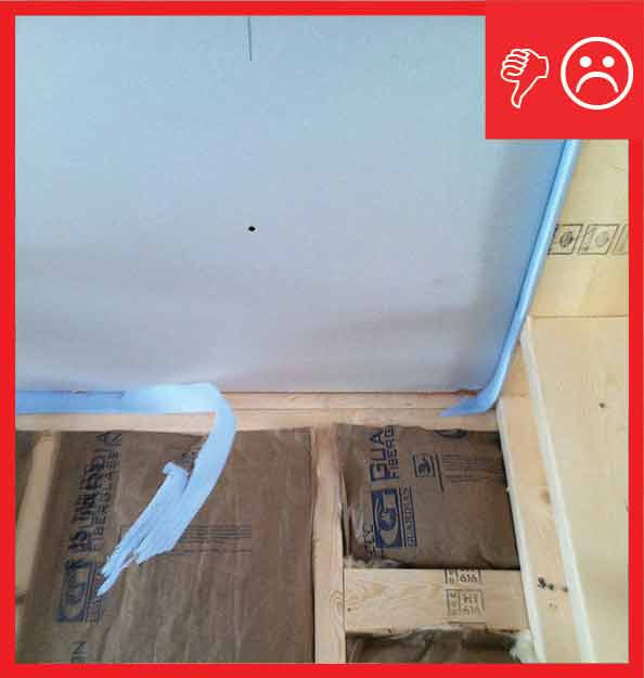
Wrong: Drywall does not extend beyond the top plate of the interior walls. This installation has the potential for leakage at the sides where the ducts penetrate the side walls of the chase