Showing results 1 - 63 of 63
Image
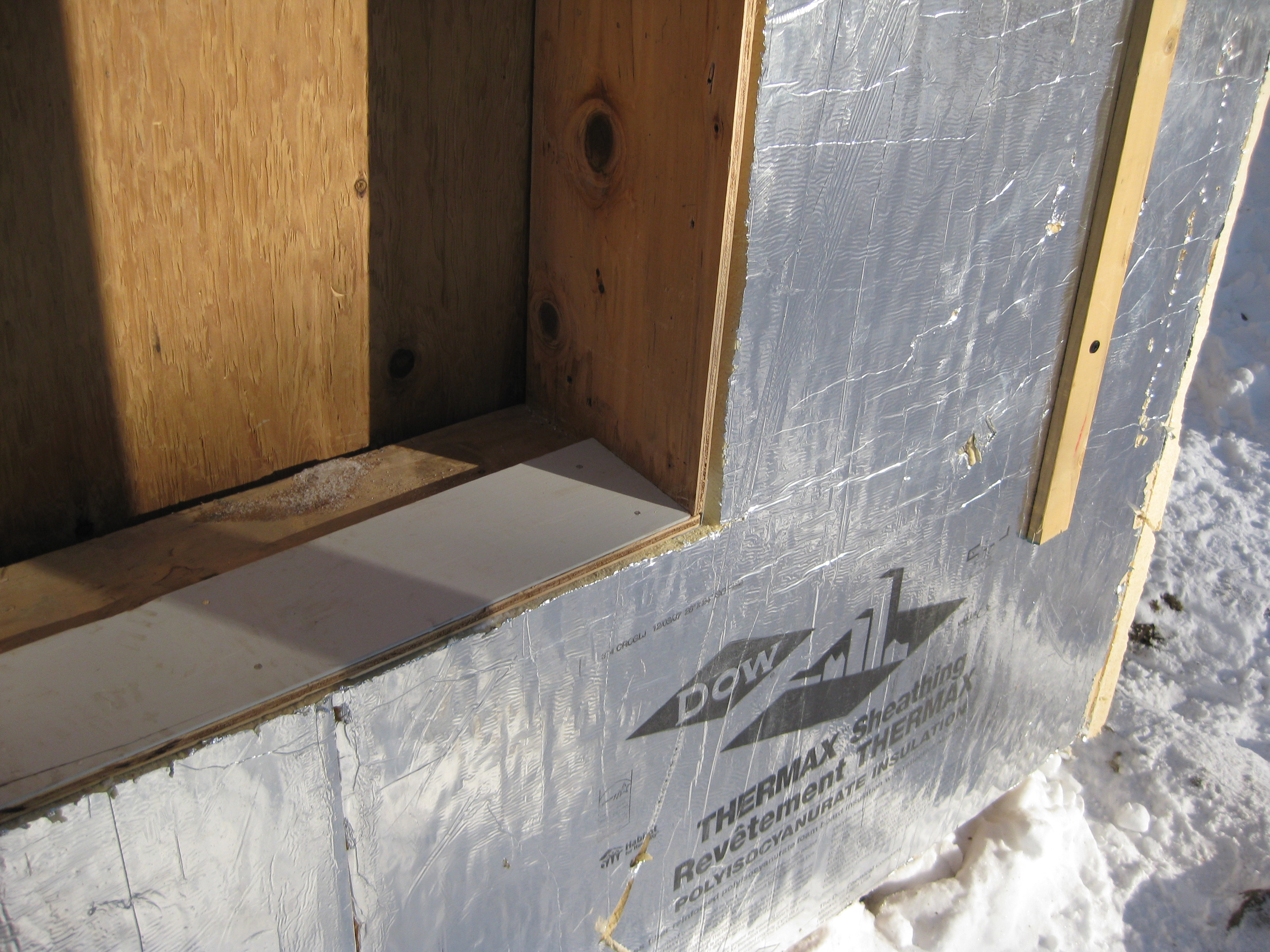
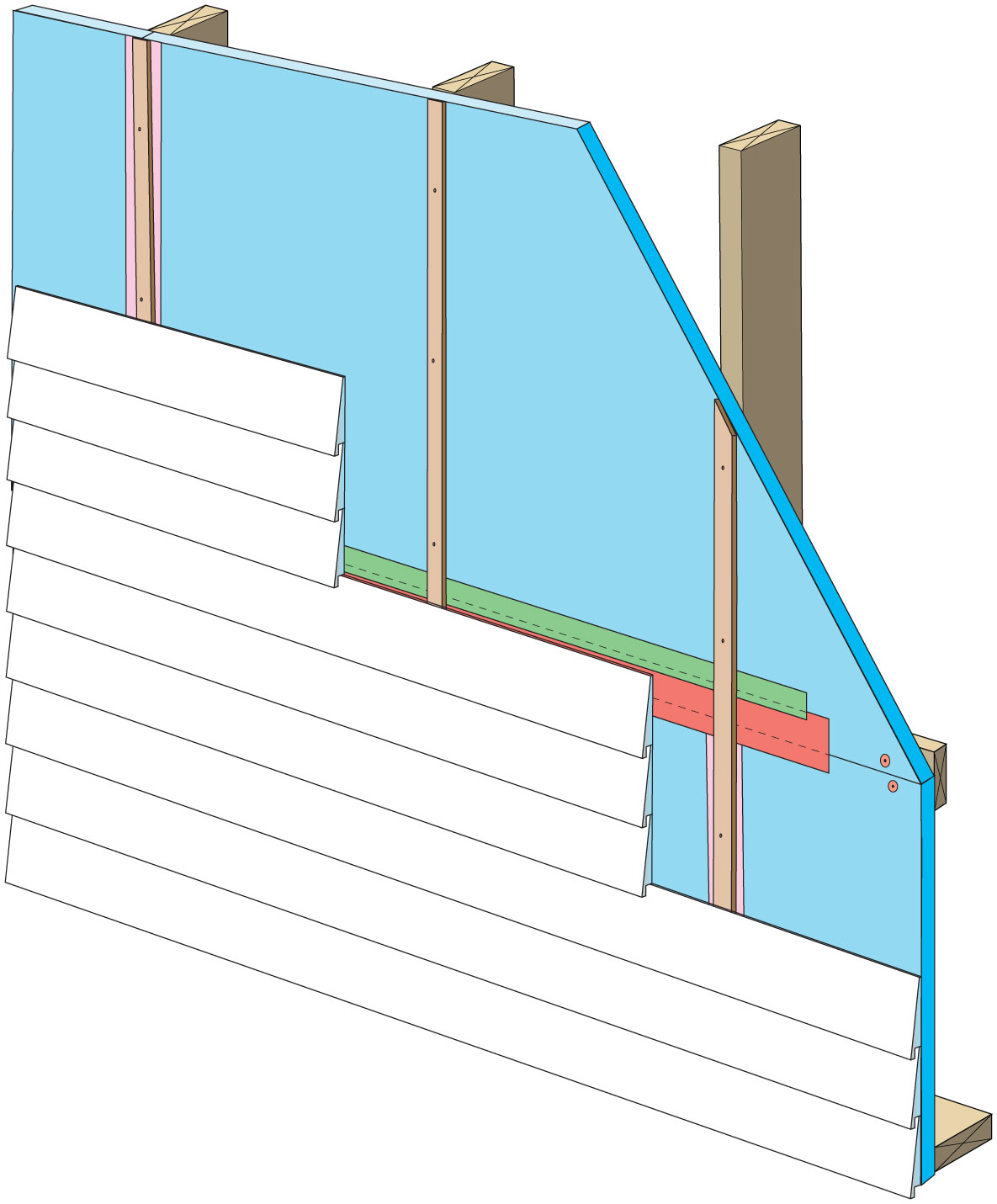
A piece of siding is used as sill extension and to provide slope in the opening for the window, which is deeper because exterior rigid foam has been added
Image
Image
Apply self-adhesive flashing over top edge of the wall flashing, diverter, and housewrap
Image
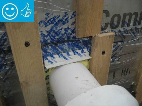
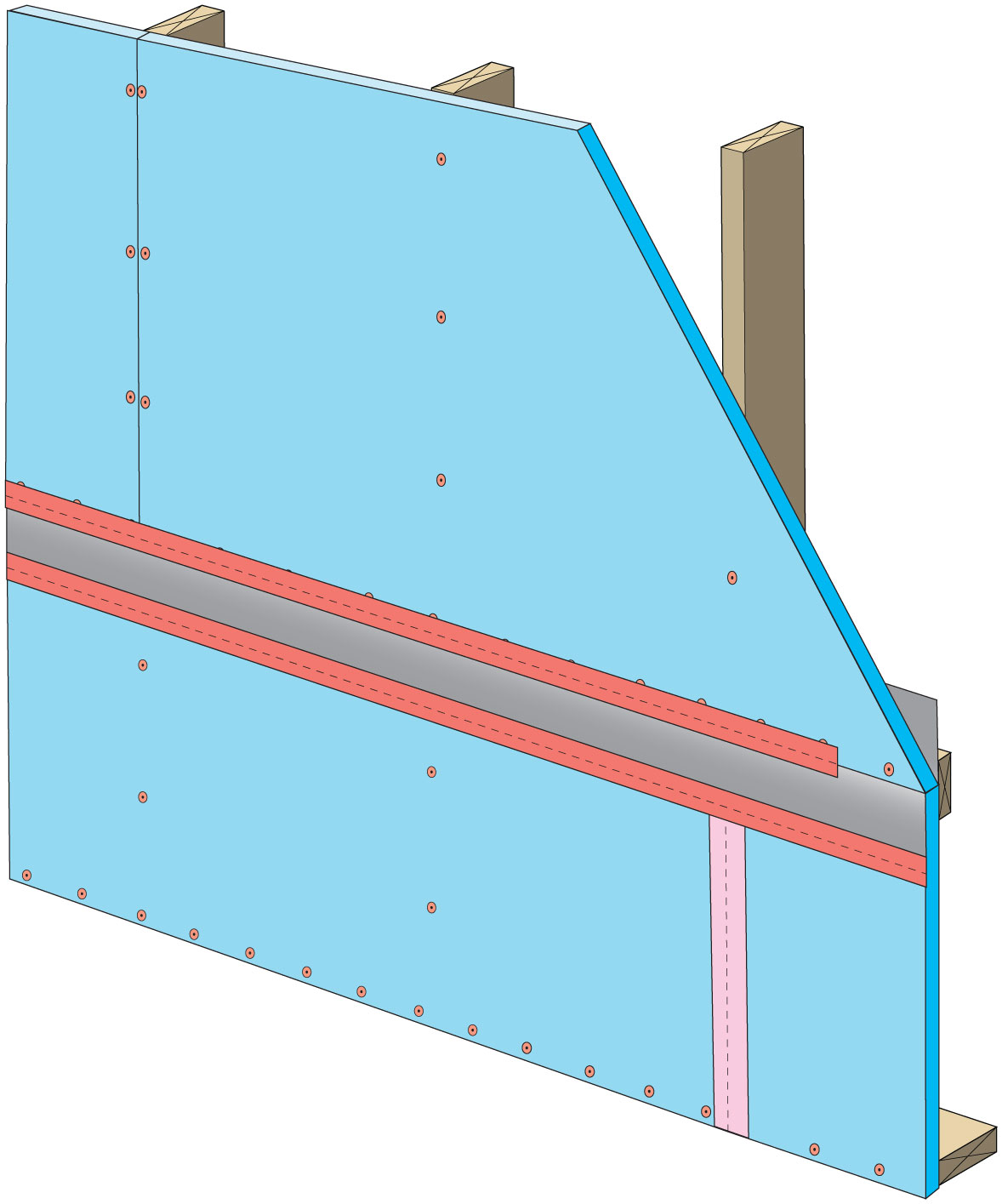
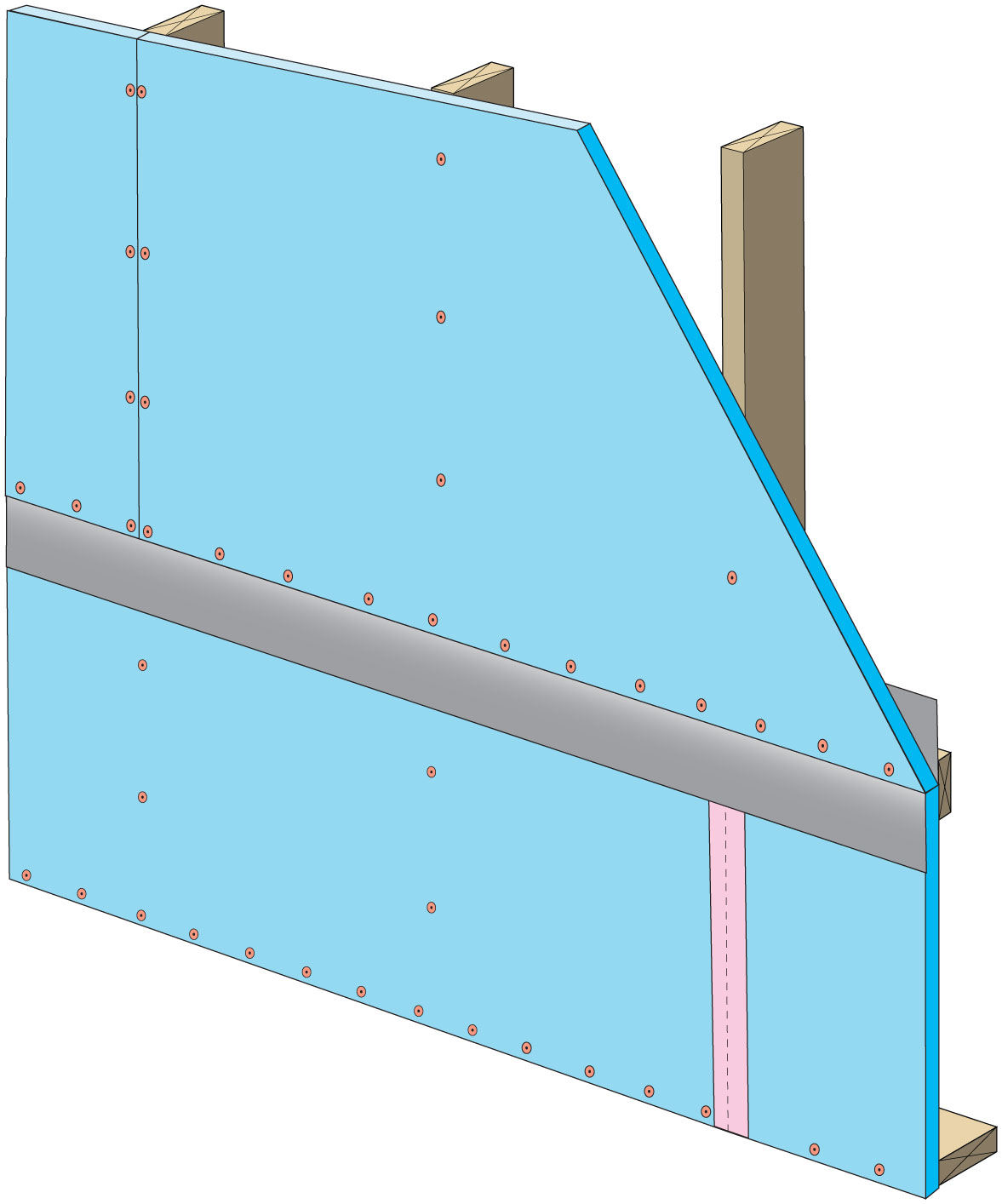
Clean taping areas and install 3" tape on vertical joint of upper insulation overlapping the horizontal joint
Image
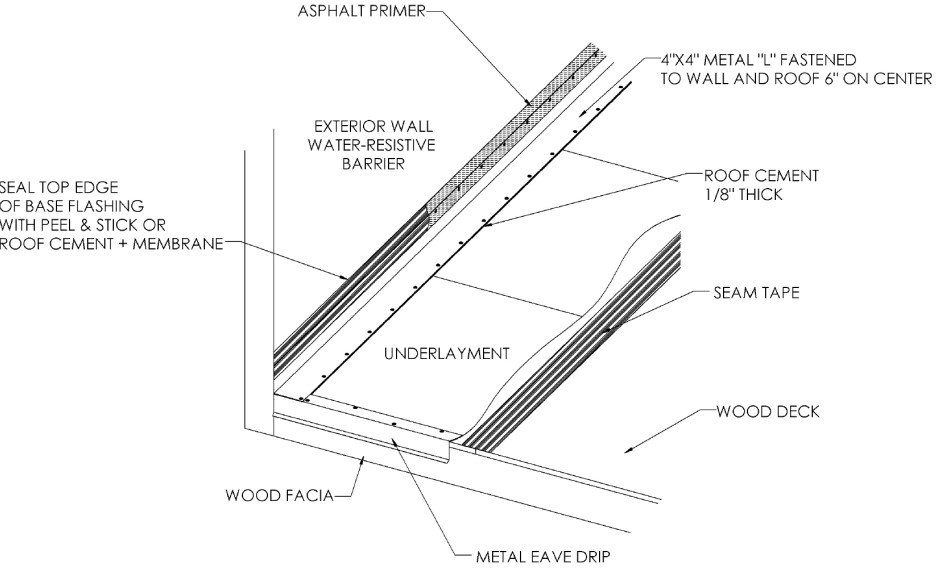
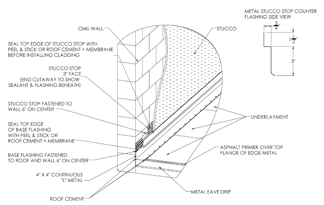
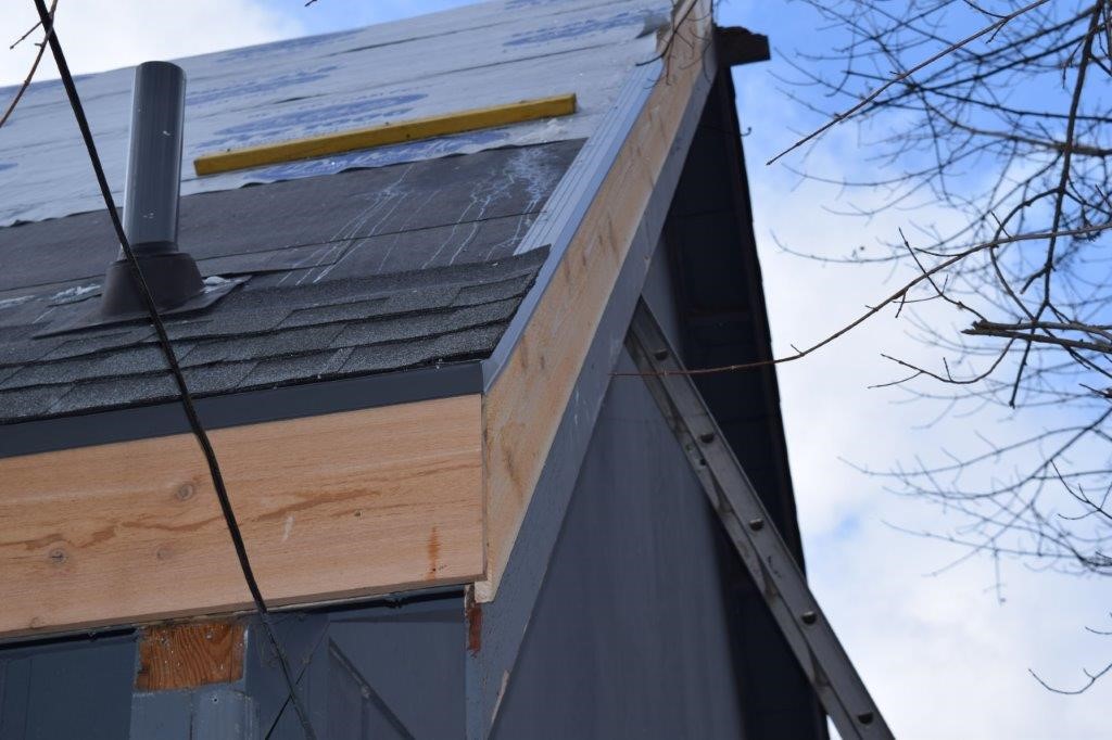
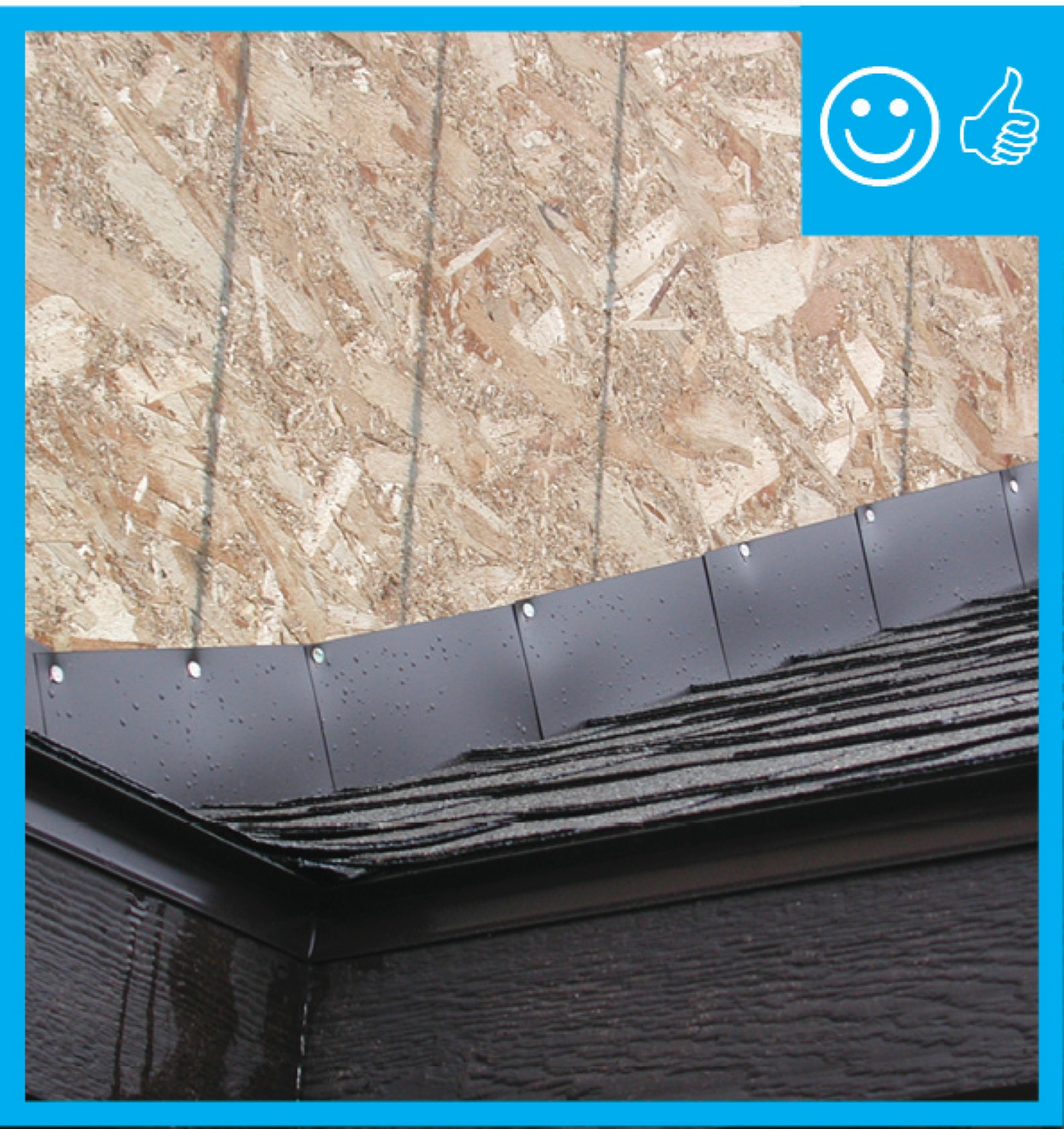
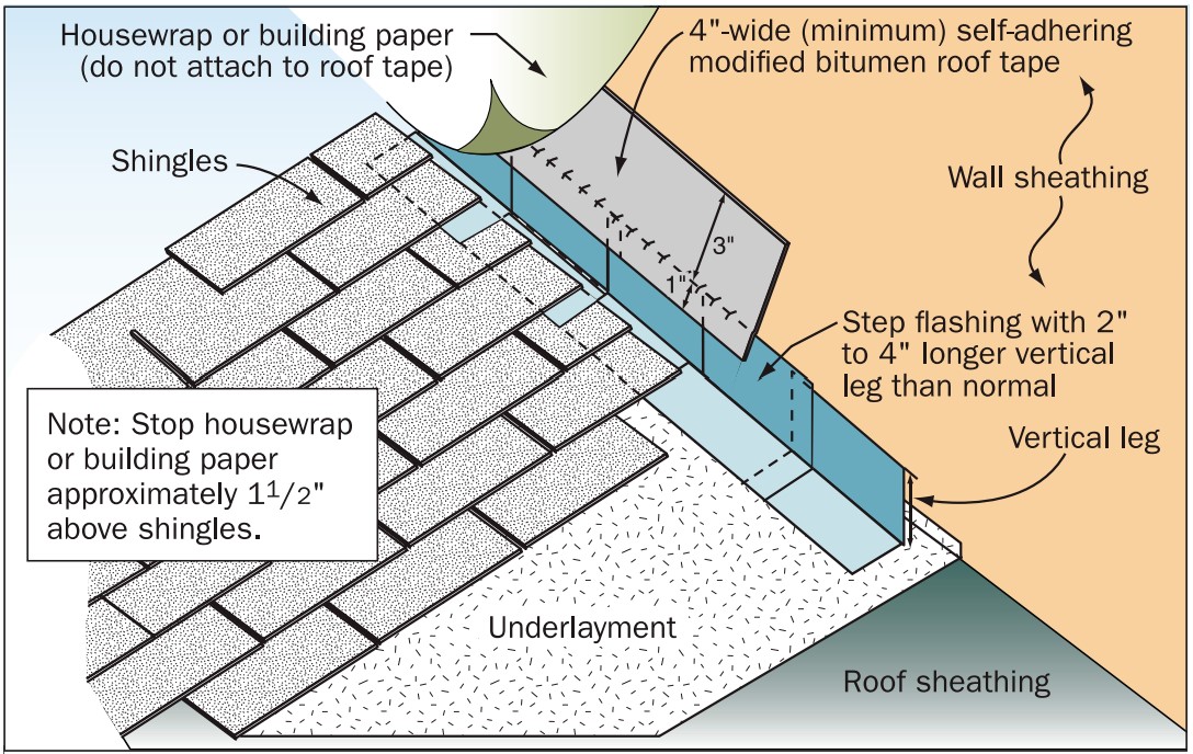
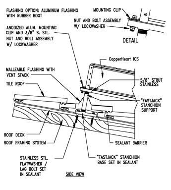
Continuous L-metal flashing integrated with underlayment at roof-wall intersections
Image
Image

Drip flashing at the door head and drip flashing with hook at the head help to keep out wind-driven rain.
Image
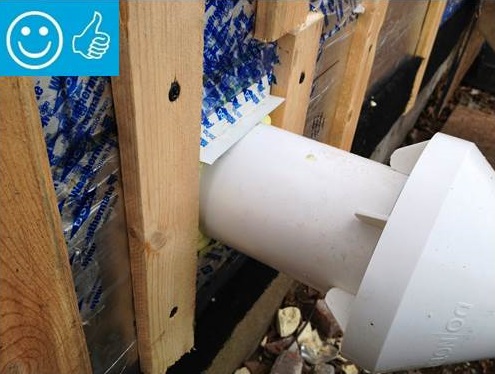
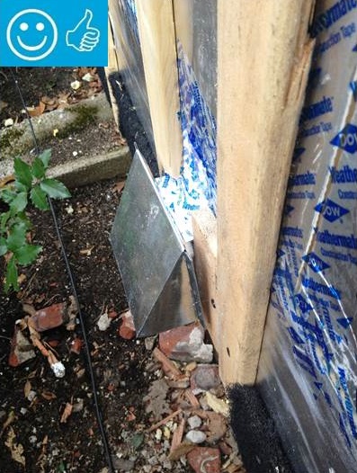
Duct/pipe penetration with metal cap flashing and wood blocking for trim attachment
Image
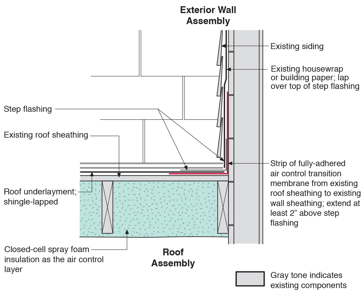
Existing wall-to-lower roof transition retrofitted with a new strip of fully adhered air control transition membrane, new step flashing, new roof underlayment, and new cladding
Image
Existing wall-to-lower roof transition with a new strip of fully adhered air control transition membrane, new step flashing, new roof underlayment, and new cladding – view from eave
Image
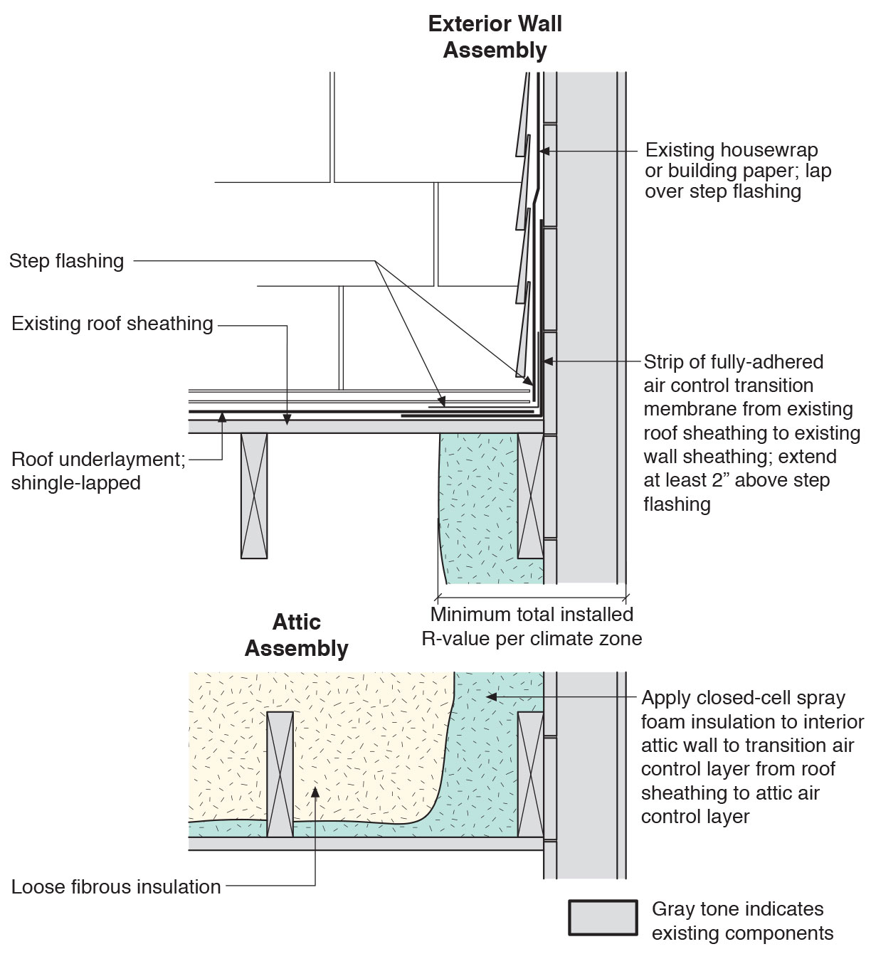
Existing wall-to-lower roof with attic transition with a new strip of fully adhered air control transition membrane, new step flashing, new roof underlayment, and new cladding – view from eave
Image
Image
Heavy metal flashing protects the deck timbers and separates them from the wall at the wall-deck connection which is vulnerable to both ember entrapment and water damage.
Image
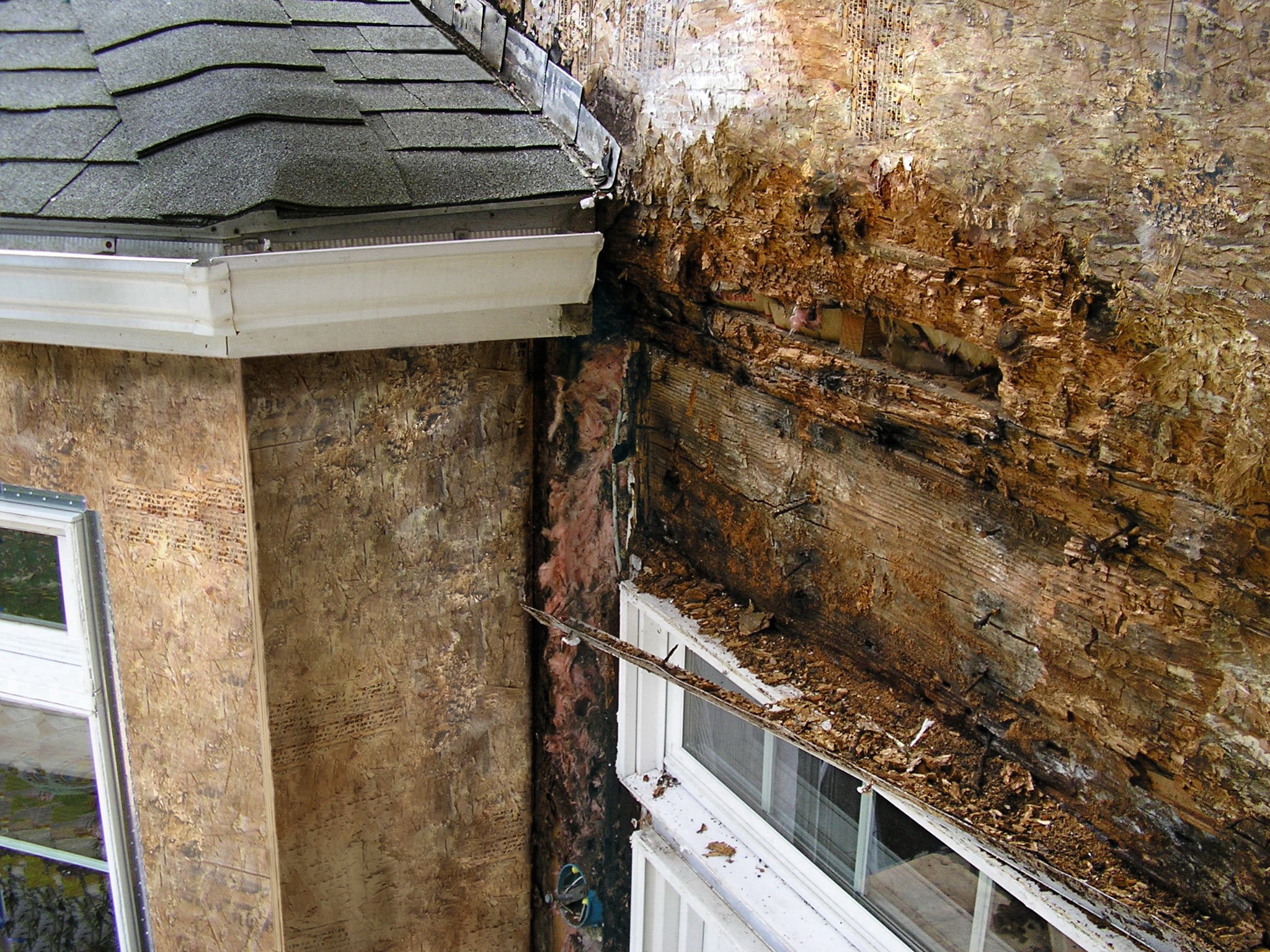
Improper flashing can allow rain water into walls, causing significant damage
Image
Image
Image
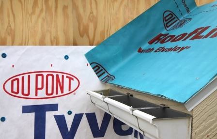
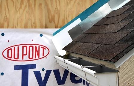
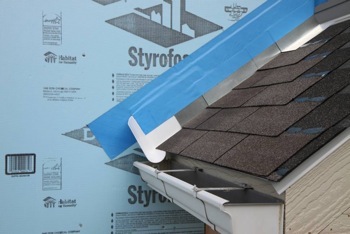
Install shingle starter strip then kick-out diverter; attach to roof deck but not sidewall
Image

Image

Image
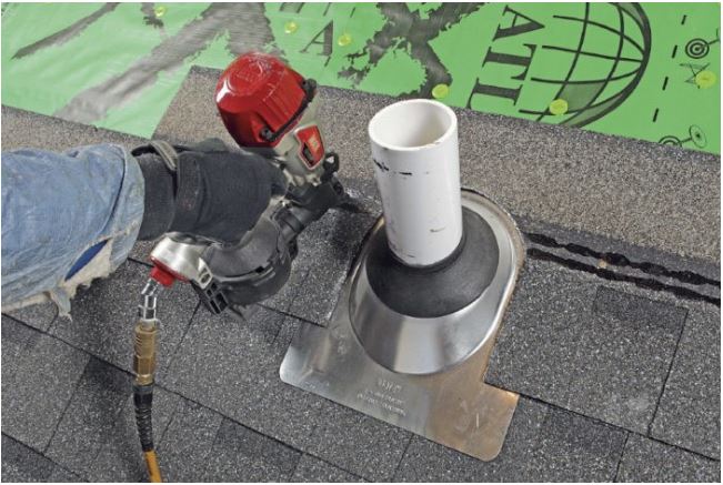
Integrate pre-formed vent pipe flashing, shingle-fashion, with roofing underlayment and shingles
Image
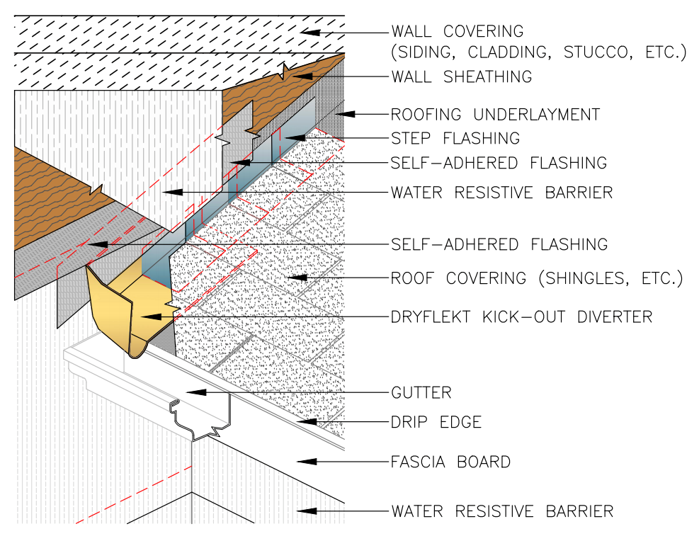
Kickout diverter flashing keeps bulk water from the roof from overflowing the gutter and continuously wetting the siding material.
Image
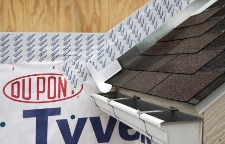
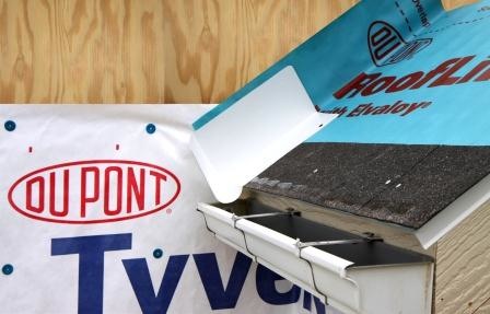
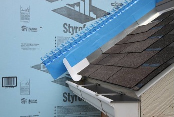
Place first shingle and next section of sidewall flashing over upper edge of diverter
Image
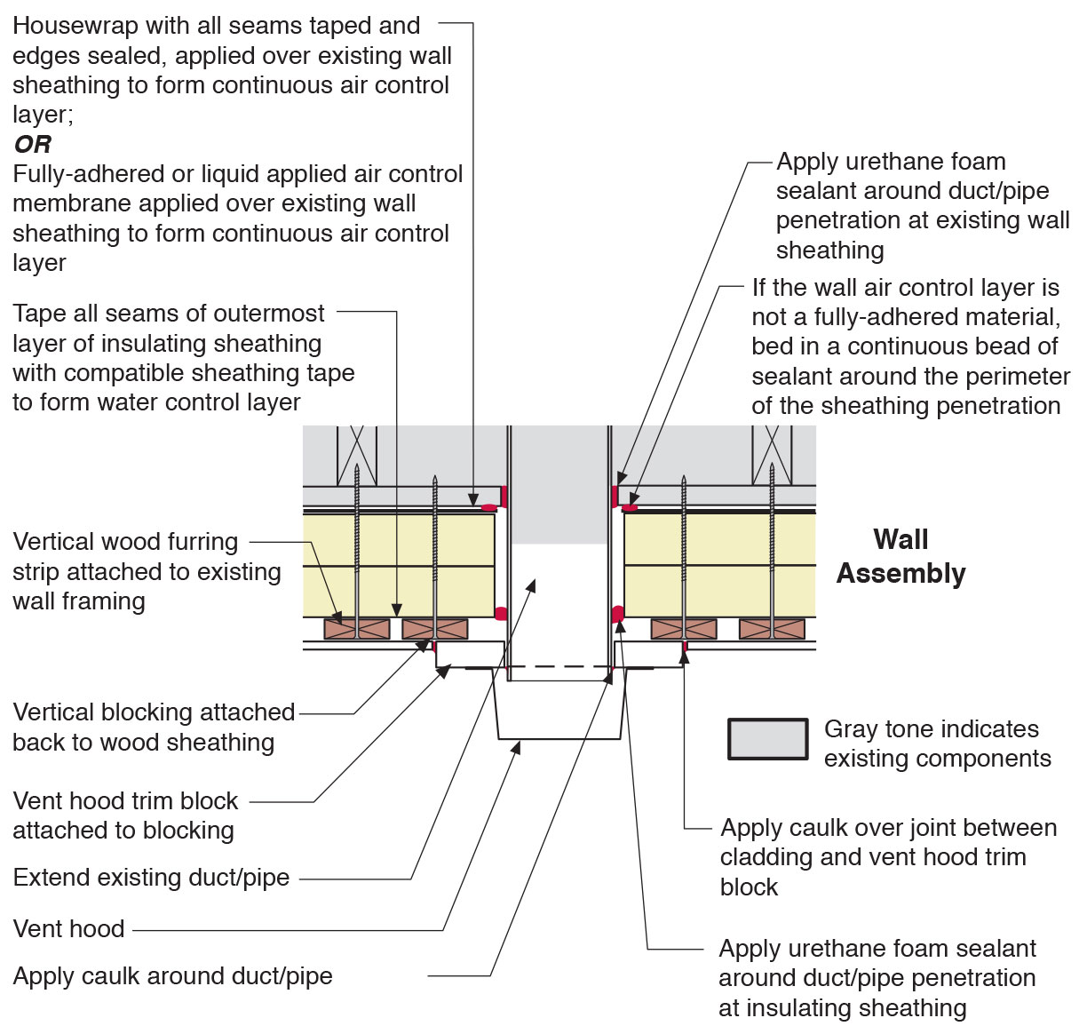
Plan view of duct or pipe penetration through exterior wall showing flashing and air sealing details
Image
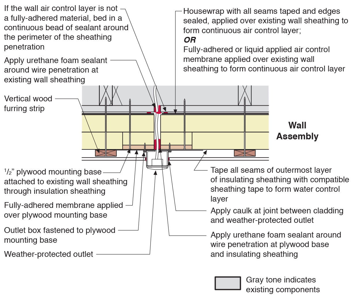
Plan view of electric box installation in exterior wall showing flashing and air sealing details
Image
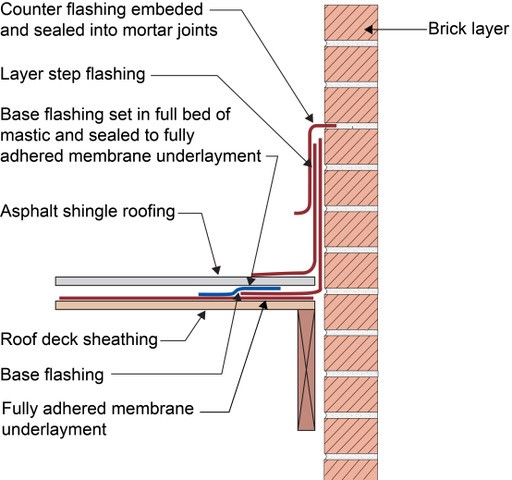
Right - Counterflashing tops a layer of step flashing which comes down above the asphalt shingle and a layer of L-shaped base flashing which comes down and extends below the shingle; the base flashing is adhered to the roof underlayment with mastic, shown
Image
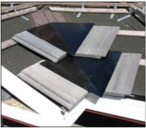
Right - Pieces of metal flashing are installed under each tile course along the valley centerline to prevent debris accumulation between and below concrete roof tiles.
Image
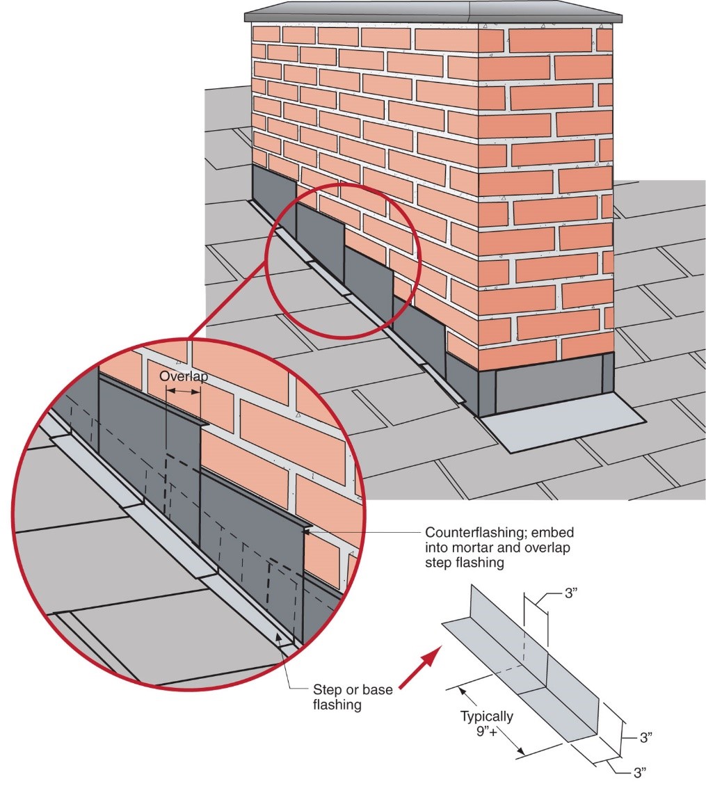
Right - Step flashing along a chimney is integrated in a layered manner with asphalt shingle roofing and topped with counterflashing that is embedded into brick mortar joint above
Image
Right - The duct shows redundant sealing including the caulk, tape, and flashing
Image
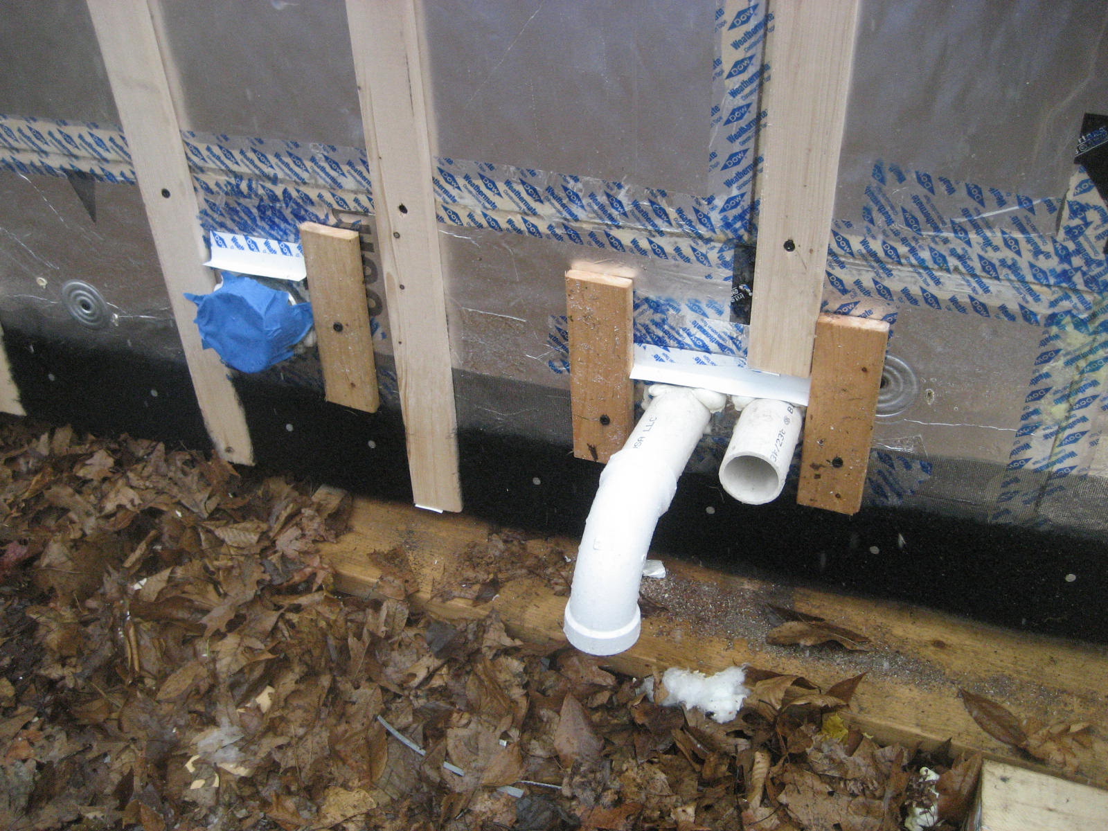
Right - The pipe penetration is properly flashed and furring strips are installed on each side in preparation for installing cladding
Image
Image
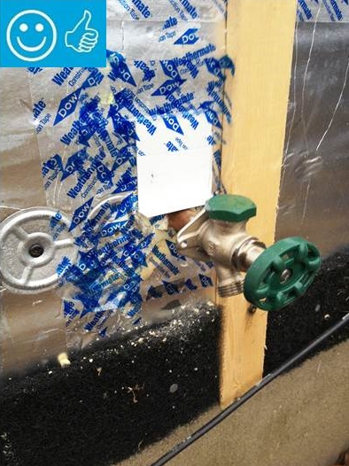
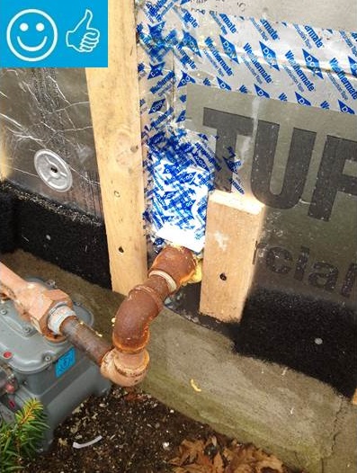
Right - The water and air control layers are properly integrated around the hose bib
Image
Right - This duct penetration is properly flashed and integrated with the taped, foil-faced foam sheathing layer, which serves as the air and water barrier
Image
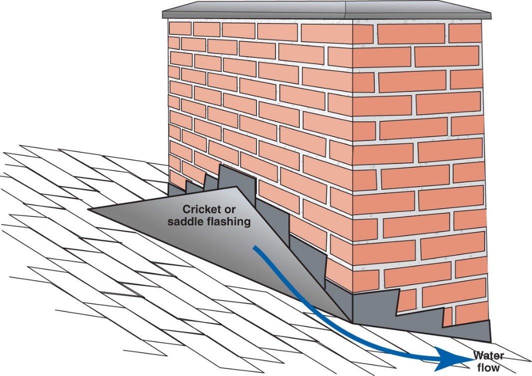
Right – A chimney cricket is installed and flashed to direct rainwater around the chimney
Image
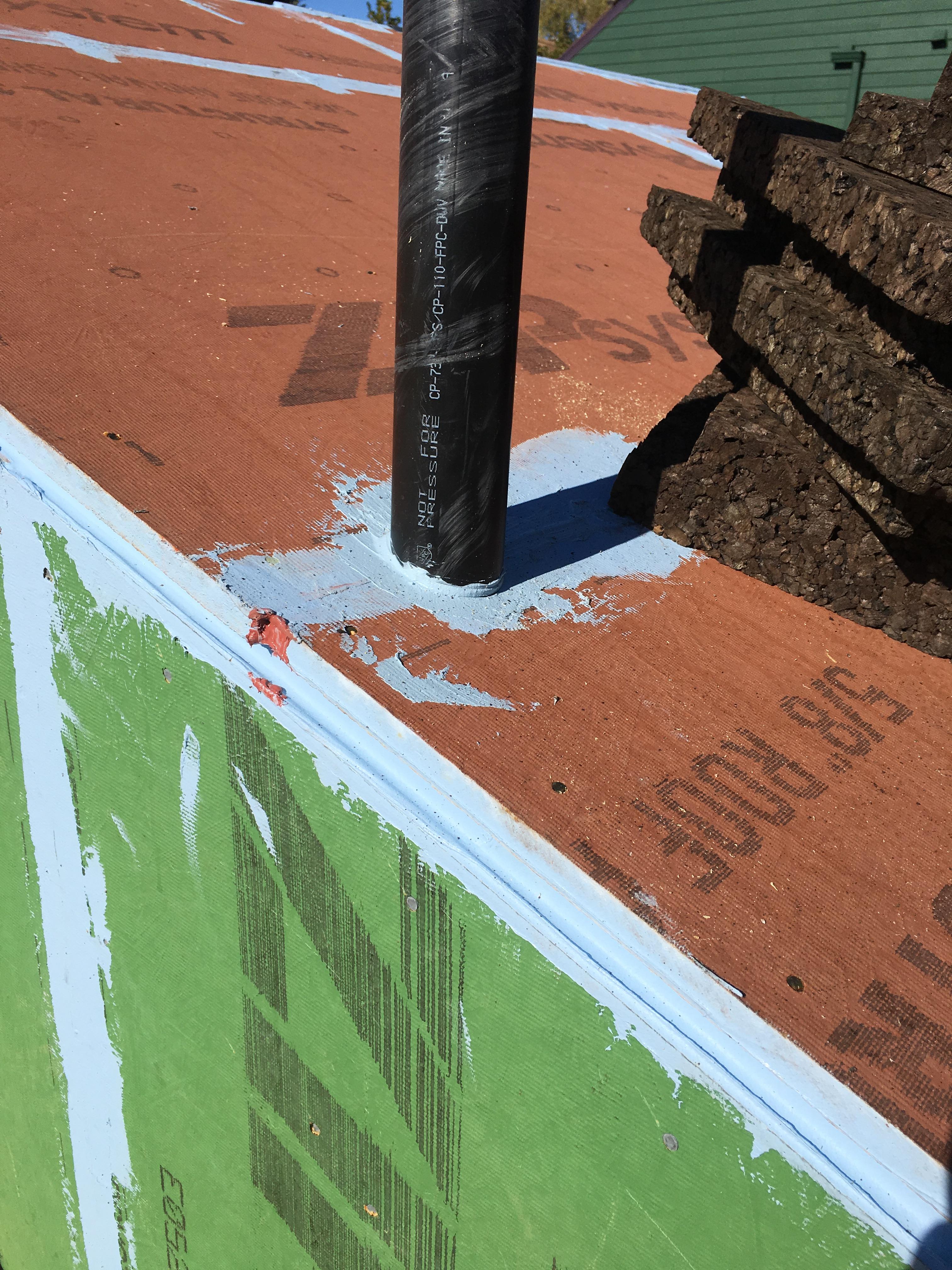
Right – All penetrations through the roof decking are sealed with paint-on flashing.
Image
Right – Deck flashing protects the deck-to-wall connection from water and burning embers.
Image
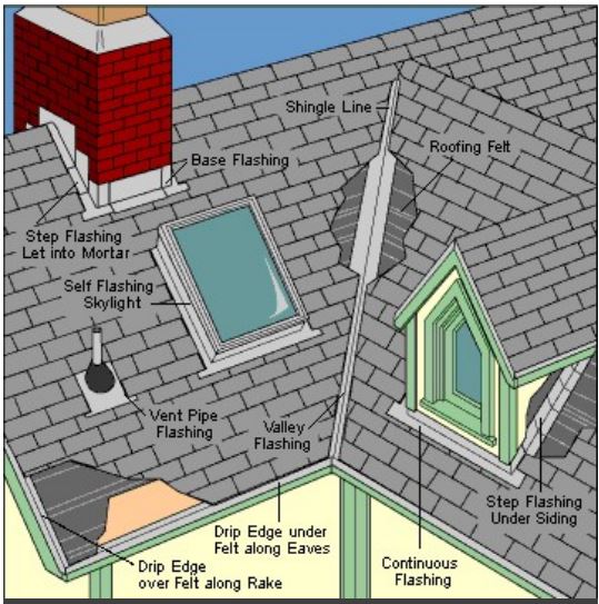
Right – Flashing is installed around chimney, skylight, vents, dormers, in valleys and at eaves
Image
Image
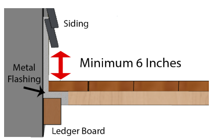
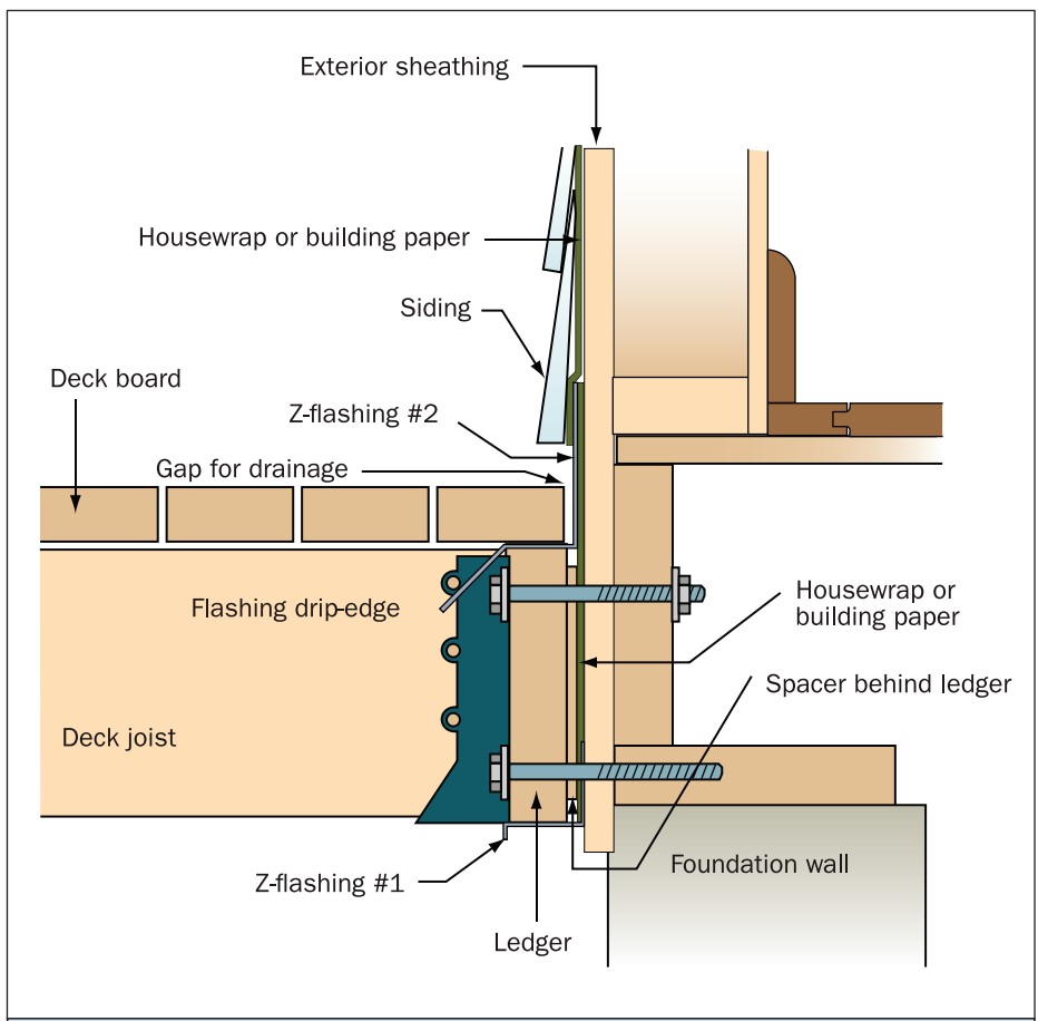
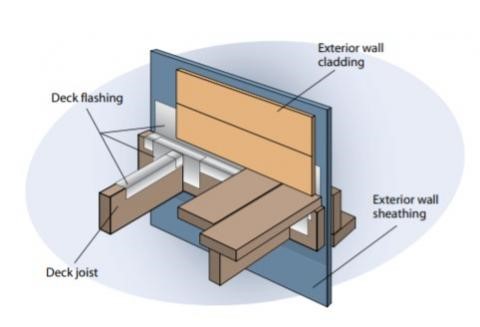
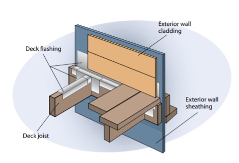
Right – Metal flashing is installed between the deck boards and house wall with the top of the flashing extending up behind the siding and the bottom of the flashing extending out and down over the ledger board
Image
Image
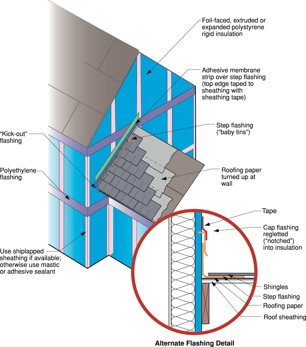
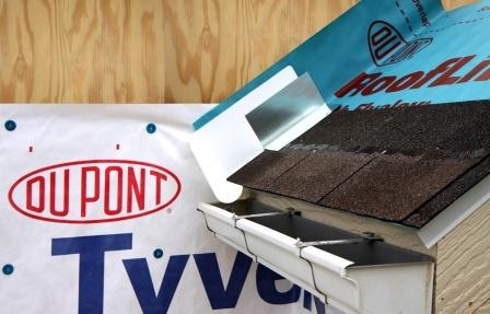
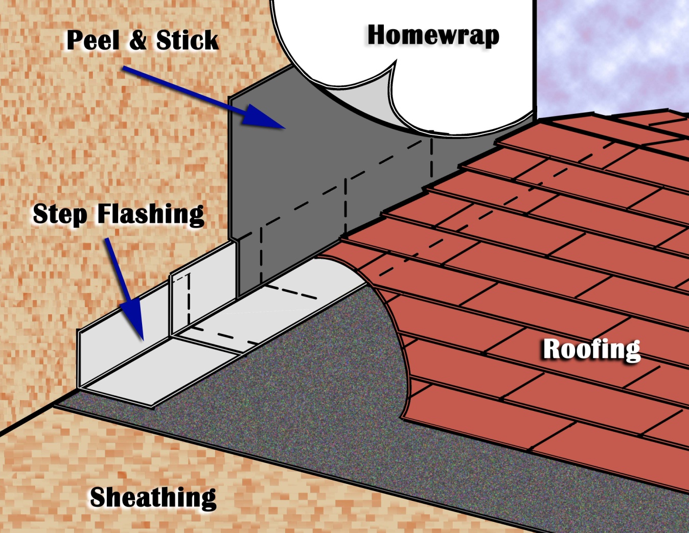
Right – The water-resistant barrier is layered over the step flashing to provide a complete drainage system
Image
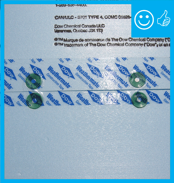
Right – Two-thirds of acrylic tape is offset above the joint and over and above the fasteners
Image
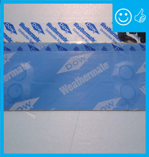
Right – two-thirds of the blue butyl flashing tape is above the sheathing seam; the top edge of the butyl flashing tape is covered with clear sheathing tape that is also offset so two-thirds is above the top edge of the butyl flashing.
Image
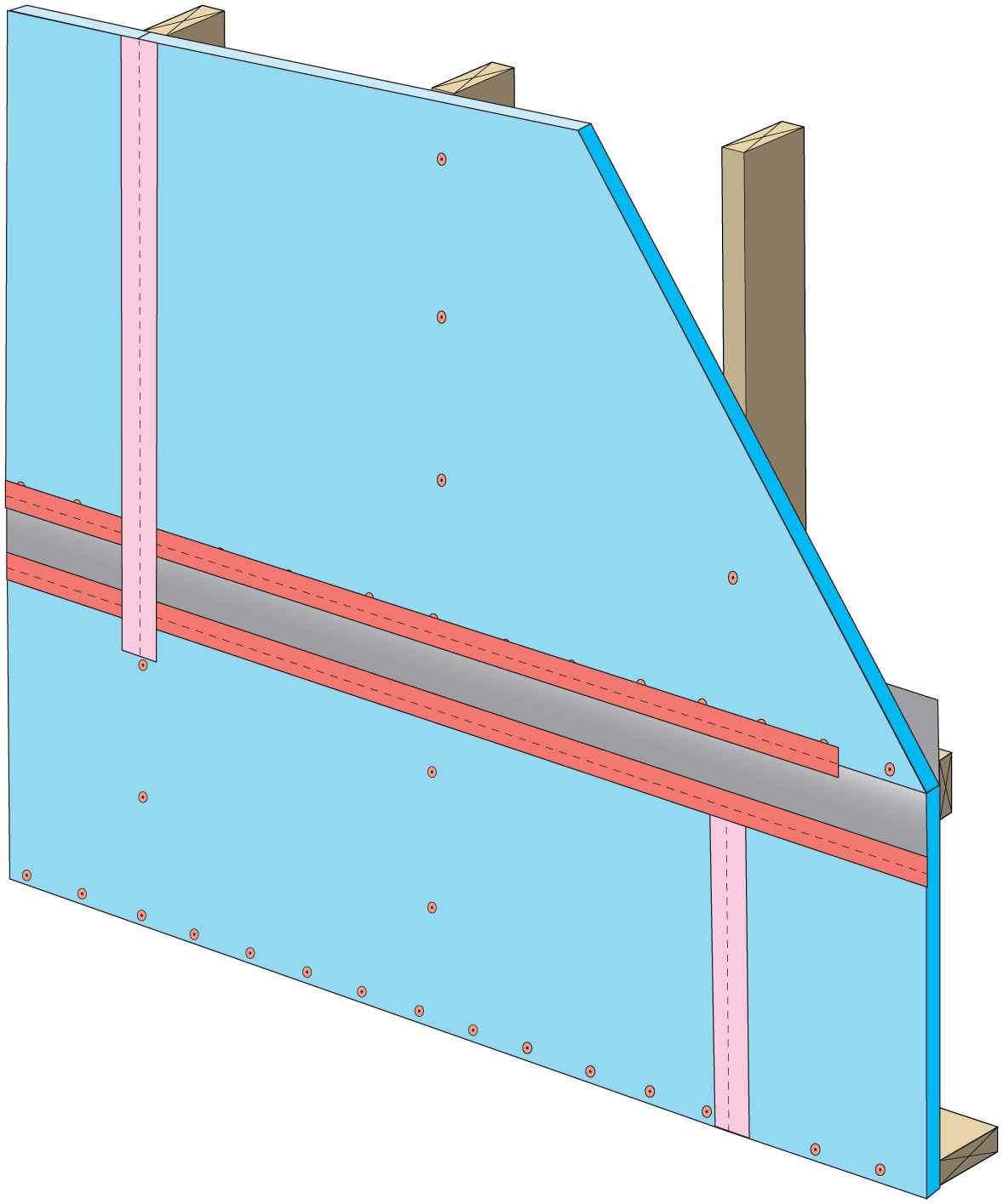
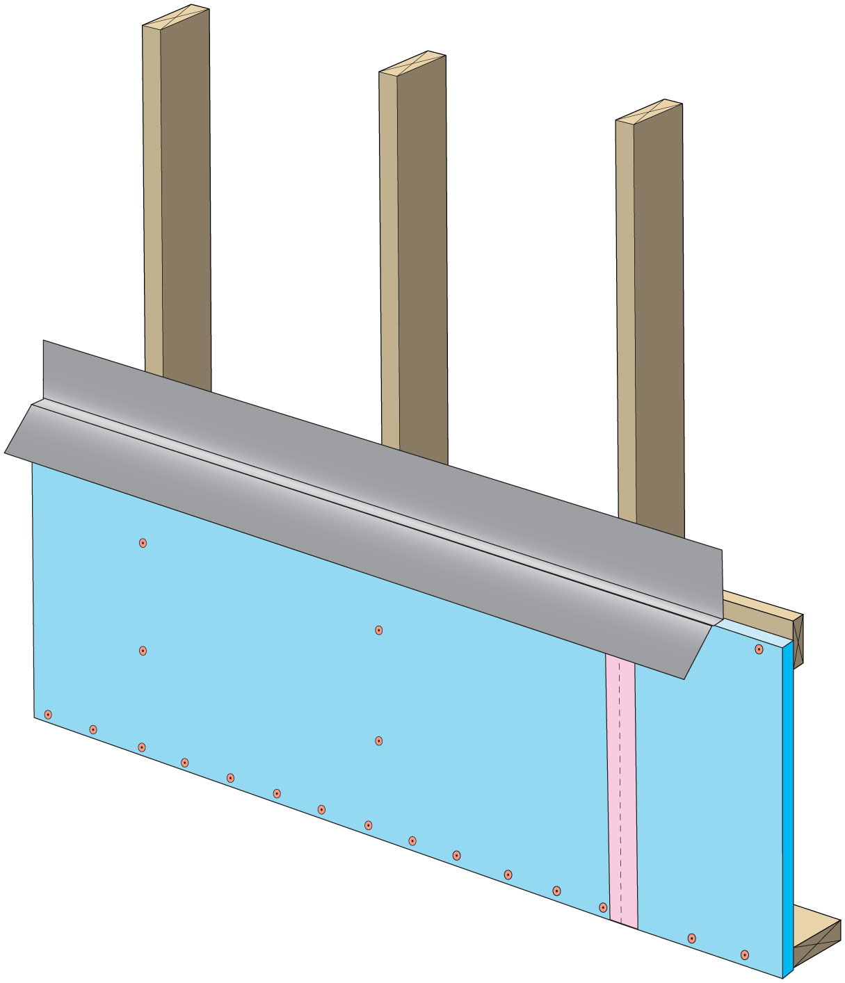
Rigid foam insulation can serve as the drainage plane when all seams are taped. Furring strips provide an air gap behind the cladding.
Image
Image
Image
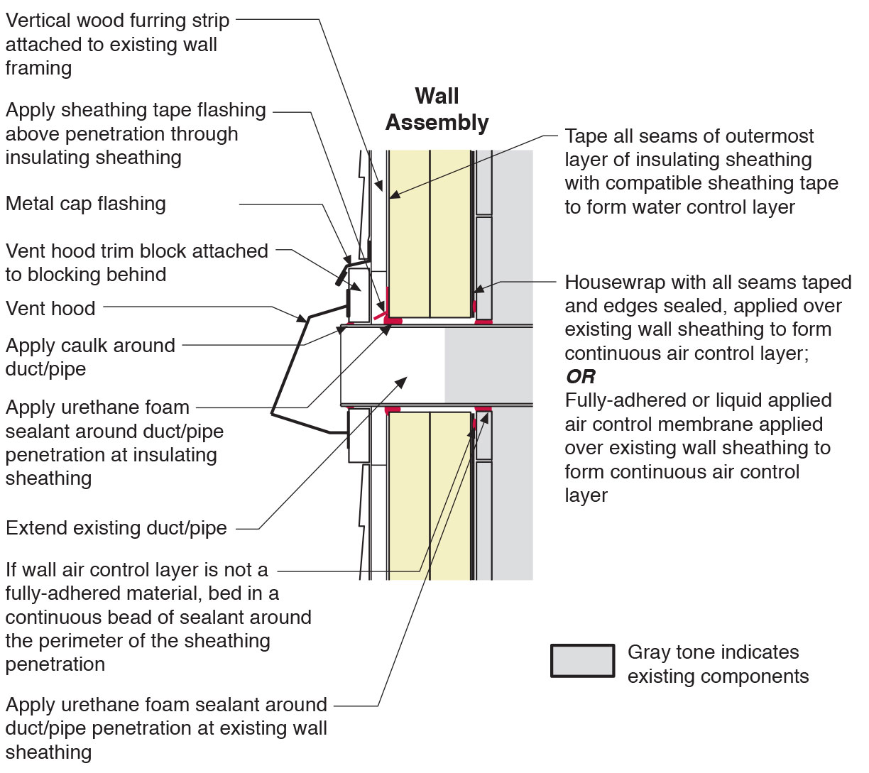
Section view of duct or pipe penetration through exterior wall showing flashing and air sealing details
Image
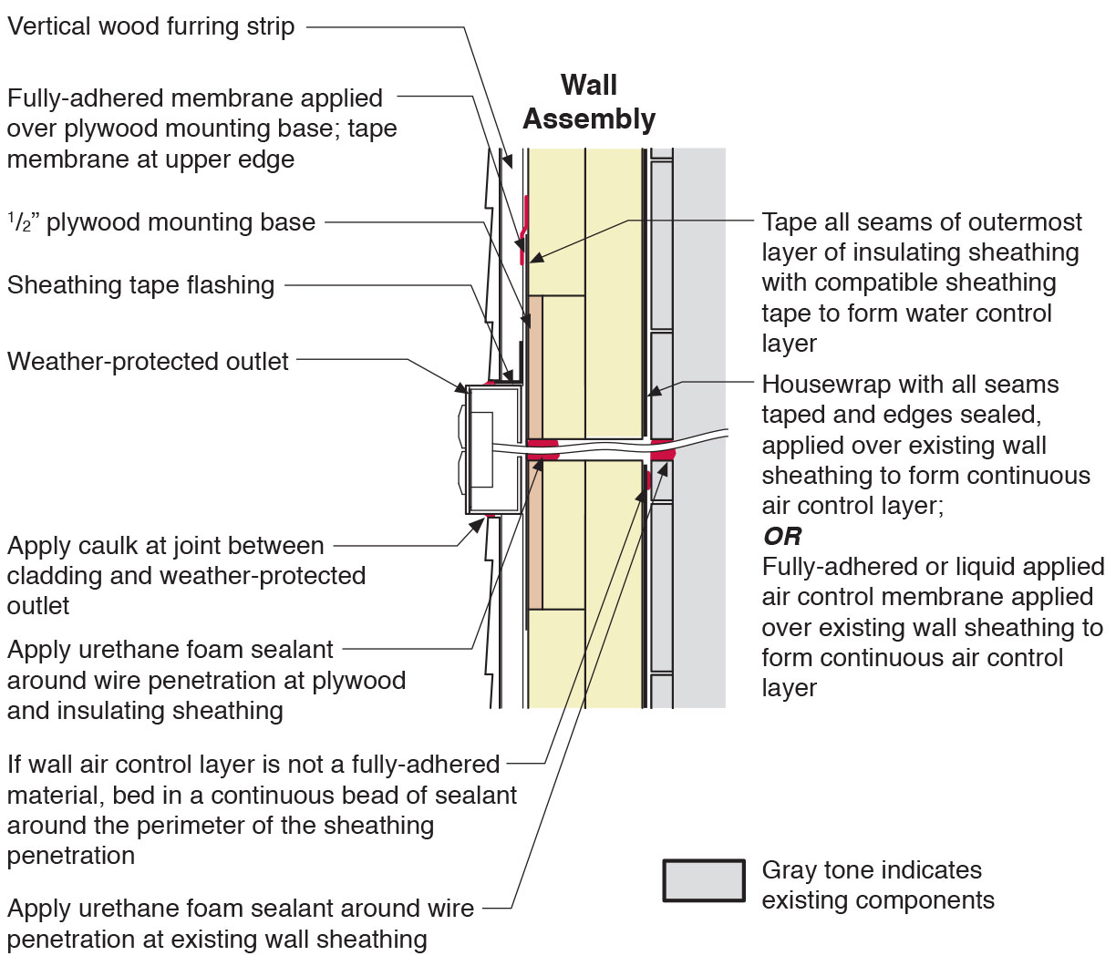
Section view of electric box installation in exterior wall showing flashing and air sealing details
Image
Image
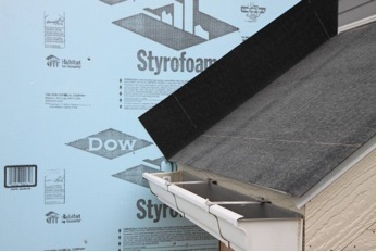
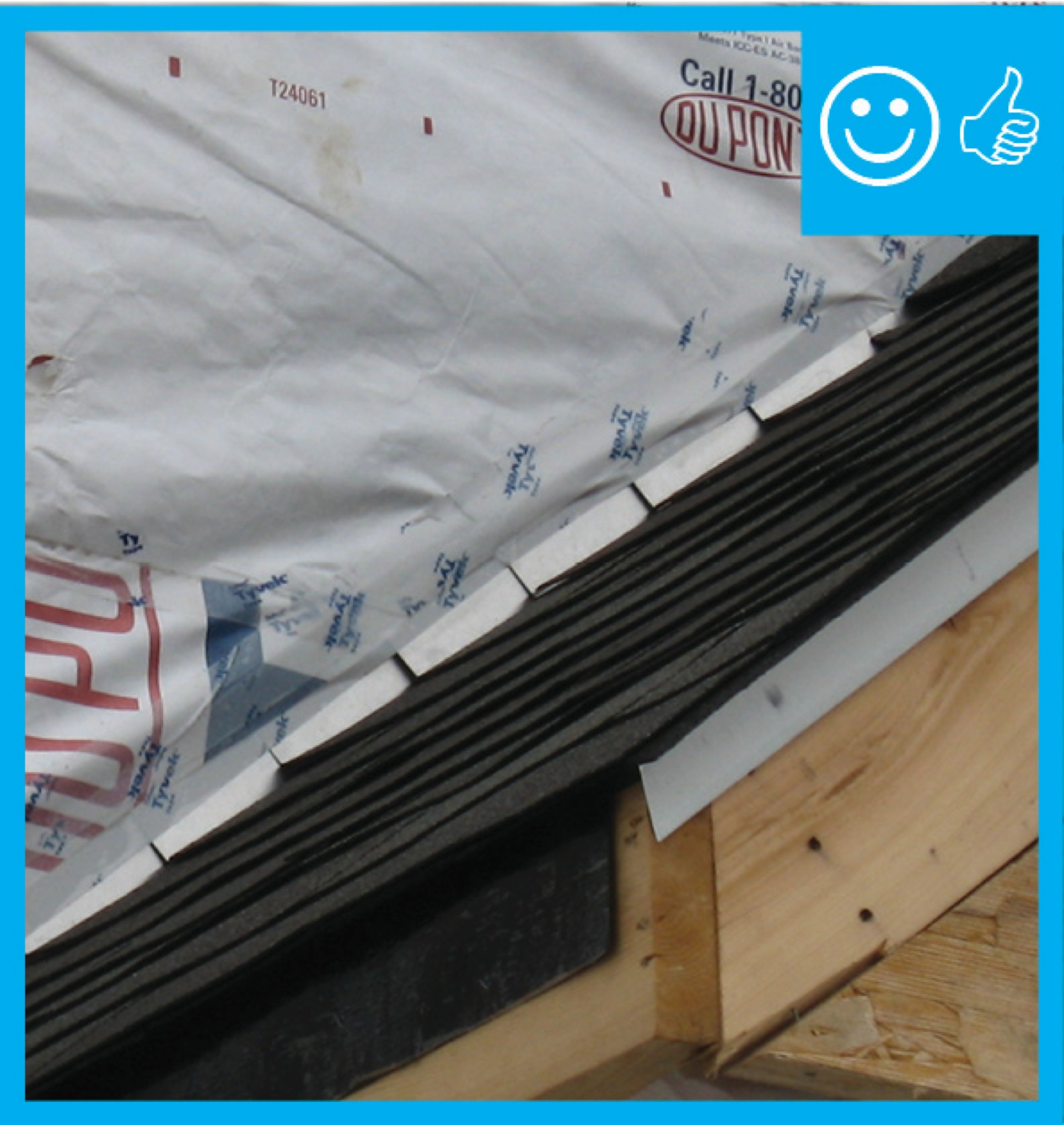
Step 1. Apply roof underlayment over roof deck and up the sidewall over the rigid foam insulation
Image
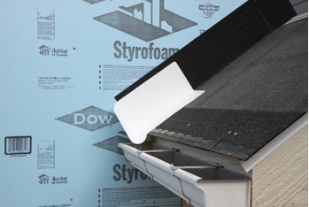
Step 2. Install shingle starter strip then kick-out diverter as first piece of step flashing.
Image
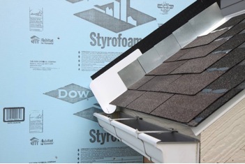
Step 4. Install remaining sidewall flashing, appropriate counter flashing, and shingles
Image
Step 5. Apply self-adhesive flashing over top edge of the wall flashing, diverter, and rigid foam insulation
Image
Image
Tape the joint between the top insulation sheet and the Z-flashing with 2" wide tape to improve air tightness
Image
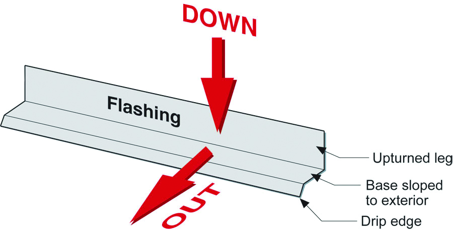
The “down” and “out” approach to flashing – metal flashing directs water down and out of building assemblies
Image
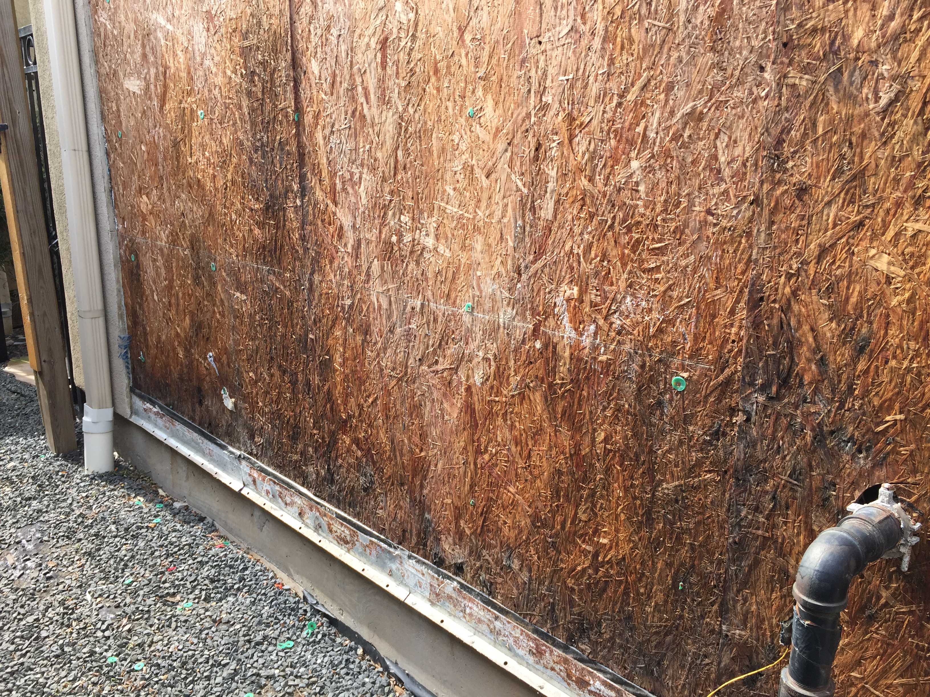
The sheathing has rotted because there was not a sufficient drainage gap behind the stucco cladding
Image
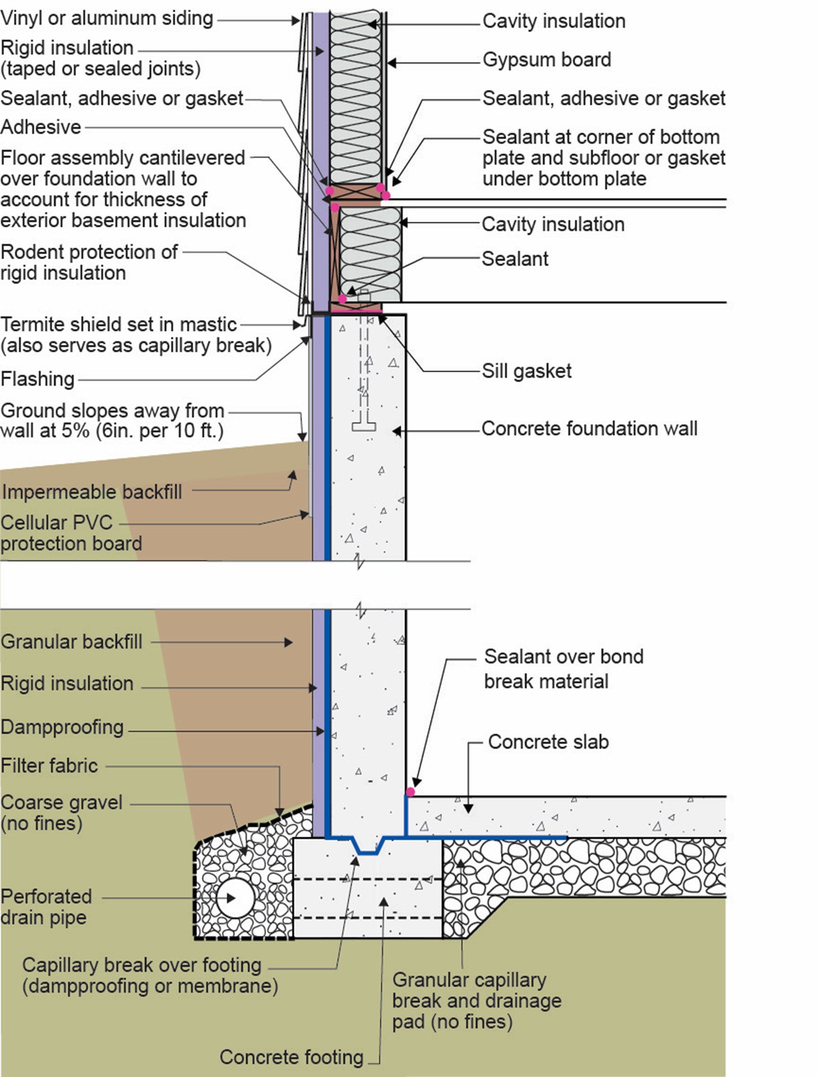
This basement is insulated on the exterior with rigid foam over dampproofing, with granular backfill and footing drains to facilitate drainage away from the foundation, a termite shield to protect from pests, and cellular PVC to protect the rigid foam.
Image
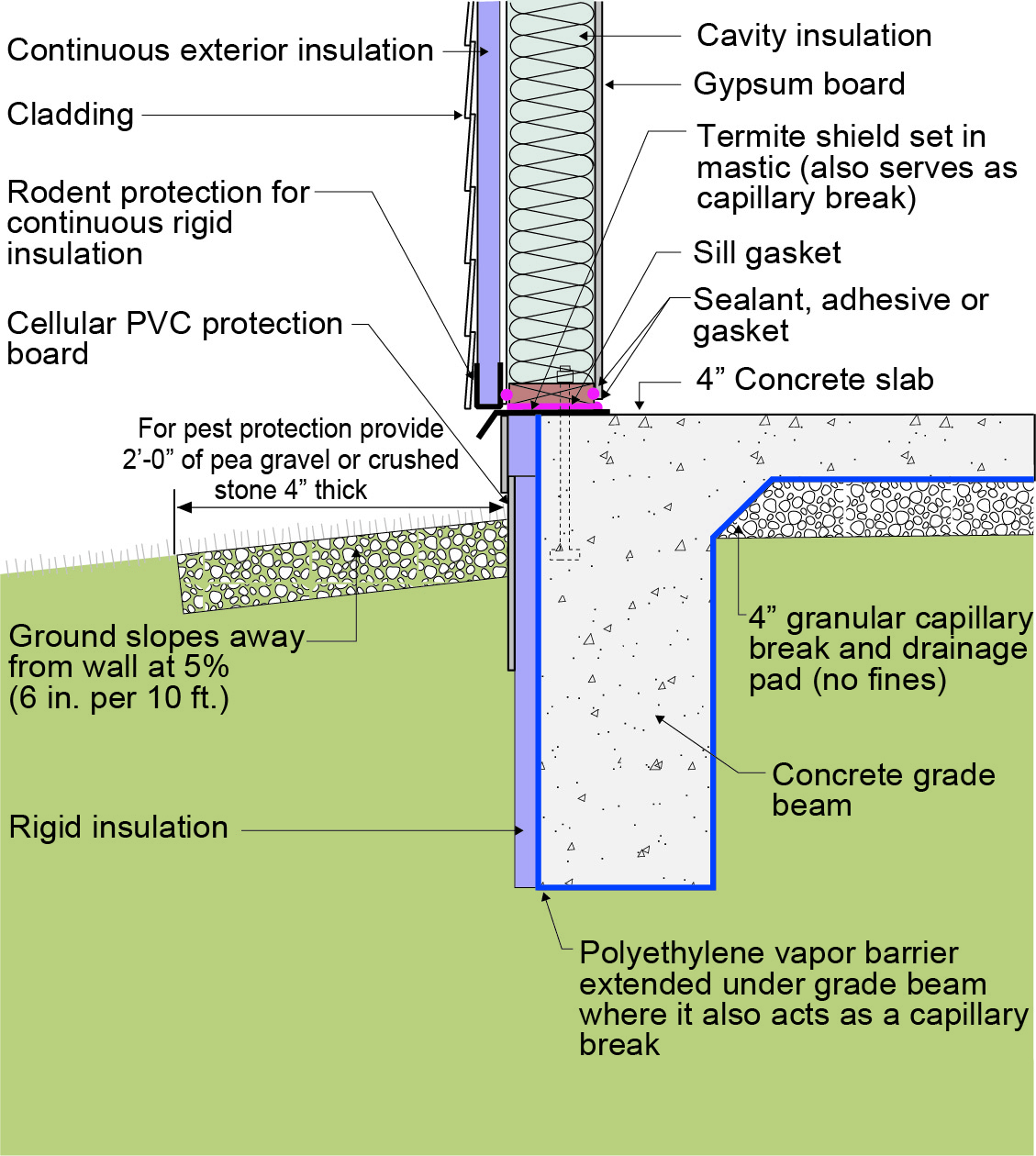
This exterior insulated slab-on-grade monolithic grade beam foundation is protected from pests by termite shield at the sill plate, borate-treated framing, flashing at end of wall insulation, brick veneer over slab-edge insulation, and rock ground cover.
Image
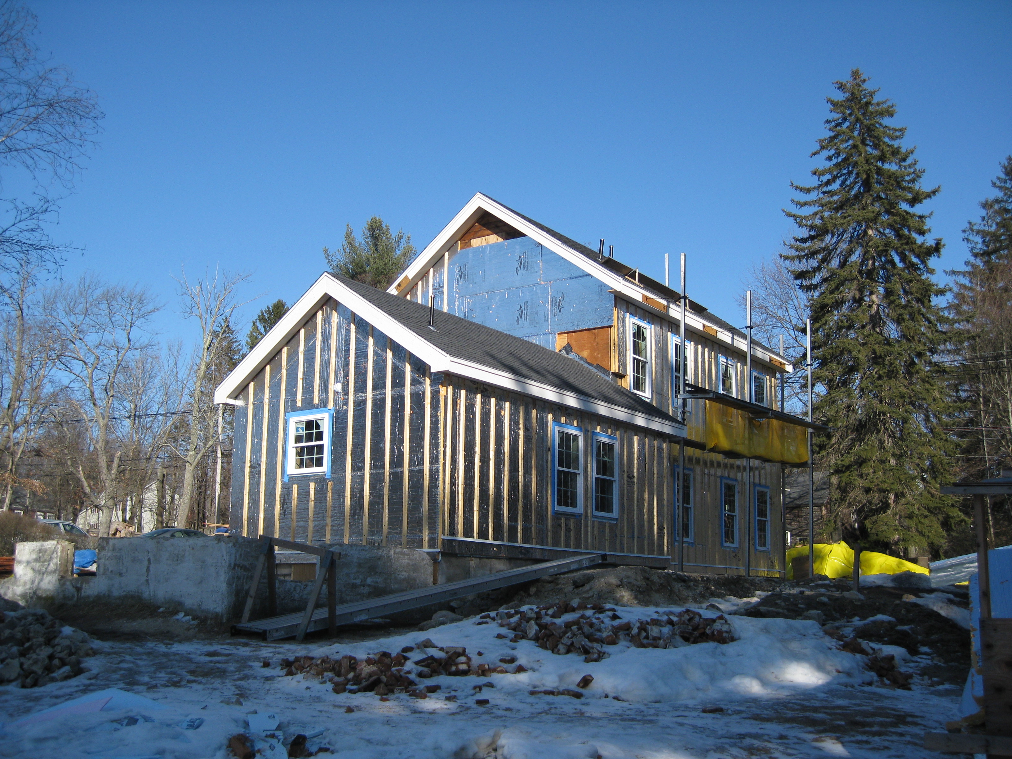
This farmhouse was retrofit by removing the existing siding and adding taped insulated sheathing and battens before installing new siding
Image
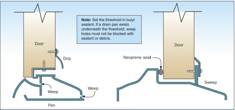
Threshold Sweep Flashing protects the door and helps to keep out wind-driven rain.
Image
Image
Image
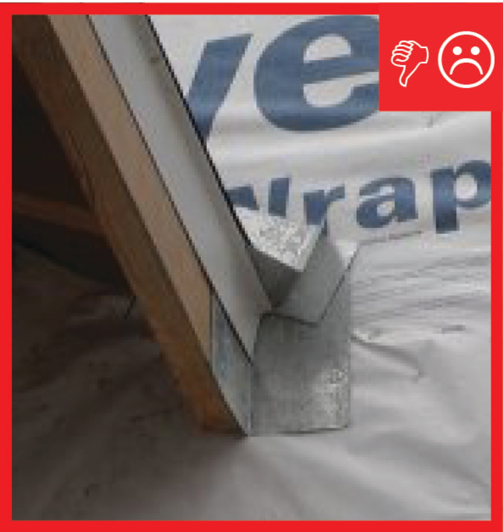
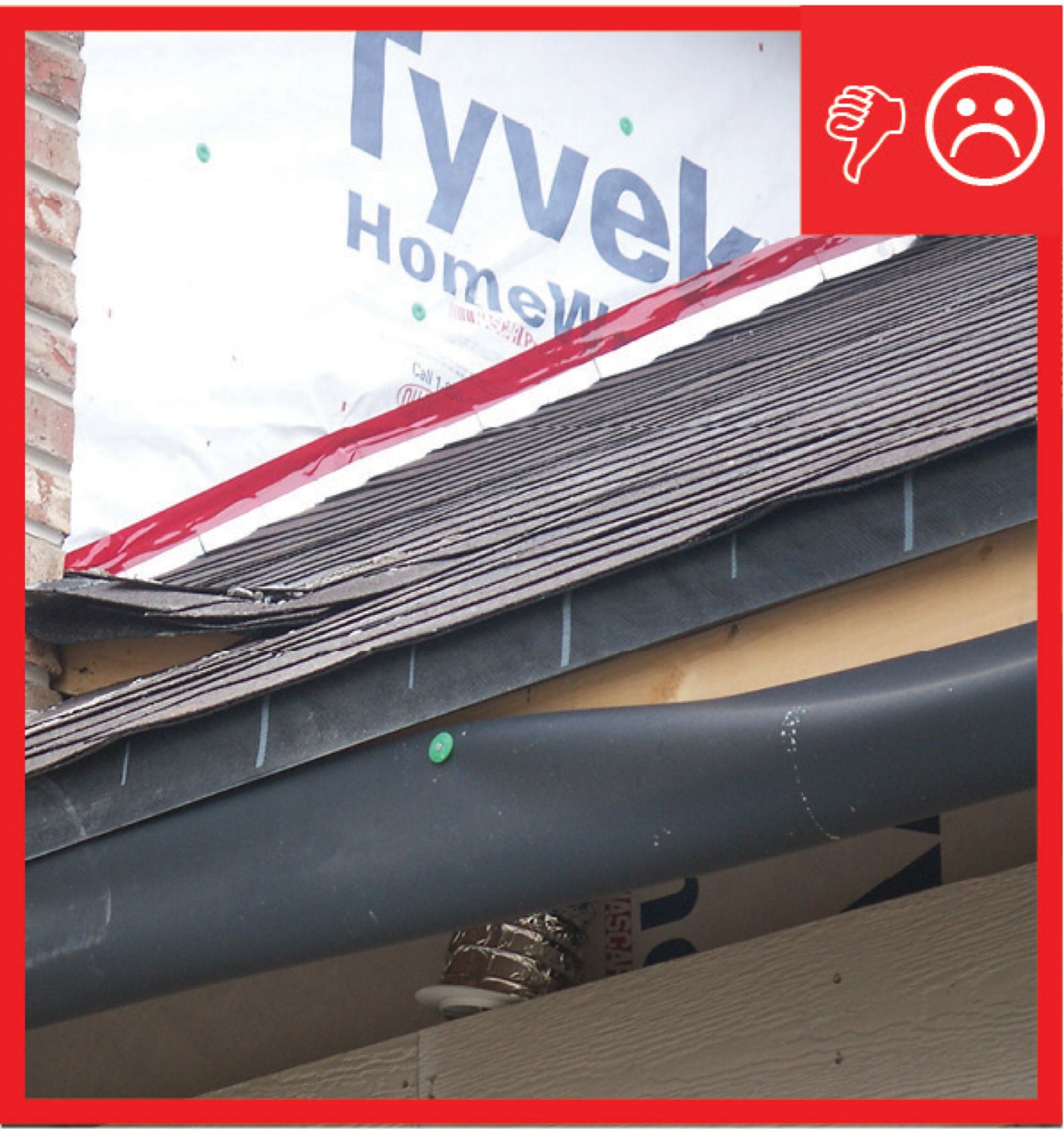
Wrong – the water-resistant barrier is layered underneath the step flashing, which could allow water to get behind the step flashing and into the wall.