

Drawings
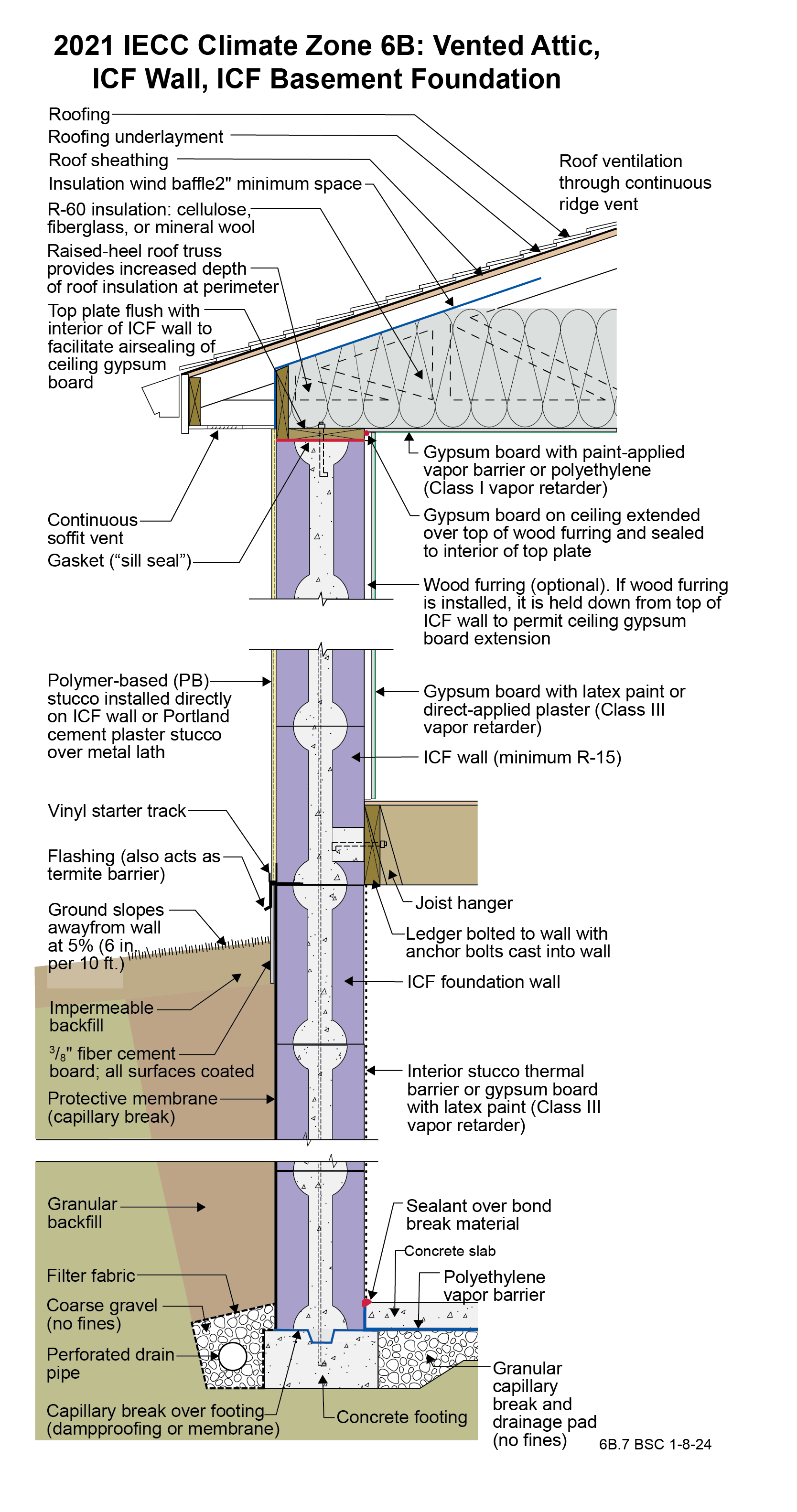
2021 IECC Climate Zone 6B: Vented Attic, ICF Wall, ICF Basement Foundation
Notes
Drawing 6B.7: IECC CZ 6: Vented Attic, ICF Wall, ICF Basement Foundation
- The function of the raised-heel roof truss is to control the temperature of the interior corner where the exterior wall meets the ceiling to control dust marking and mold. The minimum thermal resistance over the top of the wall assembly should match or exceed the thermal resistance of the wall assembly. Increasing the height of the raised heel can allow lower attic insulation levels by code. Per IECC 2021 Section R402.2.1, Ceilings with Attics, the ceiling insulation of this assembly can be R-49 rather than R-60 if the raised-heel roof truss is high enough to facilitate R-49 over the entire wall.
- The ceiling gypsum board is installed prior to the wall gypsum board in order to accommodate a “filet” bead of sealant that seals the ceiling gypsum board to the top plates creating a continuous air control layer (“air barrier”) across the entire ceiling including interior partition walls.
- ICF assemblies need an interior thermal barrier for fire protection – either gypsum board or stucco.

2021 IECC Window Detail: Framed Wall with a WRB, Rigid Insulation, and Siding (Wood, Fiber Cement, Aluminum or Vinyl) or Stucco
Notes
Window Detail 6A - Framed Wall with a WRB, Rigid Insulation, and Siding (Wood, Fiber Cement, Aluminum or Vinyl) or Stucco
- Note: Always follow the window manufacturer’s installation guidance. Not following manufacturer guidance may void the warranty.
- This is a “drained wall”. Drainage occurs outside of the water resistive barrier (WRB). A drainage gap between the WRB and the rigid insulation is created by installing “cap nails” which act as a spacer.
- Drainage also occurs between the siding and the exterior face of the rigid insulation. A drainage gap is provided by furring installed vertically over the exterior face of the rigid insulation at stud locations.
- The window openings are drained to the exterior face of the WRB.
- The rough opening at the windowsill is sloped and flashed to the WRB with a formable flashing.
- The upper portion of the head trim flashing goes under the furring and is taped directly to the rigid foam with flashing tape. The furring is “cut through” by the head trim flashing, so that the furring below the flashing (behind the head trim) is separate from the furring above the flashing (behind the siding). During construction the head trim is installed first on short pieces of furring. It is flashed directly to the rigid foam as described above. The rest of the furring is installed with the siding.
- Note the gap between the head trim and the top of the window assembly frame. This gap allows water to drain and allows the bottom of the trim to dry out more easily. If installed without this gap, capillary action can draw water into the tight space between the head trim and the window assembly frame. Note also the gap between the siding and the head trim flashing, which serves the same purposes.
- Consider installing rigid head flashing (rigid head flashing is not shown in the schematic). Rigid head flashing is similar to the head trim flashing shown in the schematic, but it goes over the top of the window frame instead of over the head trim. This is required by some manufacturers. It should be installed against the head nailing flange and over the top of the window frame. The vertical and horizontal portion of the flashing should be sealed directly to the window frame and flange with sealant. The red flashing membrane strip shown overlapping the head nailing flange in the schematic would now overlap the rigid head flashing. Use rigid head flashing with a drip edge to guide water away from the window assembly.
- Backer rod for the interior air sealant should be installed after the window is installed, leveled, and shimmed. Use the correct size backer rod.

