Drawings
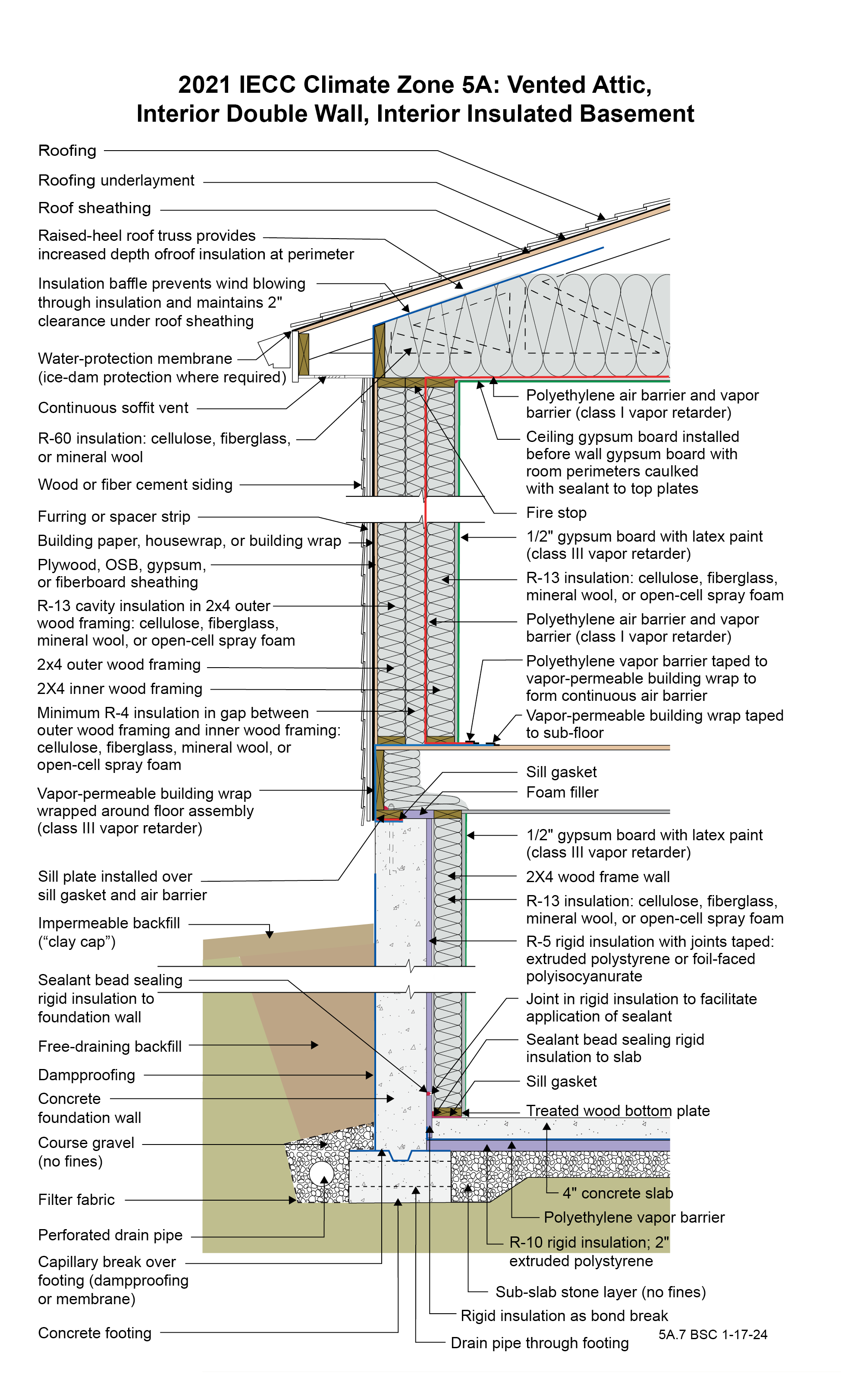
2021 IECC Climate Zone 5A: Vented Attic, Interior Double Wall, Interior Insulated Basement
Notes
Drawing 5A.7: IECC CZ 5: Vented Attic, Interior Double Wall, Interior Insulated Basement
- The function of the raised-heel roof truss is to control the temperature of the interior corner where the exterior wall meets the ceiling to control dust marking and mold. The minimum thermal resistance over the top of the wall assembly should match or exceed the thermal resistance of the wall assembly. Increasing the height of the raised heel can allow lower attic insulation levels by code. Per IECC 2021 Section R402.2.1, Ceilings with Attics, the ceiling insulation of this assembly can be R-49 rather than R-60 if the raised-heel roof truss is high enough to facilitate R-49 over the entire wall.
- A low-permeance roofing underlayment (less than 1 perm) is recommended for this roof type in this climate to reduce water diffusion through the underlayment to the sheathing.
- The ceiling gypsum board is installed prior to the wall gypsum board in order to accommodate a “filet” bead of sealant that seals the ceiling gypsum board to the top plates creating a continuous air control layer (“air barrier”) across the entire ceiling including interior partition walls. The gypsum board is the air control layer. The polyethylene at the ceiling is the vapor control layer.
- The gap between the exterior wall and the interior wall needs to be fire-stopped where the wall assemblies intersect the attic assembly. The gap between the outer wall framing and the inner wall framing can be increased to accommodate more insulation.
- Depending on interpretation, this assembly may not meet the 2021 IRC prescriptive requirements for vapor control. However, the assembly meets the intent of the code by keeping the first condensing surface above condensing temperatures. The first condensing surface within this assembly is the interior surface of the polyethylene vapor barrier inside the wall. More than half of the insulation in the assembly is to the outside of this surface, which helps it stay above condensing temperatures. The insulation on the outside of the polyethylene serves a similar purpose to the continuous insulation requirements in 2021 IRC Table R702.7(3).
- The rim joist is wrapped with a vapor-permeable building wrap to avoid installing a non-insulating vapor barrier on the exterior of the framing in a cold climate, as this could cause condensation. The rim joist building wrap should be overlapped and taped to the polyethylene vapor barrier to form a continuous air barrier.
- The typical sequence of construction to create this continuous air barrier requires building the inner wall portion of the double wall after the outer walls and roof system have been installed. Frame the inner walls on the floor and attach the polyethylene vapor barrier to the outside of the wall while it is still flat on the floor (before standing the wall up). By leaving enough extra polyethylene at the top, bottom, and sides of the wall, it can wrap around the ends of the wall to connect to the other air and vapor barriers by taping. It may be easier to install the polyethylene on the inside of the outer wall instead of the outside of the inner wall, but this arrangement may not control condensation, as there will be less insulation to the outside of the vapor barrier.
- The R-5 rigid insulation on the interior of the concrete foundation wall is required to control condensation within the interior frame wall as there is no interior vapor barrier on the interior of the frame wall – there is a Class III vapor “retarder” (semi-permeable latex paint). The reason that there is no interior vapor barrier on the interior of the frame wall is to permit drying to the interior. Additionally, the R-5 rigid insulation on the interior of the concrete foundation wall reduces the rate at which moisture contained in newly placed concrete moves to the interior.
- The vertical “short” strip of rigid insulation where the basement concrete slab intersects the exterior concrete basement wall has two lines of continuous sealant. The first seals the concrete slab edge to the interior surface of the vertical strip. The second seals the top back corner of the vertical strip to the concrete foundation wall. The two seals provide air control layer continuity between the concrete slab and the concrete wall to control radon and other soil gases.
- Horizontal insulation on the underside of the concrete floor slab is provided for comfort reasons and to control dust mites in carpets by reducing the relative humidity within the carpets.
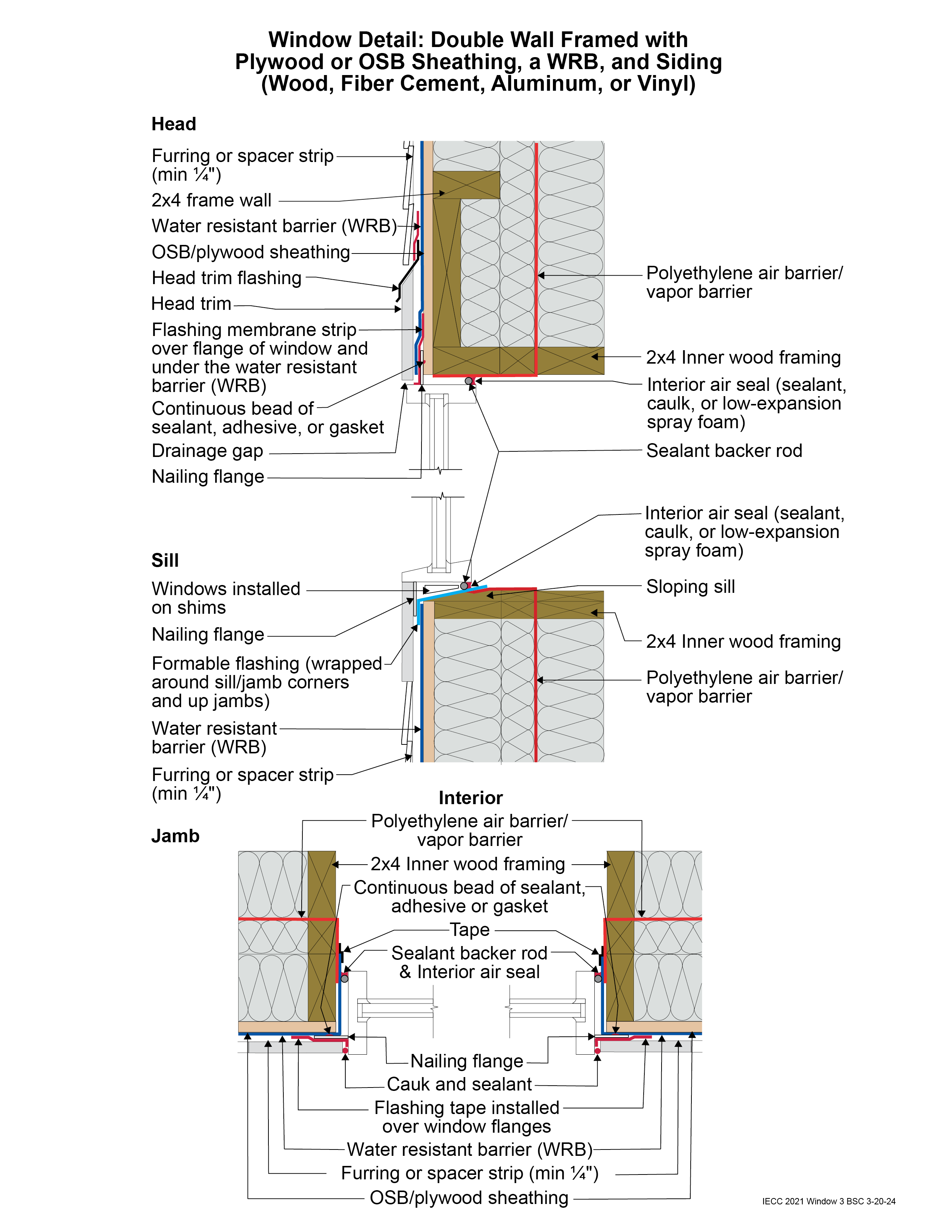
2021 IECC Window Detail: Double Wall Framed with Plywood or OSB Sheathing, a WRB, and Siding (Wood, Fiber Cement, Aluminum, or Vinyl)
Notes
Window Detail 3 - Double Wall Framed with Plywood or OSB Sheathing, a WRB, and Siding (Wood, Fiber Cement, Aluminum, or Vinyl)
- Note: Always follow the window manufacturer’s installation guidance. Not following manufacturer guidance may void the warranty.
- This is a “drained wall.” Drainage occurs between the siding and the water control layer or water-resistant barrier (WRB) in the gap created by furring installed vertically over the water control layer (WRB) at stud locations.
- The window openings are drained to the water control layer (WRB).
- The rough opening at the window sill is sloped and flashed with a formable flashing. The formable flashing is wrapped around the sill/jamb corners and at least part way up the jambs.
- The upper portion of the head trim flashing goes under the furring and is taped directly to the WRB with flashing tape. The furring is “cut through” by the head trim flashing, so that the furring below the flashing (behind the head trim) is separate from the furring above the flashing (behind the siding). During construction, the head trim is installed first on short pieces of furring. It is flashed directly to the WRB as described above. The rest of the furring is installed with the siding.
- Note the gap between the head trim and the top of the window assembly frame. This gap allows water to drain and allows the bottom of the trim to dry out more easily. If installed without this gap, capillary action can draw water into the tight space between the head trim and the window assembly frame. Note also the gap between the siding and the head trim flashing, which serves the same purposes.
- Consider installing rigid head flashing (rigid head flashing is not shown in the schematic). Rigid head flashing is similar to the head trim flashing shown in the schematic, but it goes over the top of the window frame instead of over the head trim. This is required by some manufacturers. It should be installed against the head nailing flange and over the top of the window frame. The vertical and horizontal portion of the flashing should be sealed directly to the window frame and flange with sealant. The red flashing membrane strip shown overlapping the head nailing flange in the schematic would now overlap the rigid head flashing. Use rigid head flashing with a drip edge to guide water away from the window assembly.
- Backer rod for the interior air sealant should be installed after the window is installed, leveled, and shimmed. Use the correct size backer rod.