Drawings
2021 IECC Climate Zone 4C: Vented Attic, 2x4 wall with Exterior Insulation, Basement with Interior and Exterior Insulation
Notes
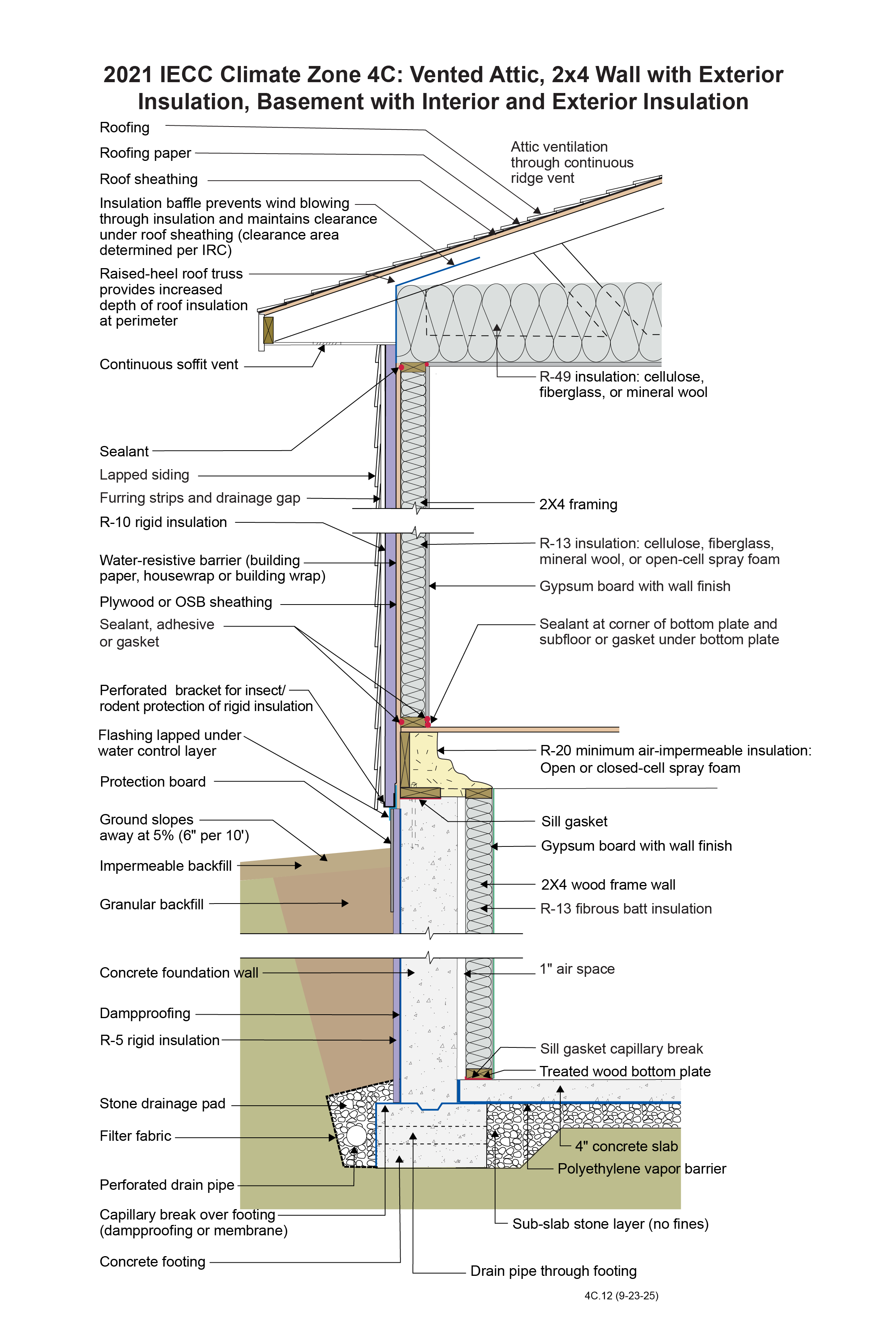
IECC Climate Zone 4C: Vented Attic, 2x4 Wall with Exterior Insulation, Basement with Interior and Exterior Insulation
- Full depth of R-49 insulation to be maintained over top plate of exterior wall in order to allow for the reduction from the R-60 requirement.
- Blocking and baffles to be installed to prevent wind-washing and disturbance of attic insulation at eaves.
- Ceiling materials at the attic floor should be air sealed at joints and penetrations to form a robust air barrier.
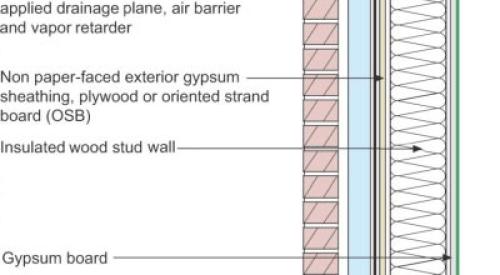
- The water-resistive barrier (WRB) is shown installed between the continuous insulation and the wall sheathing. Alternatively, the WRB can be on the exterior of the continuous insulation. In either case, all flashing details must ensure water is directed to the outside of the WRB.
- The R-10 rigid insulation on the exterior of the wall framing allows the wall to be constructed without an interior vapor barrier according to the provisions in Section R702.7 of the 2021 International Residential Code. To maximize drying potential in the wall assembly, the interior side of this wall assembly should not have a Class I vapor retarder.
- Rim joist insulation should align with R-value requirements for above-grade exterior walls.
- Exterior cladding fastening requirements should follow guidelines from cladding manufacturer or Section R703.15 of the 2021 IRC.
- A capillary break should be installed on top of footing prior to setting of wall forms and should consist of a liquid or membrane to prevent wicking of soil moisture into the foundation wall.
- Do not install a vapor retarder on the interior or exterior side of the framed wall in the basement. This is to allow for drying in the insulated wall assembly.
- Backfill placement should prevent damage to exterior continuous insulation.
- The air gap between the interior framed wall and the foundation wall ensures a capillary break between the foundation wall and the interior wall assembly.
- Exterior insulation should be protected above grade.
2021 IECC Window Detail: Framed Wall with Plywood or OSB Sheathing, a WRB, Thick Rigid Insulation, and Siding (Wood, Fiber Cement, Aluminum or Vinyl)
Notes
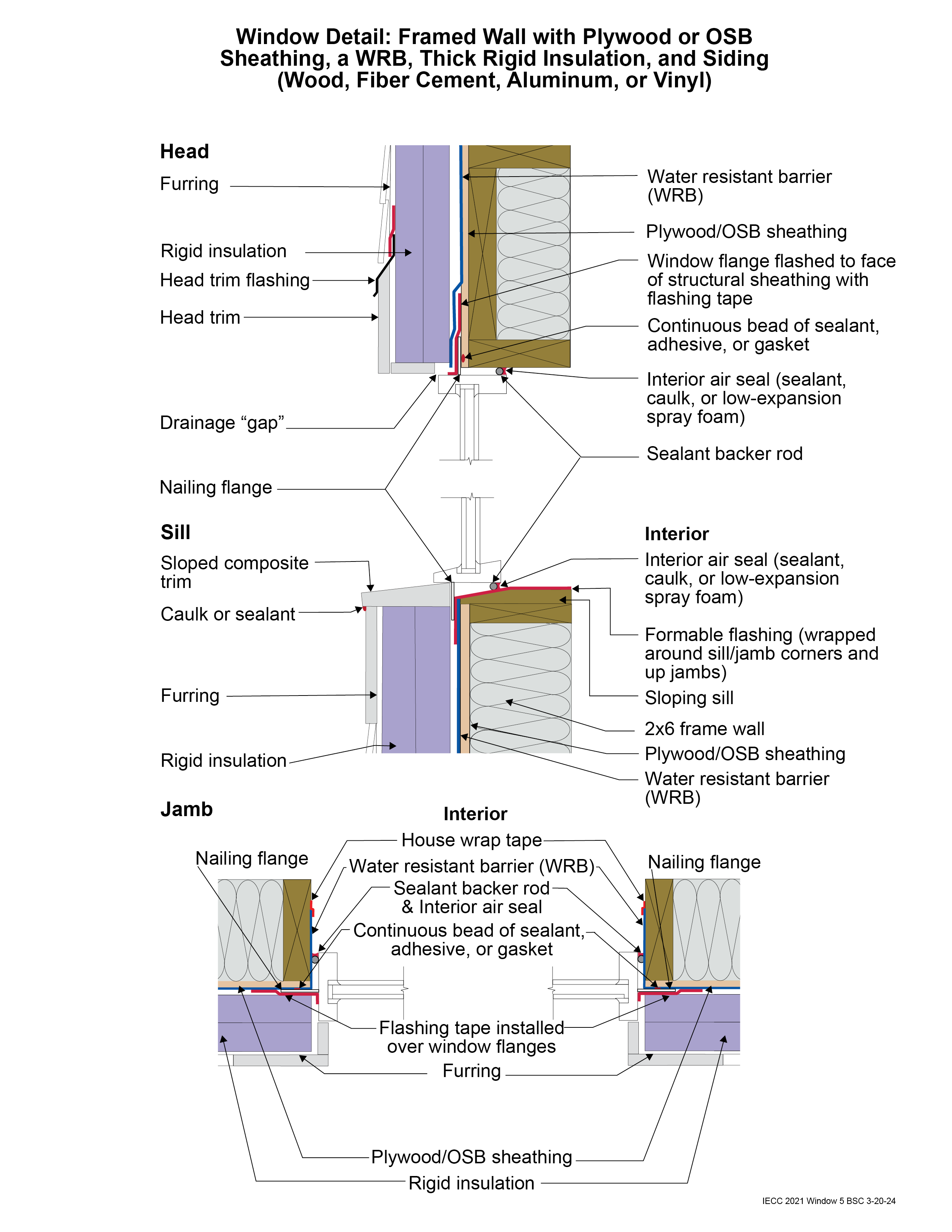
Window Detail 5 - Framed Wall with Plywood or OSB Sheathing, a WRB, Thick Rigid Insulation, and Siding (Wood, Fiber Cement, Aluminum or Vinyl)
- Note: Always follow the window manufacturer’s installation guidance. Not following manufacturer guidance may void the warranty.
- This is a “drained wall”. Drainage occurs outside of the water resistive barrier (WRB) installed over the structural sheathing. A drainage gap between the WRB and the rigid insulation is created by installing “cap nails” which act as a spacer.
- Drainage also occurs between the siding and the exterior face of the rigid insulation. A drainage gap is provided by furring installed vertically over the exterior face of the rigid insulation at stud locations.
- The window openings are drained to the exterior face of the WRB.
- The rough opening at the windowsill is sloped and flashed to the WRB with a formable flashing.
- The upper portion of the head trim flashing goes under the furring and is taped directly to the rigid foam with flashing tape. The furring is “cut through” by the head trim flashing, so that the furring below the flashing (behind the head trim) is separate from the furring above the flashing (behind the siding). During construction, the head trim is installed first on short pieces of furring. It is flashed directly to the rigid foam as described above. The rest of the furring is installed with the siding.
- With thick rigid foam installed on the exterior, providing nailing surfaces for trim and siding can be a challenge. Furring strips are one approach to accomplish this. Depending on configuration, some additional structural wood may be needed around the windows to accommodate trim.
- Note the gap between the head trim and the top of the window assembly frame. This gap allows water to drain and allows the bottom of the trim to dry out more easily. If installed without this gap, capillary action can draw water into the tight space between the head trim and the window assembly frame. Note also the gap between the siding and the head trim flashing, which serves the same purposes.
- Consider installing rigid head flashing (rigid head flashing is not shown in the schematic). Rigid head flashing is similar to the head trim flashing shown in the schematic, but it goes over the top of the window frame instead of over the head trim. This is required by some manufacturers. It should be installed against the head nailing flange and over the top of the window frame. The vertical and horizontal portion of the flashing should be sealed directly to the window frame and flange with sealant. The red flashing membrane strip shown overlapping the head nailing flange in the schematic would now overlap the rigid head flashing. Use rigid head flashing with a drip edge to guide water away from the window assembly.
- Backer rod for the interior air sealant should be installed after the window is installed, leveled, and shimmed. Use the correct size backer rod.