

Scope
Duct Quality Installation
Quantity and location of supply and return duct terminals match contractor balancing report.
- Verify ducts are located where specified on the balancing report
- Verify the number of ducts match the balancing report.
Description
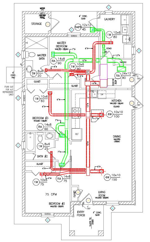
A duct layout schematic that identifies design airflow for each register like the one shown in Figure 1 may be useful during the test. Any location changes or deviations from the plan can be noted on the schematic.
How to Verify the Quantity and Location of Supply and Return Duct Terminals Match Contractor Balancing Report:
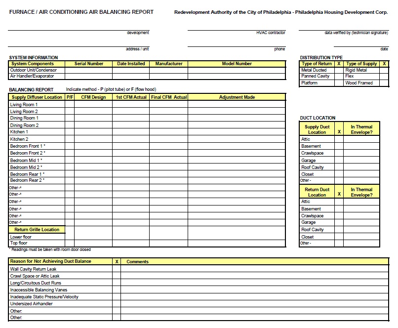
- The HVAC installer prepares a balancing report that identifies the room location and design airflow for each supply and return register. (See an example of a balancing report form in Figure 2.)
- The HVAC installer measures final individual room airflows using ANSI/ACCA 5 QI-2007 protocol and documents findings on the balancing report.
OR
The HERS rater measures final individual room airflows using RESNET Standard Section 804.2 and documents findings on the balancing report. The rater uses the powered flow hood (804.2.1) or the "bag inflation method" (804.2.2).
Ensuring Success
In homes with a central air handler and ducts, the HERS rater should inspect to verify that the quantity and location of supply and return duct terminals match the contractor’s balancing report.
Region
No climate specific information applies.
Compliance
To meet ENERGY STAR Certified Homes (Version 3.0, Revision 07) guidelines, the HVAC installer must provide the rater with a balancing report indicating the room name and design airflow for each supply and return register. See Contractor-Prepared Balancing Report Collected by Rater. Final individual room airflows should be measured and documented on the balancing report. These can be measured by the contractor (as noted in the link above) using ANSI/ACCA 5 QI-2007 protocol, and documented by the contractor on the balancing report and verified by the contractor to be within the greater of ± 20% or 25 CFM of design airflow. See the HVAC System Quality Installation Contractor Checklist, Air Balance.
Or, These can be measured by the rater using Section 804.2 of the Mortgage Industry National HERS (RESNET) Standard, documented by the rater and verified by the rater to be within the greater of ± 20% or 25 CFM of design airflow [as noted in HVAC/R 1.4.2 and HVAC/C 10.1.2]. Section 804.2 of the RESNET Standards states, when the rater verifies airflows, only a powered flow hood (804.2.1) or the "bag inflation method (804.2.2) can be used.
More Info
References and Resources
*For non-dated media, such as websites, the date listed is the date accessed.
Questions? Comments? Contact our webmaster.