Injected Spray Sealant for Existing HVAC Ducts

    Scope
    Scope Images
    Image
    The duct sealing spray injection system includes a blower/heater (background) and the sealant injection unit (foreground)
    Scope

    Thoroughly air seal HVAC ducts to ensure delivery of all air from a home’s central HVAC air handler to the supply grille terminations without air leakage. For aerosol spray sealant applications, follow the directions of the system supplier; typically this work will be done by a factory-authorized technician. For manual duct sealing of portions of the duct system not treated by the injected spray sealant system, follow the scope described below.

    Contractor Requirements

    Rebuild or repair all supply and return (if any) ducts using compatible materials to prevent air leakage according to the following procedure and in compliance with all manufacturer instructions:

    1. For retrofits, sealing/replacement will be limited to areas that are accessible without removing/breaching gypsum wall or ceiling boards.
    2. For new or existing ducts, determine type of ducts in the home.
    3. Gain access to the joints and duct connections that will not be treated by the injected spray sealant system, including:
      1. plenum connections
      2. air-handler cabinet to plenum
      3. plenum to take-off connections
      4. boot to duct connections
      5. boot- to-floor/ceiling connections.
    4. Prepare ducts/connections for sealing. For mastic or tape-based sealant, prepare the surface for work according to product specifications (e.g., remove old tape, oil, and debris) in order to receive new sealant.
    5. Seal all accessible ducts/connections listed above with:
      1. pliable, water-based sealant labeled as meeting UL-181 standards, or
      2. foil or mastic HVAC tape labeled as meeting UL-181 standards, and
      3. boot- to- floor/ceiling connections shall be sealed with silicone caulking, pliable mastic or other sealant
    6. Replace damaged ducts or sections of ducts where it is more cost effective to replace than repair and air seal.
    7. Repair or replace duct insulation as needed where accessible. New duct insulation shall be R-8. Repaired or replaced duct insulation shall have a complete vapor retarder.
    8. Clean up all debris from duct sealing and replace any disturbed insulation.
    9. Clean any work-related debris, dirt, dust, etc. from within the living space.

    See the Compliance Tab for related codes and standards requirements, and criteria to meet national programs such as DOE’s Zero Energy Ready Home programENERGY STAR Single-Family New Homes, and Indoor airPLUS.

    Description
    Description

    Air-tight ductwork is important to prevent energy loss, provide comfort, and avoid unwanted pressure imbalances that can result from air leaking outside a home’s thermal envelope. Ideally, all air moved by the air handler should arrive at the supply grille terminations without air leakage, and all air entering the return duct grilles should arrive back at the air handler without leakage. Duct sealing is important for new construction and older homes. Often older duct systems are quite leaky. Remedial duct sealing can dramatically improve the performance of a home’s HVAC system.

    Duct sealing with an injected aerosolized acrylic sealant is an effective way to eliminate duct leakage, when combined with manual sealing of other easily accessible areas. Other retrofit products for sealing ducts from the inside include commercially available spray-on coating products. 

    The acrylic sealant is injected into pressurized supply and return ducts. Sealant particles accumulate at leakage locations, gradually closing the leak. Gaps larger than 5/8 in. are recommended to be sealed manually with fiberglass mesh tape and mastic, and the duct material must have an interior air barrier. See more information about the aerosolized acrylic sealant process. The injection system continuously measures airflow and leakage throughout the sealing process and the process is halted when the leakage has been reduced to the desired level. The connections from the duct system to the air handler as well as to registers are blocked off to prevent the sealant from fouling HVAC equipment or escaping into the living space.

    The sealant injection system will typically measure total duct leakage of the system that the sealant is treating; however, in order to measure duct leakage to the outside for the entire system (including air handler, returns, and at registers) a separate duct leakage test would need to be conducted.

    The spray sealant system treats the ductwork; however, because the registers and air handler are blocked off, it does not seal leaks in the return, air handler, or at the junction between registers and finish surfaces (wall/ceiling/floor). These areas must be sealed by hand, which is possible because they are usually accessible.

    Injected spray sealant is less suitable for sealing systems to less than 40 to 60 CFM of leakage. A minimum airflow speed is necessary to keep the sealant suspended in the airstream. When leakage gets below 40 to 60 CFM, the flow becomes too low and the system may no longer function properly.

    High ambient relative humidity also complicates application. The sealant needs to enter the duct system “dry”; i.e., a skin should form around each droplet of sealant. This is accomplished by passing the sealant through a heated 8 to 10 ft. plastic tunnel prior to entry into the duct system. Under humid conditions, the sealant needs more time in the tunnel to dry out, requiring slower airflow or a longer tunnel.

    Connecting the sealant injection system to supply ductwork can be challenging for small homes or cramped areas, or where clearance between the top of the air handler heating coil and the ceiling is small. In some cases, a portion of the equipment may need to be placed out of doors, which can be difficult in inclement weather.

    Isolating the space conditioning equipment from the duct system is crucial to avoiding damage to that equipment. At times, this can be a challenge. Finally, whenever technology replaces manual methods, the possibility of equipment failure arises that can delay or halt a job.

    Materials

    The vendors of the injected spray sealant system will provide all equipment and materials necessary for its use; however, the following additional materials are needed for the manual sealing portion of the project:

    • pliable, water-based sealant labeled as meeting UL-181 standards, or
    • foil or mastic HVAC tape labeled as meeting UL-181 standards, and
    • silicone caulk
    • fiberglass mesh tape to reinforce mastic for large gaps
    • rags and cleaning supplies to remove dirt and dust from duct surfaces to be sealed
    • hand tools for removing and replacing register covers.

    Who Does the Work

    Most local codes will require a licensed HVAC contractor to perform this work.

    How-to Seal Ducts with an Injected Spray System

    Note steps involving the spray sealant injection system will be conducted by a factory-authorized installer.

    1. Assemble the spray sealant injection system.
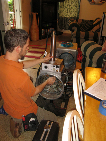
      A technician assembles the spray sealant injection system to seal HVAC ducts from the inside.
      Figure 1. A technician assembles the spray sealant injection system to seal HVAC ducts from the inside. (Source:  ARIES.)
    2. Block off registers so sealant does not enter living space. The air handler connection to the supply and return ducts must also be blocked off to prevent sealant from fouling the mechanical equipment.
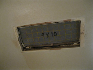
      Block off registers before installing spray sealant in HVAC ducts.
      Figure 2. Block off registers before installing spray sealant in HVAC ducts. (Source:  ARIES.)
    3. Connect the plastic application tunnel from the injection equipment (Figure 3) to the supply plenum (Figure 4). The assembled injection system includes a blower/heater-background, and the sealant injection unit-foreground (Figure 5).
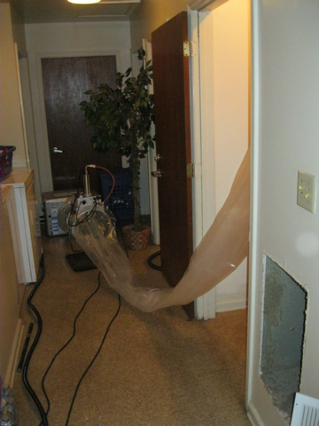
      Connect the plastic application tunnel to the injection equipment.
      Figure 3. Connect the plastic application tunnel to the injection equipment. (Source:  ARIES.)
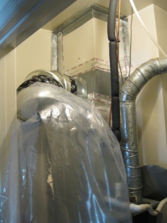
       
      Connect the plastic application tunnel from the injection equipment to the supply plenum.
      Figure 4. Connect the plastic application tunnel from the injection equipment to the supply plenum. (Source:  ARIES.)
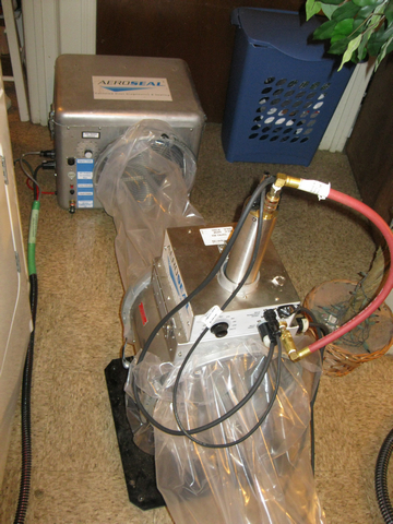
       
      The duct sealing spray injection system includes a blower/heater (background) and the sealant injection unit (foreground).
      Figure 5. The duct sealing spray injection system includes a blower/heater (background) and the sealant injection unit (foreground). (Source:  ARIES.)
    4. Turn on the spray injection system. The tunnel inflates as the injection system operates. Software tracks the sealing progress and controls the airflow.
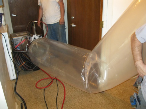
      The duct sealing spray injection system application tunnel inflates as the injection system operates.
      Figure 6. The duct sealing spray injection system application tunnel inflates as the injection system operates. (Source: ARIES.)
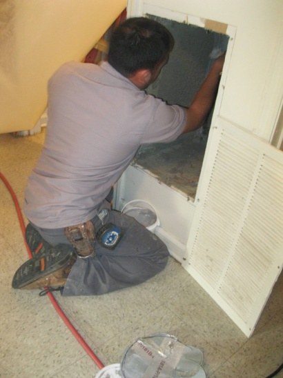
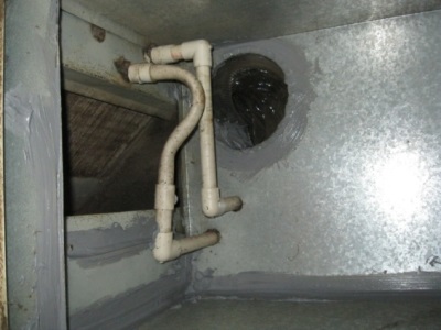
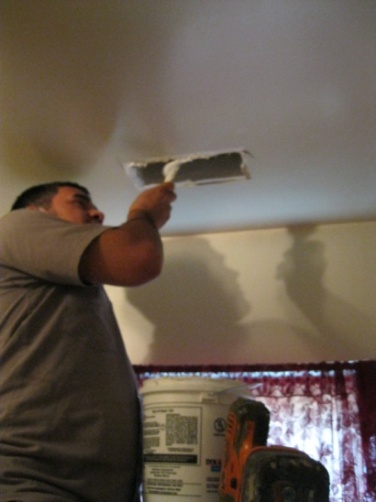
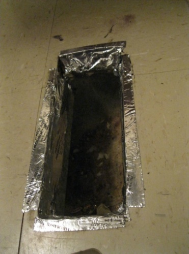
    5. Perform additional manual sealing. (These steps can be done by the vendor technician or other trades selected by the builder.) Seal around the opening to the supply plenum, seams in the return plenum, around the registers, and seams in the air handler box with mastic and/or foil tape. 
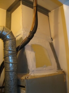
    Manually seal around the supply plenum.
    Figure 7. Manually seal around the supply plenum. (Source: ARIES.)


    Manually seal seams in the return plenum.
    Figure 8. Manually seal seams in the return plenum. (Source:  ARIES.)


    Manually seal around the return plenum.
    Figure 9. Manually seal around the return plenum. (Source: ARIES.)


    Manually seal around ceiling registers with mastic.
    Figure 10. Manually seal around ceiling registers with mastic. (Source:  ARIES.)


    Manually seal around ceiling registers with foil tape.
    Figure 11. Manually seal around ceiling registers with foil tape. (Source:  ARIES.)


    Manually seal seams in the air handler box with foil tape.
    Figure 12. Manually seal seams in the air handler box with foil tape. (Source:  ARIES.)


    Success
    Ensuring Success

    Before and after sealing, duct leakage testing can be used to verify proper implementation and quantify the improvement. If the system was extremely leaky, duct sealing may result in significantly greater volumes of air being delivered to spaces. Rebalancing of the system is recommended in these cases so as not to over-heat or over-cool rooms.

    Usually duct sealing will reduce the risk of combustion safety problems such as back-drafting; however, the effects of duct sealing on combustion appliances and venting should be tested to confirm the tighter ducts do not negatively alter the pressure dynamics of the home to create such problems.


    Climate
    Climate

    Ducts should be sealed in all climate zones. The more extreme the climate (either hot or cold) the greater the benefit from duct sealing will be realized.

    Training
    Right and Wrong Images
    Image
    WRONG – Duct is pulling away from floor because it is not sealed to floor
    WRONG – Duct is pulling away from floor because it is not sealed to floor
    Image
    WRONG – Duct is pulling away from ceiling because it is not sealed to the ceiling
    WRONG – Duct is pulling away from ceiling because it is not sealed to the ceiling
    Image
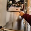
    Wrong - HVAC metal cabinet seam is not sealed with mastic or metal tape.
    Wrong - HVAC metal cabinet seam is not sealed with mastic or metal tape.
    Image
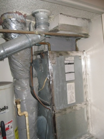
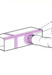
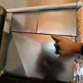
    Wrong - HVAC rigid metal duct seam needs top be air sealed with mastic or metal tape.
    Wrong - HVAC rigid metal duct seam needs top be air sealed with mastic or metal tape.
    Compliance

    Compliance

    The Compliance tab contains both program and code information. Code language is excerpted and summarized below. For exact code language, refer to the applicable code, which may require purchase from the publisher. While we continually update our database, links may have changed since posting. Please contact our webmaster if you find broken links.


    ENERGY STAR Single-Family New Homes, Version 3/3.1 (Rev. 11)

    National Rater Field Checklist

    HVAC System.
    6. Duct Quality Installation - Applies to Heating, Cooling, Ventilation, Exhaust, & Pressure Balancing Ducts, Unless Noted in Footnote.
    6.4 Rater-measured total duct leakage meets one of the following two options. Alternative in Footnote 40:39, 40, 41
    6.4.1 Rough-in: The greater of ≤ 4 CFM25 per 100 sq. ft. of CFA or ≤ 40 CFM25, with air handler & all ducts, building cavities used as ducts, & duct boots installed. All duct boots sealed to finished surface, Rater-verified at final.42
    6.4.2 Final: The greater of ≤ 8 CFM25 per 100 sq. ft. of CFA or ≤ 80 CFM25, with the air handler & all ducts, building cavities used as ducts, duct boots, & register grilles atop the finished surface (e.g., drywall, floor) installed.43
    6.5 Rater-measured duct leakage to outdoors the greater of ≤ 4 CFM25 per 100 sq. ft. of CFA or ≤ 40 CFM25.39, 44

    Footnote 39) Items 6.4 and 6.5 generally apply to the ducts of space heating, space cooling, and dwelling unit mechanical ventilation systems. However, visual inspection is permitted in lieu of testing for a dwelling unit mechanical ventilation system not connected to the space heating or space cooling system, regardless of the number of dwelling units it serves. In such cases, a Rater shall visually verify that all seams and connections are sealed with mastic or metal tape and all duct boots are sealed to floor, wall, or ceiling using caulk, foam, or mastic tape. For duct systems requiring testing, duct leakage shall be determined and documented by a Rater using ANSI / RESNET / ICC Std. 380 including all Addenda and Normative Appendices, with new versions and Addenda implemented according to the schedule defined by the HCO that the home is being certified under. Leakage limits shall be assessed on a per-system, rather than per-home, basis.

    Footnote 40) For a duct system with three or more returns, the total Rater-measured duct leakage is permitted to be the greater of ≤ 6 CFM25 per 100 sq. ft. of CFA or ≤ 60 CFM25 at ‘rough-in’ or the greater of ≤ 12 CFM25 per 100 sq. ft. of CFA or ≤ 120 CFM25 at ‘final’.

    Footnote 41) Note that compliance with Item 6.4.1 or 6.4.2 in conjunction with Section 4a of the National Rater Design Review Checklist automatically achieves Grade I total duct leakage per ANSI / RESNET / ACCA Std. 310.

    Footnote 42) Cabinets (e.g., kitchen, bath, multimedia) or ducts that connect duct boots to toe-kick registers are not required to be in place during the ‘rough-in’ test.

    Footnote 43) Registers atop carpets are permitted to be removed and the face of the duct boot temporarily sealed during testing. In such cases, the Rater shall visually verify that the boot has been durably sealed to the subfloor (e.g., using duct mastic or caulk) to prevent leakage during normal operation.

    Footnote 44) Testing of duct leakage to the outdoors can be waived in accordance with the 2nd or 3rd alternative of ANSI / RESNET / ICC Std. 301, Table 4.2.2 (1), footnote (w). Alternatively, testing of duct leakage to outdoors can be waived in accordance with Section 5.5.2 of ANSI / RESNET / ICC Std. 380 if total duct leakage, at rough-in or final, is ≤ 4 CFM25 per 100 sq. ft. of conditioned floor area or 40 CFM25, whichever is larger. Guidance to assist partners with these alternatives, including modeling inputs, is available at http://www.energystar.gov/newhomesguidance.

    Please see the ENERGY STAR Single-Family New Homes Implementation Timeline for the program version and revision currently applicable in your state.


    DOE Zero Energy Ready Home (Revision 07)

    Exhibit 1 Mandatory Requirements.
    Exhibit 1, Item 1) Certified under the ENERGY STAR Qualified Homes Program or the ENERGY STAR Multifamily New Construction Program.


    2009, 2012, 2015, 2018, and 2021 International Energy Conservation Code (IECC)

    Section R403.2.2 (R403.3.2 in 2015 and 2018 IECC and R403.3.4 in 2021 IECC) Sealing (Mandatory). All joints and seams of air ducts, air handlers, and filter boxes are substantially airtight by means of tapes, mastics, liquid sealants, gasketing or other approved closure systems.

    Retrofit:  2009, 2012, 2015, 2018,  and 2021 IECC

    Section R101.4.3 (in 2009 and 2012). Additions, alterations, renovations, or repairs shall conform to the provisions of this code, without requiring the unaltered portions of the existing building to comply with this code. (See code for additional requirements and exceptions.)

    Chapter 5 (in 2015, 2018, 2021). The provisions of this chapter shall control the alteration, repair, addition, and change of occupancy of existing buildings and structures.


    2009, 2012, 20152018, and 2021 International Residential Code (IRC)

    Section M1601.4.1 Joints and seams. Tapes, mastics, and fasteners are rated UL 181A or UL 181B and are labeled according to the duct construction. Metal duct connections with equipment and/or fittings are mechanically fastened. Crimp joints for round metal ducts have a contact lap of 1 inch minimum and are fastened with a minimum of three equally spaced sheet-metal screws. Exceptions: a) Joint and seams covered with spray polyurethane foam. b) Where a partially inaccessible duct connection exists, mechanical fasteners can be equally spaced on the exposed portion of the joint so as to prevent a hinge effect. c) continuously welded and locking-type longitudinal joints and seams on ducts operating at less than 2 in. w.g. (500 Pa).

    Retrofit:  2009, 2012, 2015, 2018,  and 2021 IRC

    Section R102.7.1 Additions, alterations, or repairs. Additions, alterations, renovations, or repairs shall conform to the provisions of this code, without requiring the unaltered portions of the existing building to comply with the requirements of this code, unless otherwise stated. (See code for additional requirements and exceptions.)

    Appendix J regulates the repair, renovation, alteration, and reconstruction of existing buildings and is intended to encourage their continued safe use.

    More

    More Info.

    Access to some references may require purchase from the publisher. While we continually update our database, links may have changed since posting. Please contact our webmaster if you find broken links.

    Case Studies
    References and Resources*
    Author(s)
    Building Science Corporation
    Organization(s)
    BSC
    Publication Date
    Description
    Brochure with details on HVAC duct air sealing.
    Author(s)
    Dentz Jordan,
    Conlin Francis,
    Holloway Parker,
    Podorson David,
    Varshney Kapil
    Organization(s)
    Advanced Residential Integrated Energy Solutions,
    ARIES,
    Levy Partnership,
    National Renewable Energy Laboratory,
    NREL,
    U.S. Department of Energy,
    DOE
    Publication Date
    Description
    Report describing two retrofit duct sealing techniques - manually-applied sealants and injecting a spray sealant, that were implemented in several low-rise multi-unit buildings in North Carolina.
    Organization(s)
    DOE
    Publication Date
    Description
    An article profiling the Building America research teams.
    *For non-dated media, such as websites, the date listed is the date accessed.
    Contributors to this Guide

    The following authors and organizations contributed to the content in this Guide.

    The Levy Partnership, Inc., lead for the ARIES Collaborative, a DOE Building America Research Team

    Sales
    Building Science Measures
    Building Science-to-Sales Translator

    Tight Duct Sealing =

    Image(s)
    Technical Description

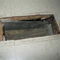
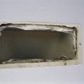
    As conditioned air flows from heating and cooling equipment to the spaces where people live, excessive leaks compromise comfort, health, and durability while increasing energy costs. This is because conditioned air escapes ducts supplying heating and cooling, and potentially contaminated air is pulled into the ducts, returning air to the heating and cooling equipment. Professionally sealed comfort delivery systems are significantly air-tight at all seams and connections. Sealing helps conditioned air get where it is needed, at the correct temperature, without pulling in contaminants from crawlspaces and attics.
    Sales Message
    Last Updated

    Did you find this information helpful?

    If you have questions and/or would like a reply to this feedback, please include your e-mail address in the message.
    This question is for testing whether or not you are a human visitor and to prevent automated spam submissions.