Scope
Install a filter with a MERV (Minimum Efficiency Reporting Value) rating of 6 or higher in each ducted heating and cooling system to filter air passing through the return air duct and any outdoor air that is mechanically supplied to the air handler.
- Design the HVAC system to adequately account for the pressure drop associated with higher MERV filters.
- Install the filter in a location where it can be easily accessed by the homeowner for cleaning or replacement when dirty.
- Depending on application, higher than MERV 6 may be recommended. DOE’s Zero Energy Ready Home program and the U.S. Environmental Protection Agency’s Indoor airPLUS program require that filters be at least MERV 8. MERV-13 or higher is recommended for control of viruses.
See the Compliance Tab for links to related codes and standards and voluntary federal energy-efficiency program requirements.
Description
Home heating, ventilation, and air-conditioning (HVAC) systems that have a central air handler and ducting should be equipped with air filters. The purpose of air filters is to remove particulates, such as dust, from the air stream. This serves three primary purposes:
- Filters improve indoor air quality for occupant respiratory health. This is key not only in daily life, but especially when outdoor air quality is low such as during extreme heat events or during regional wildfires.
- Filters protect the HVAC equipment from degradation by keeping internal components clean of particulate build-up that could cause lower equipment efficiency, reduced reliability, and diminished heat transfer.
- Filters help maintain a cleaner indoor environment by removing particulates that would otherwise settle on furniture and floors.
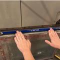
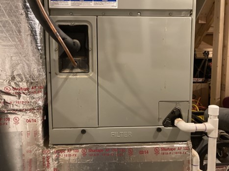
HVAC filters are typically located upstream of other components. This means they are usually in the return duct adjacent to the air handler or on the back of the return register grille(s). This allows them to trap particulates in the air pulled into the return ducts by the air handler, before the particulates reach the coils, fan, or supply ducting. Figure 1 shows the lower portion of a vertical upflow air handler for a heat pump. Return air flows down the return ducting (silver) installed to the left of the air handler. The air follows the duct work in a U-turn to enter the air handler from below. The first component the air contacts is the filter (notice the horizontal filter panel at the bottom of the unit). The heat pump coils are located above the filter, as indicated by the refrigerant lines (upper left) and condensate drainpipe (lower right). This configuration allows the filter to protect the rest of the system from debris and dust.
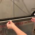
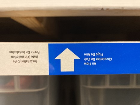
Filters must be installed in the correct orientation to work properly. Most commercial filters have an arrow on the edge of the filter indicating the direction of airflow when properly installed (Figure 2). If the filter in Figure 2 were to be installed in an upflow air handler (like the one shown in Figure 1), then the arrow should be facing upwards (even though the writing would be upside down in this case).
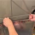
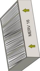
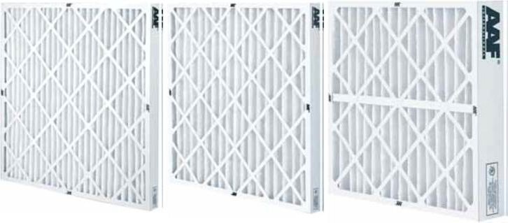
Filters are available in a range of styles, materials, and sizes. They’re generally one to four inches thick, made of polyester and/or fiberglass, and styled in a flat or pleated pattern (Figure 3).
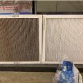
Filters use either mechanical filtration or electrostatic filtration to remove particulates from the air. Mechanical (i.e., surface media) filtration is the capture of particulates through a dense fiber medium. Typically, the filter media are pleated, which allows for more surface area to capture debris. Electrostatic filtration uses electrostatic precipitation to remove particulates. Some filter models on the market combine mechanical and electrostatic filtration. Filters can be replaceable or washable and reusable. Replacement filters are typically made of synthetic media or fiberglass. They should be replaced every three months or sooner if needed, especially if the HVAC equipment is used continually. Filters loaded with particulates should be thrown away. Washable filters typically use electrostatic filtration and are made of aluminum mesh or foam rubber. They should be removed for cleaning once every one to three months, rinsed with water or cleaning solution, air dried, and then re-installed. If washable air filters are not dried properly, they have the potential to harbor mold.
There are two elements of HVAC filter performance: (1) the effectiveness at removing particles from the air and (2) resistance to airflow (i.e., pressure drop) across the filter. The Minimum Efficiency Reporting Value (MERV) rating is one measure of a filter’s ability to capture particles sized from 0.3 to 10 micrometers (μm) from the air stream. It is measured by the test method in the ASHRAE 52.2 Standard. MERV rating corresponds to a level of performance ranging from 1 to 16 - the higher the MERV rating, the more effective a filter is at capturing particles passing through it. ENERGY STAR requires filters that are MERV 6 or higher, and DOE’s Zero Energy Ready Home program and EPA’s Indoor airPlus program require MERV 8 or higher. The EPA and the American Society of Heating, Refrigerating, and Air-conditioning Engineers (ASHRAE) recommend a minimum filter rating of MERV-13 for managing COVID-19 and other virus concentrations in a home (EPA 2023, ASHRAE 2023).
Another measure of a filter’s effectiveness at removing particles is particle size efficiency, which is the fraction (or percentage) of particles captured on a filter, as determined by the test method in AHRI Standard 680. Particle size efficiency is measured across three particle‐size bins: 0.3 to 1.0 μm, 1.0 to 3.0 μm, and 3.0 to 10.0 μm. The percentages correspond to MERV rating as shown in Table 1, which is based on the National Air Filtration Association’s Understanding MERV Guide and the U.S. Environmental Protection Agency’s (EPA) Residential Air Cleaners (Second Edition).
| MERV Filter Performance Characteristics | |||||
|---|---|---|---|---|---|
| MERV Rating | Composite Average Particle Size Capture Efficiency (%) in Size Range (µm) | Typical Applications | Typical Controlled Contaminants | ||
| Range E1: 0.3 - 1.0 µm | Range E2: 1.0 - 3.0 µm | Range E3: 3.0 - 10.0 µm | |||
| 1 | n/a | n/a | <20% | Minimal equipment protection in residential and light commercial applications | Pollen, dust mites, Spanish moss, carpet fibers, spray paint dust |
| 2 | n/a | n/a | <20% | ||
| 3 | n/a | n/a | <20% | ||
| 4 | n/a | n/a | <20% | ||
| 5 | n/a | n/a | >20% | Good equipment protection in residential applications, minimal equipment protection in commercial and industrial applications | All of the above, plus: mold spores, pet dander, hair spray, fabric protector, powdered milk |
| 6 | n/a | n/a | >35% | ||
| 7 | n/a | n/a | >50% | ||
| 8 | n/a | >20% | >70% | ||
| 9 | n/a | >35% | >75% | Superior equipment protection in residential applications, good equipment protection in commercial and industrial applications | All of the above, plus: Legionella, humidifier dust, lead dust, milled flour, auto emission particles |
| 10 | n/a | >50% | >80% | ||
| 11 | >20% | >65% | >85% | ||
| 12 | >35% | >80% | >90% | ||
| 13 | >50% | >85% | >90% | Healthcare and hospitals, superior equipment protection in commercial and residential applications | All of the above, plus: bacteria, cooking oil, most smoke, face powder, paint pigments |
| 14 | >75% | >90% | >95% | ||
| 15 | >85% | >90% | >95% | ||
| 16 | >95% | >95% | >95% | ||
The second aspect of HVAC filter performance is pressure drop or resistance to airflow. As the air stream passes through the filter, it decreases its velocity due to the resistance of the filter. This resistance is measured in inches of water column (IWC, or in. w.c.) at either a specific face velocity or airflow rate. The resistance to airflow of a new filter is called the “initial pressure drop,” whereas the resistance when the filter is loaded with particulates is called the “final pressure drop.” The contribution of the filter to the total system pressure drop is typically 20%-50%, depending on the system configuration, filter efficiency, and loading condition. HVAC system engineers and designers are supposed to take the initial pressure drop of the filter into account when determining how to size HVAC equipment and related ductwork for residential or commercial buildings.
The resistance to airflow in a high-static-pressure system causes the controls of brushless permanent magnet (BPM) blower motors to increase speed and power draw to maintain system airflow, resulting in an increase in energy consumption. Permanent split capacitor (PSC) blower motors do not have airflow controls like BPM blower motors and thus will not increase power and speed to maintain system airflow. Instead, since PSC blower motors cannot adjust speed or torque, airflow rates slow down in response to increasing system pressures. This results in a drop in power consumption as well. This is known as “fall off,” when the system pressure forces reduce airflow and power consumption. As a result, the run time necessary to cool or heat the ambient air to the thermostat’s set‐point temperature is extended, which can lead to an overall increase in energy use. In addition, excessive pressure drop can damage furnaces due to overheating, can freeze condensing coils in air conditioning units, and can burn out blower motors. It’s important for homeowners to purchase filters with a pressure drop performance that meets their HVAC system specifications to run their equipment efficiently and prevent damage. The Air Conditioning Contractors of America (ACCA) Manual D Residential Duct Systems offers guidance for sizing residential ducting systems, including sizing HVAC filters for pressure drop in the system.
Having a high MERV rating does not necessarily mean that a filter will have a higher pressure drop than one with a lower MERV rating. Pressure drop can be greatly reduced by the design of the filter, regardless of MERV rating. Filters with deeper pleats or an increased number of pleats tend to have lower pressure drop. Having a high number of pleats and/or deeper pleats increases the overall surface area of the filter media, which in turn lowers pressure drop without changing the MERV rating. For example, a filter that has 4-inch-deep pleats has twice as much surface area as a filter with 2-inch pleats. If a homeowner is requesting a very high MERV filter, it may require the alteration or replacement of ducting if the pressure drop of the filter is greater than the pressure drop allotted to the filter in the system design. Another option is to advise the homeowner to purchase separate air filtration equipment that can clean air without impacting the performance of the HVAC equipment.
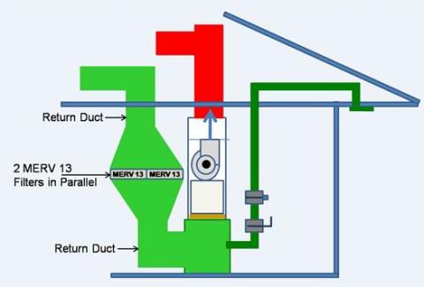
One option for reducing pressure drop involves modifying the return ductwork near the air handler or furnace to increase filter surface area. If the furnace is in a location where it can be accessed by the homeowner for filter replacement and where the furnace location permits an increase in the width of the return duct, the following approach may enable the installation of higher MERV filters.
- Calculate pressure drop and airflow requirements for the desired filter MERV rating and dimensions in accord with Manual D (ANSI/ACCA 2009).
- Construct a box to hold two filters side-by-side (or one larger filter) in the return duct above the 90-degree turn into the return air plenum.
- Increase the duct width to accommodate the filter dimensions above and below this filter box.
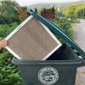
- If possible, install the filter box at shoulder height for easier servicing. See Figure 4.
Most residential HVAC systems operate efficiently when the total pressure drop across the system (including all the components) is no higher than 0.4 or 0.5 in. WC static pressure. The standard air handler with a permanent split capacitor (PSC) motor is capable of moving the required air flow at about 0.5 in. WC of pressure drop. A variable speed air handler with an electrically commutated (ECM) motor is most efficient when operating at low static pressures (0.3 to 0.5 in. WC).
If a filter with a pressure drop of 0.25 is used in an air handler with a PSC motor, the filter alone can use half of the system’s available static pressure. If a high MERV filter is installed without designing for it and the static pressure is increased to an amount much higher than the optimum, several negative consequences can result:
- The HVAC system’s overall efficiency (Seasonal Energy Efficiency Ratio or SEER) will go down.
- The equipment could malfunction or burnout. Motor burnout is more likely to occur with an ECM motor than with a PSC motor. A PSC blower motor will work up to about 0.5 in. WC, then it will “fall off,” i.e., the motor will stop pushing, although the fan will continue to turn. With an ECM, although it is most efficient at 0.3 inches of static pressure, it will continue to work if the static pressure goes up, even as high as 1 in. WC. The ECM will not fall off like a PSC motor; it will continue trying to meet the target cubic feet per minute (CFM) of air flow, but the fan motor will work harder and harder until it burns itself out.
- In hot, humid climates, if the pressure drop is too high across the filter (i.e., if the filter offers too much resistance), it slows down the air coming through the fan and decreases supply air speed so much that the air in the supply ducts gets too cold. If the ducts are located in a vented, hot, humid attic, the temperature differential is enough to drop the outside surface of the ducts below dewpoint, which can cause sweating on the ducts and eventually can cause the evaporator coil to ice up.
It should be noted that pressure drop through a high-MERV filter varies depending on the velocity of the air flow. Air filters with MERV ratings of 7 to 14+ can have pressure drops anywhere from 0.05 to 0.3 inches WC, depending on filter thickness and air flow velocity. For example, a 4-inch-thick MERV 12 filter can have a 0.2-inch WC pressure drop at a velocity of 300 feet per minute (FPM) and a 0.35-inch WC pressure drop at a velocity of 500 FPM (which is the maximum desired velocity for residential HVAC; 200 FPM to 400 FPM is preferred). The velocity across the filter depends on filter area; the velocity is an input in the Manual D calculation. Filter area can be increased by selecting filters with higher pleats or larger overall dimensions. This may be limited by the HVAC equipment purchased or may require in-field fabrication of a larger filter port on the air handler unit.
As illustrated in Figure 5 below, filter resistance varies by surface area. Deeper pleats or bigger filter dimensions add surface area. Three MERV 7 filters made by the same manufacturer can vary significantly in rated resistance:
- Filter A is a 1-inch-thick filter with 0.20-inch WC at 300 feet per minute (FPM) air flow velocity
- Filter B is a 2-inch-thick filter with 0.13-inch WC at 300 FPM
- Filter C is a 4-inch-thick filter with 0.12-inch WC at 300 FPM
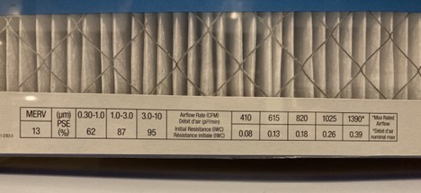
Not all manufacturers give specifications on their filters. Avoid purchasing filters from manufacturers who won’t provide static pressure measurements. Beginning April 1, 2019, the State of California required manufacturers to label HVAC filters with the MERV rating, particle size efficiency (across three particle size bins), and pressure drop (across five airflow rates, as applicable). The label either resides on the edge of the filter or on the pleats so consumers can readily access the information to purchase an appropriate replacement (Figure 6). Looking at Figure 6, the MERV rating of the filter is shown on the very left (MERV 13). Next to this is a table of particle capture efficiencies (e.g. in the particle size range of 0.30-1.0 μm, this filter has a 62% capture efficiency). On the right hand side is a table of pressure drops and associated airflow rates (e.g. this filter has a pressure drop of 0.08 IWC at and airflow rate of 410 CFM. To the very right is the maximum rated airflow for this filter (1,390 CFM). The highly pleated design of this filter allows it to achieve reasonable pressure drop at lower airflows given it’s high MERV rating and narrow profile (1 inch).
The accumulation of dirt and particles can greatly increase pressure drop across a filter. Making filters accessible for easy replacement and providing controls that tell homeowners when replacement is due will help to eliminate problems such as clogging and filter collapse, which are more likely to occur with higher MERV filters (Springer 2009). If exceptionally high filtration is desired (above MERV 13), some sources suggest using separate air filtration equipment with a HEPA filter that can clean the air without impacting furnace performance, although their functionality is localized as opposed to whole house (EPA 2009).
For more on HVAC filter installation, see the guide “Proper Installation of Furnace and Air-Handler Filters.”
How to Select a High MERV Filter
- Design (or require the HVAC contractor to design) the HVAC duct system using ACCA Manual D to determine the maximum static pressure that the filter can have and select a MERV 6 or higher filter within that limit. Adjust the duct size, duct length, and/or filter surface area as necessary to ensure that the total pressure drop across the system does not exceed the blower fan motor’s limit, given the size of the unit.
- After the HVAC equipment and filter are installed, measure the total static pressure of the system. With a manometer, measure the supply side with respect to ambient house pressure, measure the return side with respect to ambient house pressure, then add both numbers together. The result should equal no more than 0.4 or 0.5 inches w.c.
Success
In homes with ducted HVAC equipment, the HVAC designer should specify HVAC systems with filters that are rated MERV 6 or higher and ensure that the HVAC system can accommodate the pressure drop associated with higher MERV filters. When certifying ENERGY STAR Single-Family New homes, the HERS rater should inspect to make sure that MERV 6 or higher filters are installed. When assessing EPA Indoor airPLUS and DOE Zero Energy Ready certified homes, the rater should verify that MERV 8 or higher filters are installed in. For homes or areas needing to address COVID-19 or other virus concentrations, MERV-13 or higher is recommended.
Ozone generators are sometimes marketed as air cleaners. Research has shown that these devices are not safe or effective in removing pollutants. Ozone is a lung irritant that can cause adverse health effects. Ozone can mix with other chemicals in the environment to produce harmful byproducts. More information on ozone generators sold as air cleaners and the health risks of ozone can be found at EPA's Indoor Air Quality website.
Climate
No climate-specific information applies.
Training
Compliance
Retrofit
SCOPE
Replace the air filters in ducted heating, ventilation and air-conditioning (HVAC) equipment with new filters having a MERV rating of 6 or higher and a resistance to airflow that does not exceed the allowable pressure drop for the HVAC system.
- Check the condition of the existing HVAC filters. If the filters are loaded with particulates, replace with new, higher MERV filters when performing HVAC-related home performance upgrades and when responding to comfort complaints. Make sure the new filters do not exceed the allowed pressure drop for the HVAC system.
- If the homeowner requests a high-MERV (or HEPA) filter, verify the pressure drop will still be within acceptable limits.
- Provide homeowners with information for future filter replacement, such as the date of the next filter replacement, designed pressure drop for the filter, and installation instructions.
- Follow safe work practices as described in the U.S. Department of Energy’s Standard Work Specifications when replacing and handling HVAC filters and inspecting air handlers.
DESCRIPTION
How to Install and Specify High-MERV Filters in an Existing Home
- At the HVAC equipment, identify the return grille label, if available. Write down the initial resistance (inches water column, inch w.c.) of the HVAC filter at the design airflow rate (cubic-feet per minute, cfm).
- Go to each HVAC filter location and write down the dimensions of the existing filters. If there are air gaps around any of the filters, then use a measuring tape to determine the appropriate dimensions.
- When purchasing or ordering new HVAC filters, use the resistance-to-airflow specified on the return grille label to purchase a replacement with the appropriate resistance-to-airflow. If the return grille label doesn’t exist and specified filter resistance-to-airflow for the HVAC equipment is unavailable, try to determine the resistance-to-airflow of the spent filter (either on the filter, or via internet or retail salesperson). If no information is available for the resistance-to-airflow, consider purchasing the same or a similar model of HVAC filter as the spent filter. Use the filter dimensions you’ve written down to ensure the replacement is the proper size. Identify filters with a MERV rating of 6 or higher. If possible, select a filter with the static pressure measurements listed on the packaging or online.
- Once you’ve acquired new HVAC filters, note the installation date and recommended replacement date on the edge with permanent marker so the homeowner can track the replacement cycle. Also note the MERV level and the specified air filter resistance-to-airflow if these are not already printed on the filter.
- Turn off the HVAC equipment or set the thermostat so it won’t operate while replacing the filters.
- Remove the spent filters from the ducted HVAC equipment.
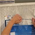
- When installing the new HVAC filters, remove the plastic wrap but do not remove the cardboard framing. Identify the airflow arrow and align the filter so the arrow points toward the HVAC equipment in the return duct or return register grille.
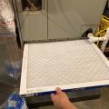
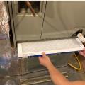
- Insert the HVAC filter into the designated slot.
- Restore any levers, gaskets, seals, or grilles to their appropriate condition.
- Turn the HVAC equipment back on or return the thermostat to the appropriate temperature.
- Contractors, show homeowners how to replace their HVAC filters and advise that they be replaced every three months, or more often if needed, especially in homes with HVAC equipment that runs six to twelve months per year, with four or more occupants, with pets, smoking indoors, occupants with allergies, or if construction is taking place within or outside the home. Show the homeowner the installation date and recommended replacement date noted on the filter frame.
- Contractors, advise homeowners to check HVAC filters periodically. Filters should be replaced immediately if the filters are clogged with debris, have collapsed fins, are making a banging noise when the system comes on, or are damp or moldy.
- For homeowners who desire or require HEPA level filtration - a HEPA filter will typically add too much pressure drop if placed in the main return register. A bypass can be installed between the supply and return plenums to filter a portion of the air through the HEPA filter as the system operates. Alternatively, an independent, free-standing HEPA filter system can be located in a room in the home, for example, a bedroom where the affected occupant spends most of their time while at home. Another alternative is to install an electronic air cleaner (EAC). There are several on the market based on various technologies such as electrostatic precipitators or ultraviolet light based systems. The EPA recommends against using ozone generators because ozone is a lung irritant (Guide to Air Cleaners).
COMPLIANCE
See Compliance tab.
More
More Info.
Access to some references may require purchase from the publisher. While we continually update our database, links may have changed since posting. Please contact our webmaster if you find broken links.
The following authors and organizations contributed to the content in this Guide.
Sales
High-MERV Filter = High Capture Filter
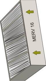
Furnace filters can clean indoor air by trapping dust, pollen, mold spores, pet dander, and other indoor air contaminants. Air filter efficiency is defined in MERVs, or “Minimum Efficiency Reporting Value.” A typical 1-inch-thick spun fiberglass furnace filter has a rating of 1 to 4 on the MERV scale and can trap only large particles like sawdust, carpet fibers, dust mites, and pollen. High capture filters like those specified for Indoor airPLUS Certified Homes must be at least MERV 8. These filters can remove most cement dust, mold spores, animal dander, hair spray, and even smaller particles from air. Even higher MERV levels are available including HEPA filters with MERV ratings from 17 to 20 that can filter out particles smaller than 0.3 microns, including viruses. However, higher MERV filters restrict airflow. As a result, heating and cooling system air handlers need to be designed to for a filter size that meets air flow requirements.
