Showing results 2751 - 3000 of 4973
Image
Image
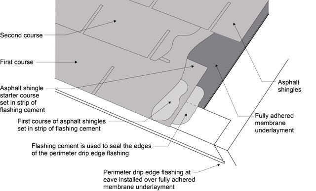
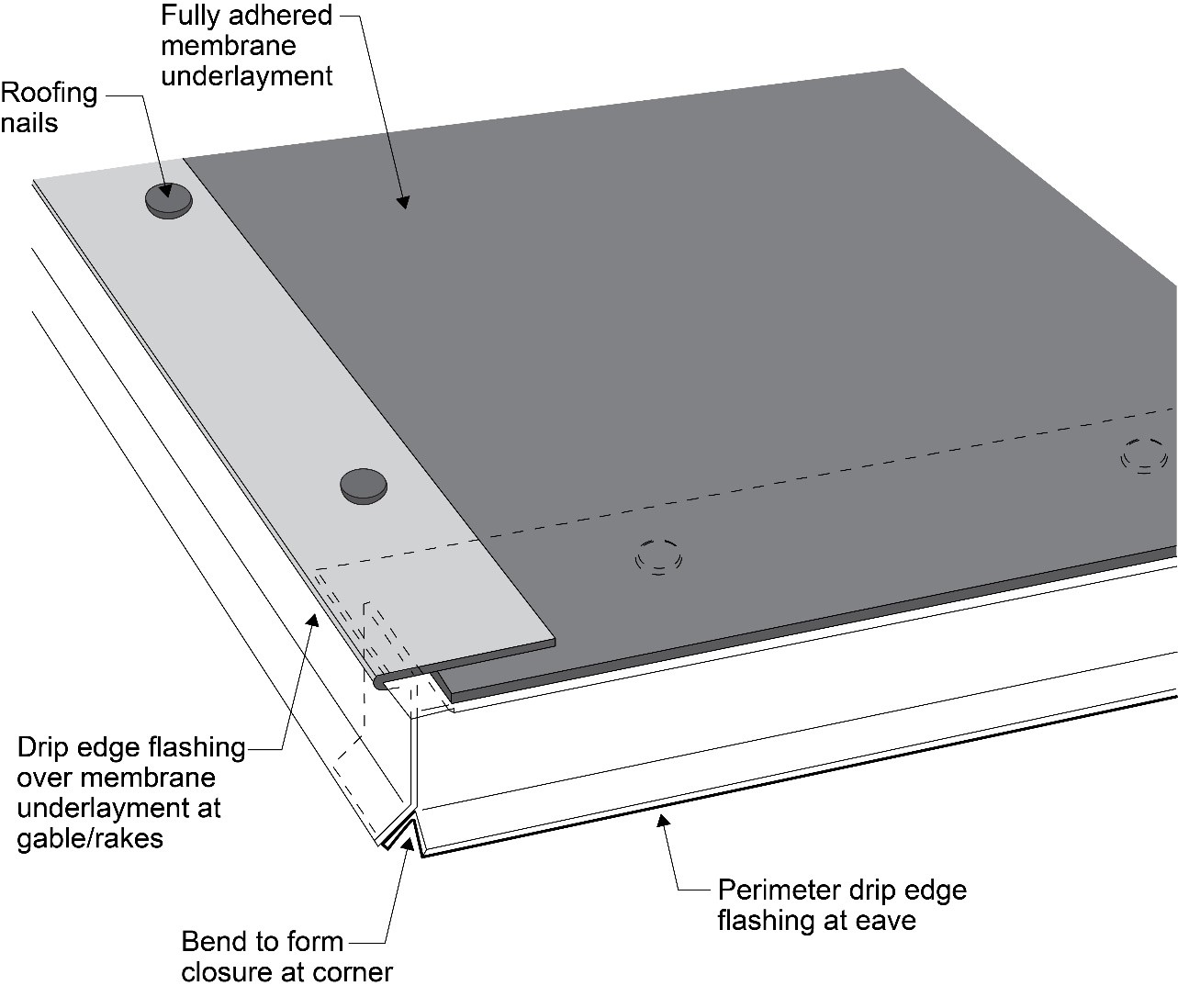
Right – If drip edge flashing is installed over fully adhered roof membrane at eaves, use flashing cement to seal the upper edge of the flashing
Image
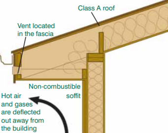
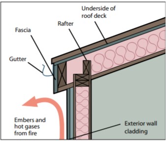
Right – In wildfire prone areas, using a flat soffit with venting on the fascia instead of an angled soffit with down-facing venting reduces the risk of catching rising embers.
Image
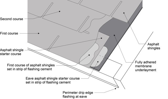
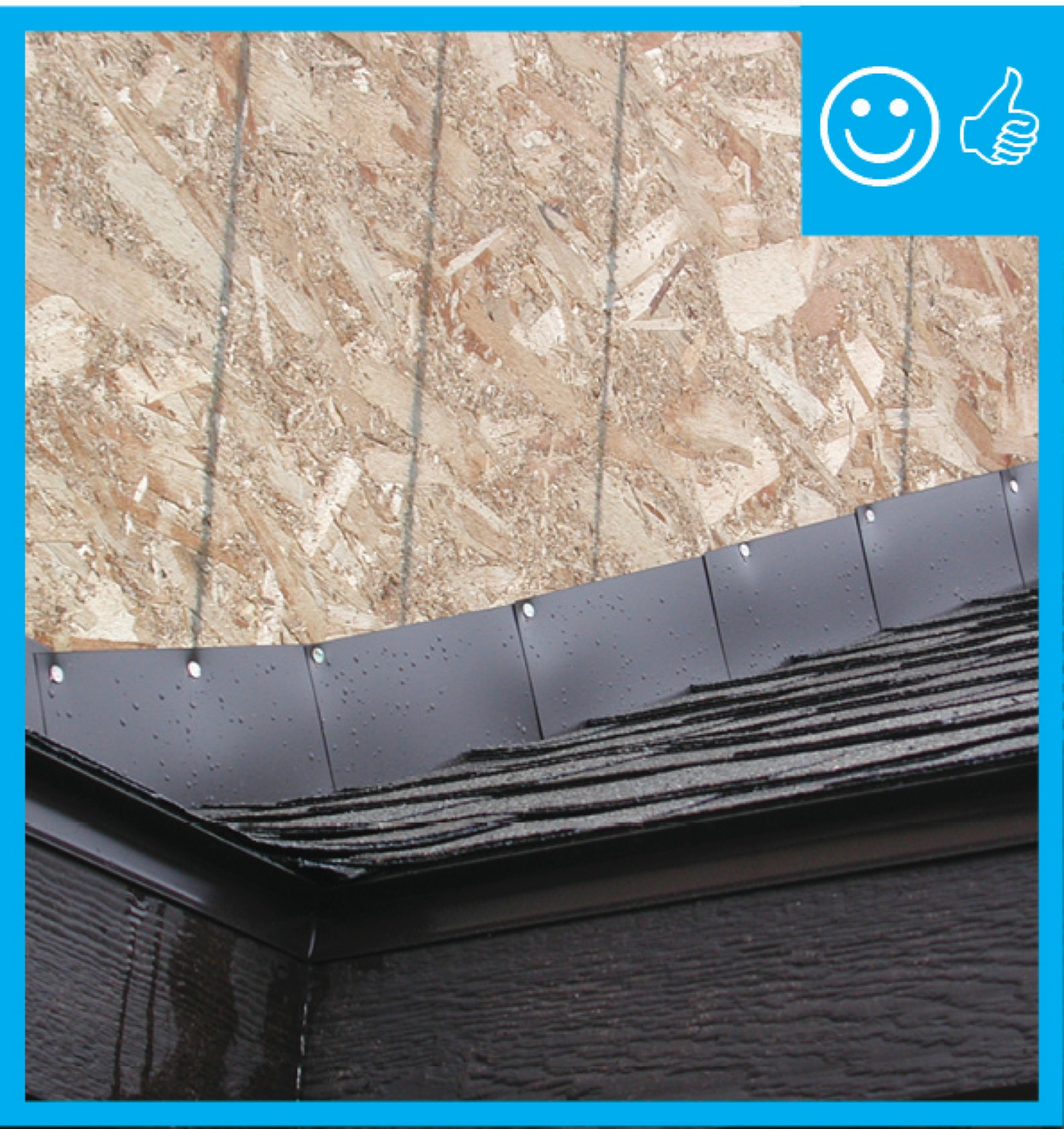
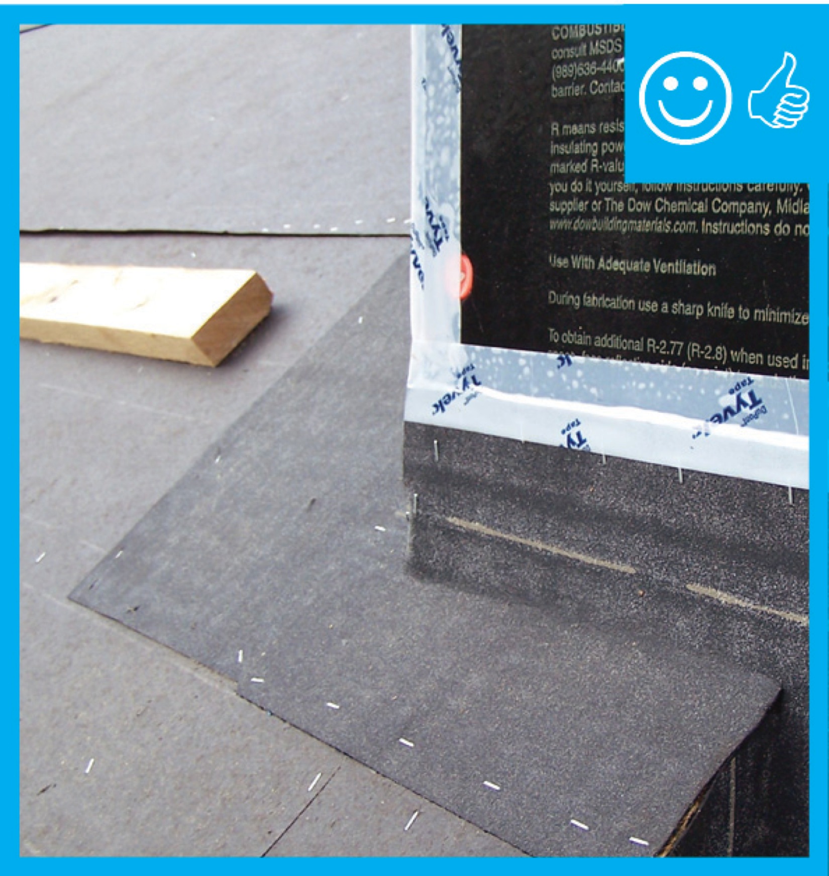
Right – Install asphalt shingles over a starter strip set in an 8-inch strip of flashing cement
Image
Image
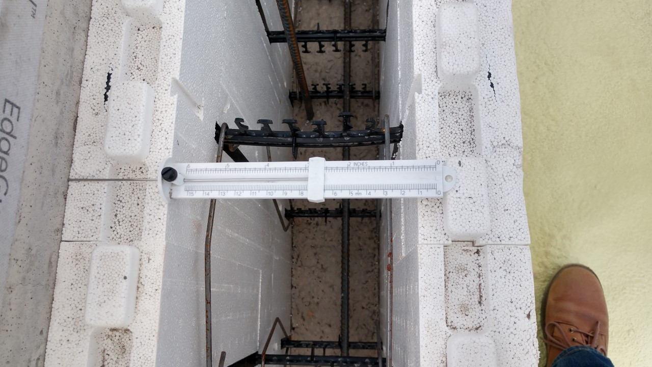
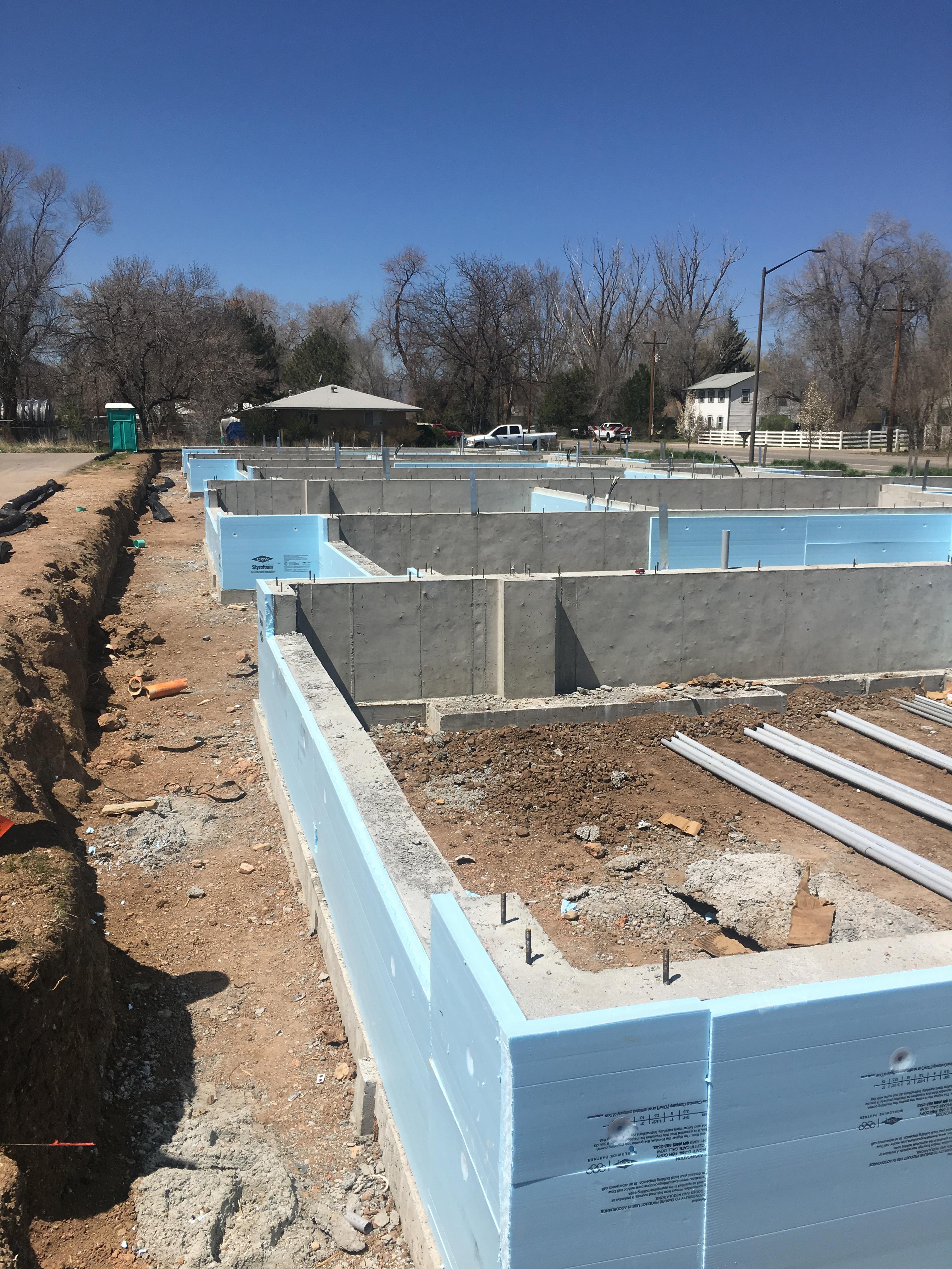
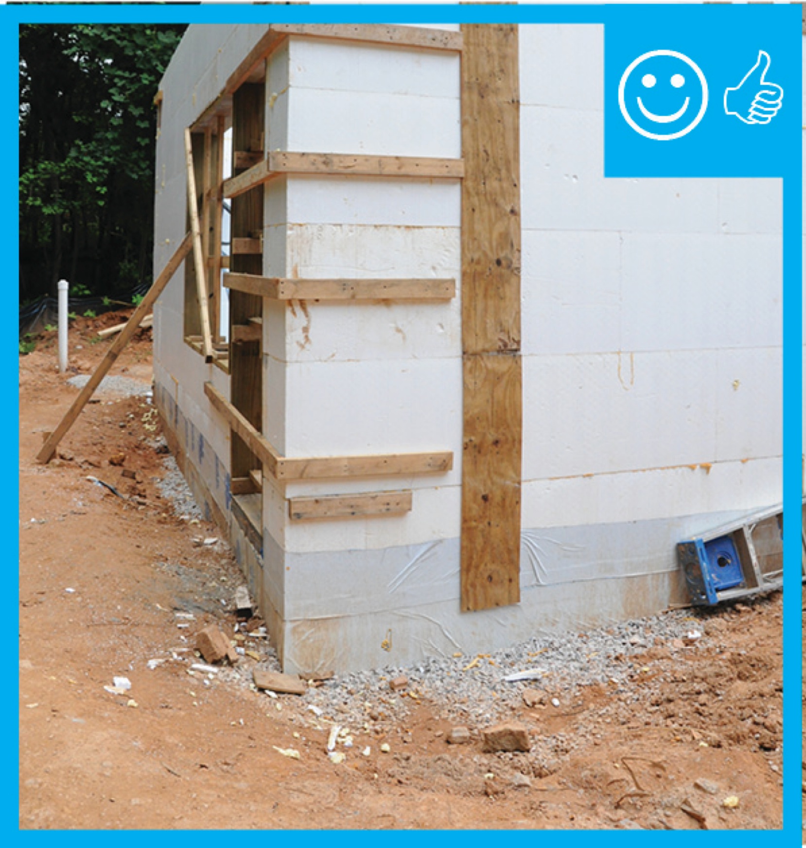
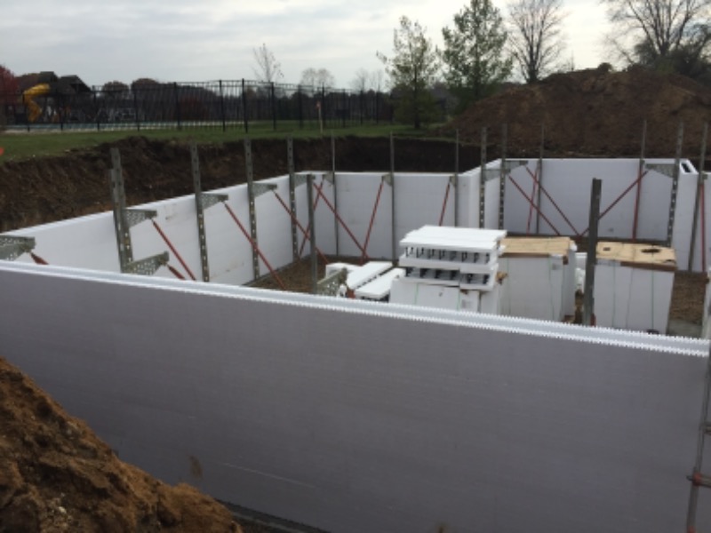
Right – Insulated concrete form (ICF) blocks are stacked like bricks, then rebar is set horizontally and vertically in the plastic spacers, then concrete is poured; the rigid foam and spacers stay in place to add support and thermal resistance to the wall
Image
Right – Insulated concrete forms (ICFs) provide the insulated stem wall for the slab-on-grade foundation for this SIP house.
Image
Image
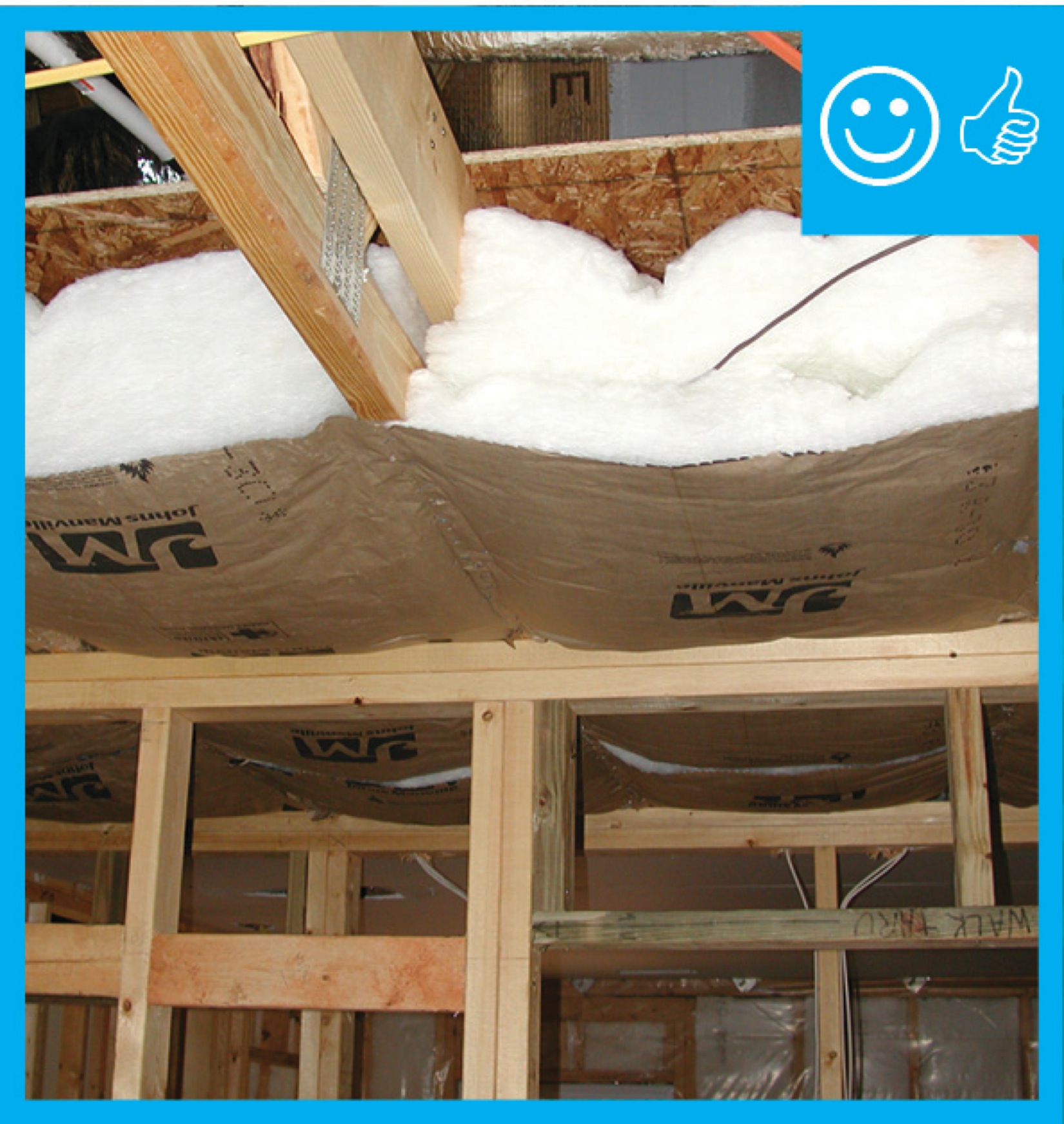
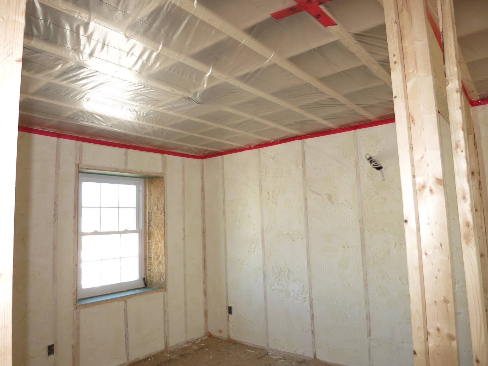
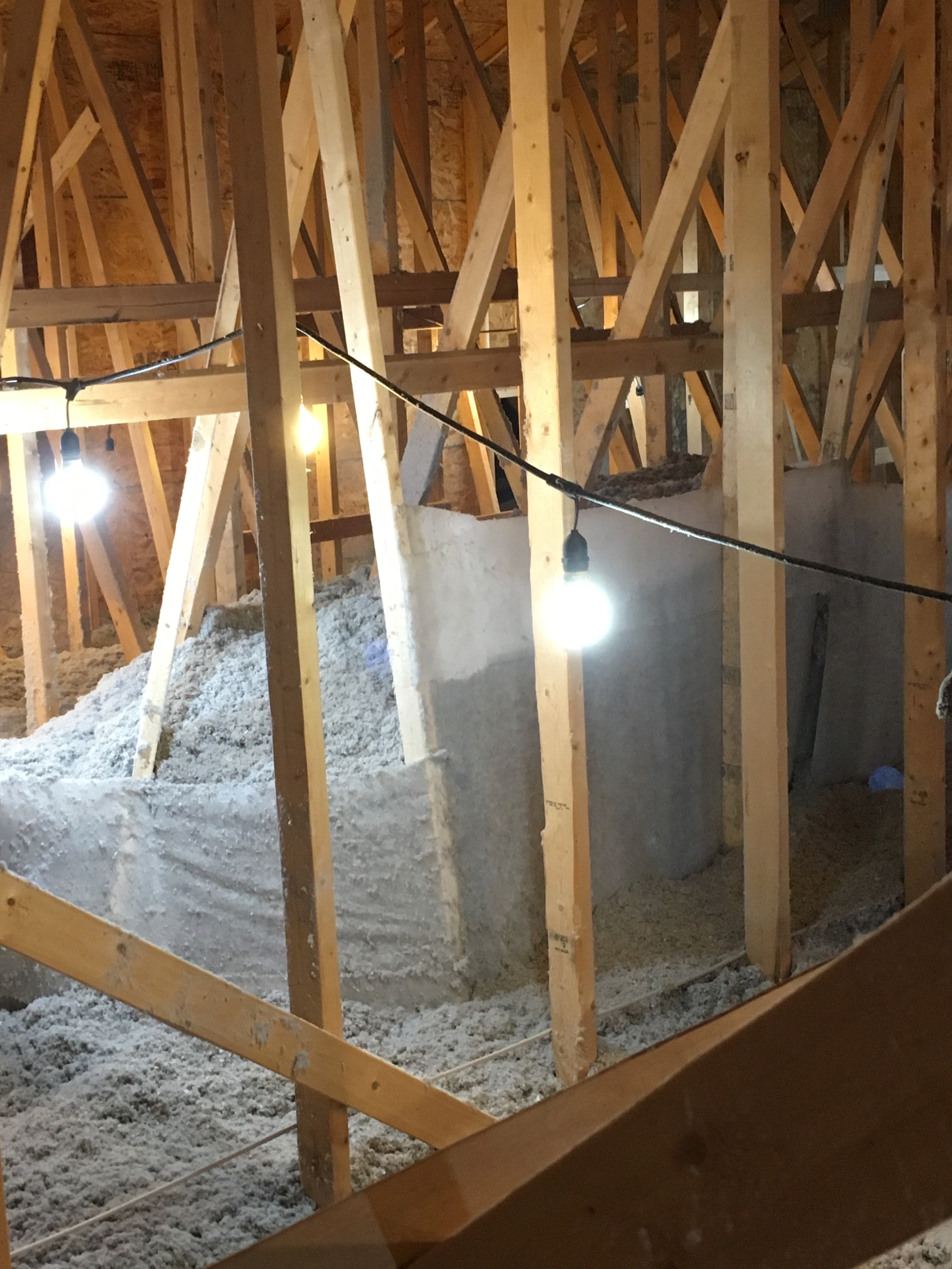
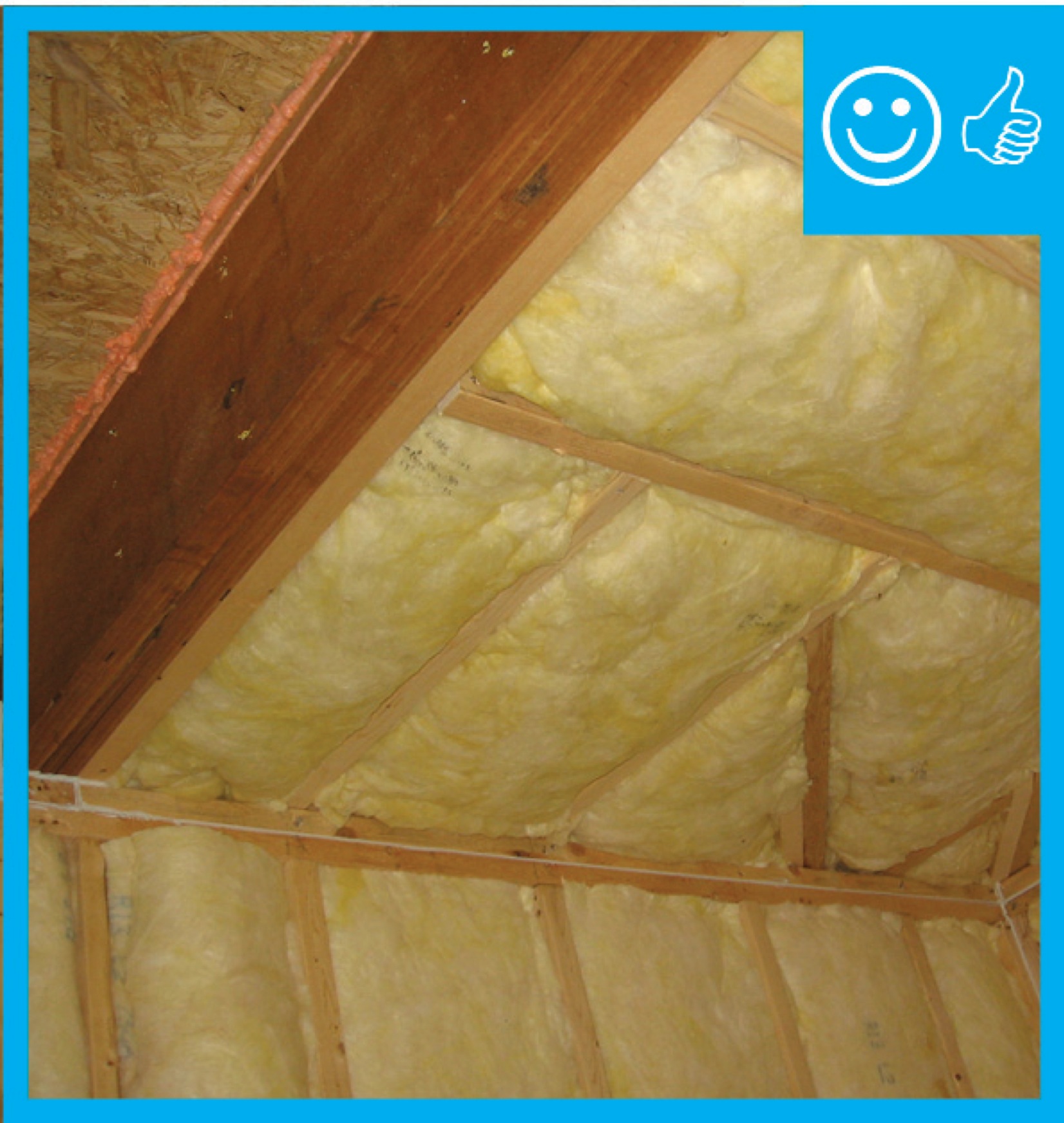
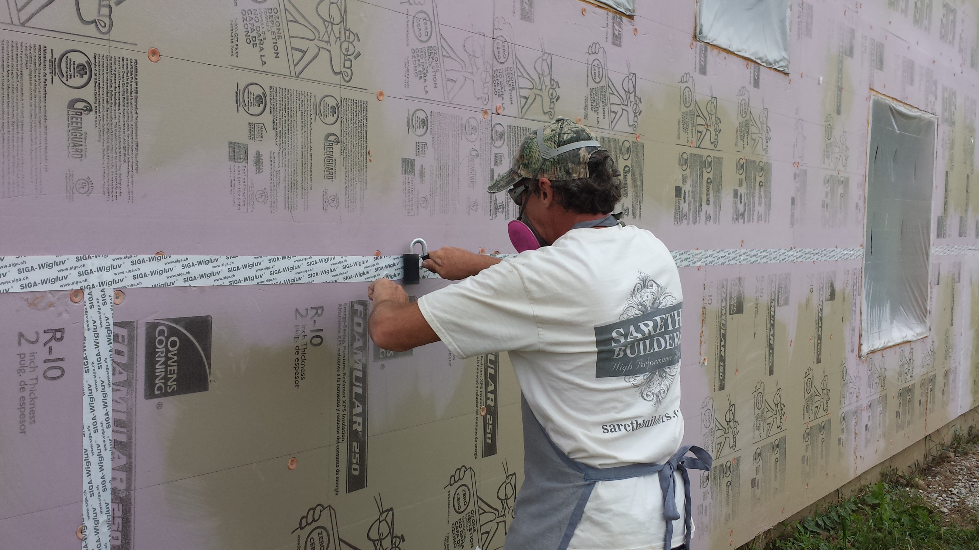
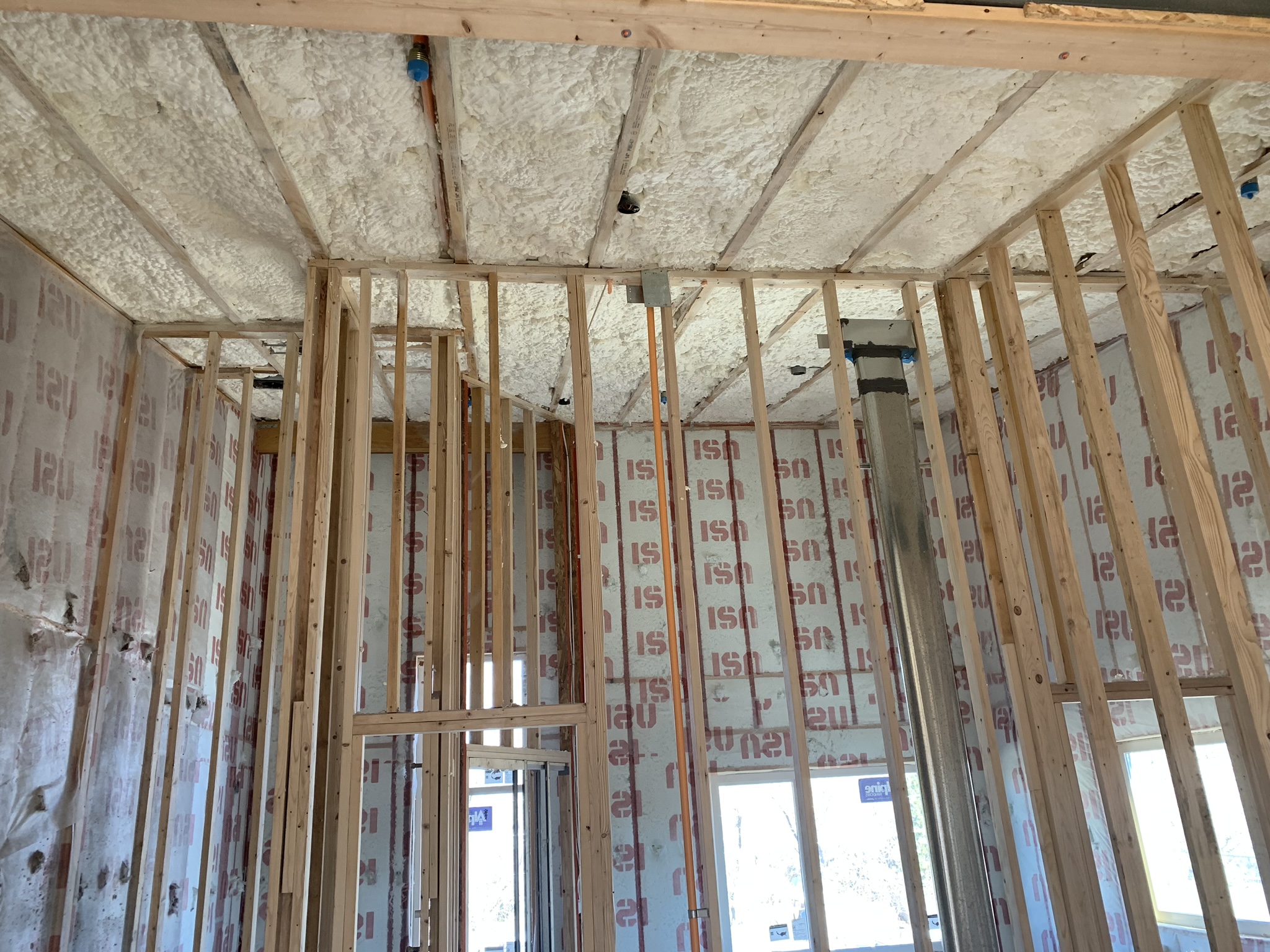
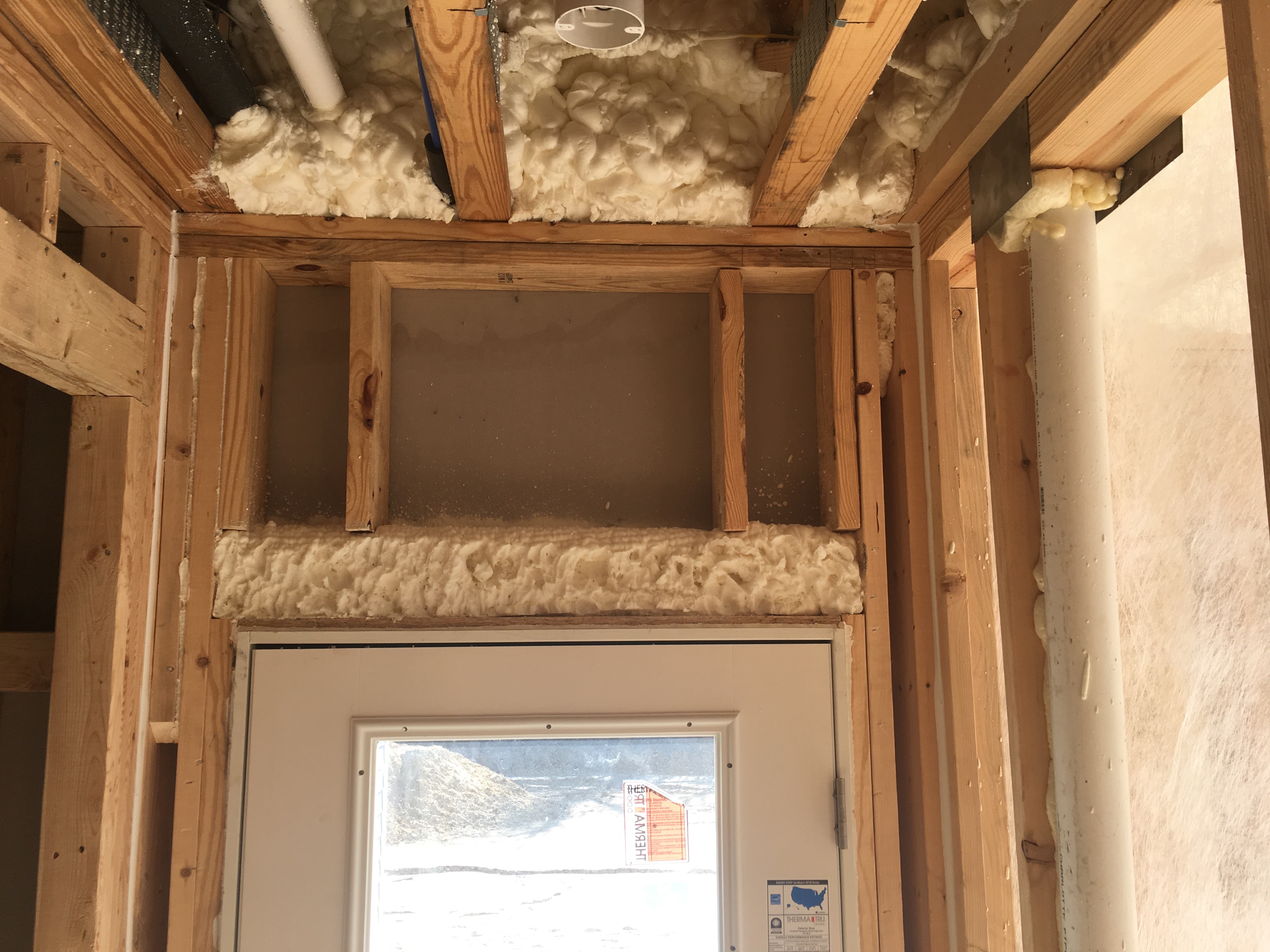
Right – Insulation installed to correct depth and will be aligned with air barrier
Image
Image

Image
Image
Image
Image
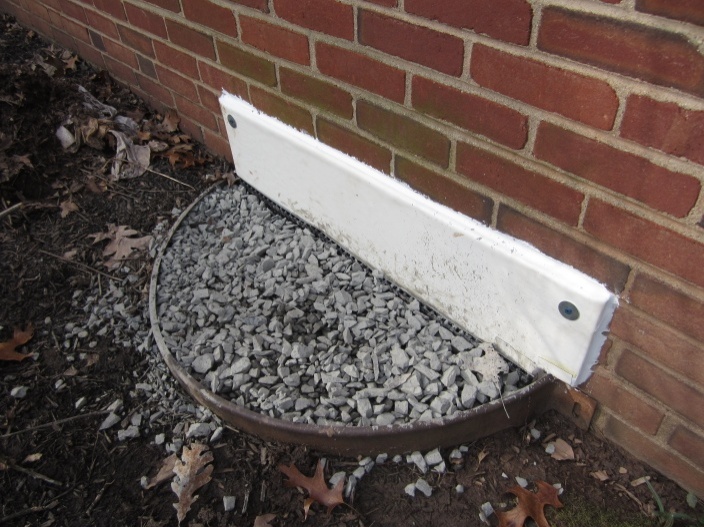
Right – Interior grade is elevated and flood vents are located slightly above interior grade
Image
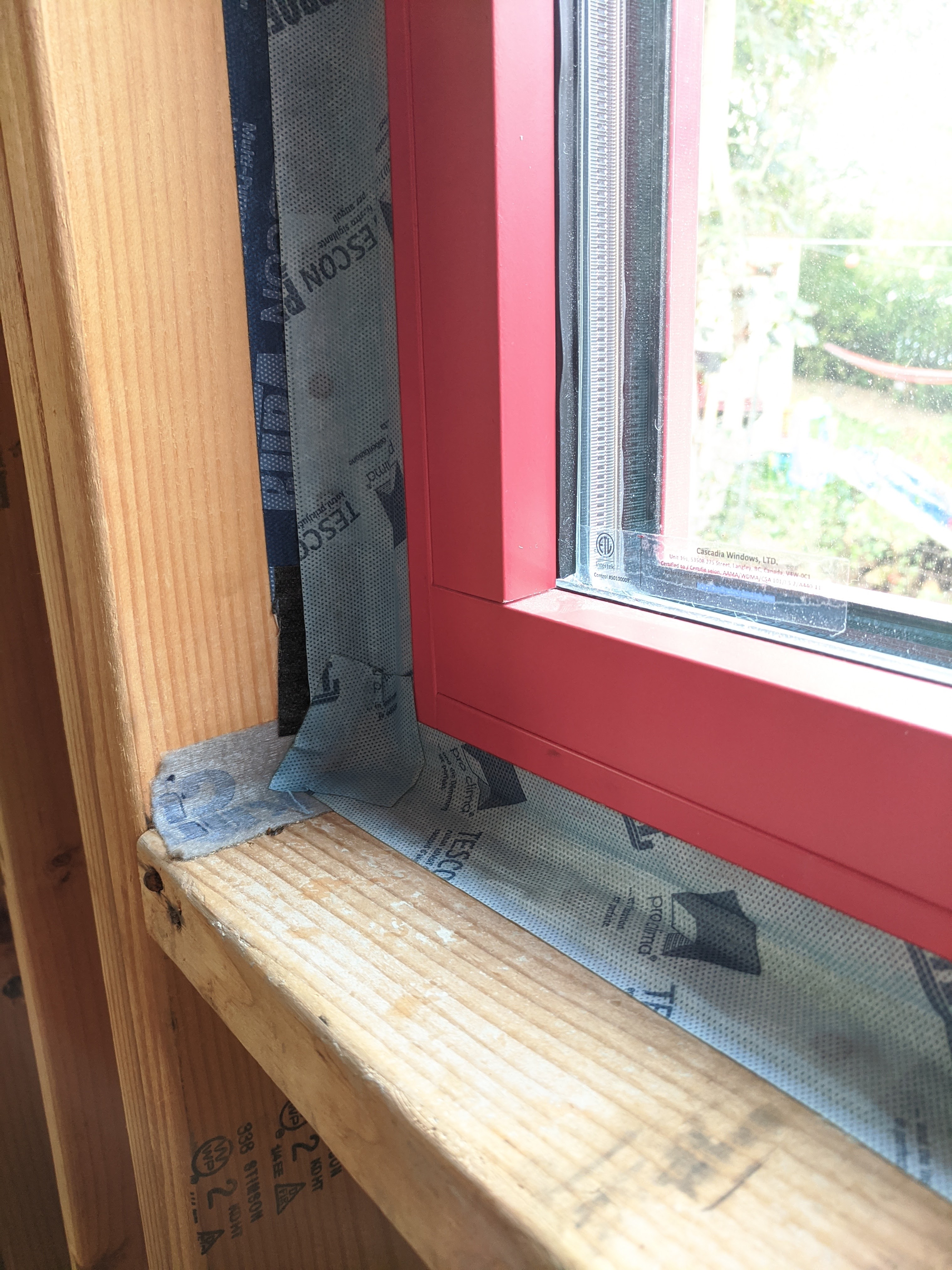
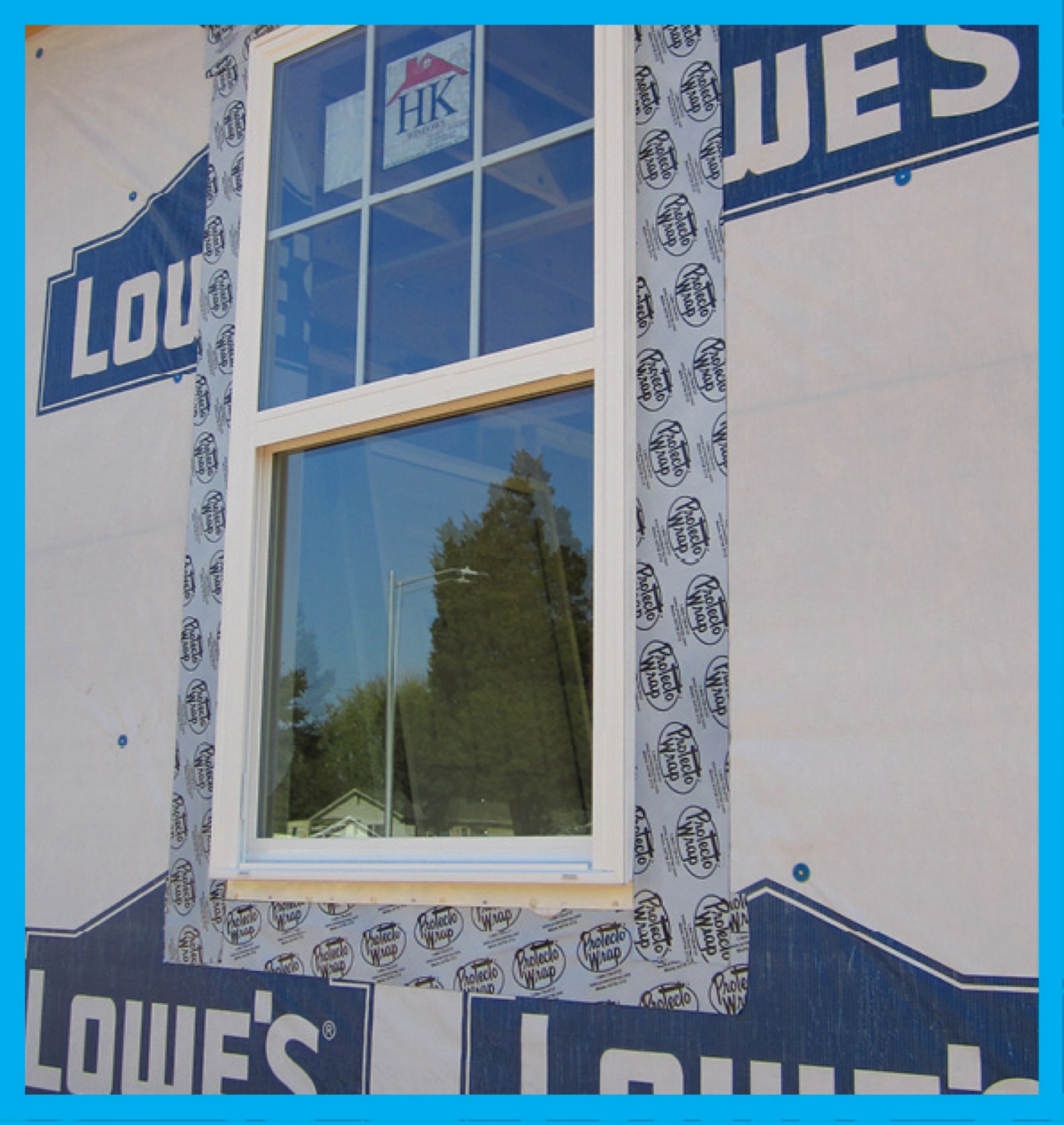
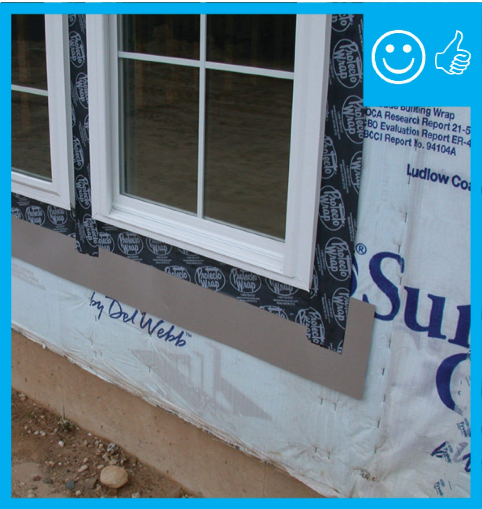
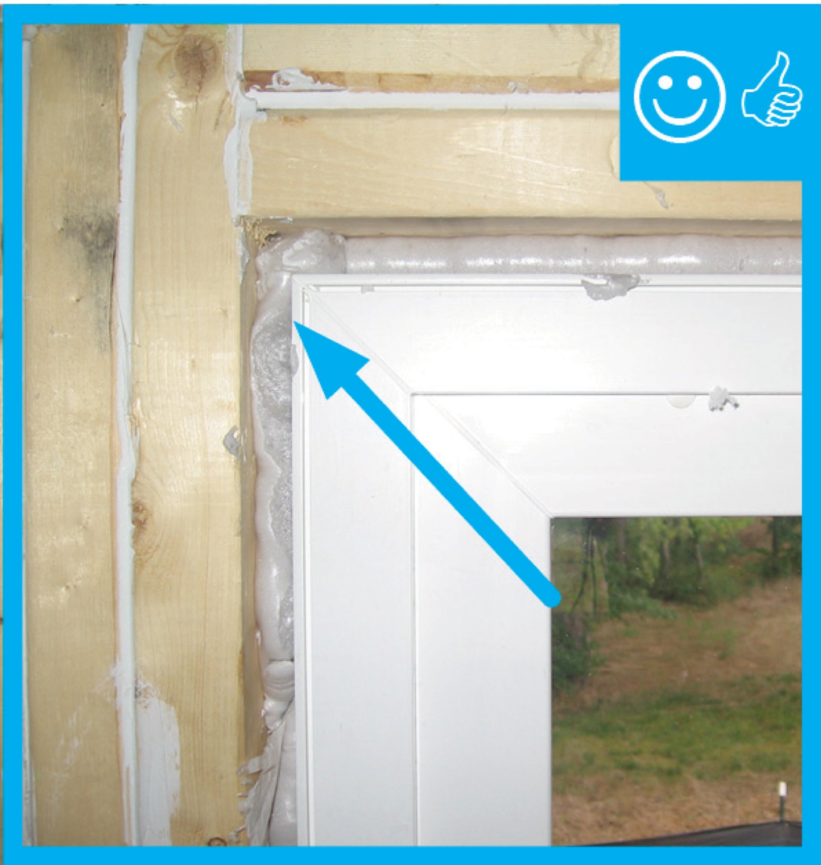
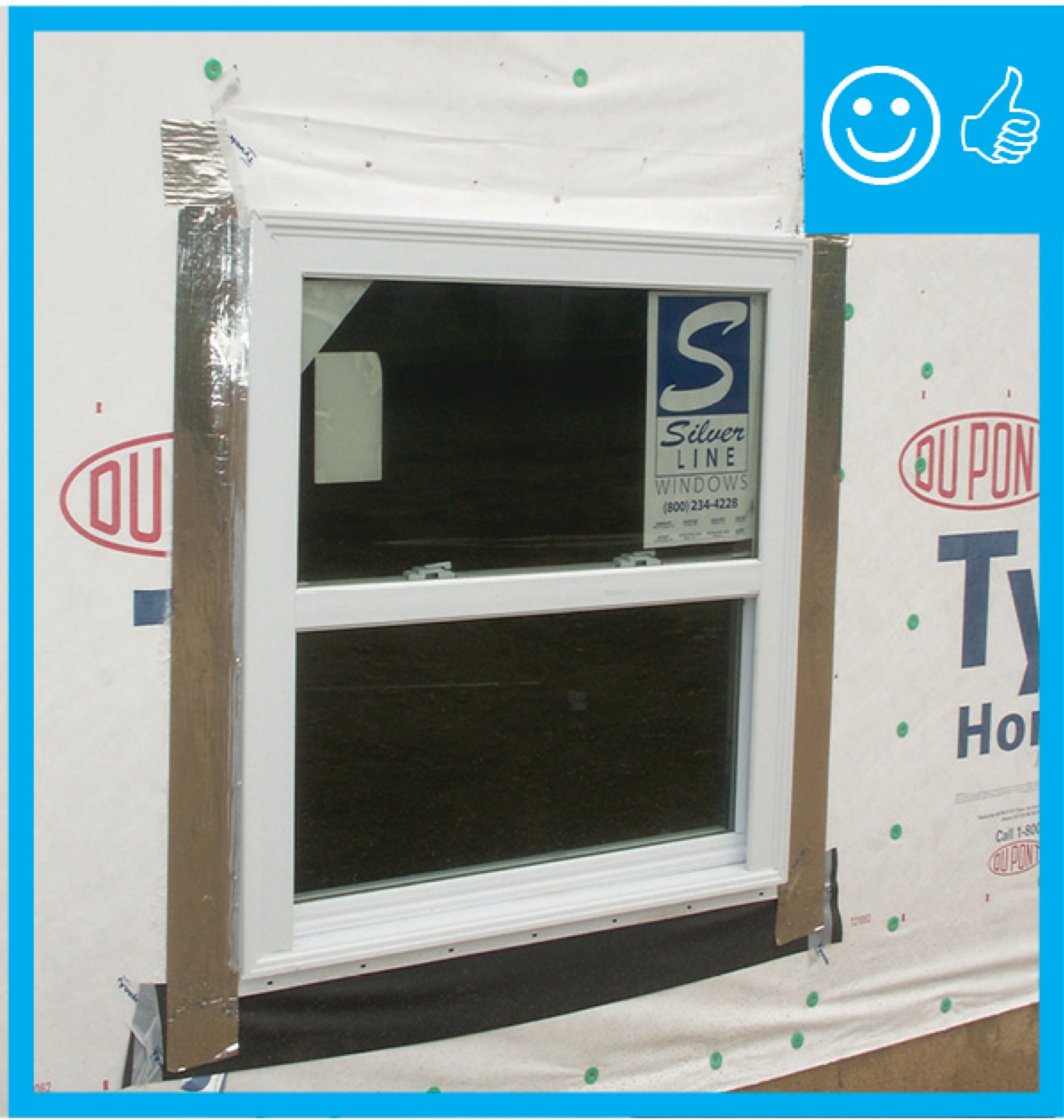
Right – Interior wood-to-wood seams around a window are sealed with tape to prevent air leakage.
Image
Right – Joists between floors are air sealed to the ceiling drywall with canned spray foam along each joist-to-drywall-seam.
Image
Image
Image
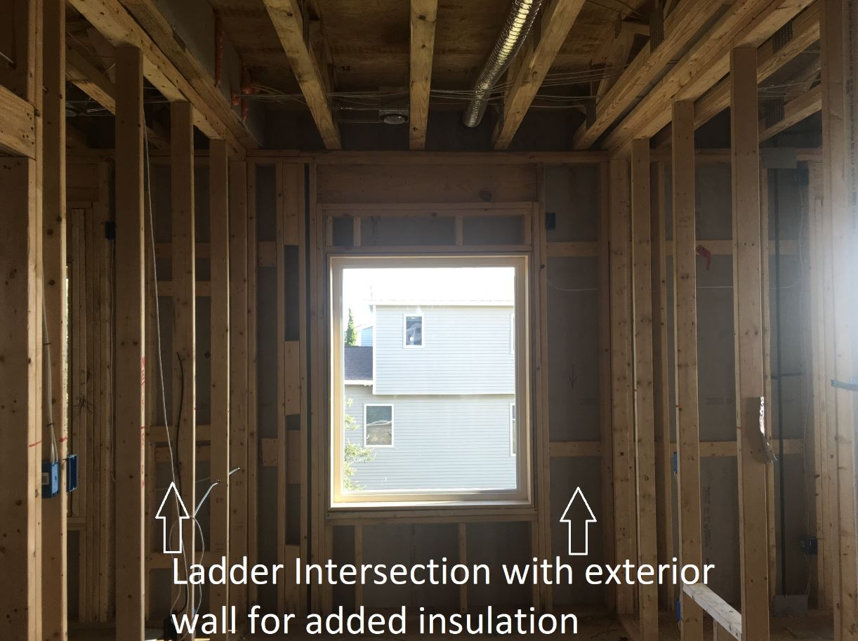
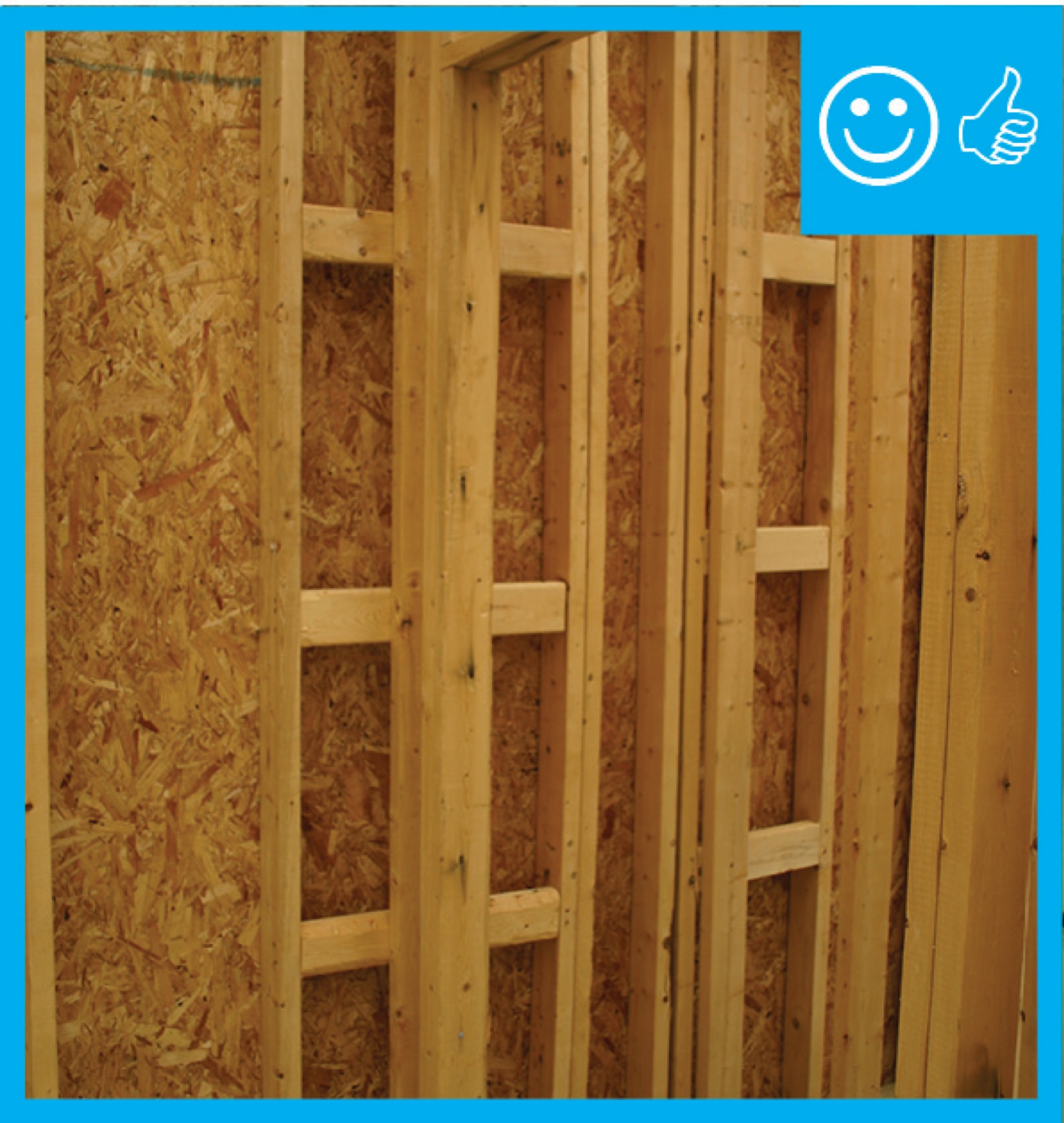
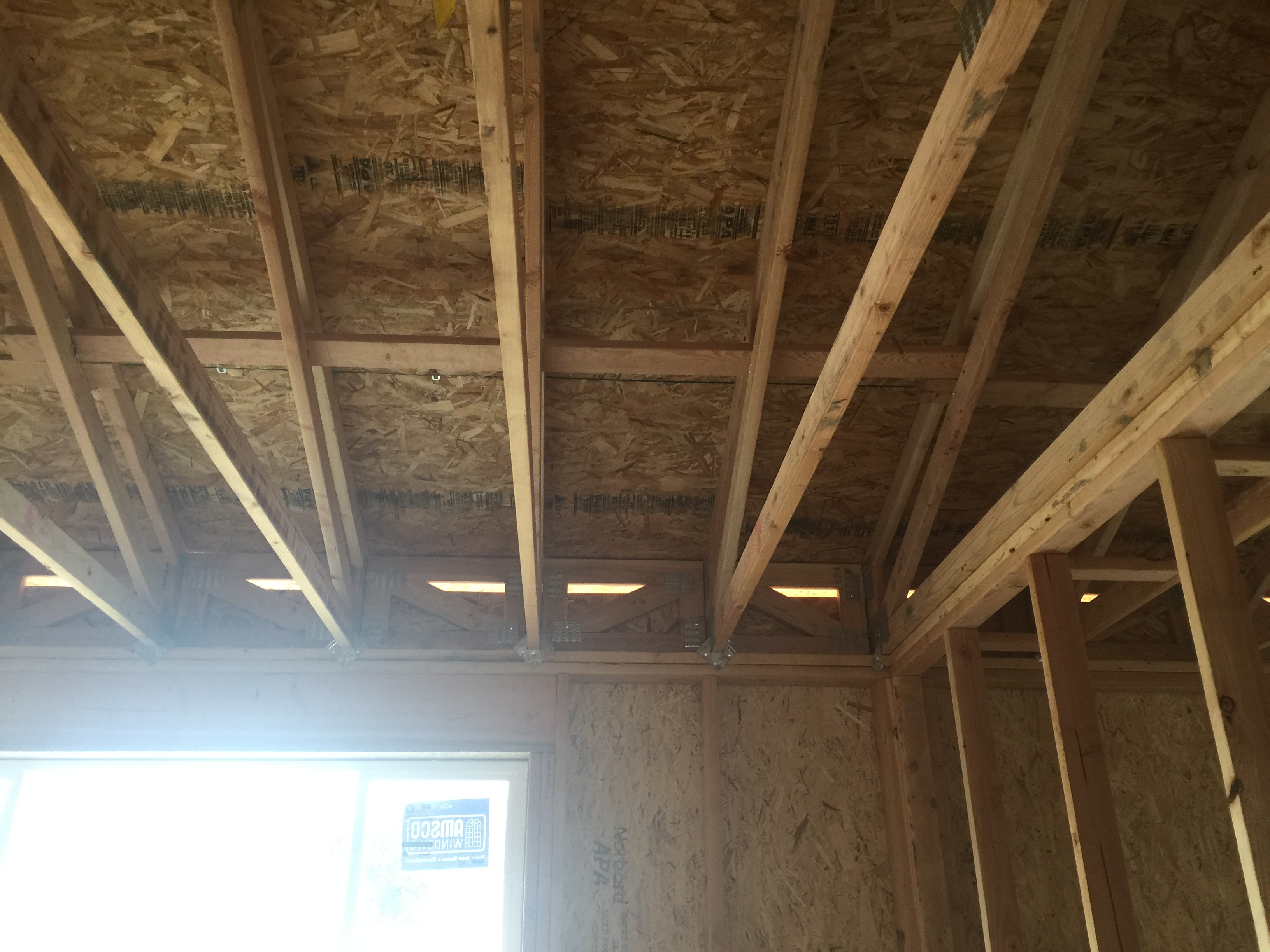
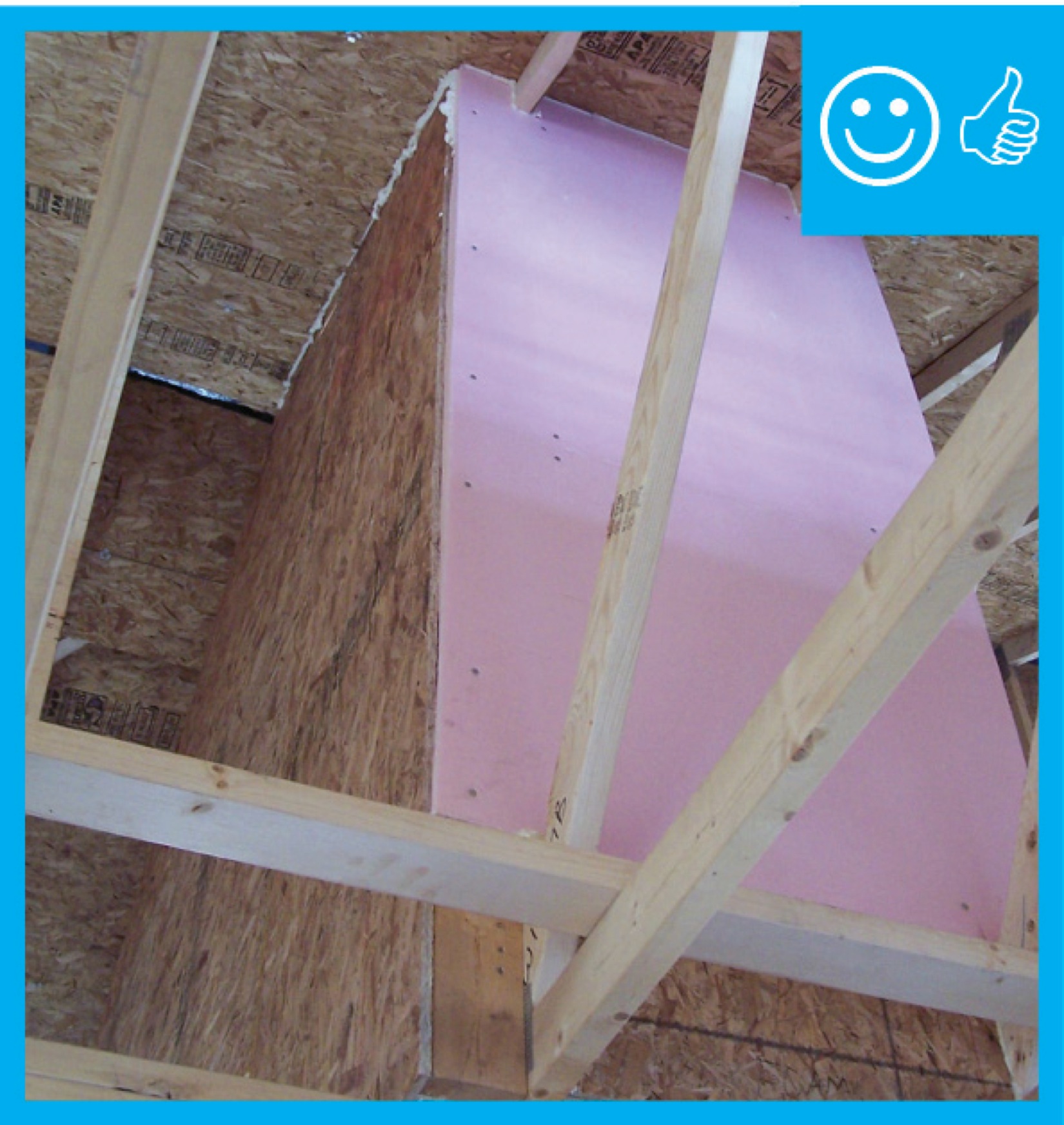
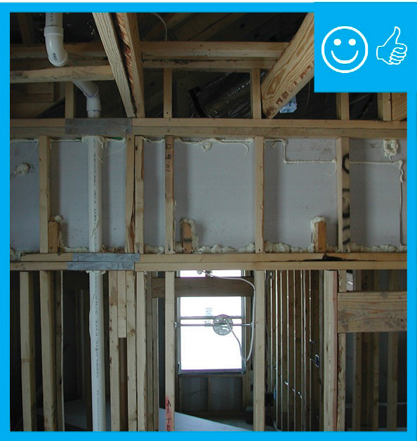
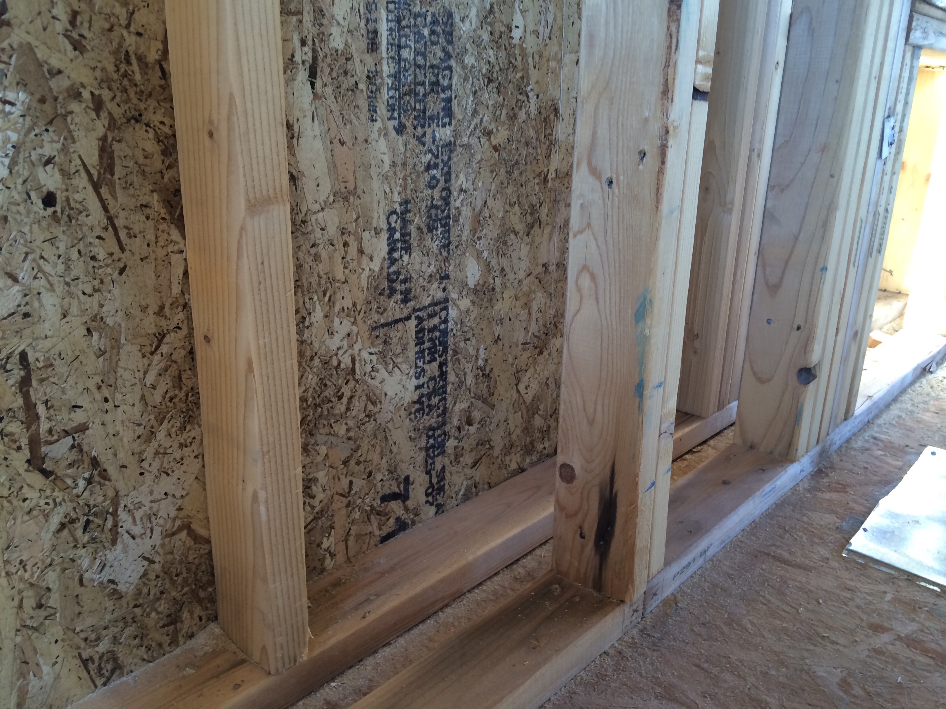
Right – Ladder blocking allows the exterior wall to be insulated where intersected by an interior wall.
Image

Image
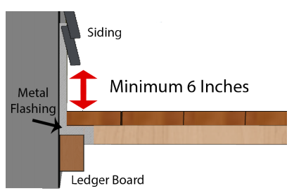
Right – Metal flashing is installed between the deck boards and house wall with the top of the flashing extending up behind the siding and the bottom of the flashing extending out and down over the ledger board
Image
Image
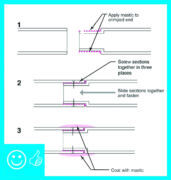
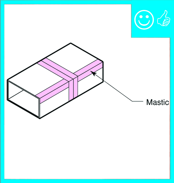
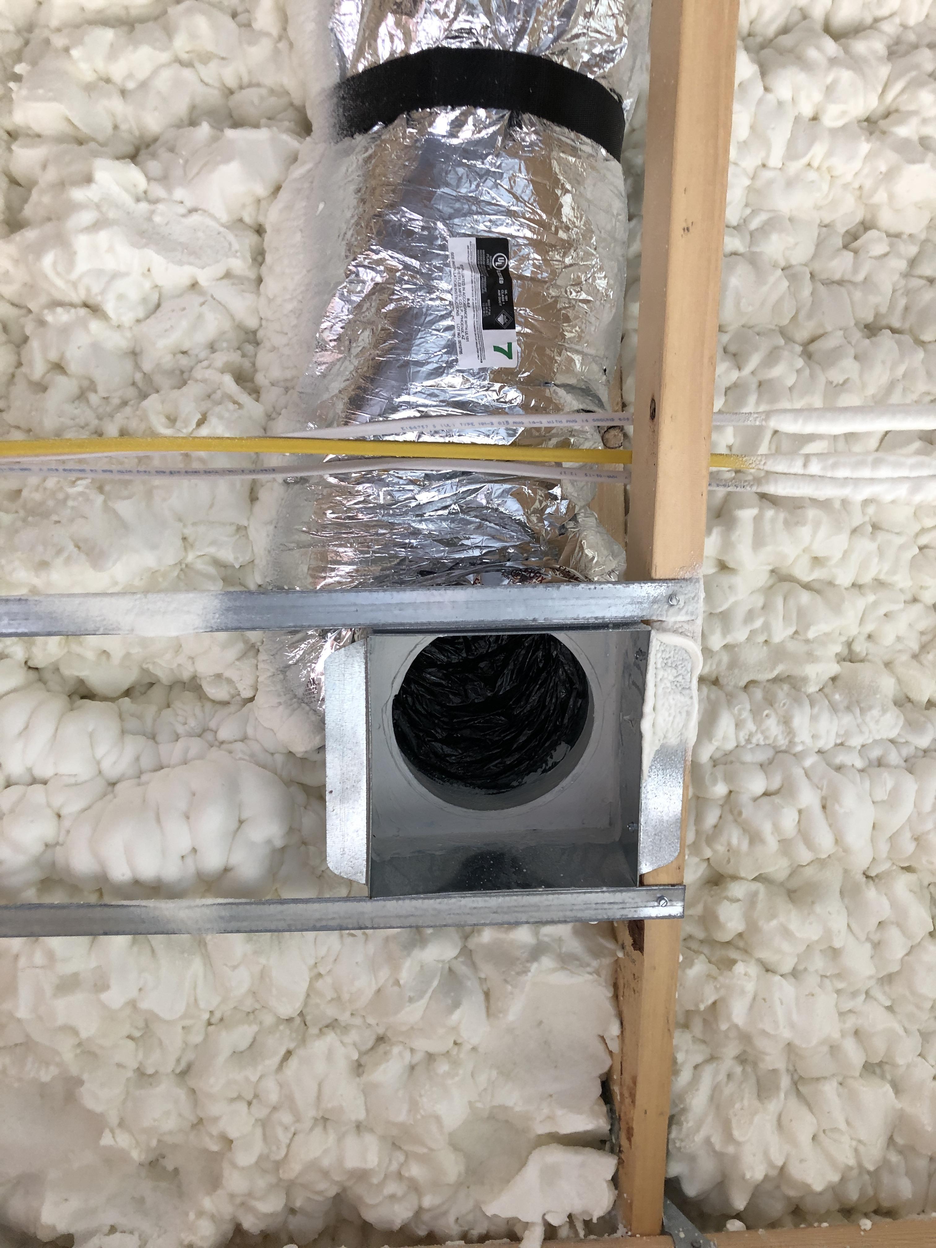
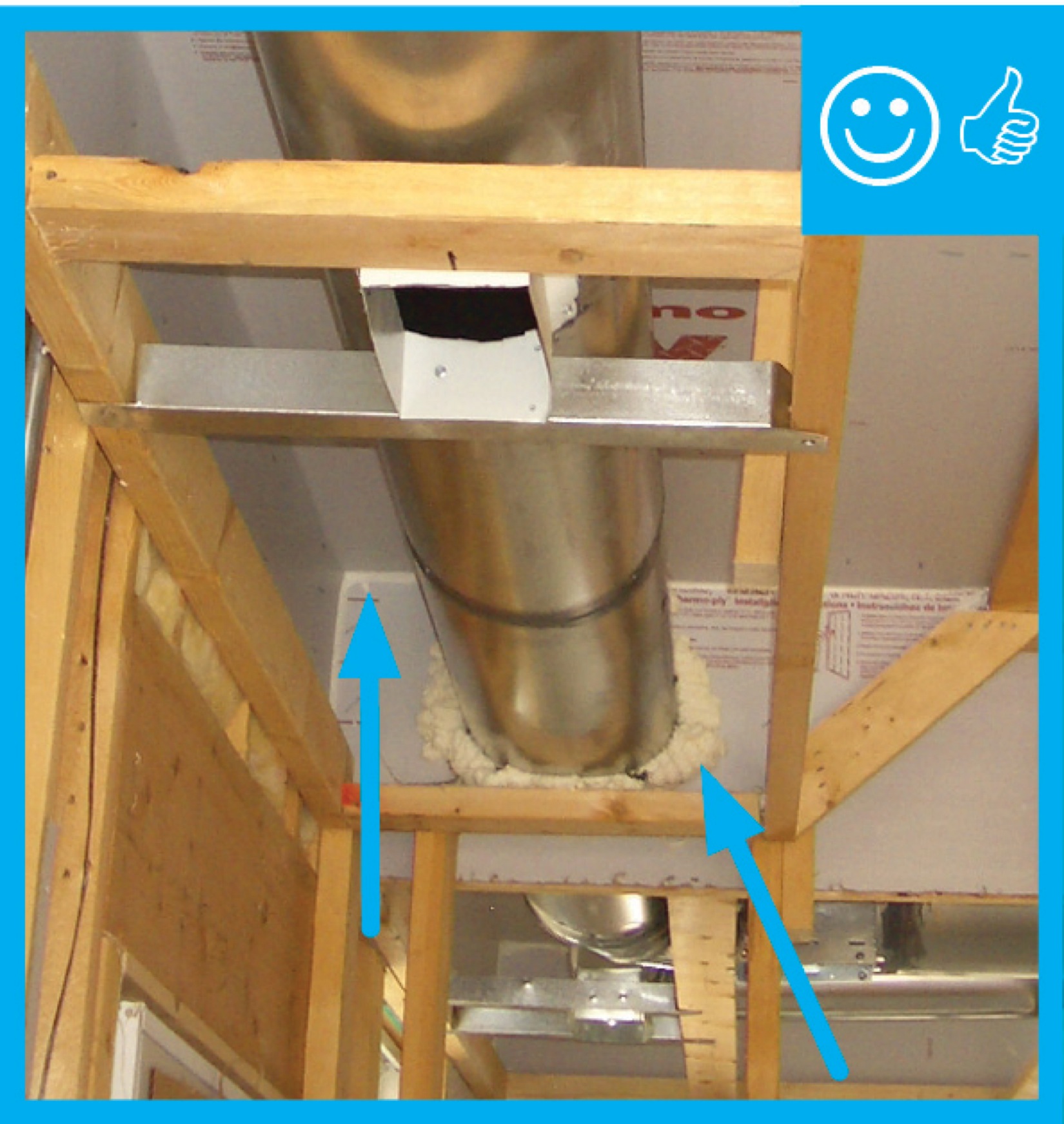
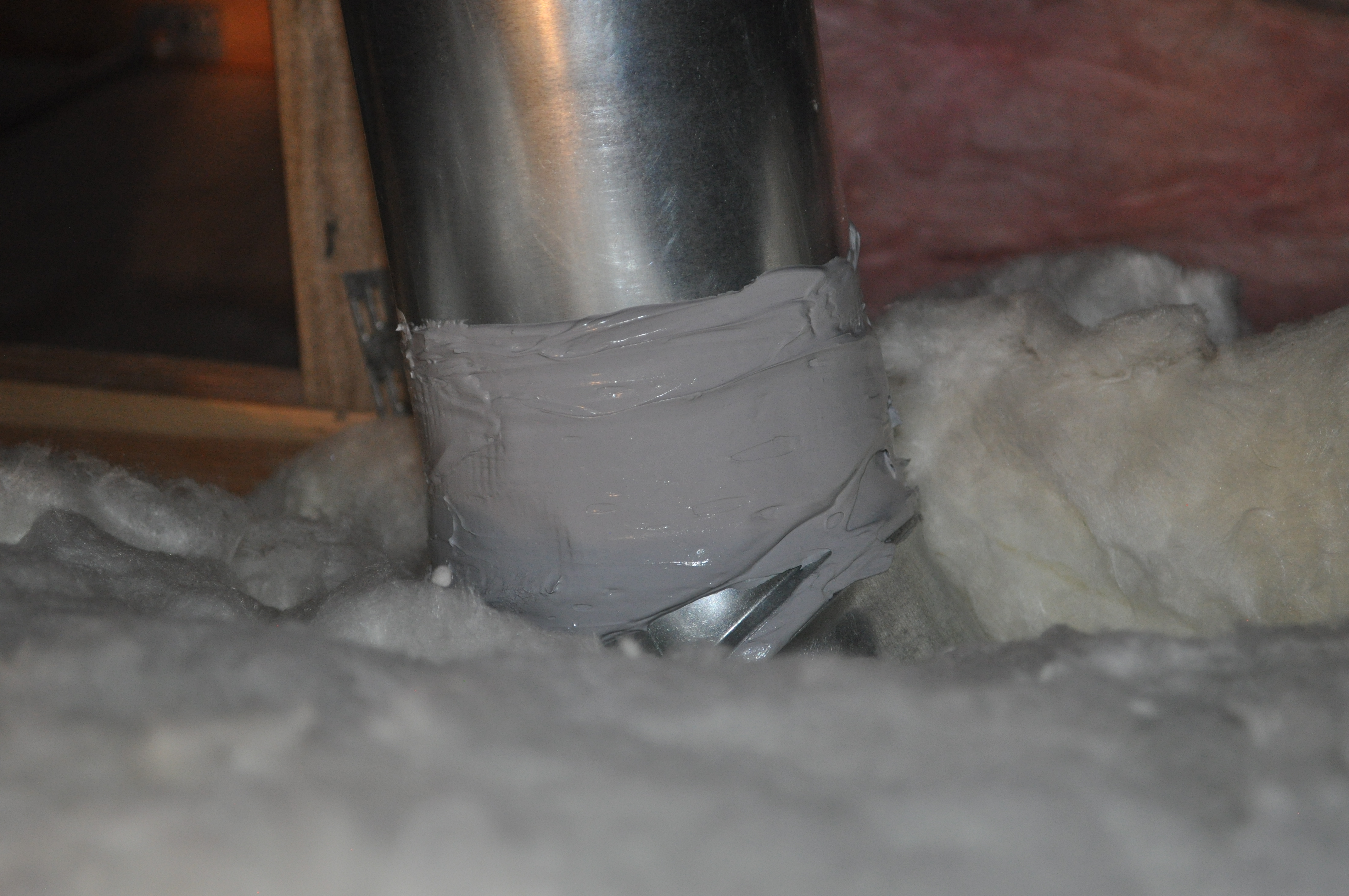
Right – Metal or fiberboard duct is mastic sealed at junction with duct register box
Image
Image
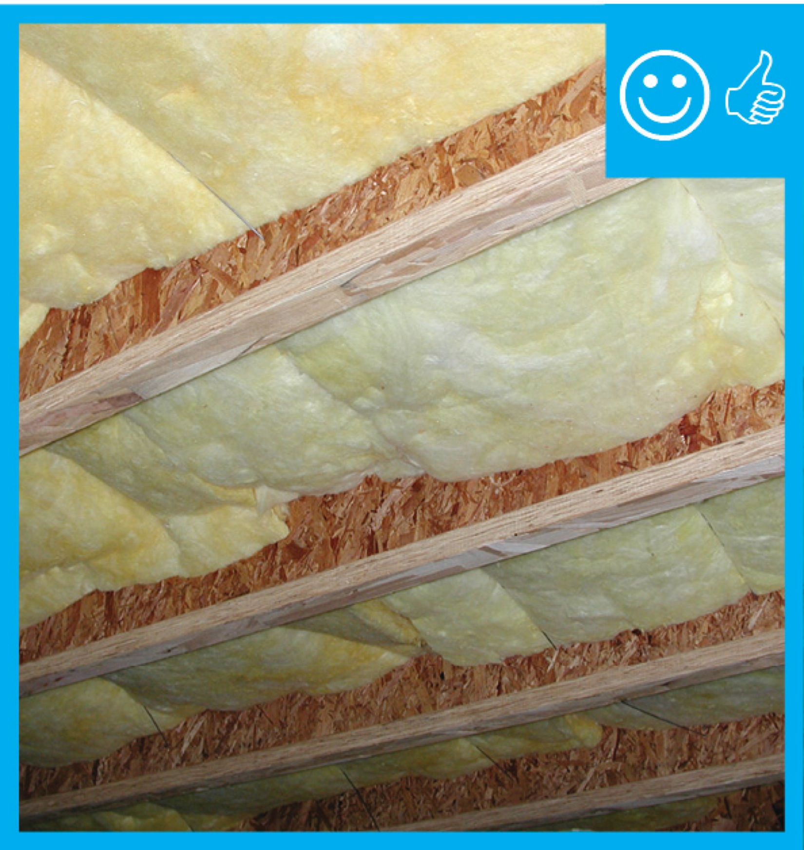
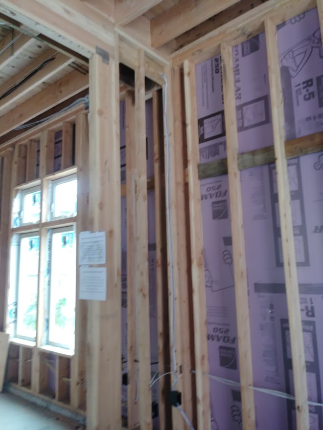
Right – Mineral wool batt insulation is cut to fit snuggly and to fully fill wall cavities with minimal voids and gaps.
Image
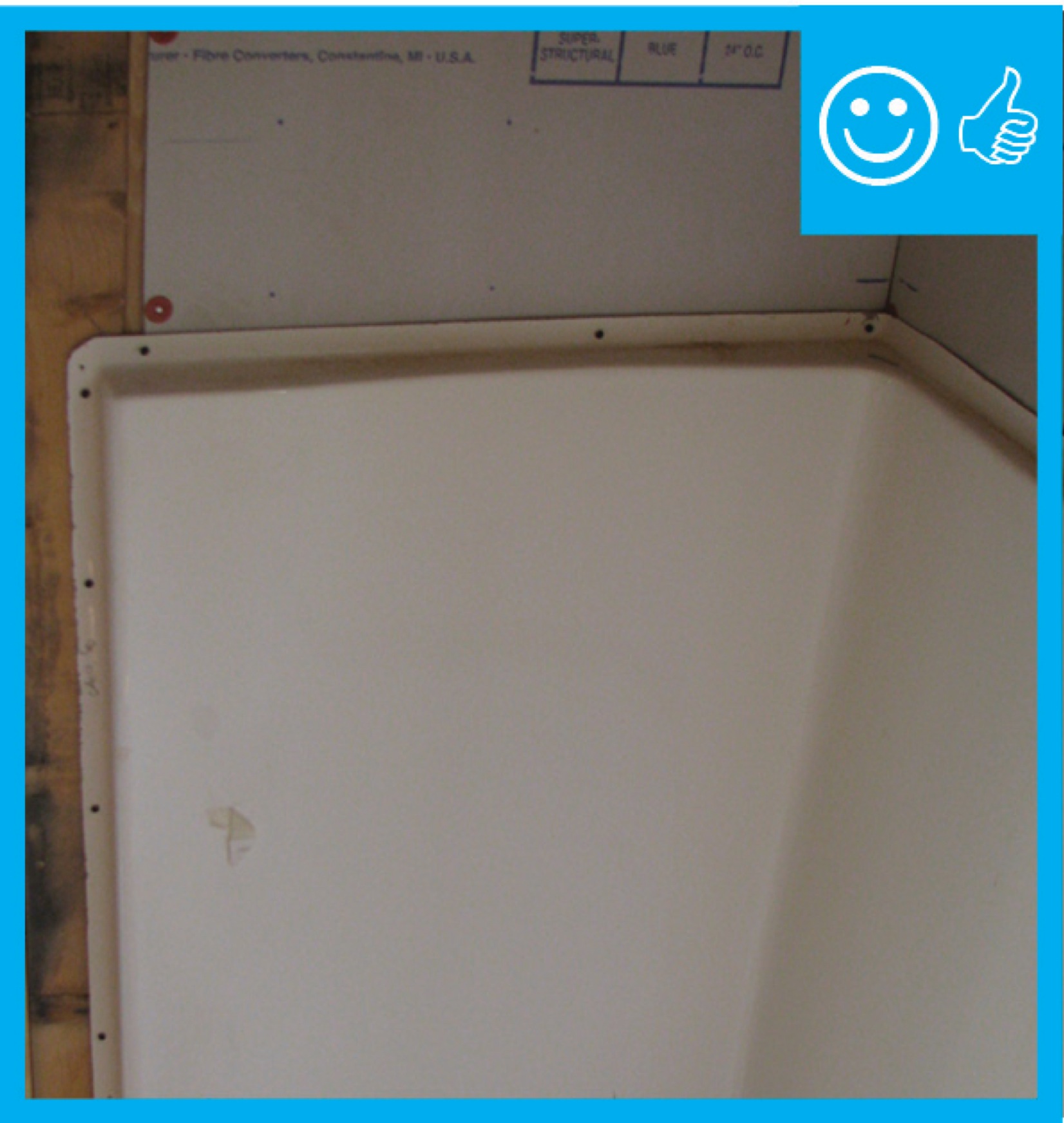
Right – Moisture-resistant backing material has been used above and behind the tub enclosure.
Image
Right – Mold- and termite-resistant borate-treated lumber are used to make the panels of this kit home which are connected with metal strapping for hurricane and wind resistance.
Image
Image
Image
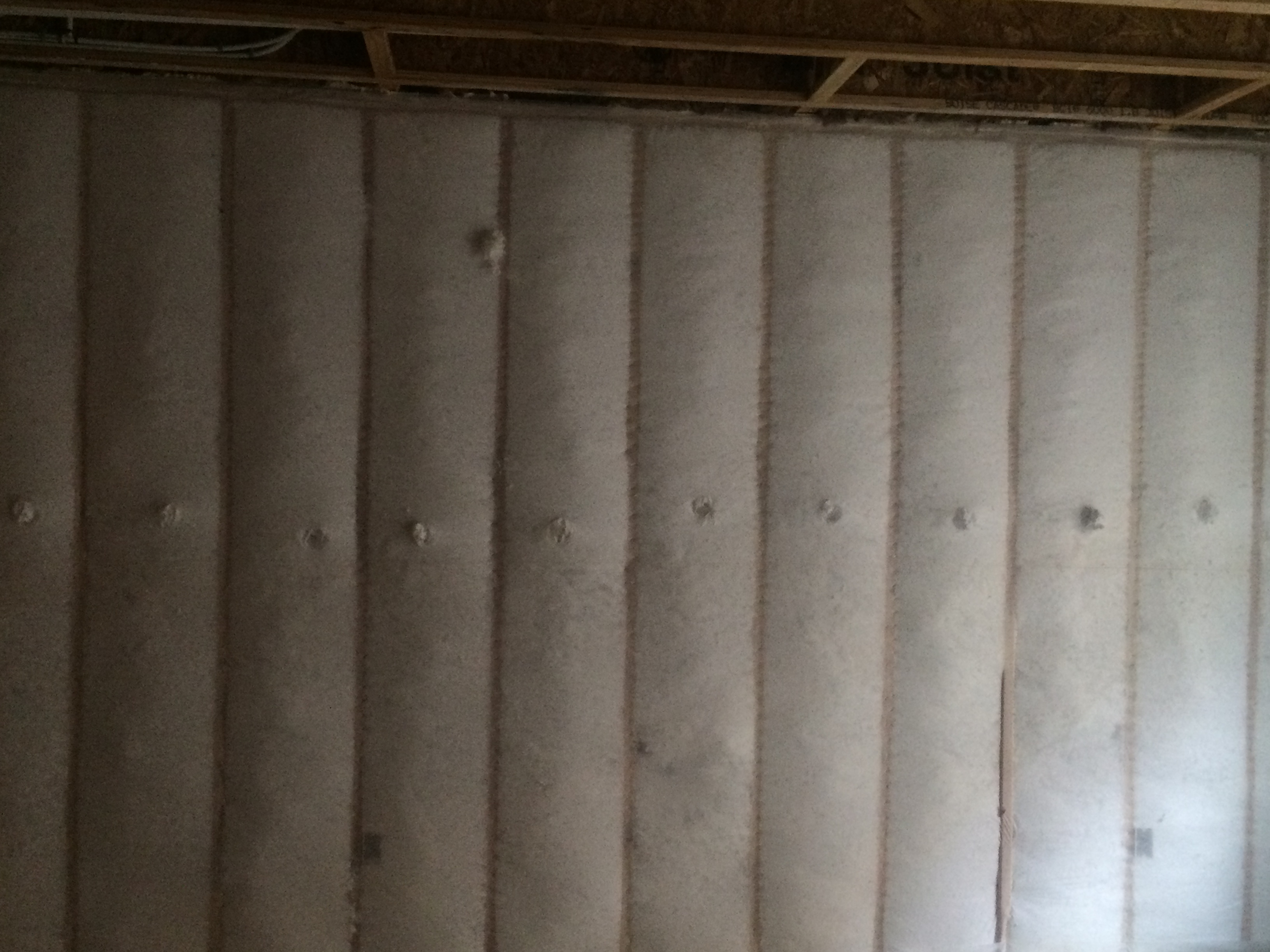
Right – Netted blown fiberglass insulation completely fills the wall cavities with no gaps or voids.
Image
Image
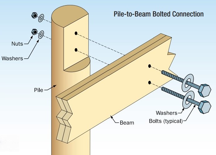
Right – Notch cut into pile takes less than 50% of cross section, cut is treated with wood preservative, and beam is installed with corrosion-resistant bolts.
Image
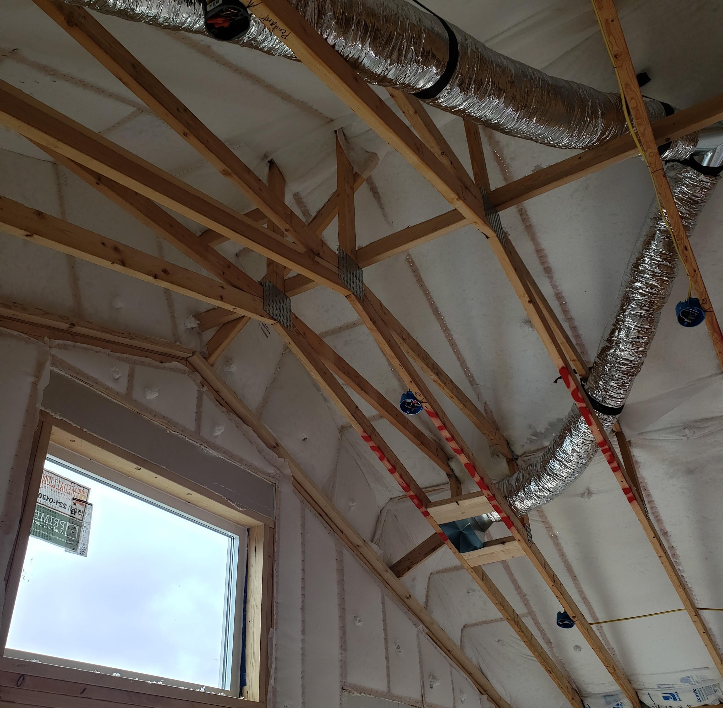
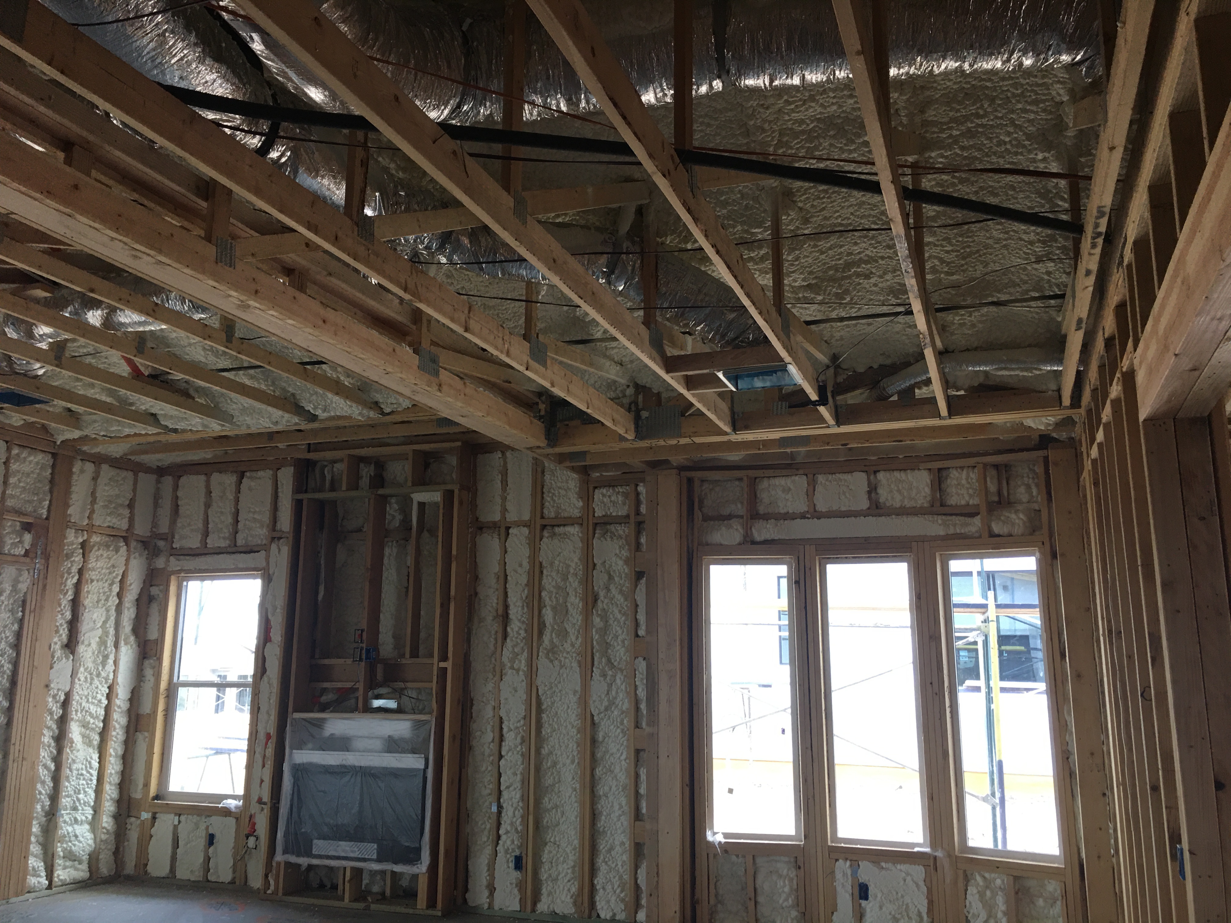
Right – Open web floor joists can provide a space between floors for HVAC ducting.
Image
Image
Image
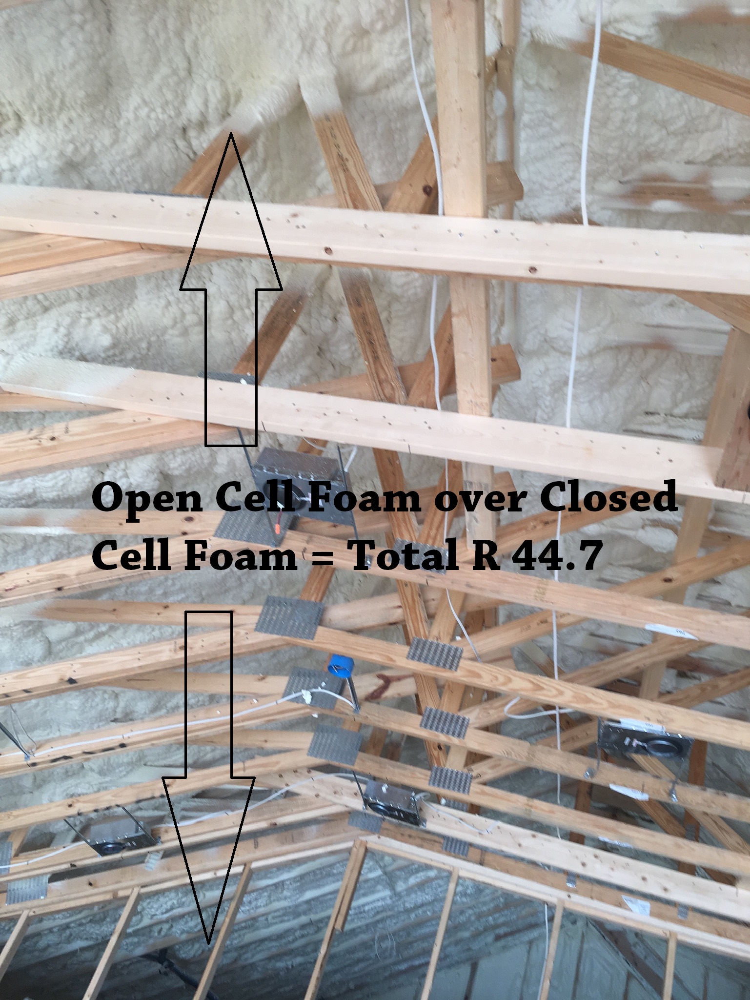
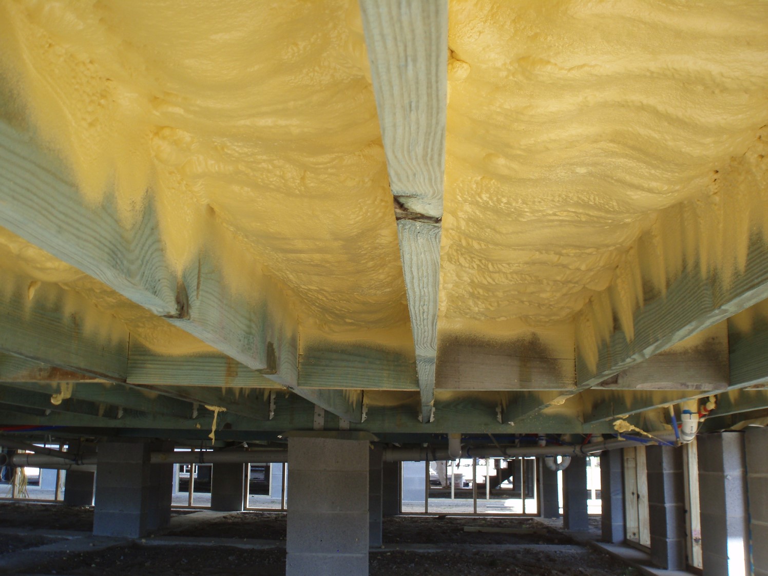
Right – Open-cell spray foam is installed over closed-cell spray foam in this hybrid approach to achieve adequate attic ventilation while allowing some vapor permeability.
Image
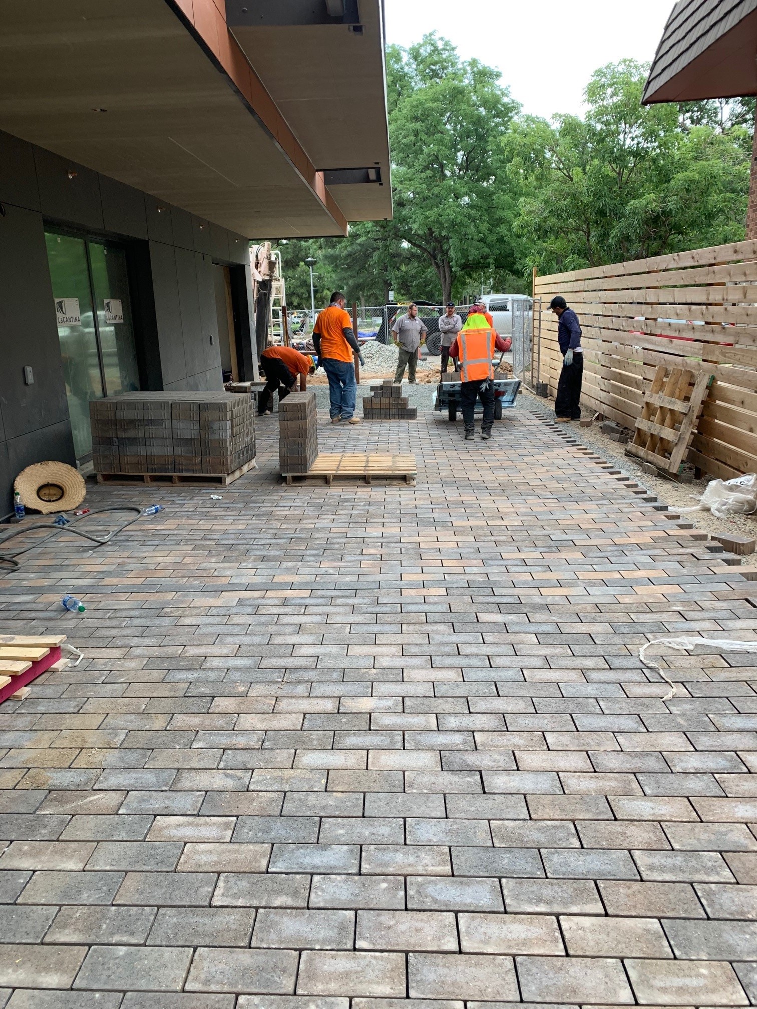
Right – Pavers provide a pervious ground surface allowing storm runoff to drain through to a gravel filtration and stormwater retention area below.
Image
Image
Image
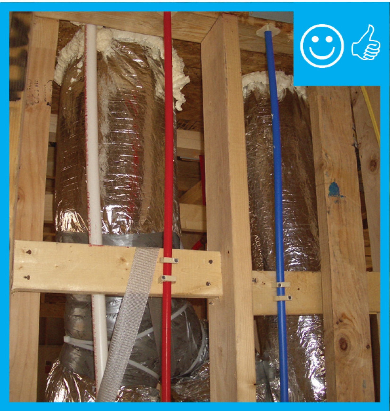
Right – PEX piping speeds hot water directly from the water heater to faucets through the attic in this slab-on-grade home.
Image
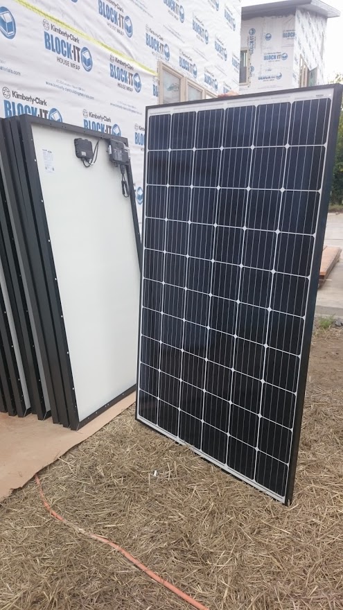
Right – Photovoltaic solar panels are ready for installation on the roof of a DOE Zero Energy Ready certified home.
Image
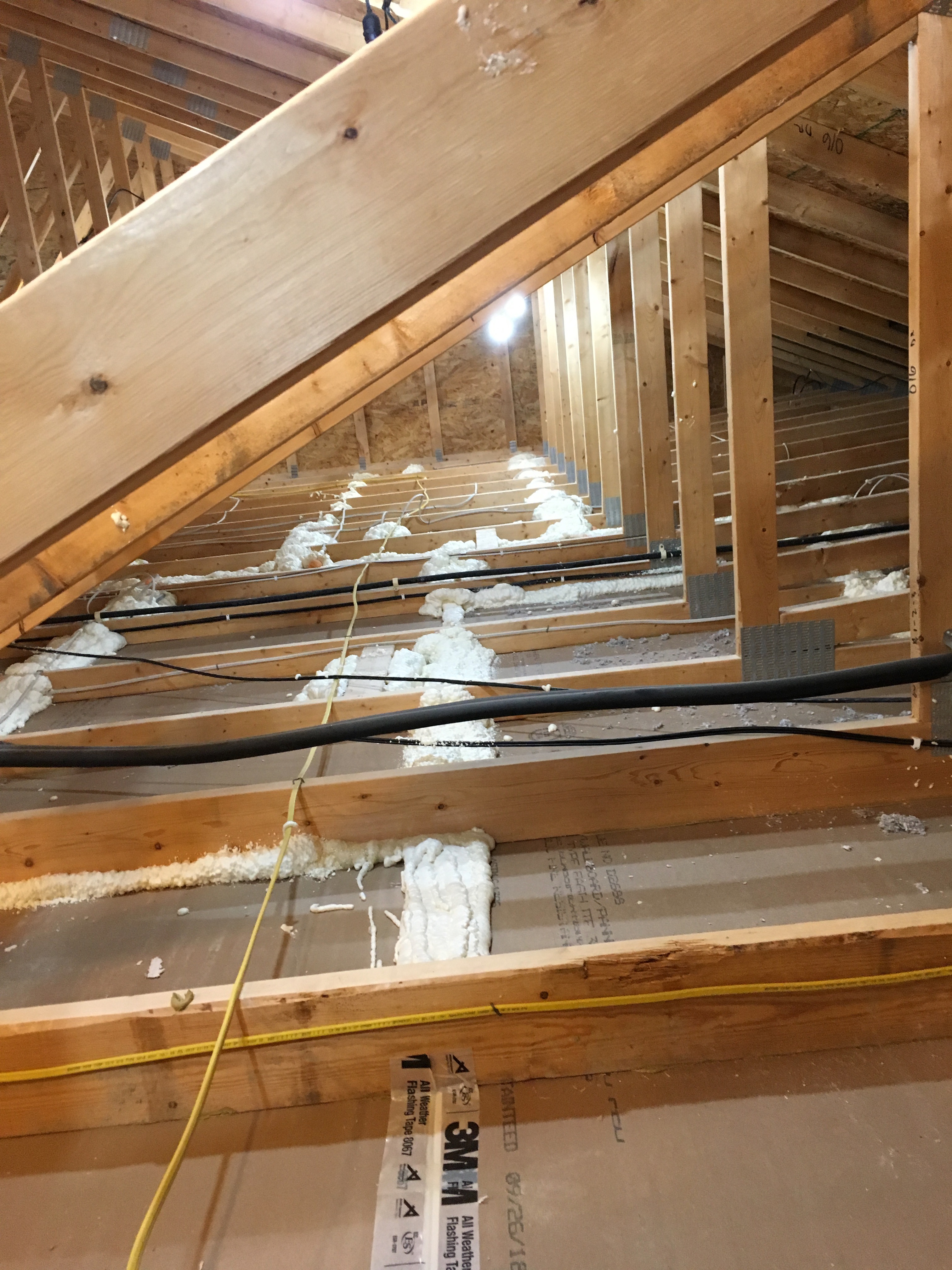
Right – Plastic tenting increases the height of the insulation above ducts that are located in the attic.
Image
Image
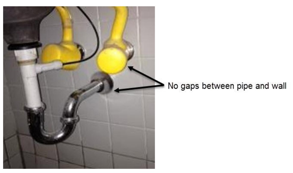
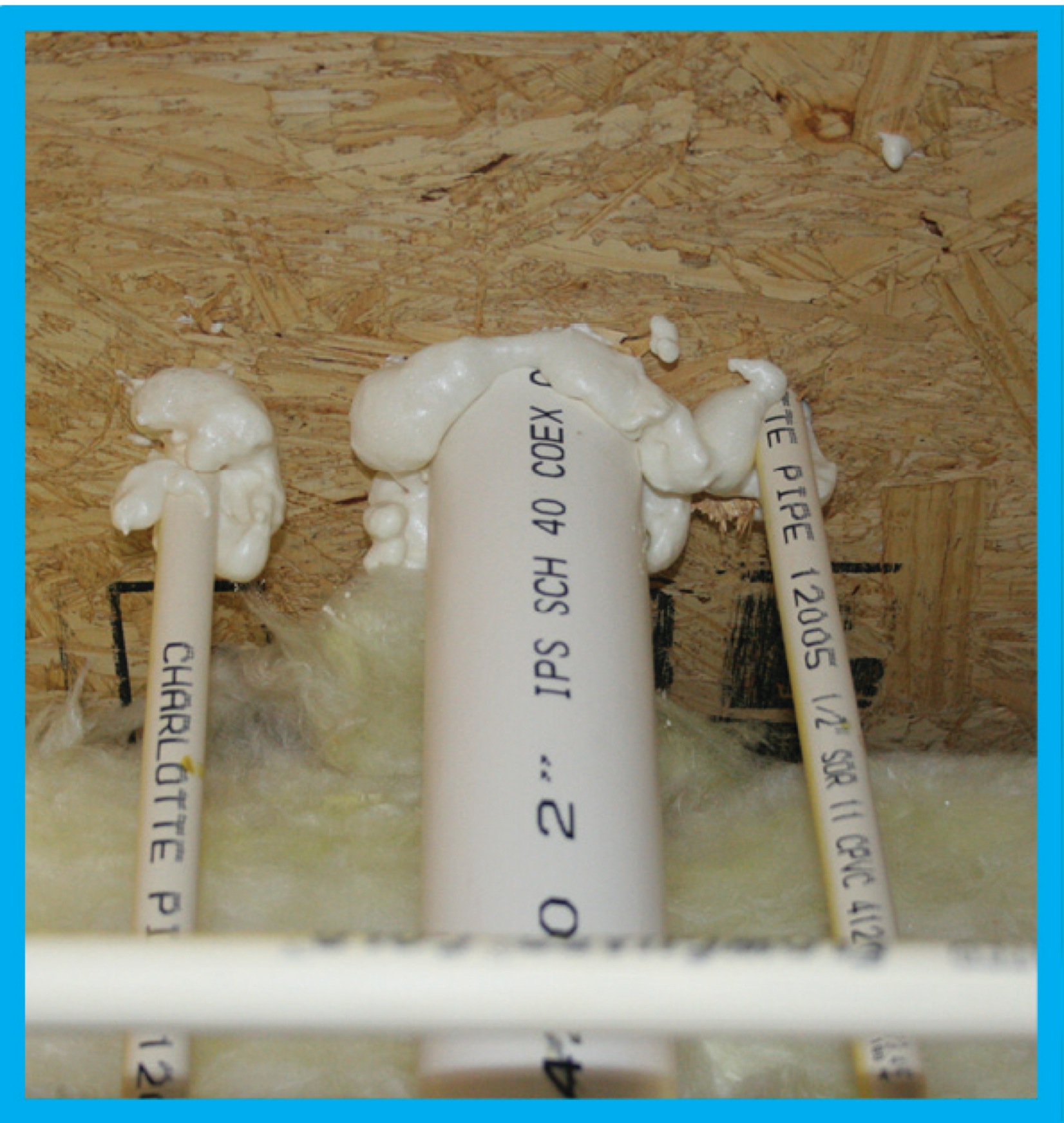
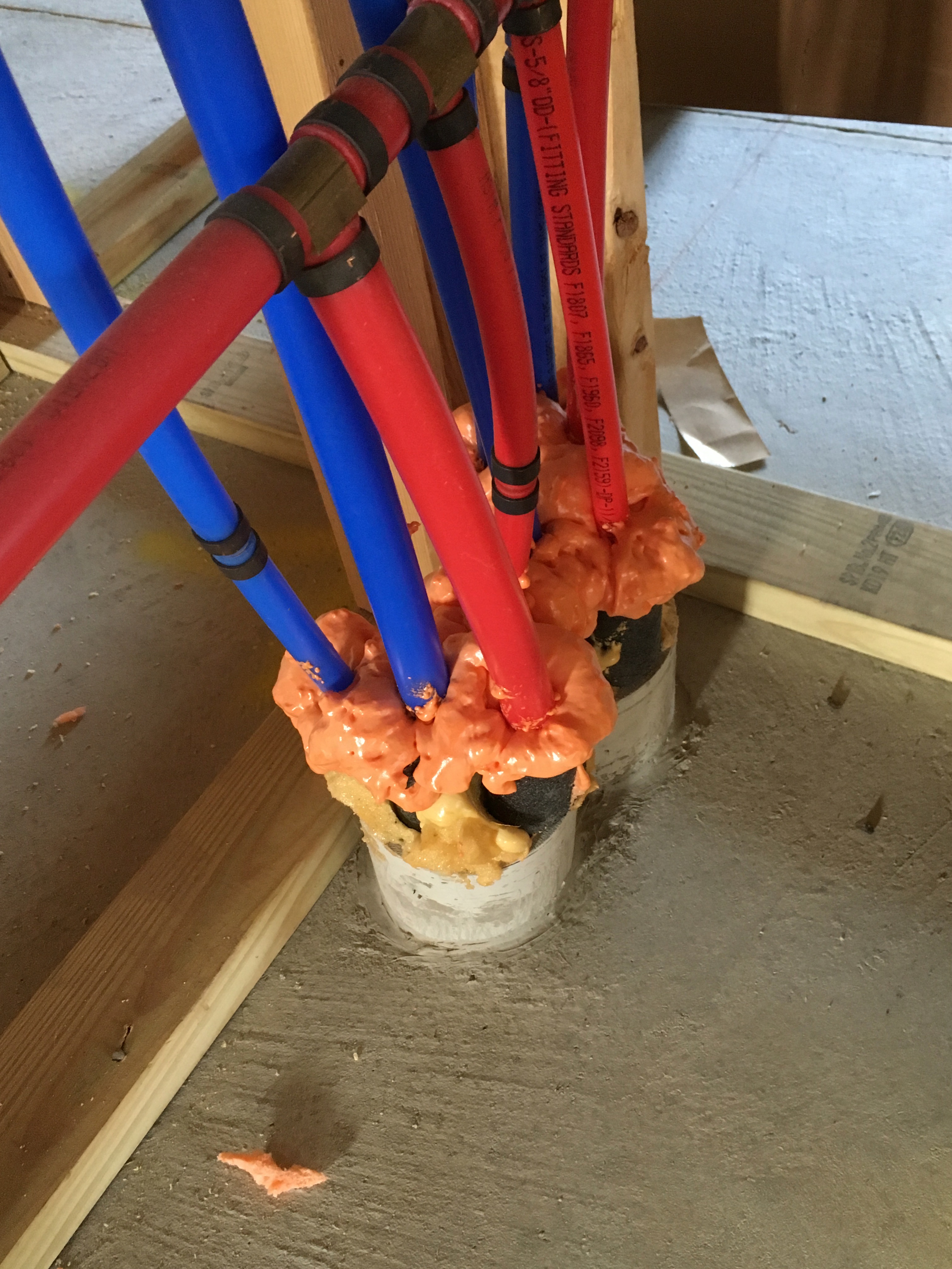
Right – Plumbing pipes have flanges that are sealed to the wall with caulk to prevent pest entry
Image
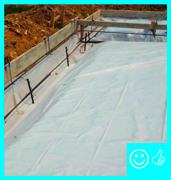
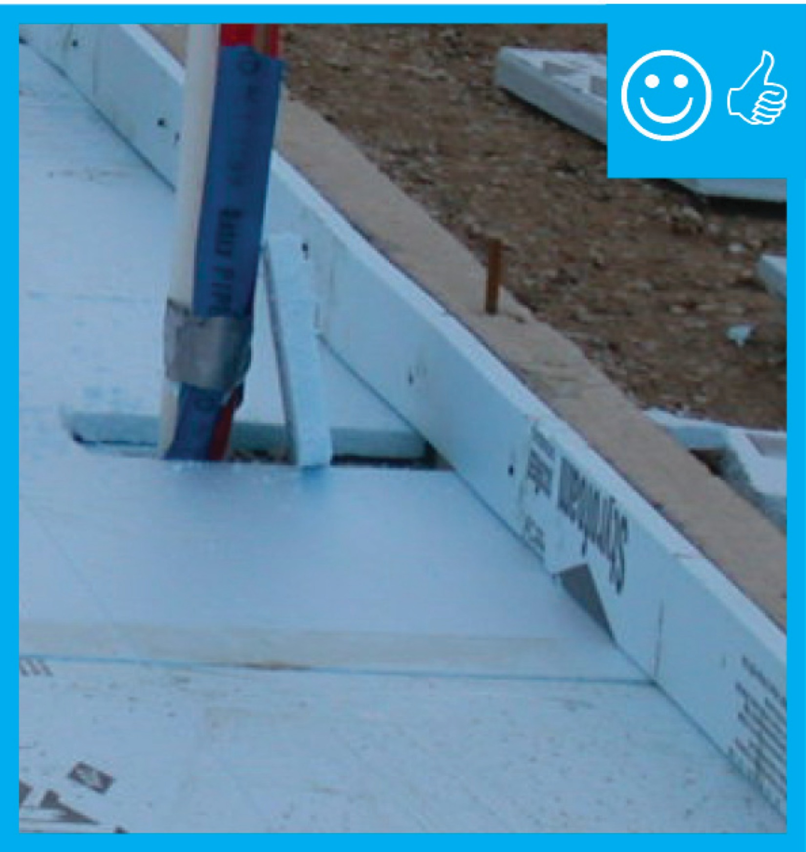
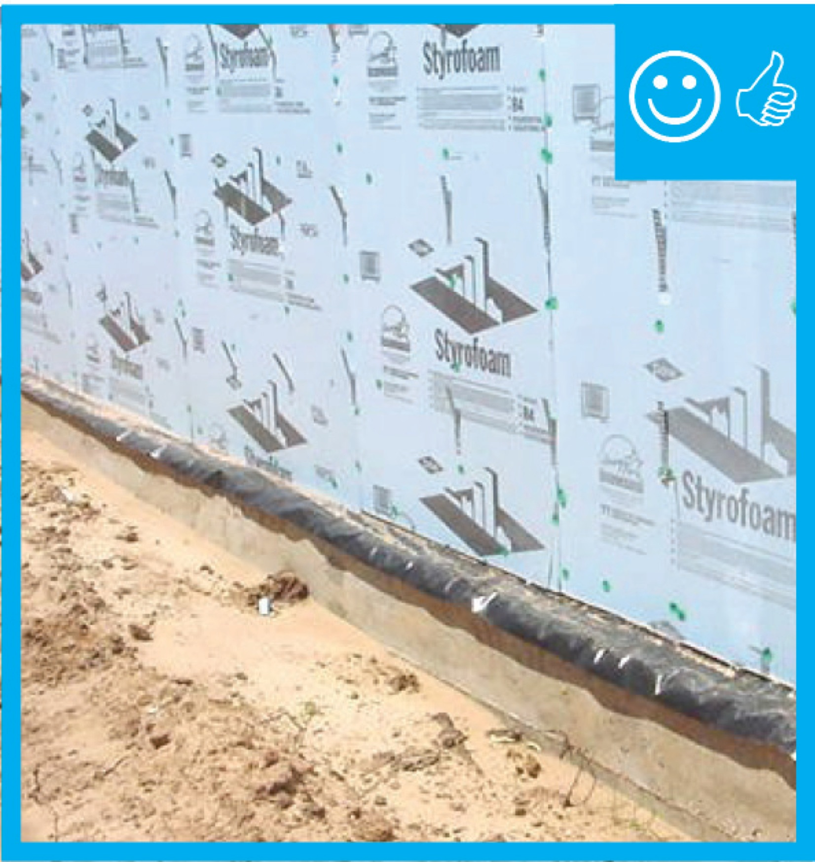
Right – Polyethylene sheeting completely covers the aggregate and the footing with no tears or open seams
Image

Right – Polyethylene sheeting is laid over aggregate and over footing to provide a capillary break between the ground and the slab and between the footing and the stem wall
Image
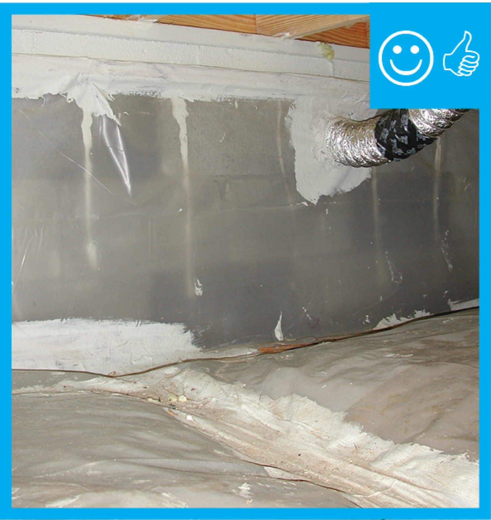
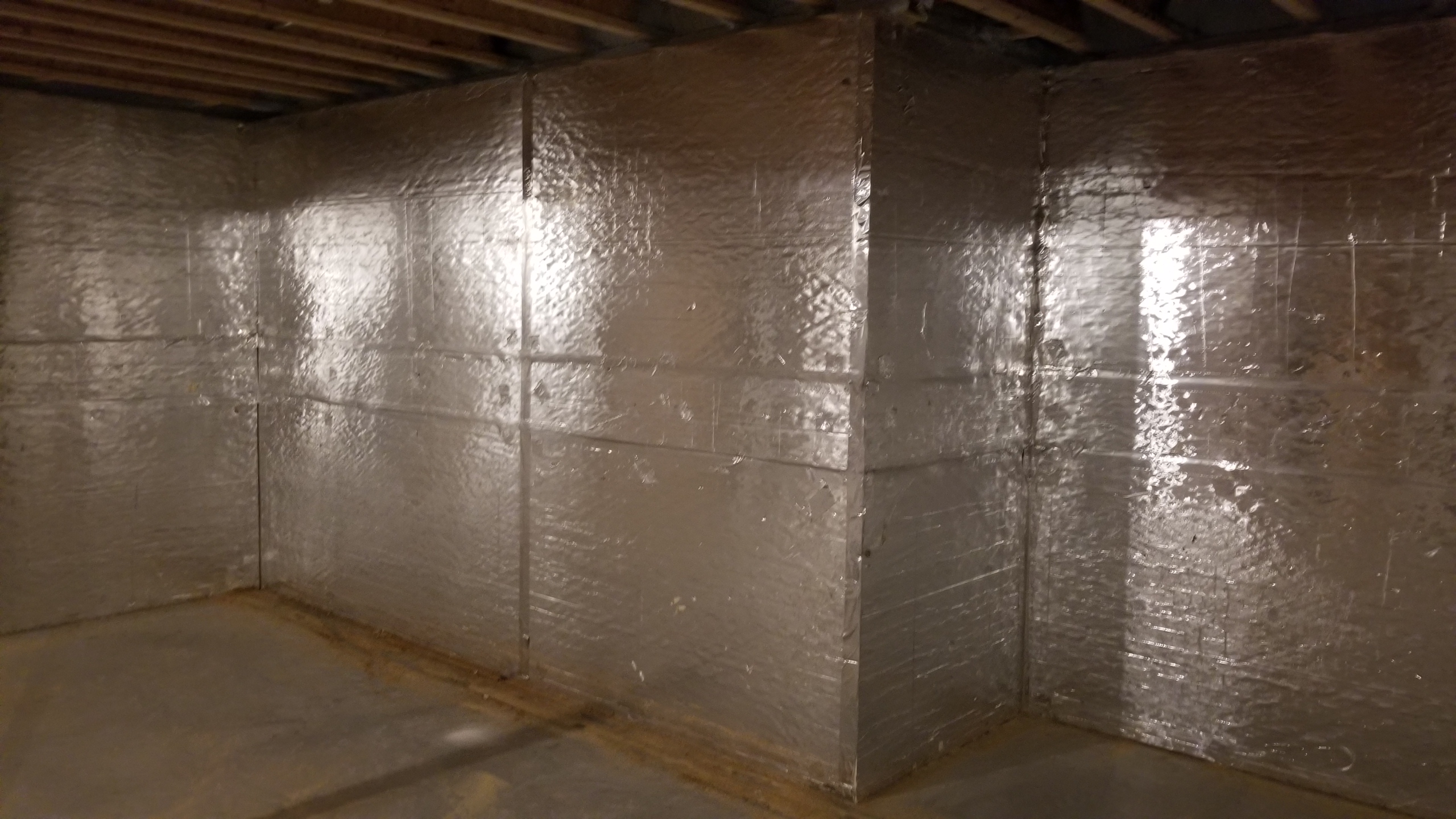
Right – Polyethylene sheeting vapor barrier is installed and sealed to the crawlspace walls with mastic
Image
Image
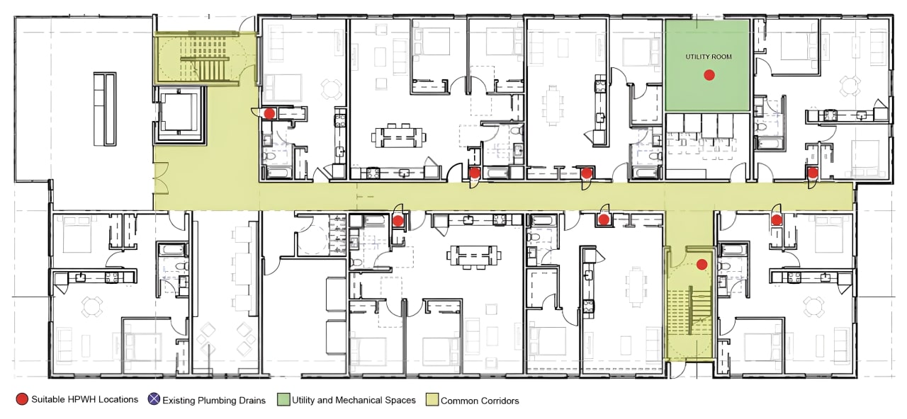
Right – Possible Heat Pump Water Heater Locations on a Multifamily Floorplan including an interior corridor, eight apartments, and meeting rooms
Image
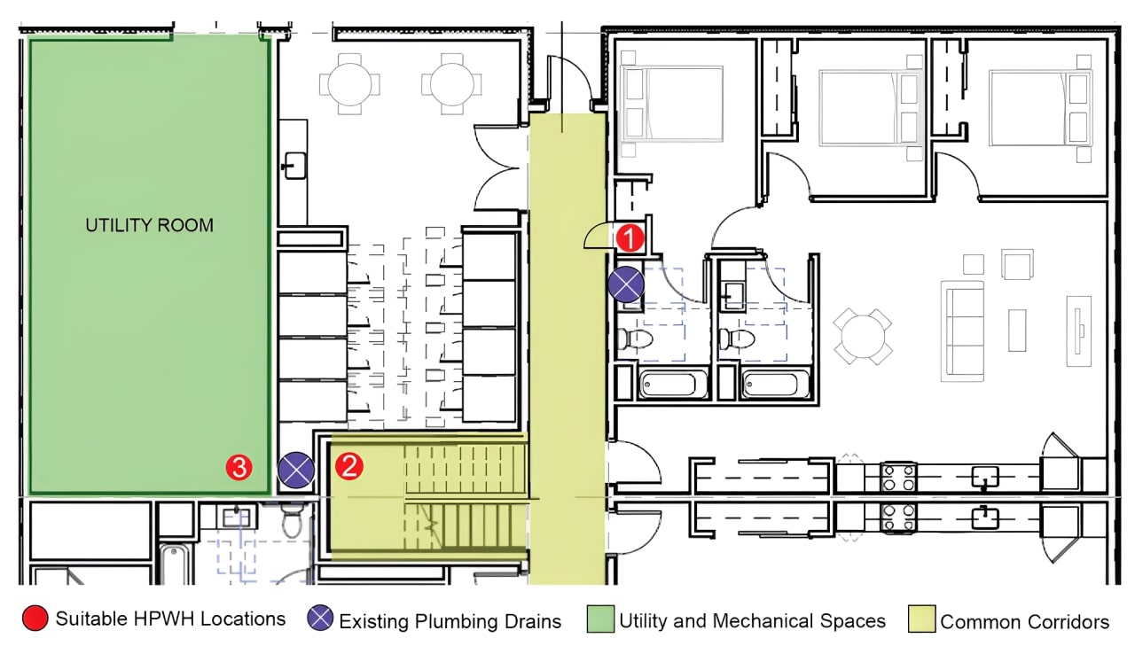
Right – Possible Heat Pump Water Heater Locations on a Multifamily Floorplan including interior corridor closets, under-stair closes, and utility rooms
Image
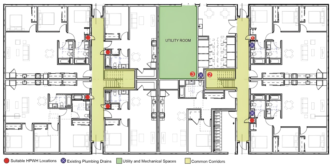
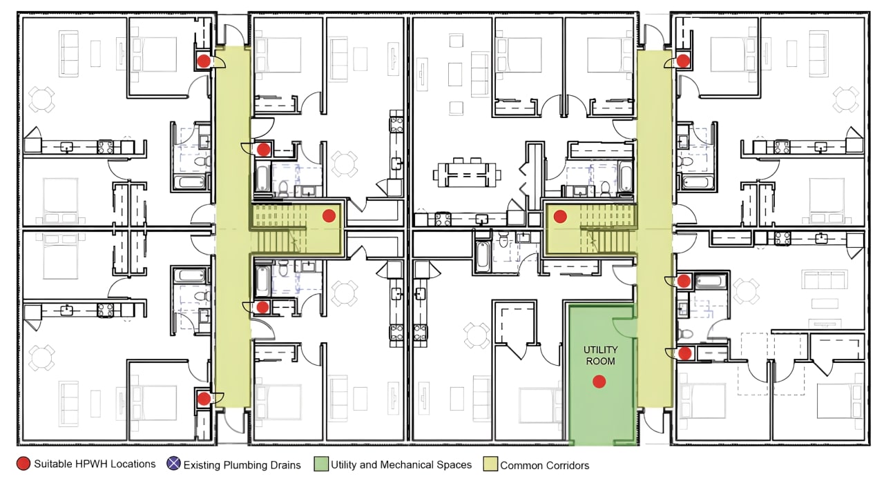
Right – Possible Heat Pump Water Heater Locations on Full Plate Floorplan in a Multifamily Building
Image
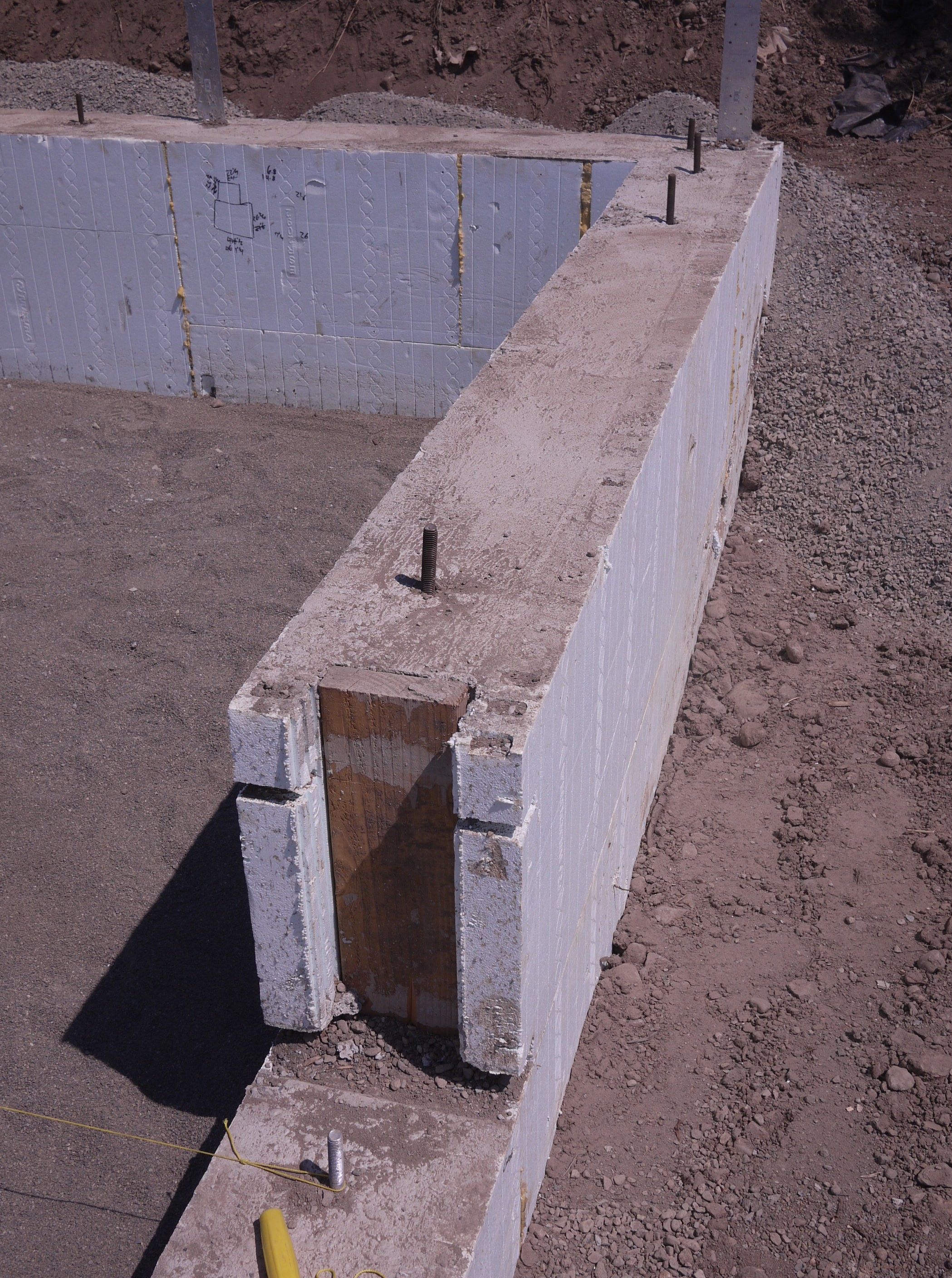
Right – Precast concrete basement walls come to the site with integrated insulation and steel-faced concrete studs.
Image
Right – Prepoured foundation panels with integrated insulation and vapor barrier are installed in place.
Image
Image
Image
Image
Image

Image
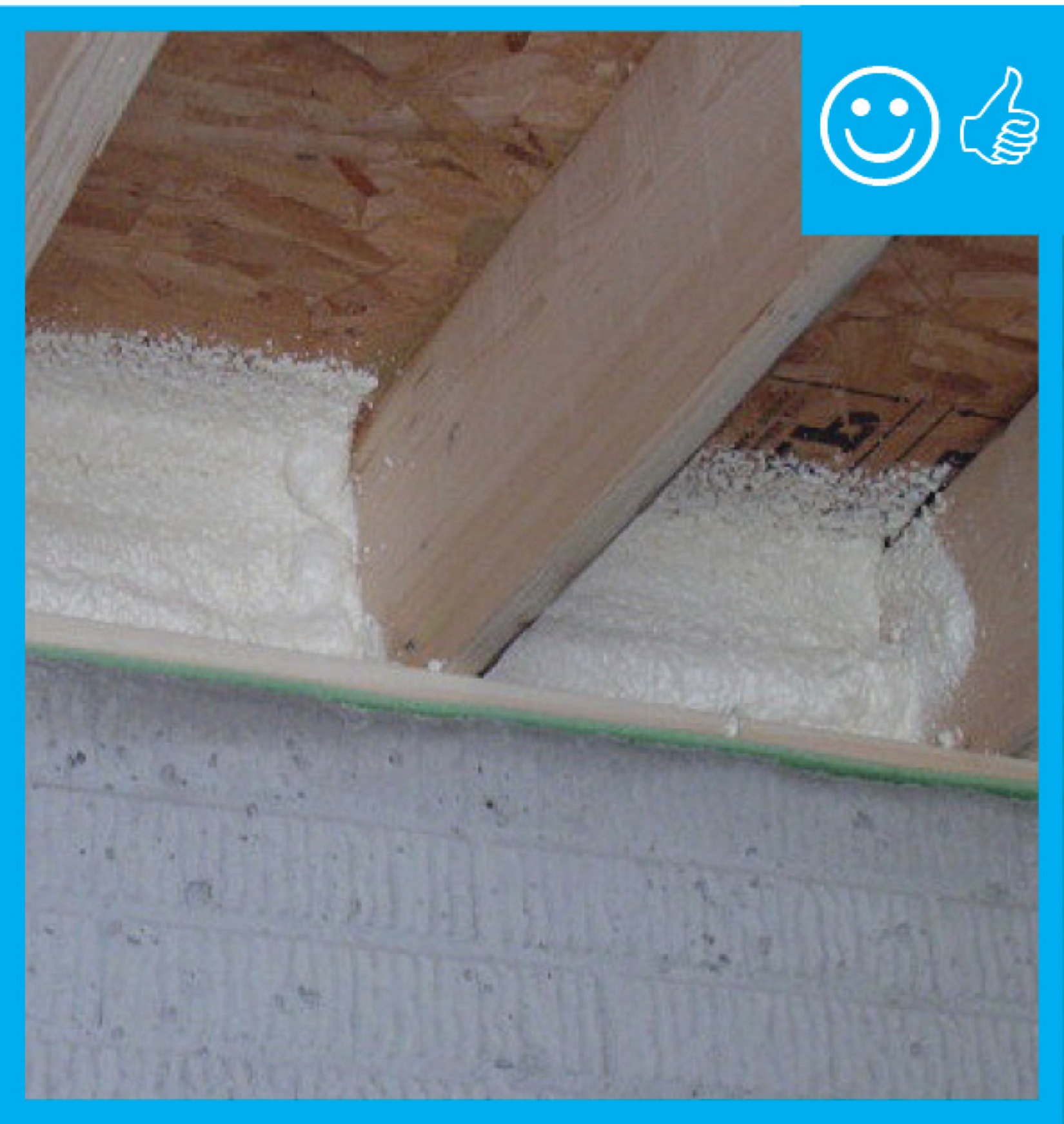
Right – R-20 of XPS and polyiso rigid foam were added on the slab shelf that is part of this precast foundation wall system.
Image
Right – R-23 of blown fiberglass fills the walls and unvented vaulted attic cavities of this marine-climate home while an additional R-20 (4-inches) of graphite-enhanced expanded polystyrene is installed above the roof sheathing.
Image
Right – R-25 of open-cell spray foam lines this new home’s attic ceiling, to protect HVAC ducts from heat and cold.
Image
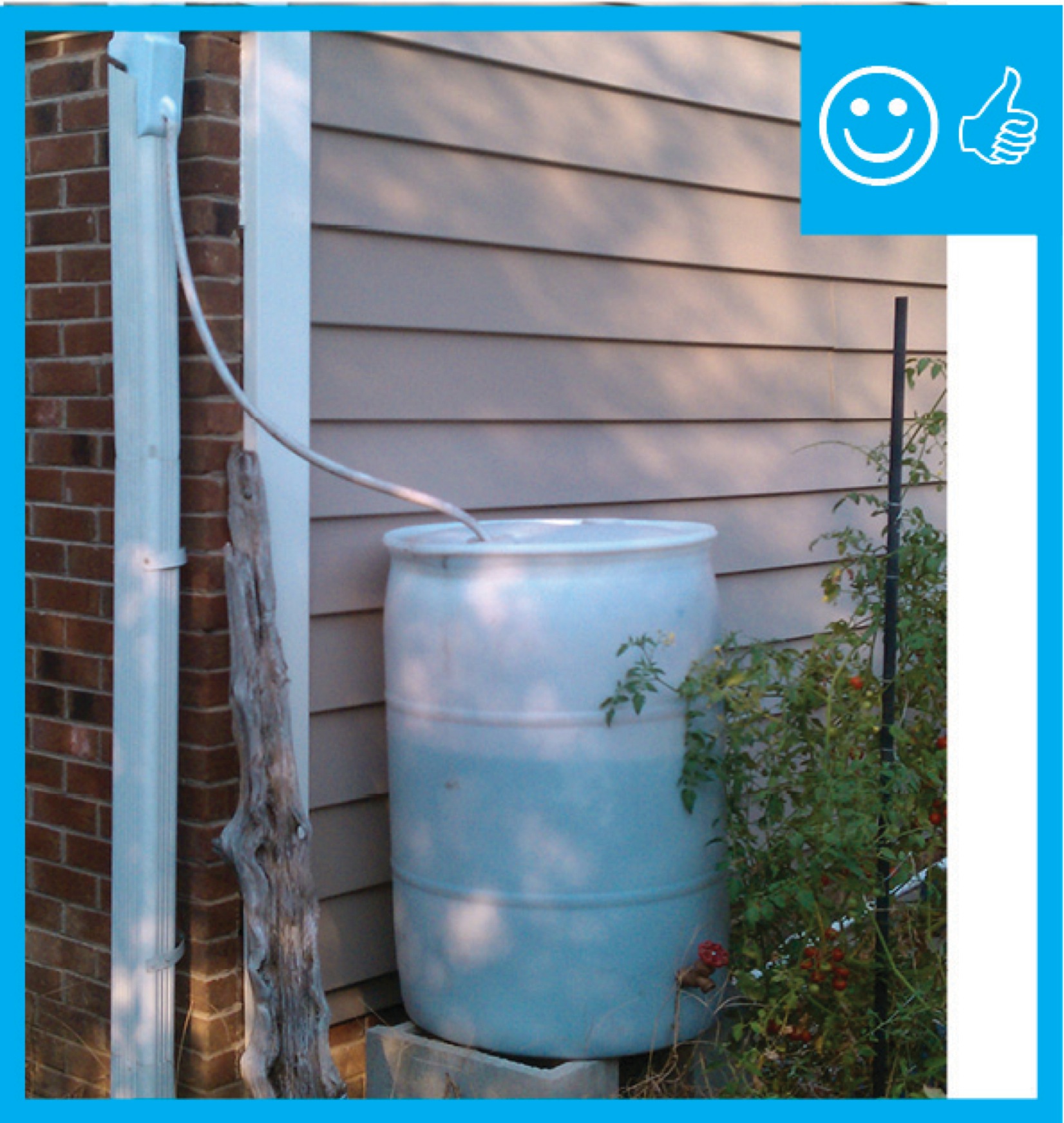
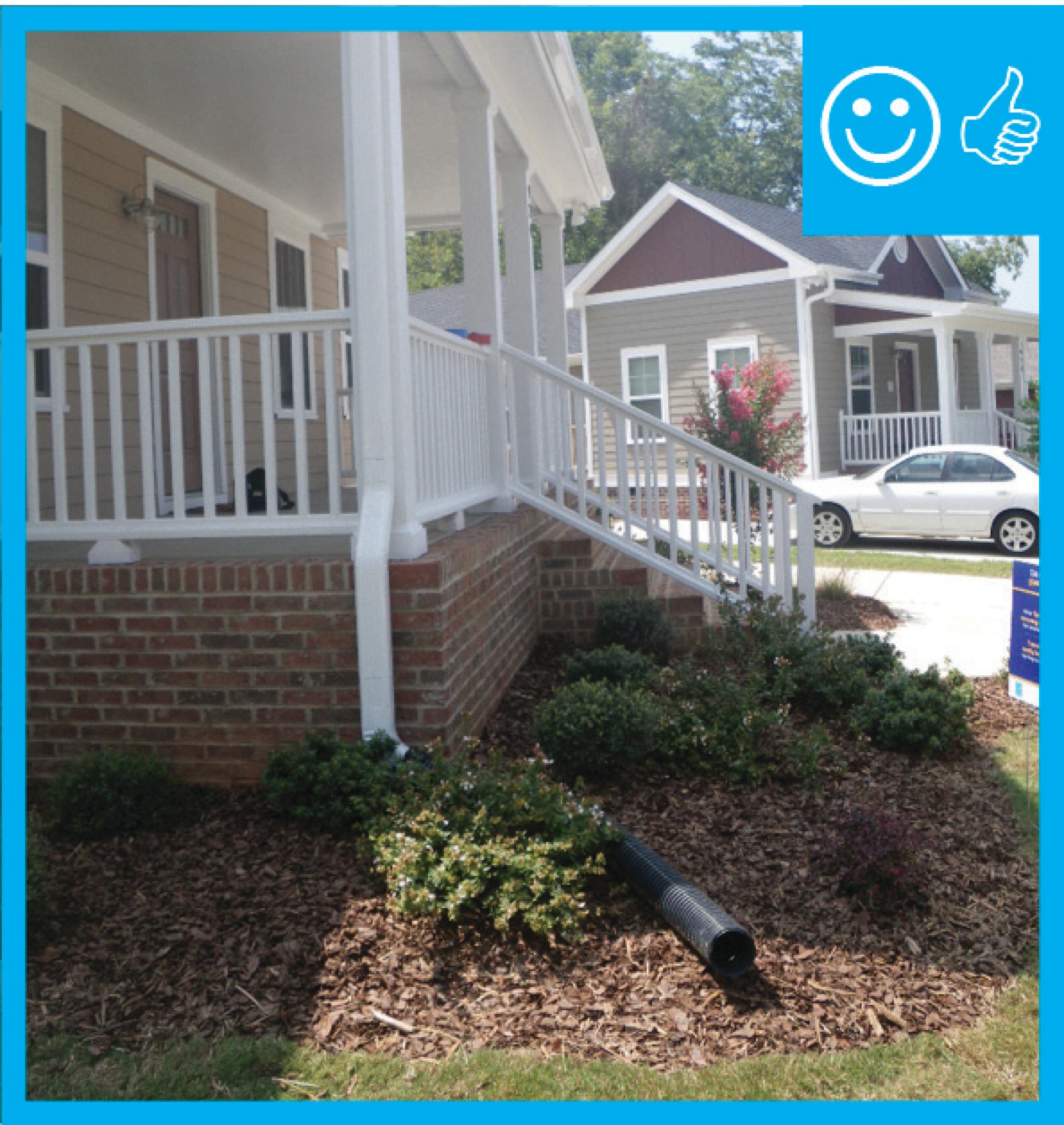
Right – Rain barrel installed with an overflow spout terminating at least 5 feet from foundation
Image
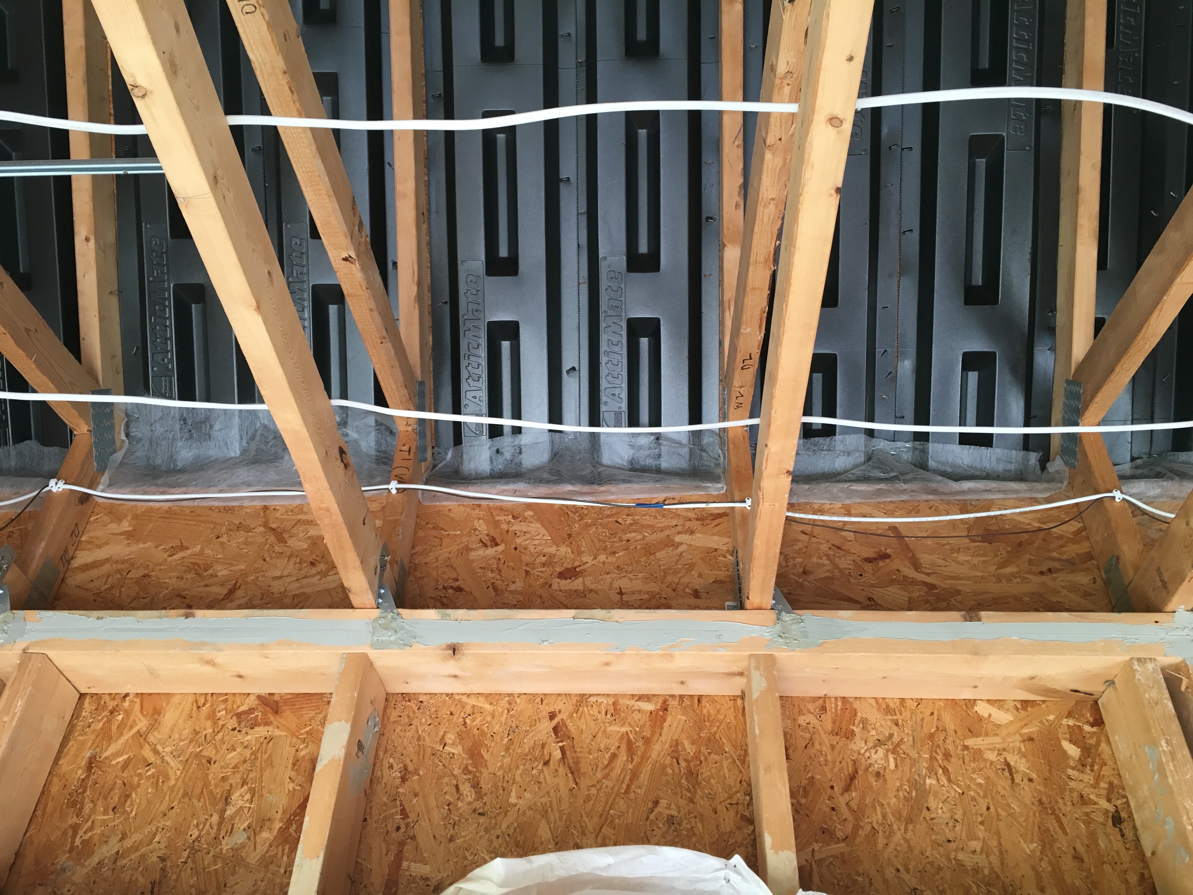
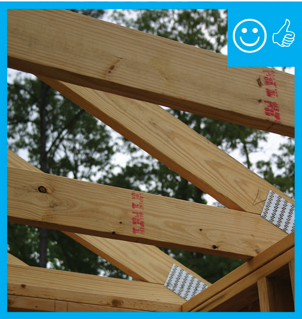
Right – Raised heel trusses allow for full-height insulation over exterior wall top plates.
Image
Right – Raised heel trusses allow room for insulation over the exterior wall top plates, while baffles direct ventilation air to flow above the insulation from the soffit vents to the ridge vents.
Image
Image
Image
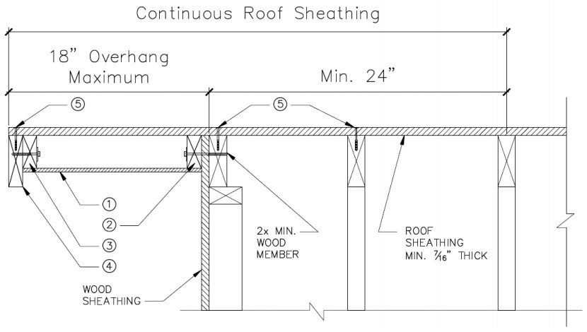
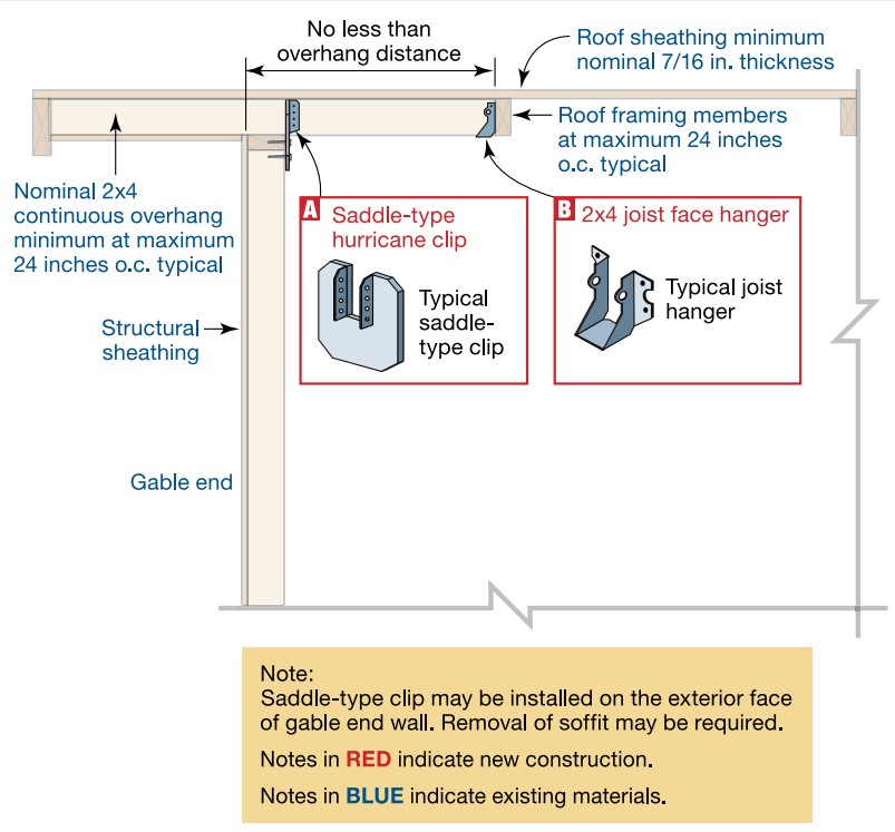
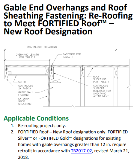
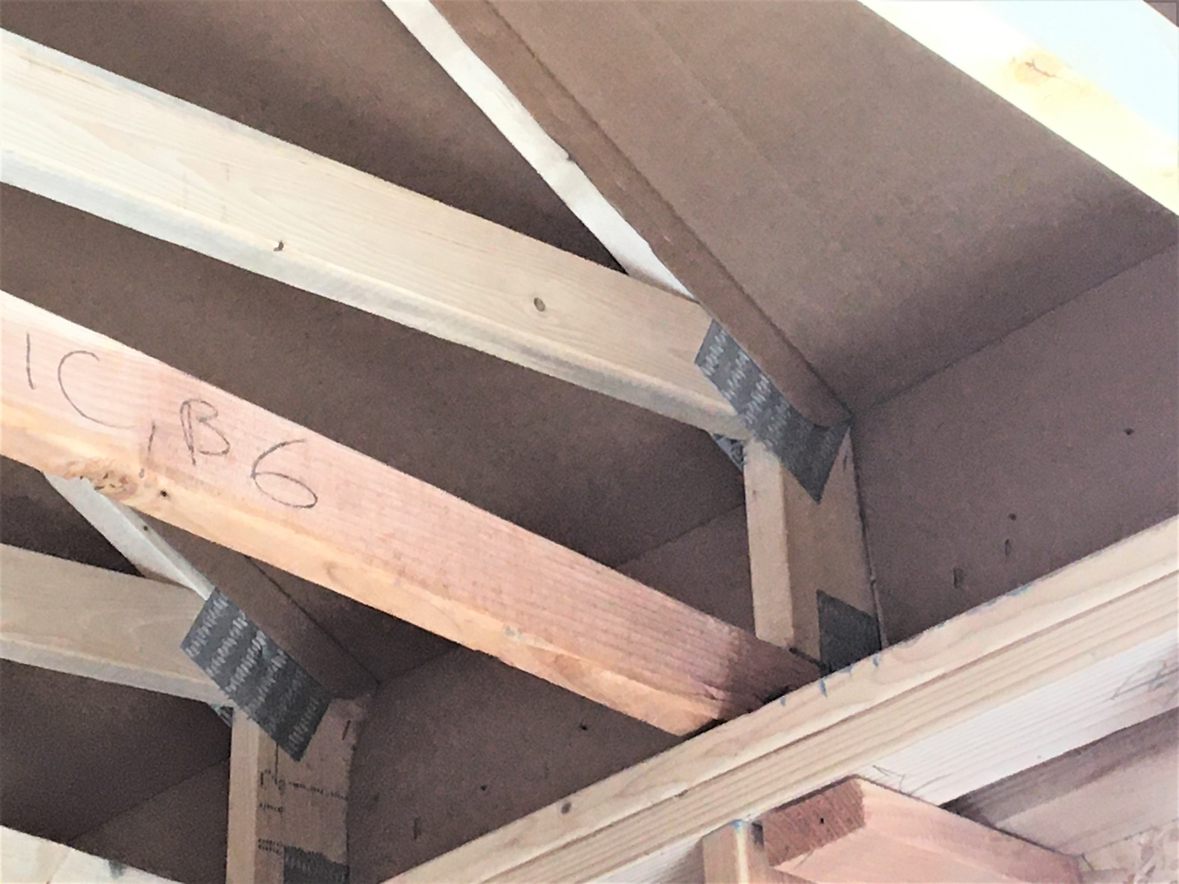
Right – Retrofit Specification for installing roof sheathing an 18-inch gable end overhang
Image
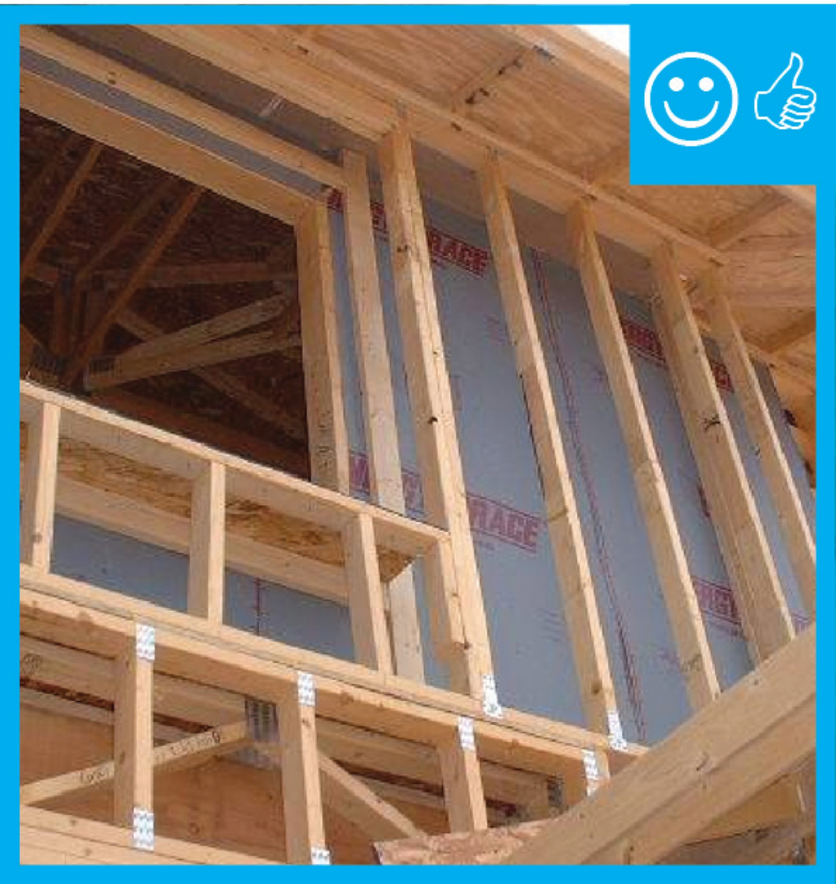
Right – Rigid air barrier installed between double-wall assembly. Inside cavity will be insulated
Image
Image
Image
Image
Image
Image
Image
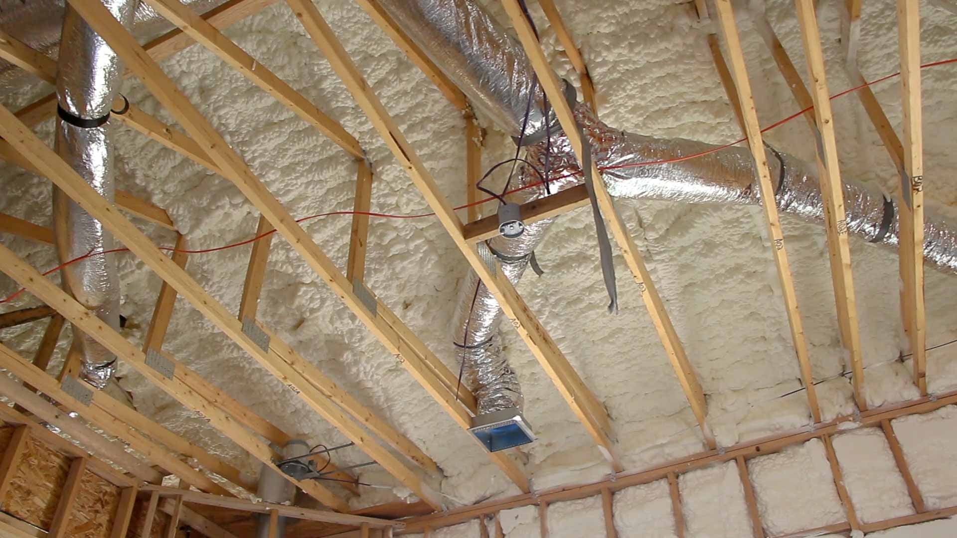
Right – Rigid foam is installed behind HVAC ducts to provide additional insulation to the ducts which are installed within the conditioned space.
Image
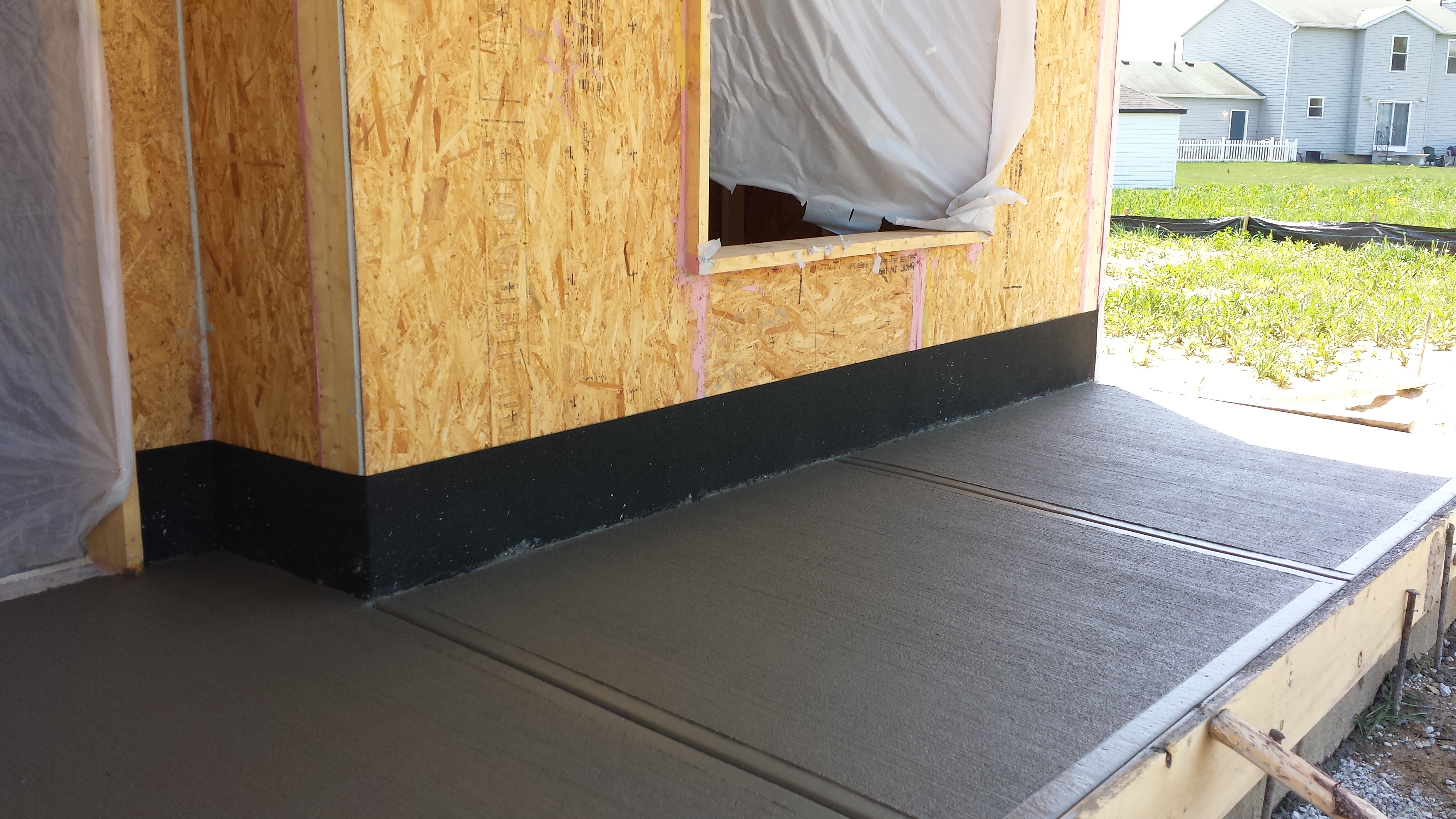
Right – Rigid foam was attached to the tops of the precast foundation walls to form an insulated edge for the floor slab.
Image

Image
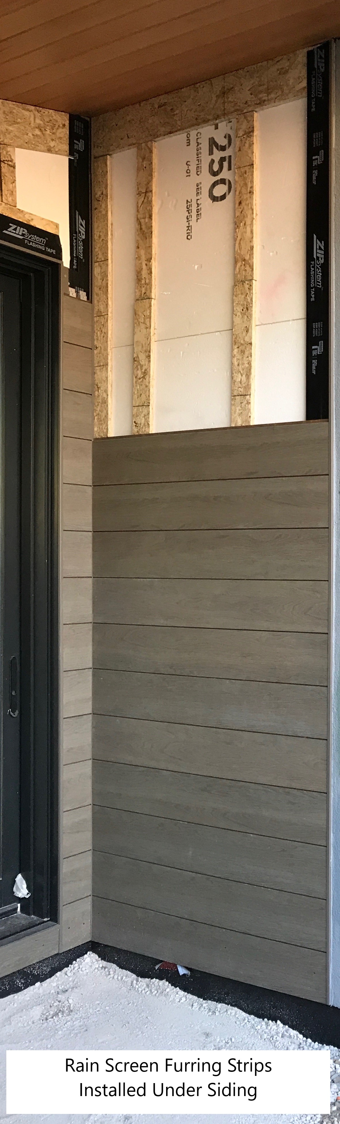
Right – Ripped OSB provides furring strips for a ventilation gap behind the wood siding.
Image
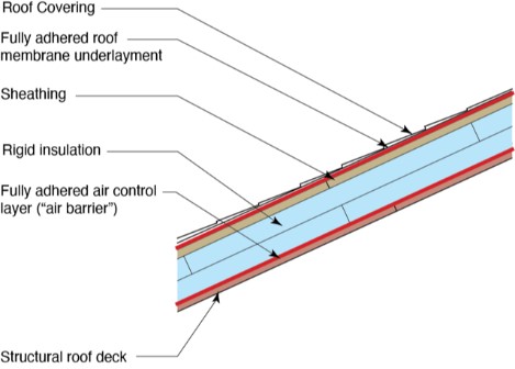
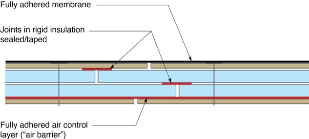
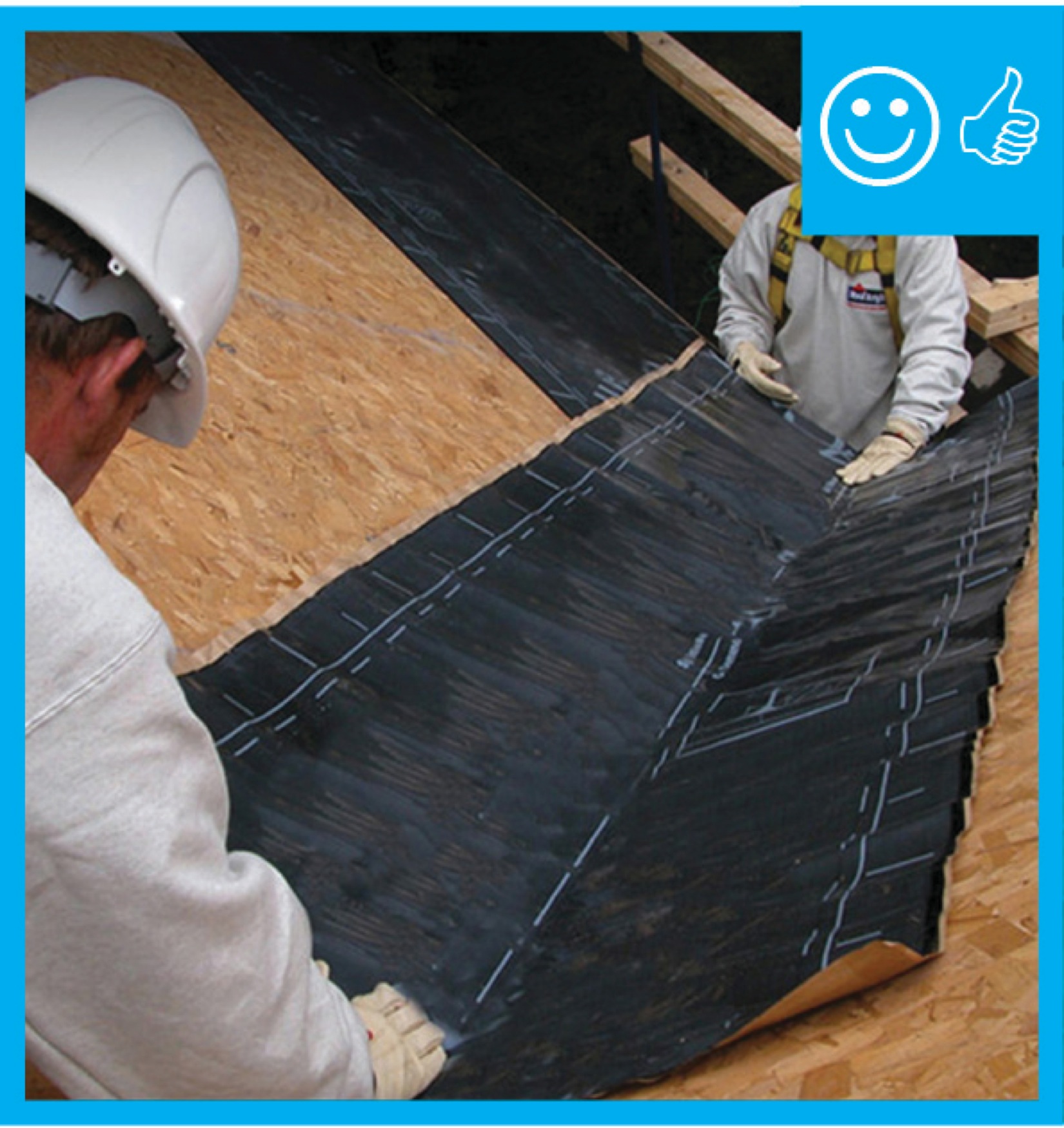
Right – Roof underlayment is fully adhered and roof deck seams are sealed so roof is resistant to high-wind events
Image
Right – Roof underlayment is fully adhered and roof deck seams are sealed so roof is resistant to high-wind events
Image
Image

Image
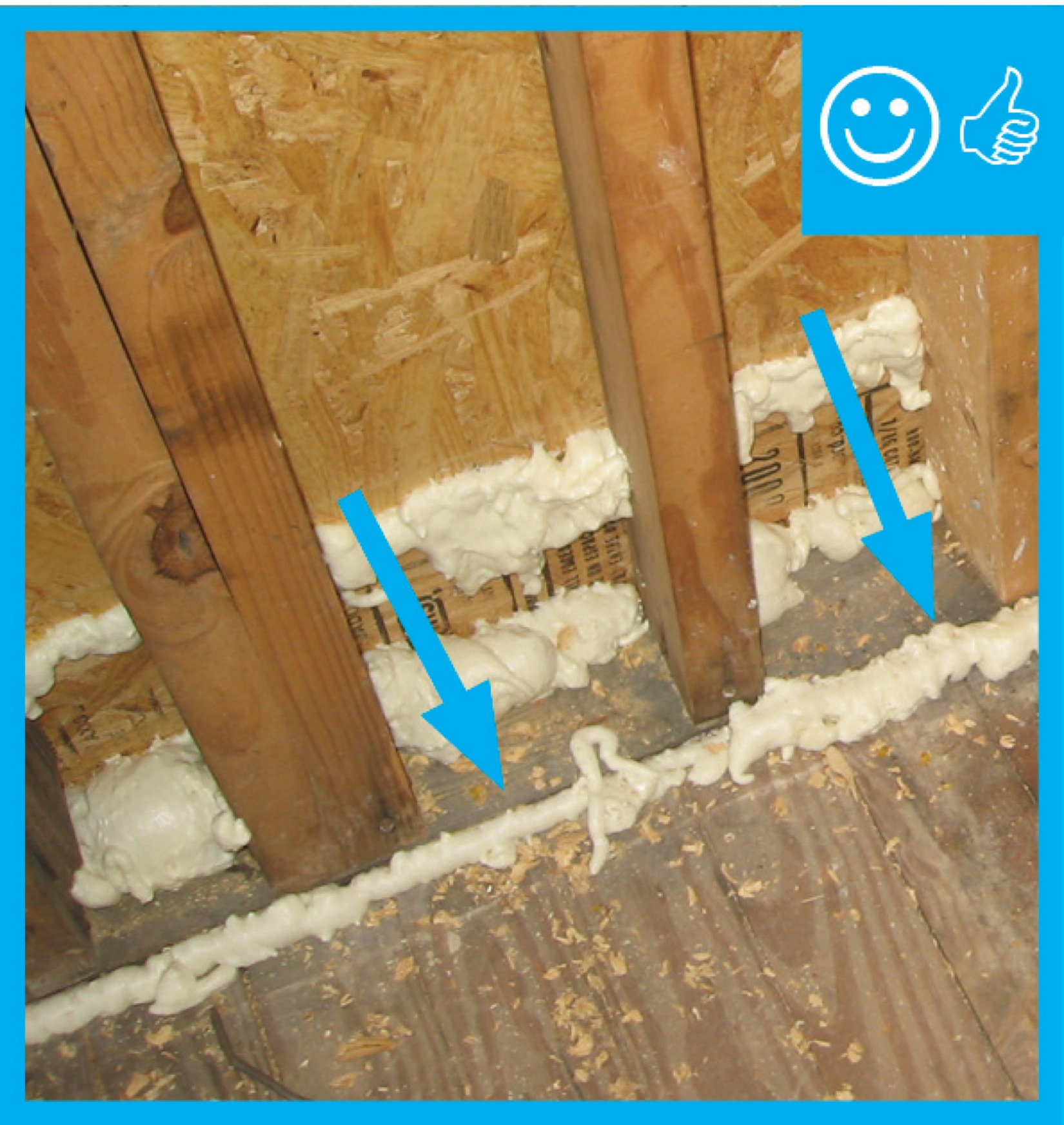
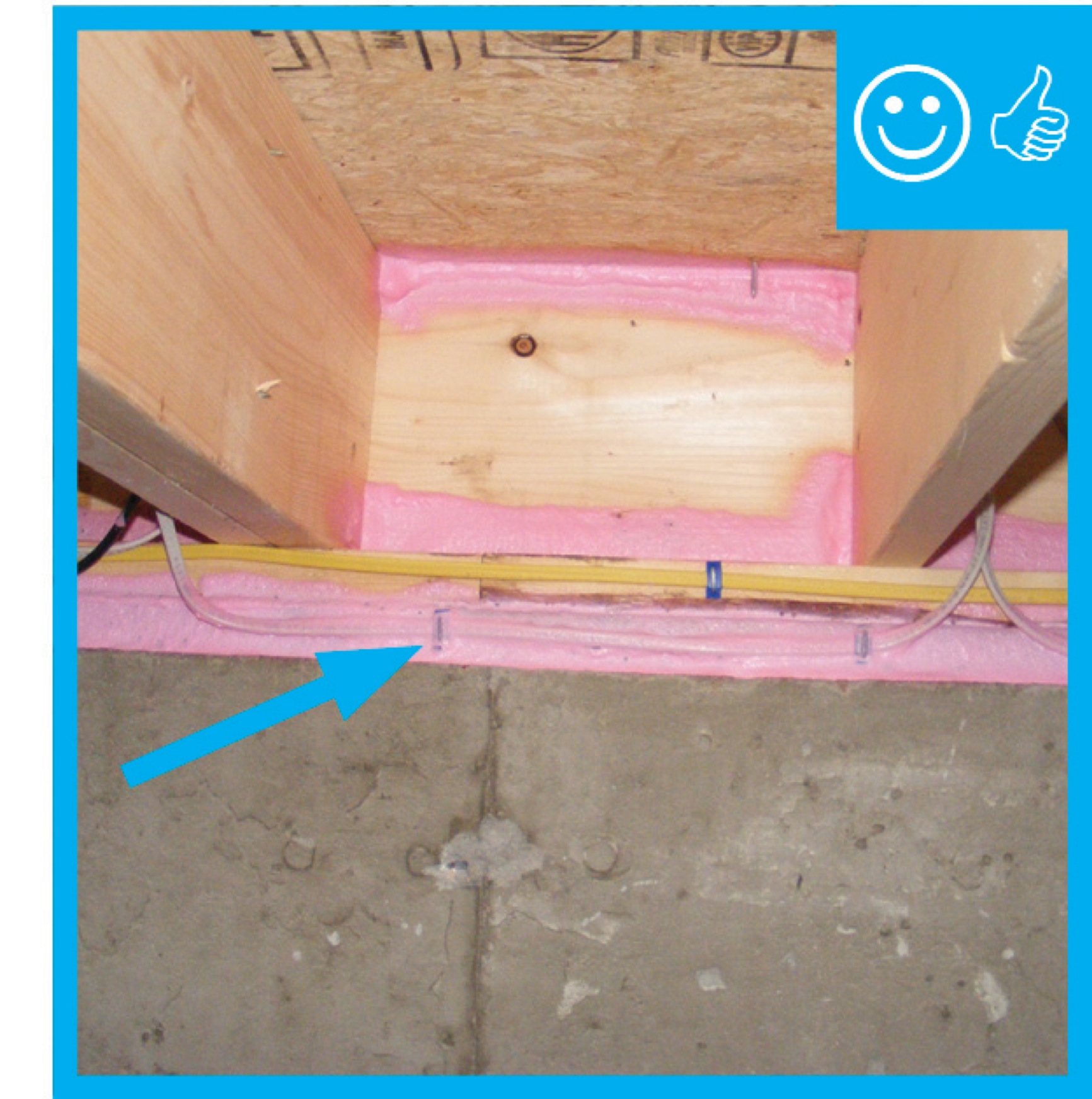
Right – Several potential sources of air leakage into the attic have been air sealed; canned spray foam was used to seal around duct boots, along seams in the drywall, and along top plates.
Image

Right – Sheathing extends to rafters adding strength to soffit, baffles keep attic insulation from vent to maintain air flow
Image

Right – Sheathing, rigid foam, and windows are installed in the factory for these factory-constructed wall panels.
Image
Image
Image
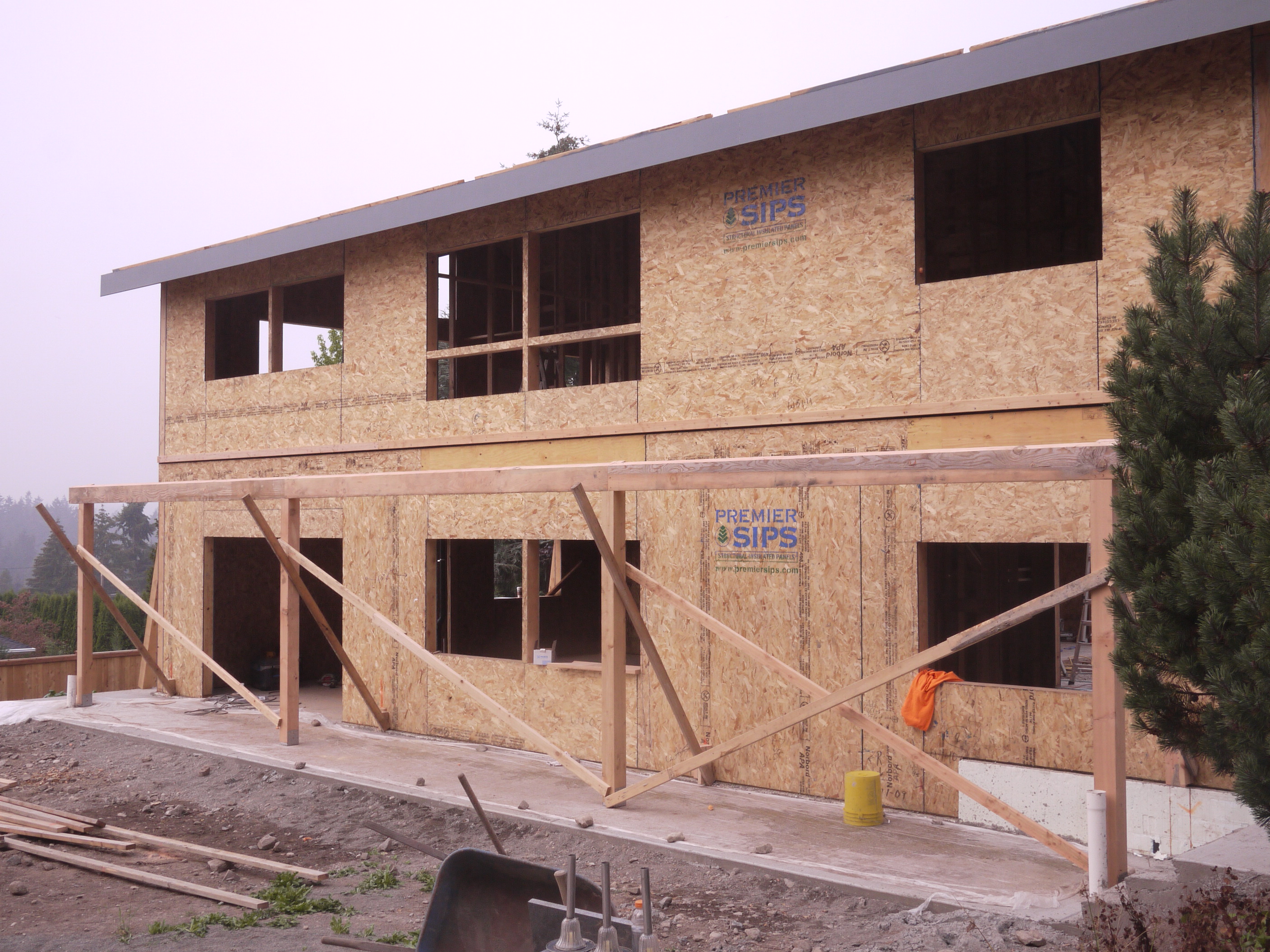
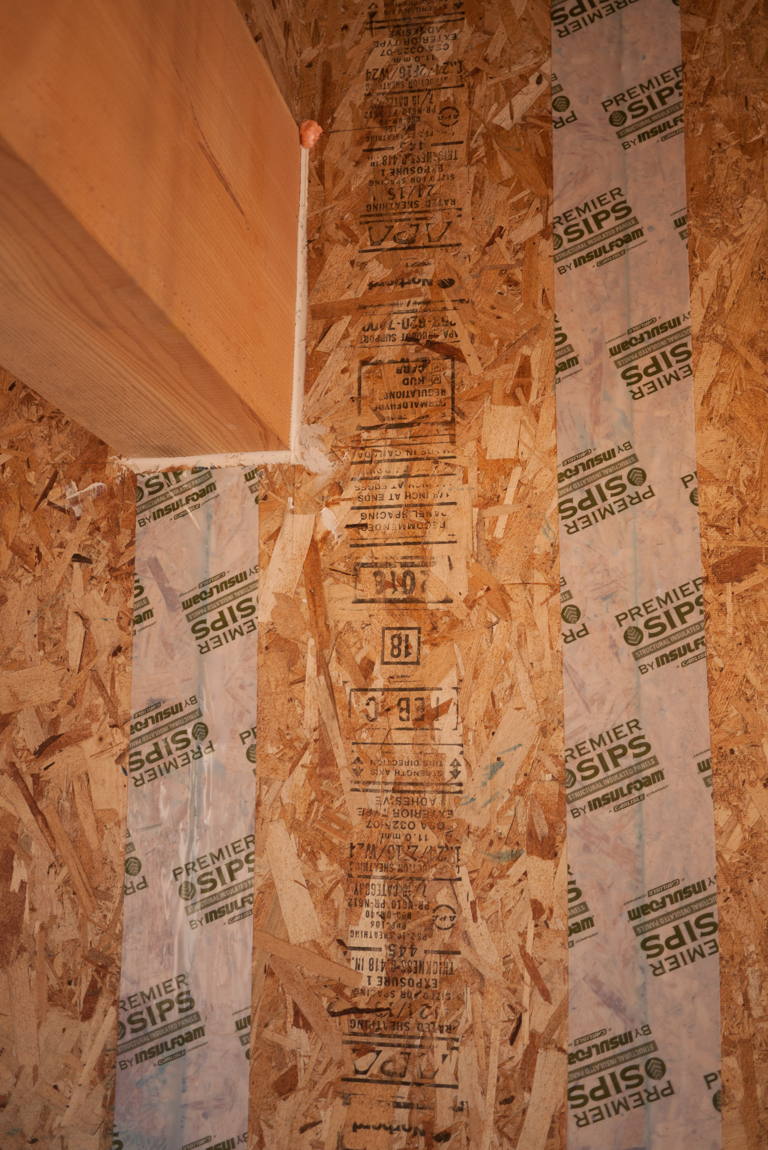
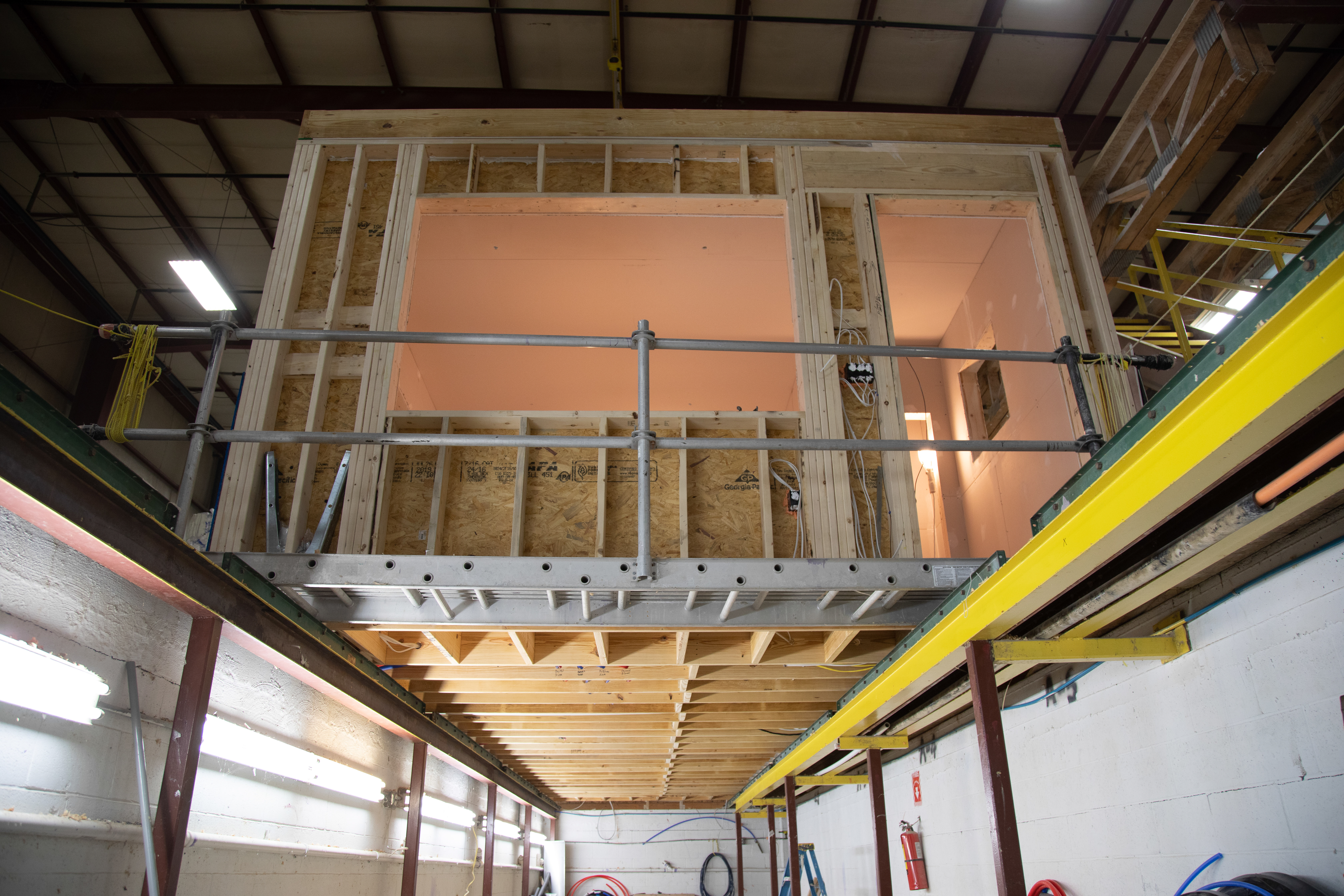
Right – SIP panels assemble quickly on site to provide sturdy walls and a roof that needs few interior supports so there is great flexibility in the layout of interior spaces.
Image
Image

Image
Image
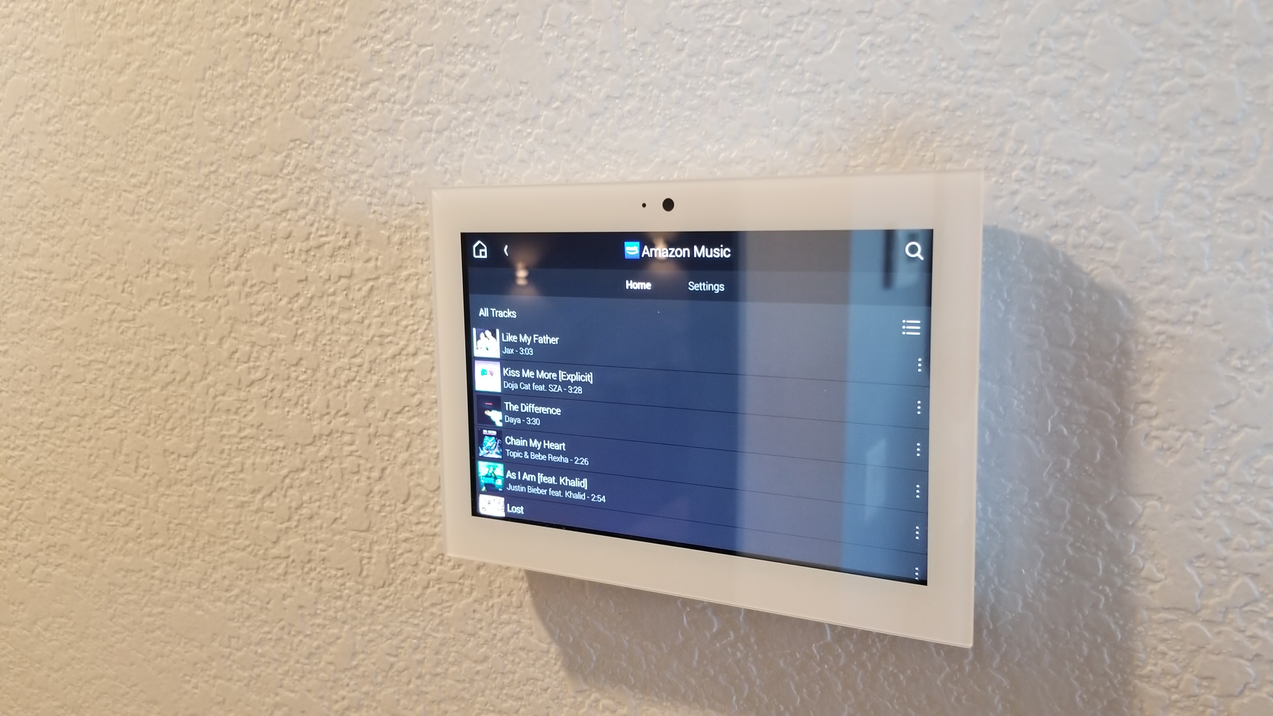
Right – Smart equipment for homes may include a tablet or touchpad from which the homeowner can control lighting, HVAC, window shades, security, music, and other home automation features.
Image
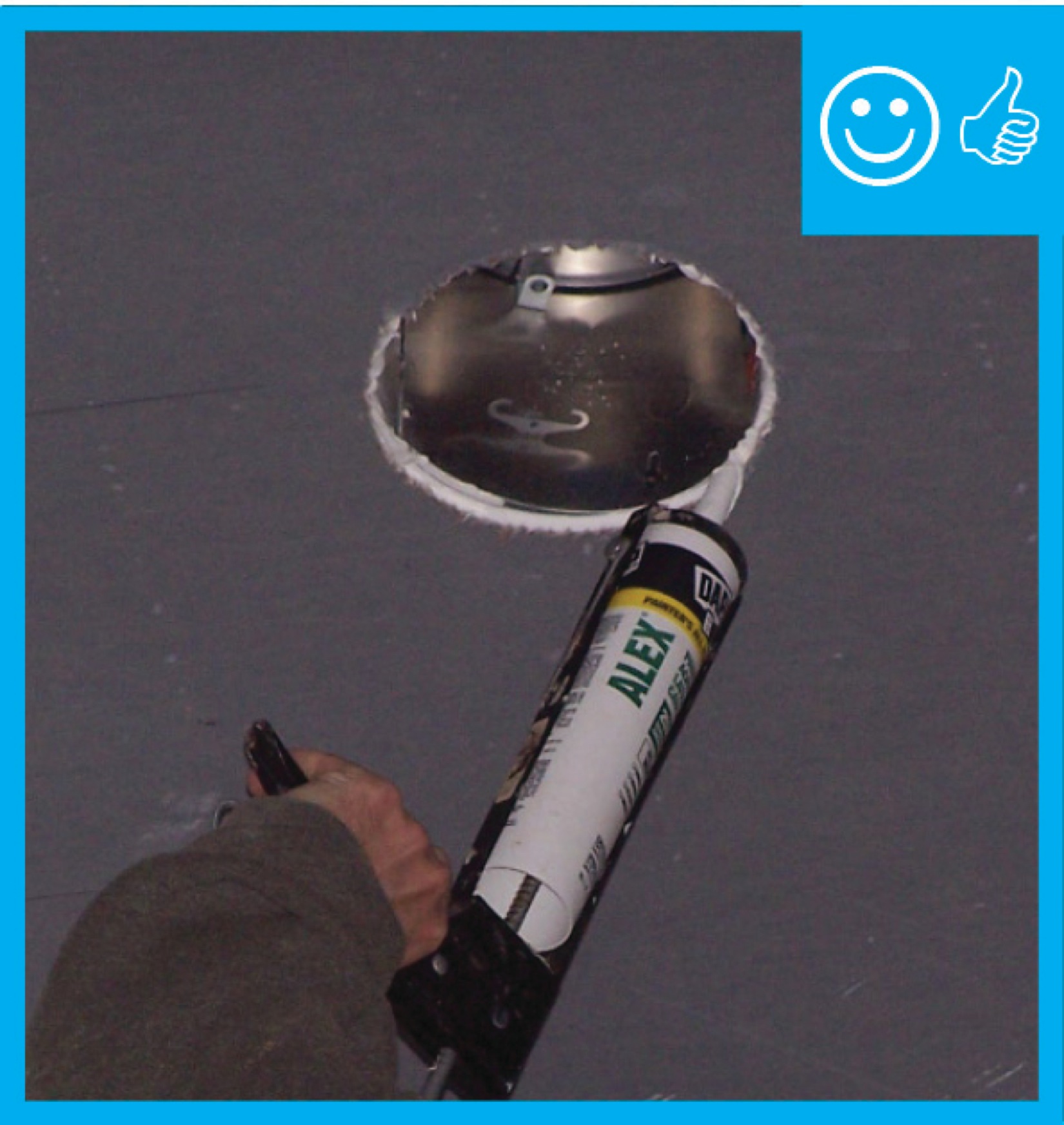
Right – Some tape is pressure sensitive; a roller is used to apply even pressure to ensure full adhesion.
Image
Right – Space was provided next to the electric meter for home’s solar and home energy management tracking electronics.
Image
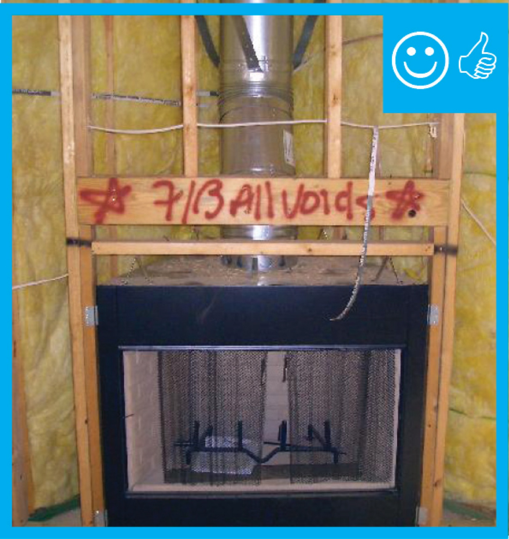
Right – Spray foam air seals and insulates the walls including the walls behind the fireplace and covers the underside of the roof deck of this mixed-dry climate home to provide an insulated attic space for HVAC ducts.
Image
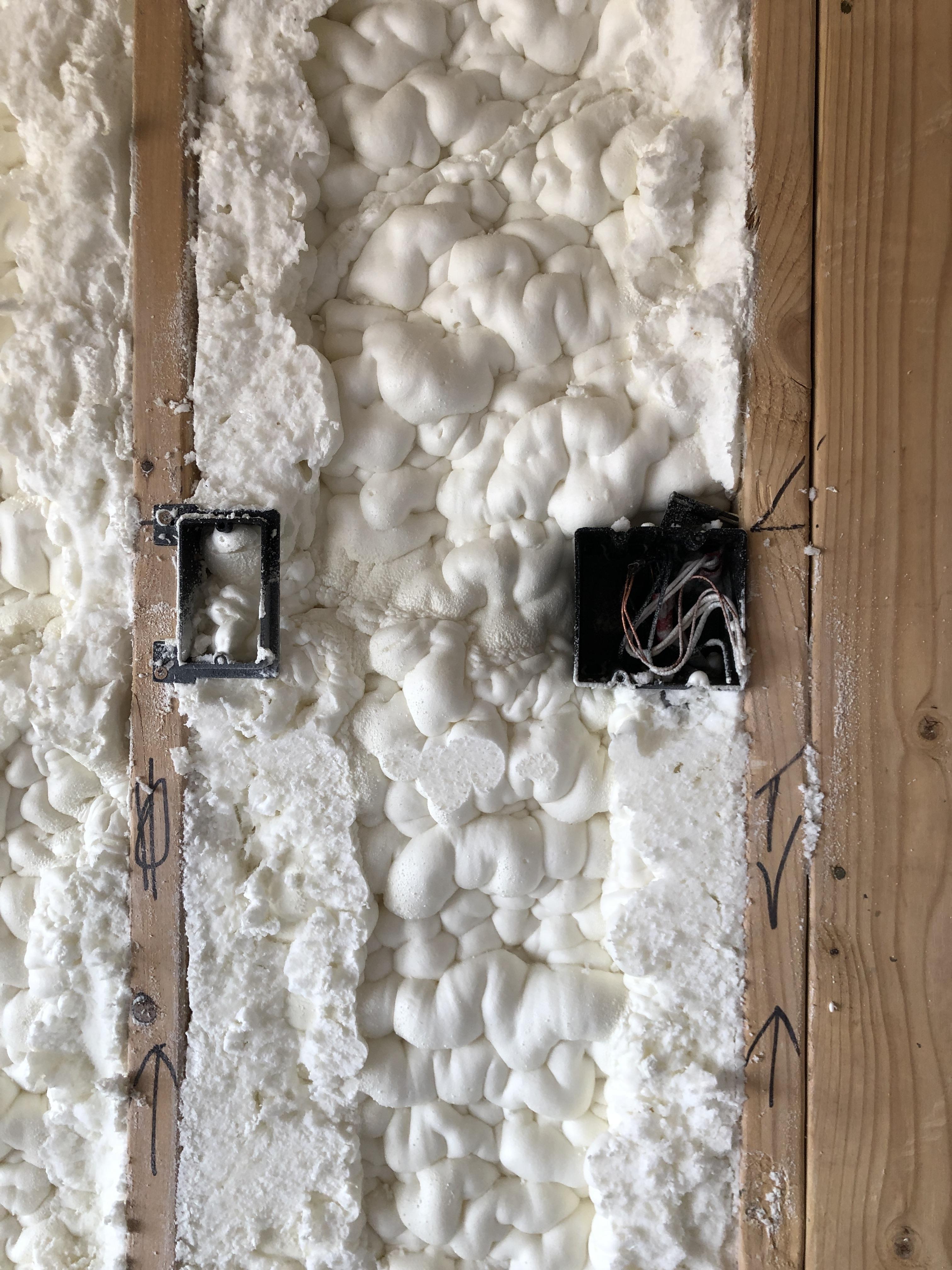
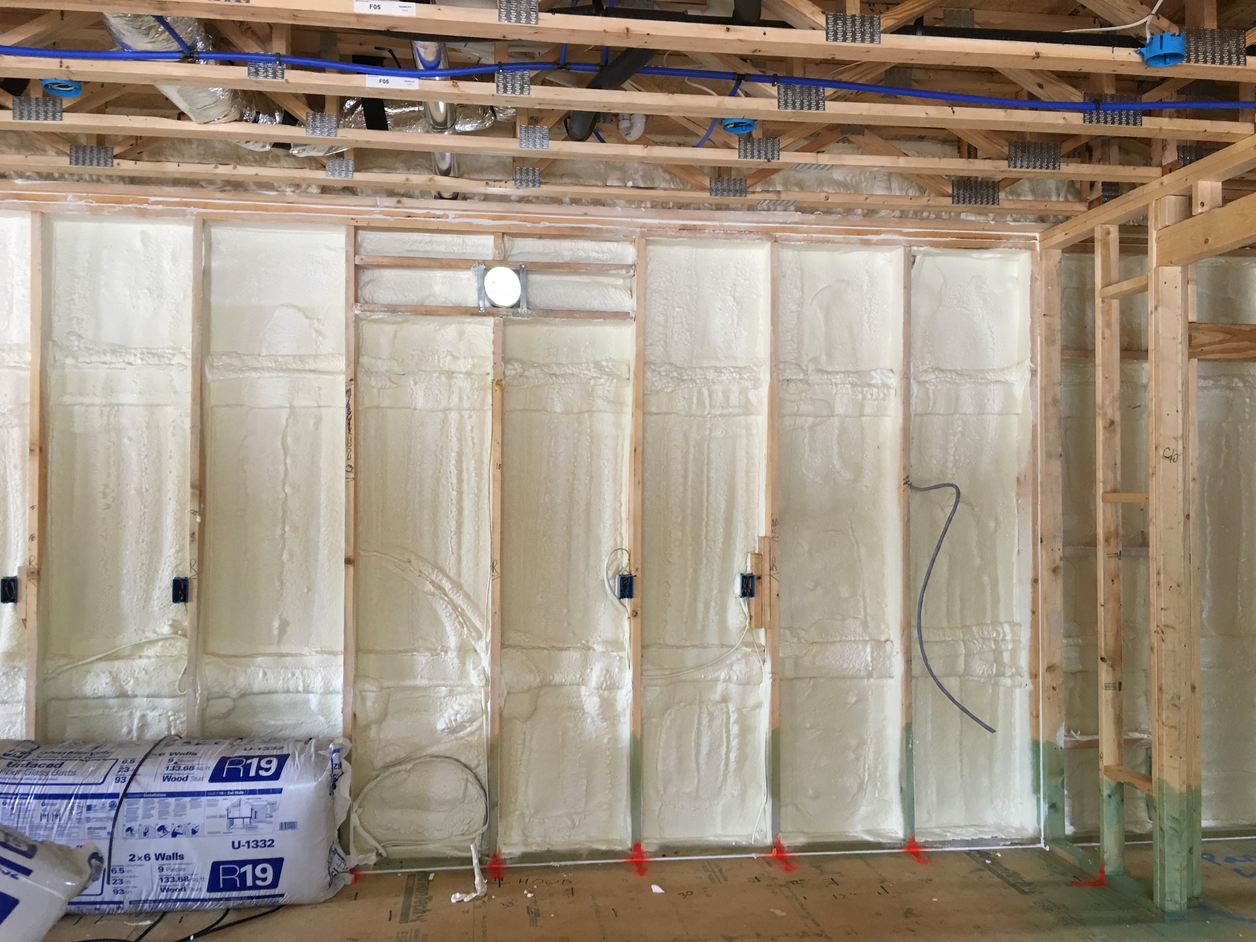
Right – Spray foam completely fills the wall cavities, providing a thorough layer of insulation behind electrical boxes.
Image
Image
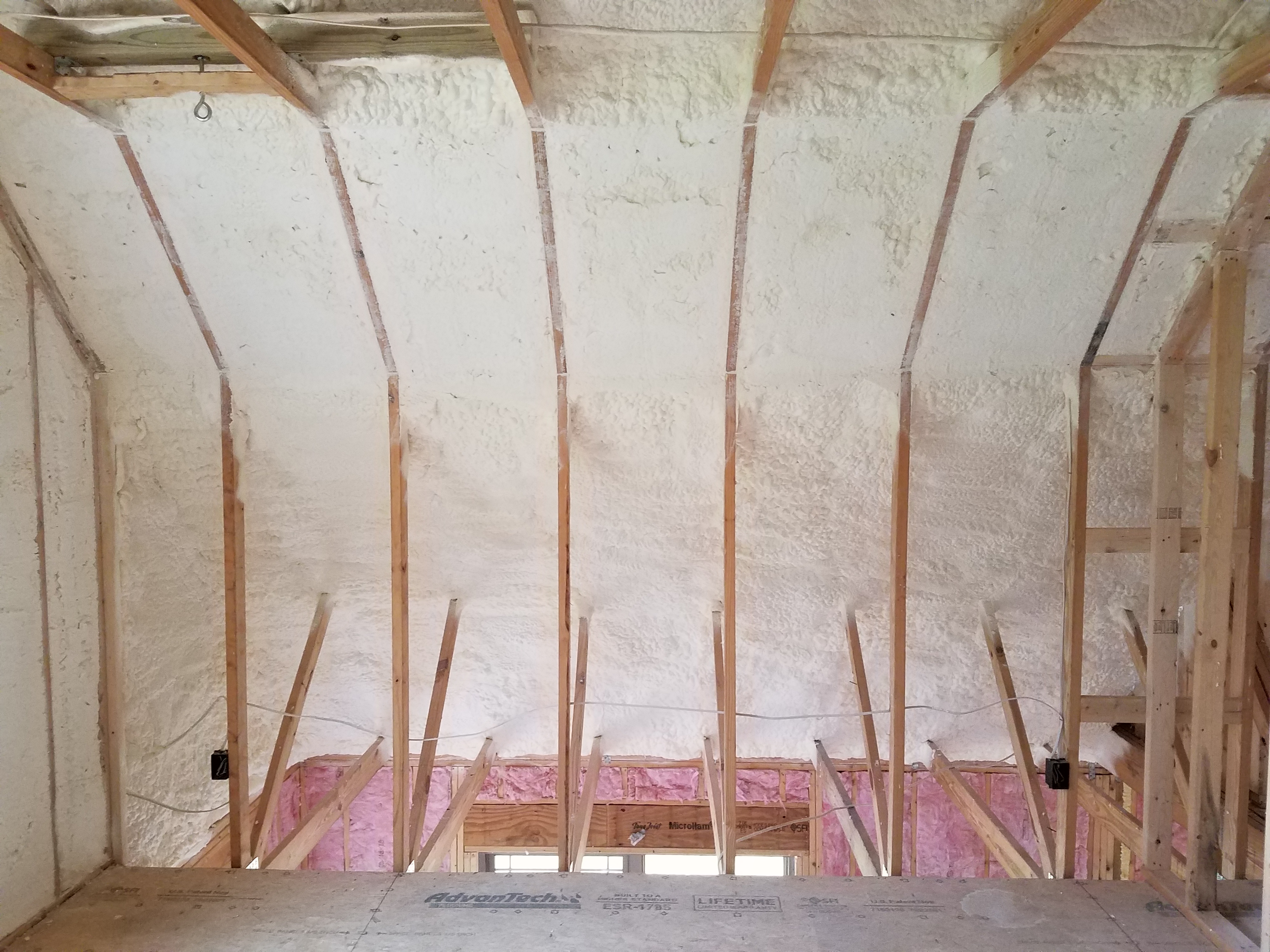
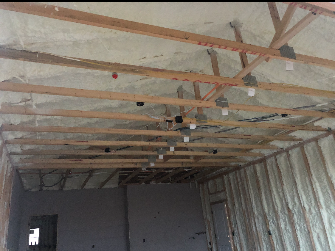
Right – Spray foam fills the roof joist cavities of this vaulted, unvented attic.
Image
Image
Right – Spray foam insulates the walls and ceilings separating the garage from the home.
Image
Right – Spray foam insulation fills the header above the door and fills the rim joist between floors.
Image
Right – Spray foam insulation is sprayed on the underside of the roof deck to provide a conditioned space in this low attic for the HVAC ducts.
Image
Right – Spray foam insulation was sprayed onto the ground and along the sides of the foundation walls and piers of this insulated crawl space.
Image
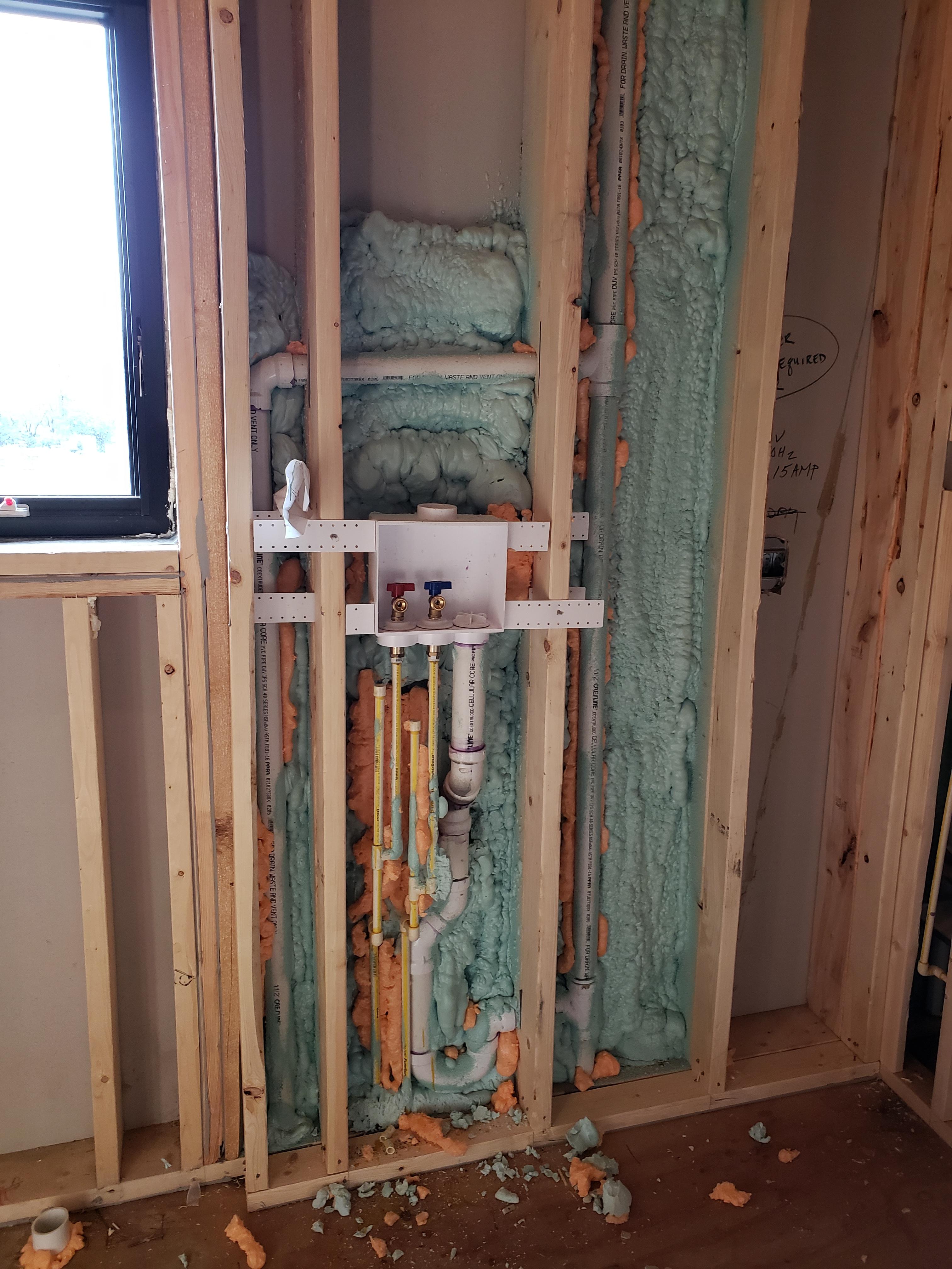
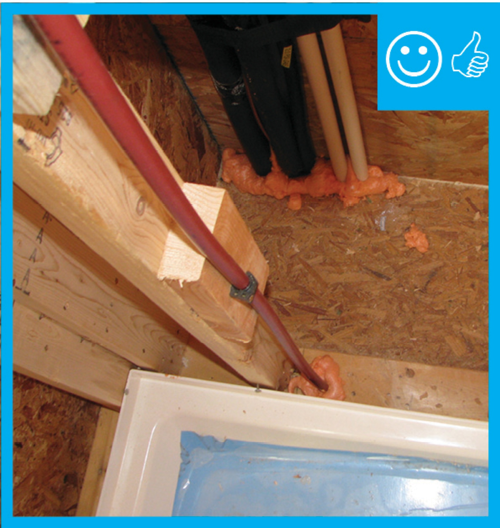
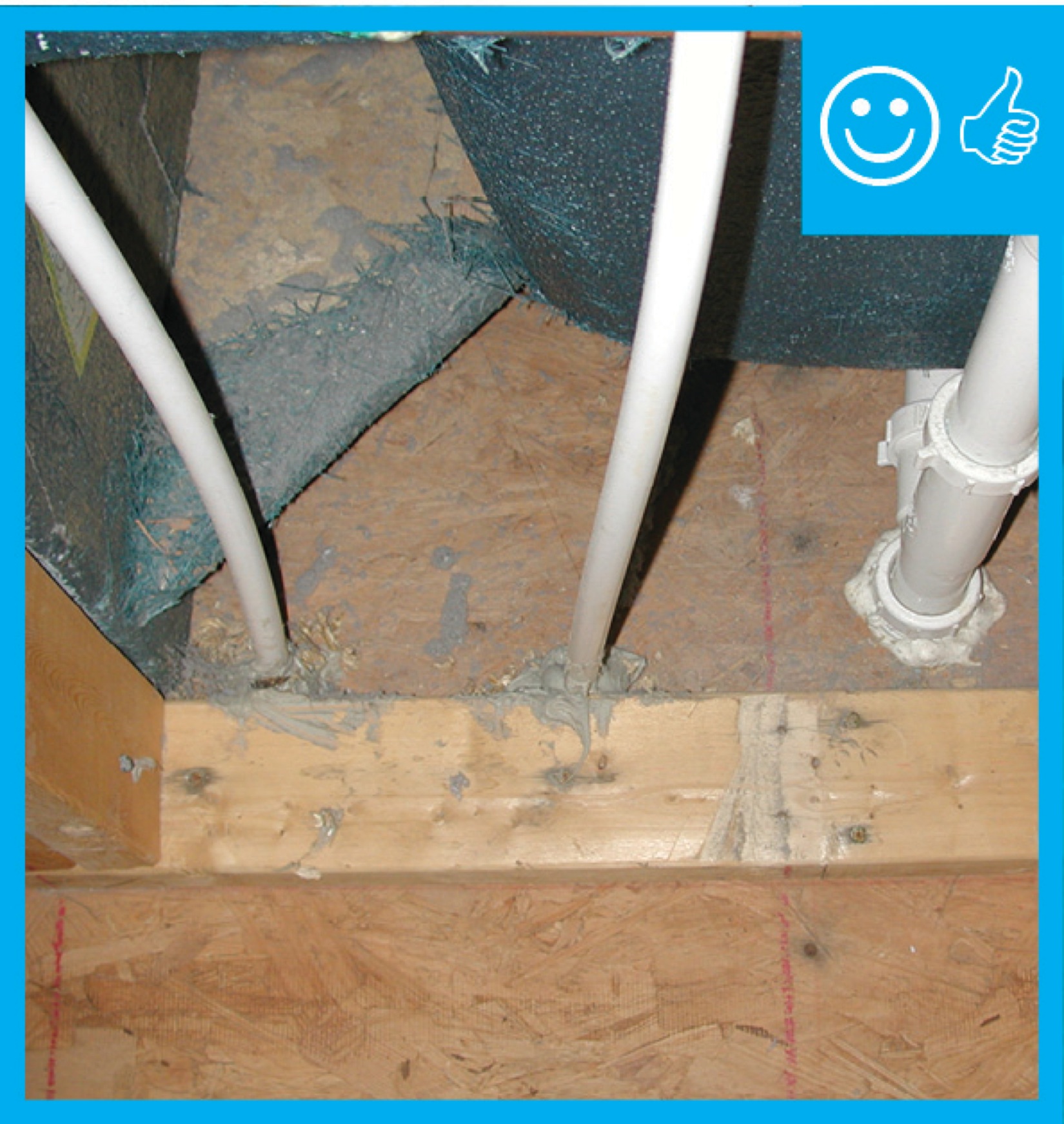
Right – Spray foam is used to carefully seal behind plumbing that was installed in an exterior wall.
Image
Image
Right – Spray foam was installed at the sheathing intersection as well as the sill plate to sub-floor connection.
Image

Right – Staggered 2x4s are placed every 12 inches on 2x6 plates, providing a nailing surface on each side of the wall every 24 inches.
Image
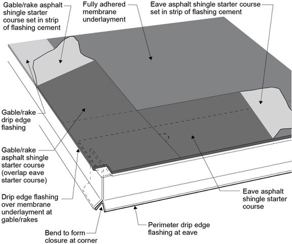
Right – Start asphalt shingle installation with a starter strip set in an 8-inch strip of flashing cement
Image
Right – Strategically placed trees provide shade to the south-facing windows of this building.
Image
Image

Image
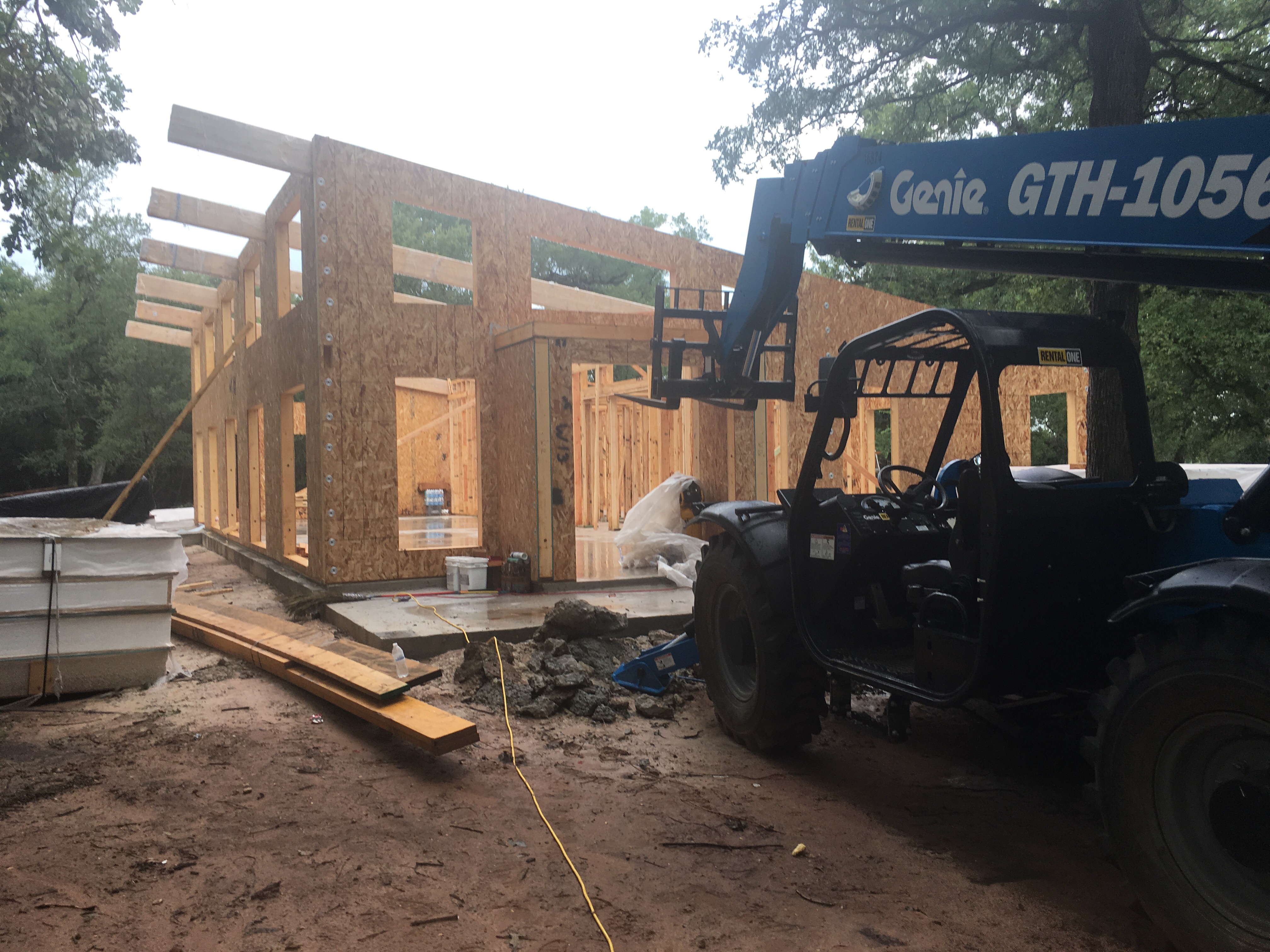
Right – Structural insulated panels are quickly assembled on site for this SIP house.
Image
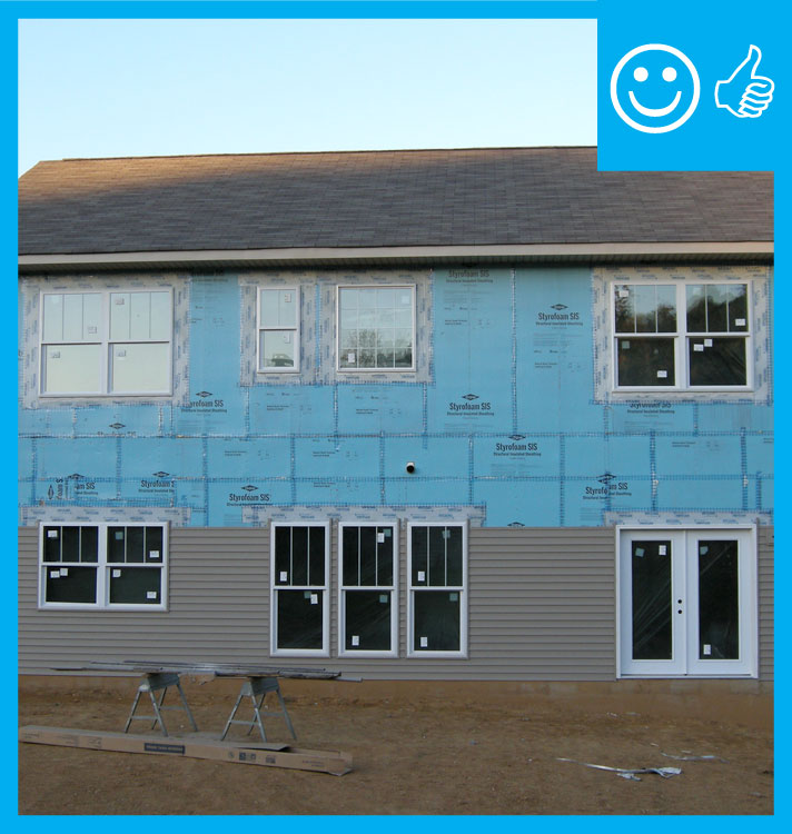
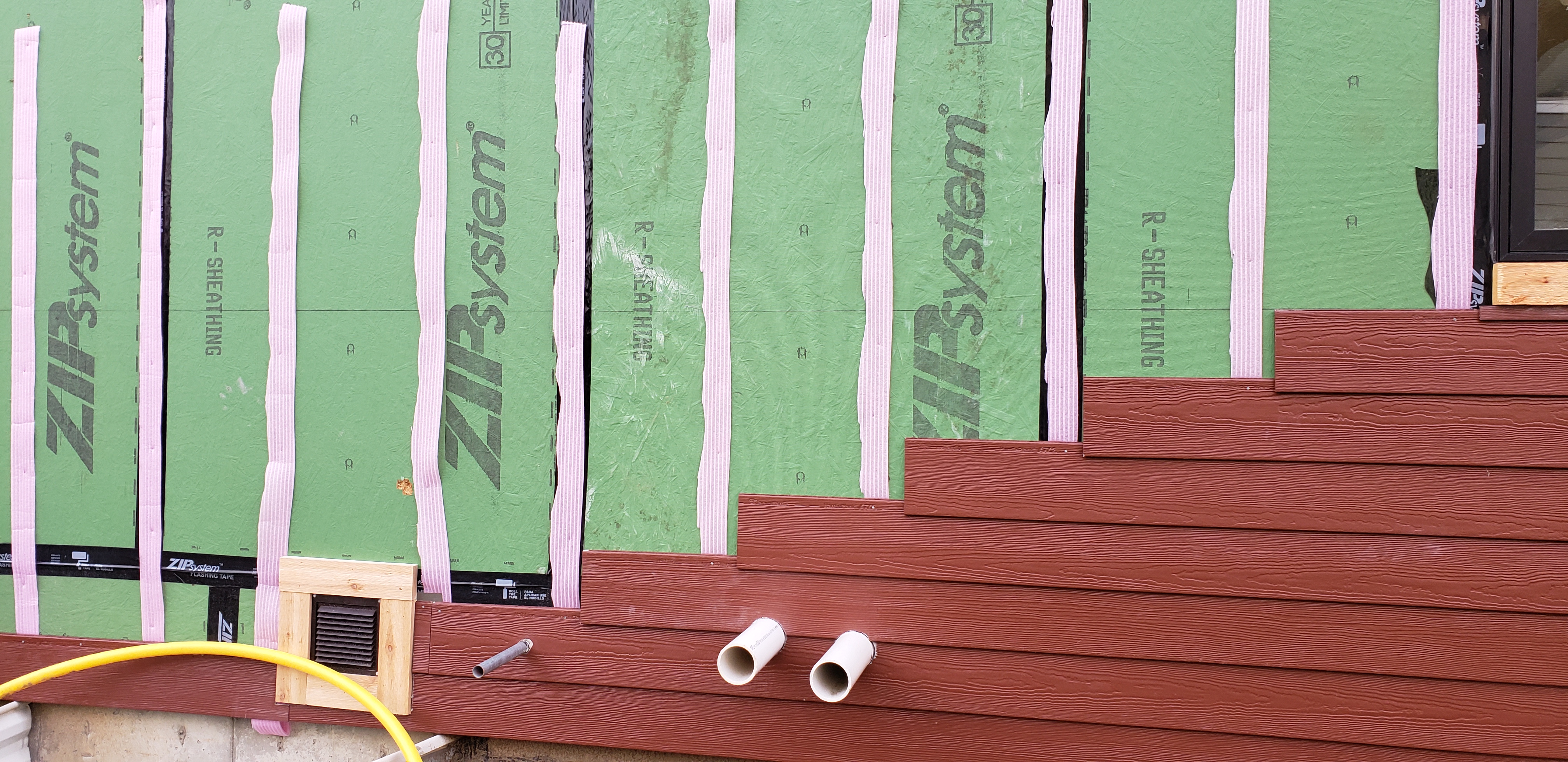
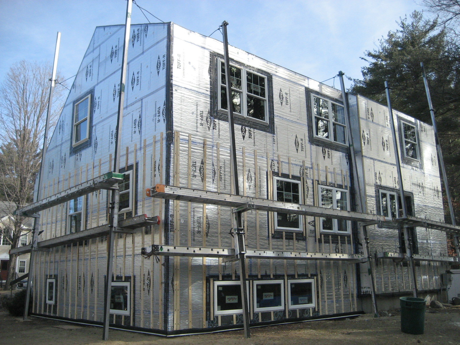
Right – Structural insulated sheathing can provide racking strength (lateral load resistance), and serve as an air barrier and thermal barrier if installed according to manufacturer’s specifications with taped, sealed seams
Image
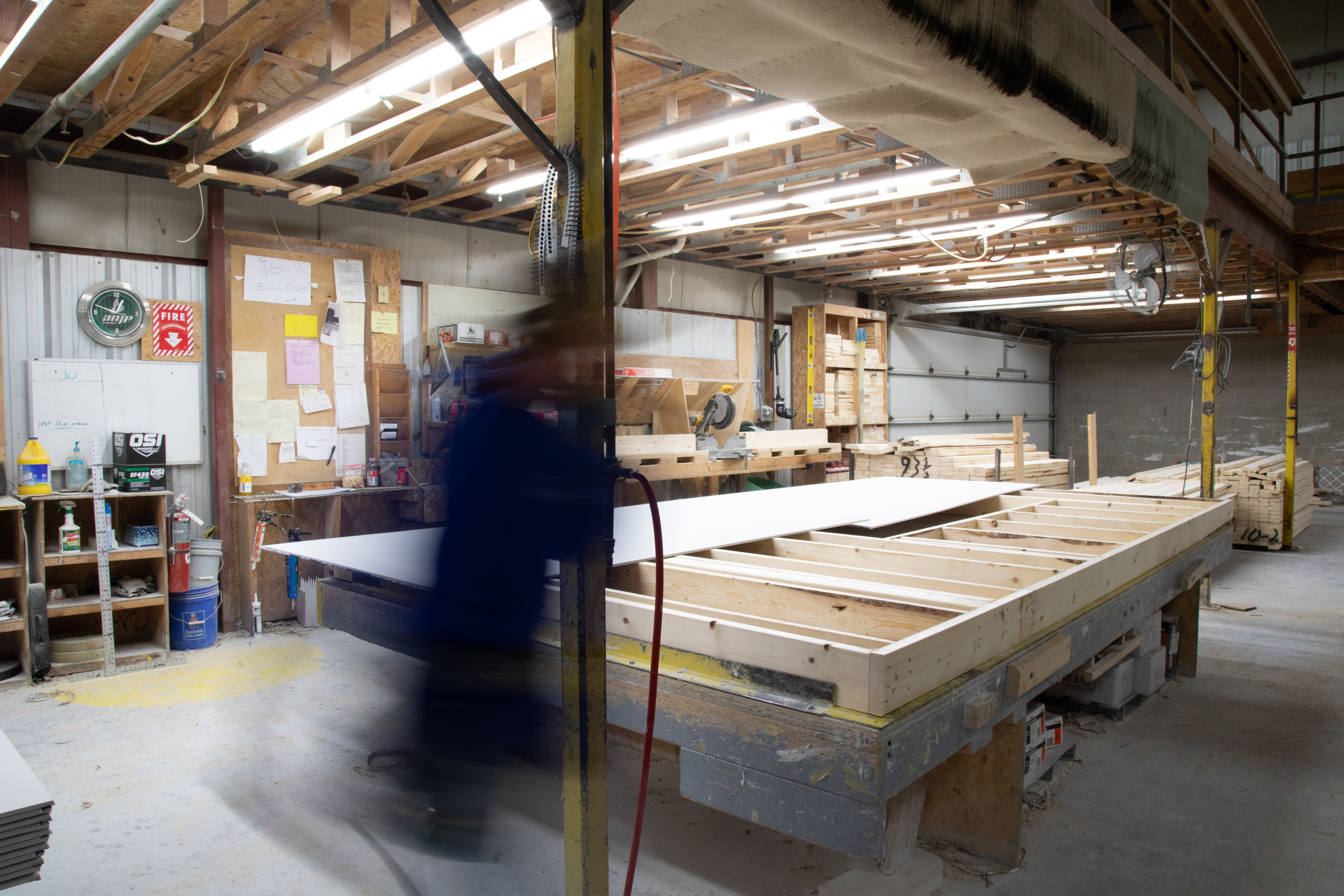
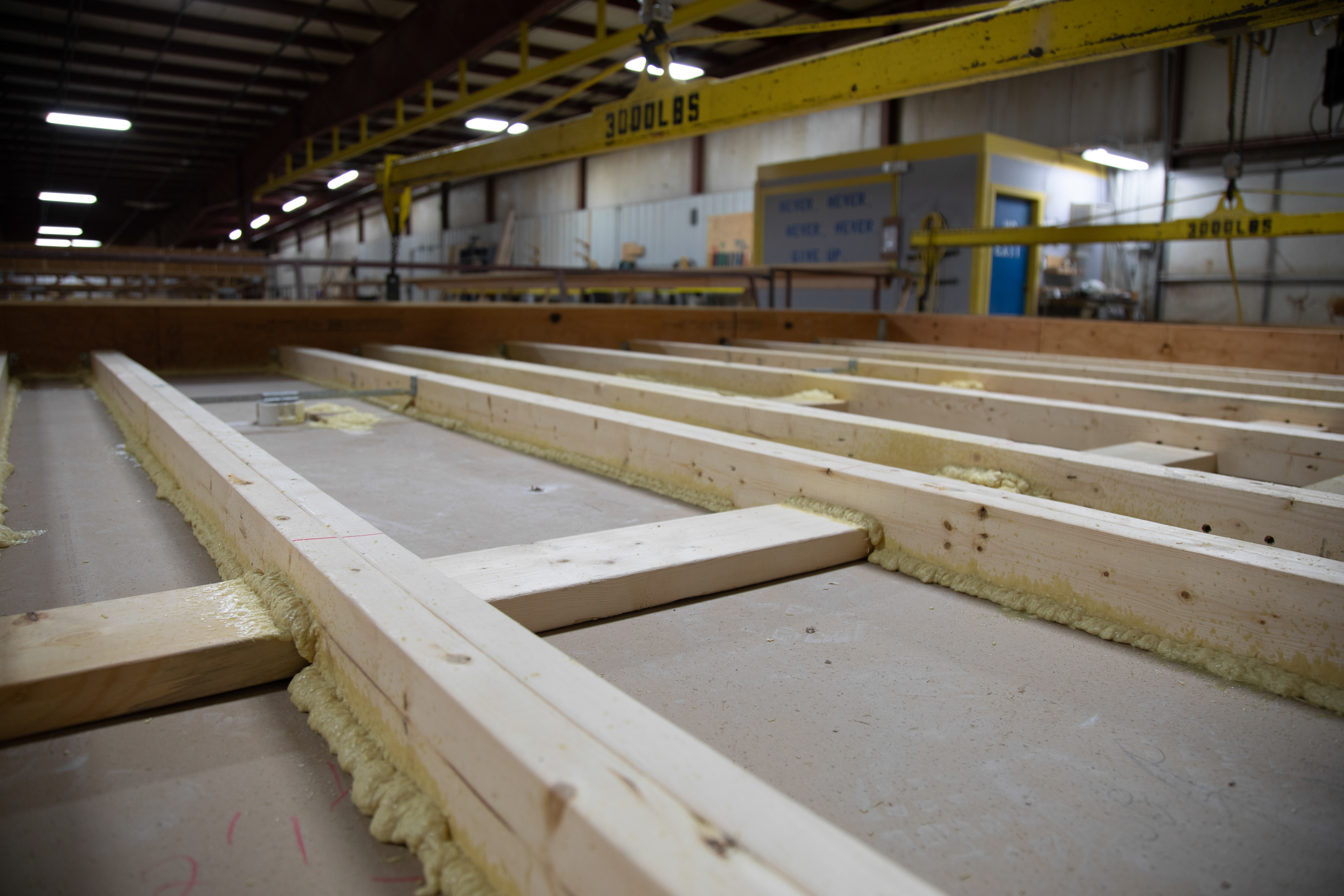
Right – Subfloors are installed in a clean, dry, well-lit factory setting for these modular, factory-built homes.
Image

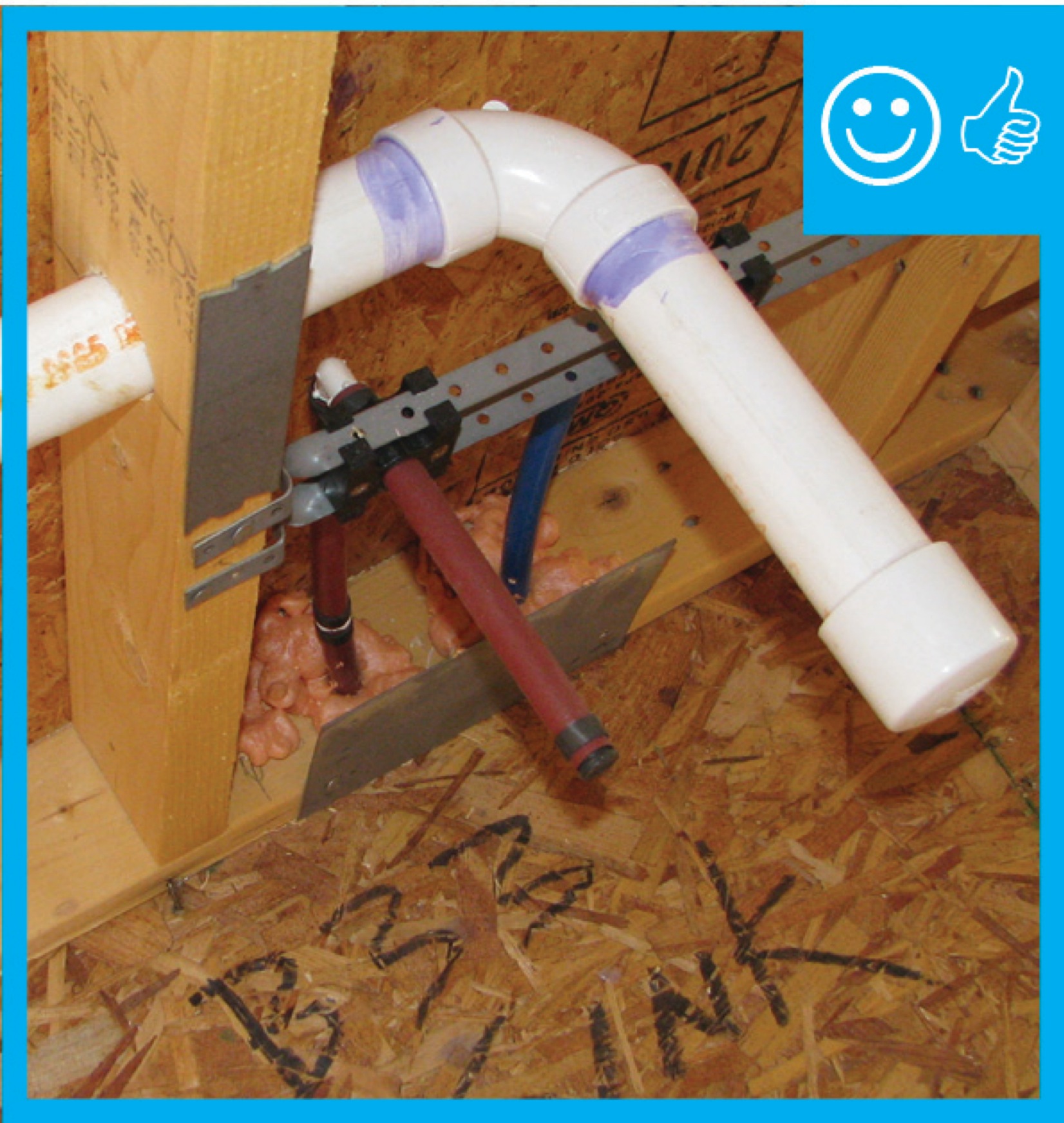
Right – Tape and spray foam are used to air seal around pipes that extend through exterior walls.
Image
Image
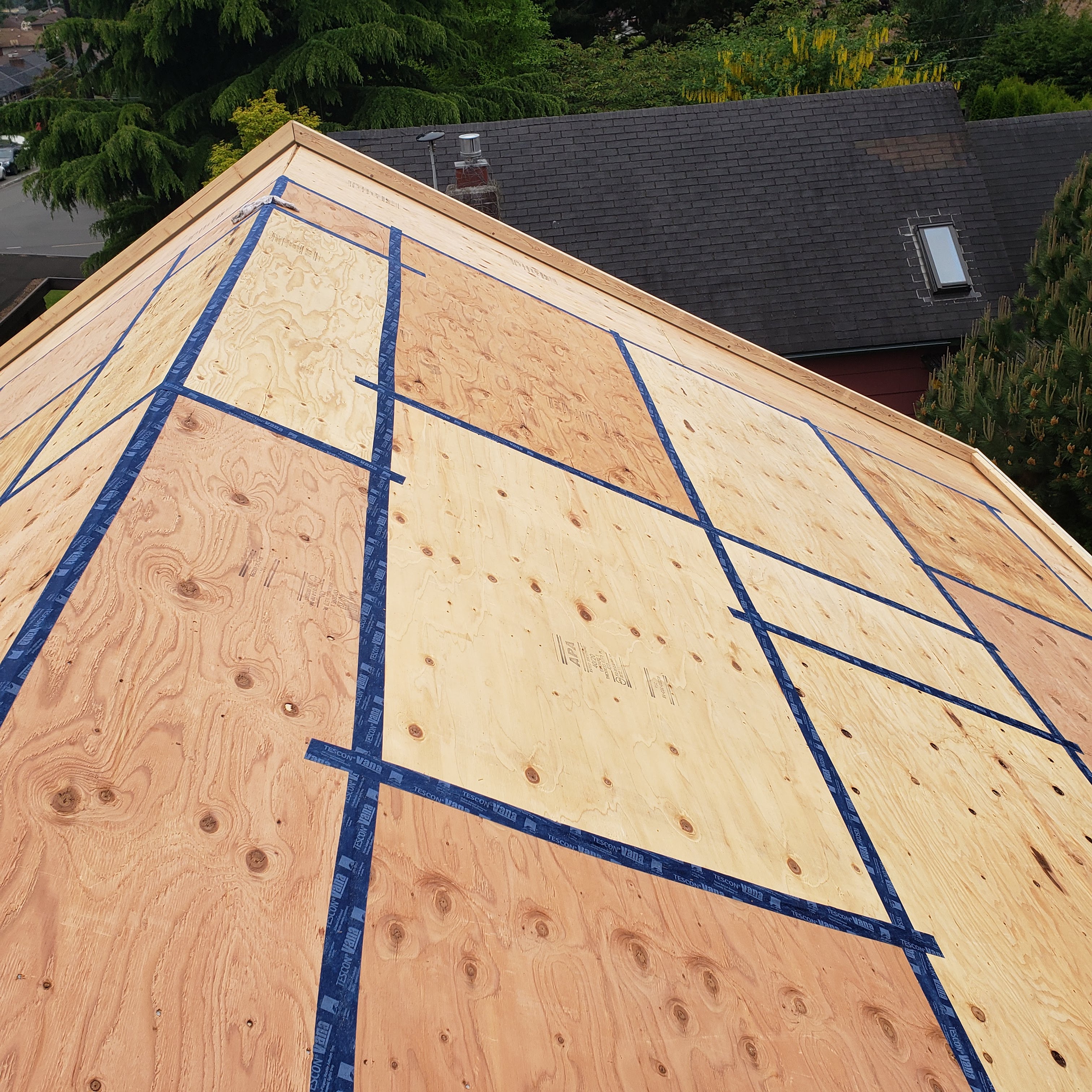
Right – Taping the roof sheathing seams can greatly decrease the likelihood of water infiltration into a home in the event of a hurricane.
Image

Right – Terra cotta tiles are attached to horizontal metal furring strips as the exterior cladding over mineral wool insulation on this multi-family building in Colorado.
Image
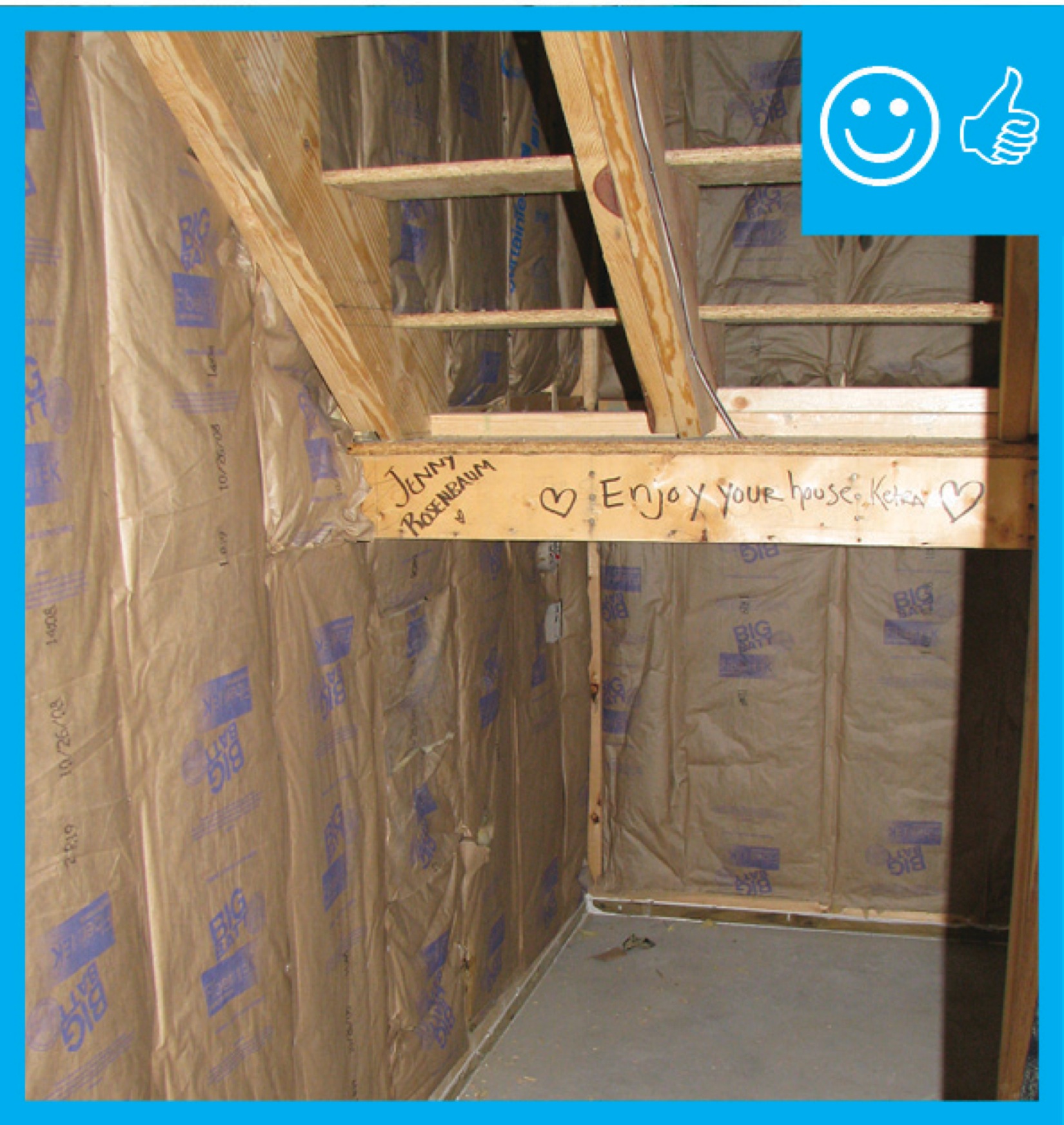
Right – the 2x6 walls are insulated with a flash-and-batt approach that includes spraying the wall cavities with one inch of open-cell foam to seal the sheathing to the framing then filling the wall cavities with R-19 fiberglass batts that are compressed
Image
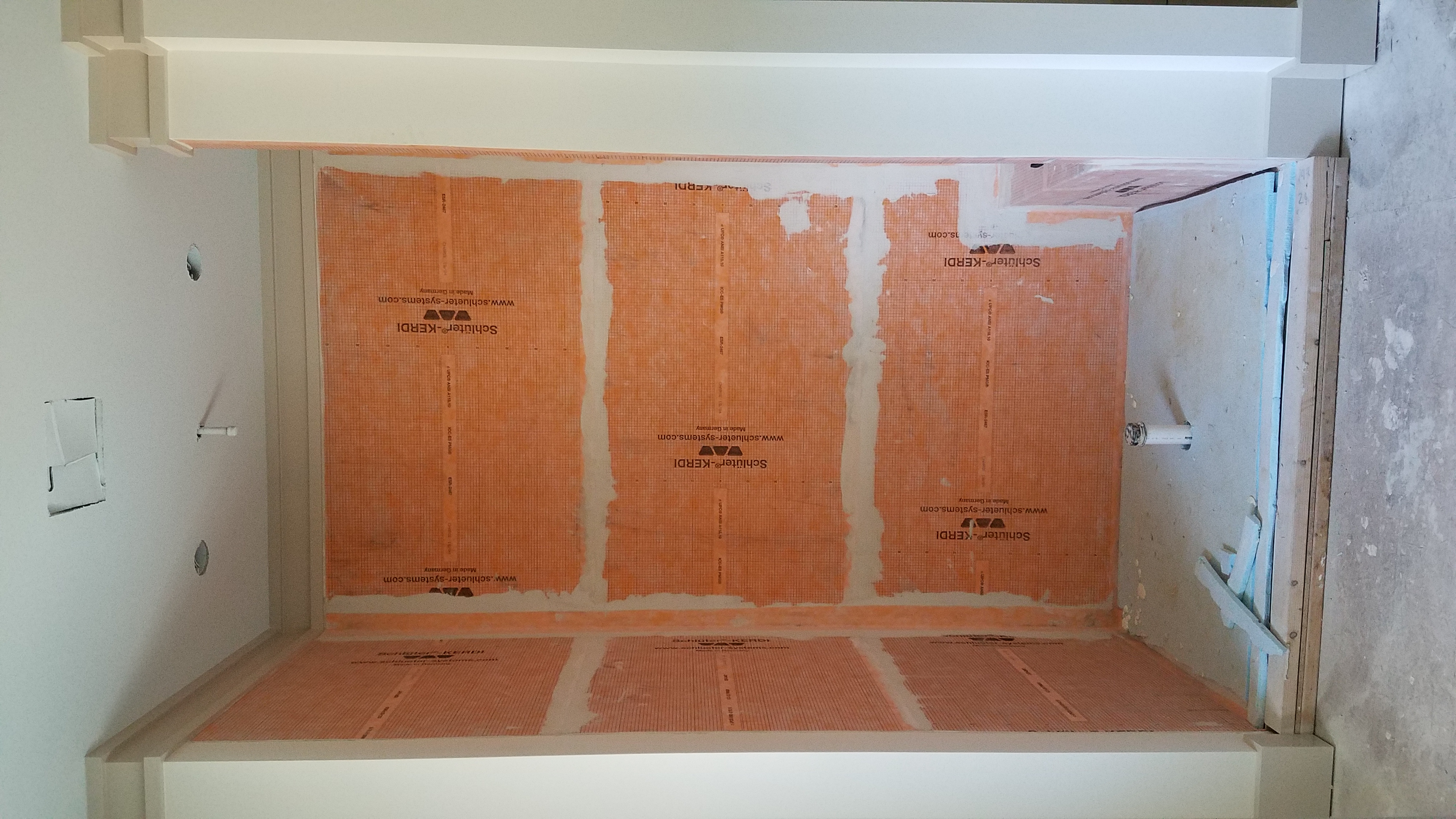
Right – The air- and water-barrier material lining the shower stall is mastic sealed to prevent leakage and rigid foam insulation is installed on the floor of the shower.
Image
Image
Image
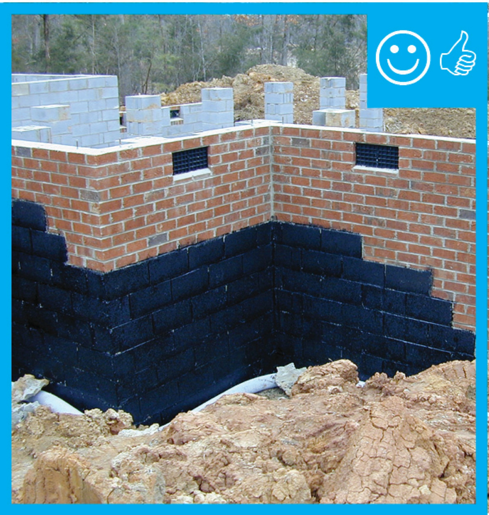
Right – The base of the wall is water proofed and the seam between the base of the wall and the sidewalk is air sealed.
Image
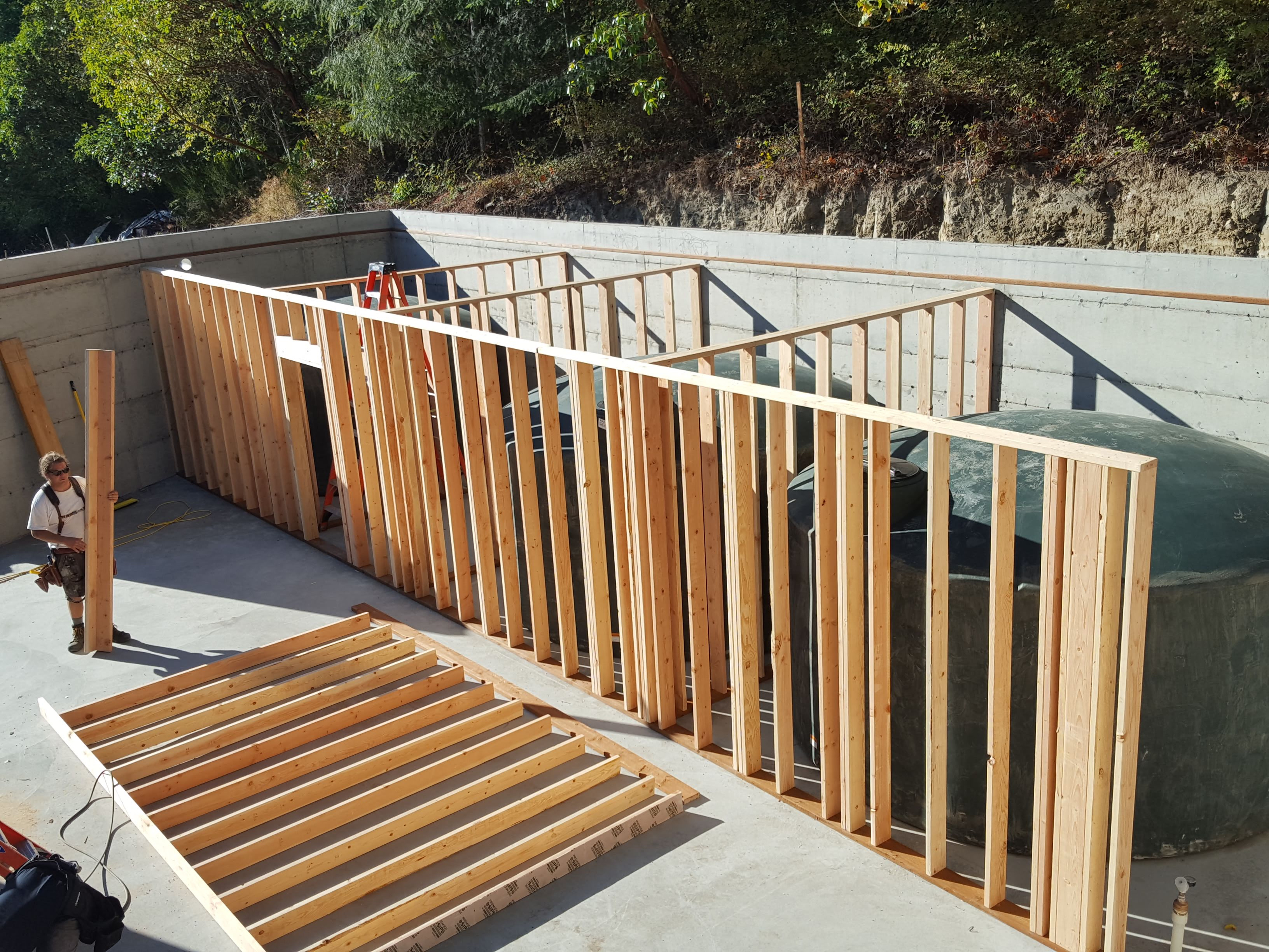
Right – The basement contains four 5,000-gallon rainwater holding tanks for this home which meets all of its water needs with rainwater.
Image
Right – The basement of this cold-climate home is insulated along interior walls with 2 inches of foil-faced rigid foam; finished basement walls also have a 2x4 interior wall insulated with R-19 blown-in fiberglass insulation and a poly vapor barrier.
Image
Image
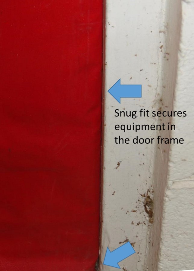
Right – The blower door is installed snugly and securely to the door frame during testing
Image
Right – The blower door pressure reference hose is placed well away from the outdoor side of the fan
Image
Right – The builder constructed a mock up of the wall assembly for this multi-family building.
Image
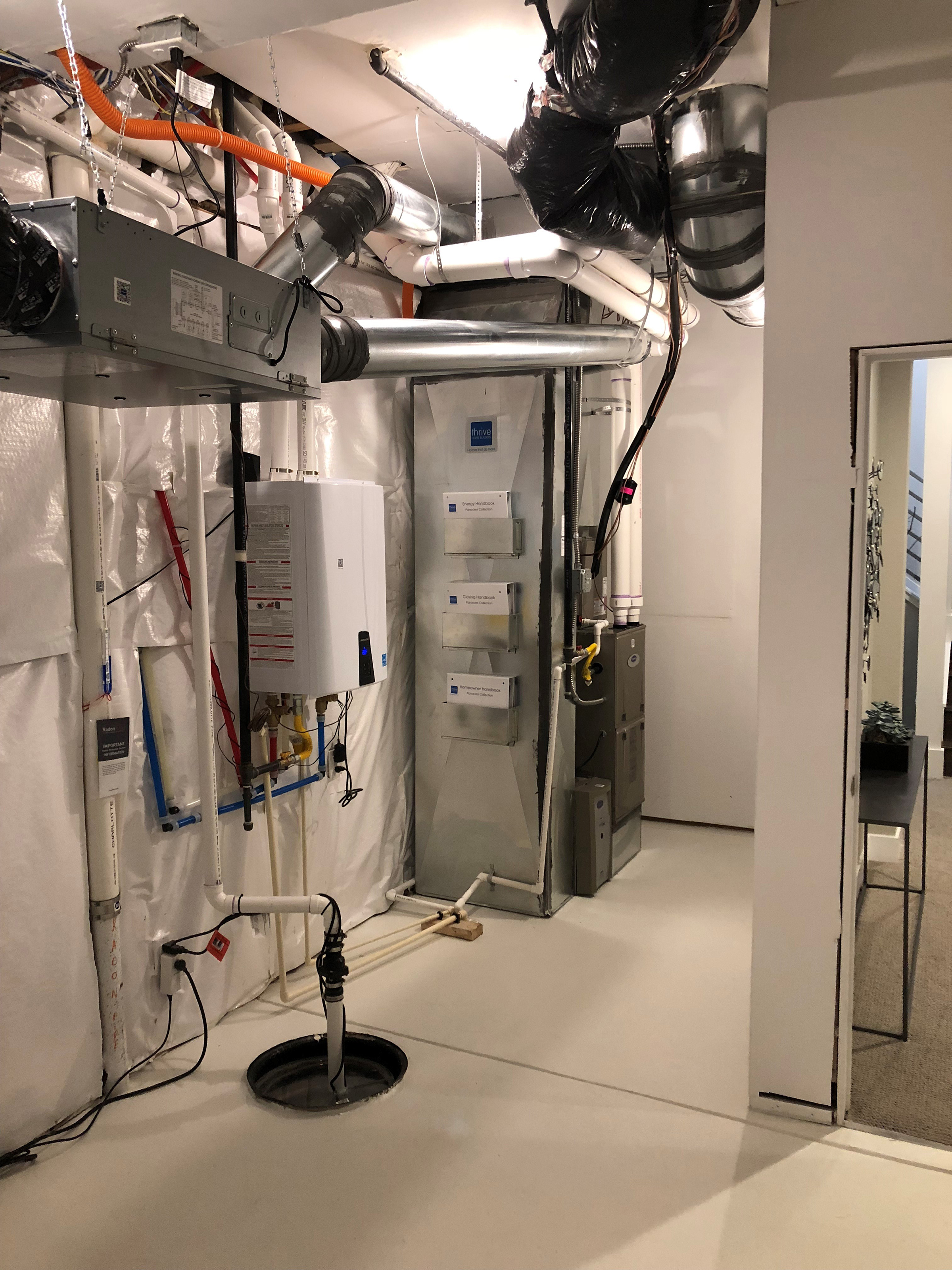
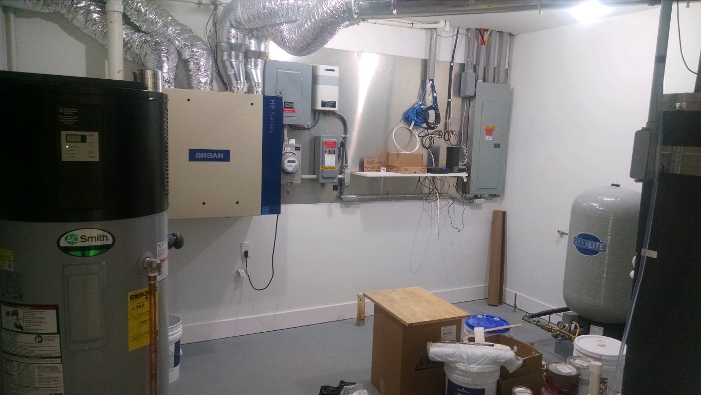
Right – The builder has provided homeowners manuals and racks to hold them on the side of the HVAC cabinet in the utility room.
Image
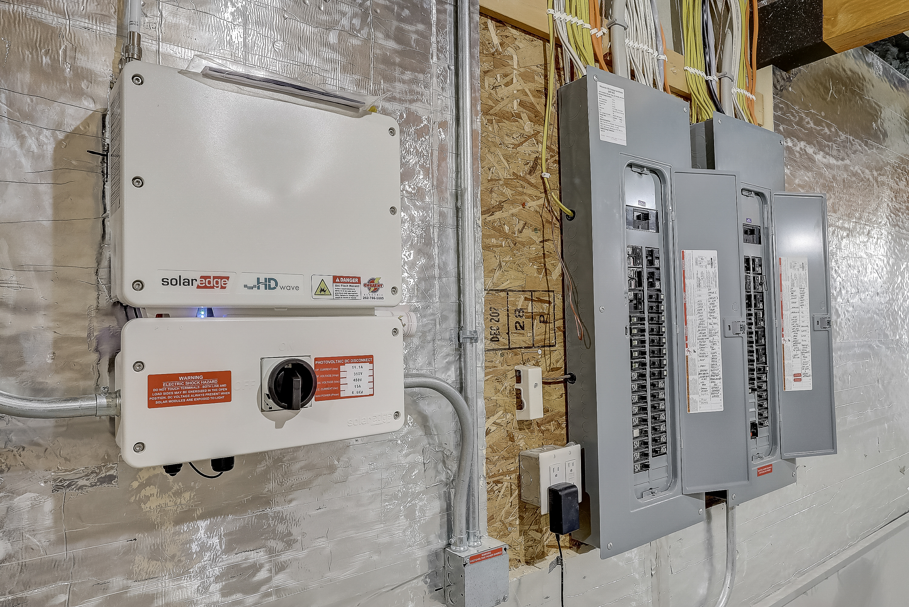
Right – The builder provided adequate wall space for the solar inverter next to the home’s electric panels.
Image
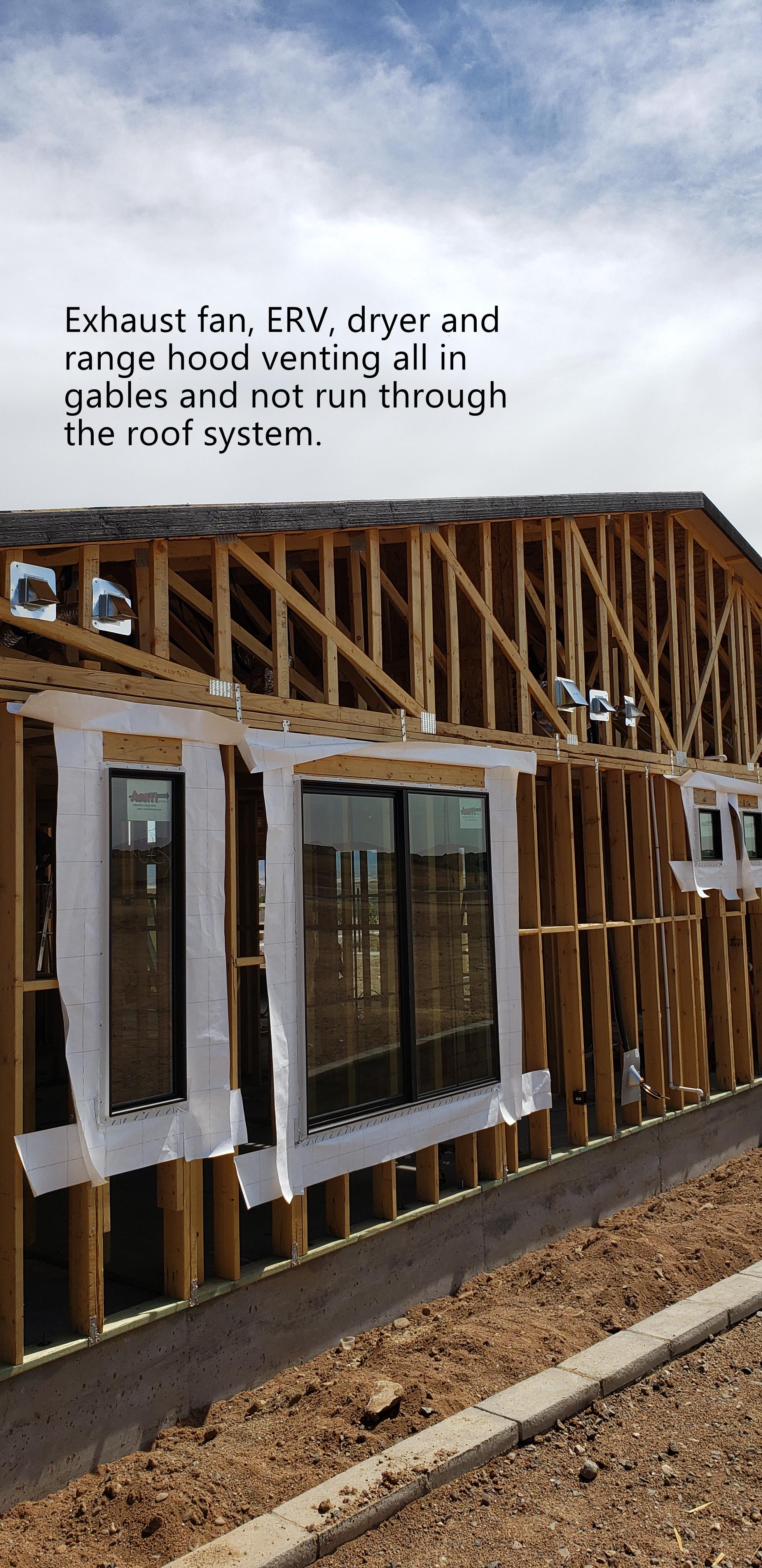
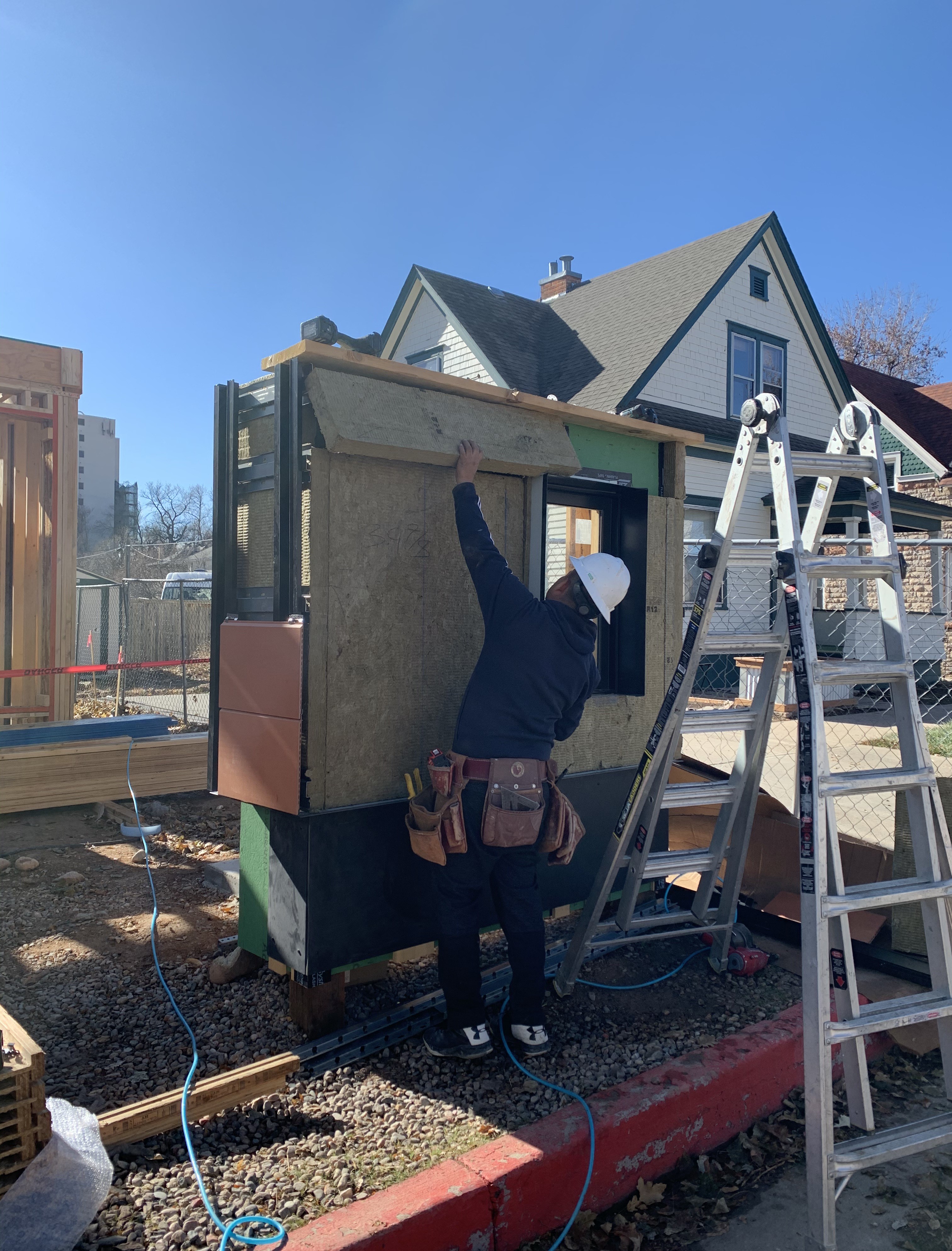
Right – The builder routed all vents through side walls to avoid holes in the roof.
Image
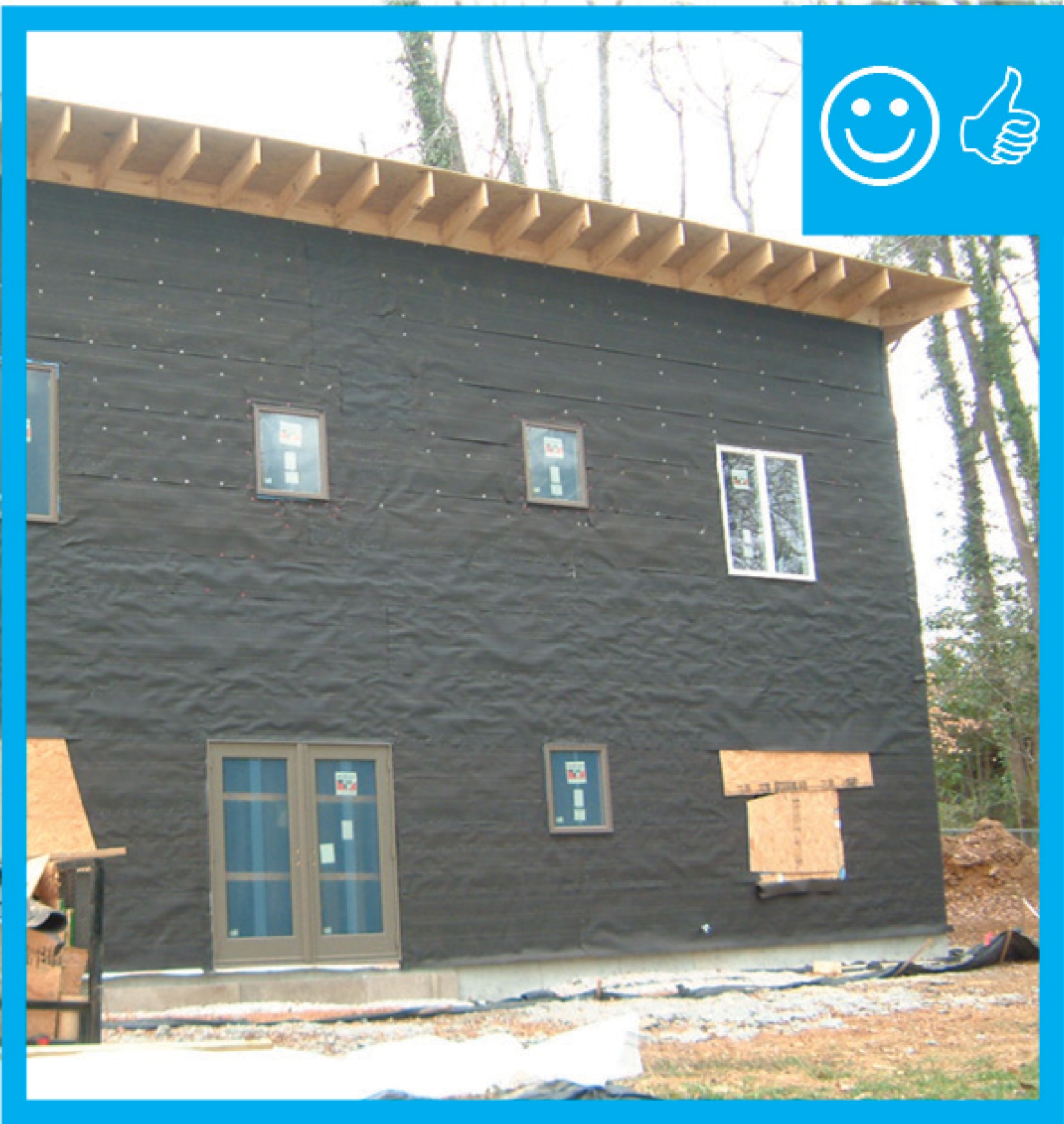
Right – The building felt is installed on all exterior walls and provides a complete drainage system
Image
Right – the building on the right employs light-colored walls, deep tinting, and deeply recessed windows to minimize solar heat gain
Image
Right – The canopy of this tree is high enough to allow views out the windows of this home while providing excellent shade to walls, windows, and roof.
Image
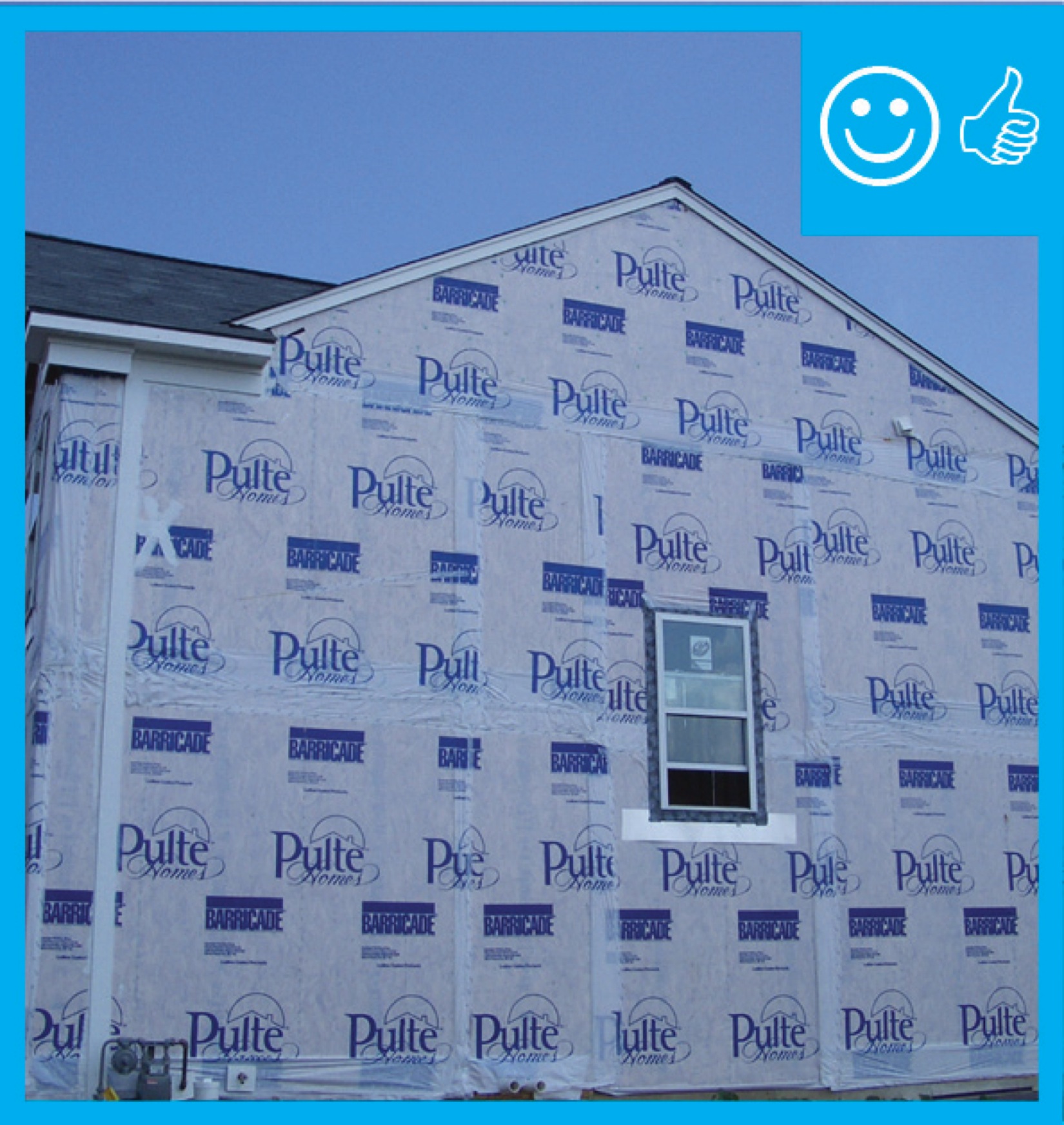
Right – The coated OSB sheathing can take the place of house wrap to serve as the weather-resistant barrier because it is sealed at the seams with a paint-on flashing.
Image
Right – The corridor in this multistory building is pressurized with outdoor supply air.
Image
Image

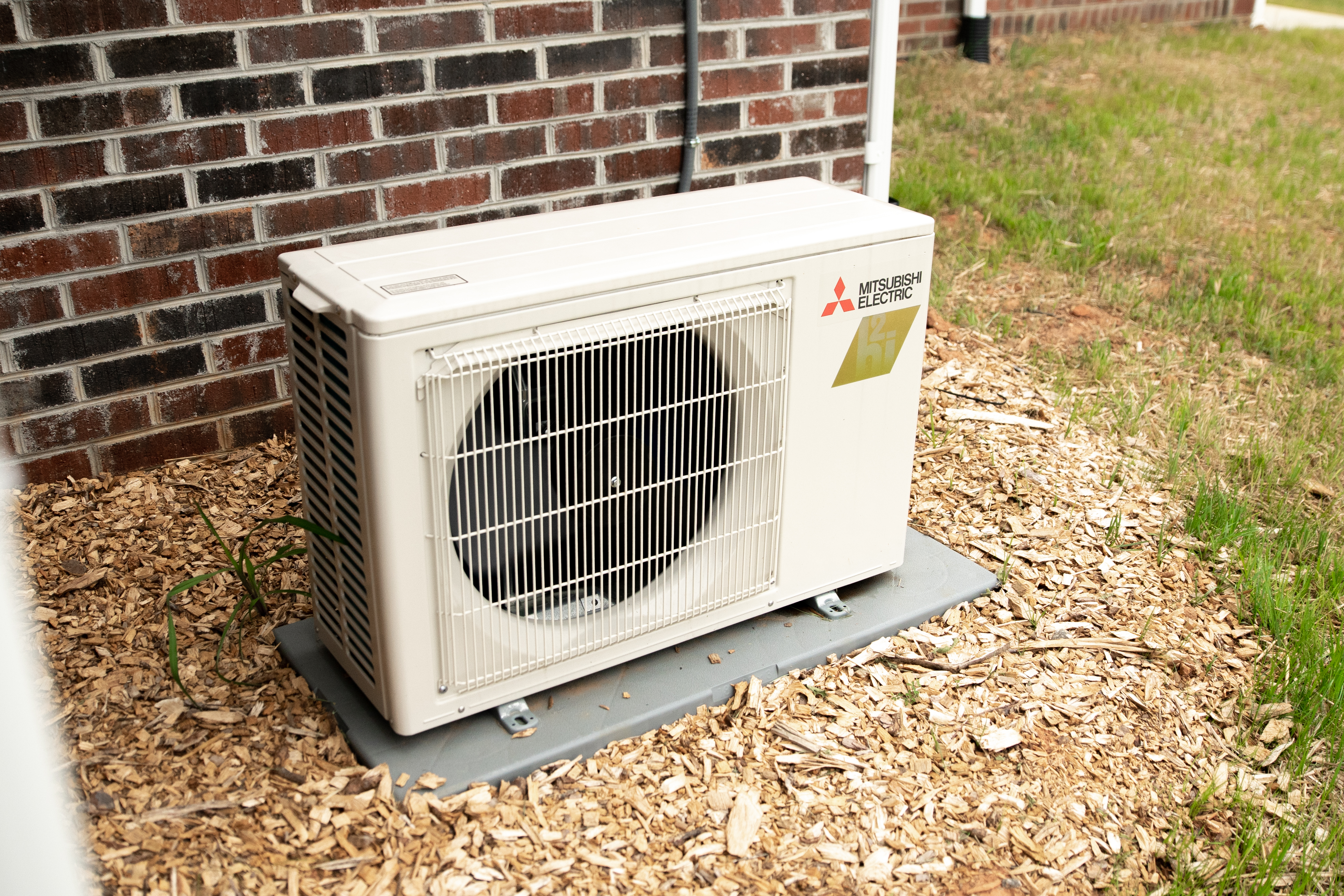
Right – The double compressor unit supplies multiple interior minisplit heat pump heads.
Image

Right – The double-pane windows have low-emissivity coatings on three surfaces to reduce heat transfer through the glass allowing in views but preventing heat loss in winter and heat gain in summer.
Image
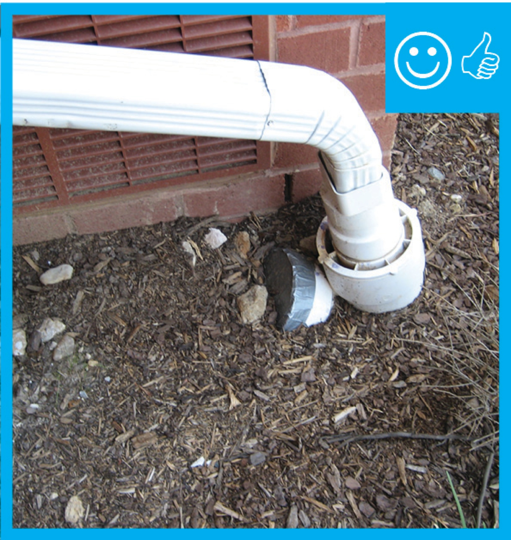
Right – The downspout pipe is far enough away from the foundation to prevent moisture problems
Image
Right – The downspout terminates into a catchment system that moves water away from the foundation of the house
Image

Right – The drain slopes away from the foundation and terminates at the proper distance
Image
Right – The drain tile connects to a sump pump which will pump water away from the foundation
Image
Right – The drain tile is installed along the bottom of the entire foundation footing
Image
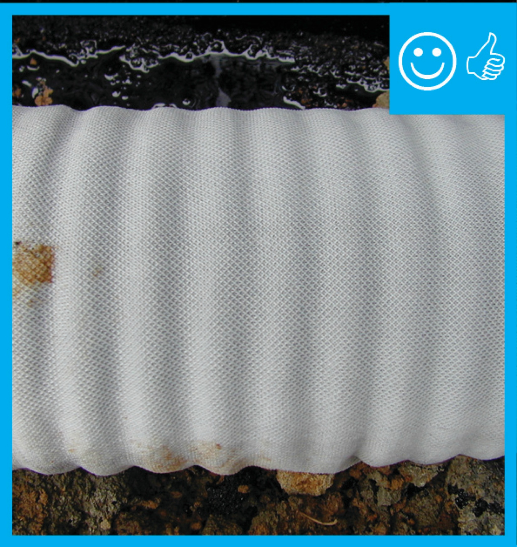
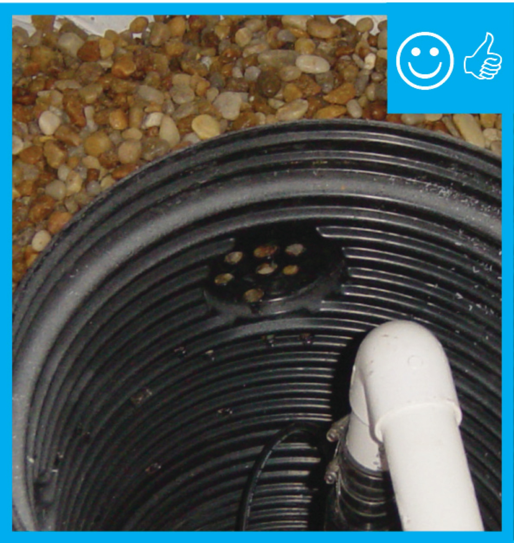
Right – The drain tile is wrapped in fabric which will prevent it clogging with debris
Image

Right – The ductless minisplit in this open area is installed in the ceiling rather than on a wall.
Image
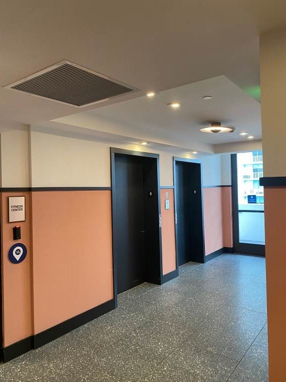
Right – The elevator lobby of this multistory building is pressurized with outdoor air supplied to the space through this ceiling supply register.
Image

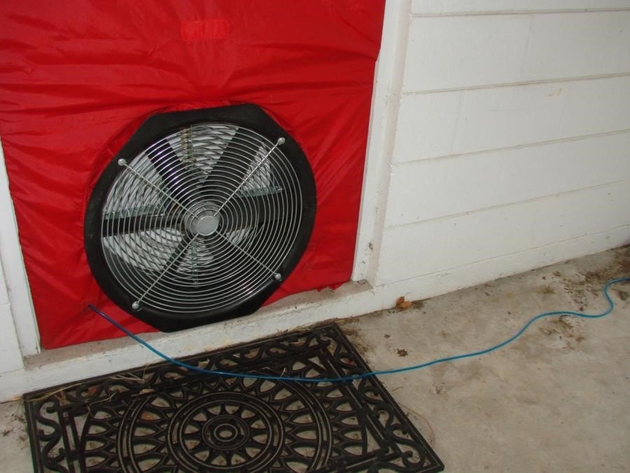
Right – The energy rater used a window to test whole-house air leakage with this blower door testing equipment.
Image
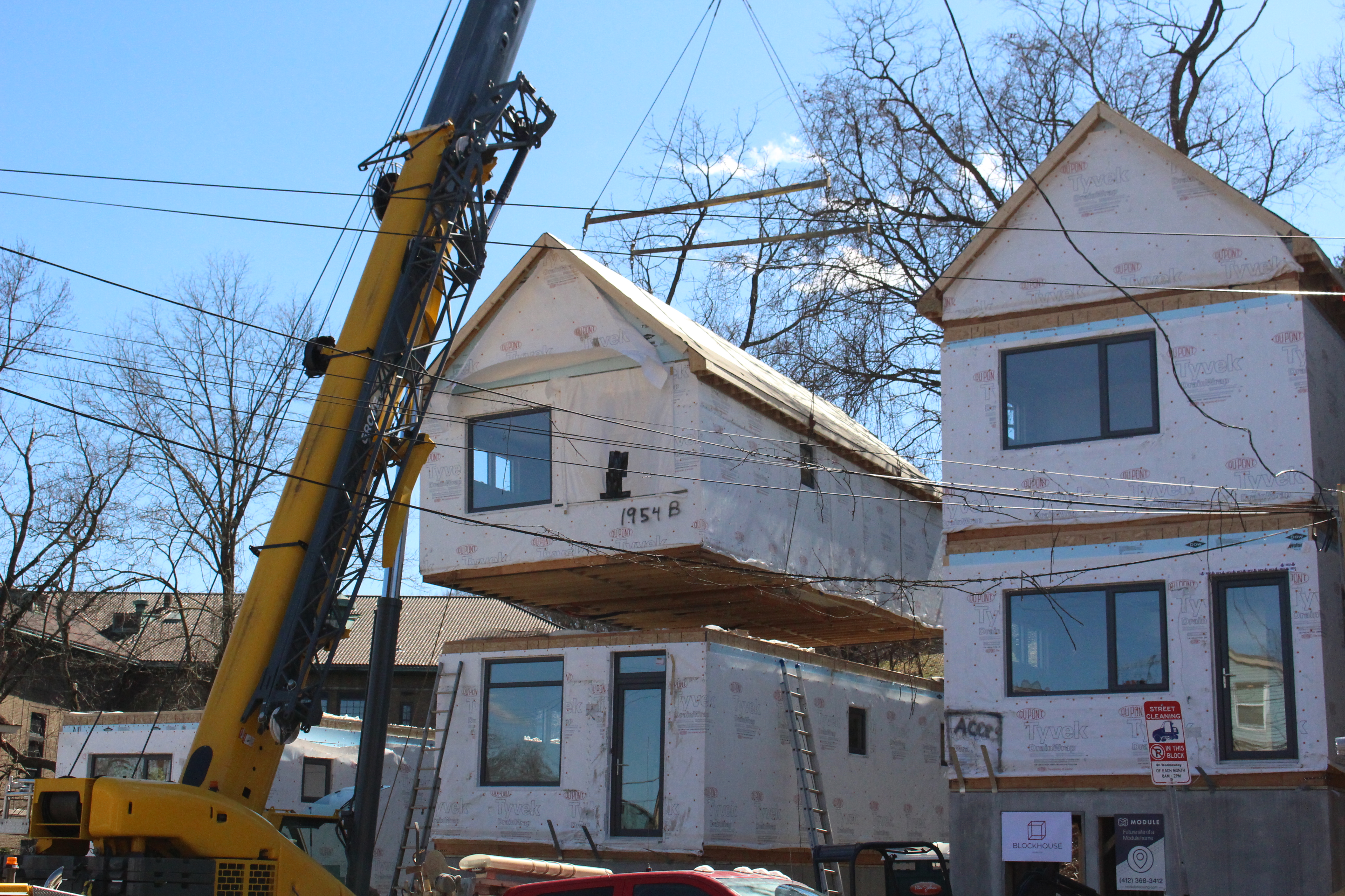
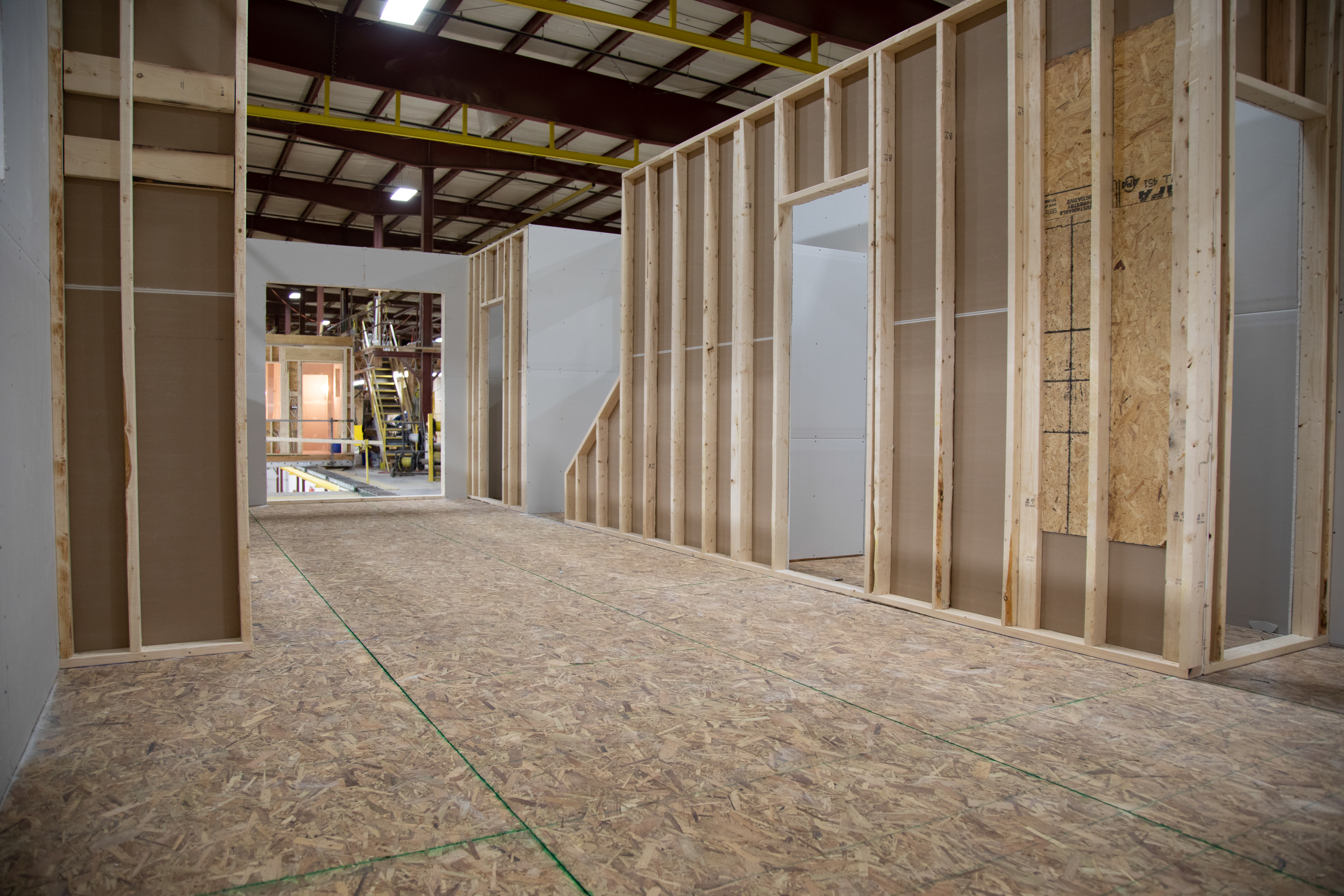
Right – The entire first floor and second floor of these modular homes were assembled in the factory and installed on an insulated concrete basement foundation on site.
Image
Right – The exhaust fan duct is sealed to the fan with mastic and the fan opening is covered with cardboard to keep out dust during construction.
Image
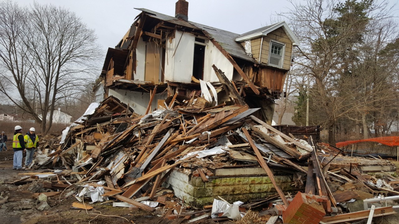
Right – The existing home on this site was in poor condition and was demolished to make room for a new highly efficient DOE Zero Energy Ready home.
Image

Right – The exterior unit of the mini-split heat pump is installed on blocks on a concrete pad to keep the equipment elevated above mud and water runoff.
Image
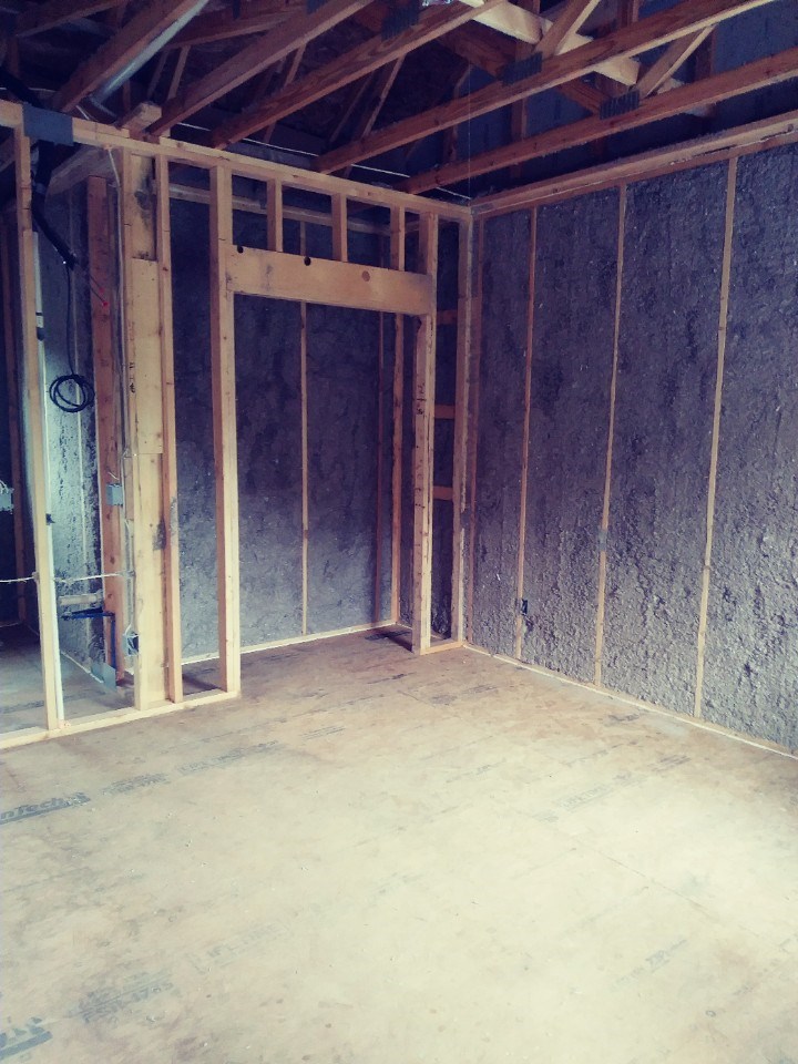
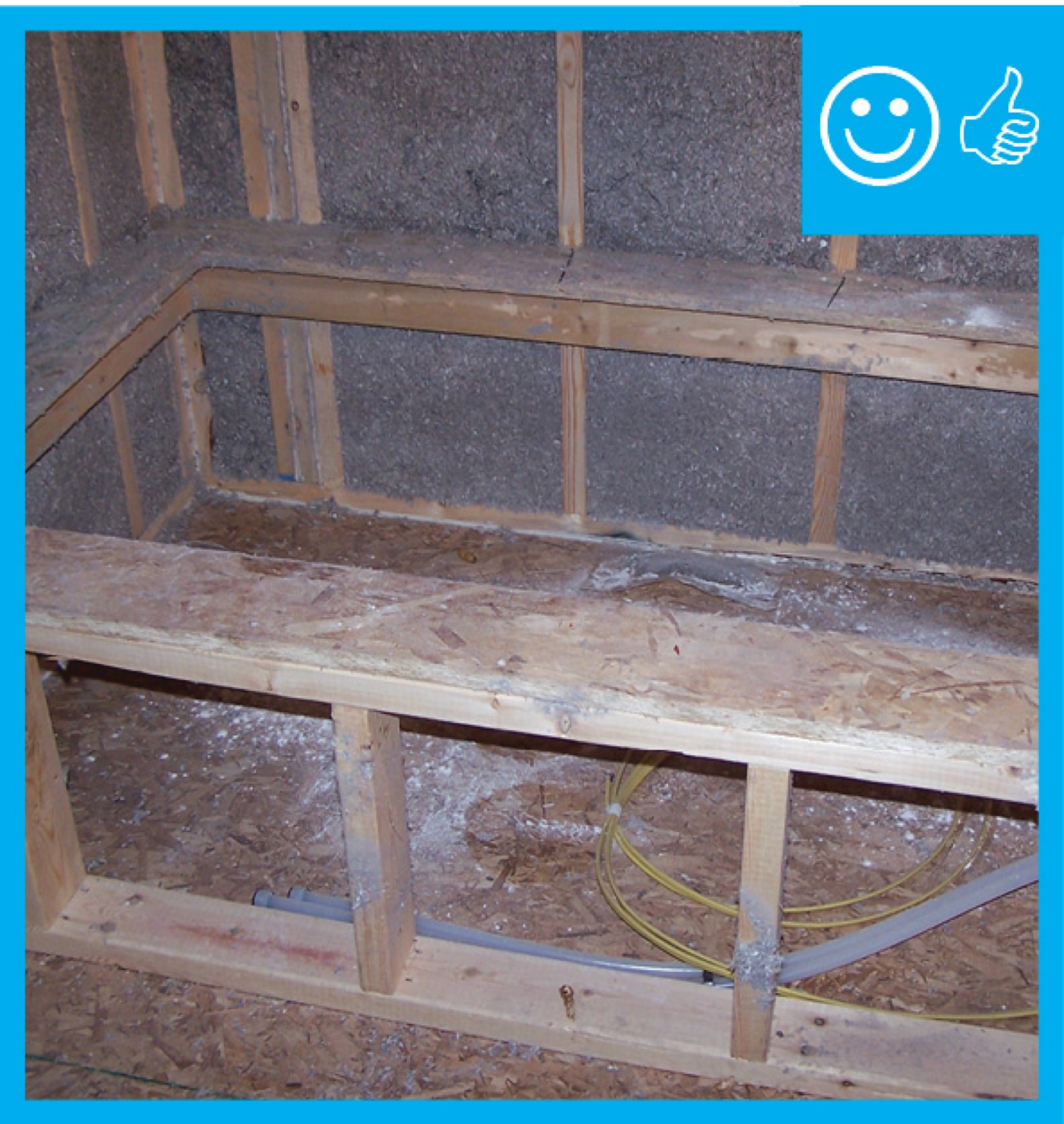
Right – The exterior wall cavities are completely filled with dense-packed cellulose.
Image

Image
Right – The flashing is properly installed to create a complete drainage system with continuous rigid insulation sheathing/siding
Image
Right – The floor and wall system on this open-foundation home use rigid foam rather than fibrous cavity insulation to reduce risk of water damage.
Image
Right – The foundation of this ICF home was constructed of ICFs that were set in place on a gravel bed, then 3.5 inches (R-36) of closed-cell spray foam was sprayed directly onto the gravel, providing an effective air, vapor, and thermal barrier.
Image
Right – The foundation wall consists of prefab concrete wall panels with integrated insulation.
Image
Image
Right – The framing around the window is thoroughly flashed with liquid flashing.
Image

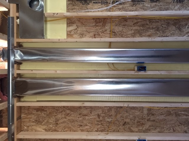
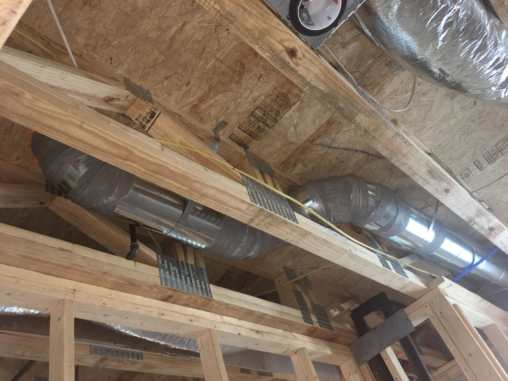
Right – The hard metal ducts are located in conditioned space between floor joists and all seams are sealed with approved metal tape.
Image

Right – The heat pump water heater is equipped with a recirculating pump to push hot water to distant fixtures.
Image

Right – The heavy roof underlayment was wrapped over the edges and down onto the walls, providing a continuous air barrier at this critical juncture; the second story will have narrow overhangs, matching the existing architecture style in the neighborhood
Image
Image
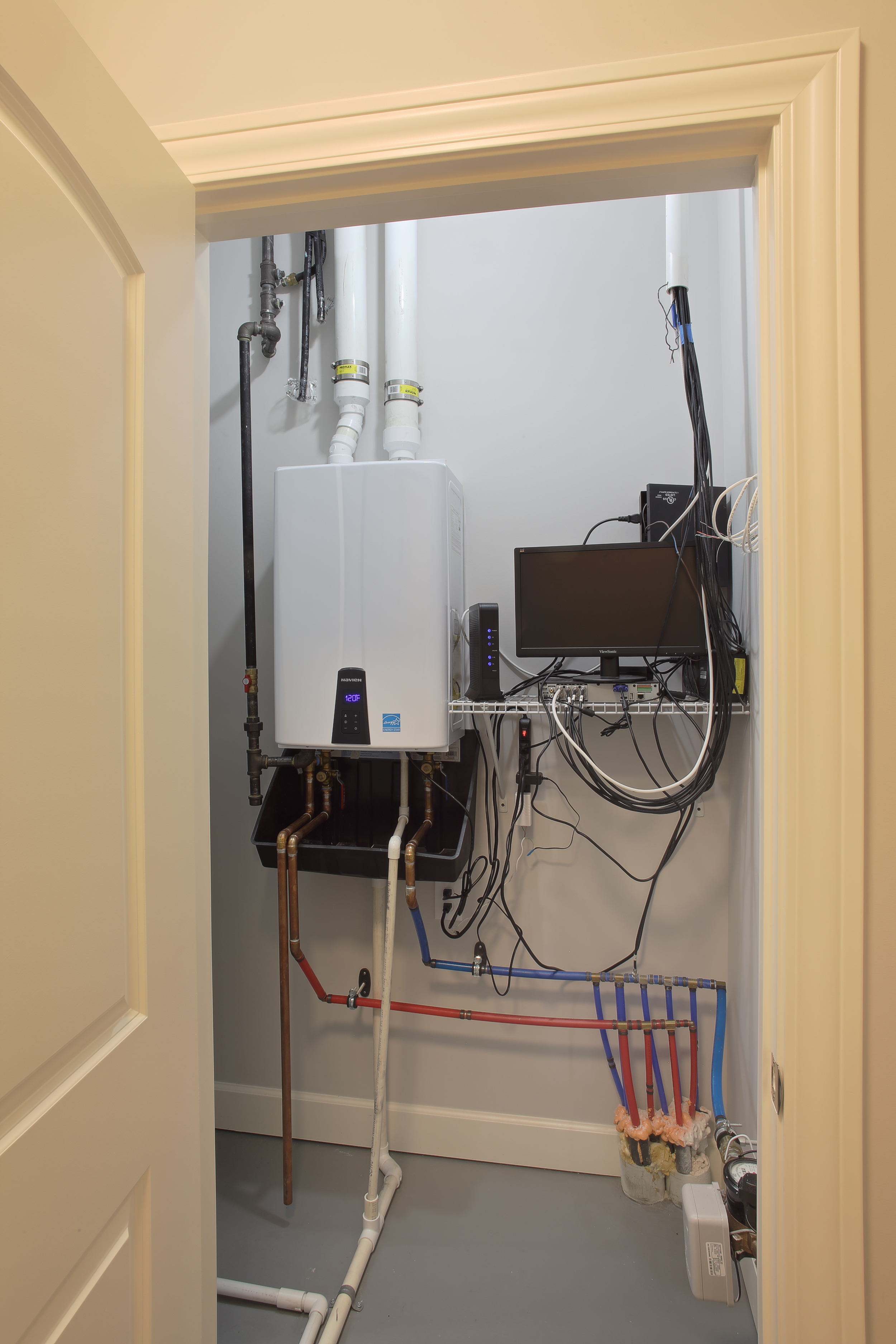
Right – The home’s energy management system is installed in a utility closet next to the tankless water heater.
Image
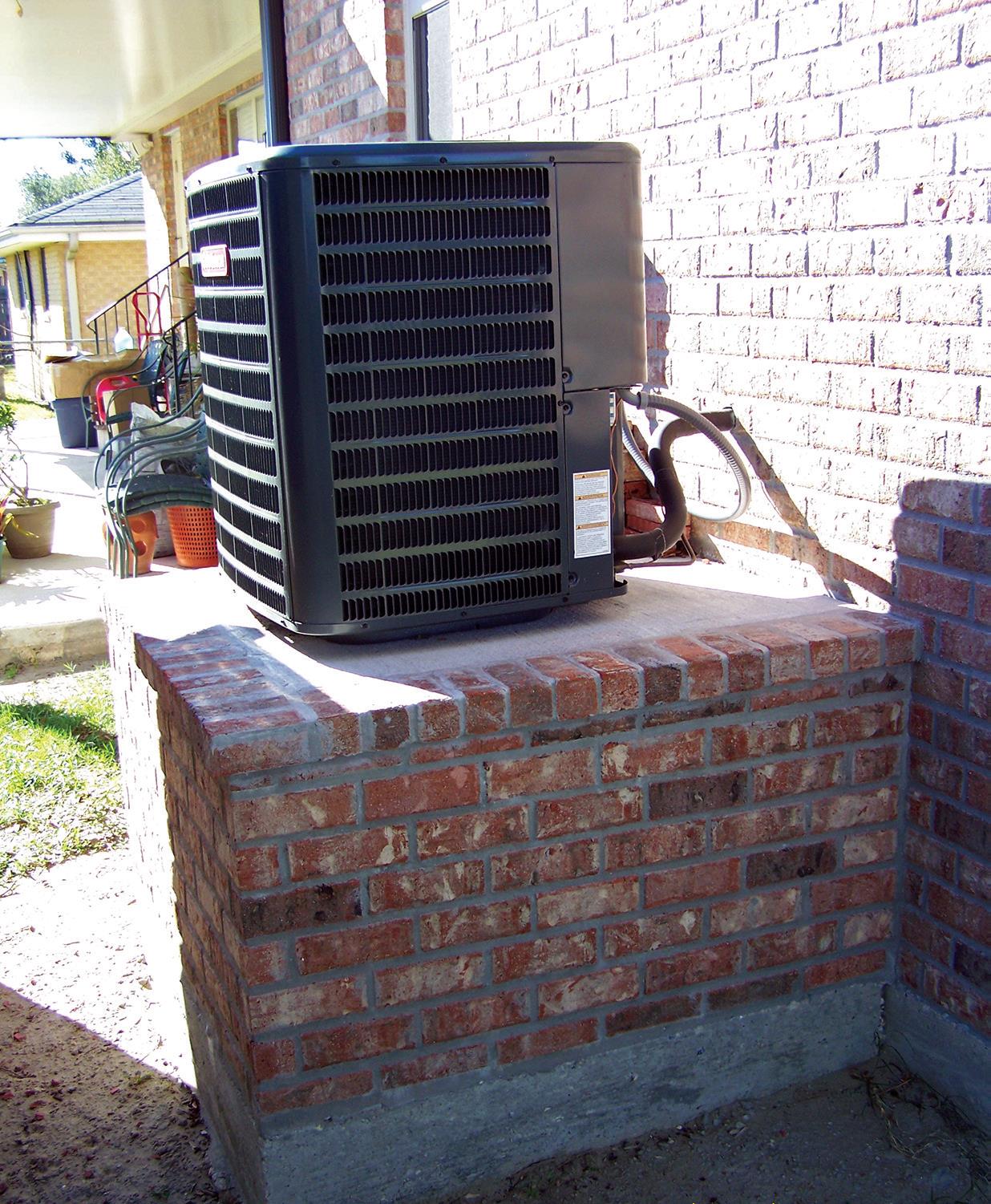
Right – The HVAC compressor is installed on a raised platform with a protective railing installed.
Image
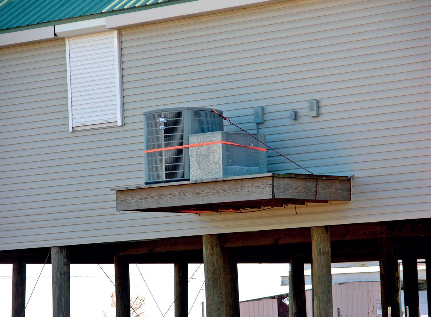
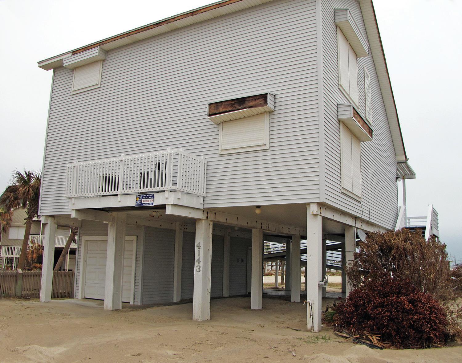
Right – The HVAC compressor sits on a raised cantilever platform away from the base flood elevation.
Image
Image
Right – The HVAC outdoor unit is anchored on a bed of masonry bricks, 1 foot or more above the base flood elevation.
Image
Right – The HVAC unit installed in the insulated attic uses a heat pump to provide heating and cooling while also providing dehumidification and fresh air ventilation.
Image
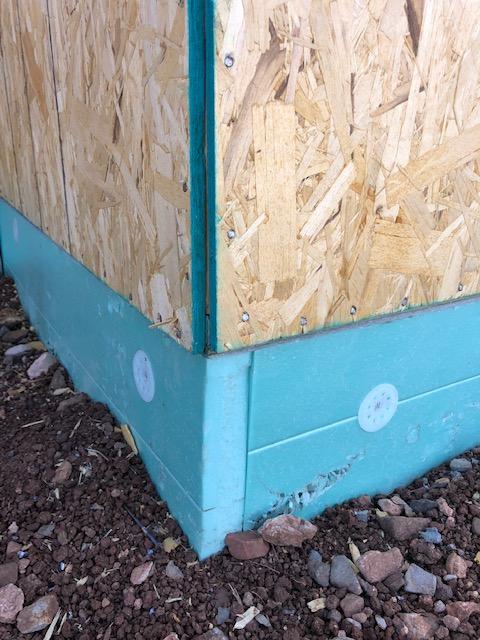
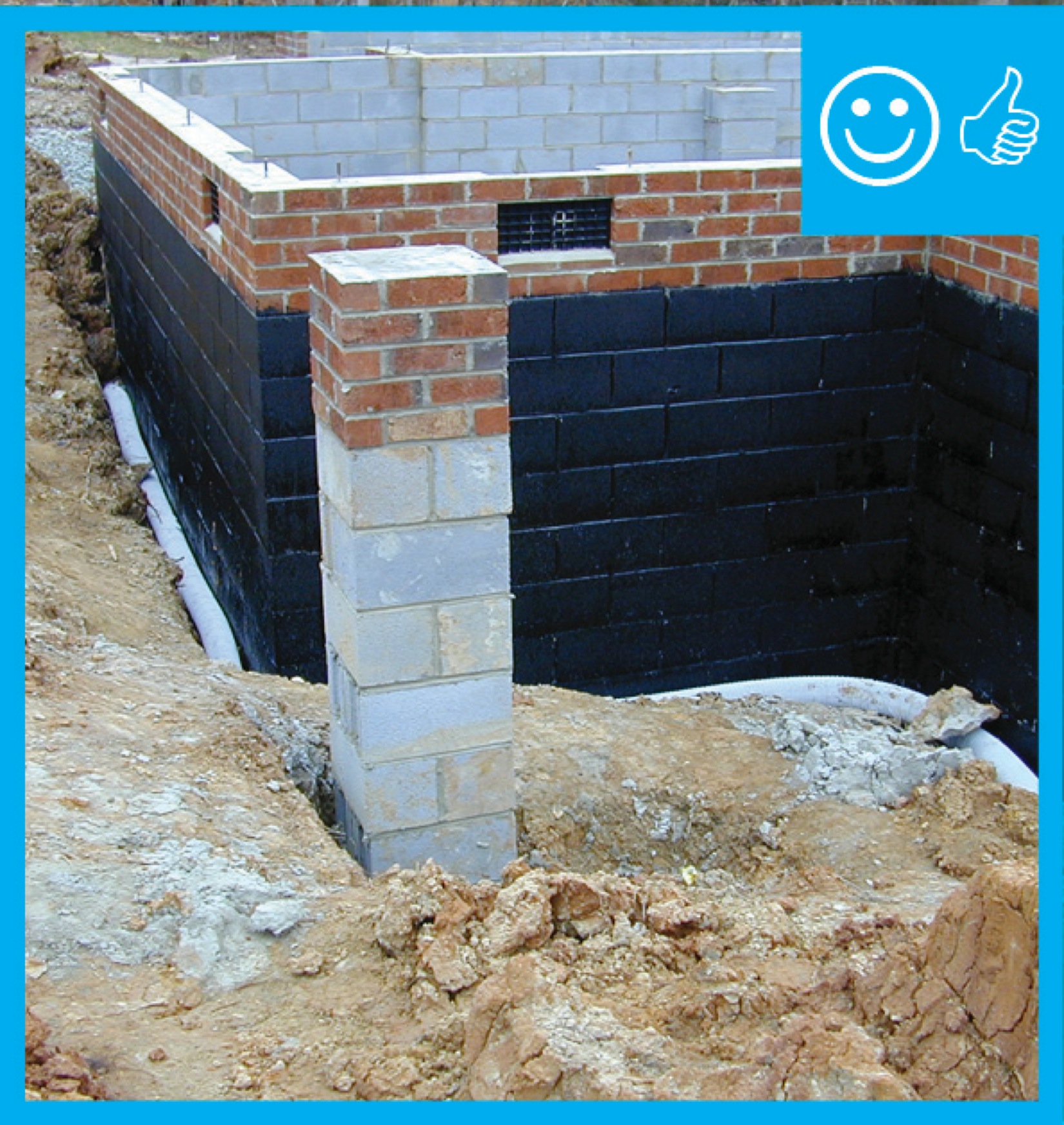
Right – The insulated concrete forms that are below-grade have a damp-proof coating to prevent moisture seeping into the foundation
Image
Right – The insulating enclosure over this non-IC rated recessed light fixture is centered and air sealed
Image
Right – The insulation has been located to the exterior of the thermal mass in this wall section
Image
Right – The joint between the foundation wall and the mud sill is thoroughly sealed with a liquid-applied sealant.
Image
Image
Right – The latticework between columns in this raised foundation will allow free flow of water in the event of a flood
Image
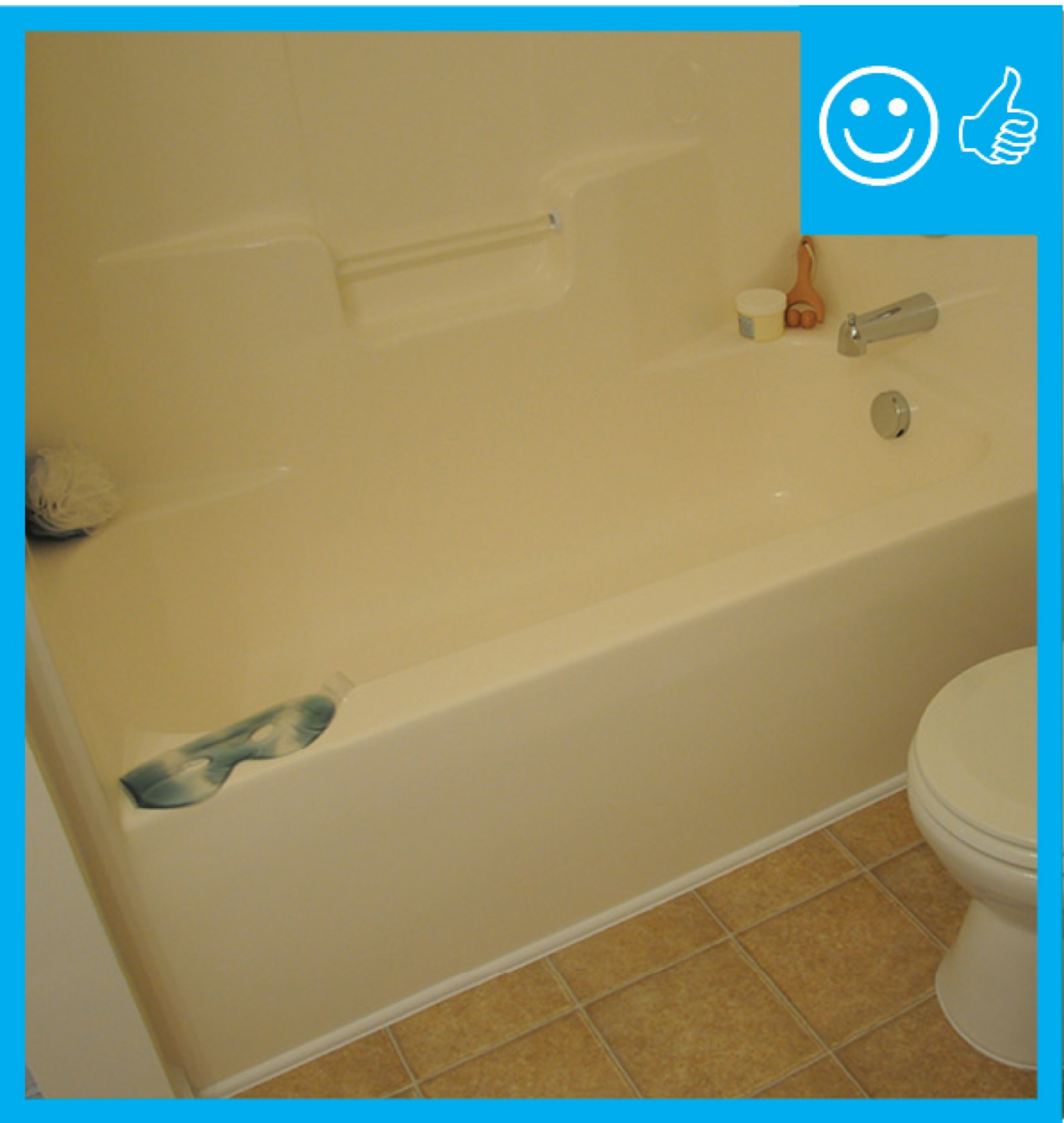
Right – The master bathroom has a handicapped-accessible shower with curbless entry and an adjustable-height hand shower.
Image
Right – The outside unit of the mini-split heat pump system is installed on a concrete pad and away from shrubs.
Image
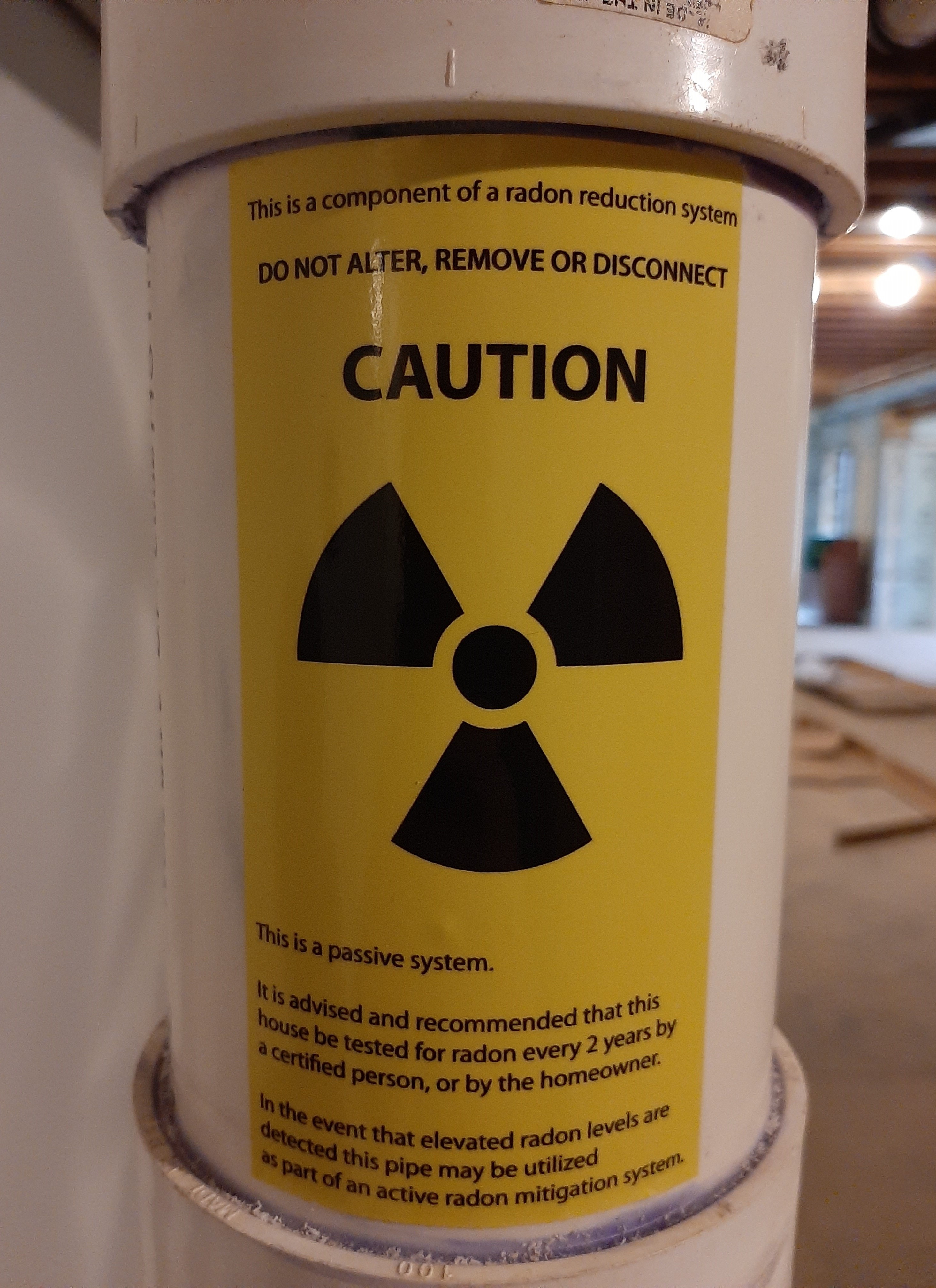
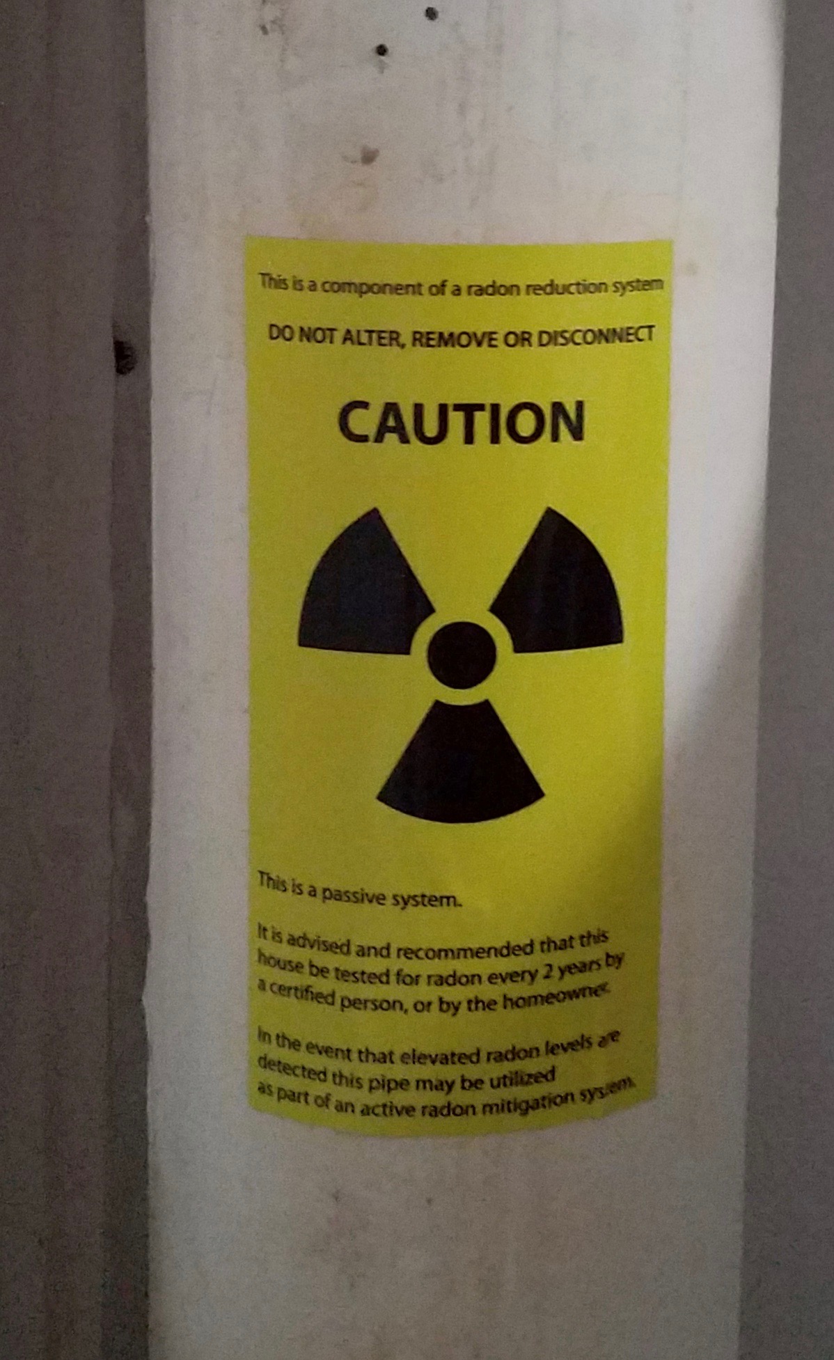
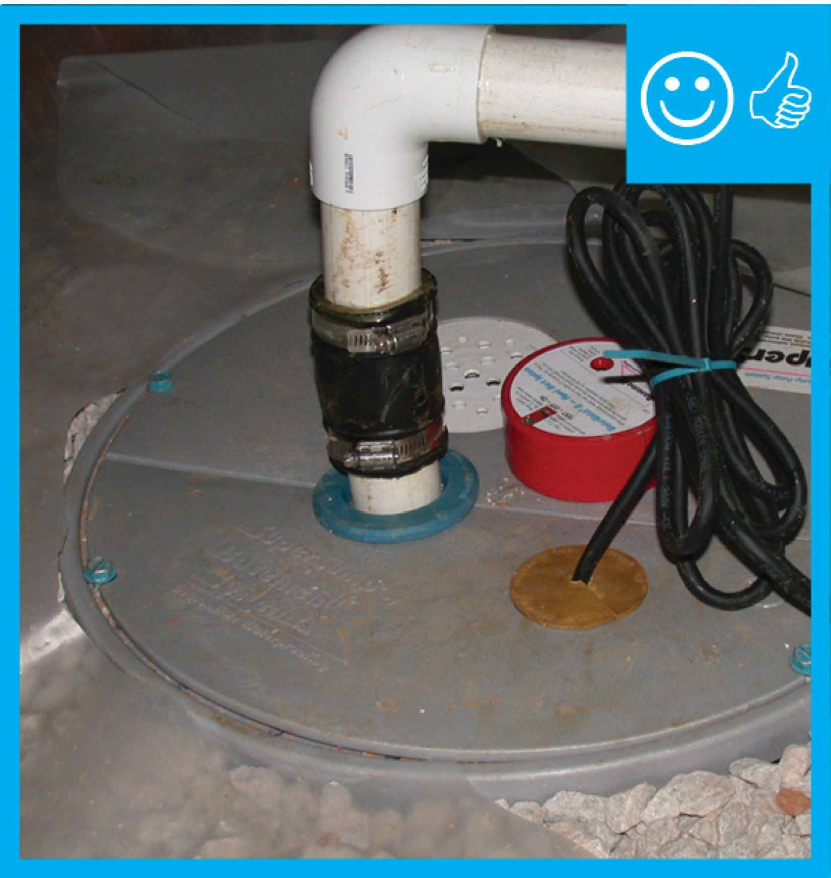
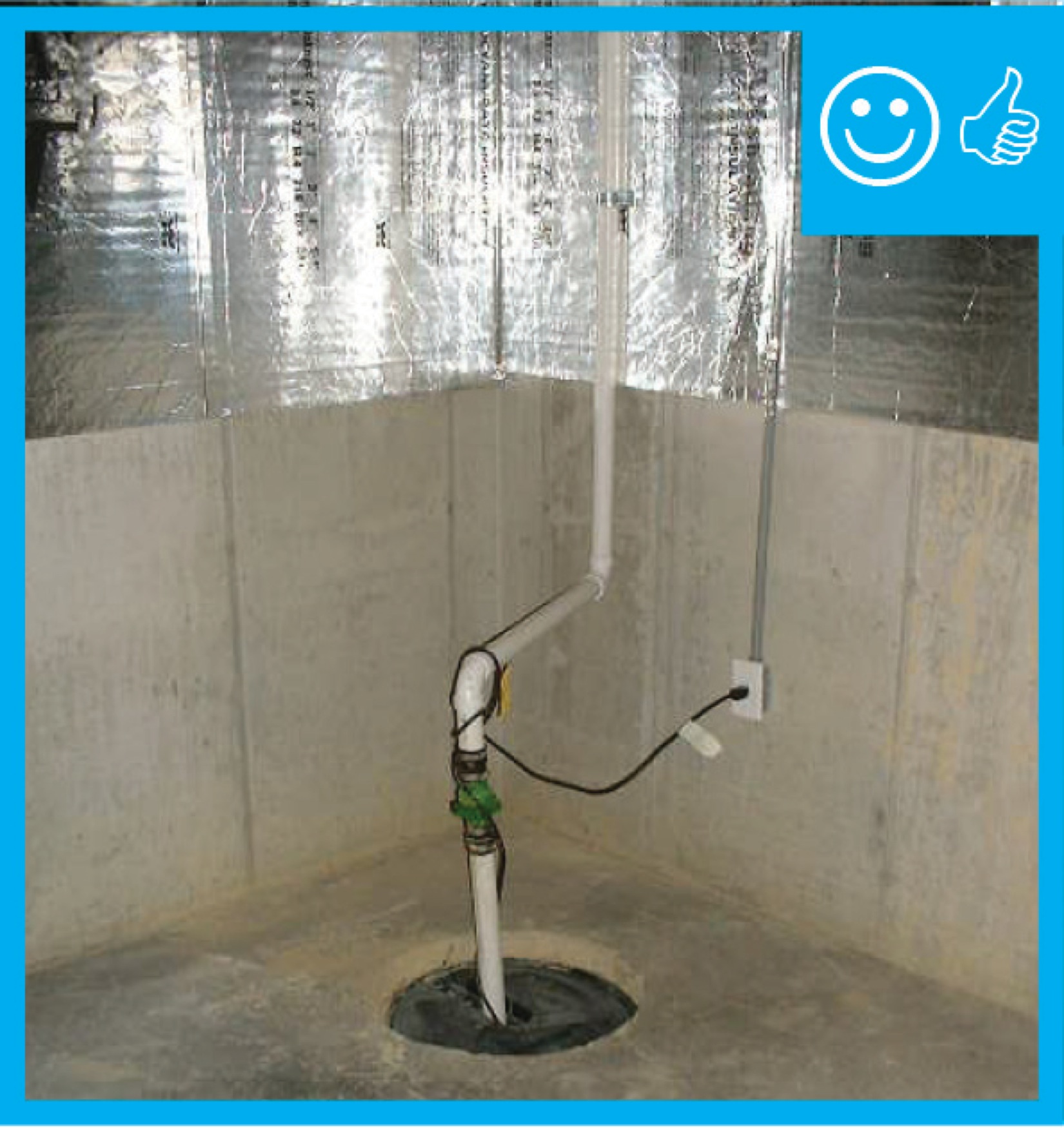
Right – The passive radon vent stack is properly labeled; this pipe brings radon and soil gases collected via a perforated pipe located under the floor slab up through an exterior wall for venting out through the roof.
Image

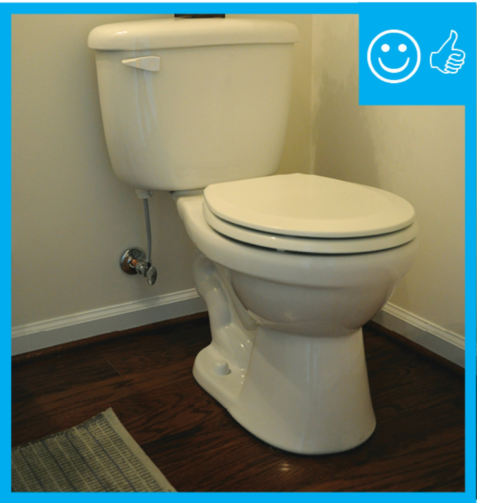
Right – The PEX piping and sink drain of this bathroom sink are fitted with escutcheons that help to air seal around the pipes and prevent pest entry.
Image

Image
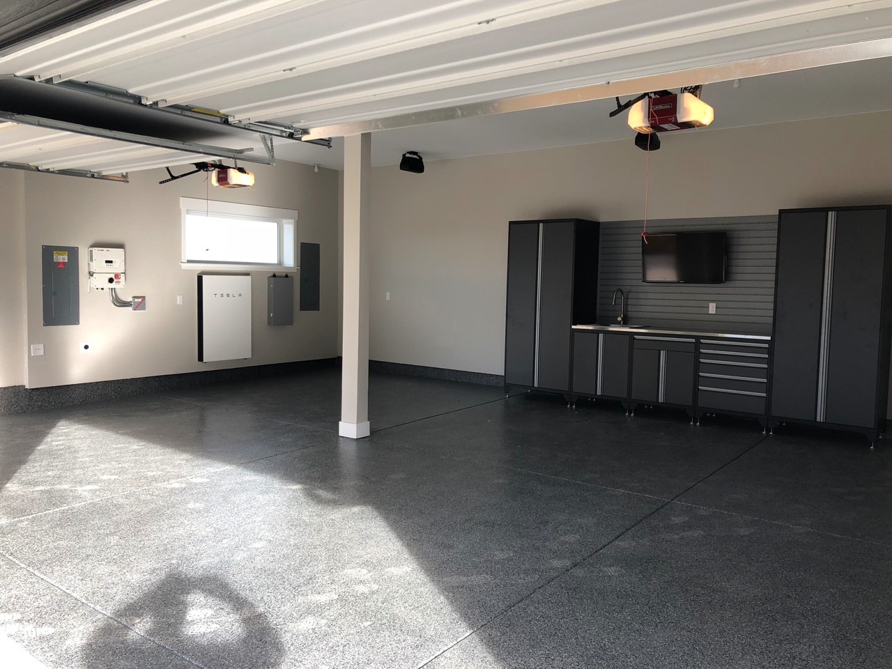
Right – The PV system inverters and battery take up minimal space in the garage.
Image
Image
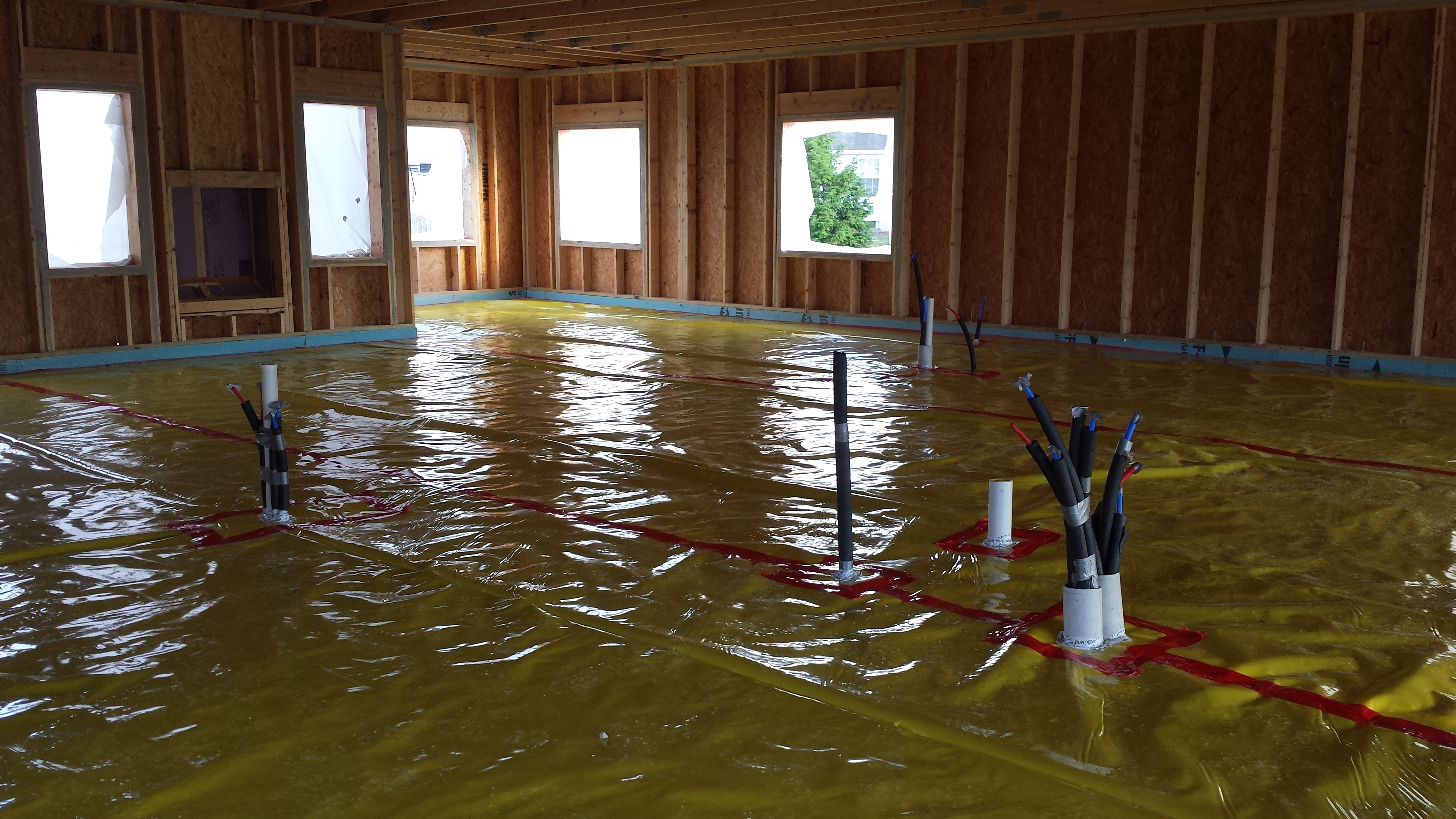
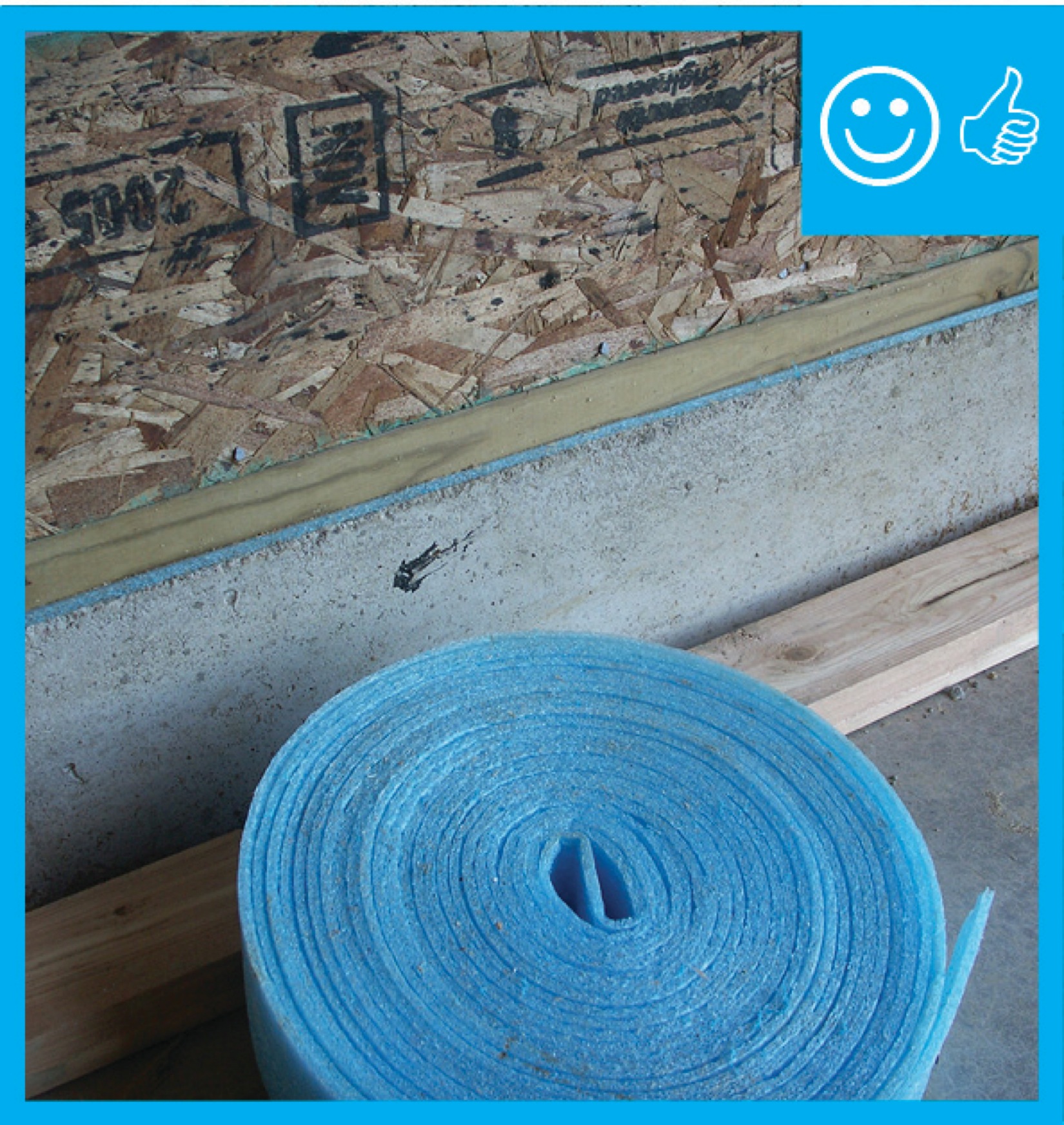
Right – The raised slab foundation has a 3-ft stem wall of filled concrete block, then is back-filled with compacted dirt and crushed rock, then insulated with 1” rigid foam covered with taped vapor barrier, under a floor slab.
Image

Right – The raised-slab, brick-and-block stem wall, above-grade walls, and roof of this house use flood damage-resistant materials, integrated water, vapor, and air control layers, and construction methods which promote good drainage and rapid drying
Image
Right – The raised-slab, CMU block stem wall, above-grade walls, and roof of this house use flood damage-resistant materials, integrated water, vapor, and air control layers, and construction methods which promote good drainage and rapid drying
Image
Right – The raised-slab, poured-concrete stem wall, above-grade walls, and roof of this house use flood damage-resistant materials, integrated water, vapor, and air control layers, and construction methods which promote good drainage and rapid drying
Image
Image
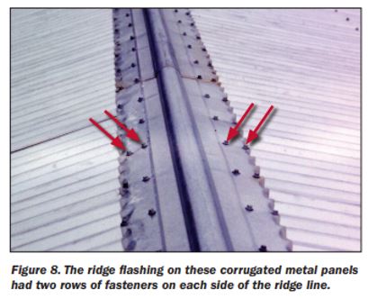
Right – The ridge flashing is secured with two rows of fasteners on each side of the ridge line
Image
Right – The rigid insulation covers all exterior walls and all seams are taped to provide a complete drainage system
Image
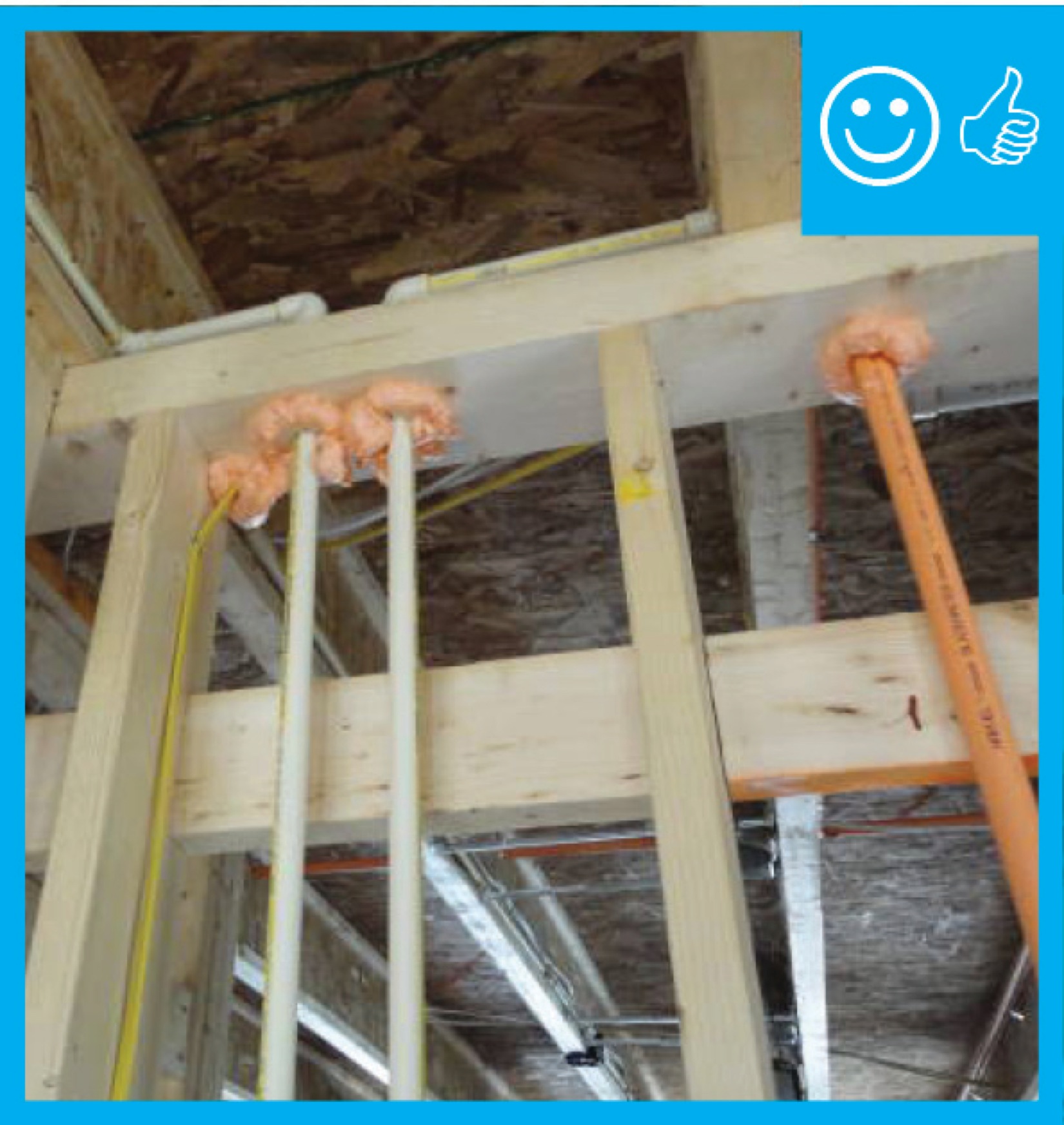
Right – The rim joists above the pre-insulated basement walls are sealed and insulated with spray foam to prevent air leakage at this juncture in the building envelope.
Image
Right – The roof membrane is fully adhered and deck seams are sealed so the membrane will not flutter and fail due to negative pressure from high winds
Image
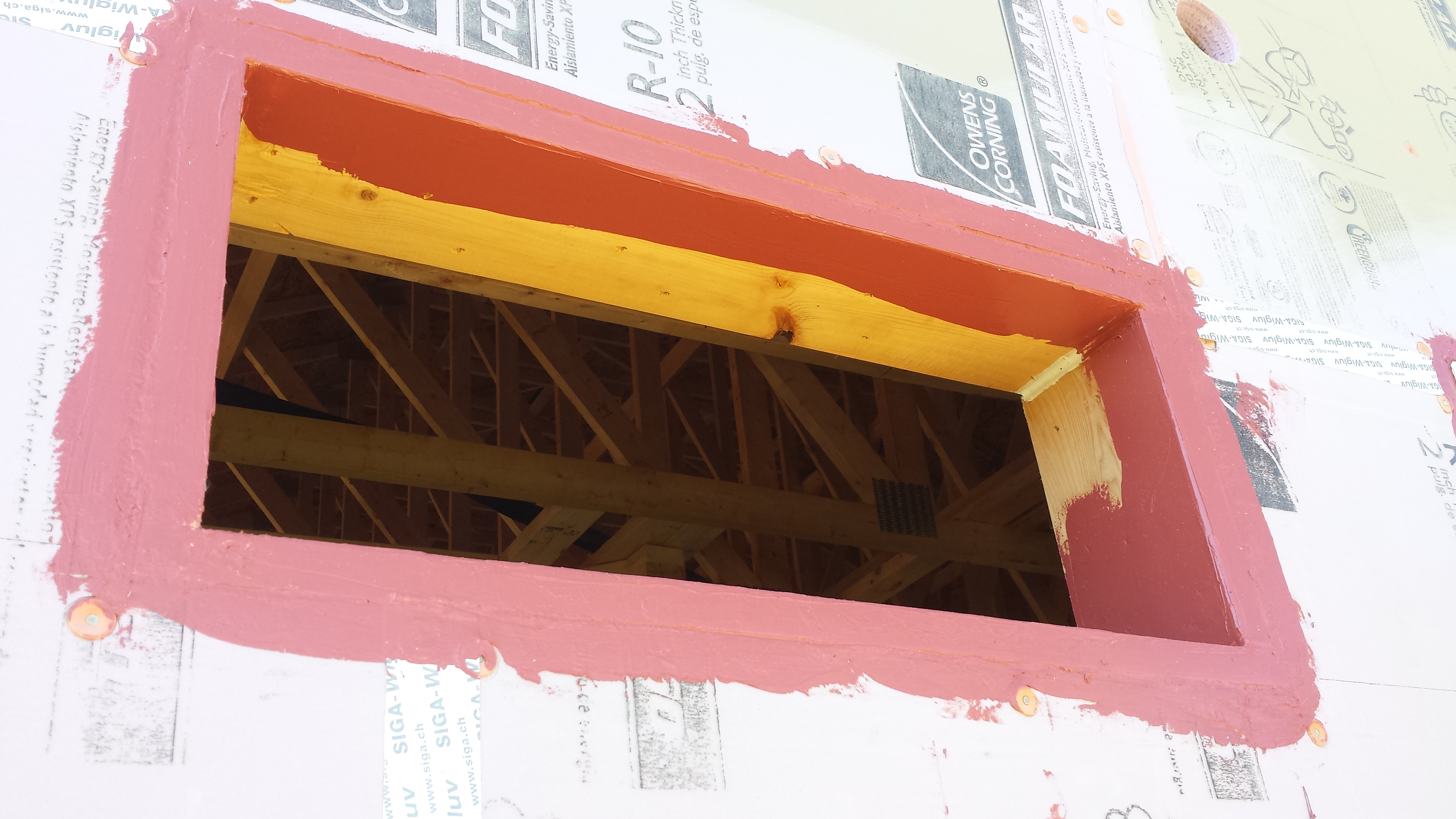
Right – The rough opening around the window has been filled with low-expansion foam to air seal.
Image

Right – The rough opening around window has been filled with backer-rod to air seal.
Image
Image
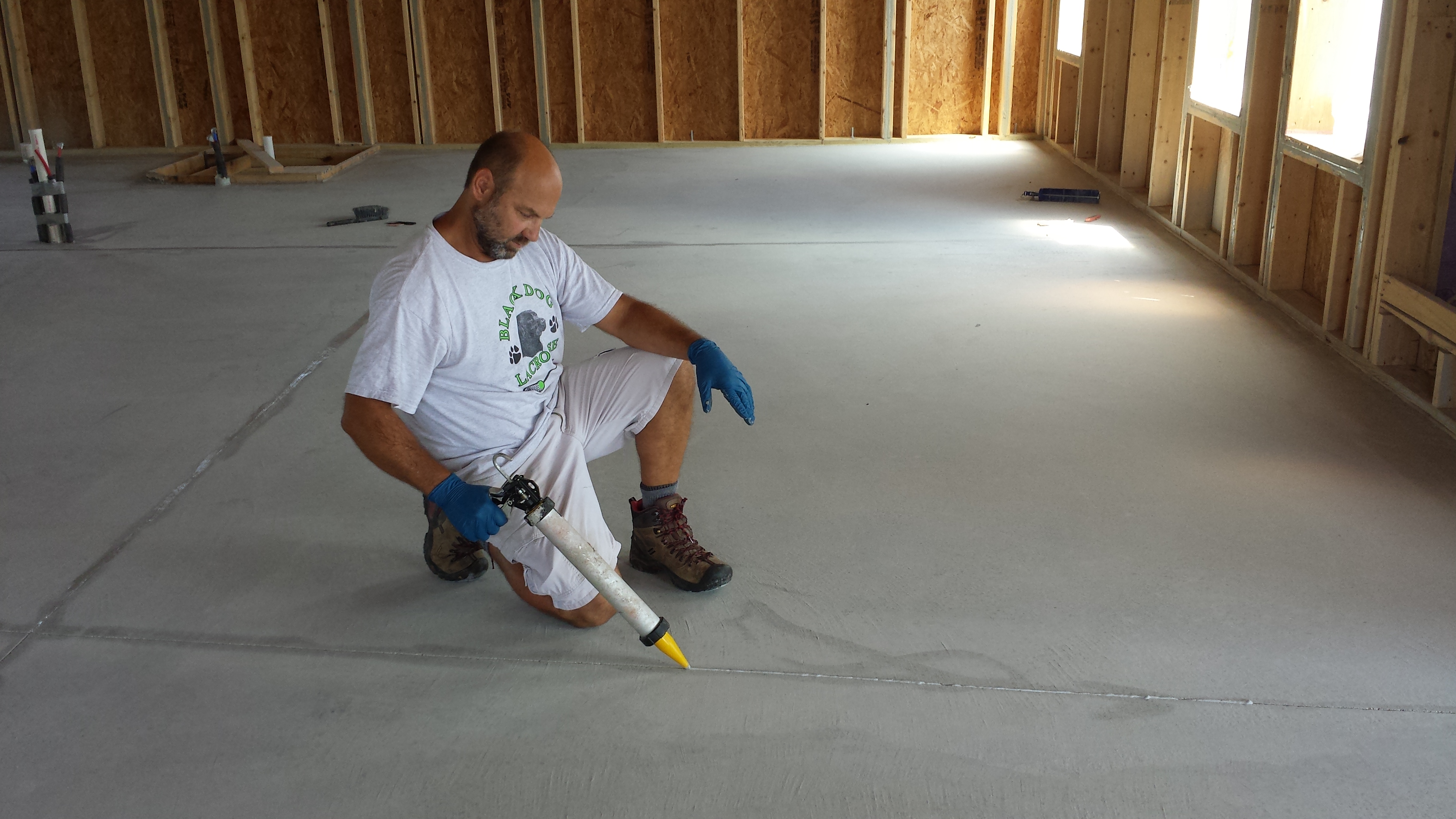
Right – The seam between the slab and the foundation wall is sealed with urethane caulk.
Image
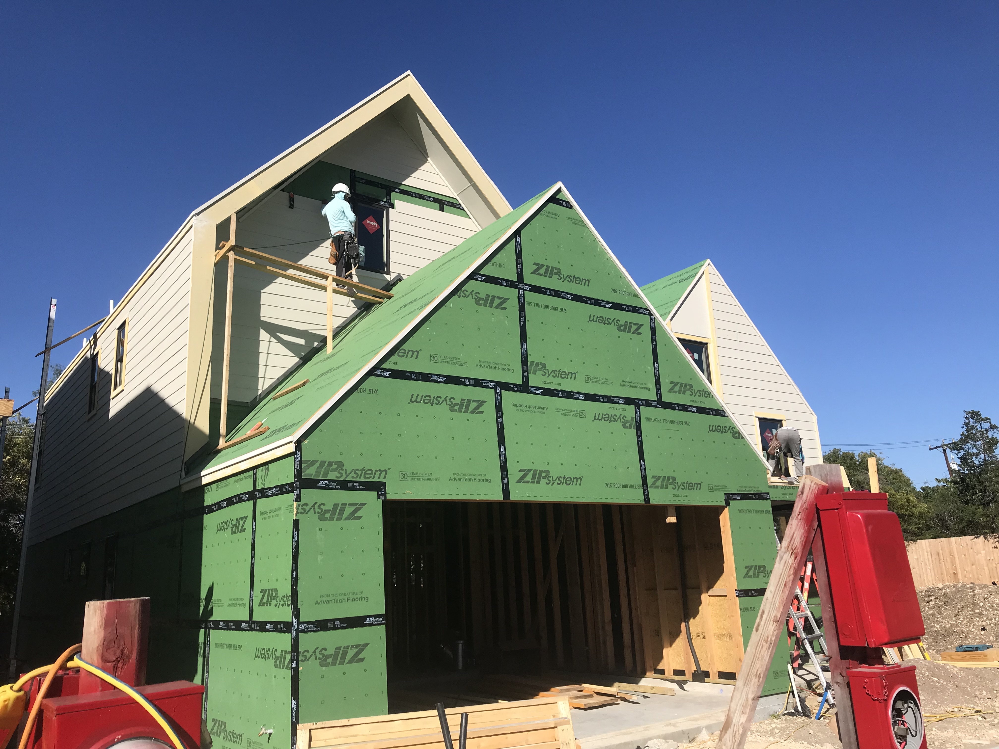
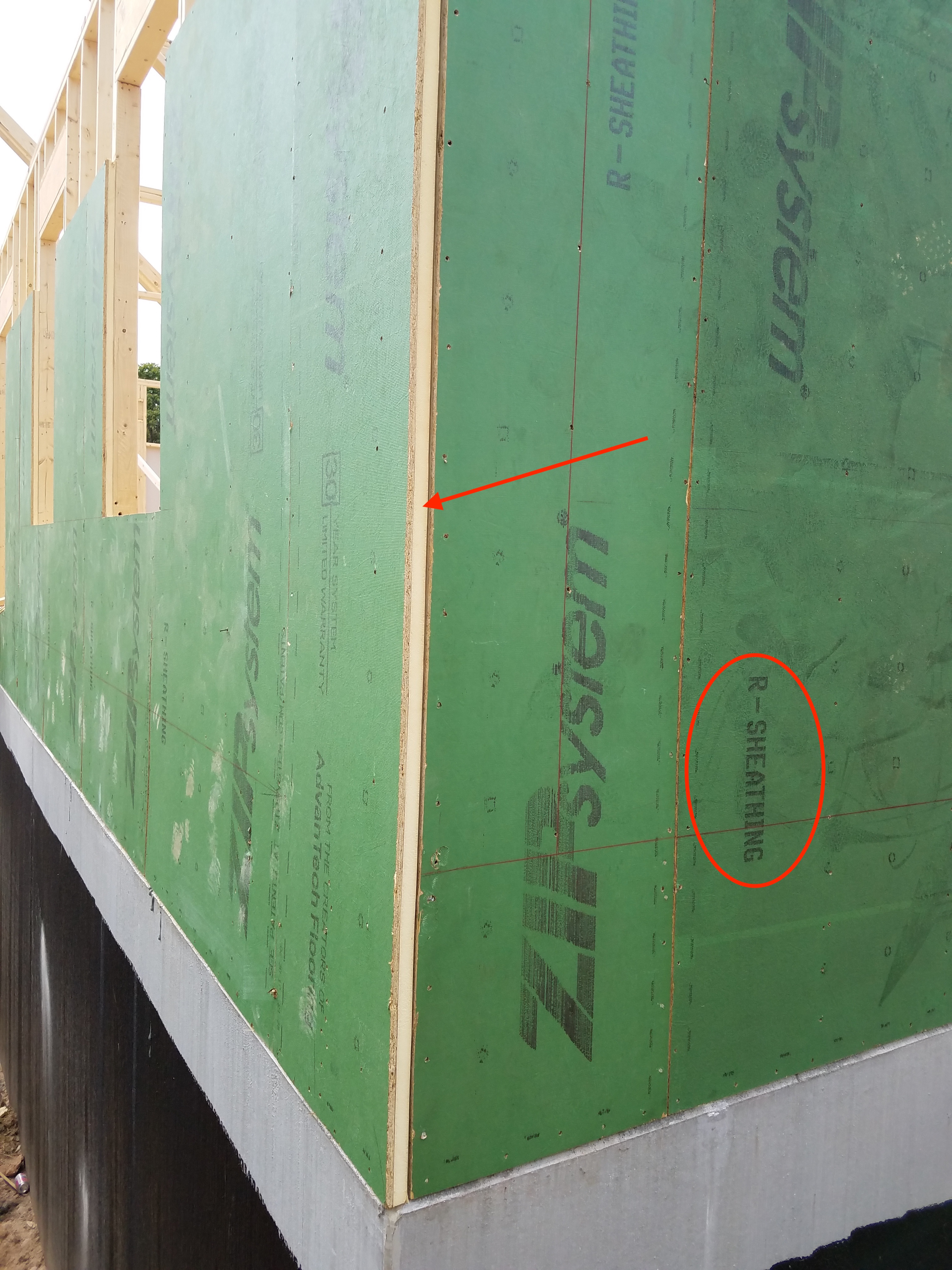
Right – The seams are taped on the coated OSB sheathing of this home to provide a complete air barrier.
Image

Image
Right – The sill plate was sprayed with foam prior to installation atop foundation.
Image
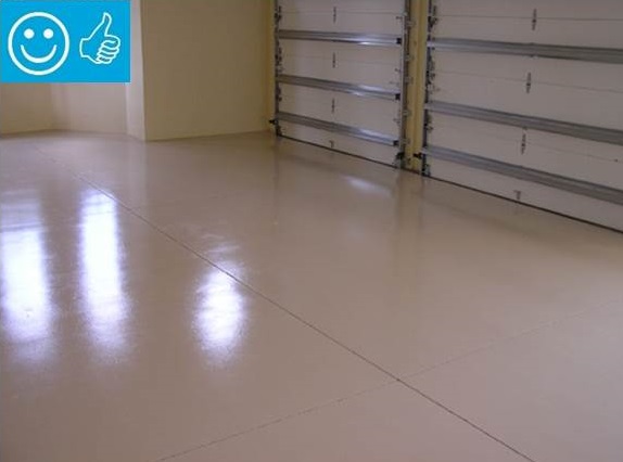
Right – The slab is coated with two coats of epoxy paint to minimize moisture transfer through the slab from the ground.
Image
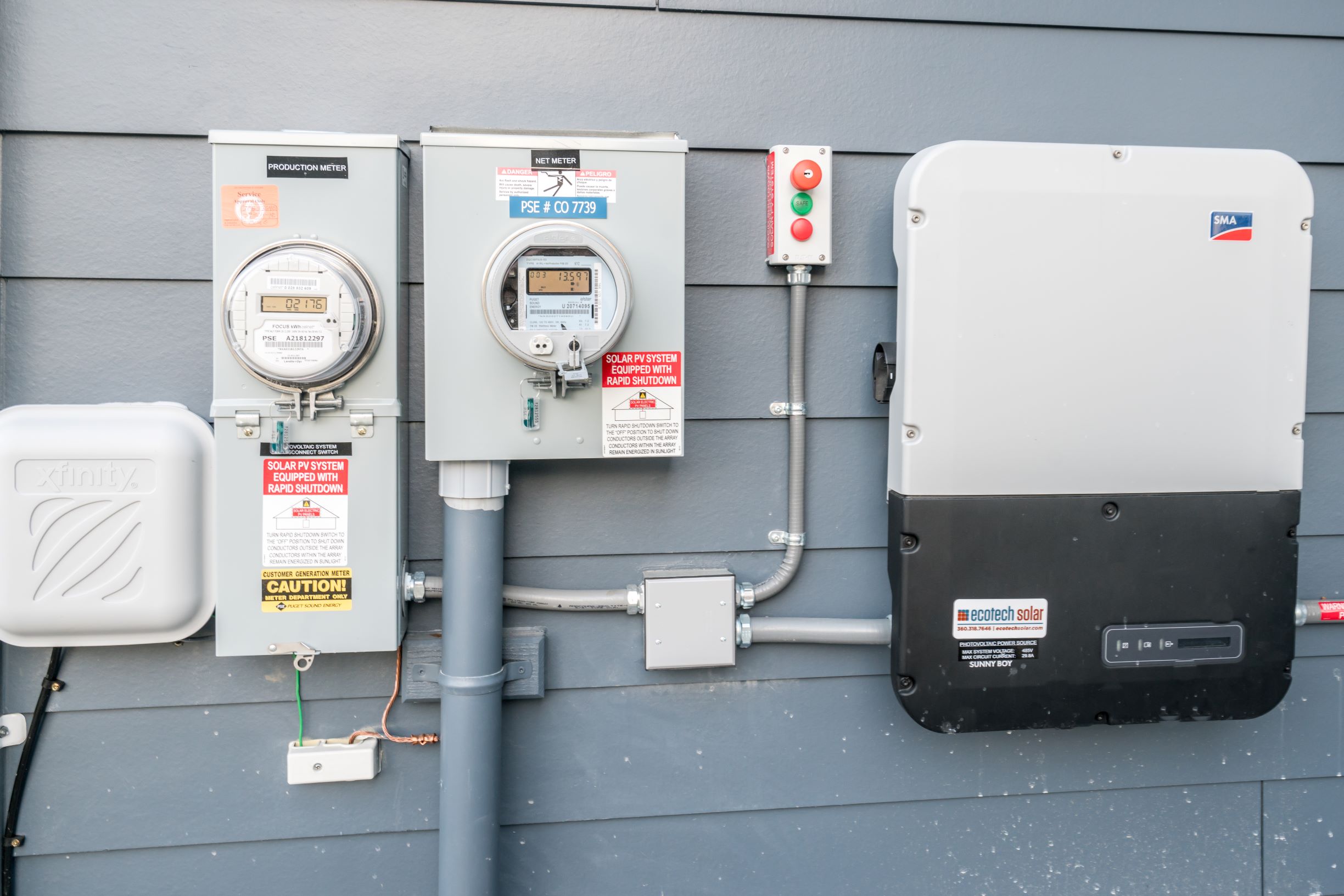
Right – The solar system production is tracked next to the home’s electrical meter.
Image
Right – The spacer structure of these ICFs provides supports for attaching the fasteners used to attach the metal studs of the below-grade walls.
Image
Image
Image
Image

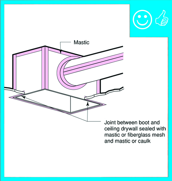
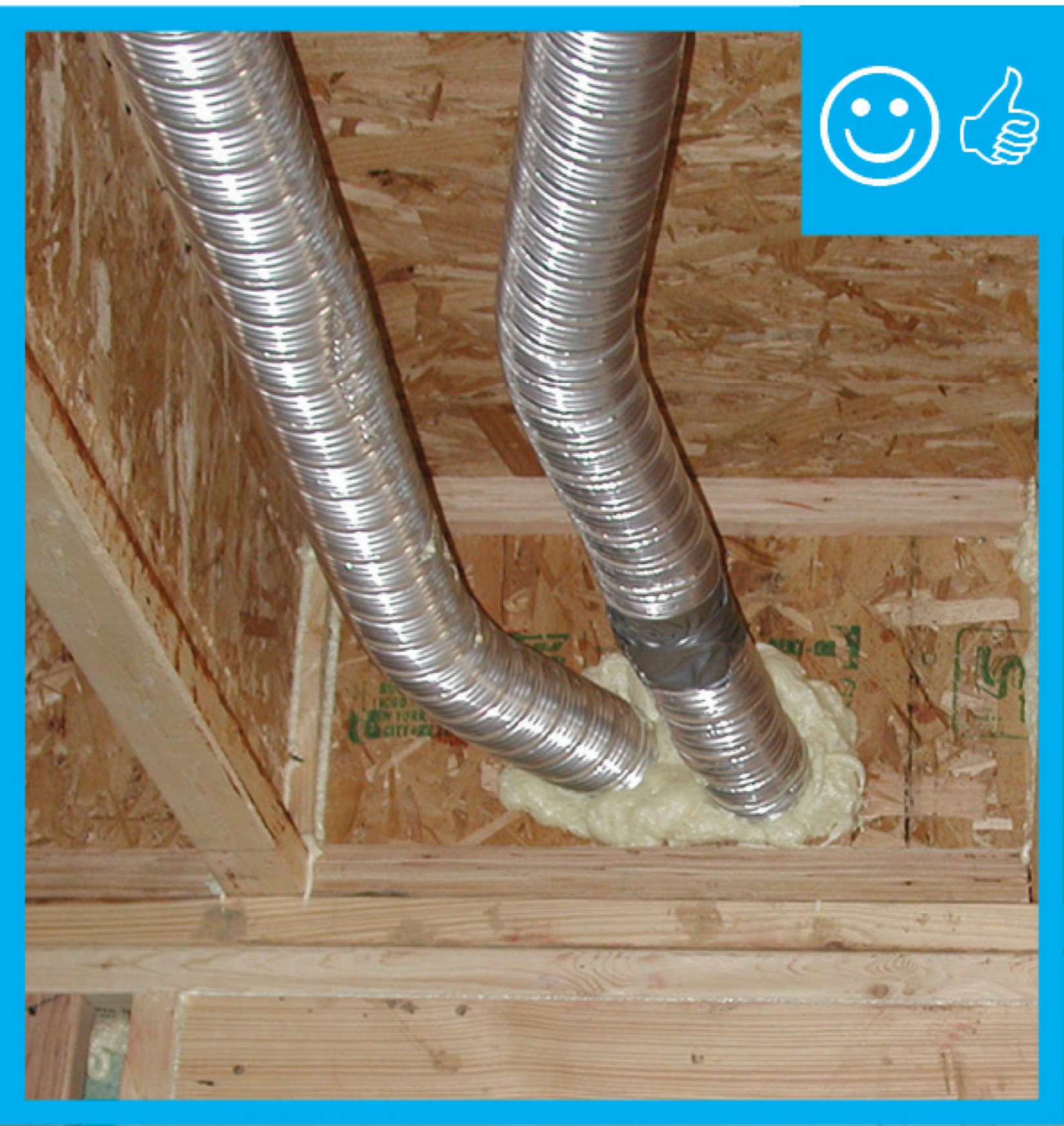
Right – The termination of this kitchen exhaust duct is sealed to the wall to keep out air and water and is screened to keep out pests.
Image
Right – The top of the enclosure over this recessed can light remains clear of attic insulation
Image
Right – The top plate-to-dry wall seams of the interior walls are sealed from the attic.
Image
Right – The underside of this low-sloped roof is insulated with open-cell spray foam in this dry climate to achieve the code-required R-value; the builder used the same foam to insulate exterior walls.
Image
Image
Right – The walls of this home were constructed with “insulated studs” fashioned on site by adding 2-inch-thick strips of rigid foam to the inside face of 2x4 studs then topping that with a plywood nailing surface.
Image
Right – The water-resistant barrier covers the entire house and the seams are taped to provide a complete drainage system
Image
Right – The water-resistant barrier is layered over the step flashing to provide a complete drainage system
Image
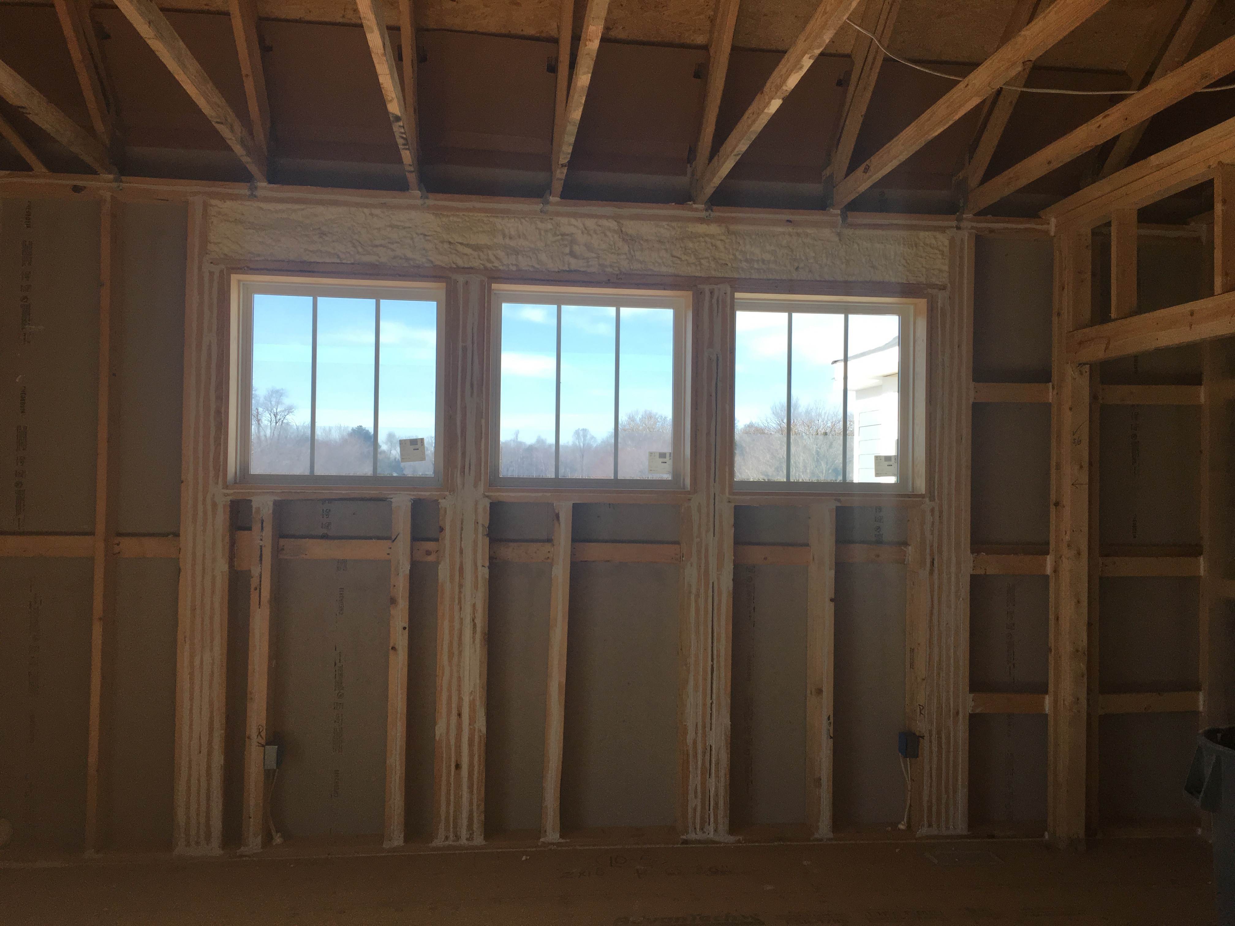
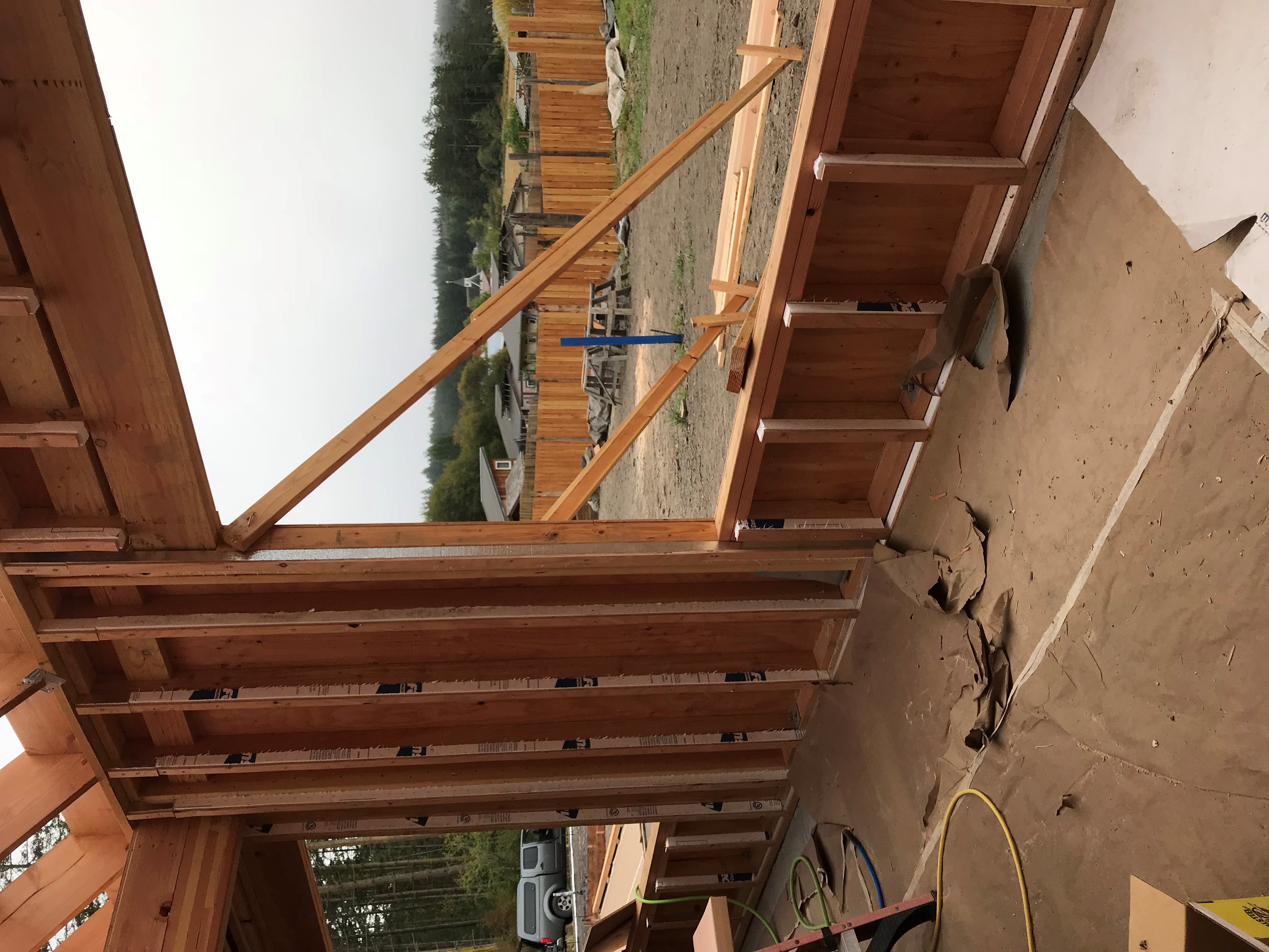
Right – The window header is filled with spray foam and sealant is used to air seal wood-to-wood seams; however, it would be preferable to design the wall to avoid so many stacked studs around the windows because they prevent wall insulation installation.
Image
Image
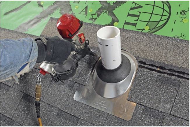
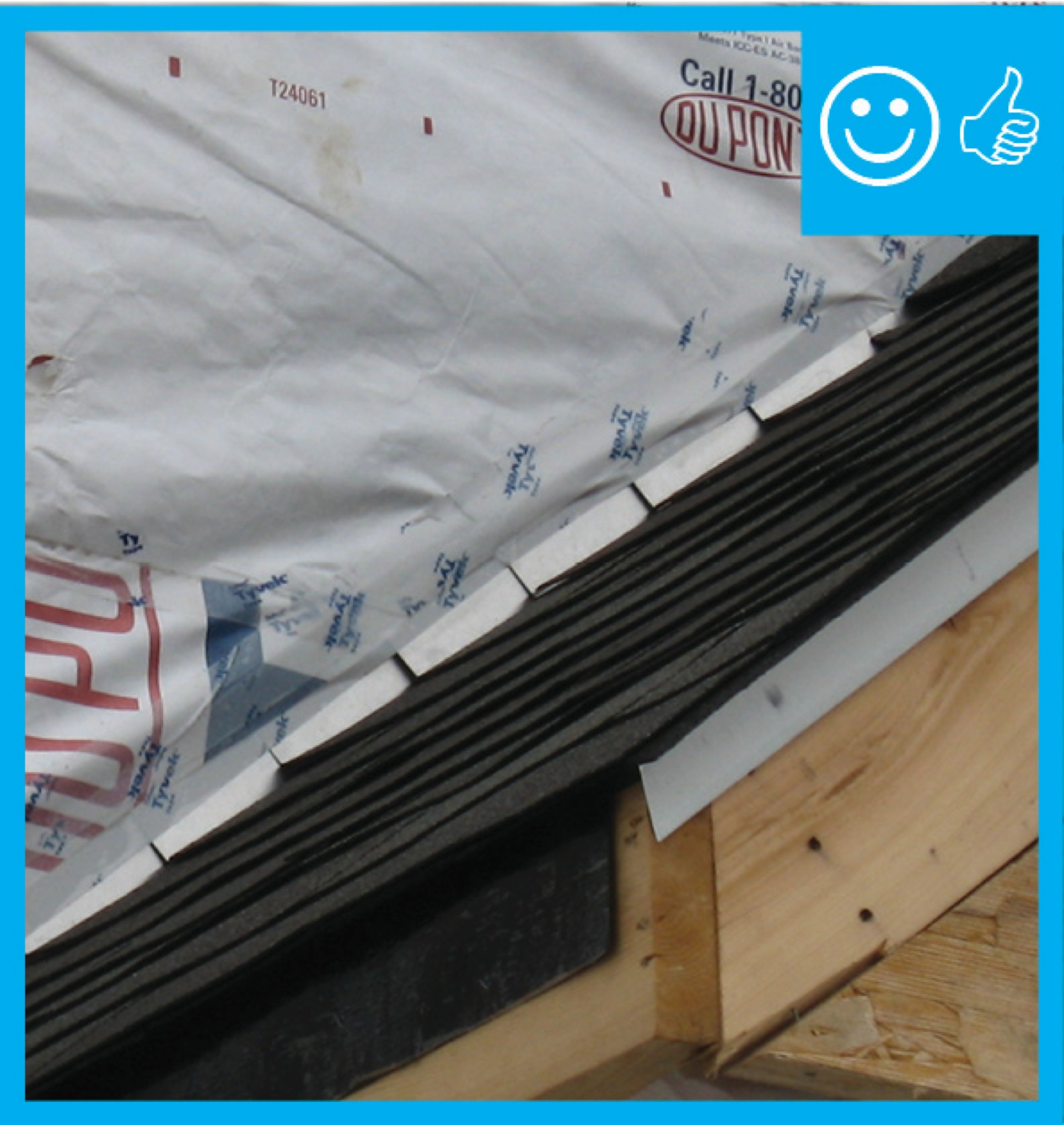
Right – There is a properly installed and layered self-sealing bituminous membrane at the roof penetration
Image
Right – There is a self-sealing bituminous membrane installed at the valley of the roof prior to the roof felt
Image
Right – There is flashing installed along the top of the window and the water-resistant barrier is layered over to create a complete drainage system
Image
Right – There is flashing installed at the bottom of the wall to create a satisfactory drainage system
Image
Image
Image
Right – thermal mass walls, small windows, and recessed porch and trees on the south side of this southwest home help to minimize solar heat gain.
Image
Right – These modular homes are constructed in a factory and will be trucked to the site for installation on a permanent foundation.
Image
Right – These modular homes are constructed in a factory that provides easy, ergonomic access to typically hard-to-reach areas of the home including under the floor.
Image
Image

Right – These three urban-infill cold-climate homes were built on insulated concrete foundations.
Image
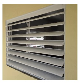
Right – This aluminum jalousie window provides solar control while allowing view and ventilation.
Image

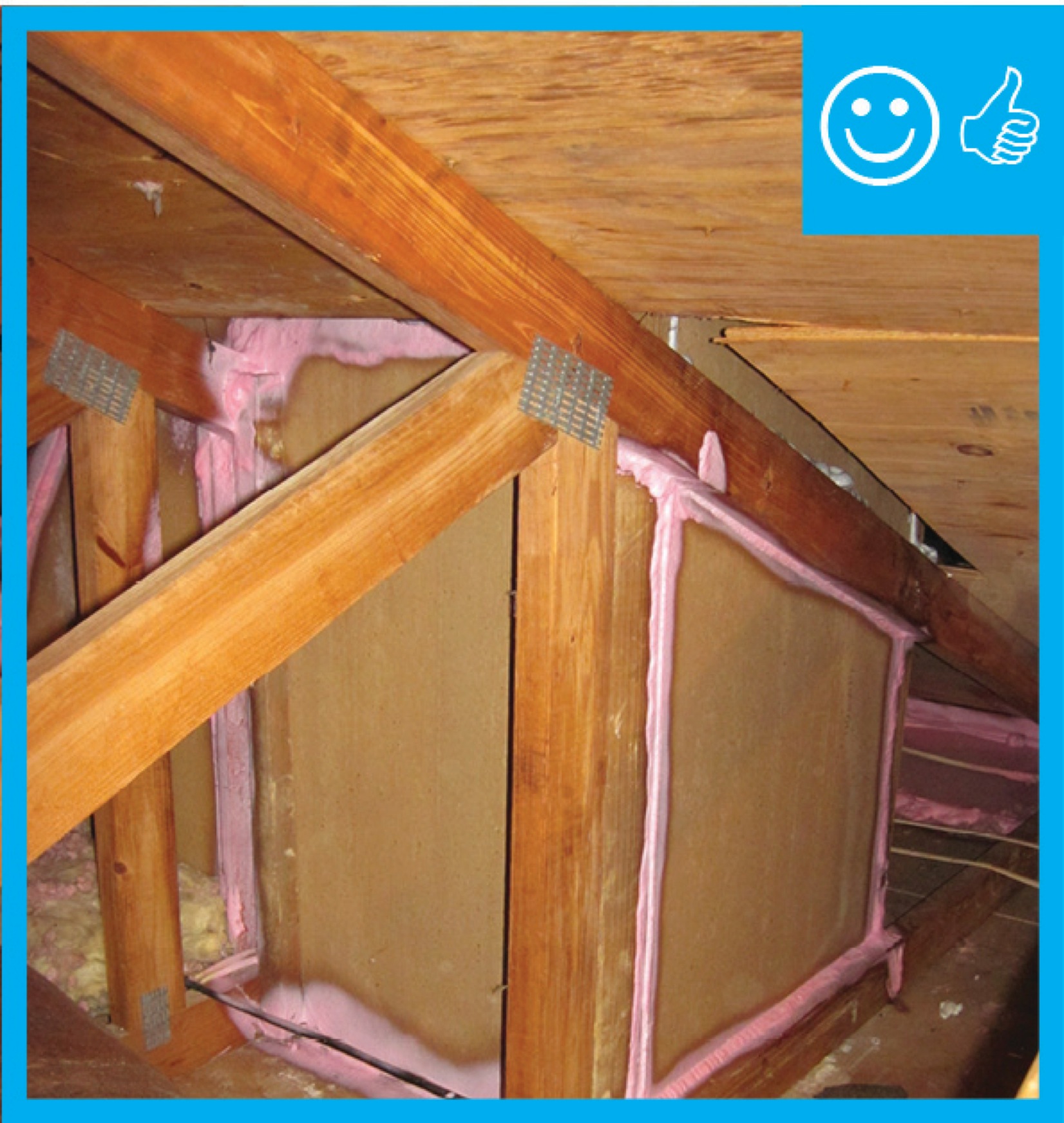
Right – This attic knee wall and the floor joist cavity openings beneath it are being sealed and insulated with spray foam.
Image
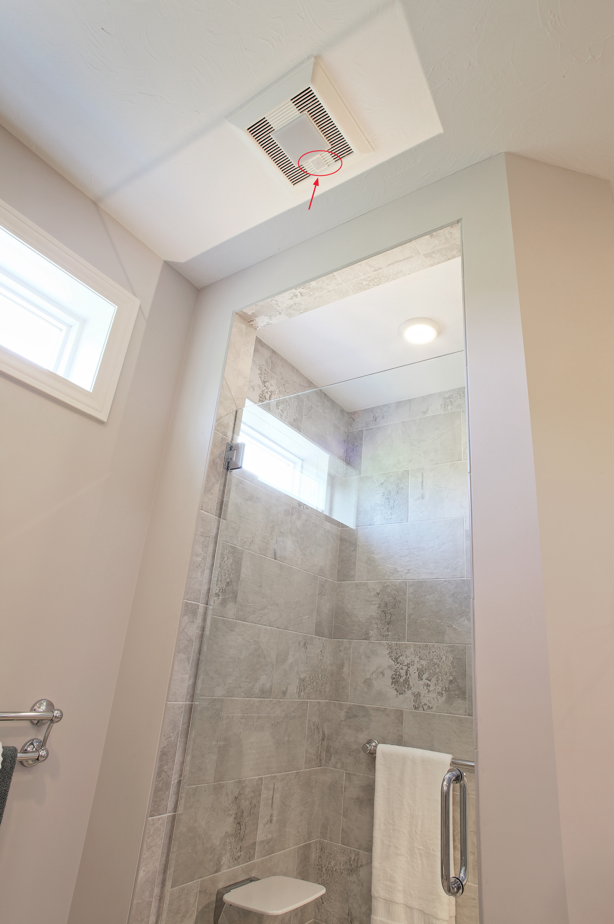
Right – This bath fan runs continuously at low speed and is activated by a motion sensor to operate a higher speeds.
Image
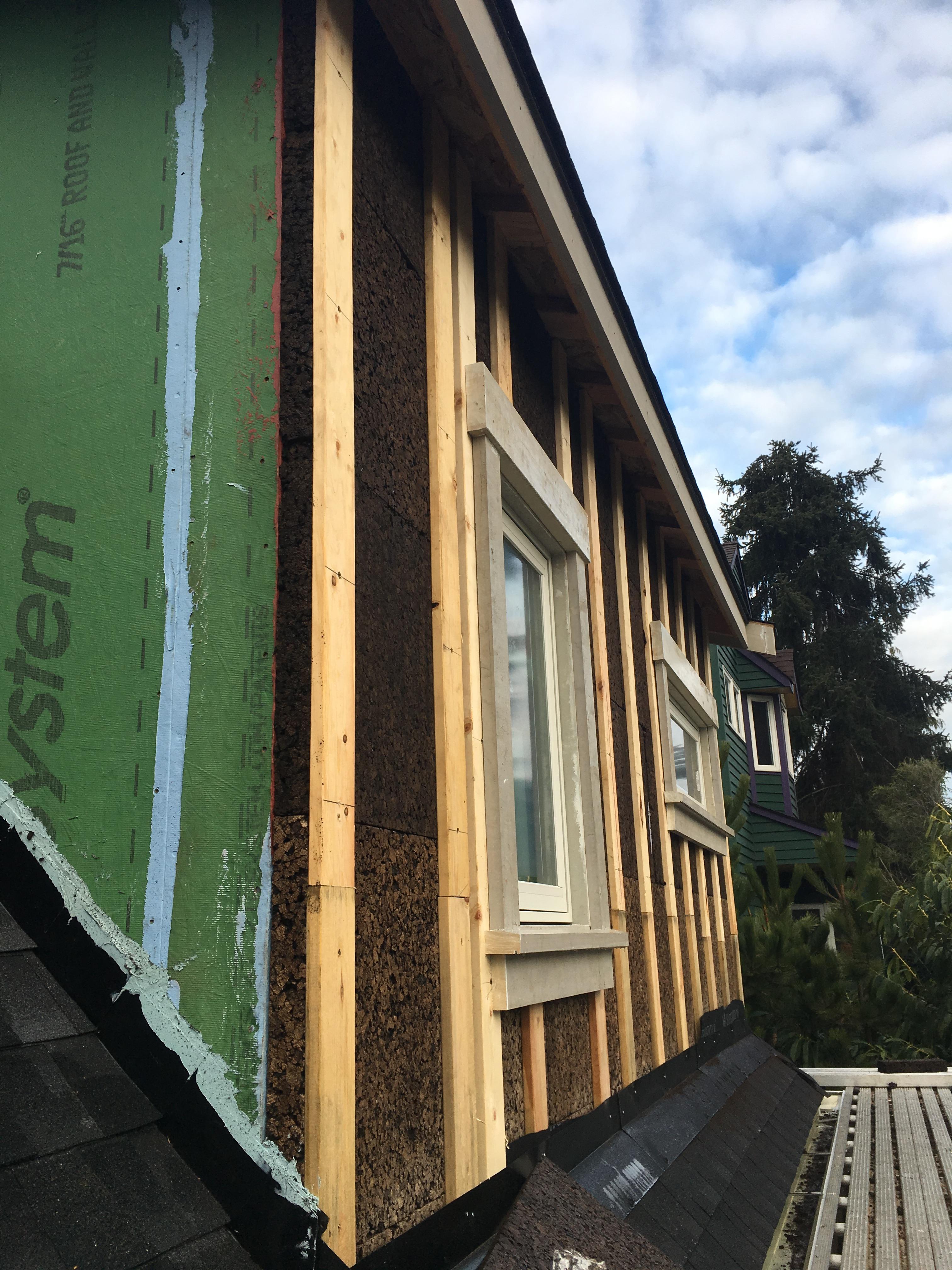
Right – This builder installs 1 inch of XPS rigid foam on the exterior of the 2x6 walls then covers the foam with ½-inch plywood sheathing, which serves as a nailing surface for siding and trim.
Image
Right – This coated OSB sheathing product is available with an integrated insulation layer.
Image

Right – This column foundation has no HVAC equipment, piping, electrical components, or structural walls below the elevated floor system
Image
Right – this commercial building employs good techniques to resist solar heat gain: awnings and pergolas over windows, recessed windows and entryways, deep tinting on glass, and shade plants.
Image
Image
Right – This crawlspace window was completely sealed off on the inside and outside with air barrier and water-proof materials and the window well was filled in to an above-grade height to prevent bulk water from entering the crawlspace
Image

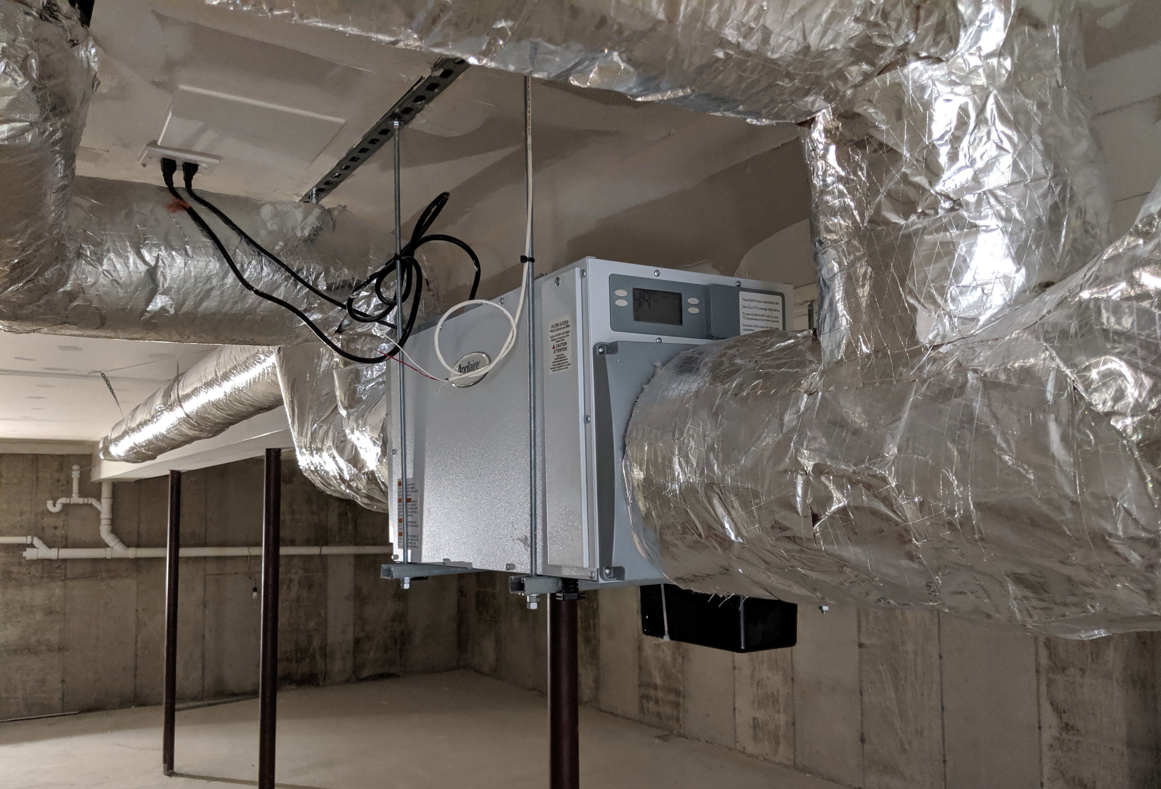
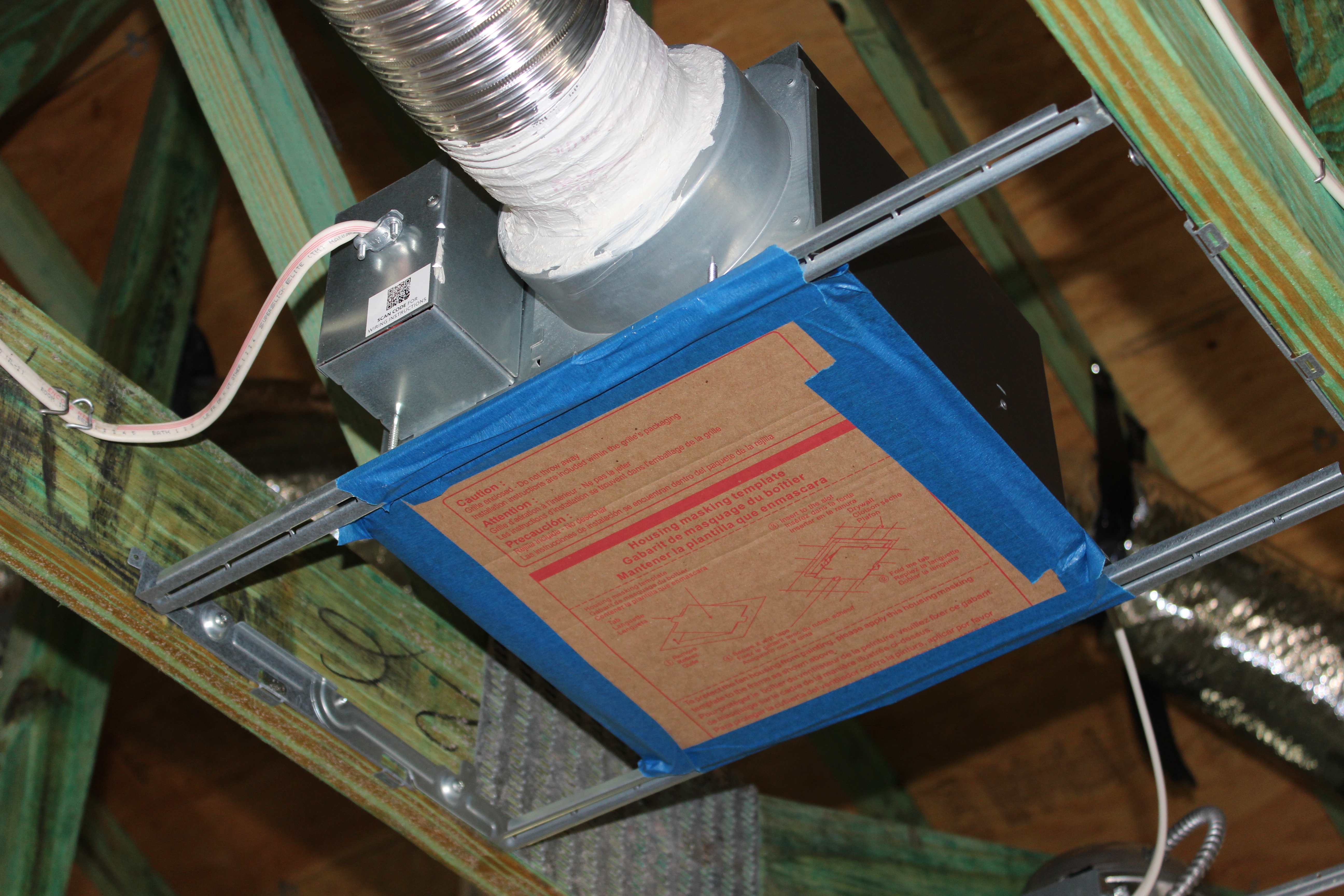
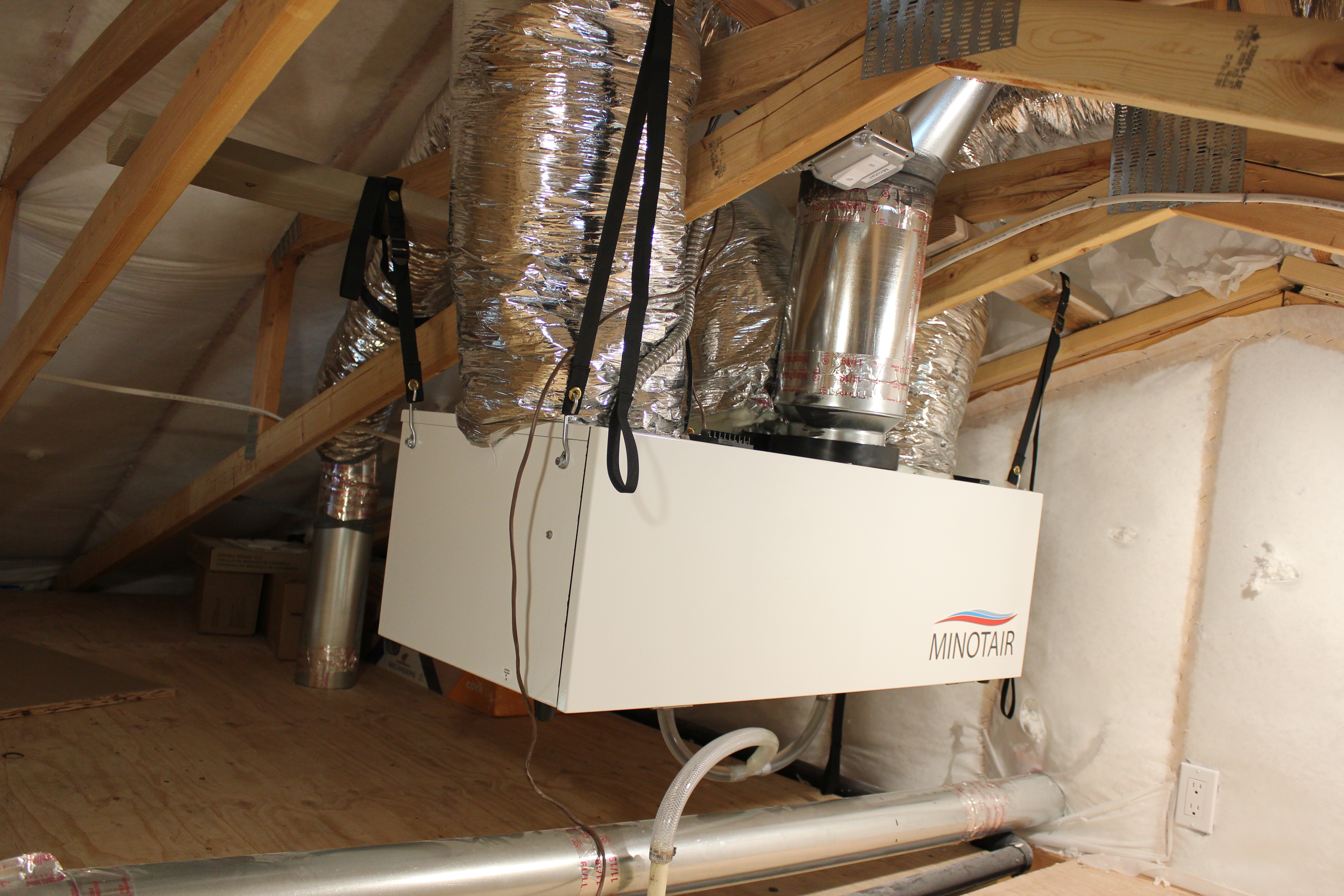
Right – This energy recovery ventilator provides fresh air and exhausts stale air through a heat exchanger that recovers heat from the outgoing air in winter and reduces heat from incoming air in the summer to provide ventilation without wasting energy.
Image
Right – This exhaust fan duct is made of smooth rigid metal and the duct is mastic sealed at the joints.
Image

Right – This exhaust fan use metal ducting that goes directly to the soffit to minimize penetrations through the roof.
Image
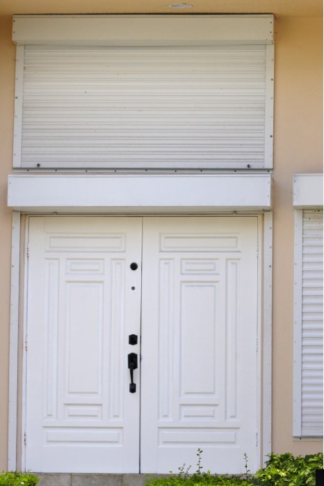
Right – This exterior door is installed to swing out and has storm protection shutters.
Image
Right – This fire-rated wall assembly uses exterior gypsum board and an exterior siding of fiber-cement or metal to increase fire resistance.
Image
Right – This floor system on a column foundation is insulated using closed-cell spray foam rather than fibrous insulation
Image
Right – This foil-faced foam sheathing has taped seams and proper flashing details so it can serve as a drainage plane.
Image
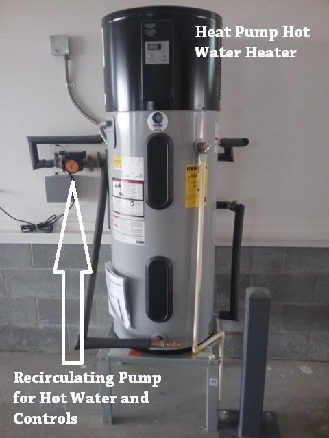
Right – This heat pump water heater is equipped with a recirculation pump to speed hot water to distant faucets.
Image
Image
Right – This home is framed with double walls – two 2x4 walls set next to each other then sheathed with OSB on the exterior and netted on the interior face to create an extra-deep wall cavity that can be filled with blown-in insulation.
Image

Right – This home solar system includes batteries that provide power during peak evening hours.
Image
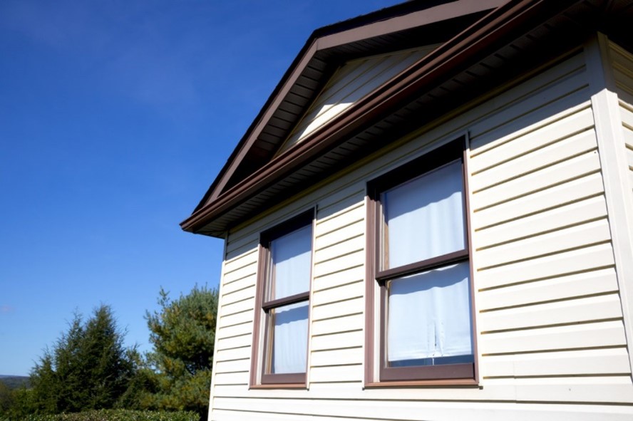
Right – This home uses a light-colored exterior wall to reduce solar heat gain
Image

Right – This home uses a small-diameter high-velocity duct system with a main duct (plenum) that is one-fourth the size of a conventional duct and branch ducts with a 2- or 2.5-inch inside diameter.