Showing results 2801 - 2900 of 4973
Image
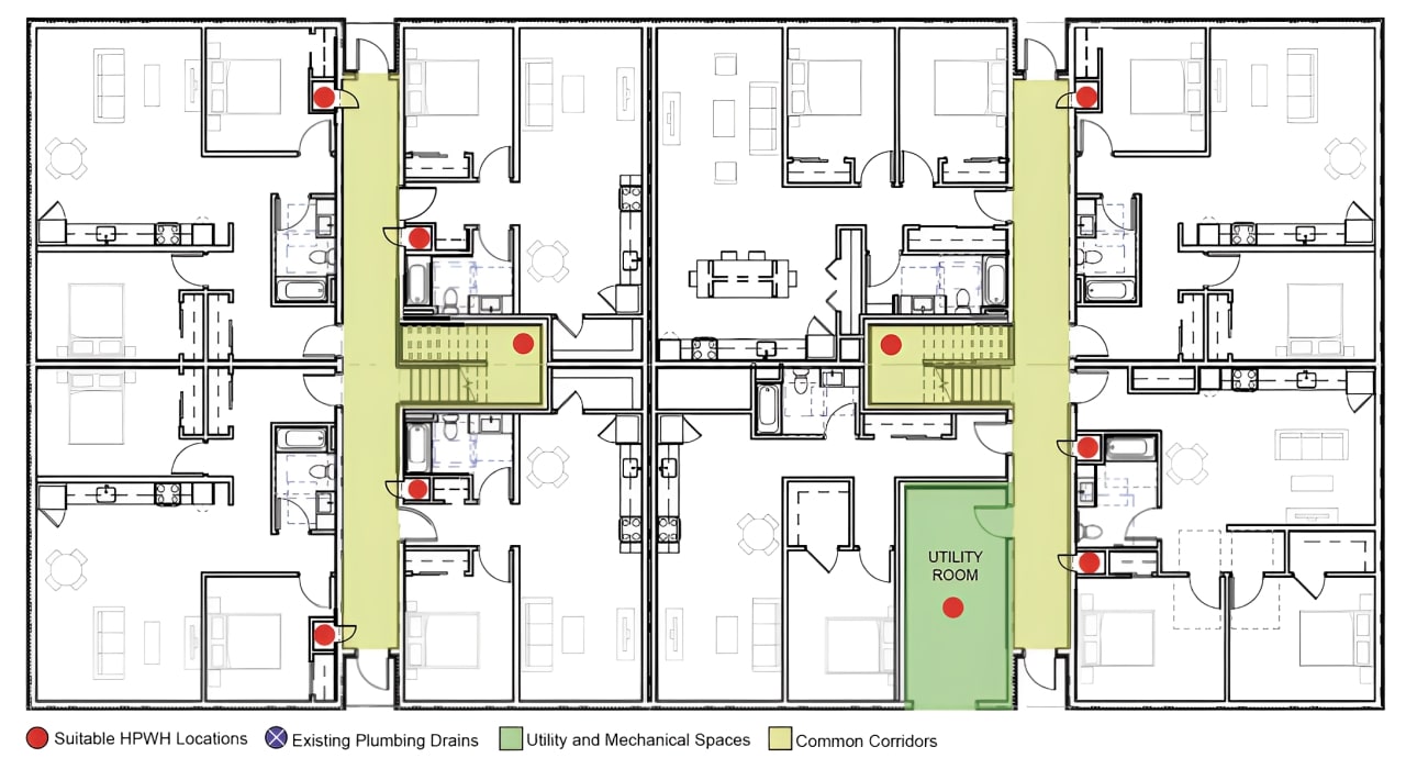
Right – Possible Heat Pump Water Heater Locations on a Multifamily Floorplan including interior corridor closets, under-stair closes, and utility rooms
Image
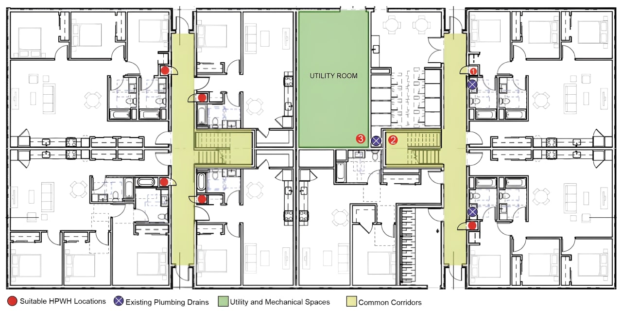
Right – Possible Heat Pump Water Heater Locations on Full Plate Floorplan in a Multifamily Building
Image
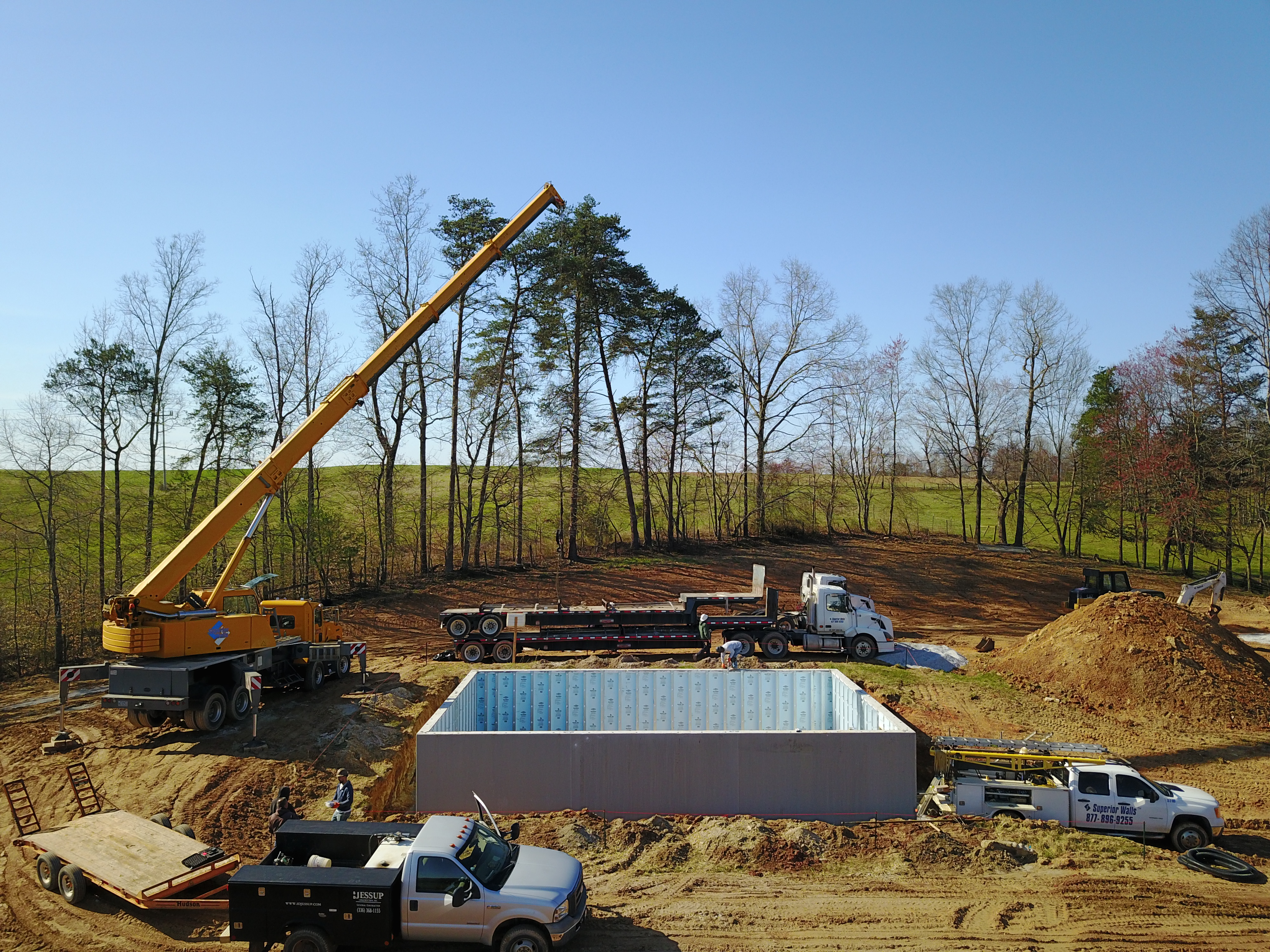
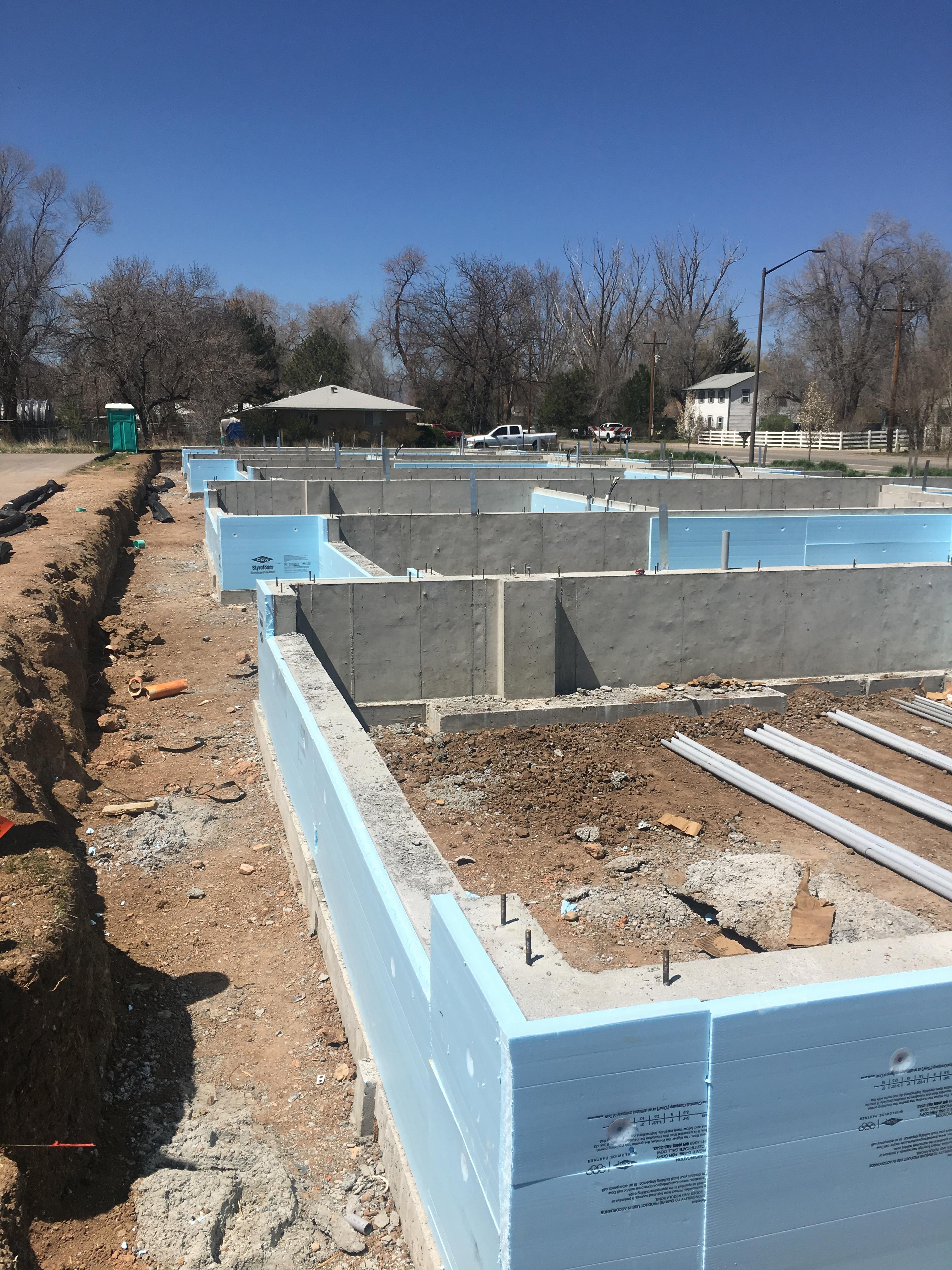
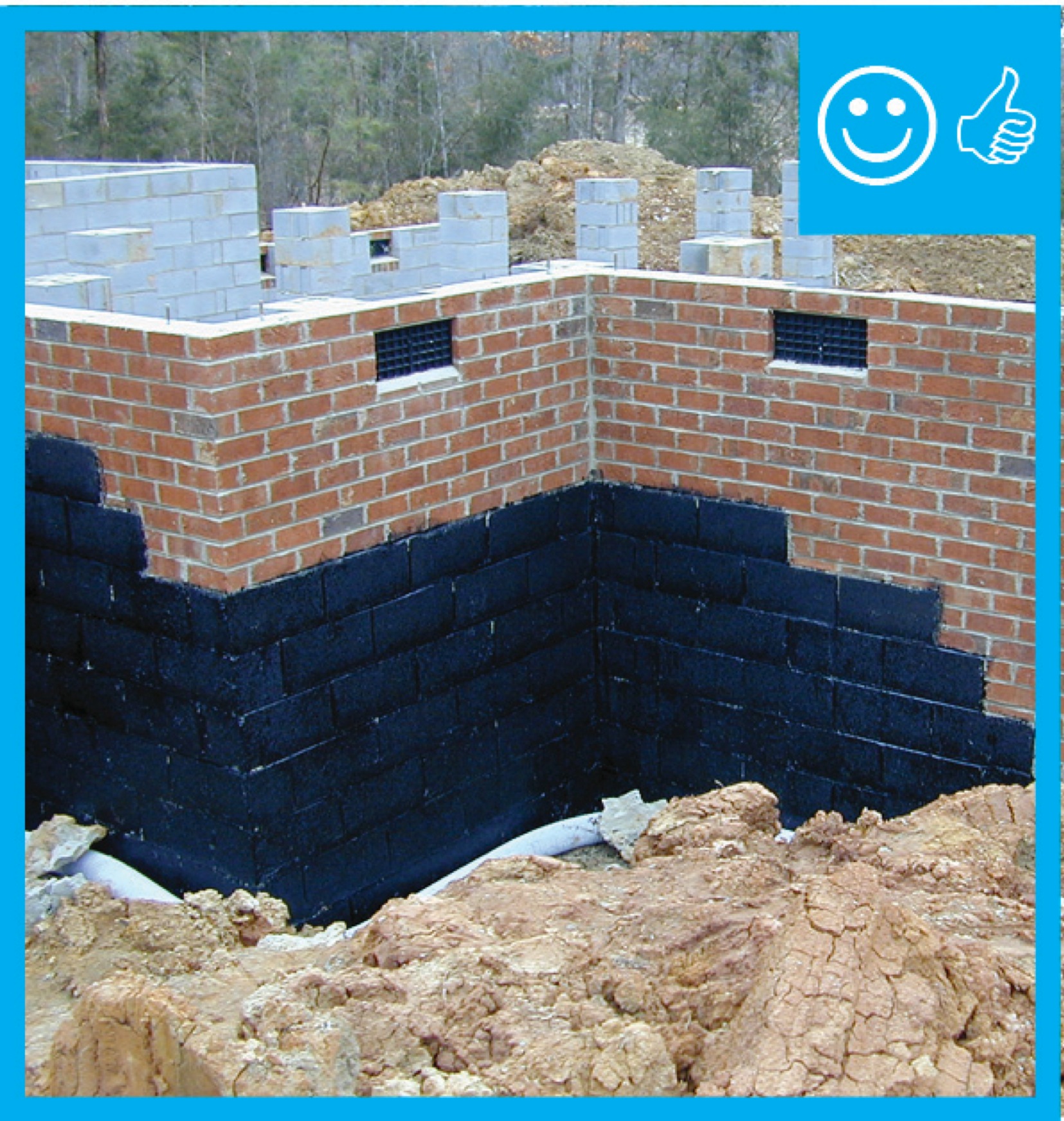
Right – Precast concrete basement walls come to the site with integrated insulation and steel-faced concrete studs.
Image
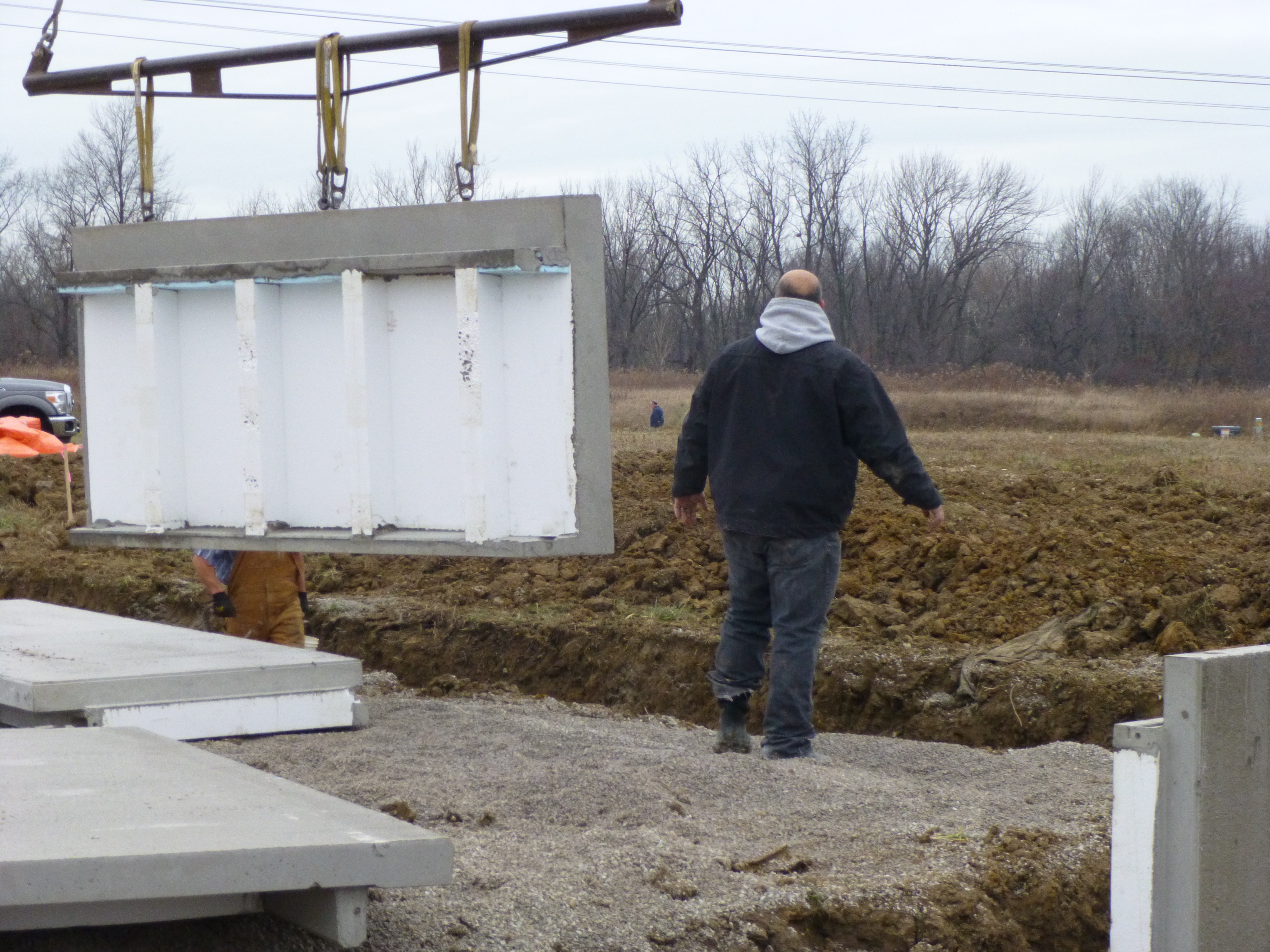
Right – Prepoured foundation panels with integrated insulation and vapor barrier are installed in place.
Image
Image
Image
Image
Image

Image
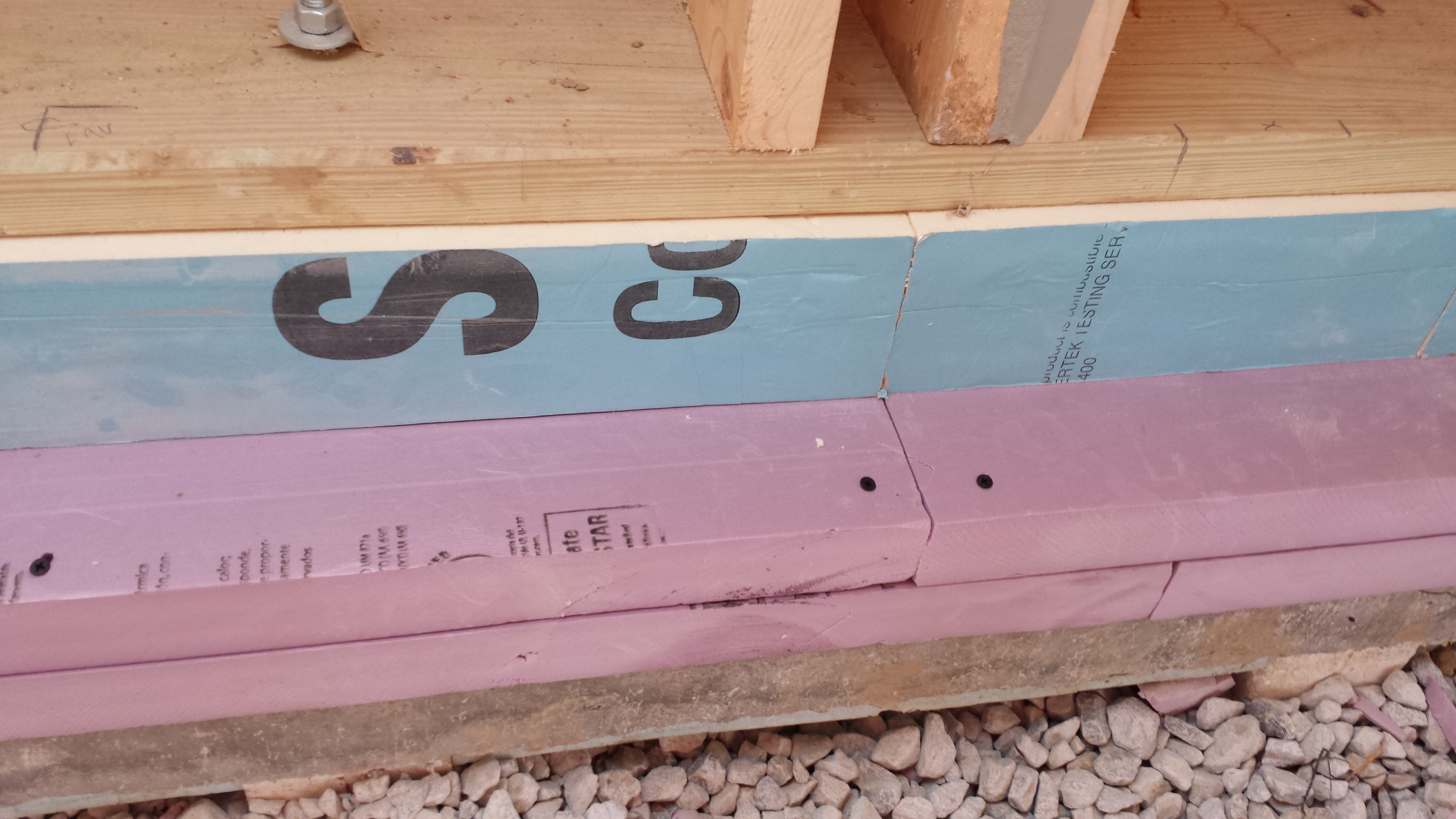
Right – R-20 of XPS and polyiso rigid foam were added on the slab shelf that is part of this precast foundation wall system.
Image
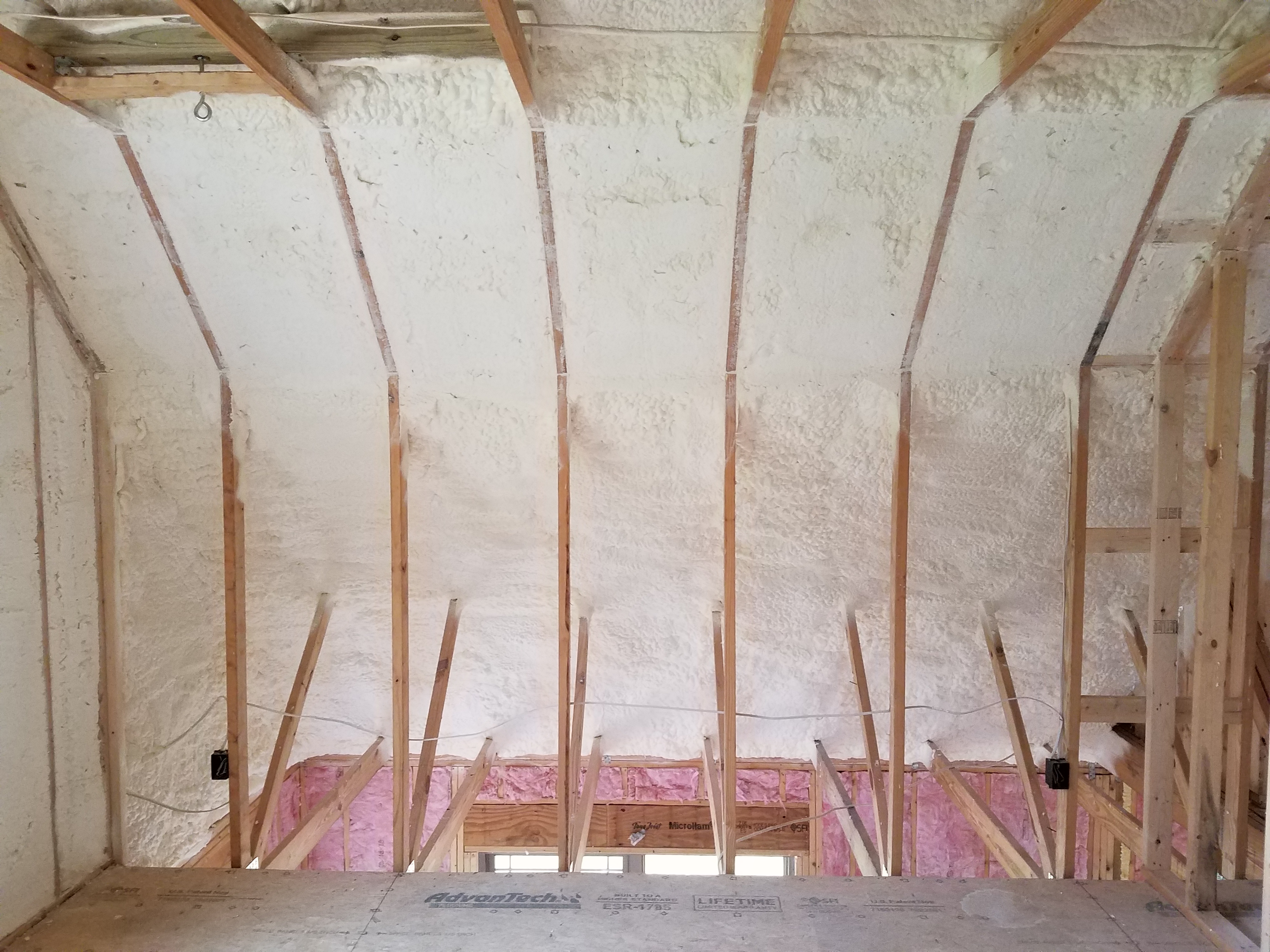
Right – R-23 of blown fiberglass fills the walls and unvented vaulted attic cavities of this marine-climate home while an additional R-20 (4-inches) of graphite-enhanced expanded polystyrene is installed above the roof sheathing.
Image
Right – R-25 of open-cell spray foam lines this new home’s attic ceiling, to protect HVAC ducts from heat and cold.
Image
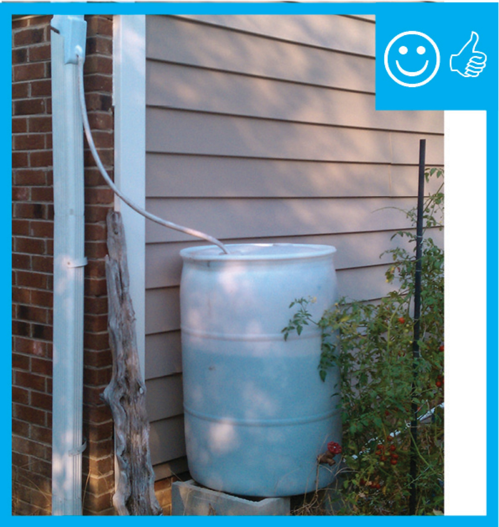
Right – Rain barrel installed with an overflow spout terminating at least 5 feet from foundation
Image
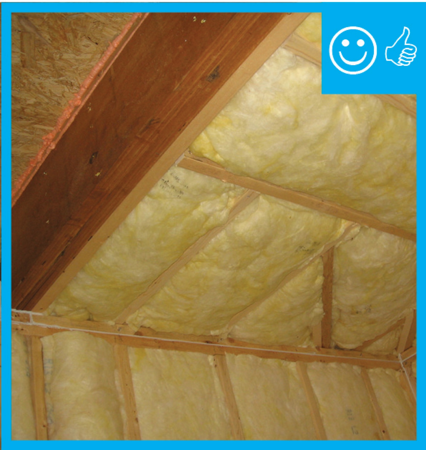
Right – Raised heel trusses allow for full-height insulation over exterior wall top plates.
Image
Right – Raised heel trusses allow room for insulation over the exterior wall top plates, while baffles direct ventilation air to flow above the insulation from the soffit vents to the ridge vents.
Image
Image
Image
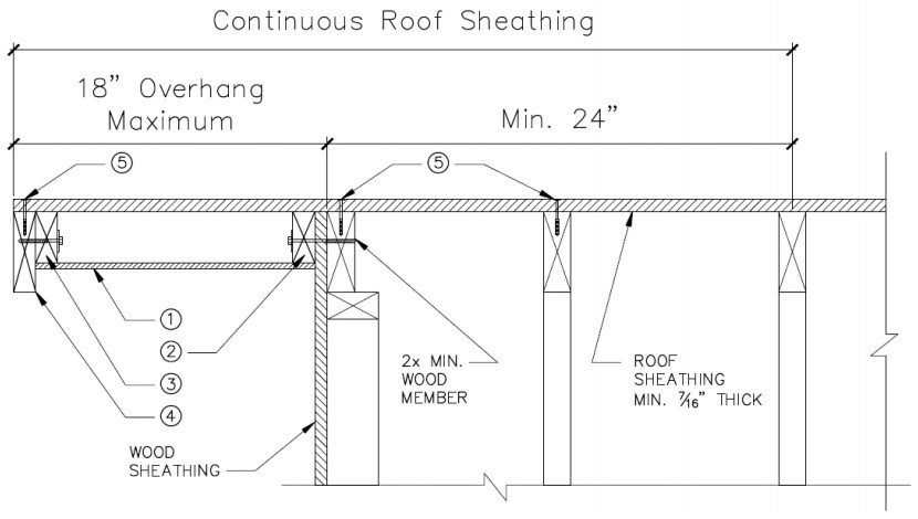
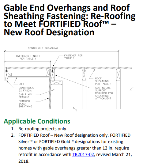
Right – Retrofit Specification for installing roof sheathing an 18-inch gable end overhang
Image
Right – Rigid air barrier installed between double-wall assembly. Inside cavity will be insulated
Image
Image
Image
Image
Image
Image
Image
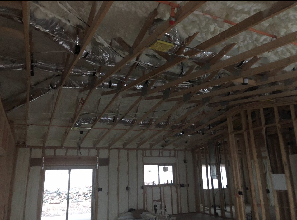
Right – Rigid foam is installed behind HVAC ducts to provide additional insulation to the ducts which are installed within the conditioned space.
Image
Right – Rigid foam was attached to the tops of the precast foundation walls to form an insulated edge for the floor slab.
Image

Image
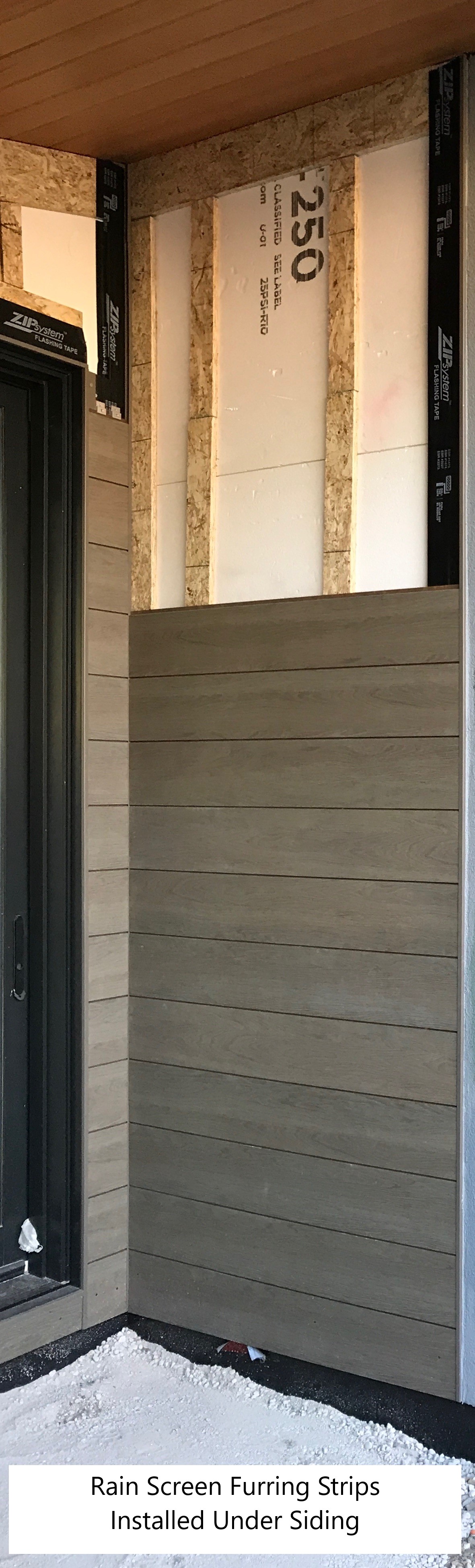
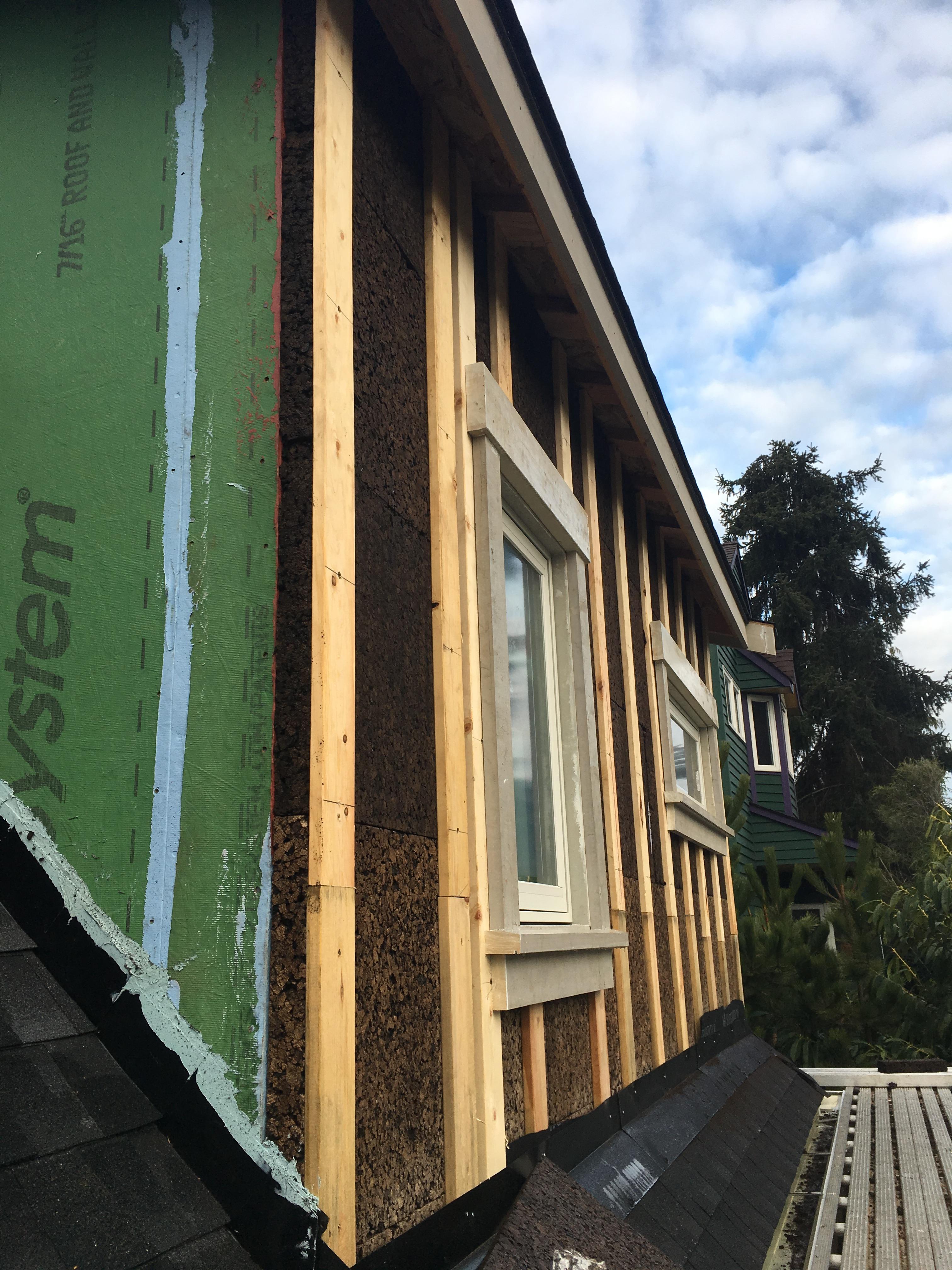
Right – Ripped OSB provides furring strips for a ventilation gap behind the wood siding.
Image
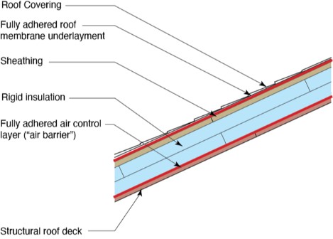
Right – Roof underlayment is fully adhered and roof deck seams are sealed so roof is resistant to high-wind events
Image
Right – Roof underlayment is fully adhered and roof deck seams are sealed so roof is resistant to high-wind events
Image
Image
Image
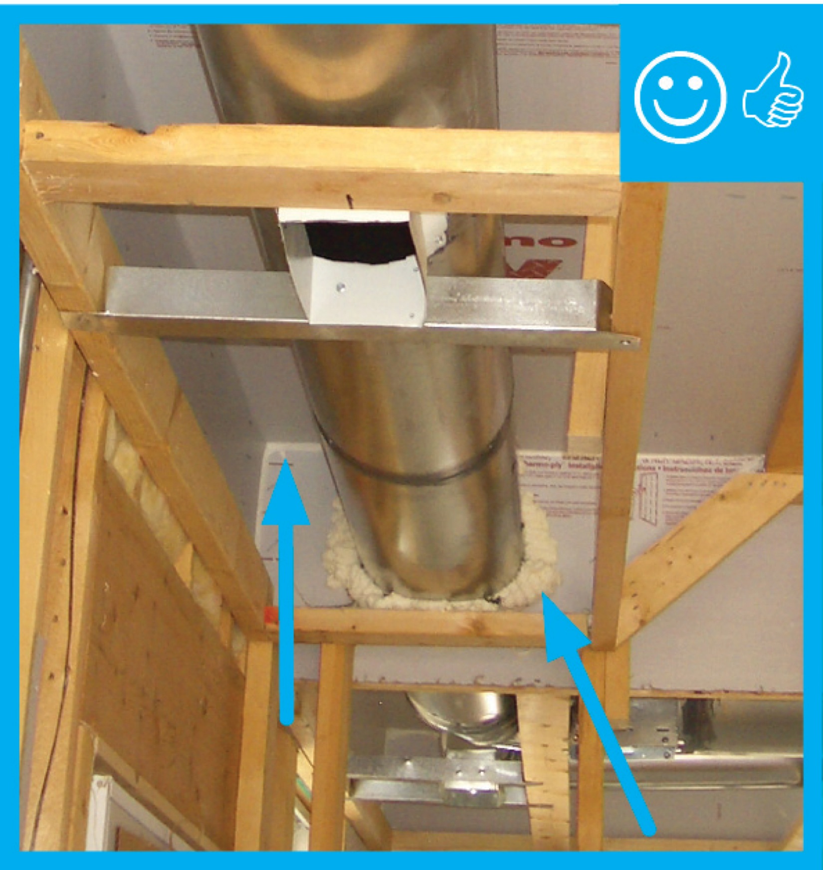
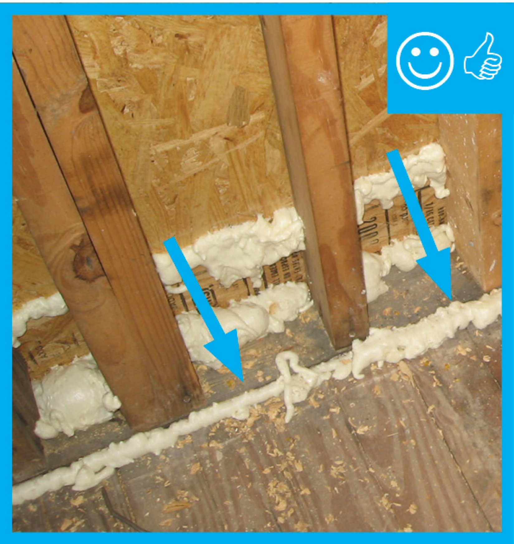
Right – Several potential sources of air leakage into the attic have been air sealed; canned spray foam was used to seal around duct boots, along seams in the drywall, and along top plates.
Image

Right – Sheathing extends to rafters adding strength to soffit, baffles keep attic insulation from vent to maintain air flow
Image

Right – Sheathing, rigid foam, and windows are installed in the factory for these factory-constructed wall panels.
Image
Image
Image
Right – SIP panels assemble quickly on site to provide sturdy walls and a roof that needs few interior supports so there is great flexibility in the layout of interior spaces.
Image
Image

Image
Image
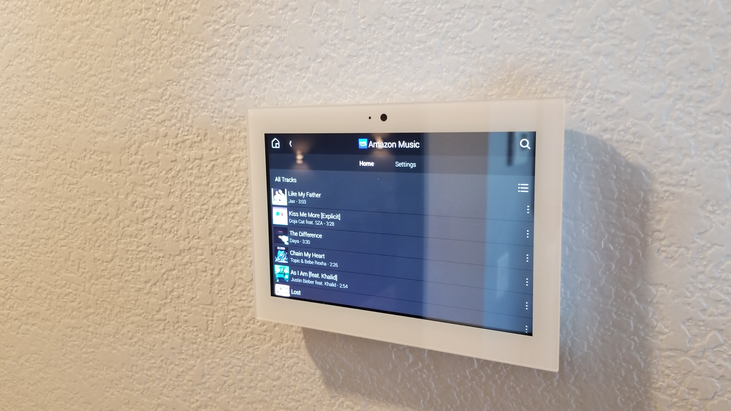
Right – Smart equipment for homes may include a tablet or touchpad from which the homeowner can control lighting, HVAC, window shades, security, music, and other home automation features.
Image
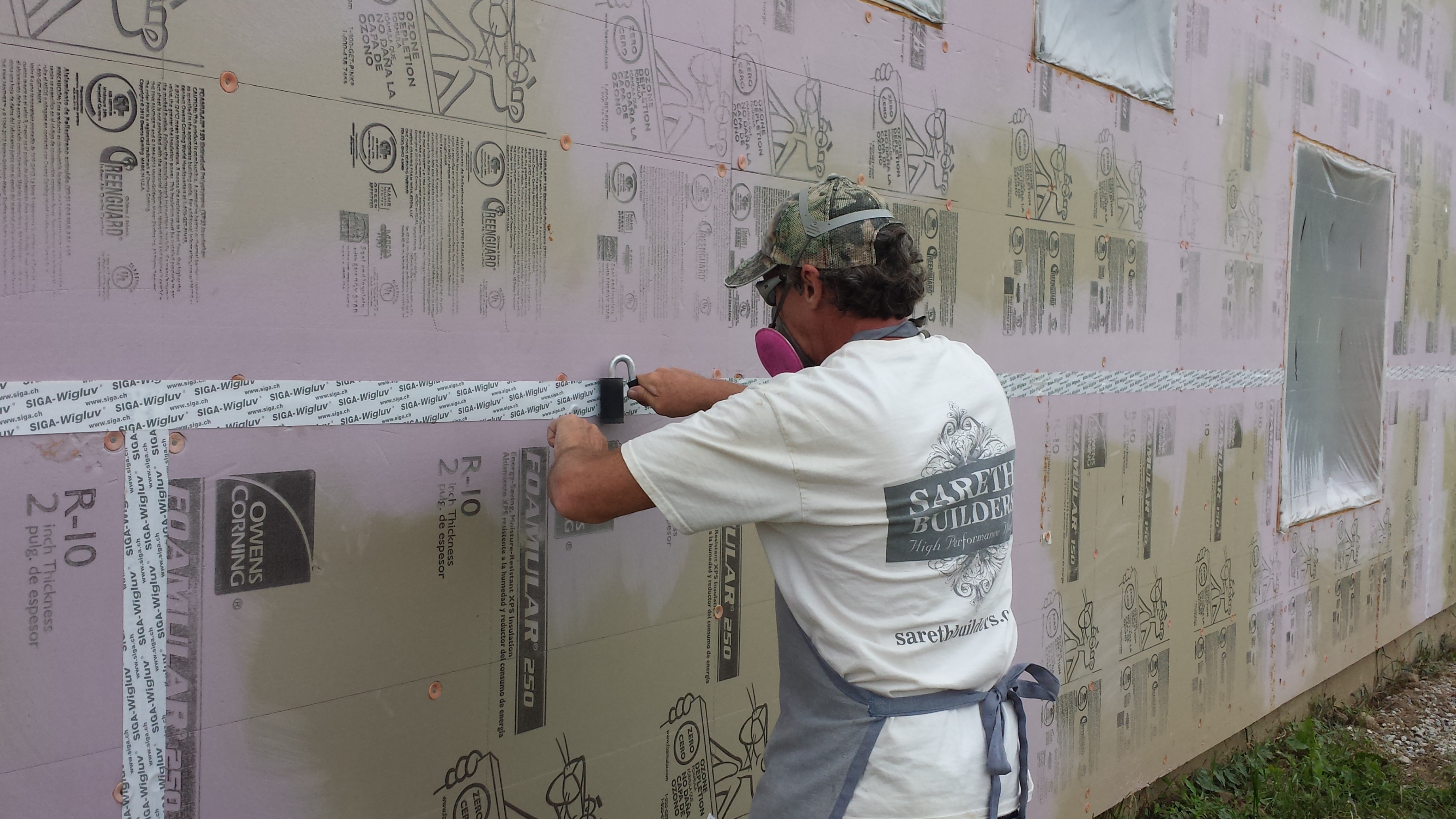
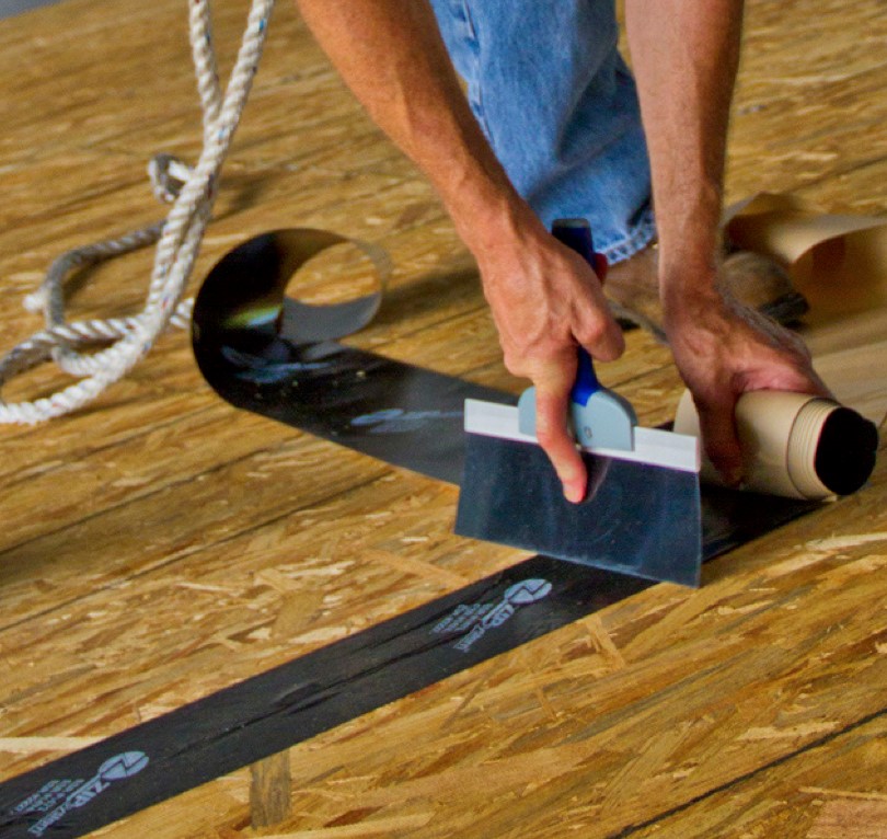
Right – Some tape is pressure sensitive; a roller is used to apply even pressure to ensure full adhesion.
Image
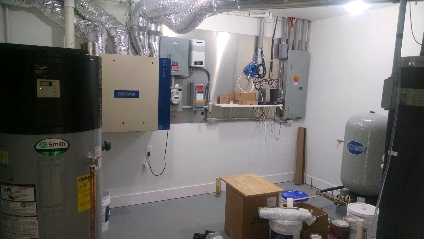
Right – Space was provided next to the electric meter for home’s solar and home energy management tracking electronics.
Image
Right – Spray foam air seals and insulates the walls including the walls behind the fireplace and covers the underside of the roof deck of this mixed-dry climate home to provide an insulated attic space for HVAC ducts.
Image
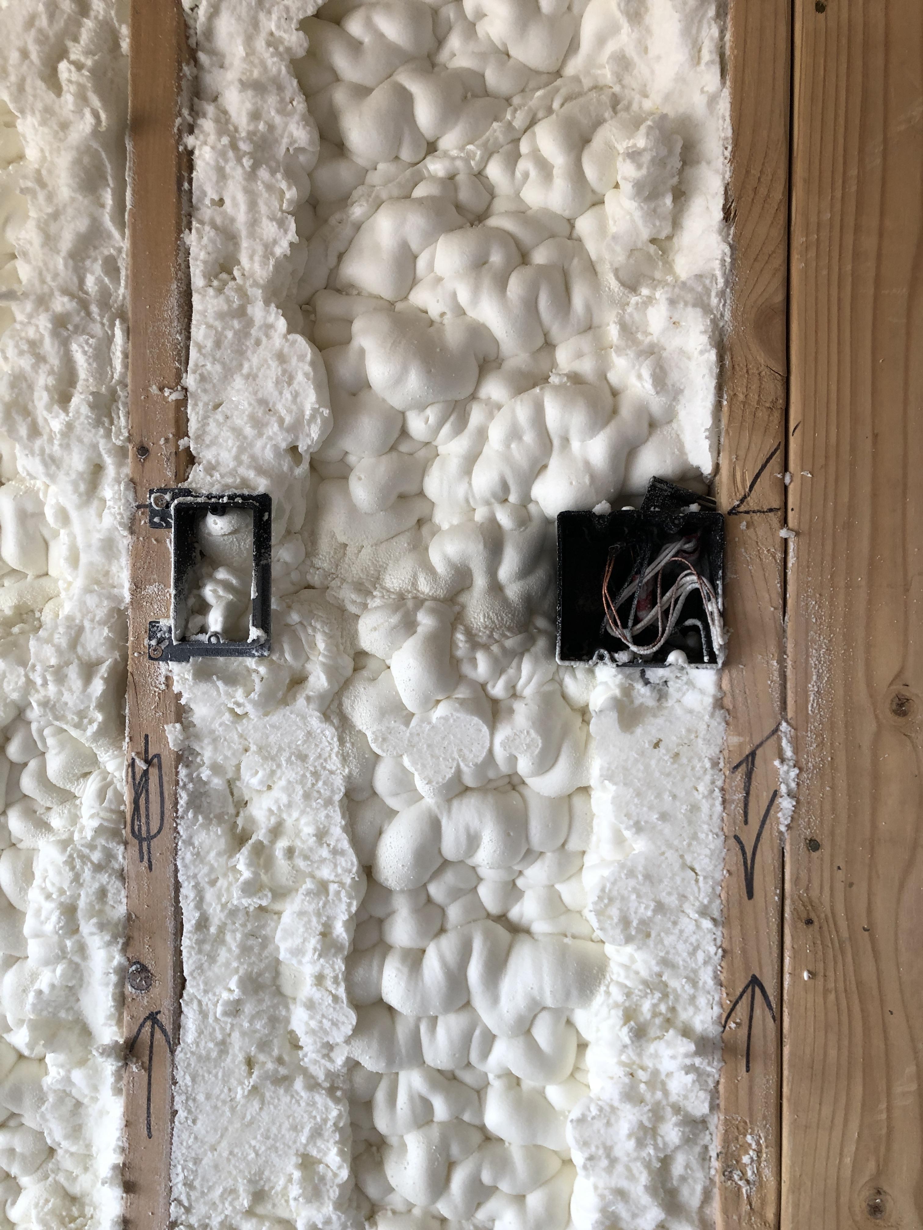
Right – Spray foam completely fills the wall cavities, providing a thorough layer of insulation behind electrical boxes.
Image
Image
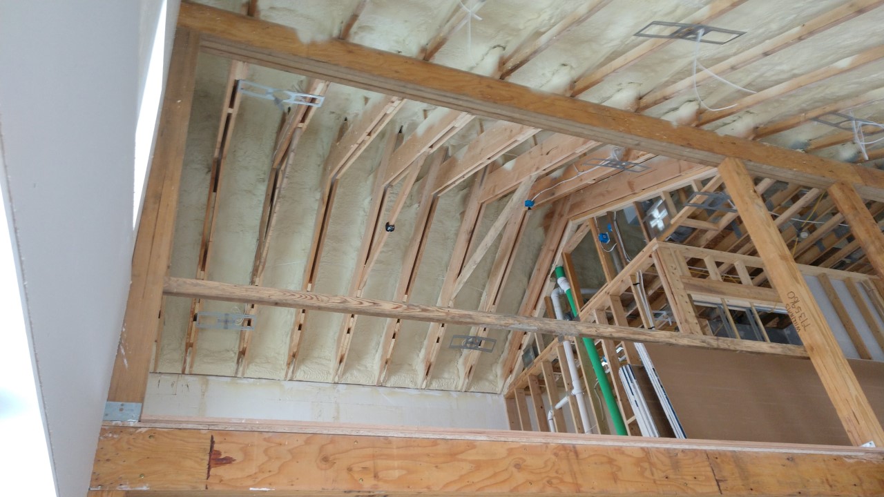
Right – Spray foam fills the roof joist cavities of this vaulted, unvented attic.
Image
Image
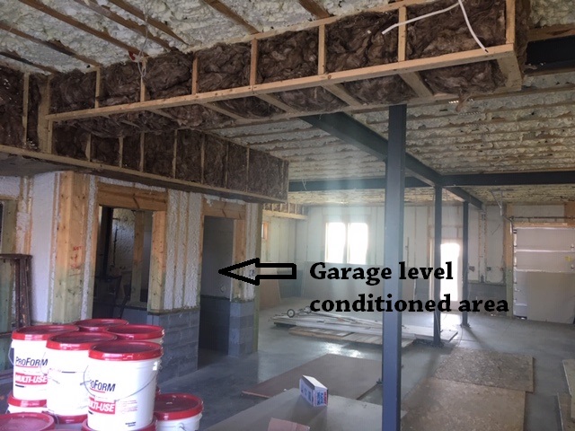
Right – Spray foam insulates the walls and ceilings separating the garage from the home.
Image
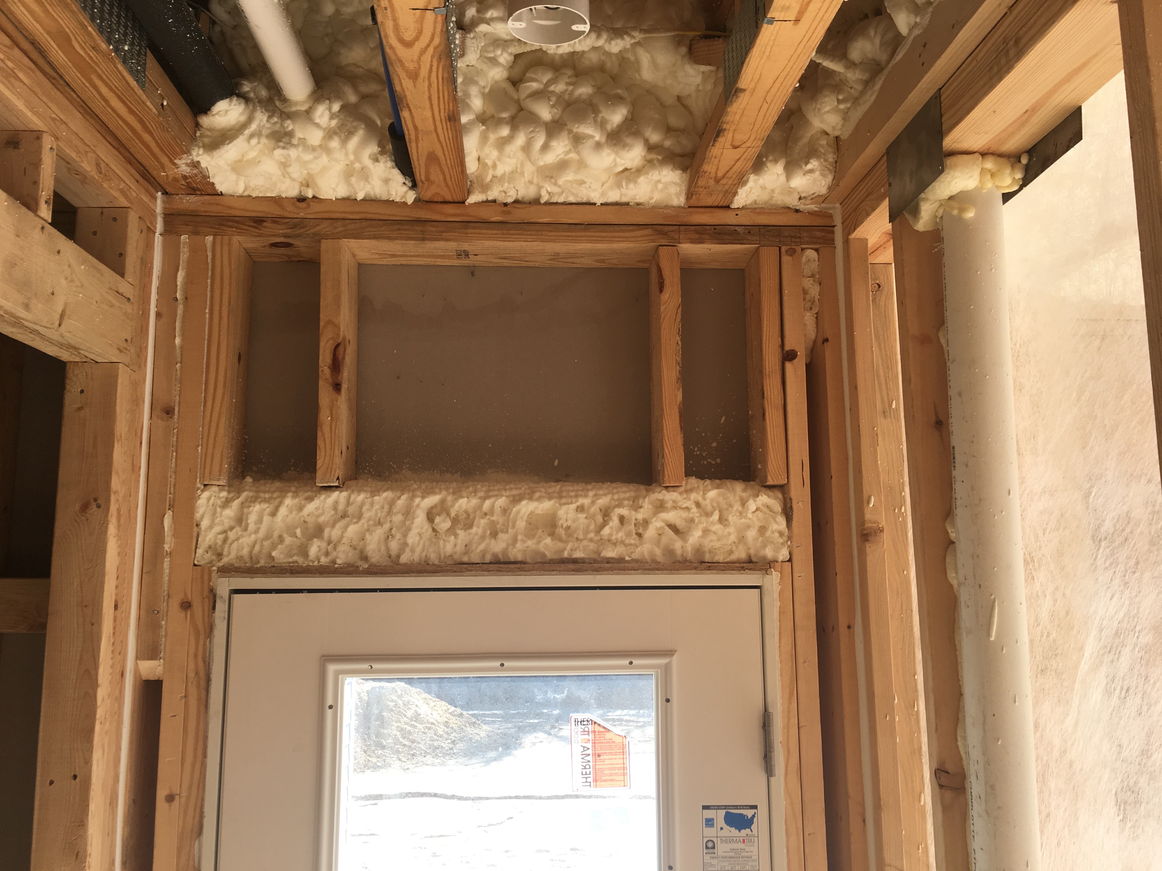
Right – Spray foam insulation fills the header above the door and fills the rim joist between floors.
Image
Right – Spray foam insulation is sprayed on the underside of the roof deck to provide a conditioned space in this low attic for the HVAC ducts.
Image
Right – Spray foam insulation was sprayed onto the ground and along the sides of the foundation walls and piers of this insulated crawl space.
Image
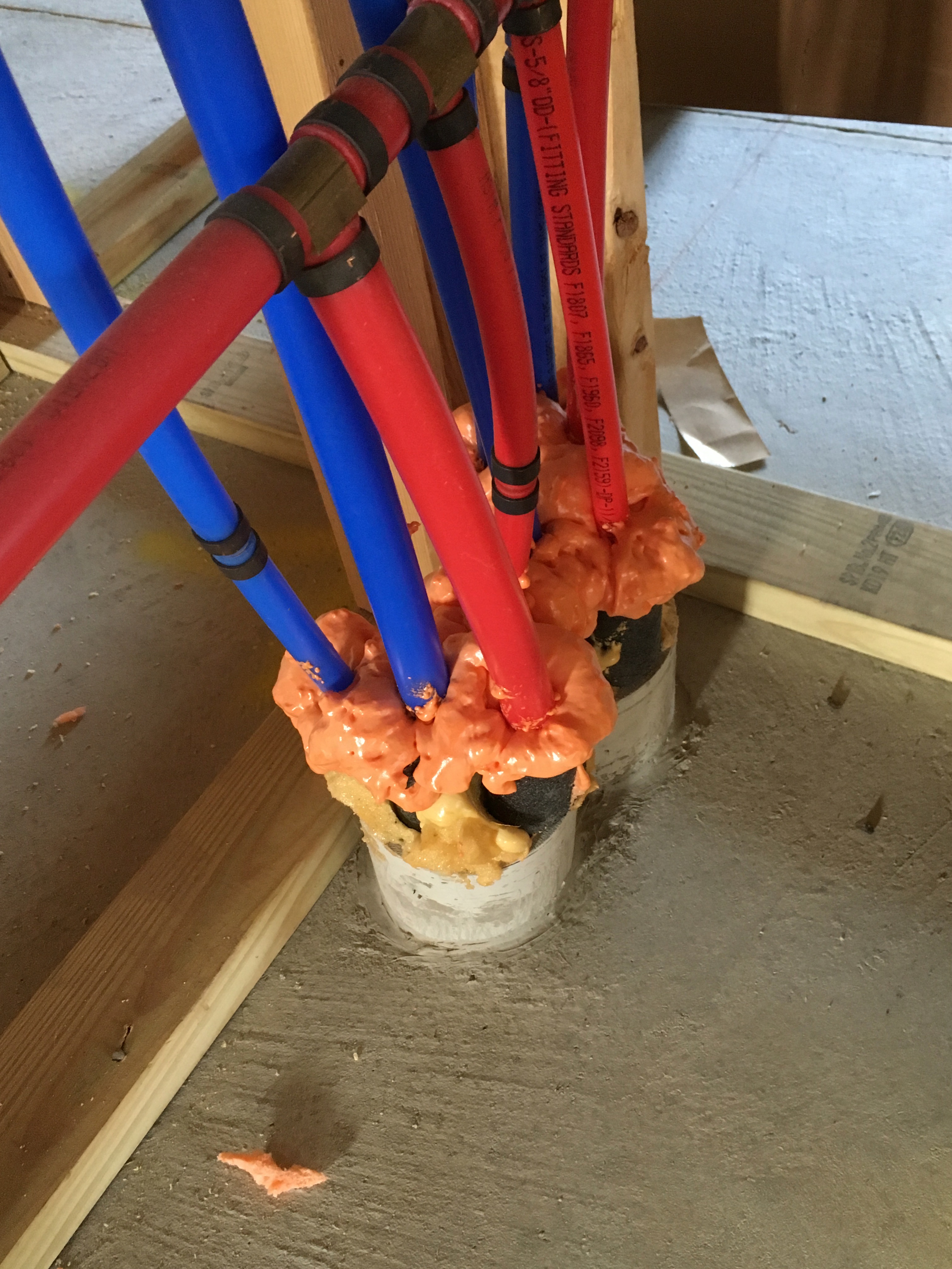
Right – Spray foam is used to carefully seal behind plumbing that was installed in an exterior wall.
Image
Image
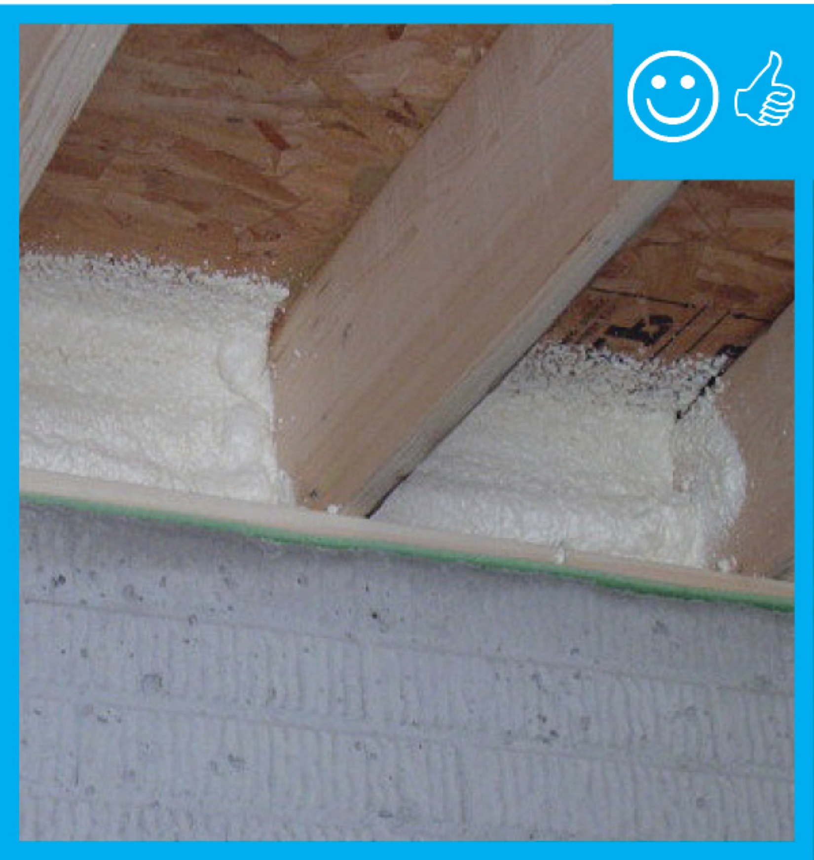
Right – Spray foam was installed at the sheathing intersection as well as the sill plate to sub-floor connection.
Image

Right – Staggered 2x4s are placed every 12 inches on 2x6 plates, providing a nailing surface on each side of the wall every 24 inches.
Image
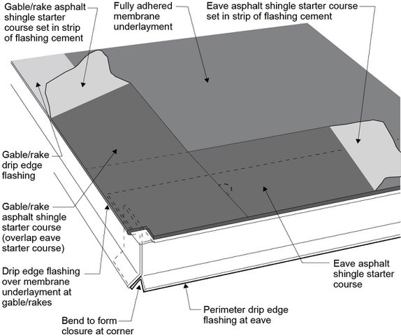
Right – Start asphalt shingle installation with a starter strip set in an 8-inch strip of flashing cement
Image
Right – Strategically placed trees provide shade to the south-facing windows of this building.
Image
Image

Image
Right – Structural insulated panels are quickly assembled on site for this SIP house.
Image
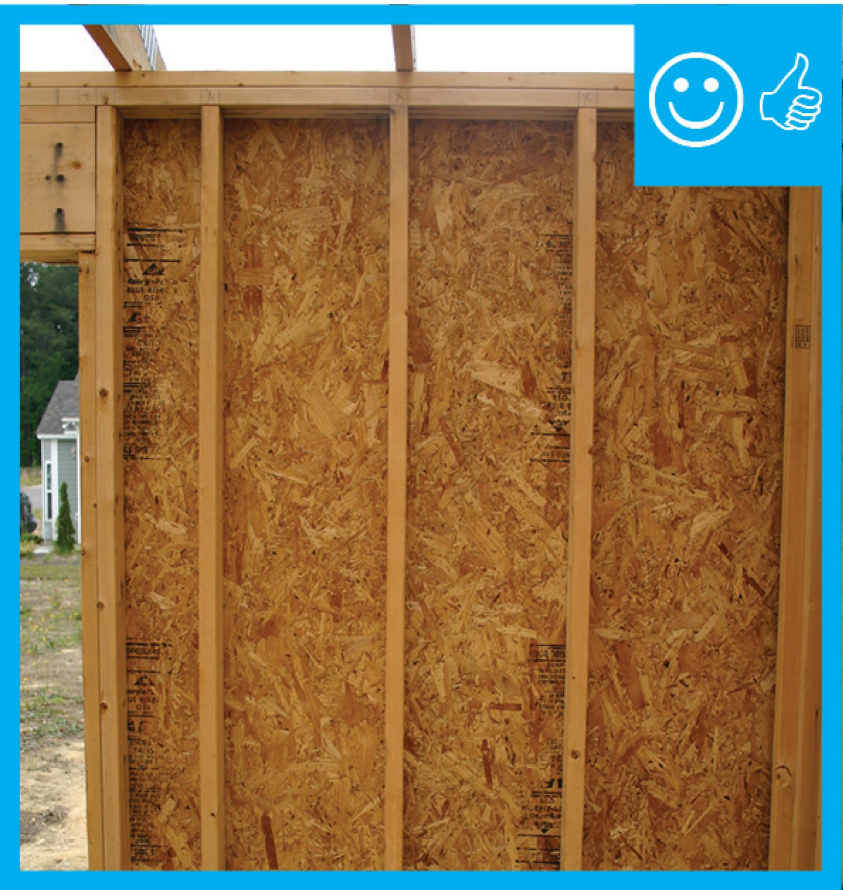
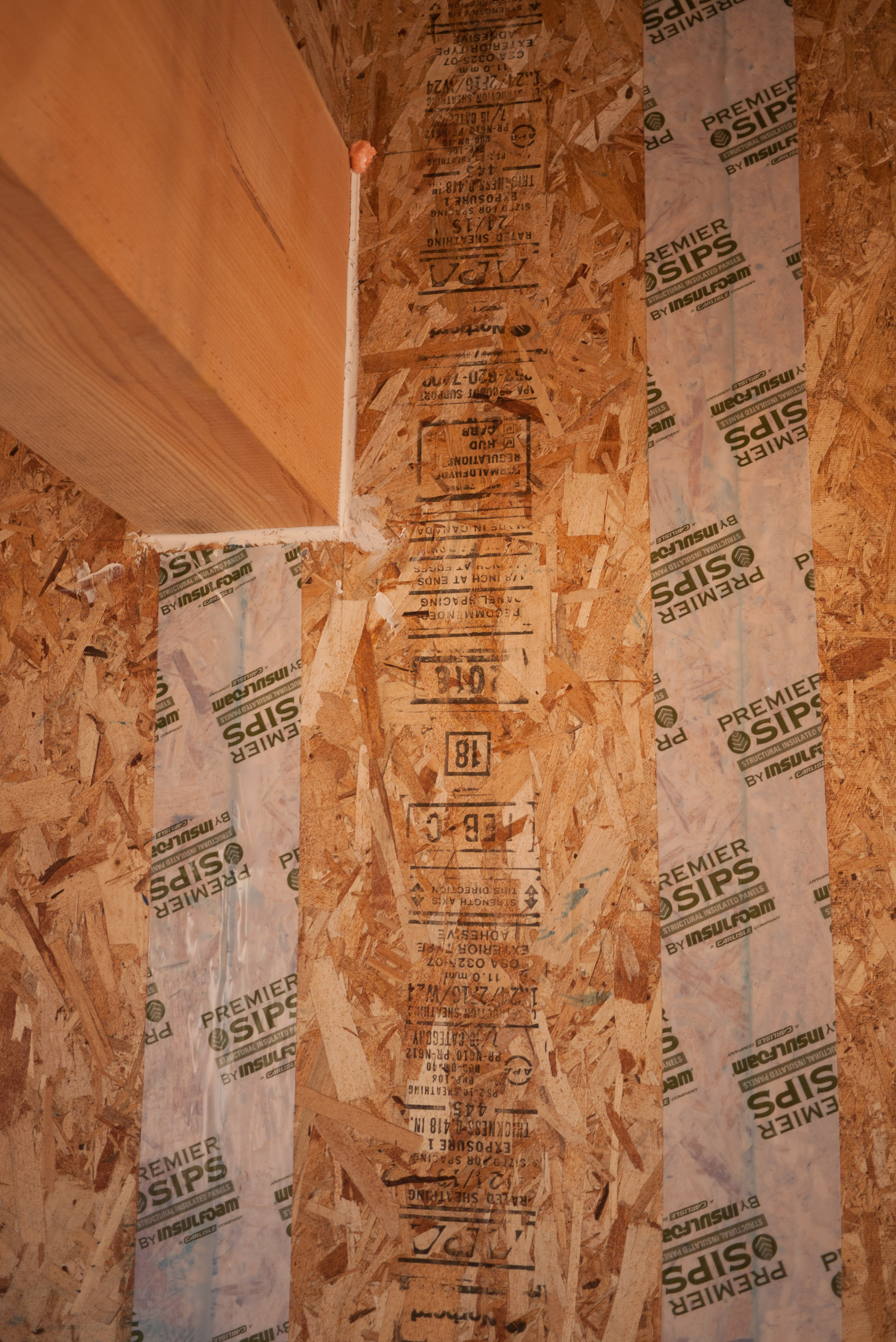
Right – Structural insulated sheathing can provide racking strength (lateral load resistance), and serve as an air barrier and thermal barrier if installed according to manufacturer’s specifications with taped, sealed seams
Image
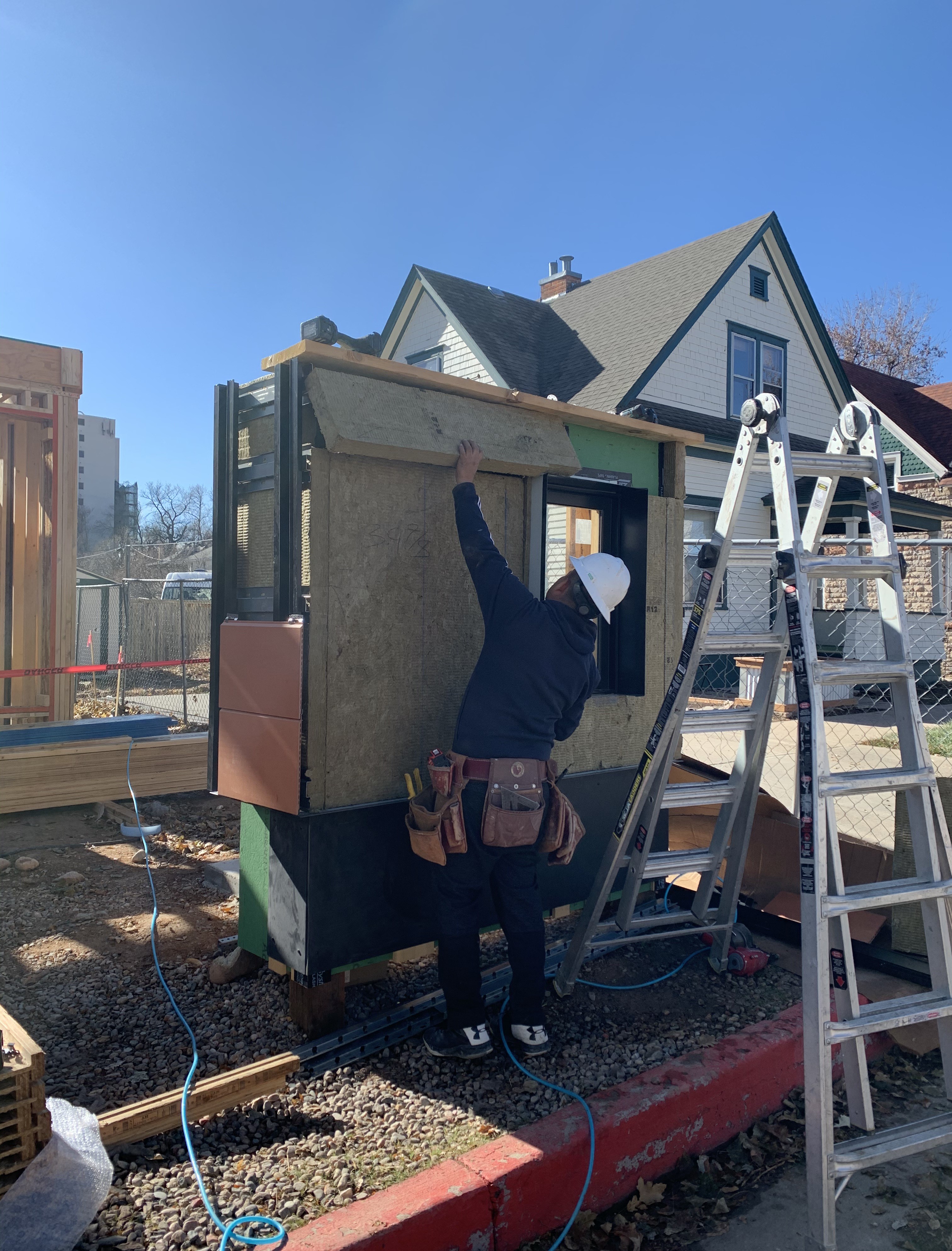
Right – Subfloors are installed in a clean, dry, well-lit factory setting for these modular, factory-built homes.
Image

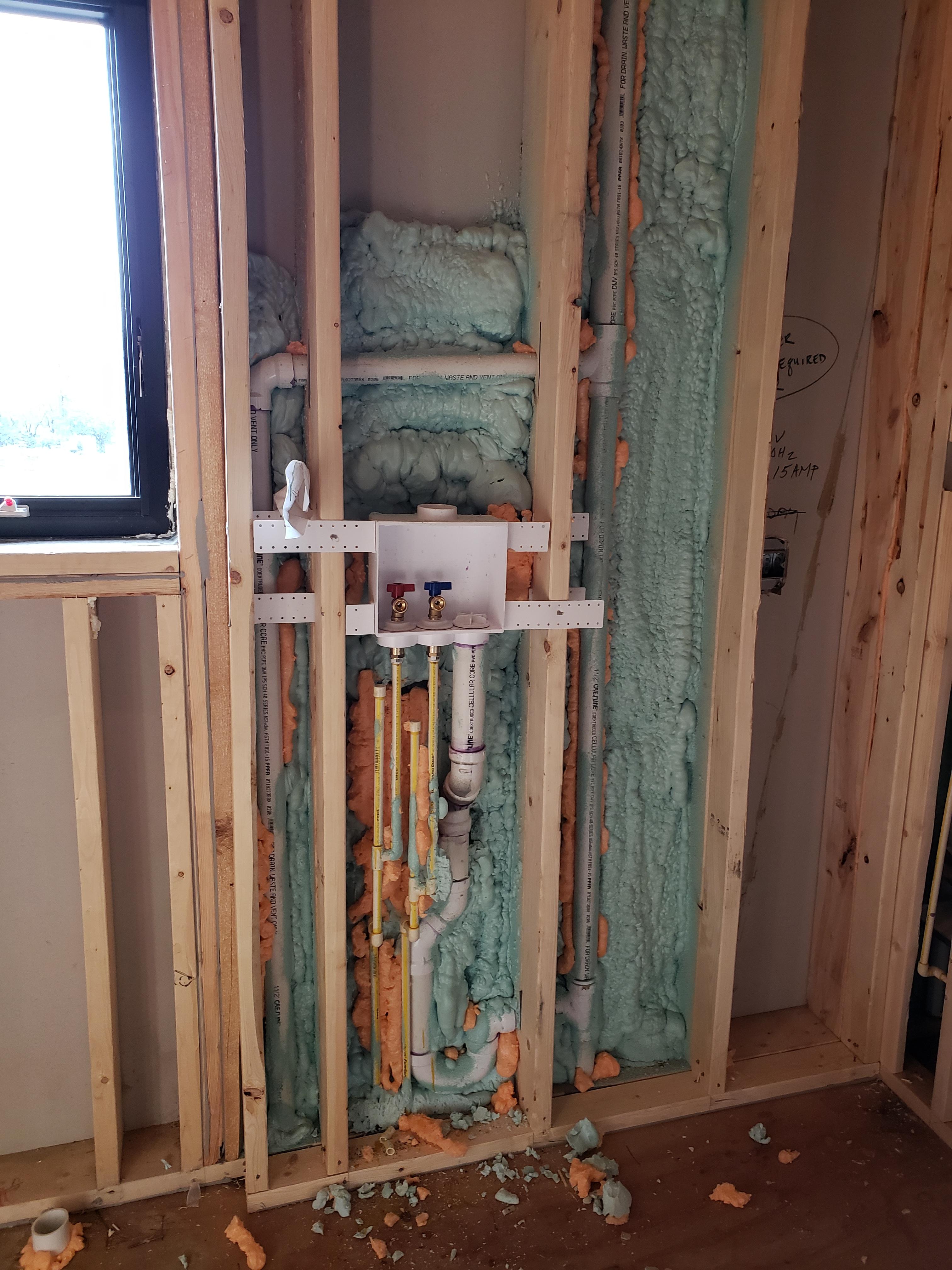
Right – Tape and spray foam are used to air seal around pipes that extend through exterior walls.
Image
Image
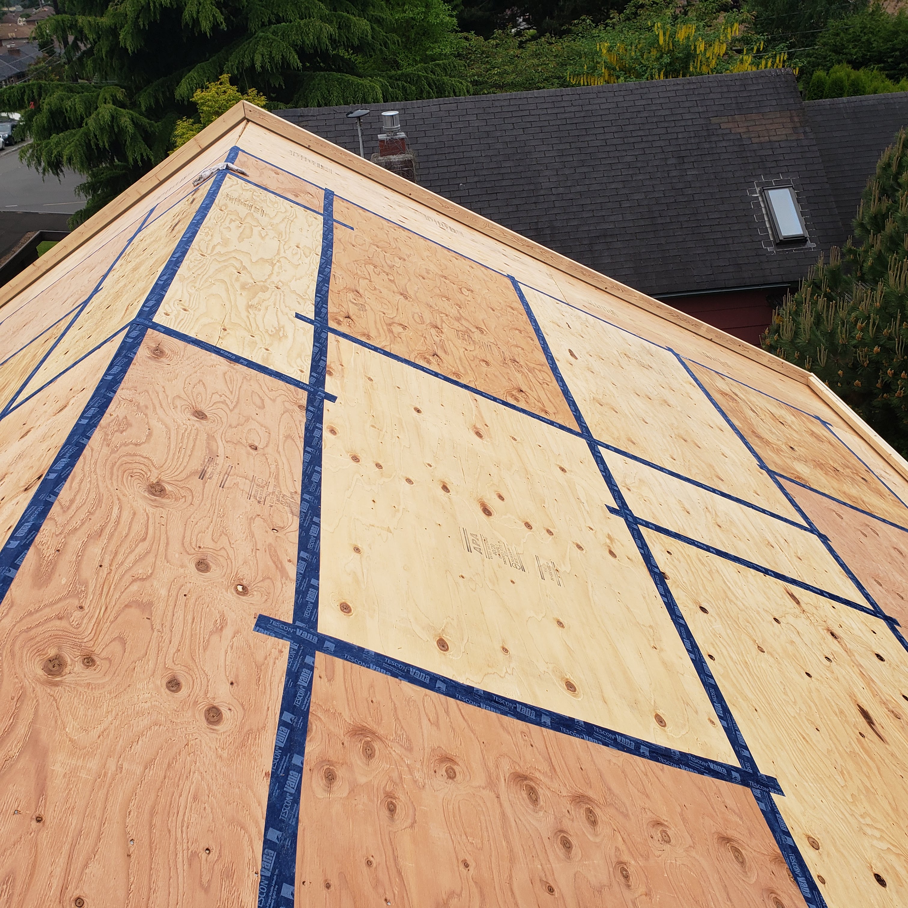
Right – Taping the roof sheathing seams can greatly decrease the likelihood of water infiltration into a home in the event of a hurricane.
Image

Right – Terra cotta tiles are attached to horizontal metal furring strips as the exterior cladding over mineral wool insulation on this multi-family building in Colorado.
Image
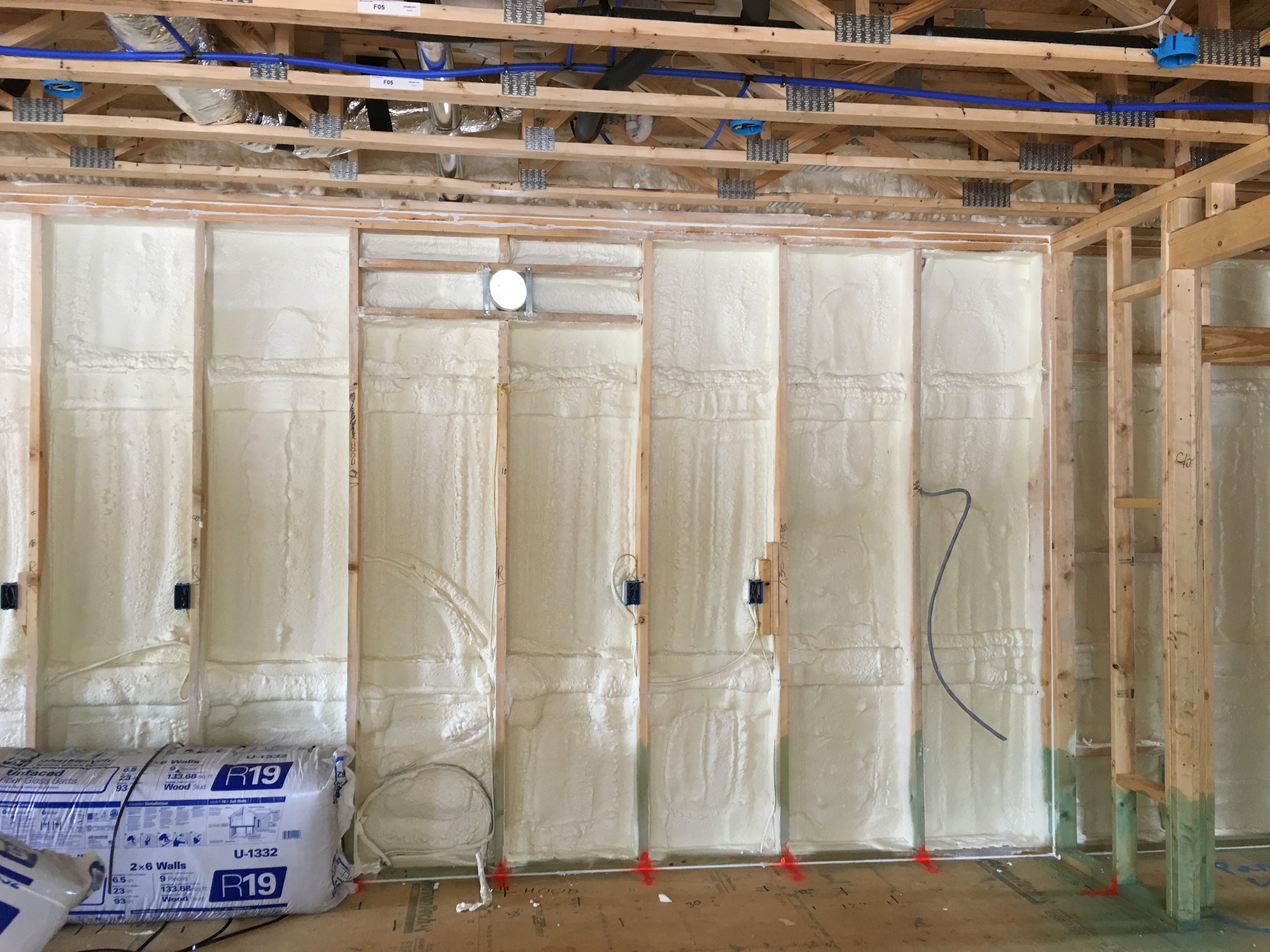
Right – the 2x6 walls are insulated with a flash-and-batt approach that includes spraying the wall cavities with one inch of open-cell foam to seal the sheathing to the framing then filling the wall cavities with R-19 fiberglass batts that are compressed
Image
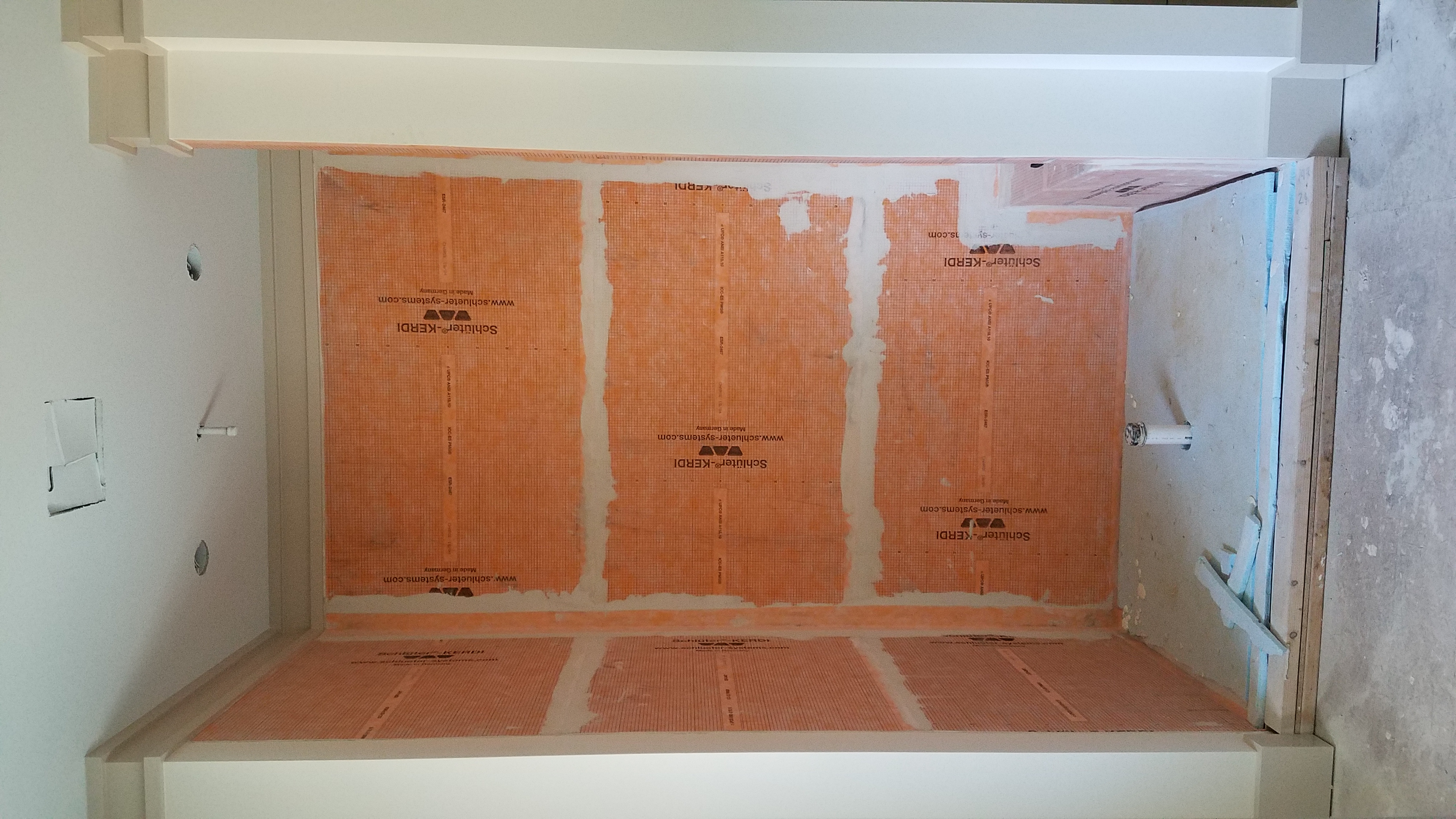
Right – The air- and water-barrier material lining the shower stall is mastic sealed to prevent leakage and rigid foam insulation is installed on the floor of the shower.
Image
Image
Image
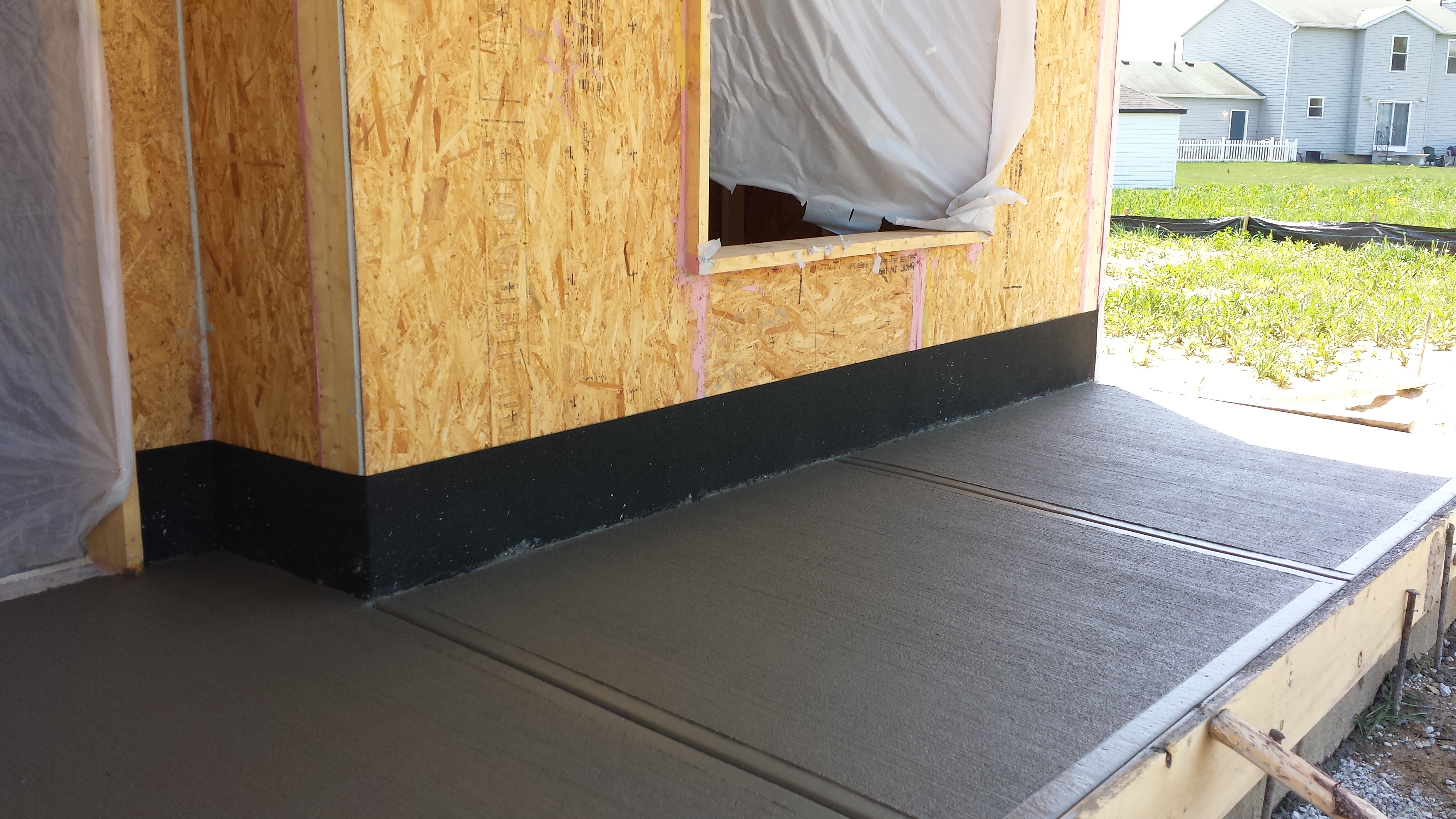
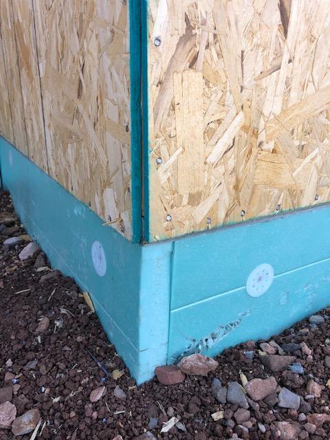
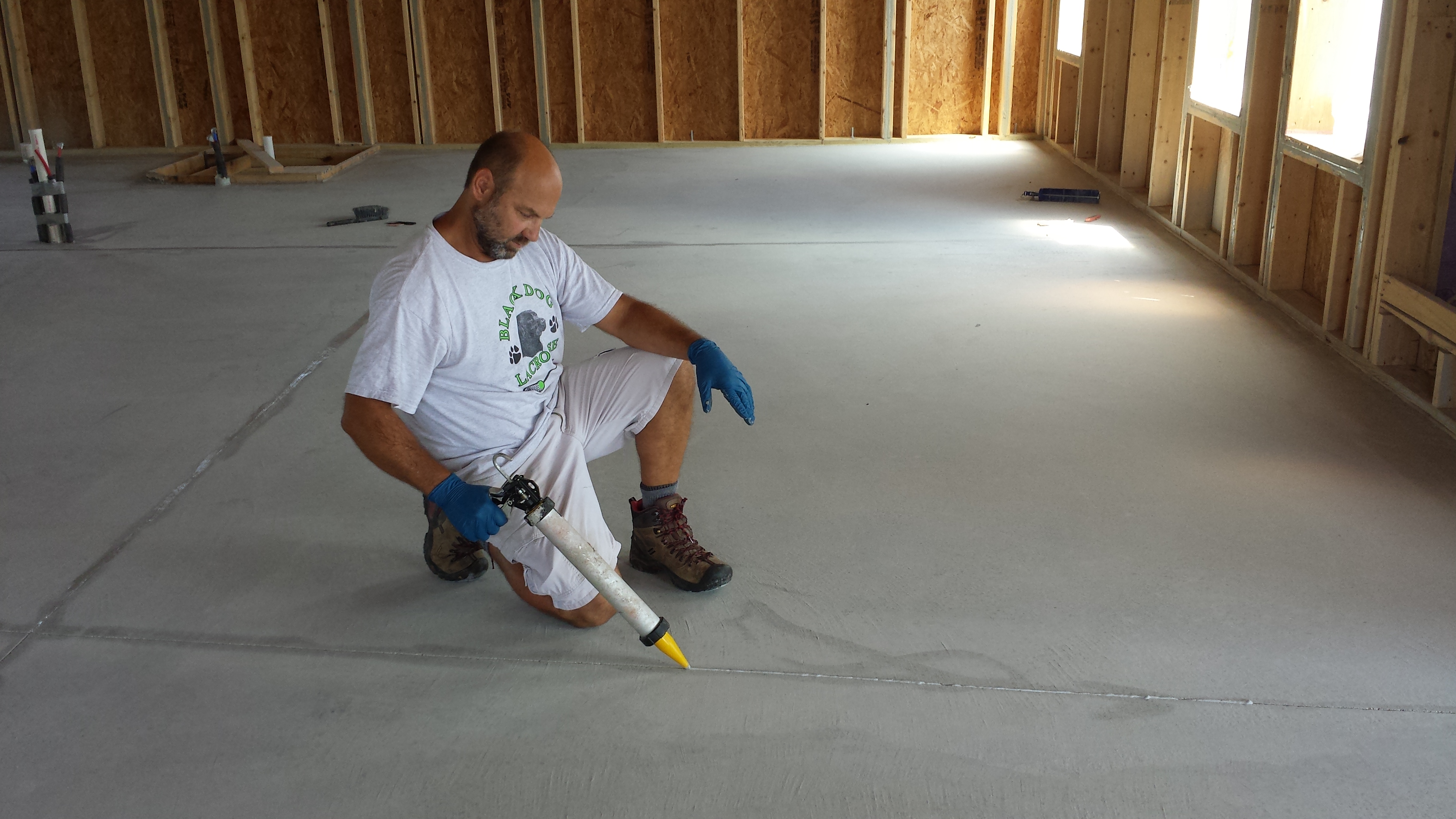
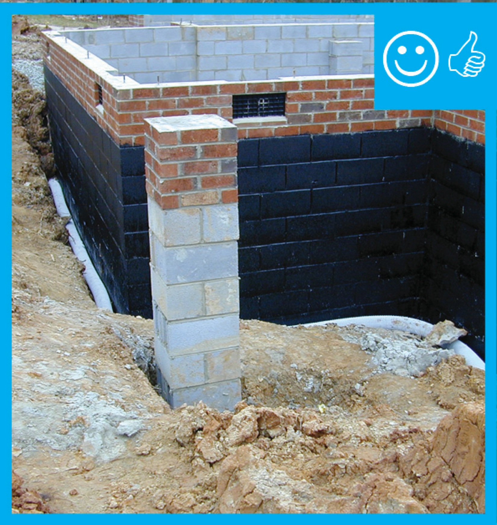
Right – The base of the wall is water proofed and the seam between the base of the wall and the sidewalk is air sealed.
Image
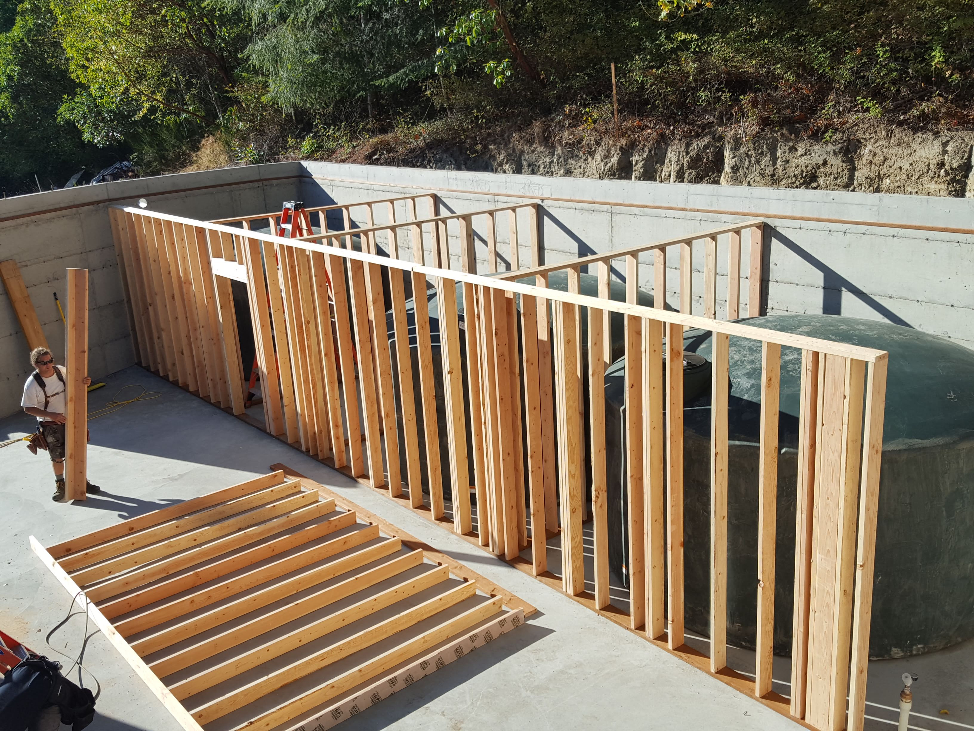
Right – The basement contains four 5,000-gallon rainwater holding tanks for this home which meets all of its water needs with rainwater.
Image
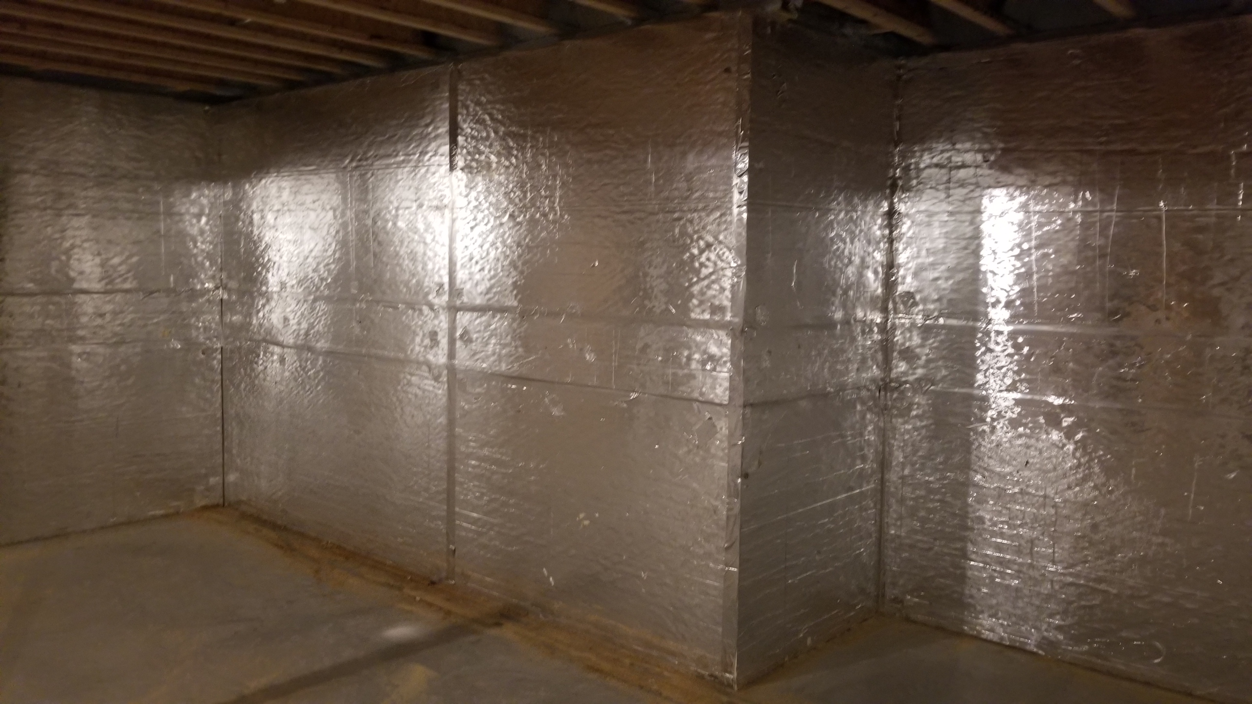
Right – The basement of this cold-climate home is insulated along interior walls with 2 inches of foil-faced rigid foam; finished basement walls also have a 2x4 interior wall insulated with R-19 blown-in fiberglass insulation and a poly vapor barrier.
Image
Image
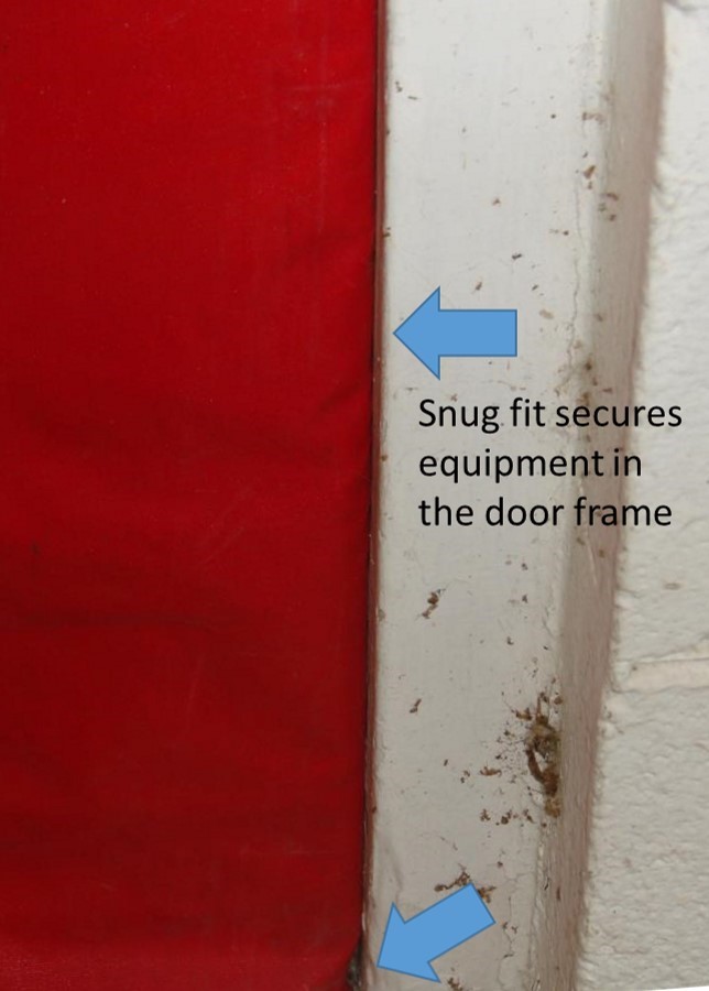
Right – The blower door is installed snugly and securely to the door frame during testing
Image
Right – The blower door pressure reference hose is placed well away from the outdoor side of the fan
Image
Right – The builder constructed a mock up of the wall assembly for this multi-family building.
Image
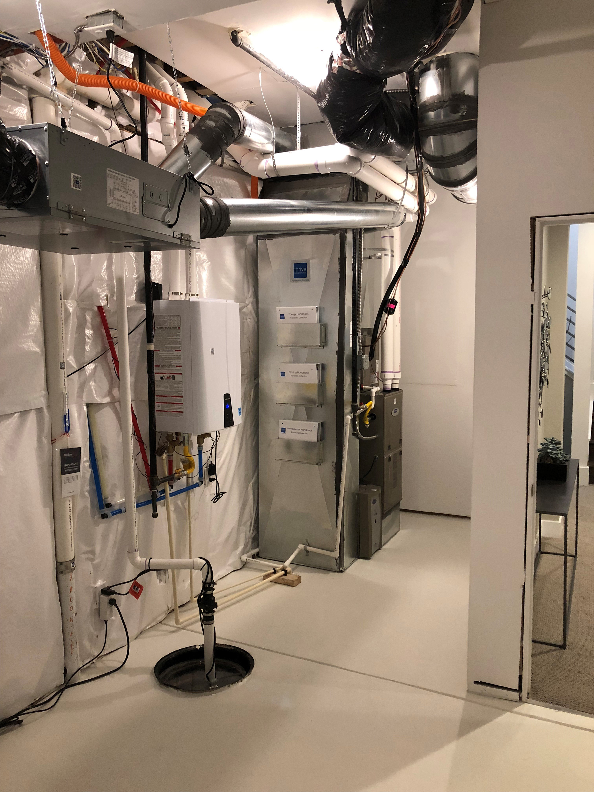
Right – The builder has provided homeowners manuals and racks to hold them on the side of the HVAC cabinet in the utility room.
Image
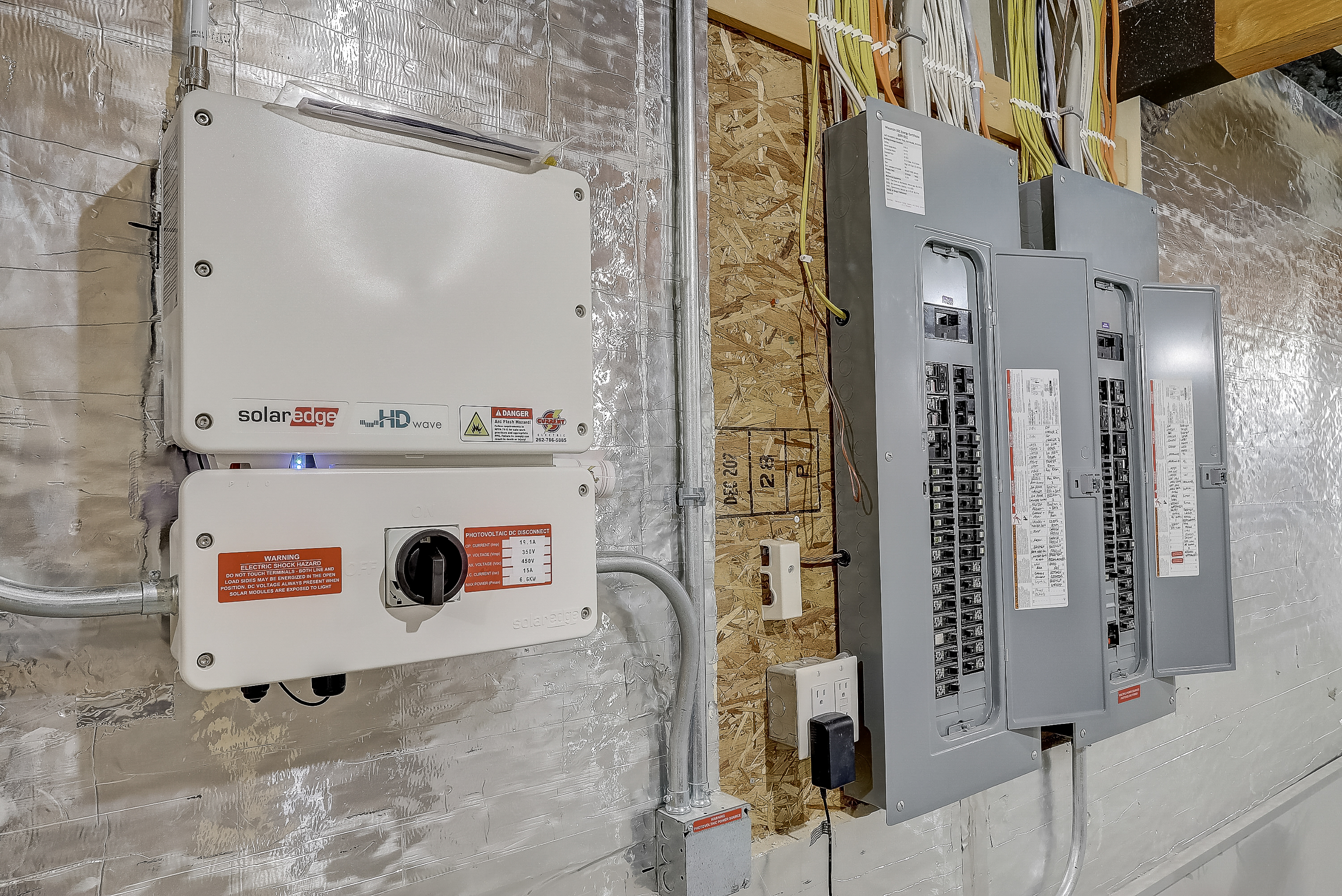
Right – The builder provided adequate wall space for the solar inverter next to the home’s electric panels.
Image
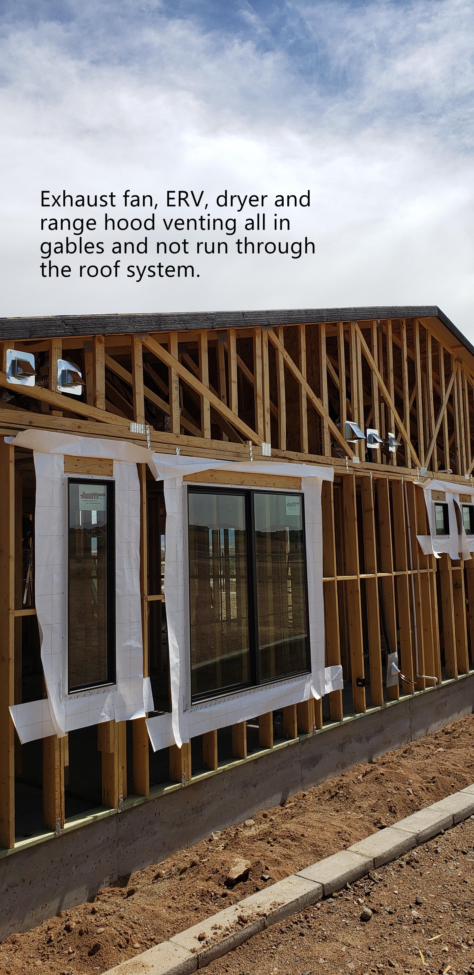
Right – The builder routed all vents through side walls to avoid holes in the roof.
Image
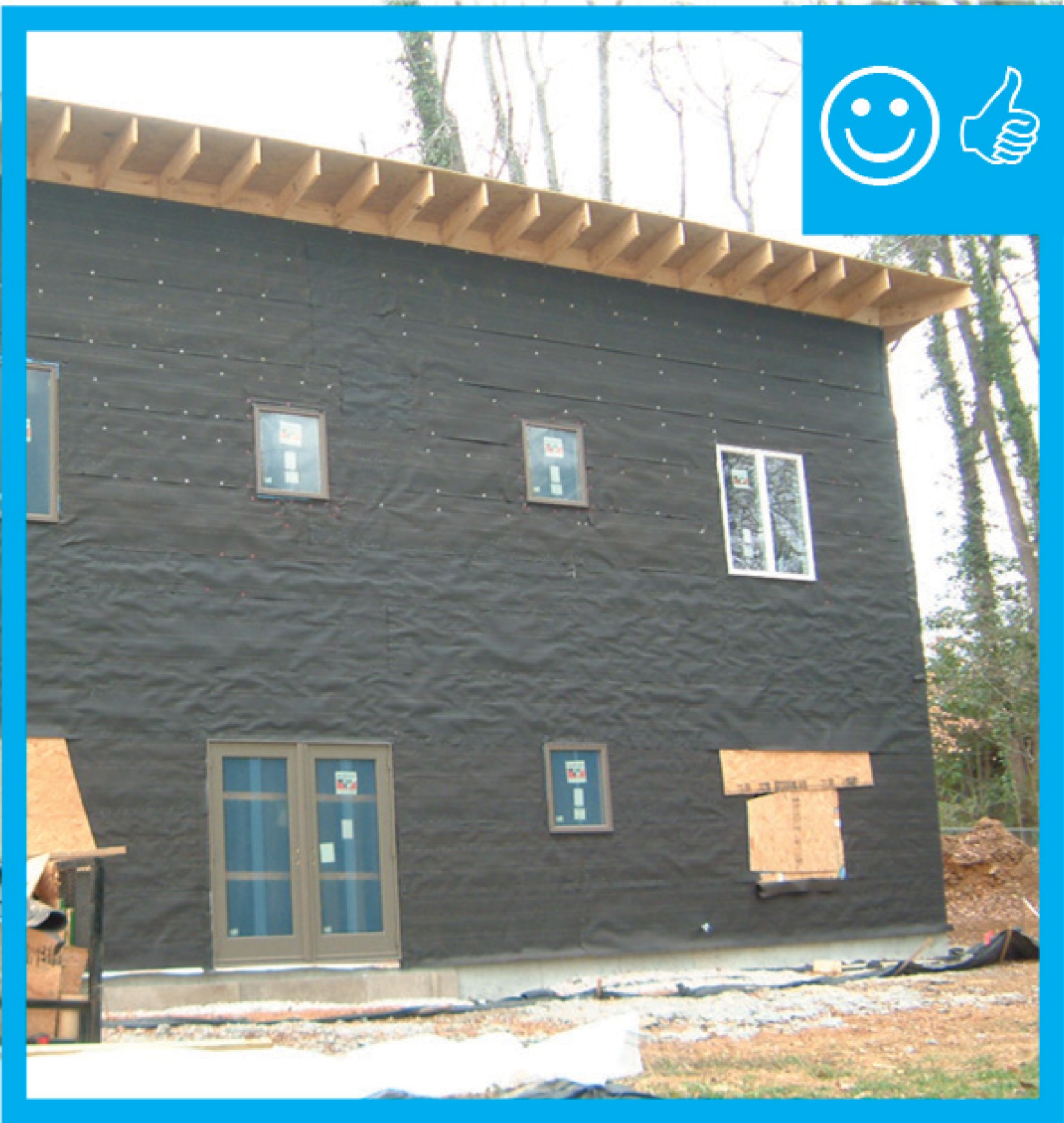
Right – The building felt is installed on all exterior walls and provides a complete drainage system
Image
Right – the building on the right employs light-colored walls, deep tinting, and deeply recessed windows to minimize solar heat gain
Image
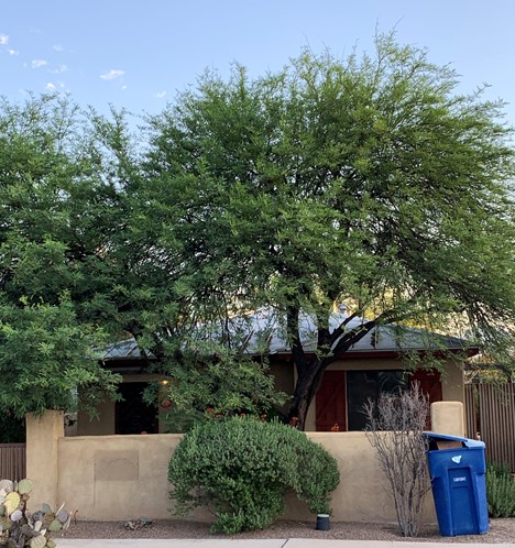
Right – The canopy of this tree is high enough to allow views out the windows of this home while providing excellent shade to walls, windows, and roof.
Image
Right – The coated OSB sheathing can take the place of house wrap to serve as the weather-resistant barrier because it is sealed at the seams with a paint-on flashing.
Image
Right – The corridor in this multistory building is pressurized with outdoor supply air.
Image
Image

Right – The double compressor unit supplies multiple interior minisplit heat pump heads.
Image

Right – The double-pane windows have low-emissivity coatings on three surfaces to reduce heat transfer through the glass allowing in views but preventing heat loss in winter and heat gain in summer.
Image
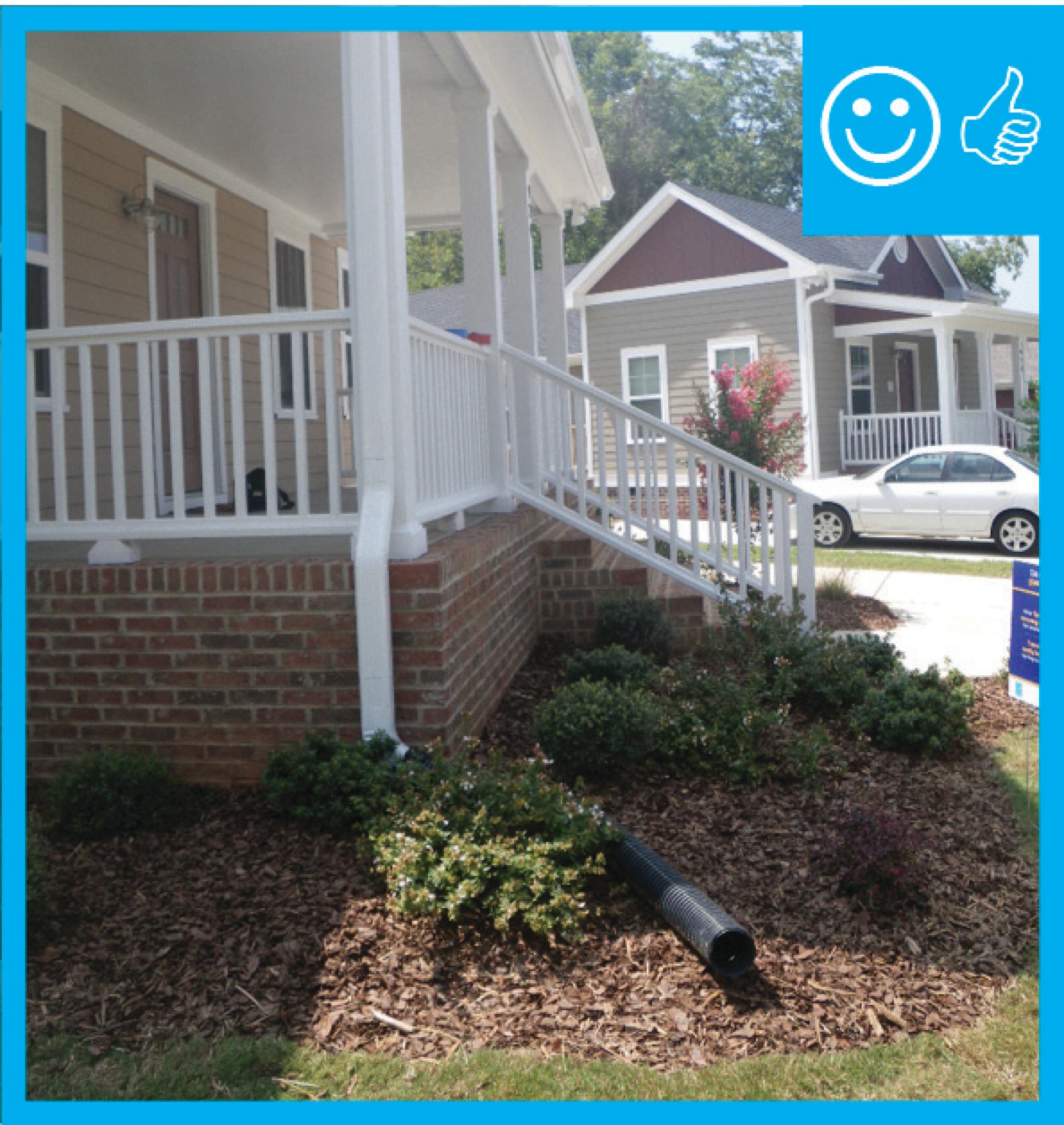
Right – The downspout pipe is far enough away from the foundation to prevent moisture problems
Image
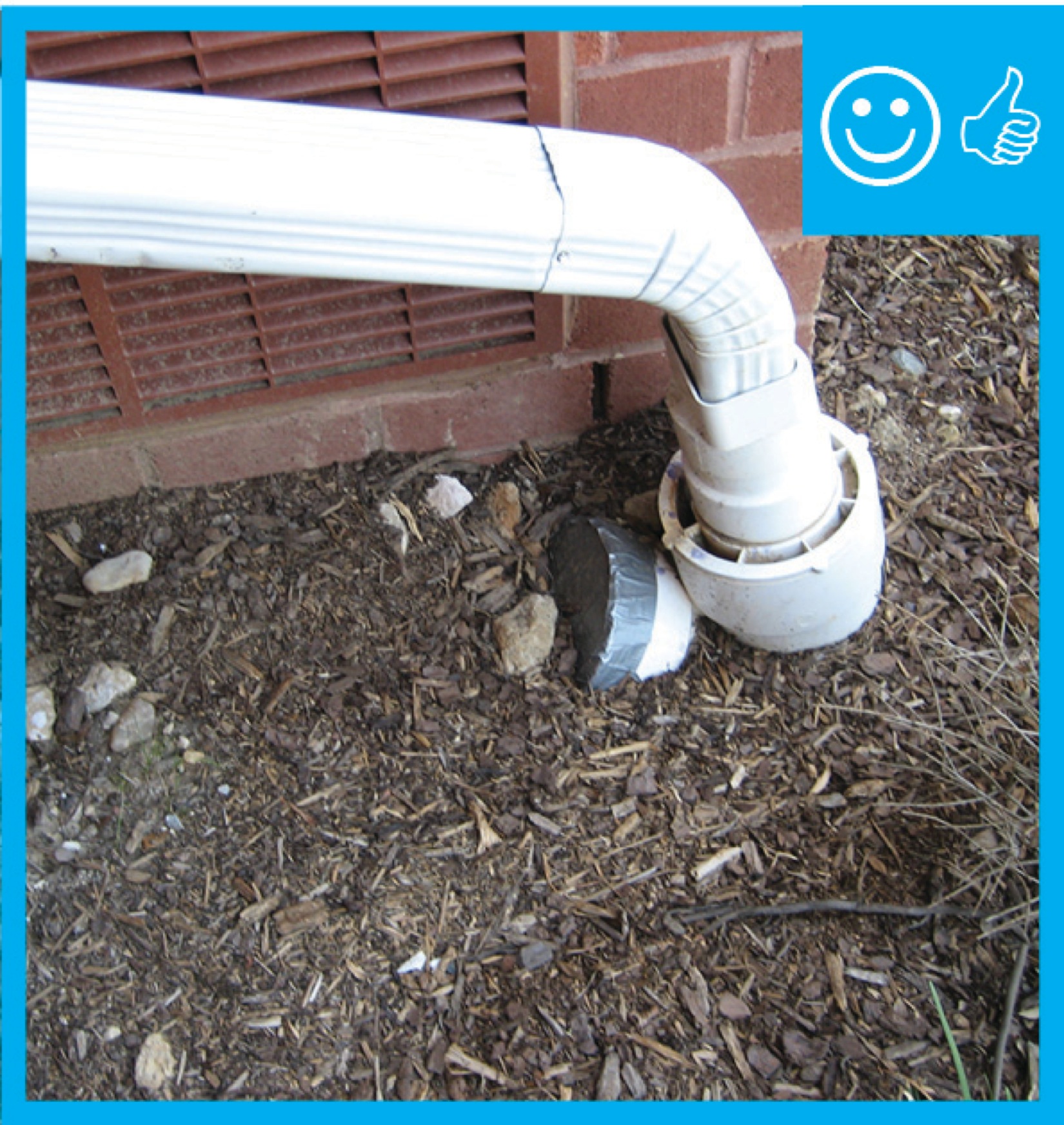
Right – The downspout terminates into a catchment system that moves water away from the foundation of the house
Image

Right – The drain slopes away from the foundation and terminates at the proper distance
Image
Right – The drain tile connects to a sump pump which will pump water away from the foundation
Image
Right – The drain tile is installed along the bottom of the entire foundation footing
Image
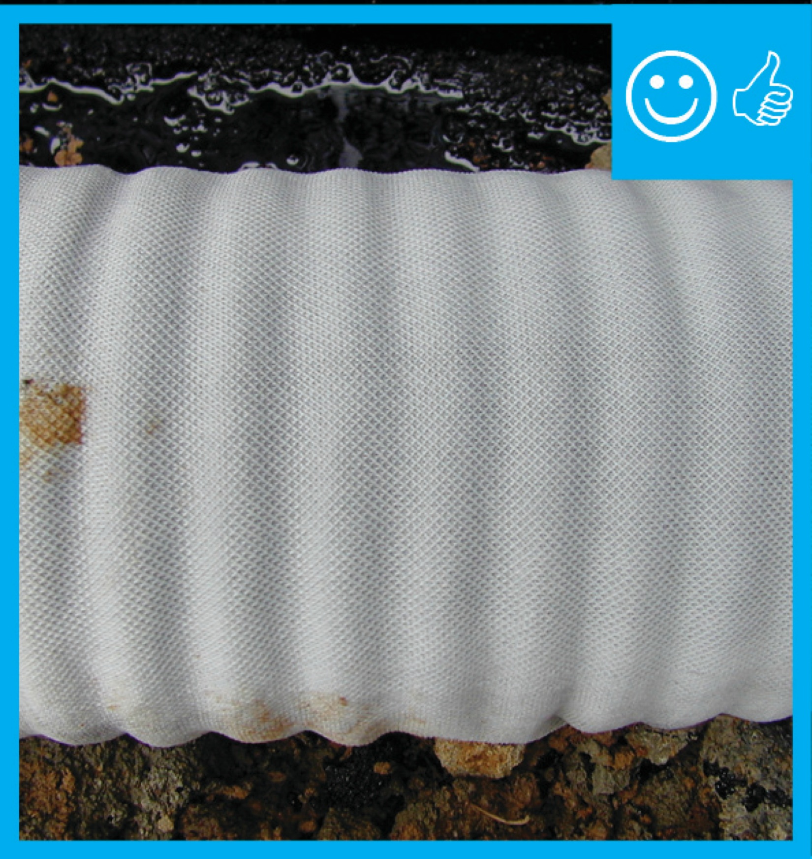
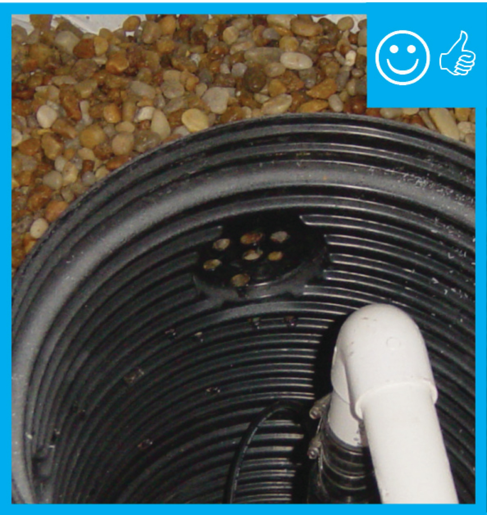
Right – The drain tile is wrapped in fabric which will prevent it clogging with debris
Image

Right – The ductless minisplit in this open area is installed in the ceiling rather than on a wall.
Image
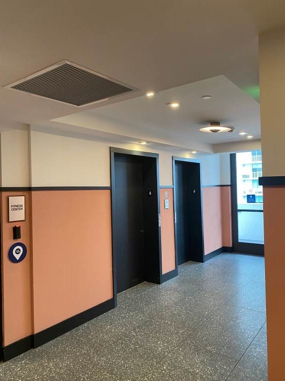
Right – The elevator lobby of this multistory building is pressurized with outdoor air supplied to the space through this ceiling supply register.
Image

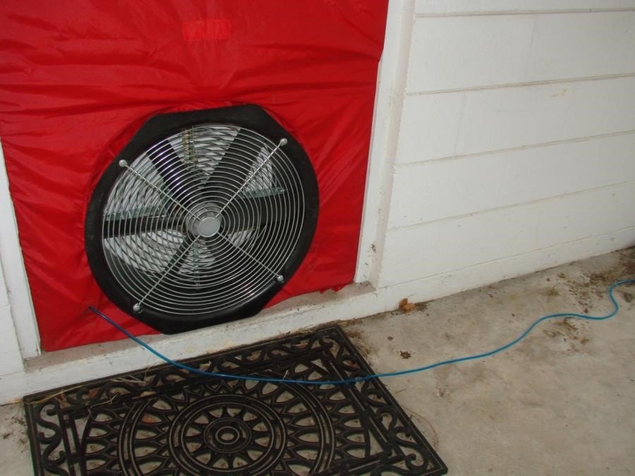
Right – The energy rater used a window to test whole-house air leakage with this blower door testing equipment.