Showing results 201 - 250 of 467
Image
Right – Cantilever has been properly insulated, air sealed, and cavity has been blocked.
Image
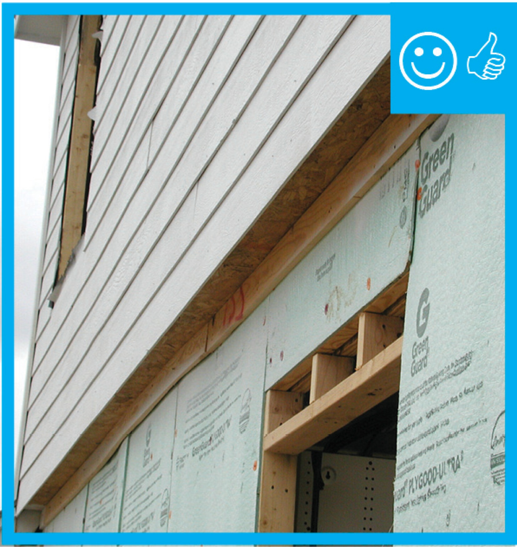
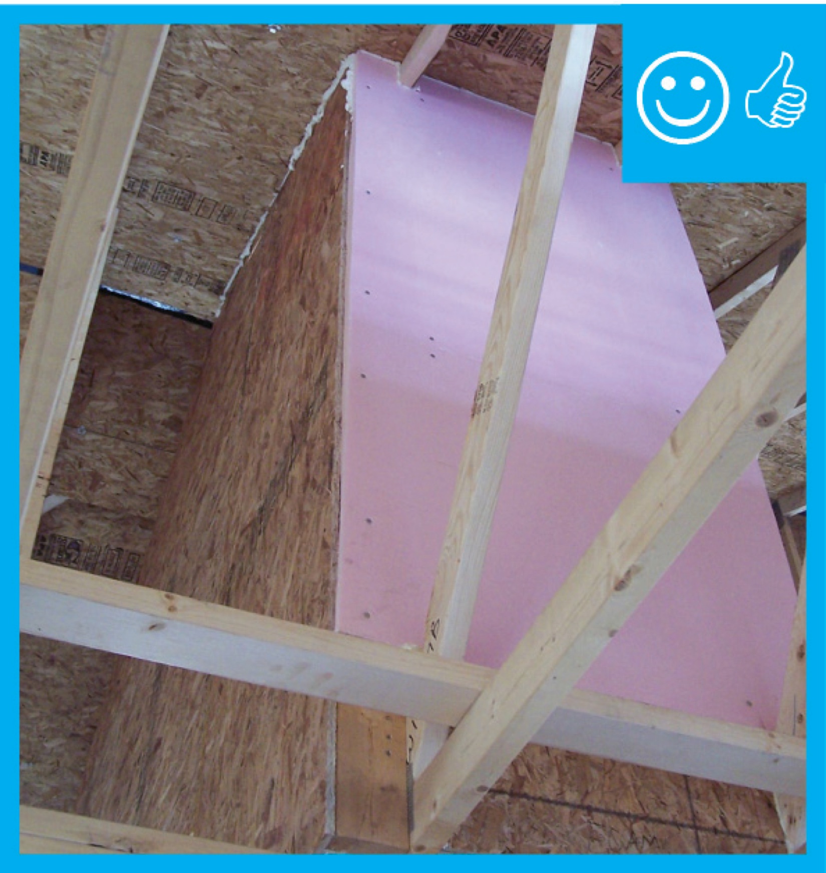
Right – Chase capped with rigid air barrier and duct work penetrations properly sealed
Image
Image
Image

Image
Image
Image

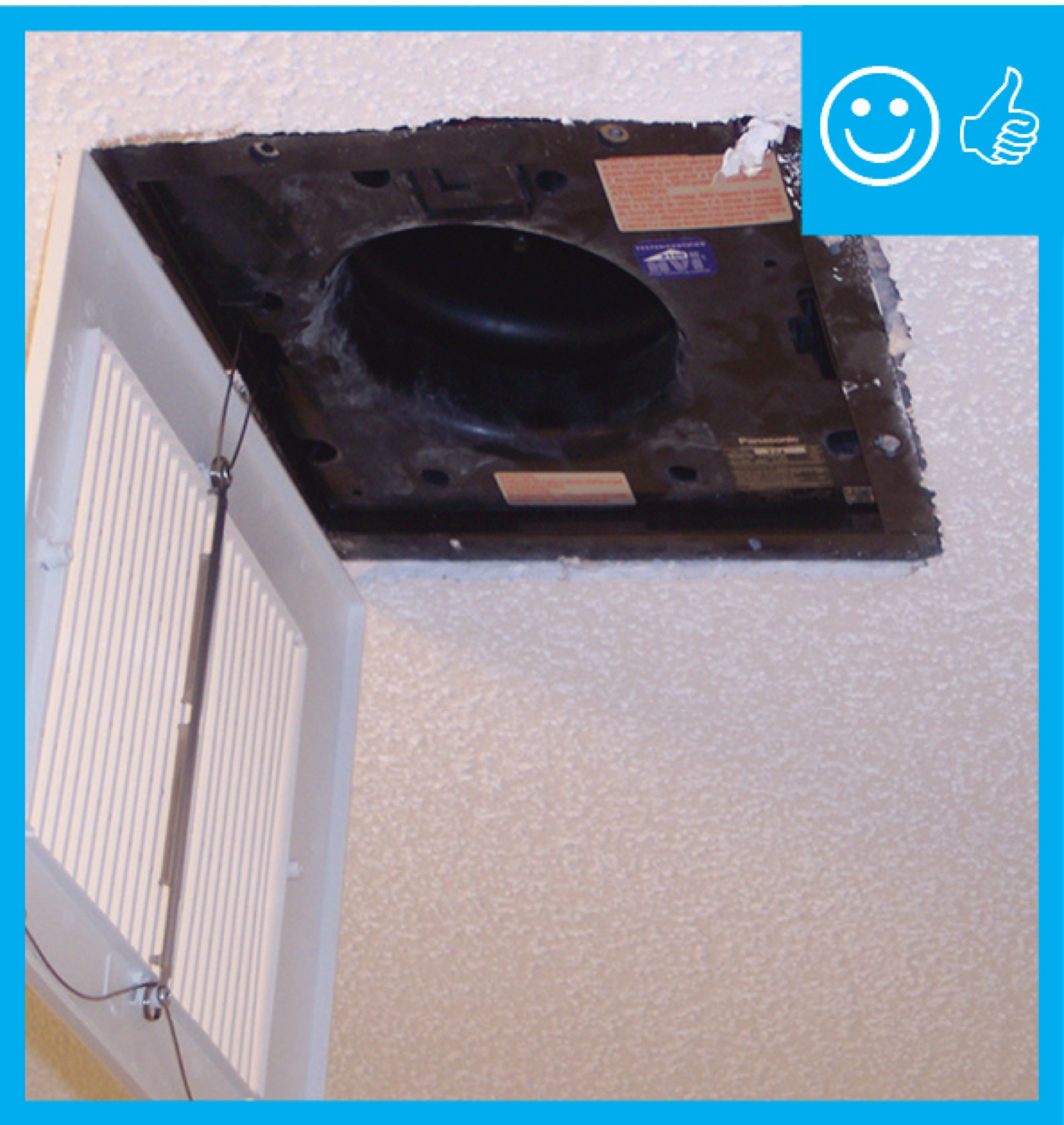
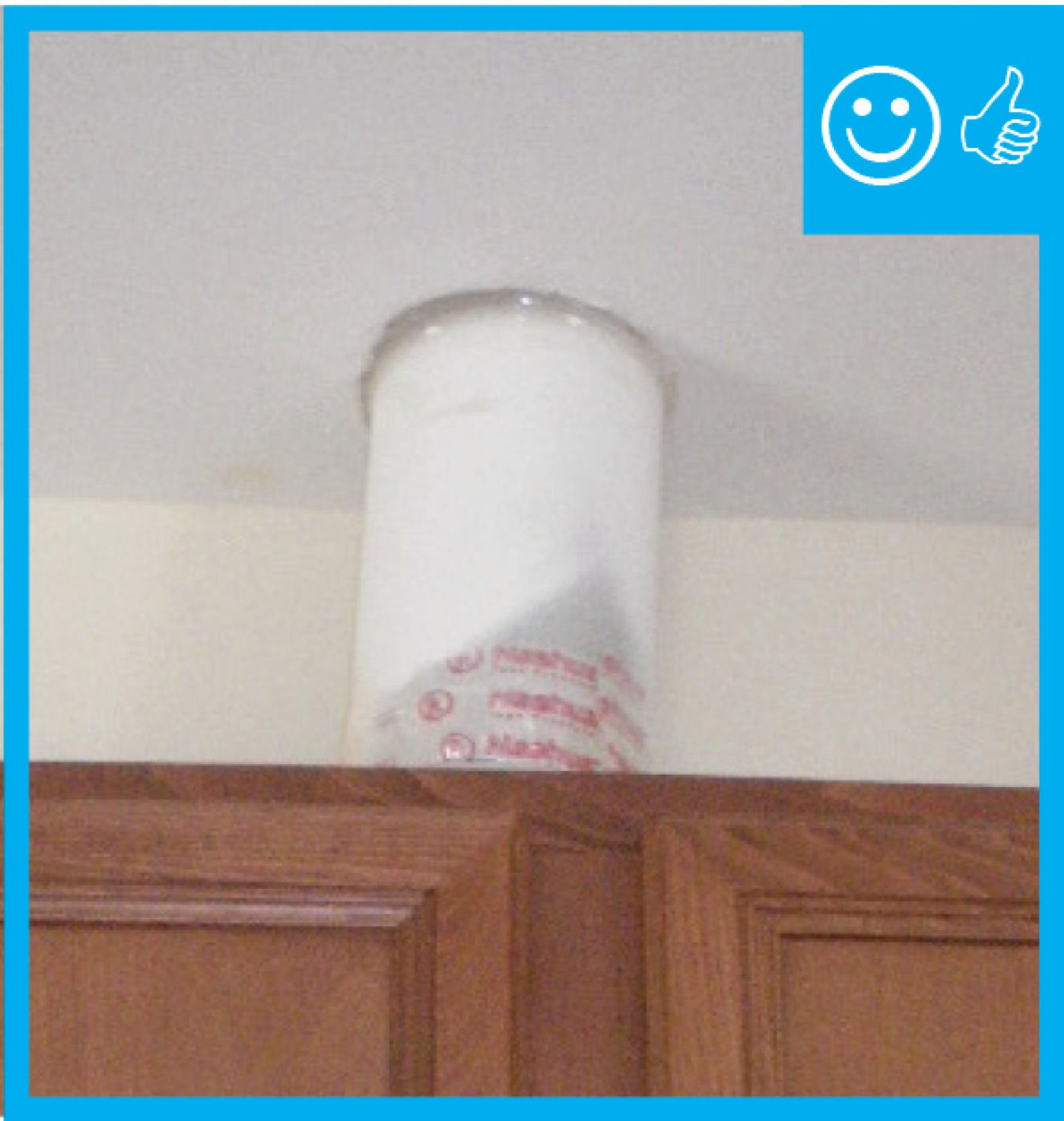
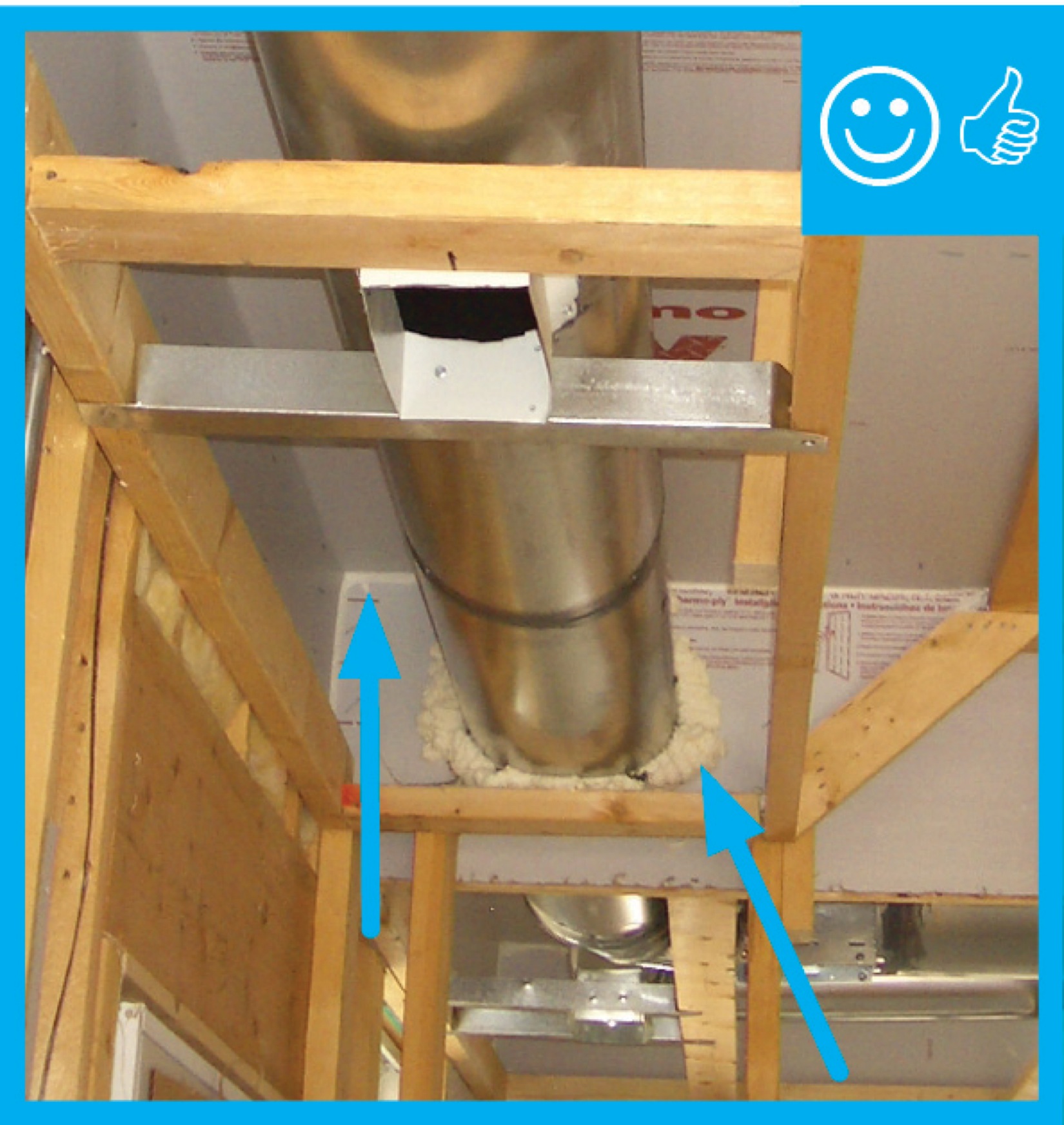
Right – Fan with a cleanly cut and properly sized hole has been air sealed to drywall
Image

Image
Image

Image
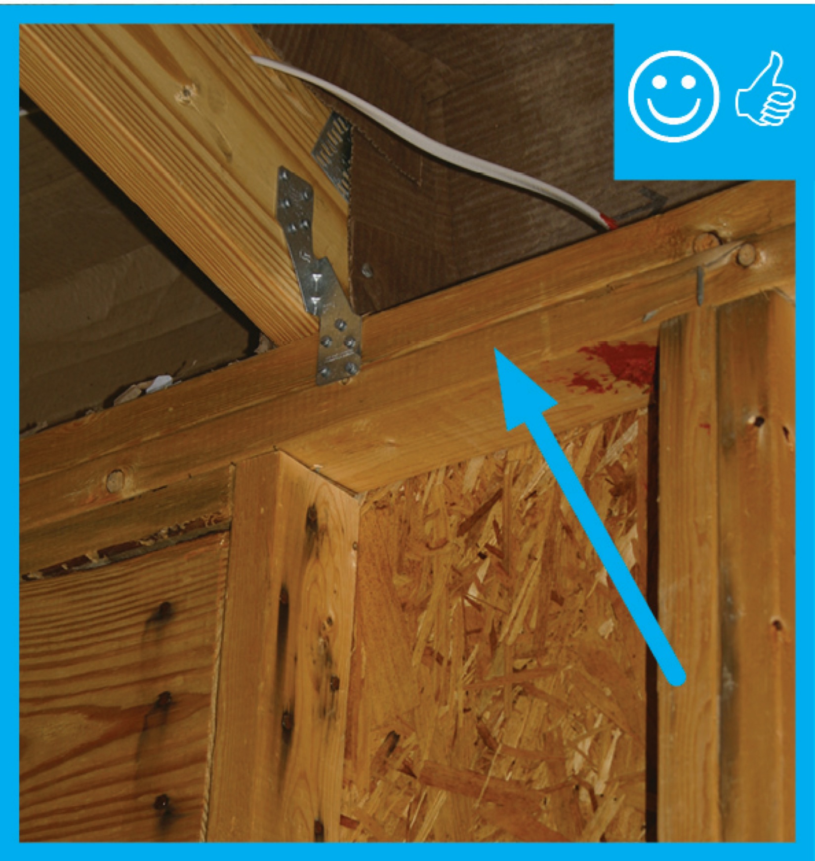
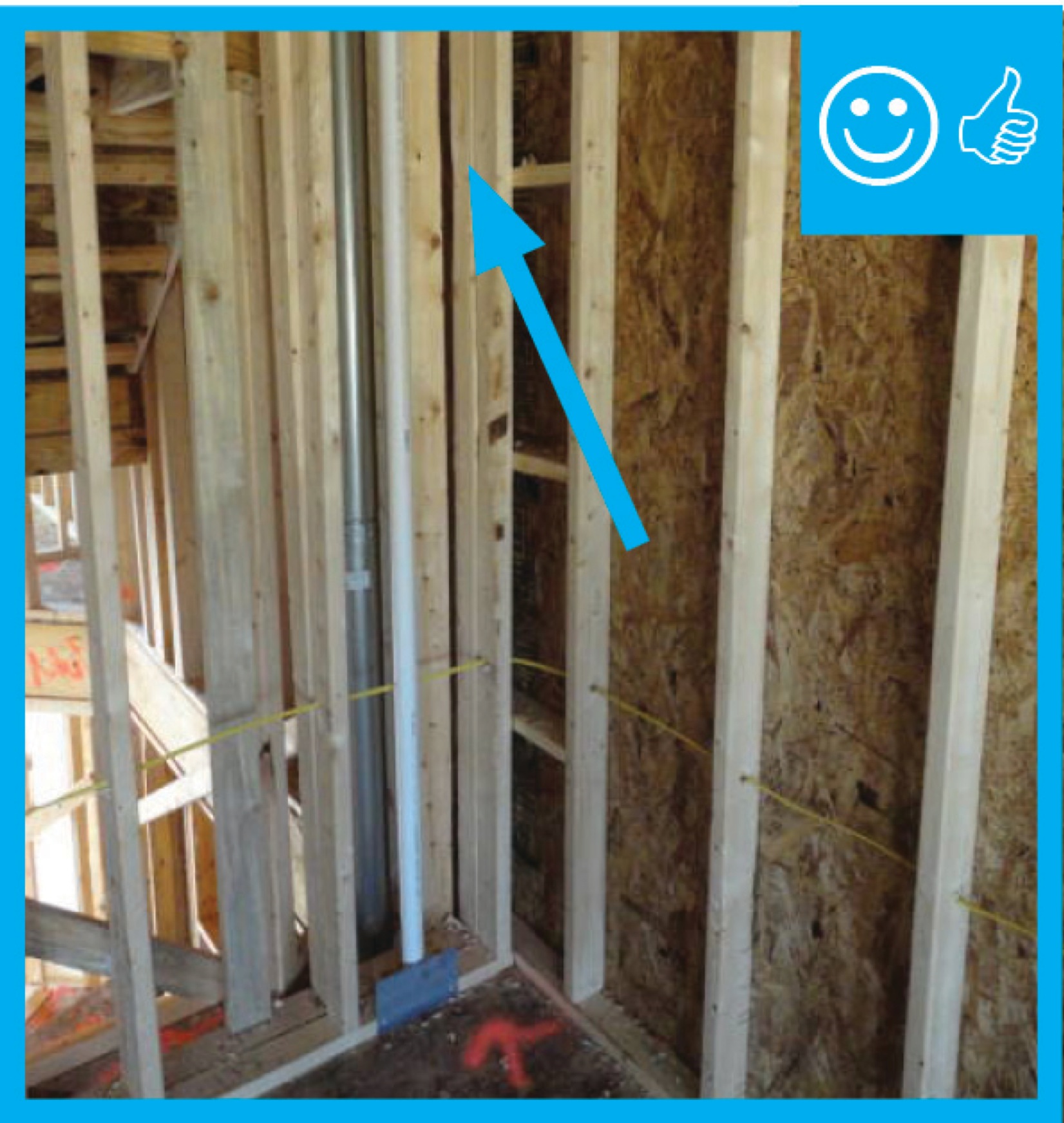
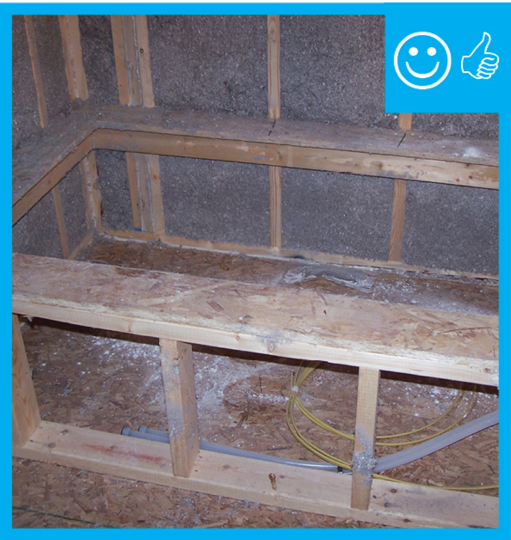
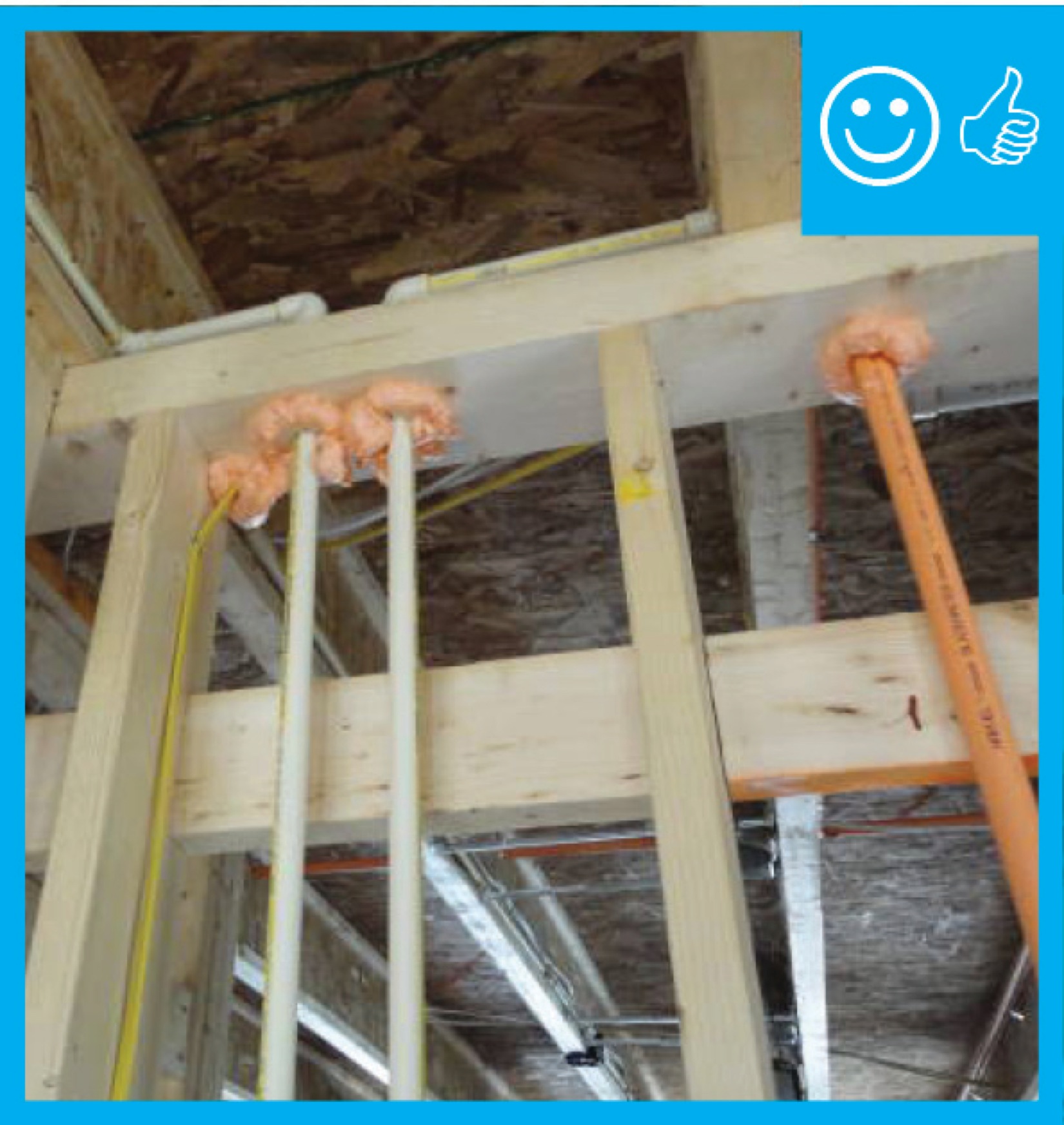
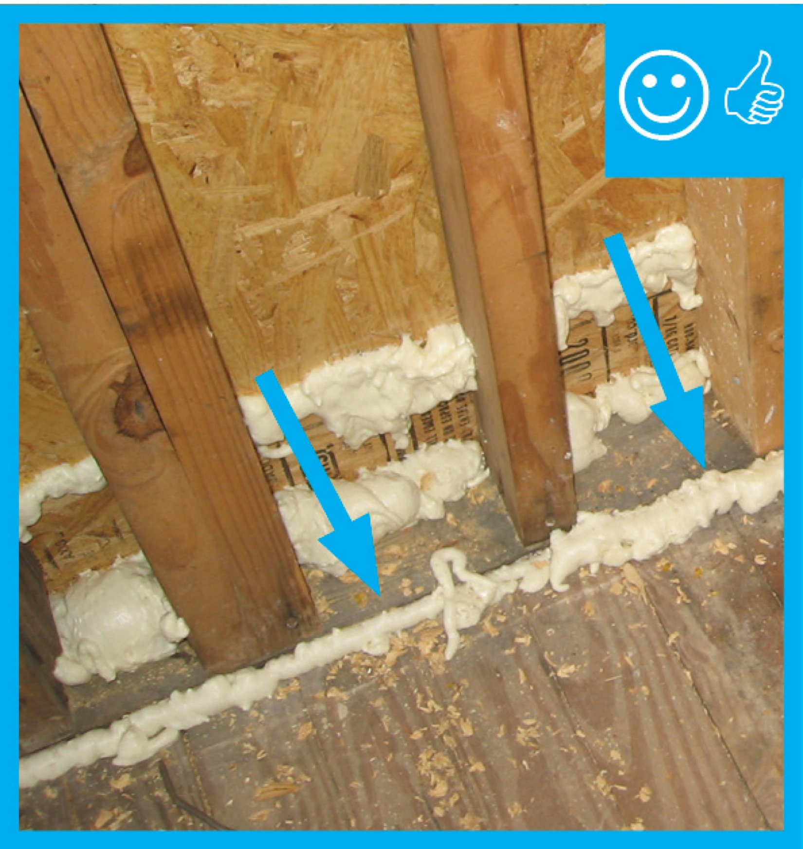
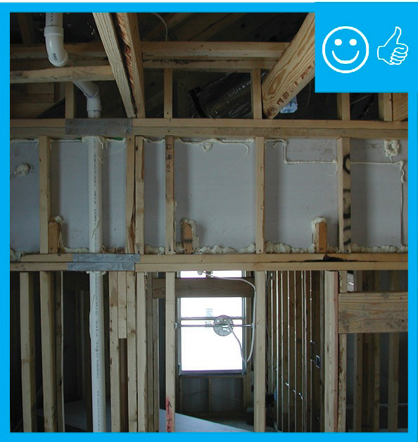
Right – Full length 2x6 nailer has been installed to allow space for insulation at wall intersection
Image
Image
Right – Graphite enhanced EPS fills these SIP panels, providing additional insulation value.
Image
Image
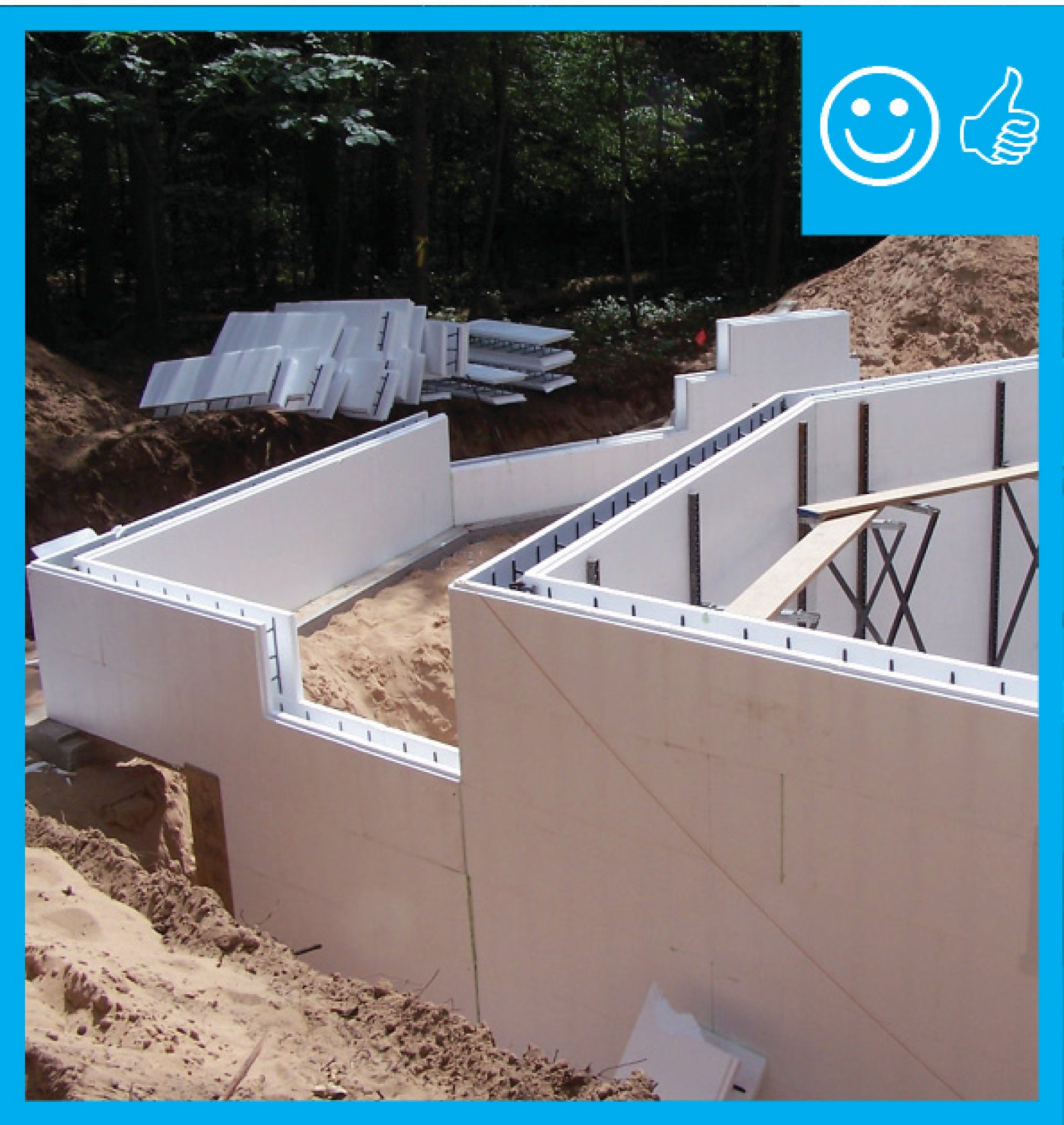
Right – ICFs are being installed to create a continuous air and thermal boundary
Image
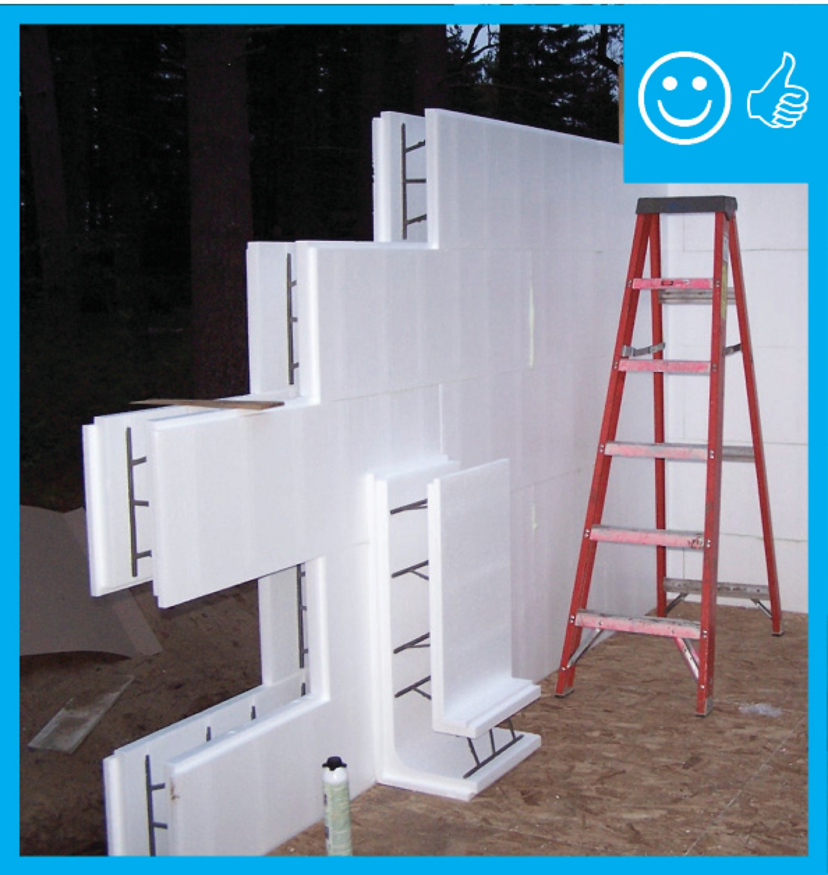
Right – ICFs are being installed to create a continuous air and thermal boundary
Image

Right – ICFs are being installed to create a continuous air and thermal boundary
Image

Right – ICFs are being installed to create a continuous air and thermal boundary
Image
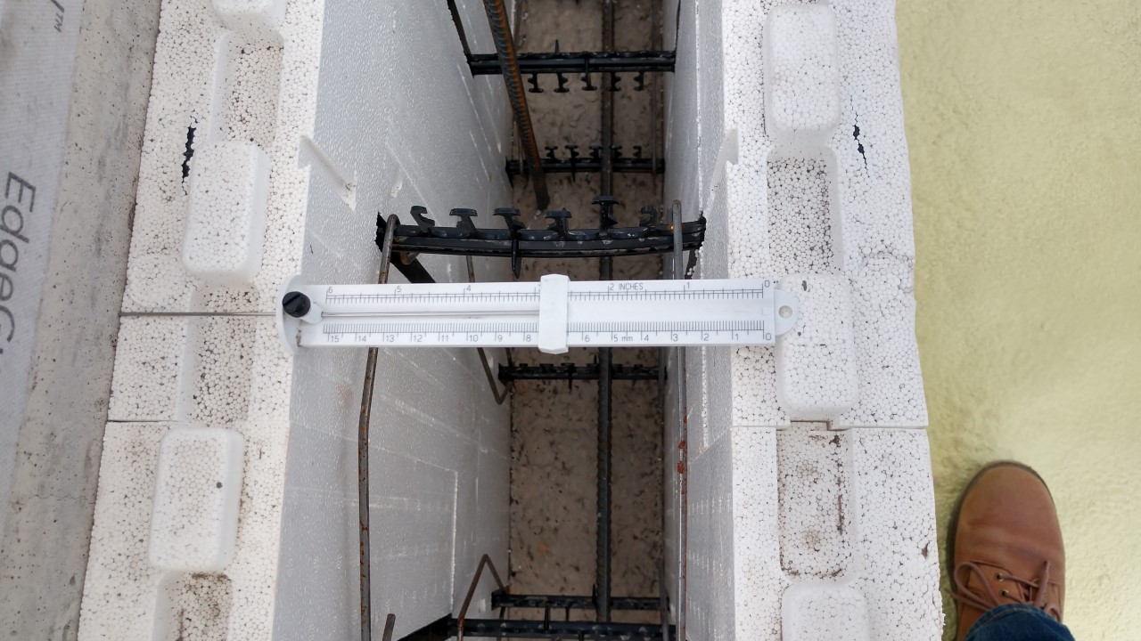
Right – Insulated concrete form (ICF) blocks are stacked like bricks, then rebar is set horizontally and vertically in the plastic spacers, then concrete is poured; the rigid foam and spacers stay in place to add support and thermal resistance to the wall
Image
Image
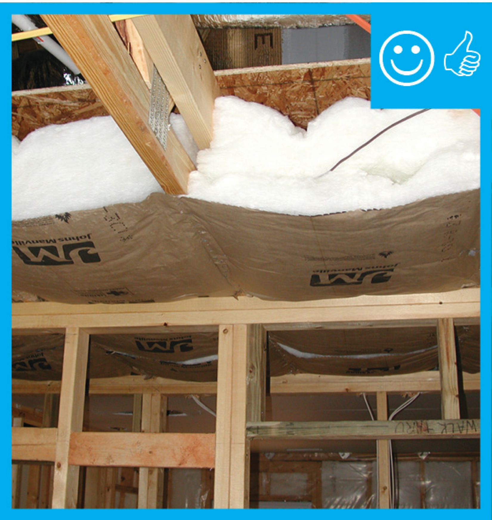
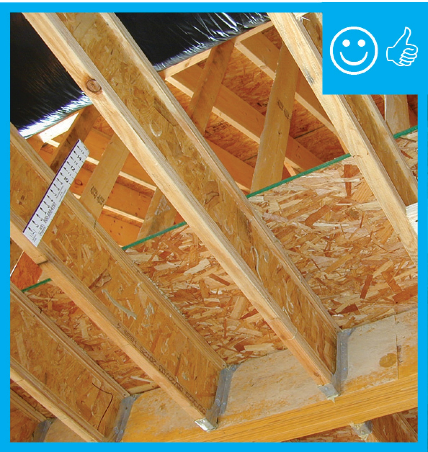
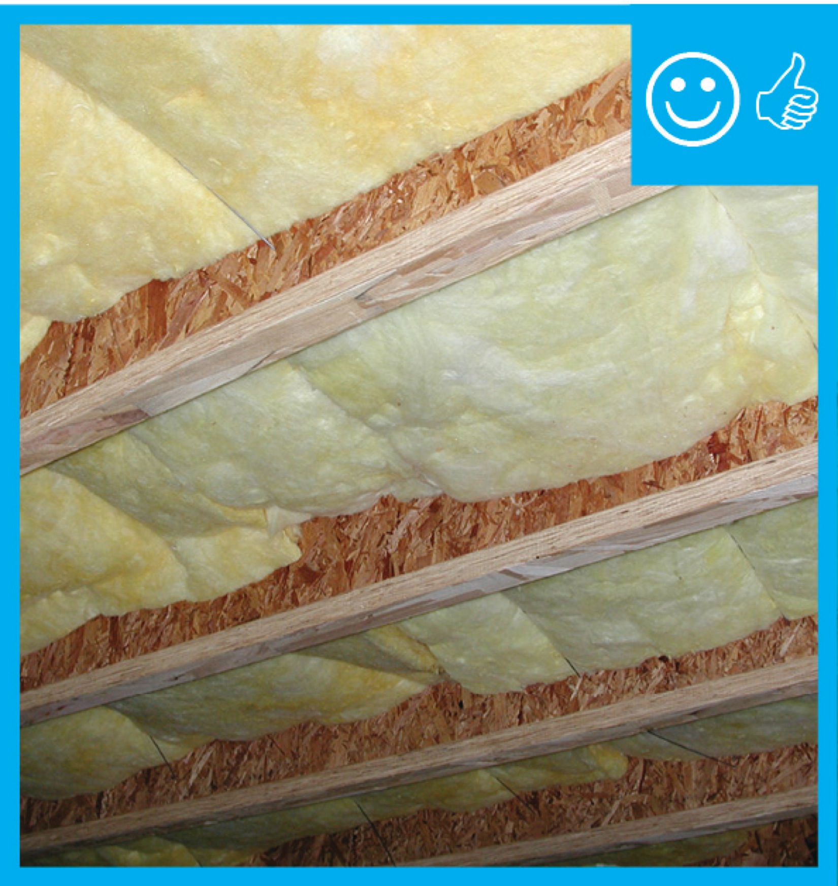
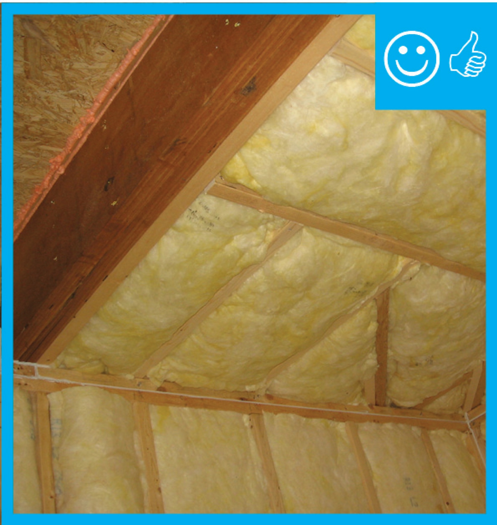
Right – Insulation installed to correct depth and will be aligned with air barrier
Image
Image

Image
Image
Image
Image
Image
Image
Image
Image
Image
Image

Image
Image
Image
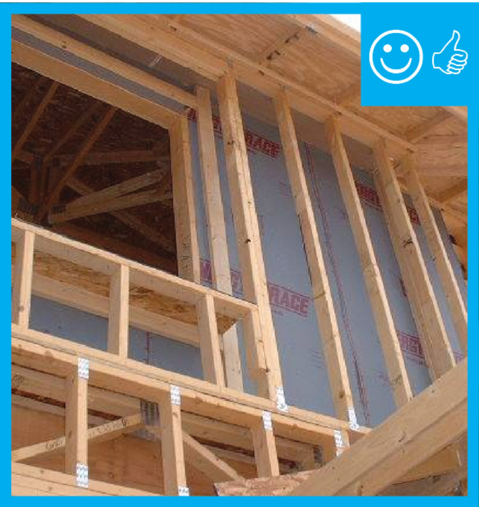
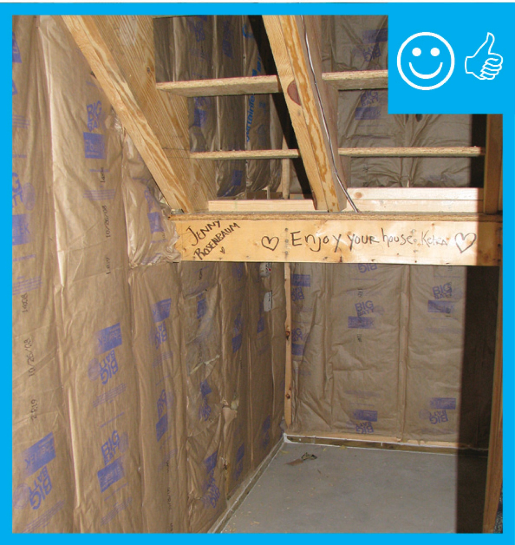
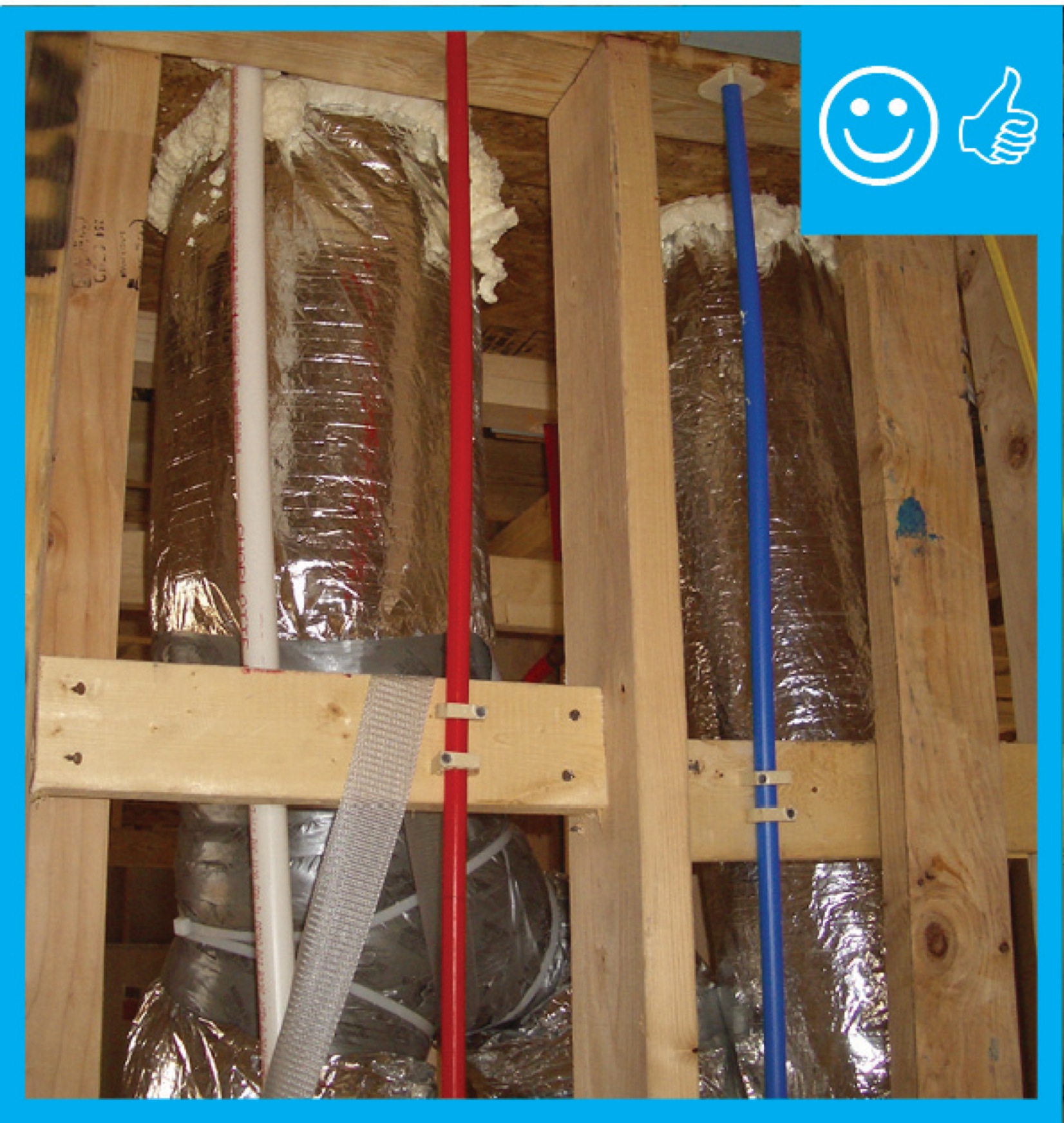
Right – Rigid air barrier installed between double-wall assembly. Inside cavity will be insulated
Image
Image
Image
Image

Image
Image
Image

Image
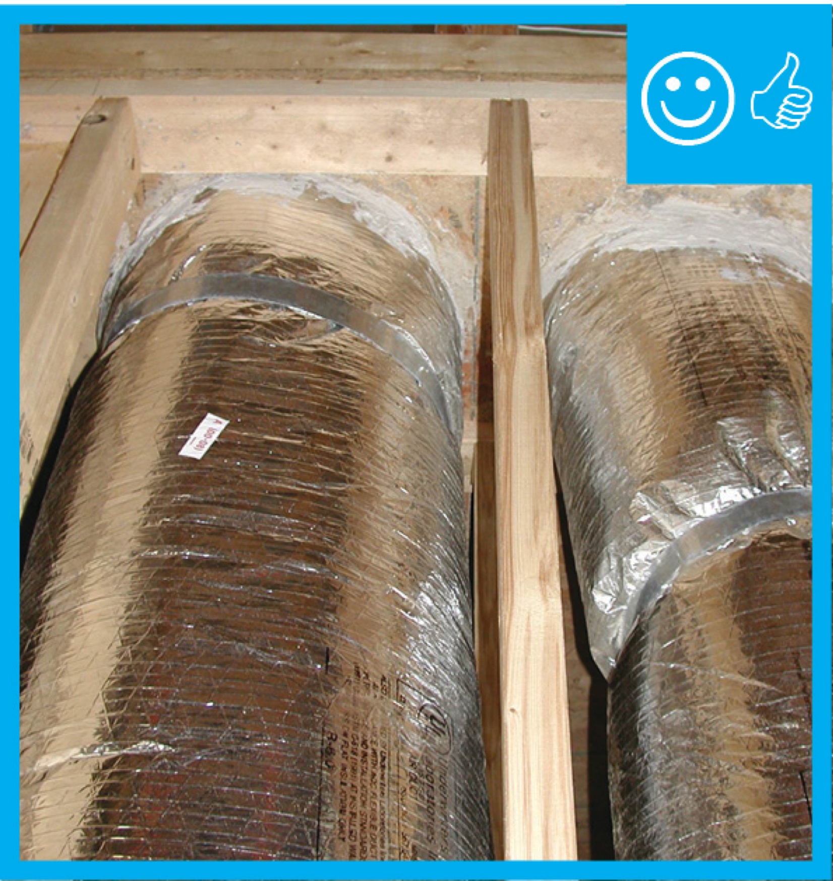
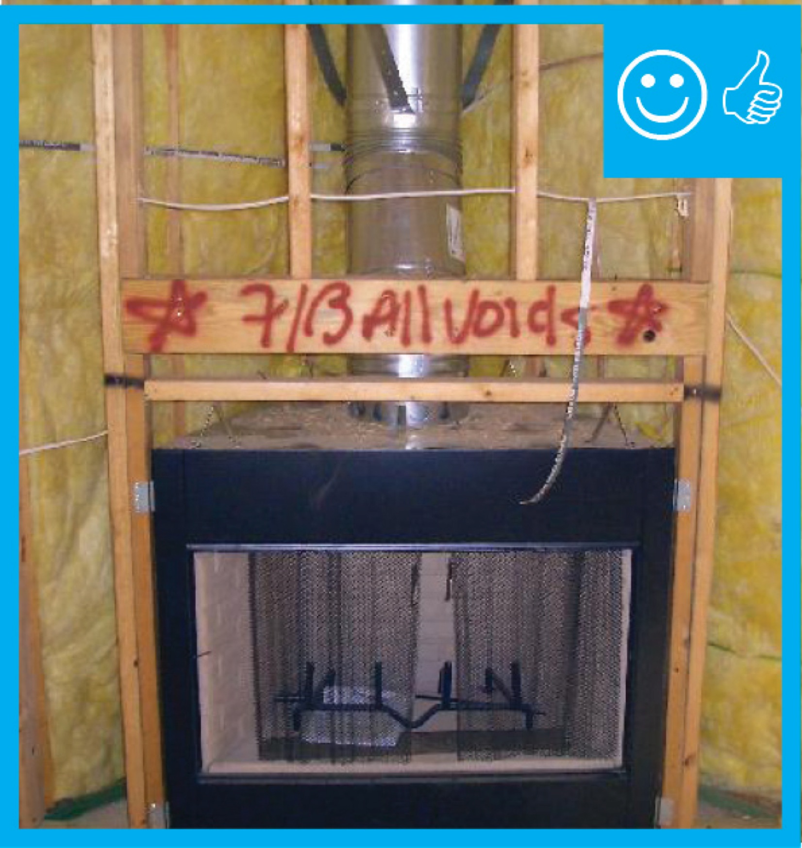
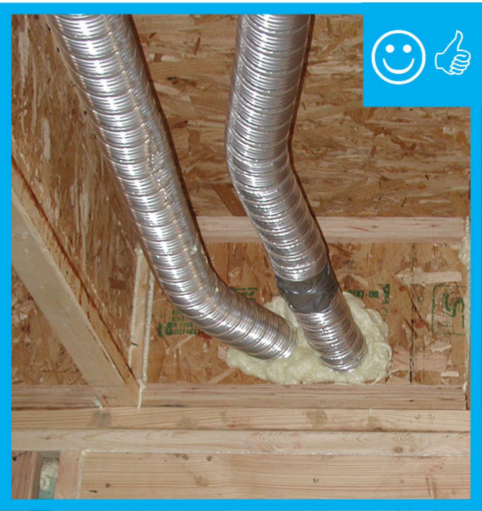
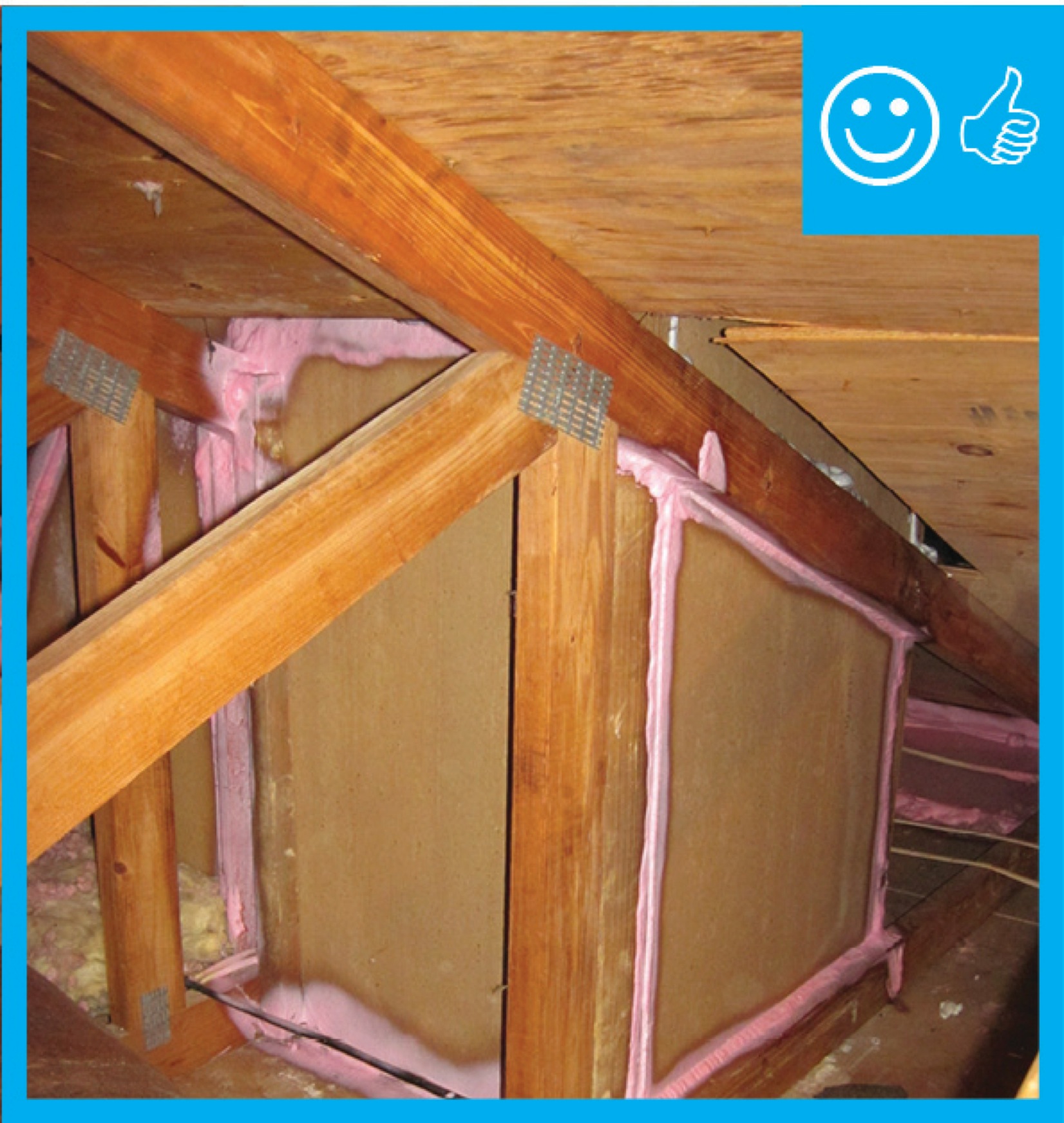
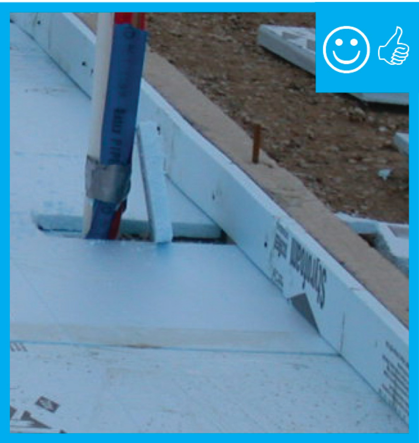
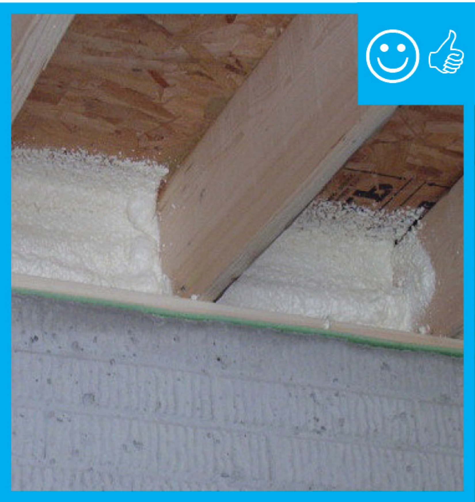
Right – Spray foam was installed at the sheathing intersection as well as the sill plate to sub-floor connection.
Image
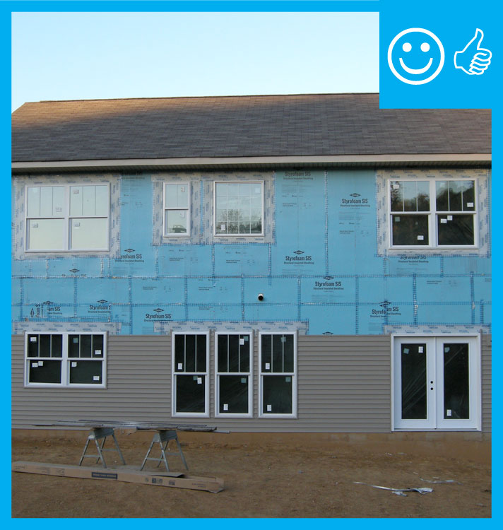
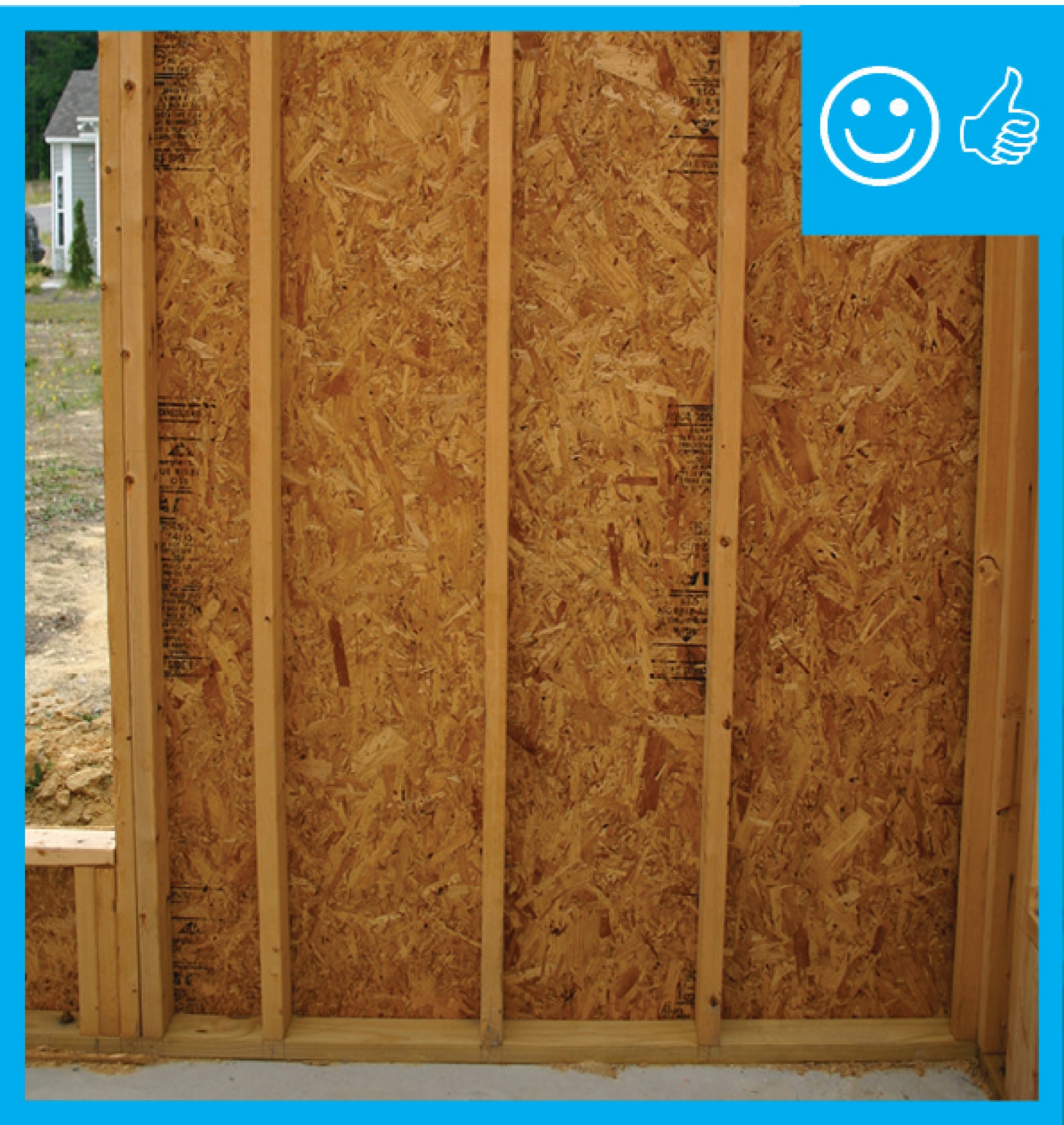
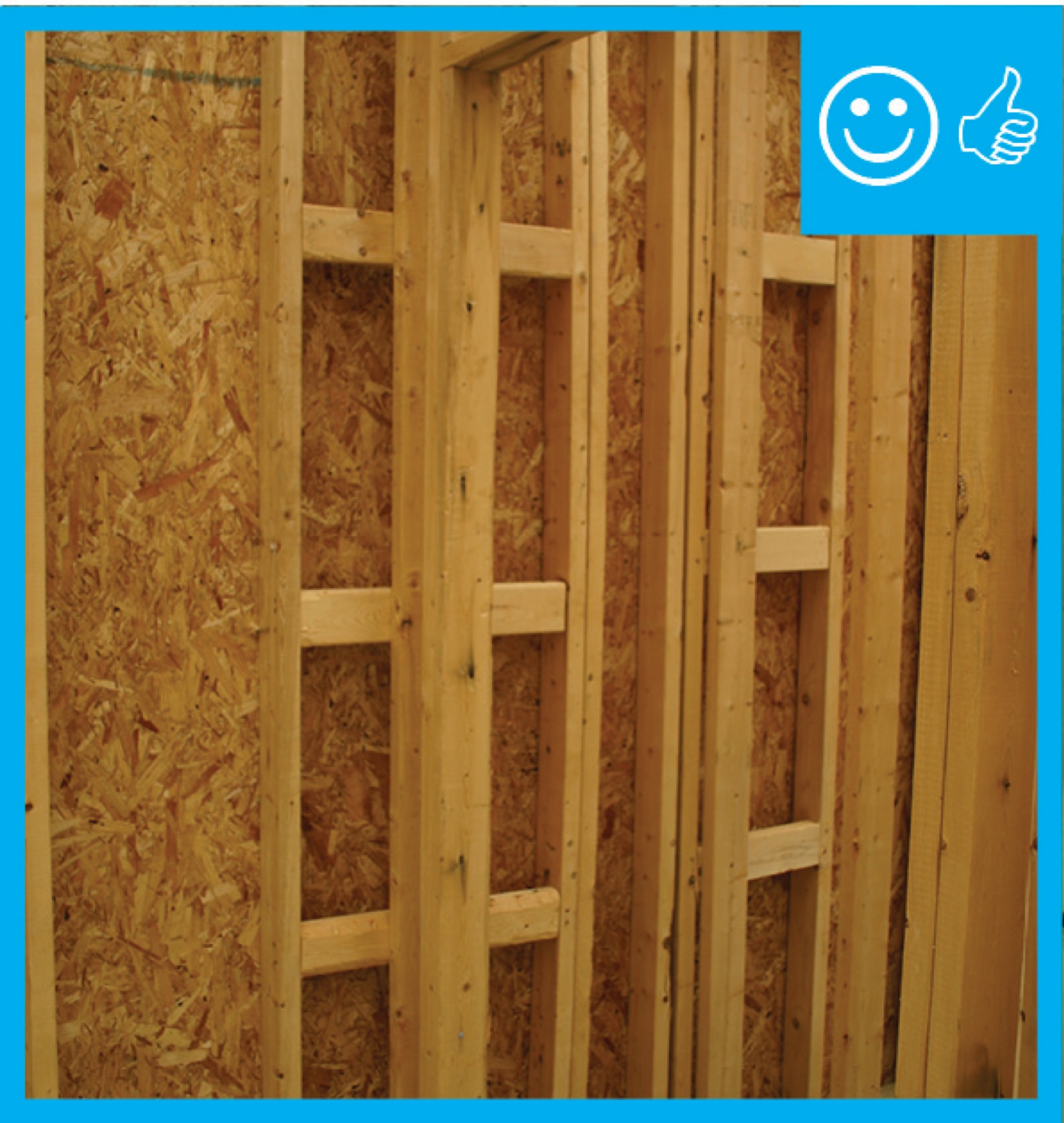
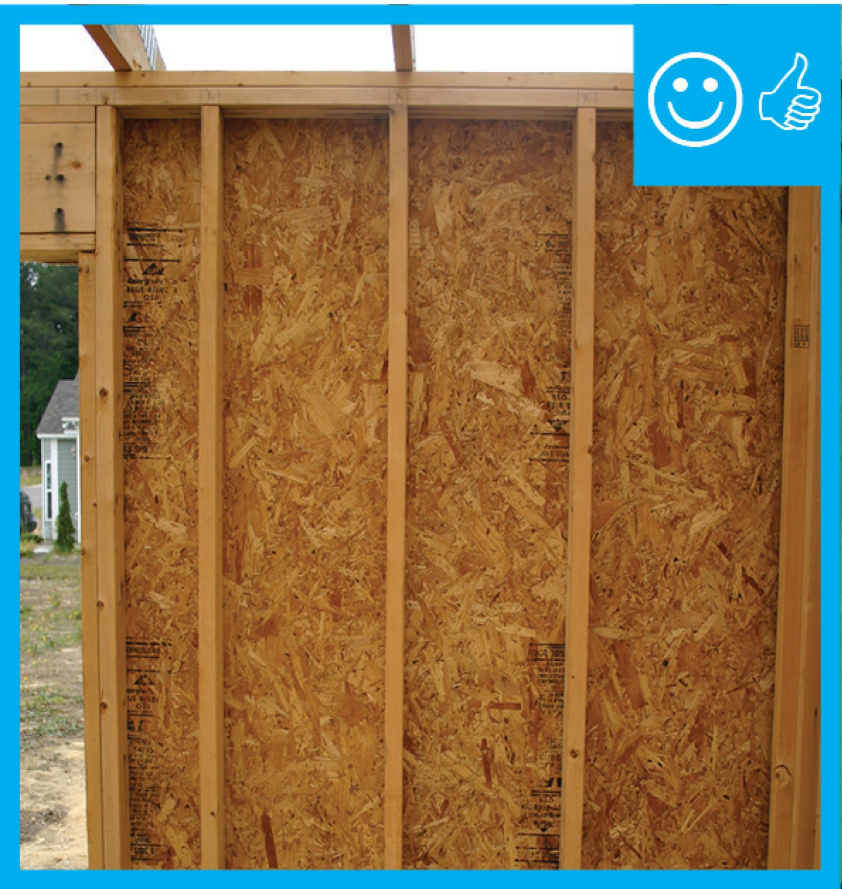
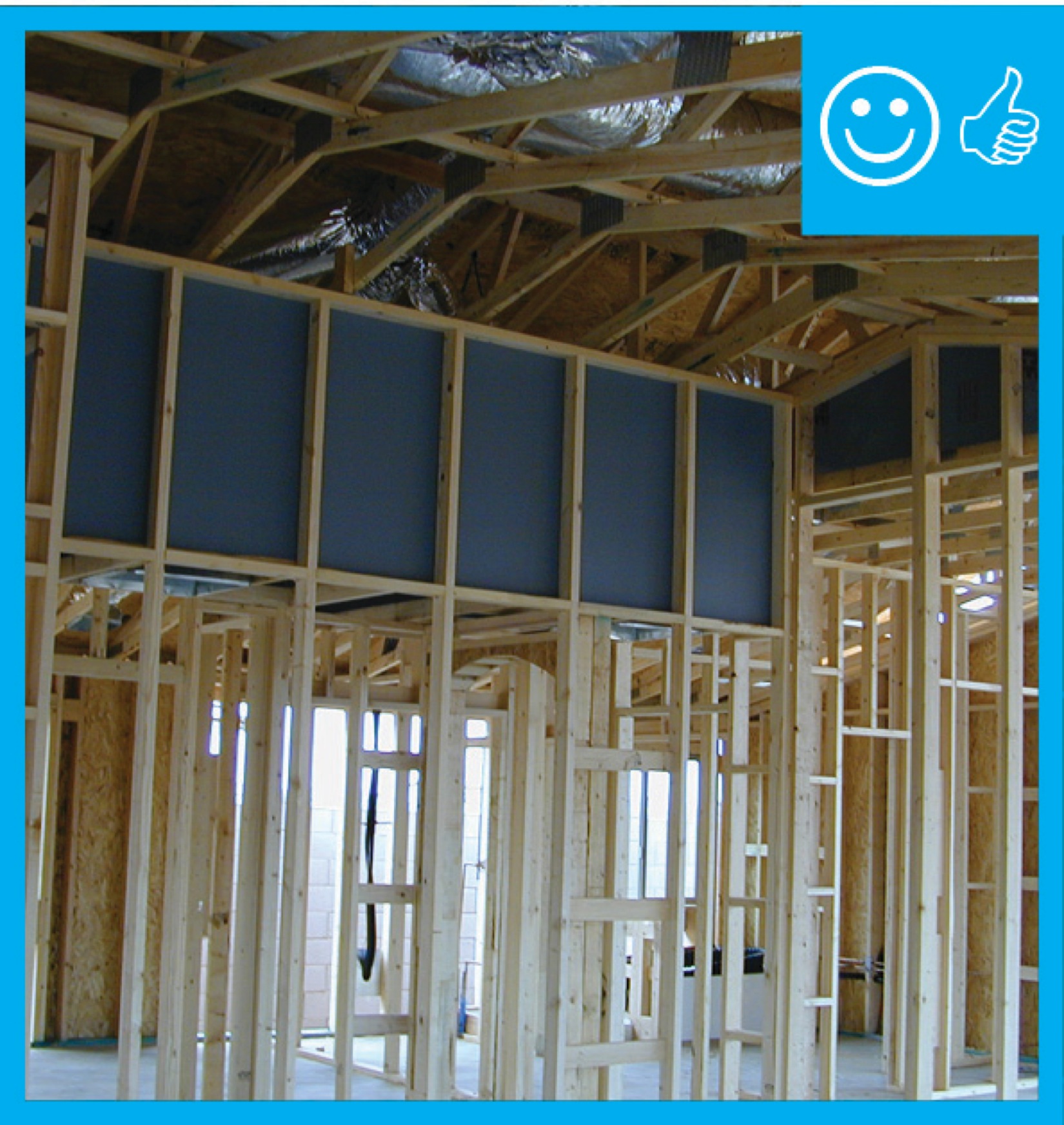
Right – Structural insulated sheathing can provide racking strength (lateral load resistance), and serve as an air barrier and thermal barrier if installed according to manufacturer’s specifications with taped, sealed seams
Image
Image
Image
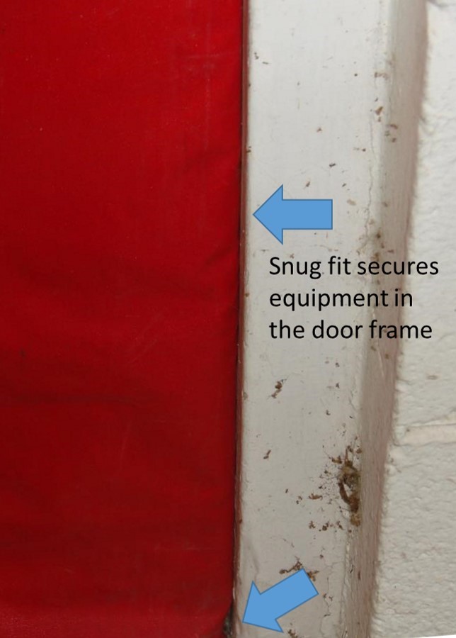
Right – The blower door is installed snugly and securely to the door frame during testing
Image
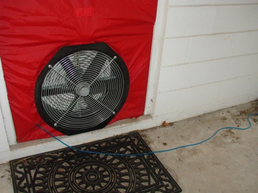
Right – The blower door pressure reference hose is placed well away from the outdoor side of the fan