Showing results 1 - 250 of 281
Image
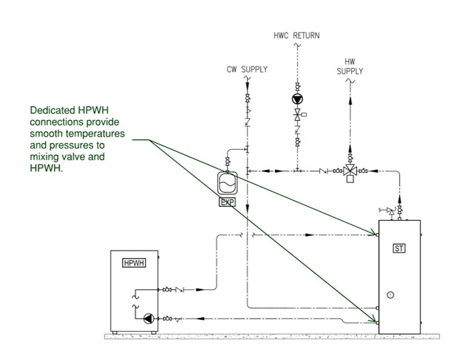
Right: dedicated tank connections for HPWH inlet and outlet provide hydraulic separation
Image
Image
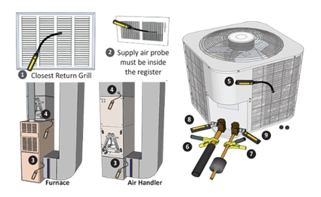
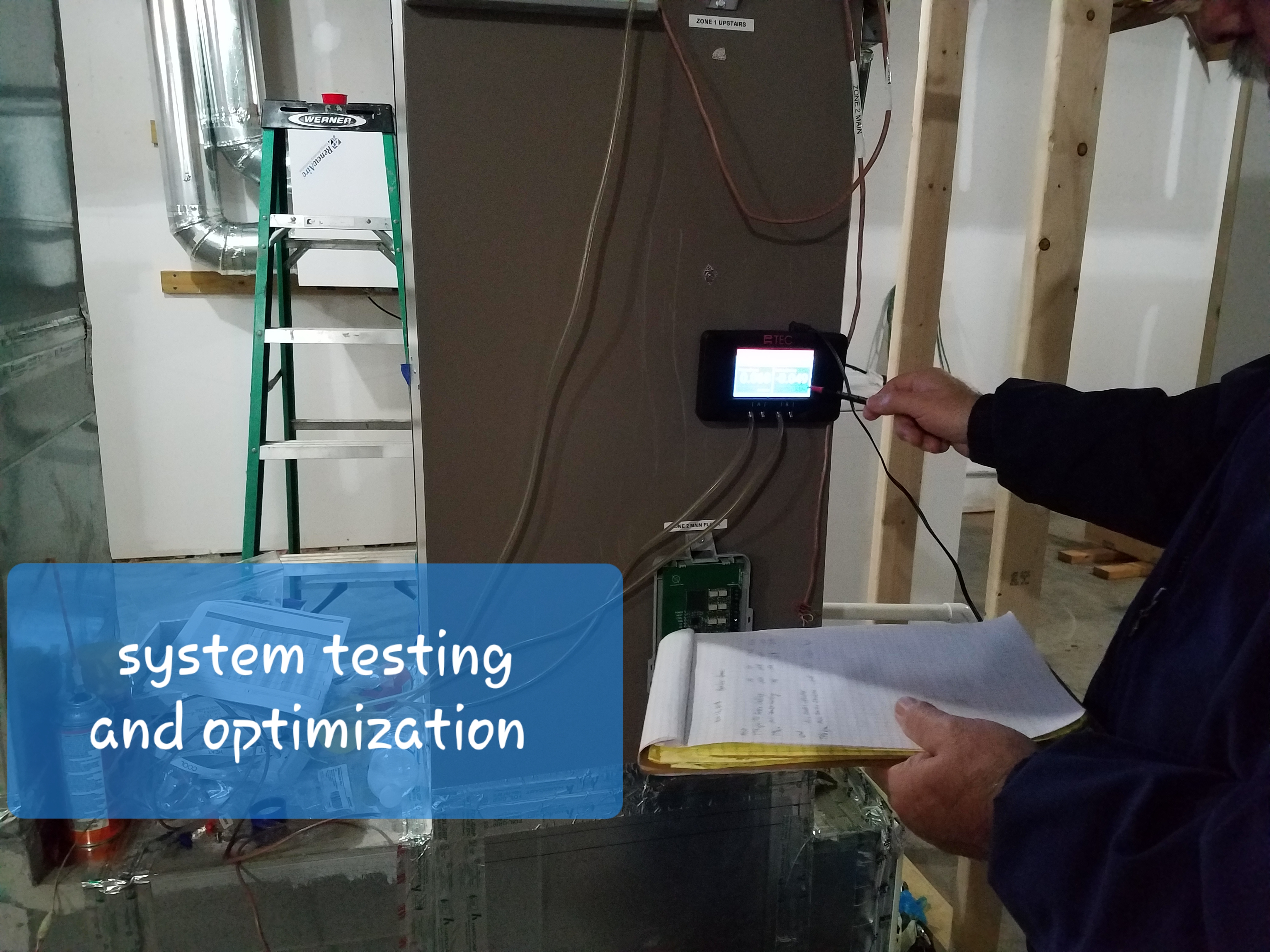
These schematics illustrate temporary deployment locations for probes during the commissioning process; these probes connect to smartphone commissioning applications.
Image

A central heat pump water heating system with a parallel loop tank temperature maintenance configuration uses a multi pass heat pump water heater to provide all the heat for hot water circulation temperature maintenance.
Image
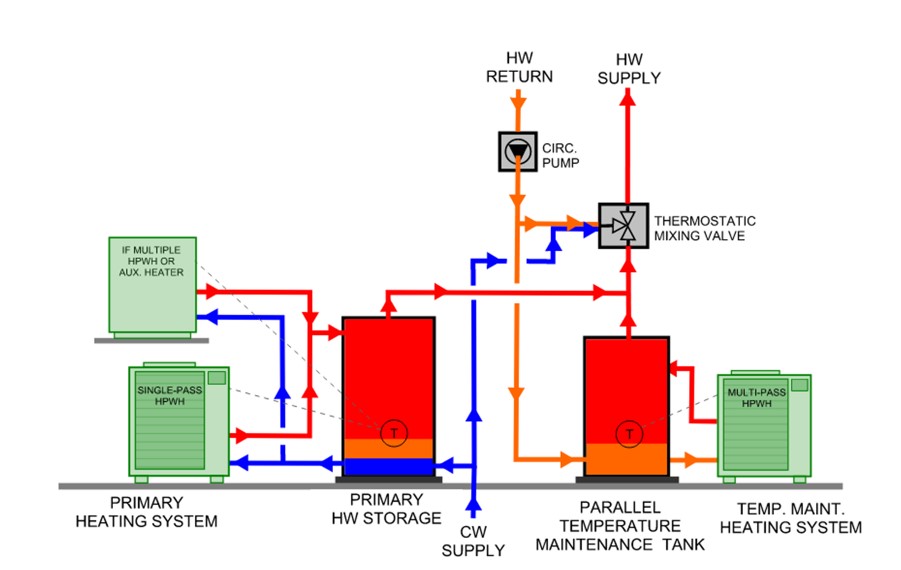
A central heat pump water heating system with a parallel loop tank temperature maintenance configuration uses a multi-pass heat pump water heater to provide all the heat for hot water circulation temperature maintenance
Image
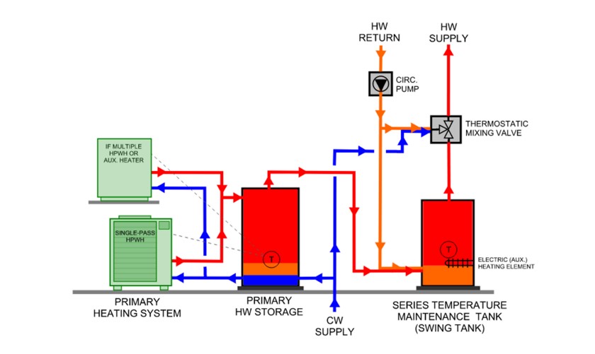
A central heat pump water heating system with a temperature maintenance swing tank configuration uses the water from the primary storage tank to provide most of the heat for hot water circulation temperature maintenance
Image
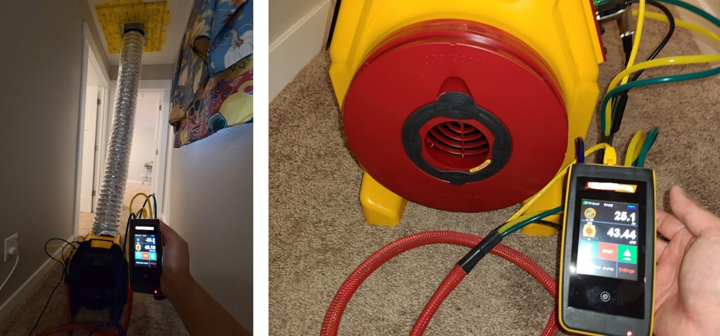
A duct leakage test is performed on a ducted heat pump system using a duct tester (blower fan) and a digital manometer.
Image
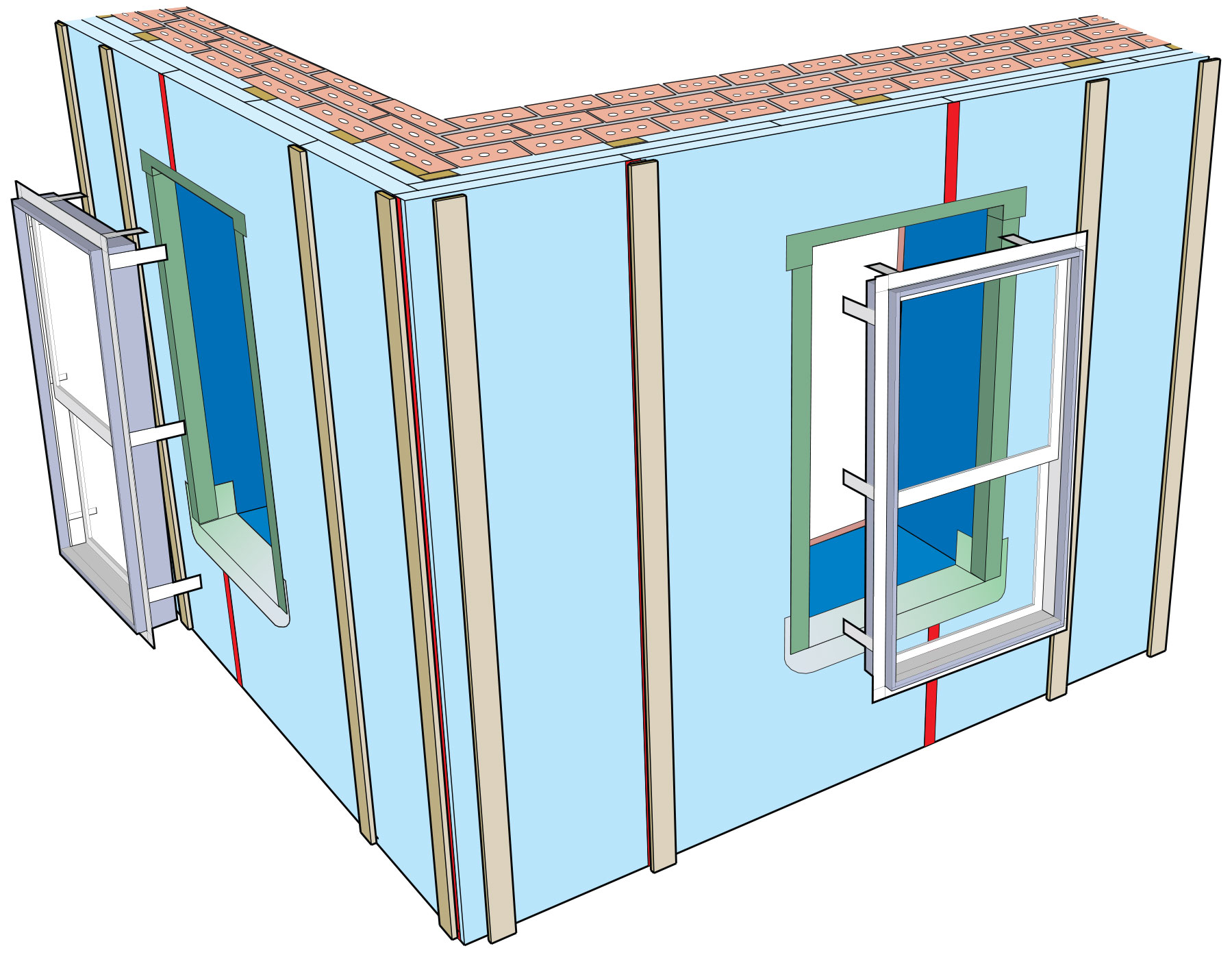
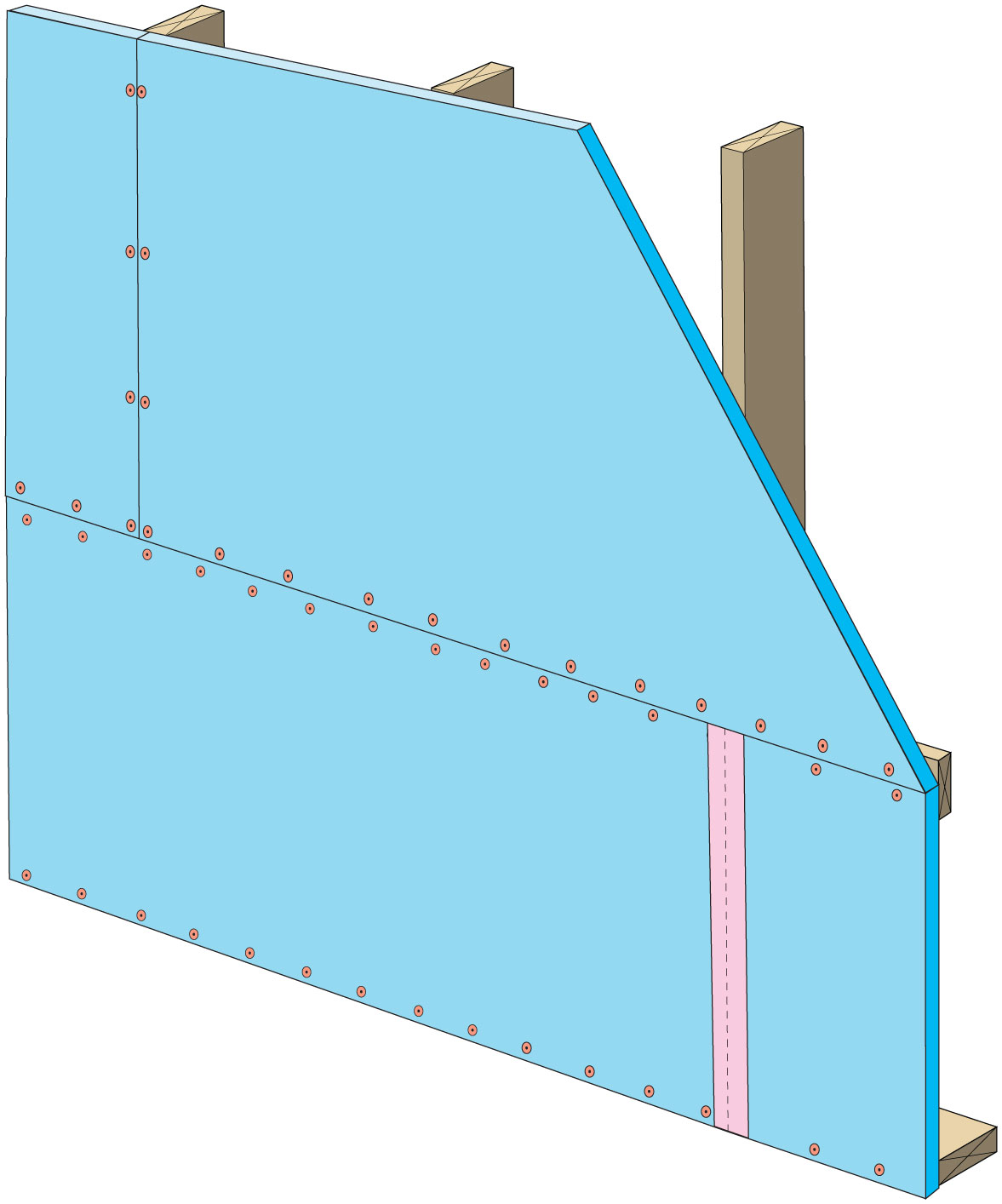
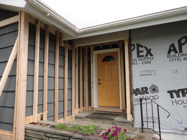
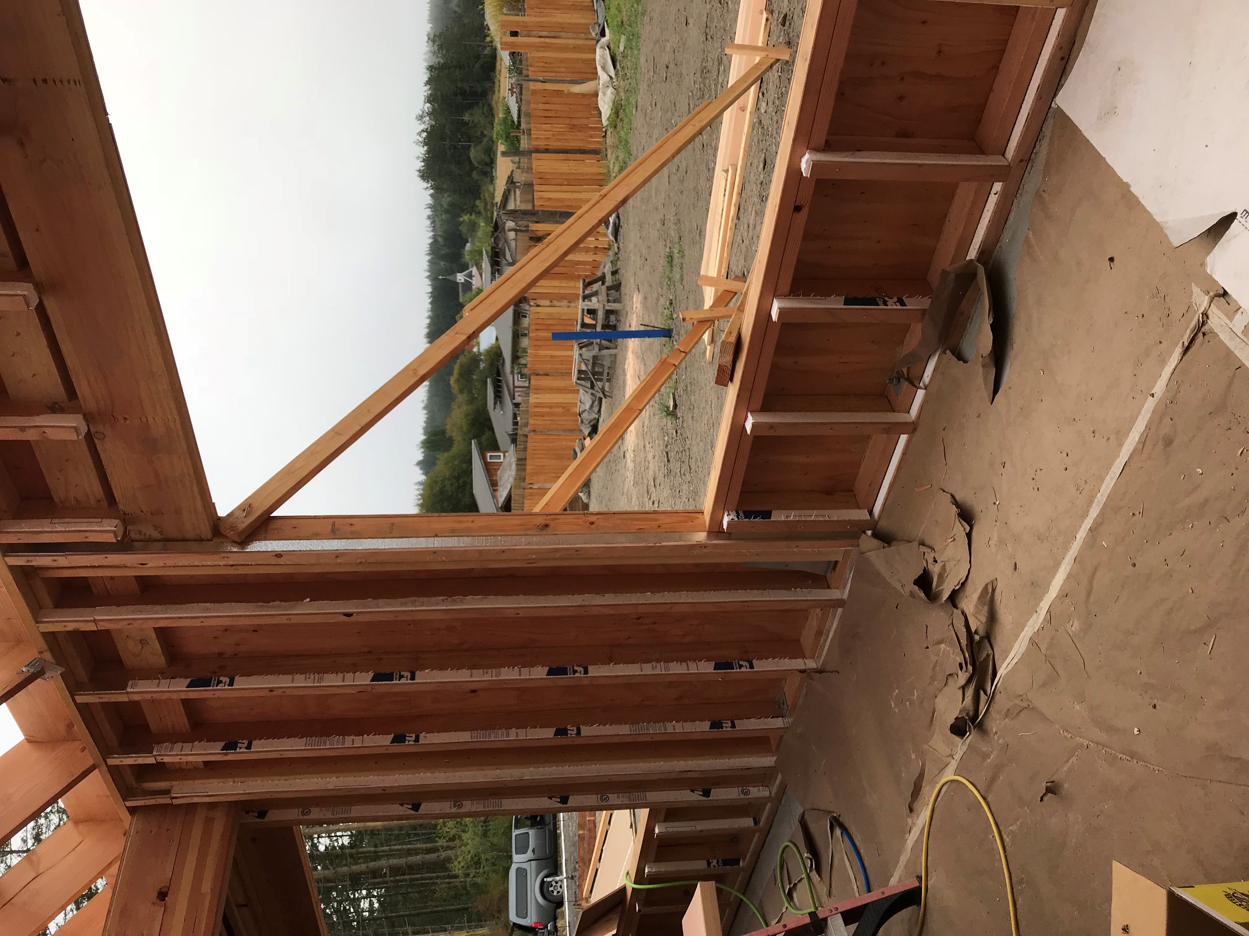
A flanged window unit is installed with straps that fasten to the interior surfaces of the plywood extension box; furring strips on each side of the window will be attached after the flanged window is installed and flashed
Image
A flow grid is inserted into the filter grille/slot to directly measure airflow.
Image
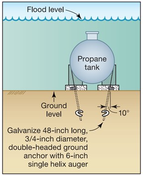
A fuel tank should be anchored with ground anchors designed for site conditions to maintain secure connection to its base in a flood or earthquake
Image
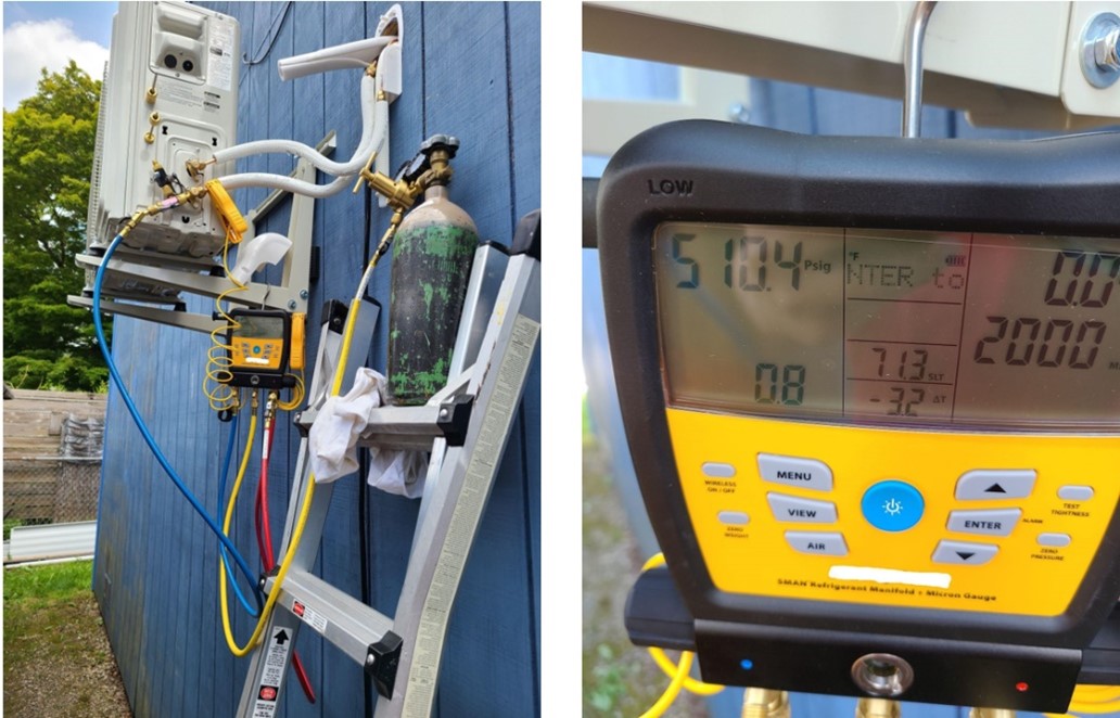
A nitrogen pressure test was completed on this ductless mini-split heat pump using a digital manifold gauge.
Image
Image
Image
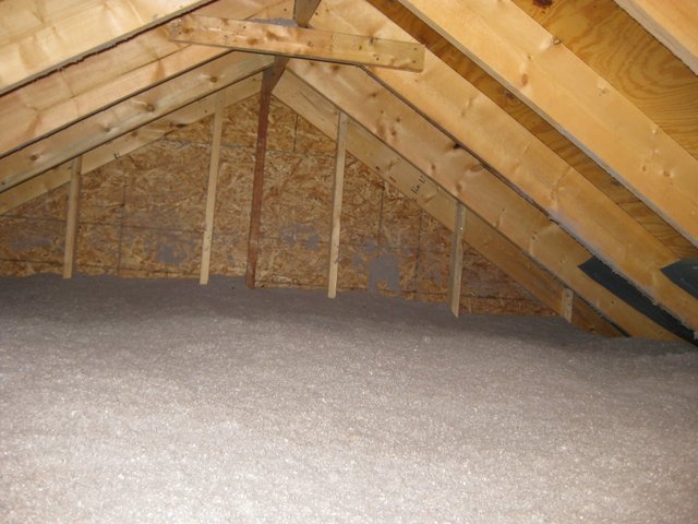
A simple vented attic with good air-sealing of the drywall ceiling air barrier, air flow from soffit vents to ridge vents protected by ventilation baffles, and lots of insulation covering the attic floor is unlikely to encourage ice dams.
Image
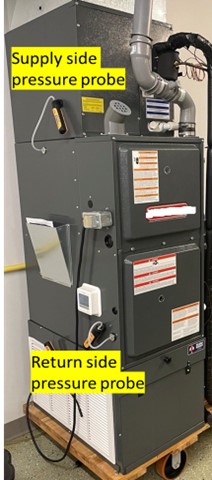
A static pressure measurement is taken on this air handler using probes on the supply and return sides of the fan.
Image
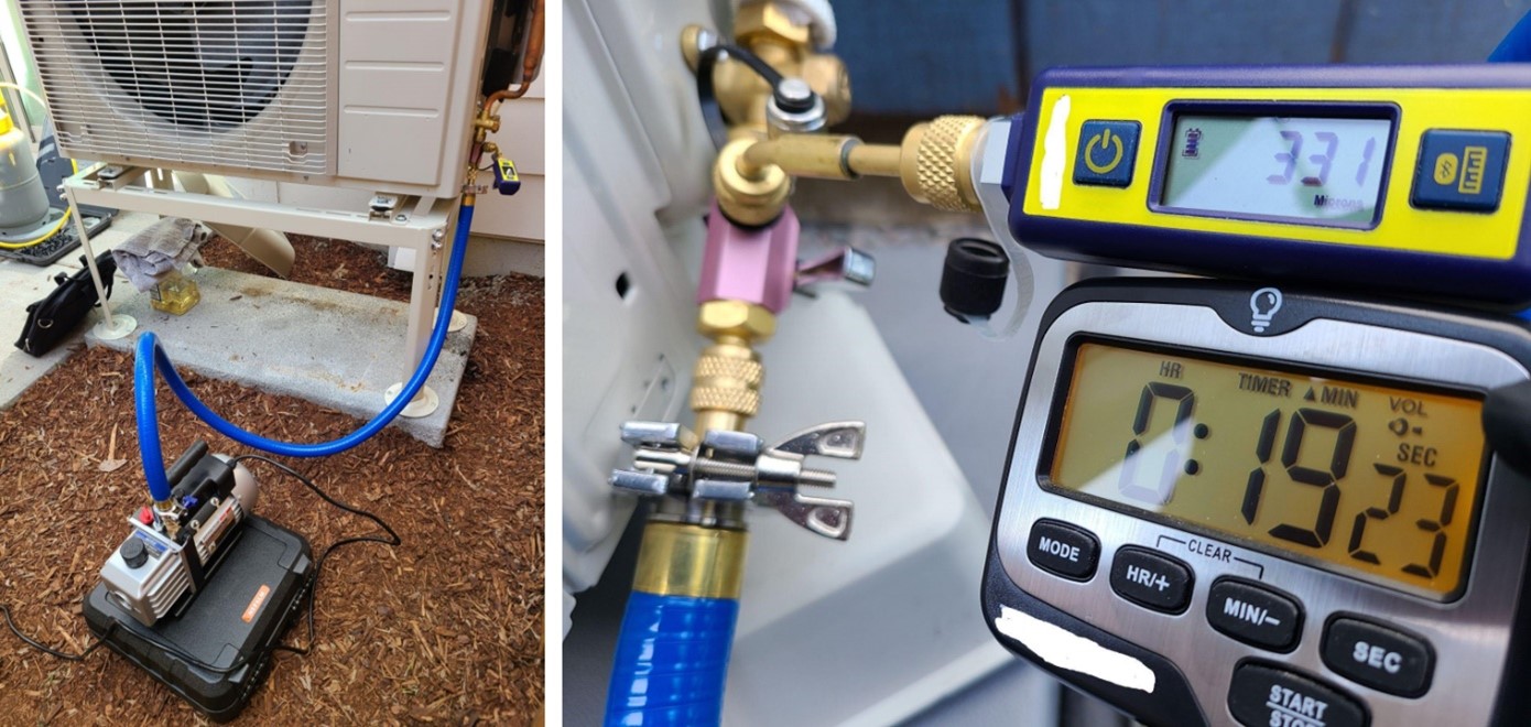
A vacuum decay test is performed on this ductless mini-split heat pump using a digital micron gauge for accurate measurement; a deep vacuum is achieved quickly by using large diameter, vacuum-rated hoses, and removing valve cores
Image
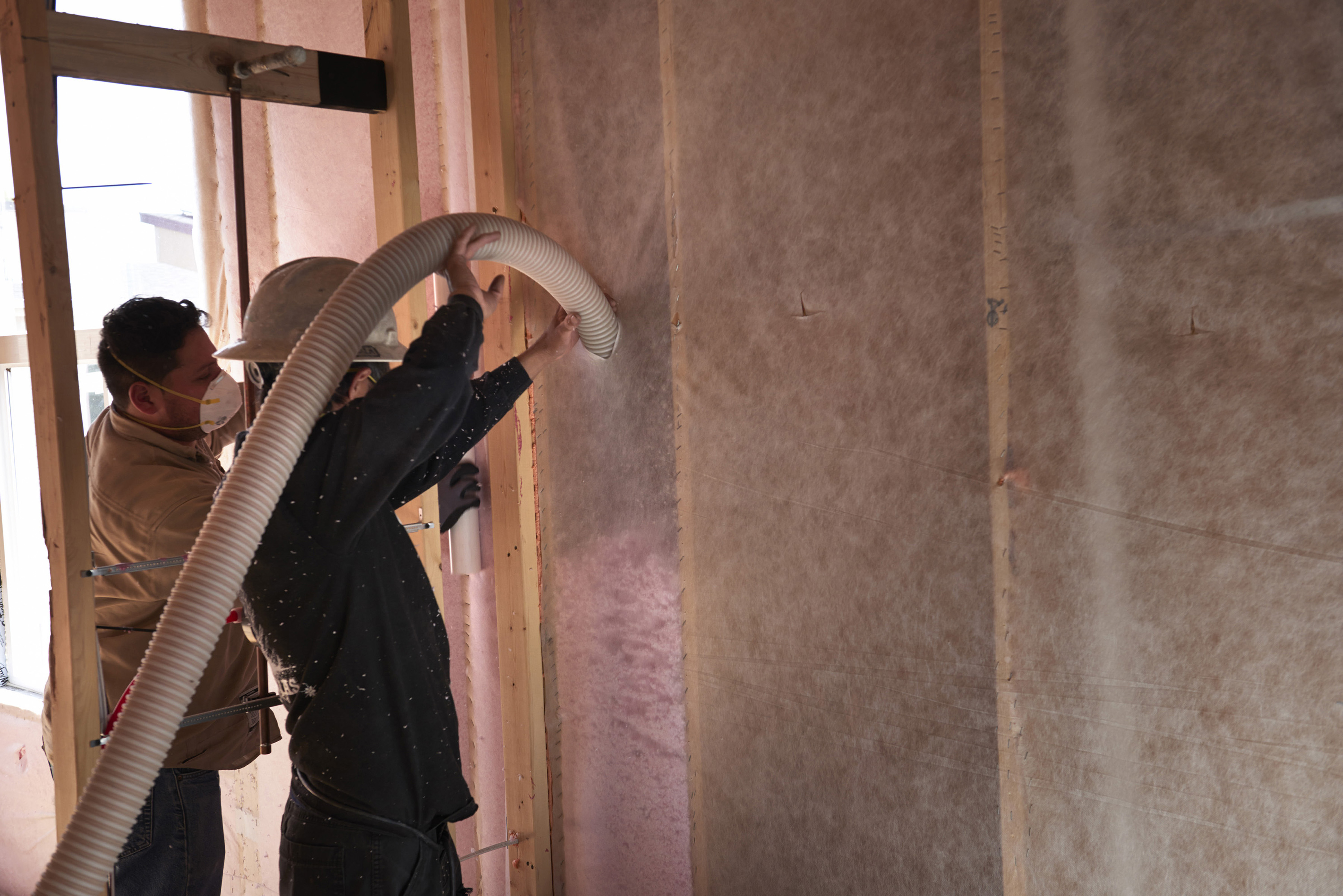
After attaching netting to the 2x6 studs, workers fill the wall cavities with R-23 of blown fiberglass made from recycled bottles.
Image
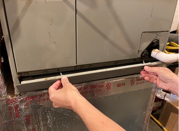
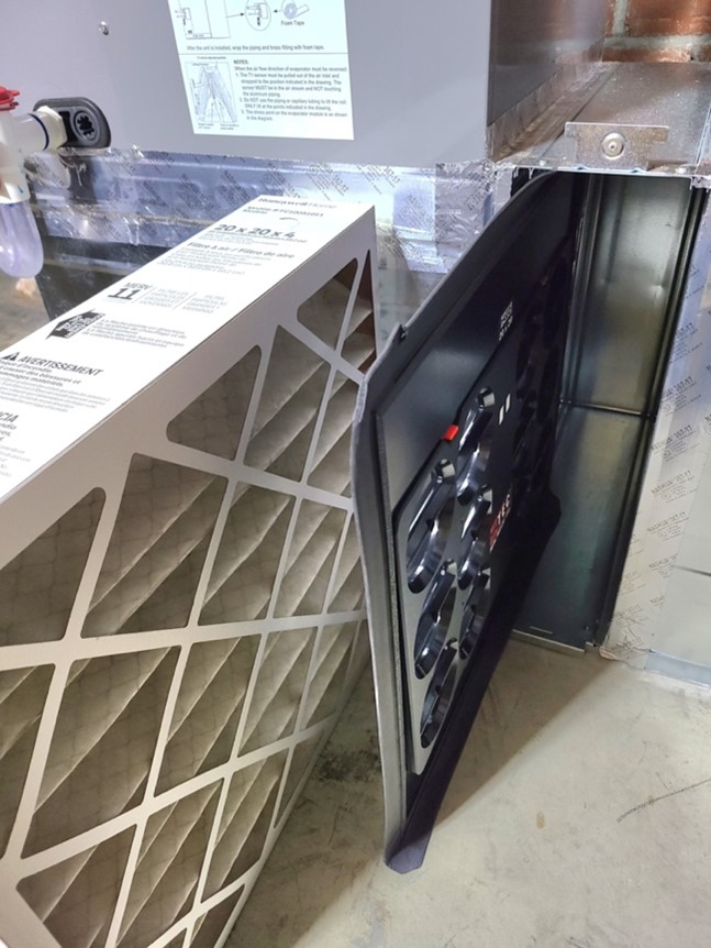
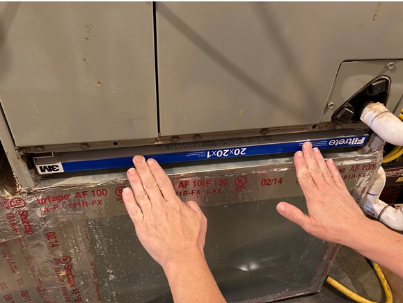
After inserting the new filter, replace the filter slot cover to minimize air leakage and heat loss.
Image
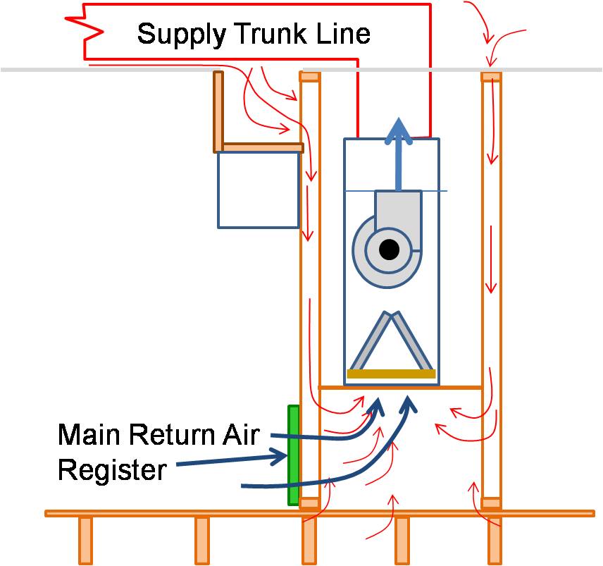
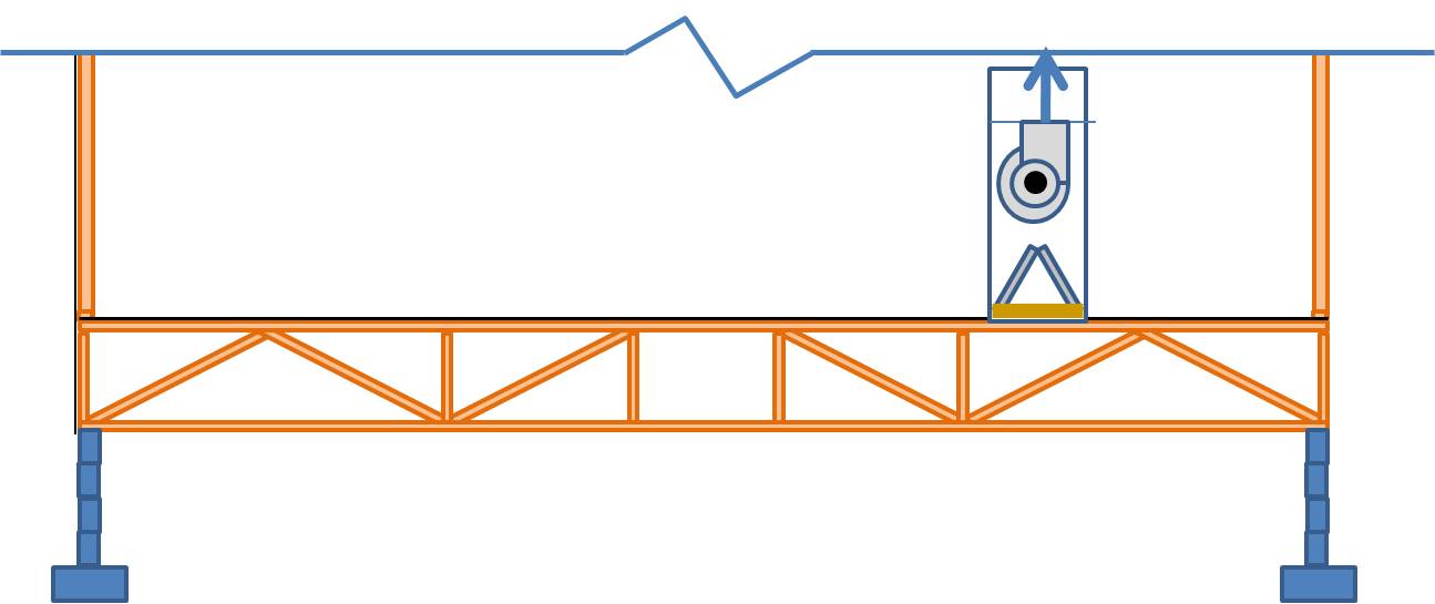
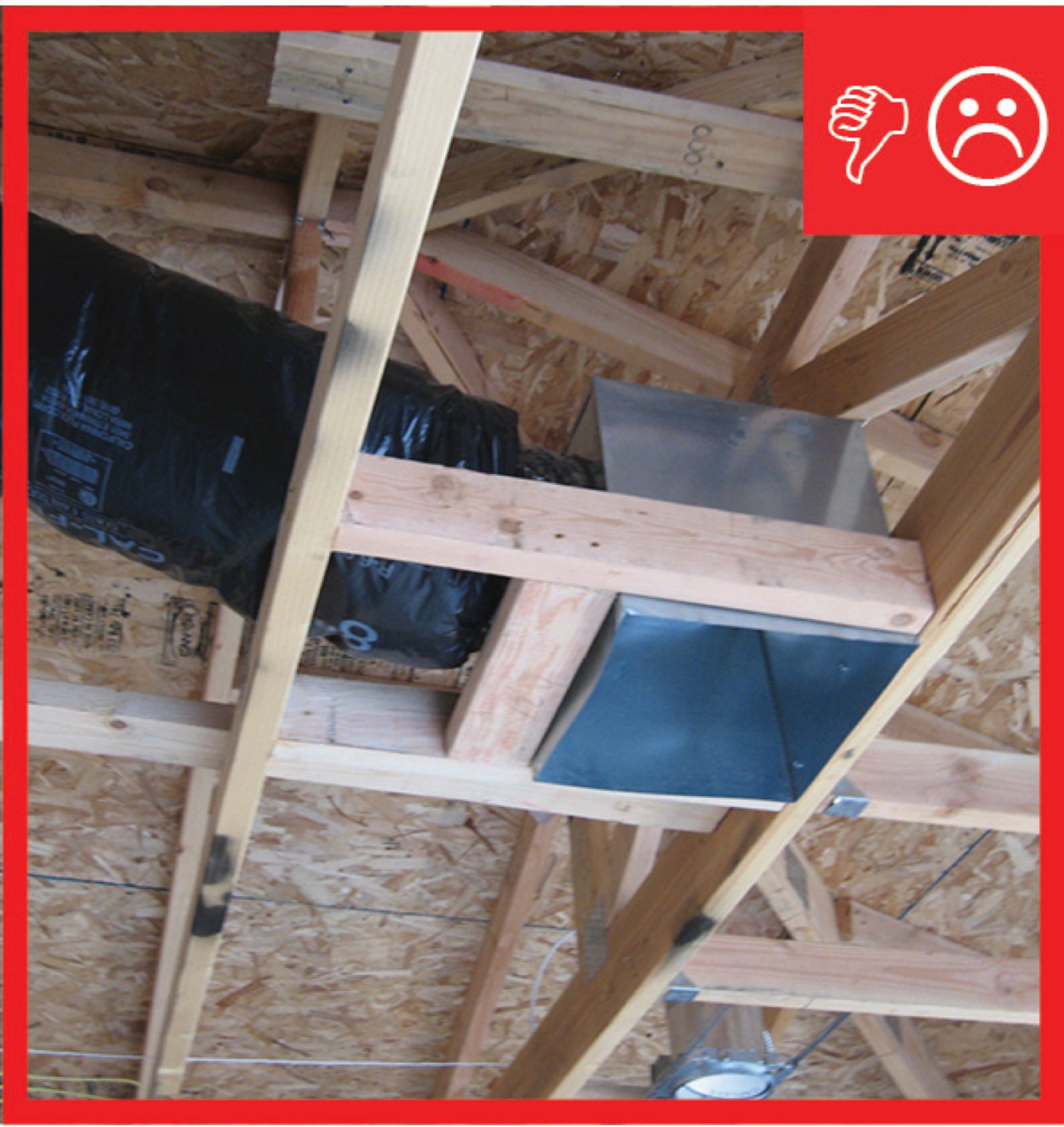
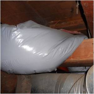
Air handler platforms used as return air plenums can draw air from vented attics and crawlspaces through other connected framing cavities
Image
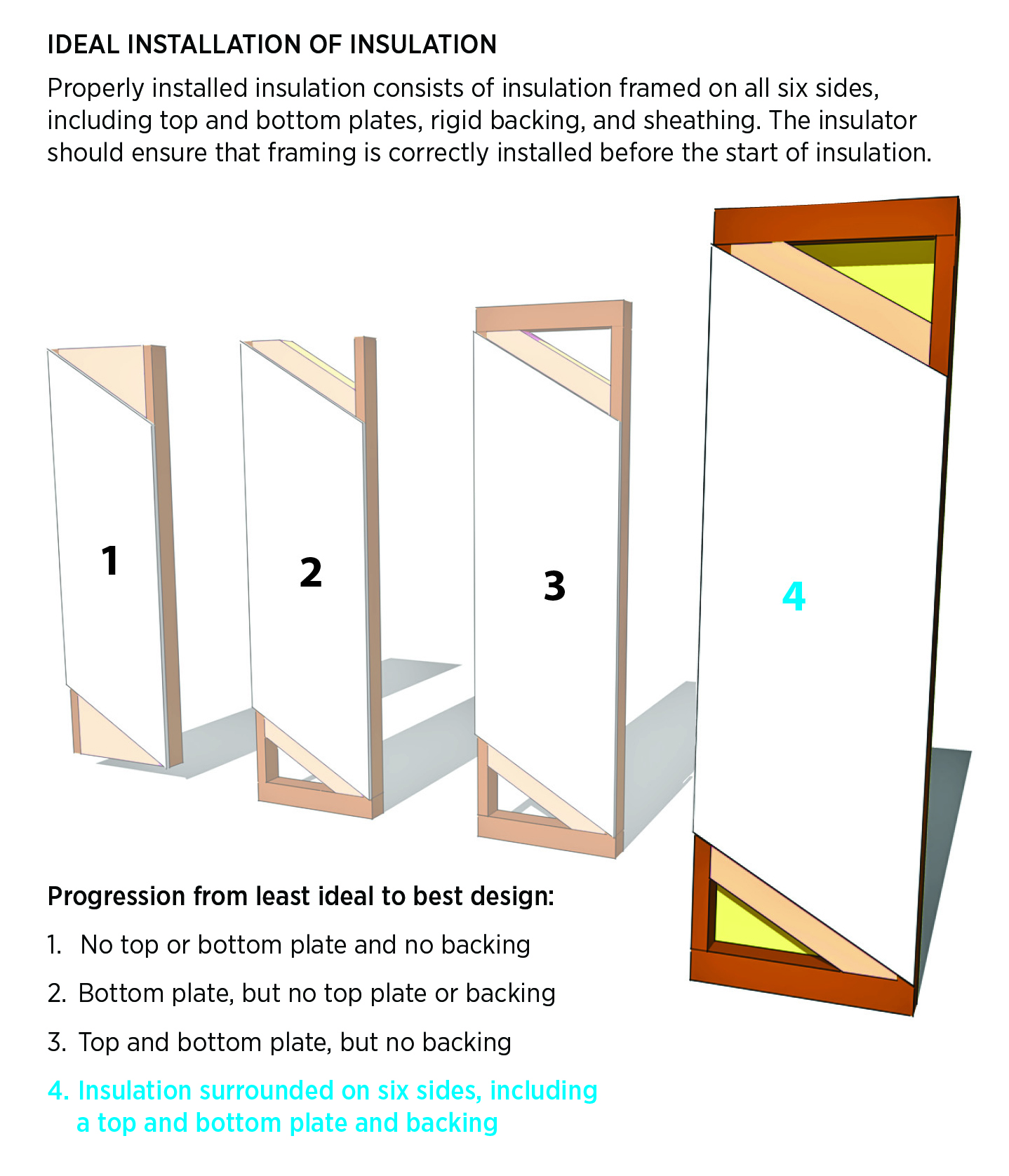
All ceiling, wall, floor, and slab insulation shall achieve RESNET-defined Grade I installation
Image
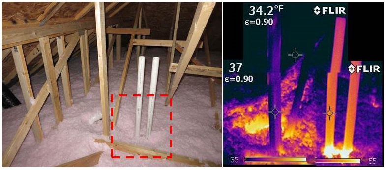
An IR camera image shows gaps around HVAC flue pipes allow conditioned air to leak through blown fiberglass into the attic
Image
Image
Image
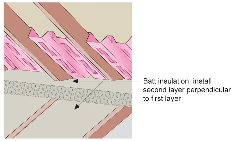
Batt insulation is installed in two layers in perpendicular directions against the baffle to full required insulation height
Image
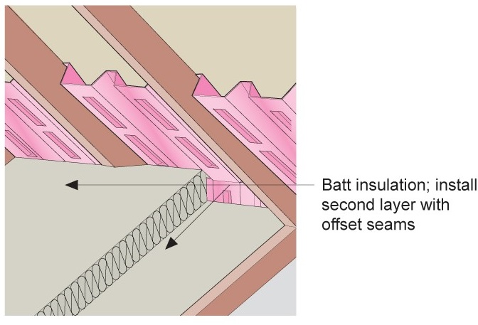
Batt insulation is installed in two layers with offset seams against the baffle to full code-required insulation height
Image
Batt insulation should be cut to fit around wiring so that insulation can completely fill the wall cavity
Image
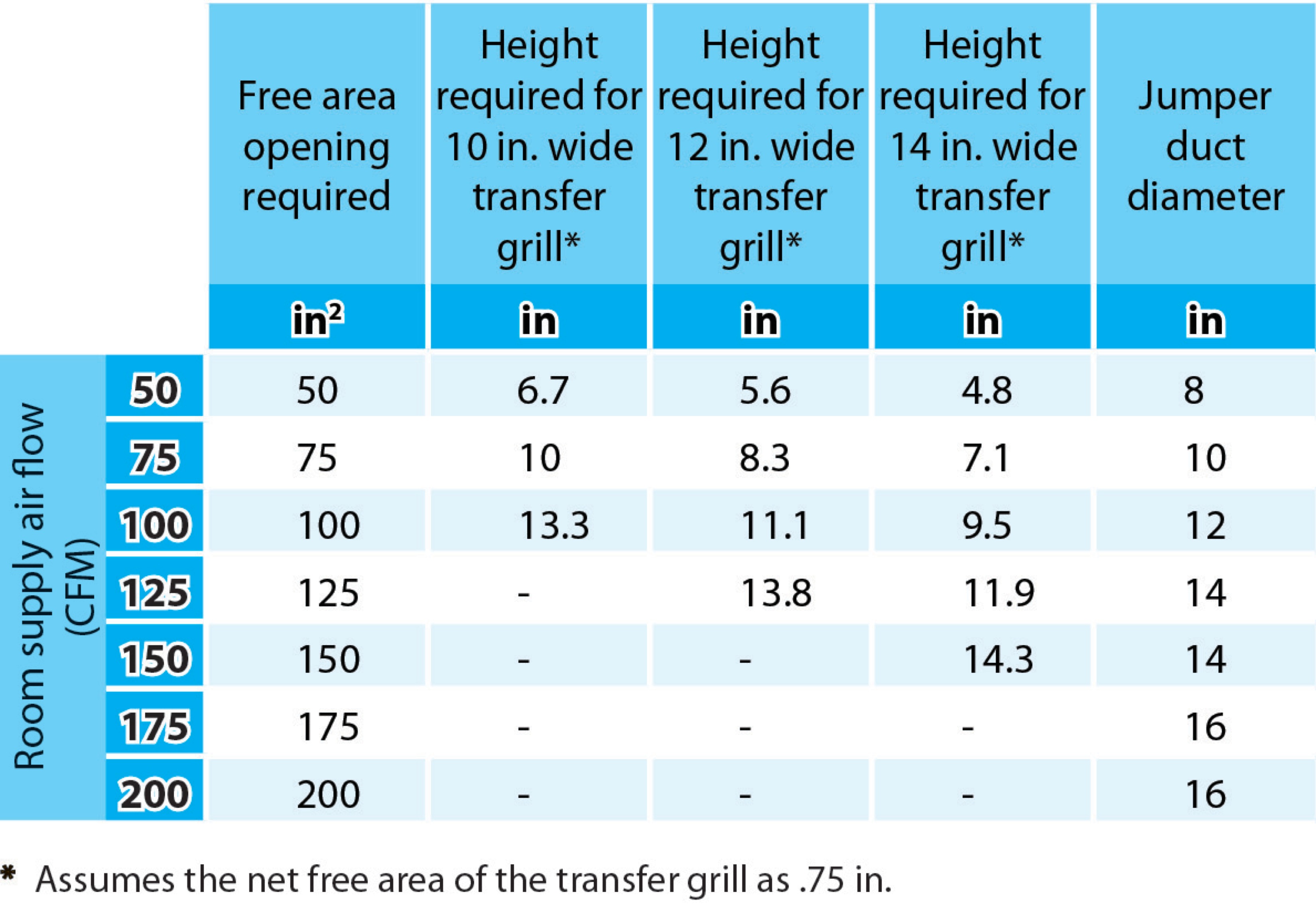
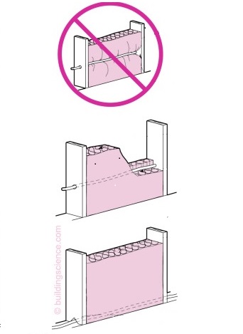
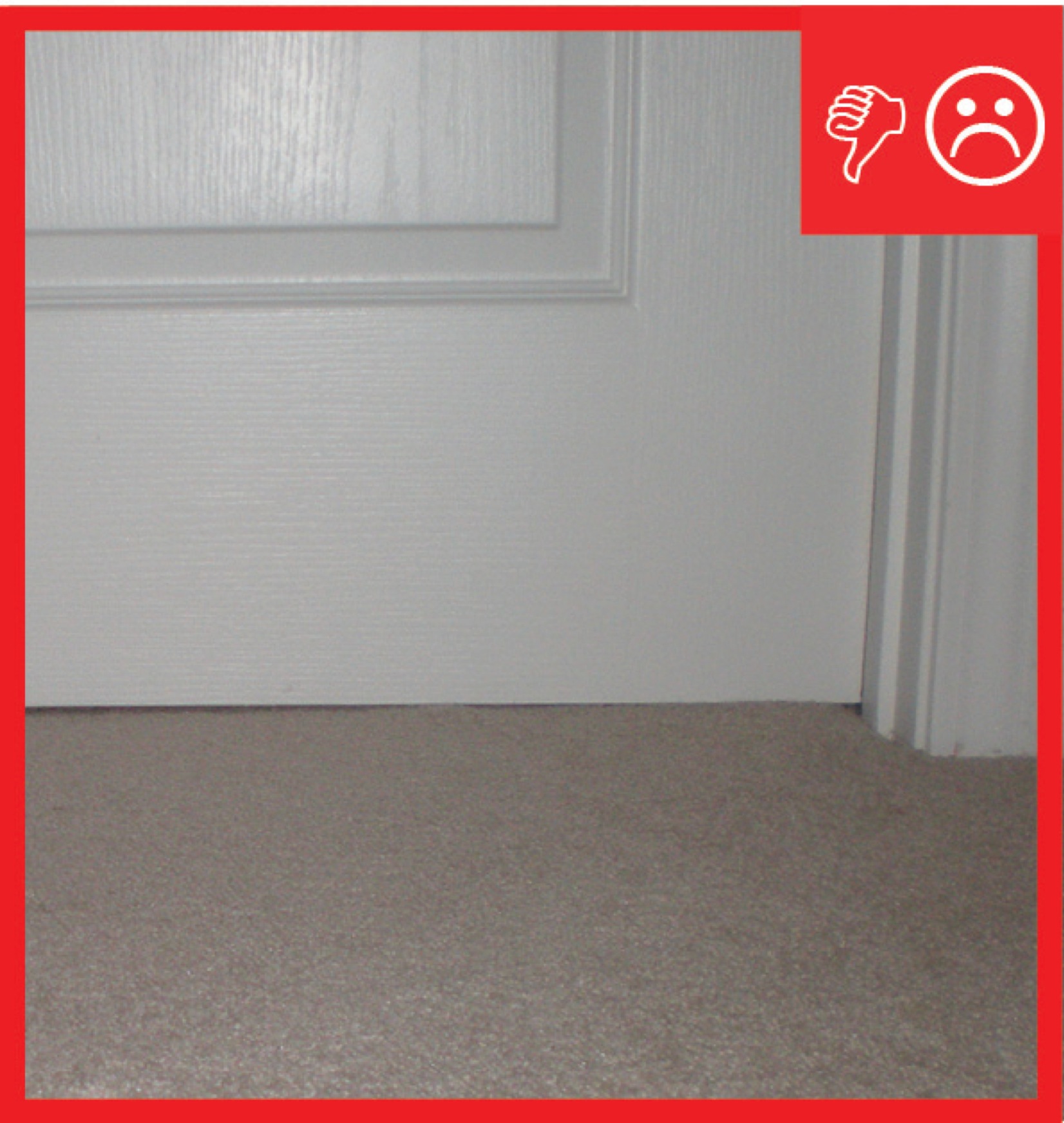
Bedrooms pressure-balanced and provide 1 sq. in. of free area opening per 1 CFM of supply air or achieve a Rater-measured pressure differential ≤ 3 Pa
Image

Bedrooms pressure-balanced and provide 1 sq. in. of free area opening per 1 CFM of supply air or achieve a Rater-measured pressure differential ≤ 3 Pa
Image

Blown cellulose insulation completely fills the netted wall and ceiling cavities.
Image

Image
Building cavities not used as supply or return ducts unless they meet Items 3.2, 3.3, 4.1, and 4.2 of this Checklist
Image
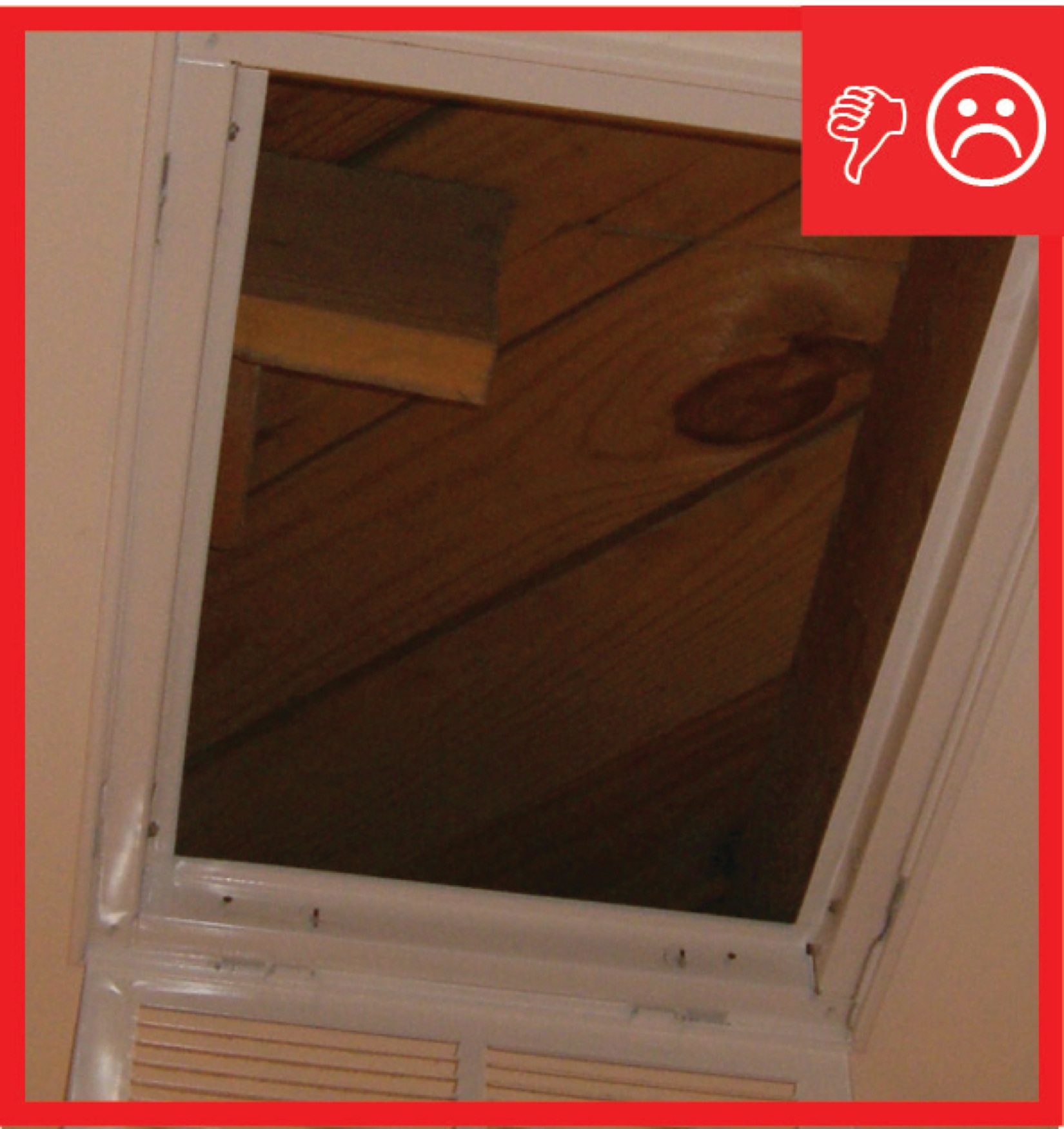
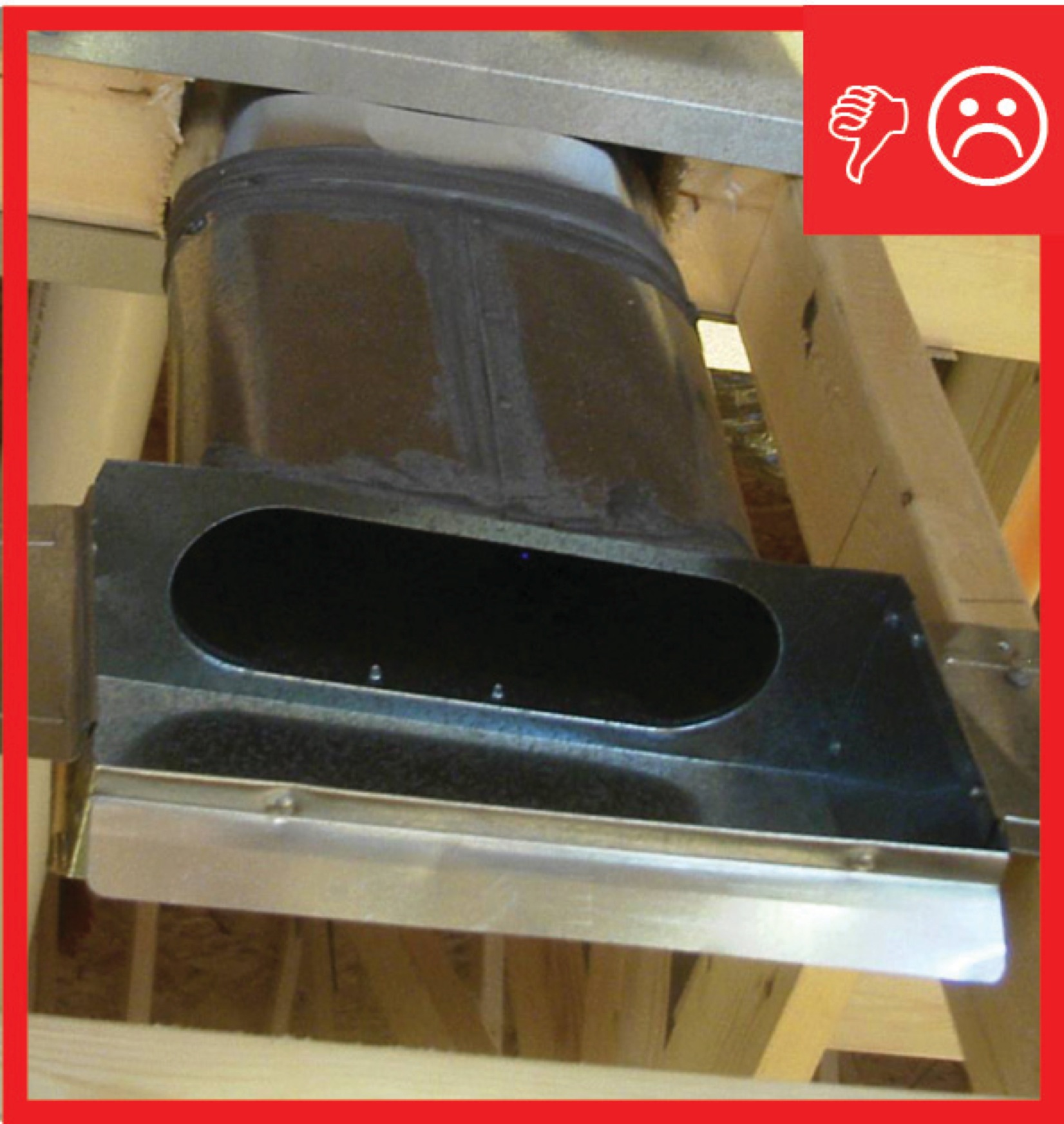
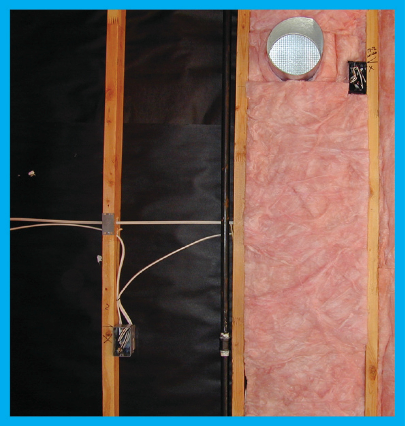
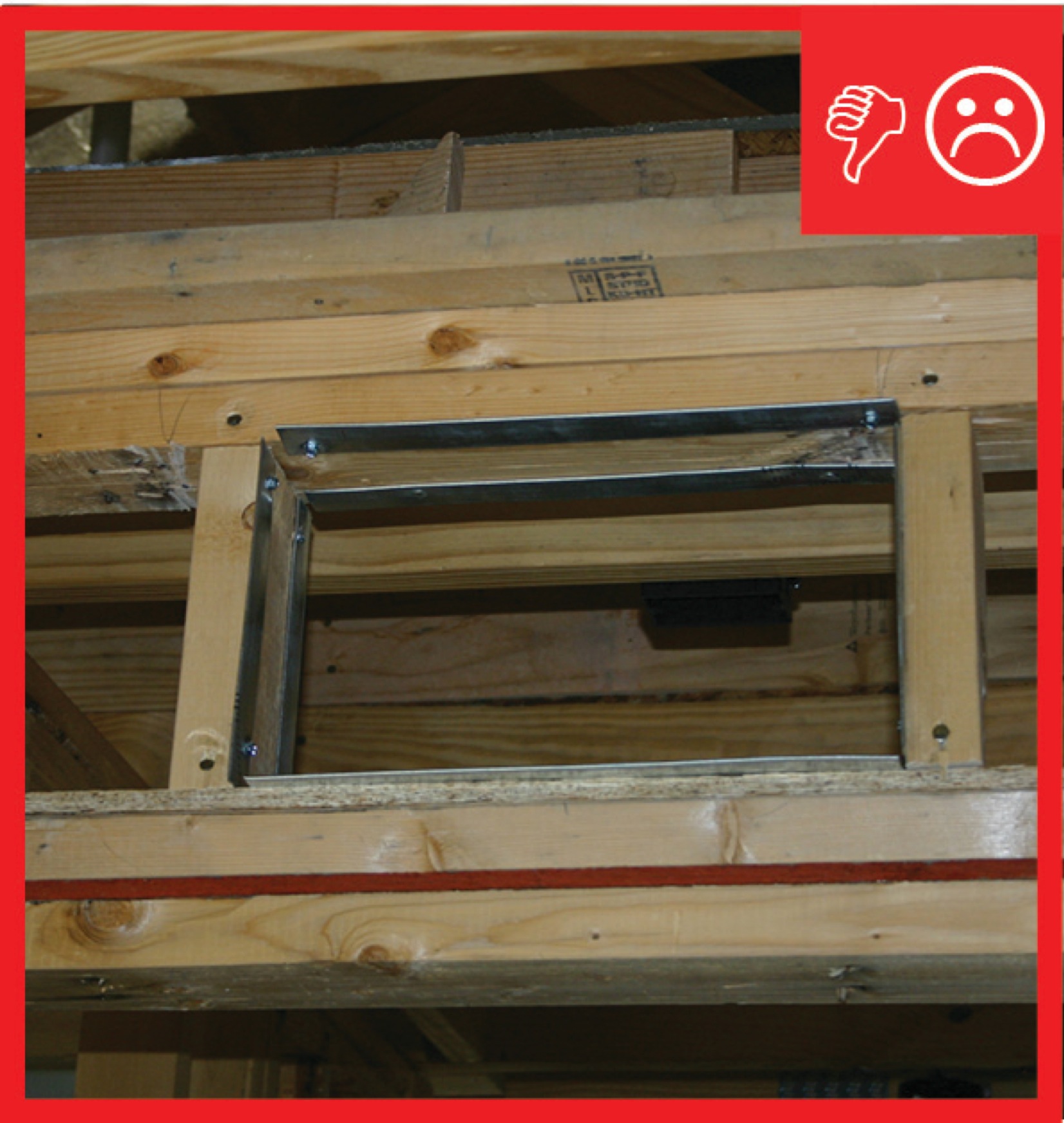
Cavity used for return is not insulated and is not air sealed, which will pull in air from outside
Image
Image
Ceiling, wall, floor, and slab insulation levels shall meet or exceed Builders Challenge levels
Image
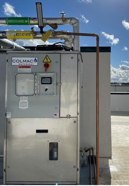
Central heat pump water heaters like this fully packaged system provide efficient, reliable domestic hot water for multifamily buildings; storage tanks are within the enclosure, and the heat pump is seen just outside.
Image
Clean taping areas and install 3" tape on vertical joint of upper insulation overlapping the horizontal joint
Image
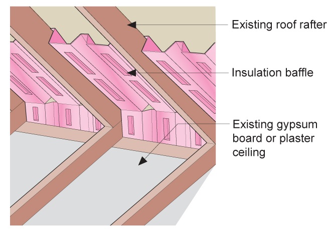
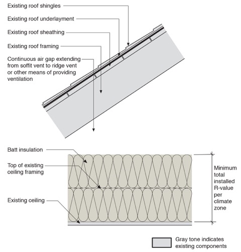
Clean the attic floor of debris prior to installing new attic insulation. Use baffles to provide a path for ventilation air entering the attic from the soffit vents
Image
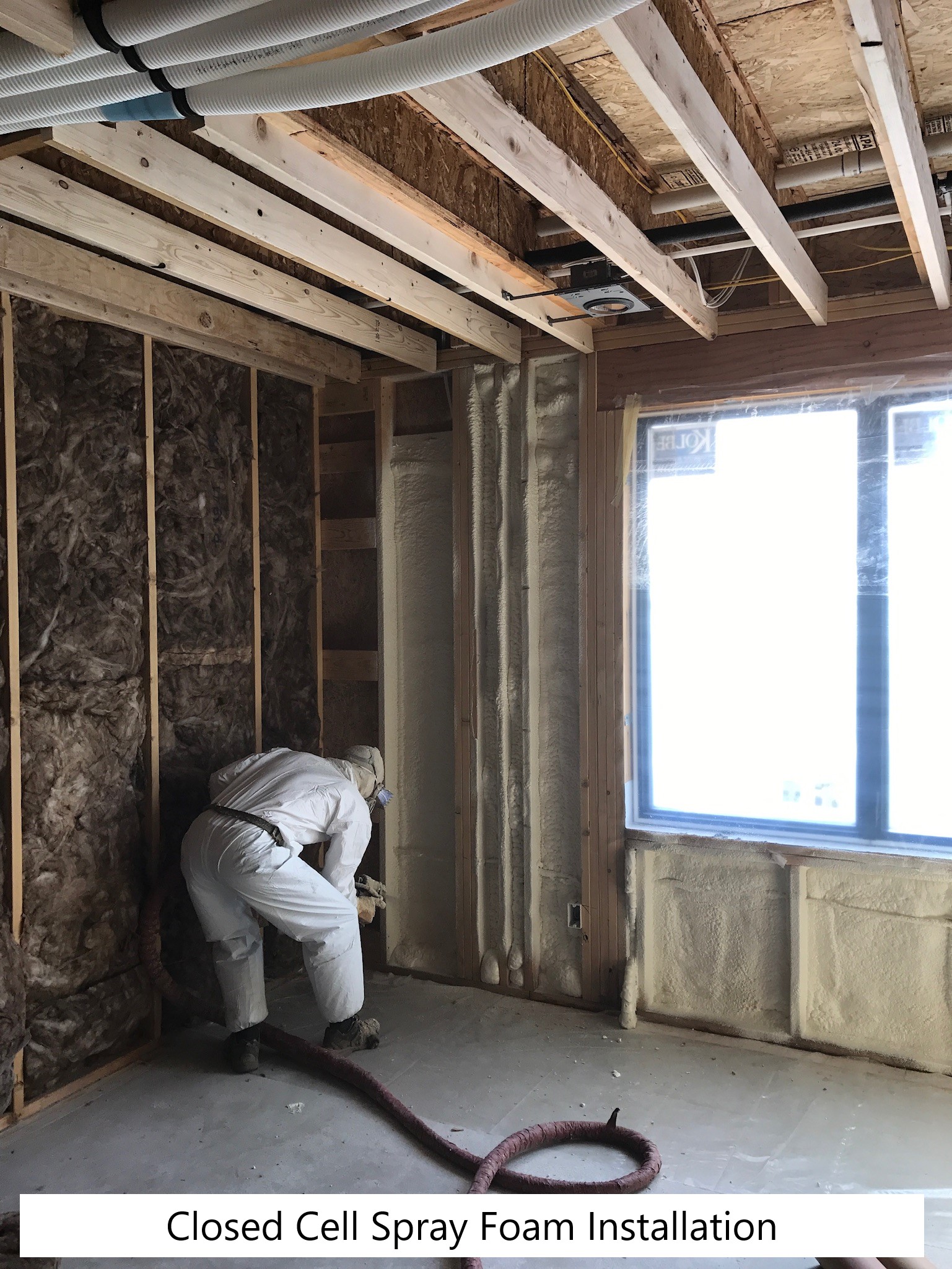
Closed-cell spray foam insulation covers the attic floor to provide a continuous air control layer.
Image
Image
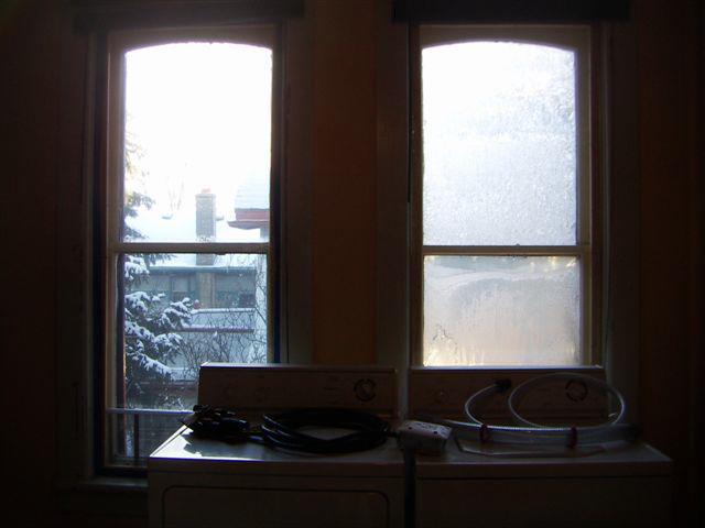
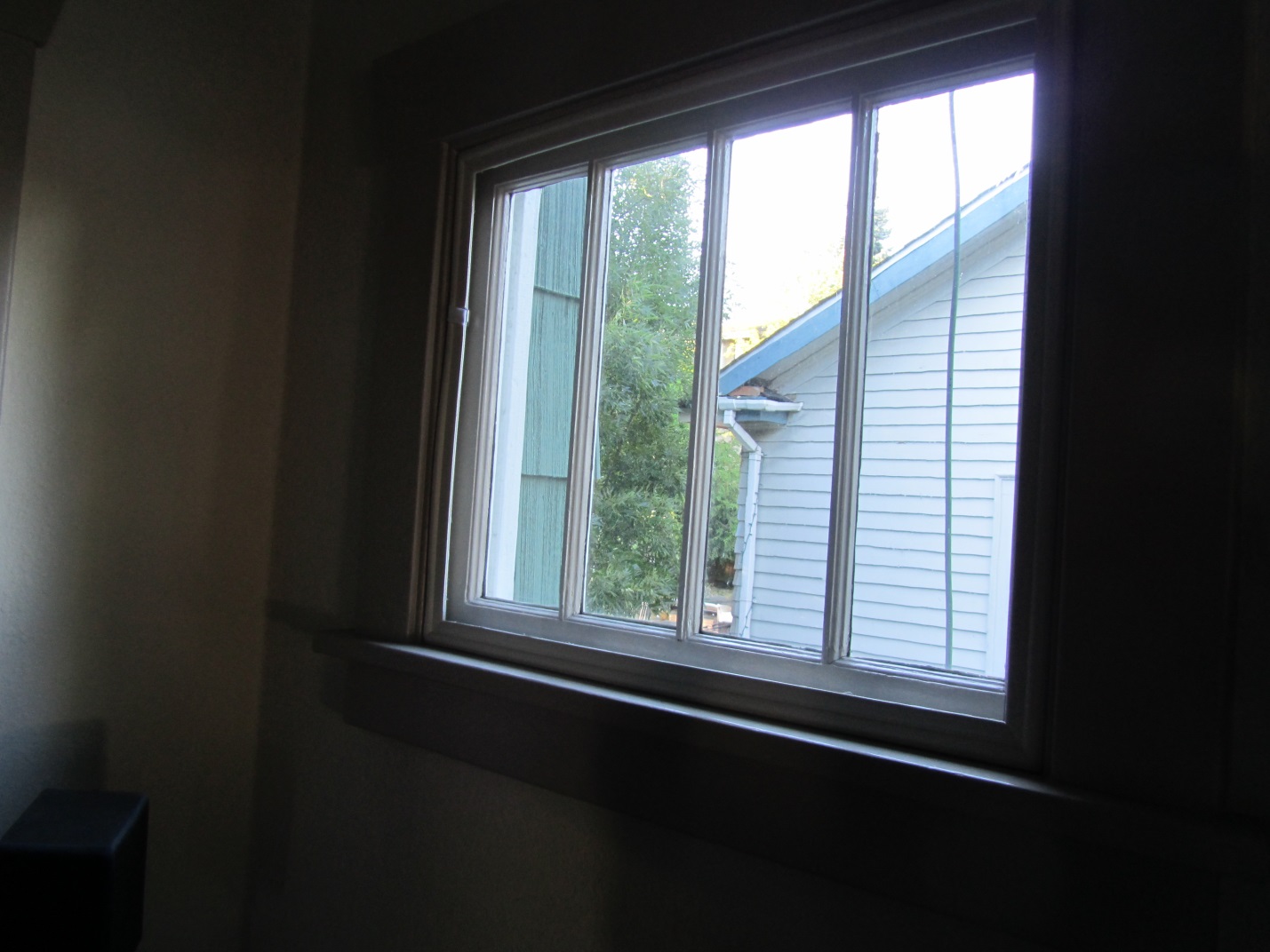
Condensation can form between the interior removable storm window and the existing window if the storm window is not air tight
Image

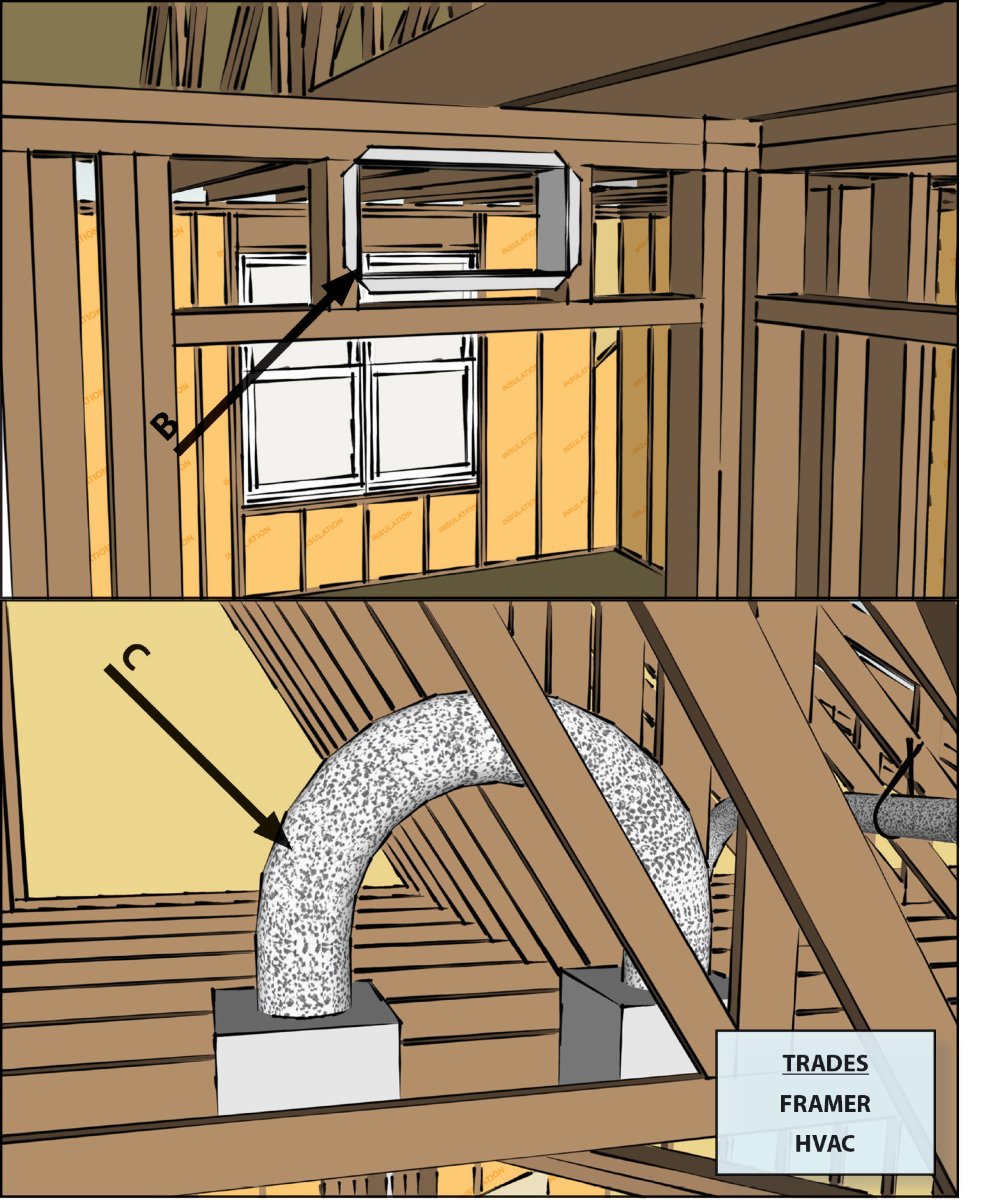
Consider using a metal duct elbow instead of flex duct at boot connections to prevent compressions
Image
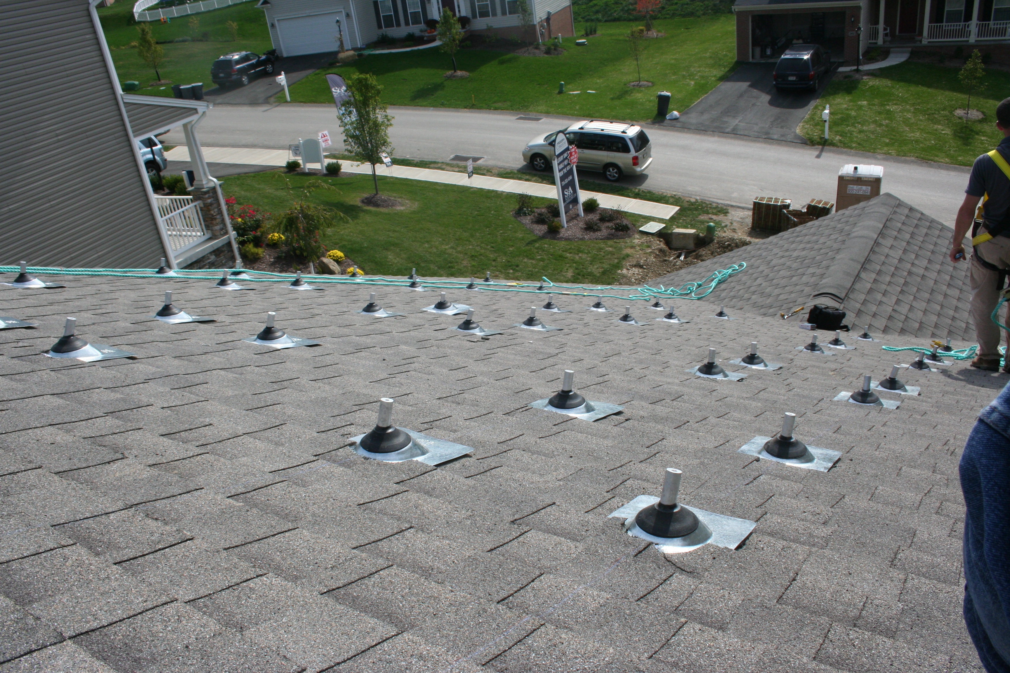
Contractors install gasket between the second-story top plate and the rim joist to air seal at this wall to attic transition (Source: S&A Homes).
Image
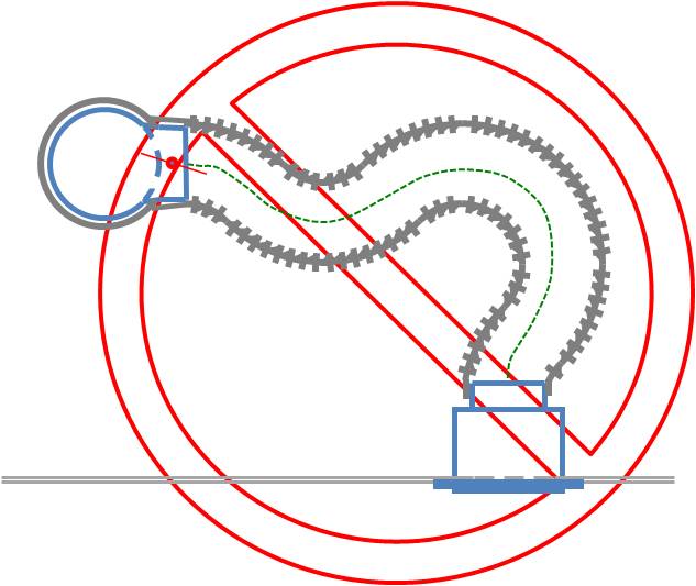
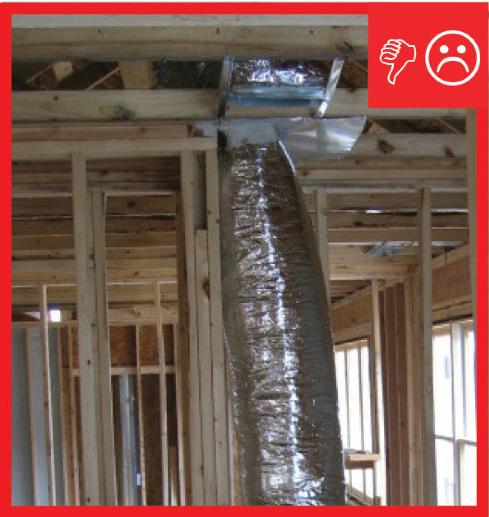
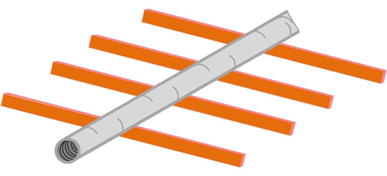
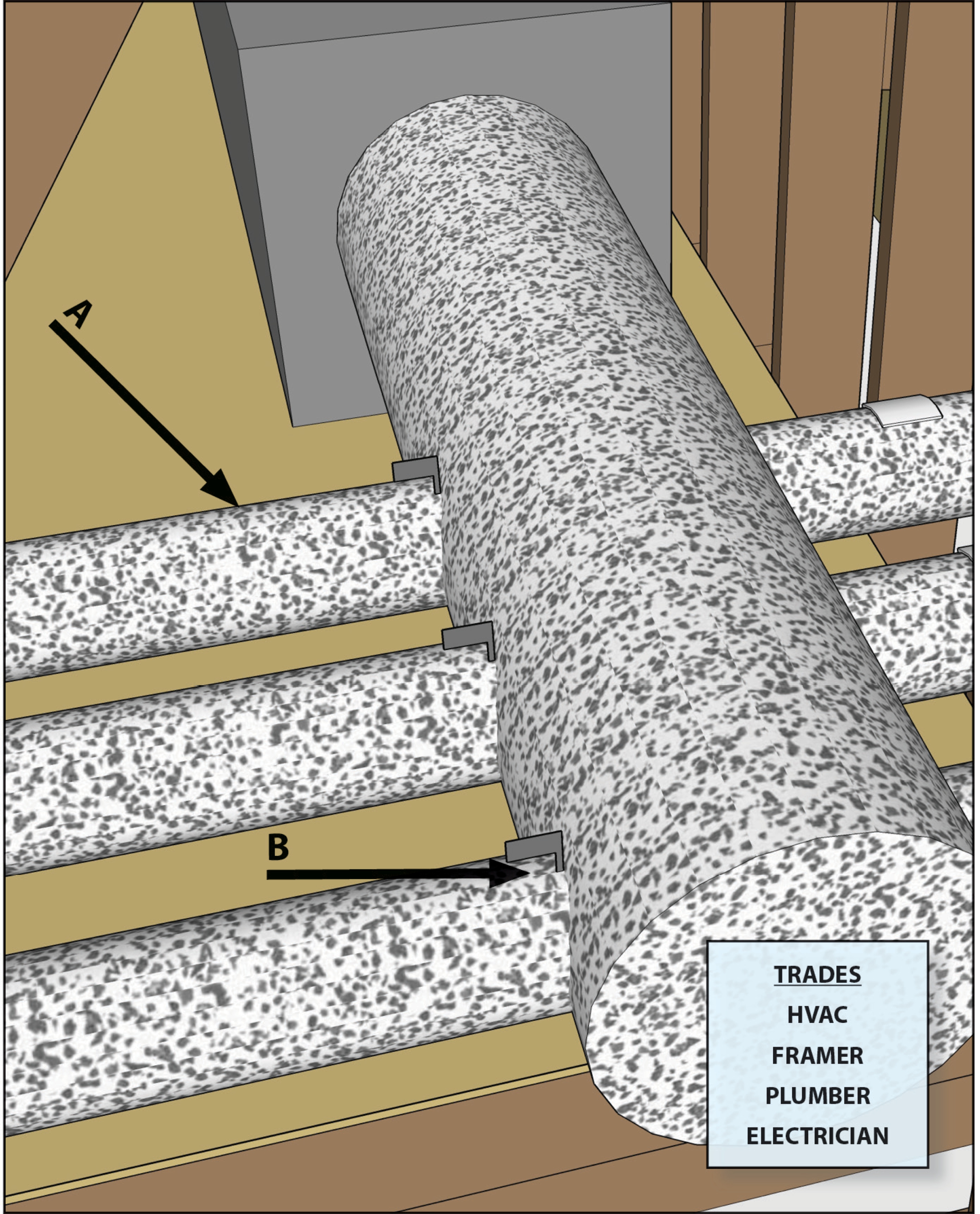
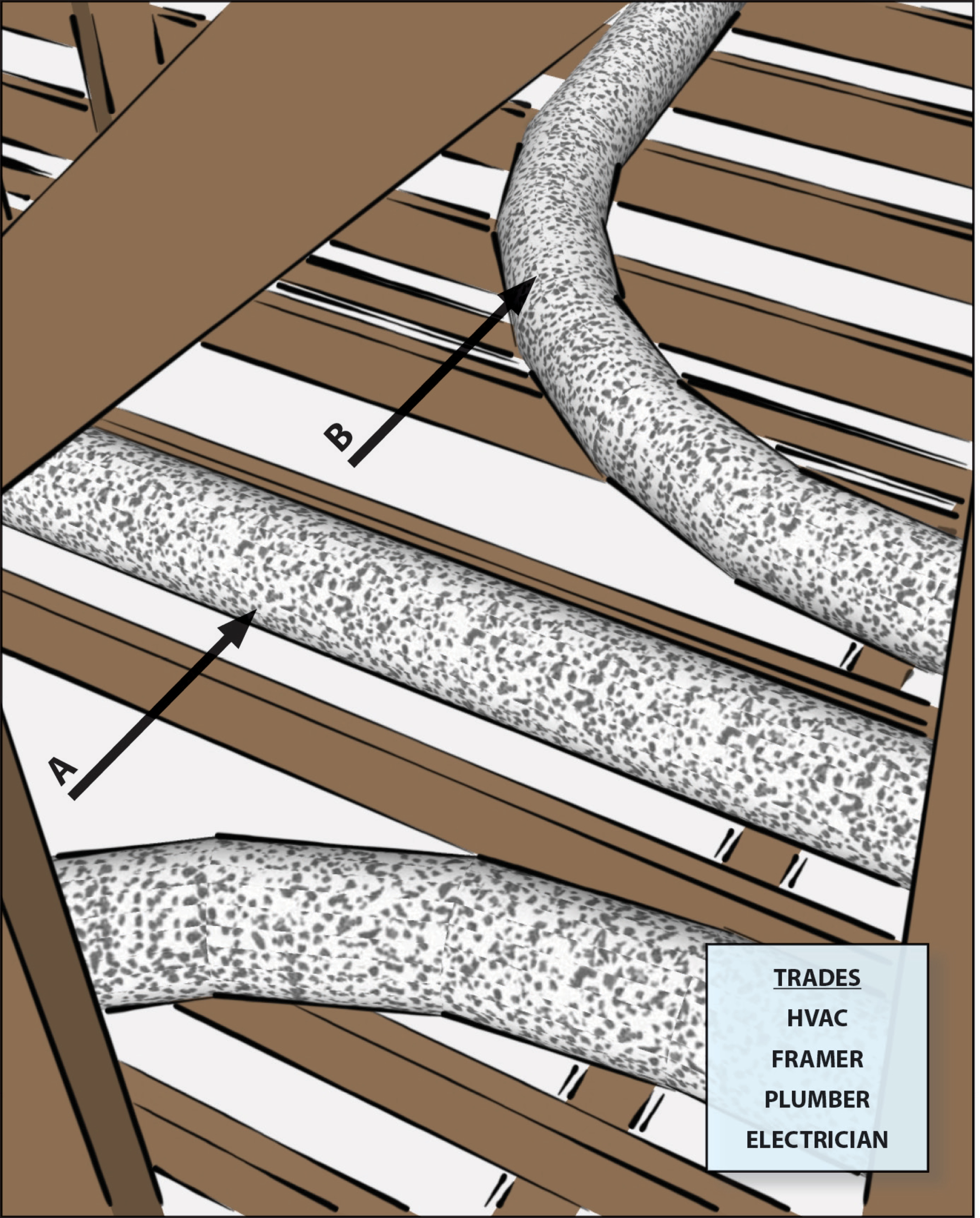
Coordinate with other trades including framers, plumbers, and electricians to prevent needless looping of flex duct
Image
Image
Deep energy retrofit showing insulation sprayed on exterior of walls over existing siding
Image
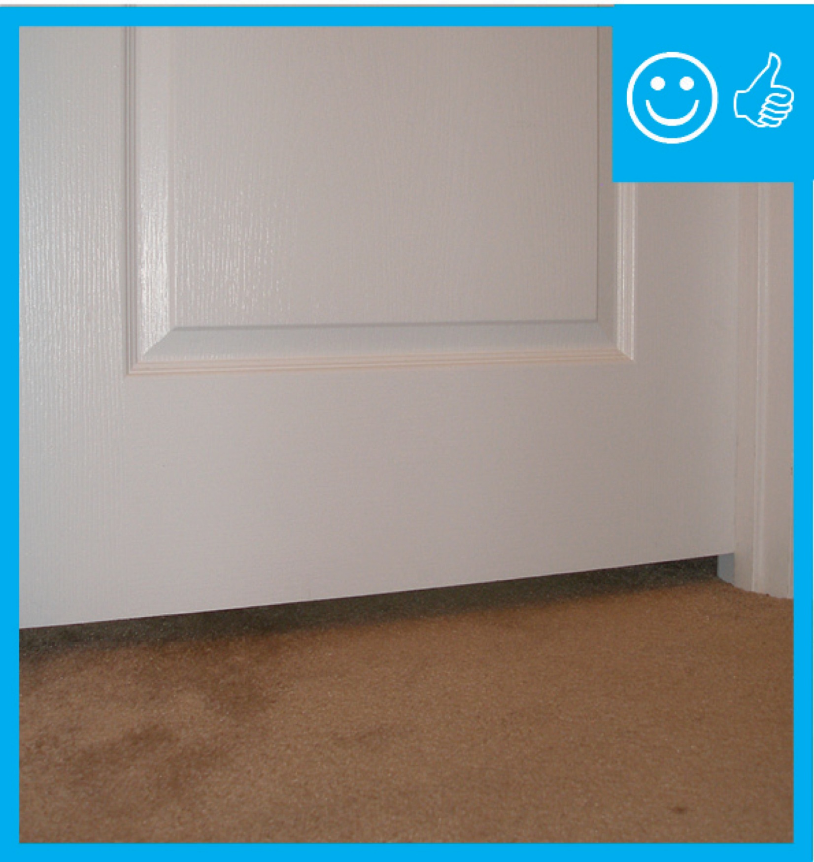
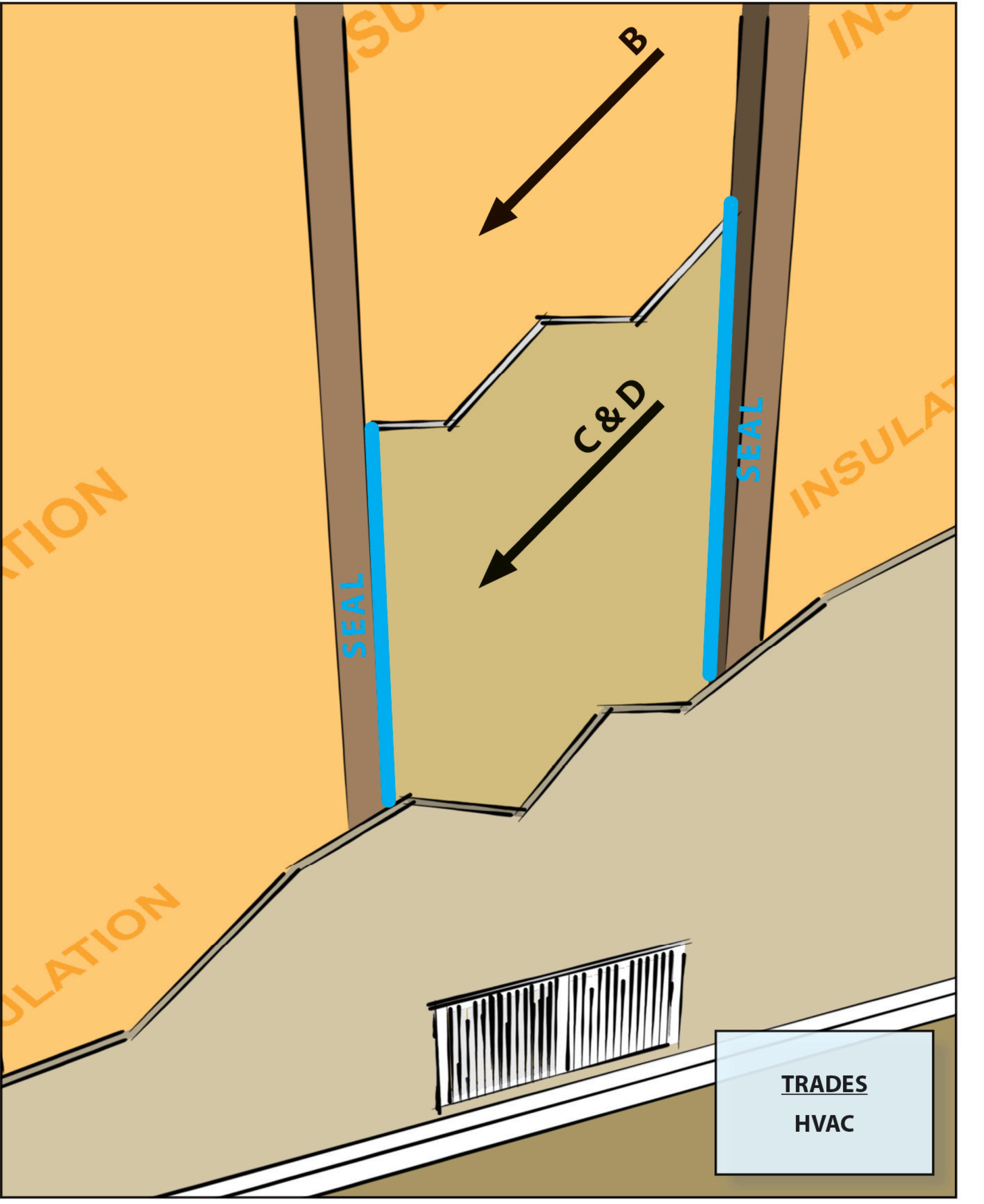
Door has been undercut to allow for specified amount of air flow therefore contributing to pressure balancing
Image
Image
Image
Image
Image
Image
Image
Image
Image
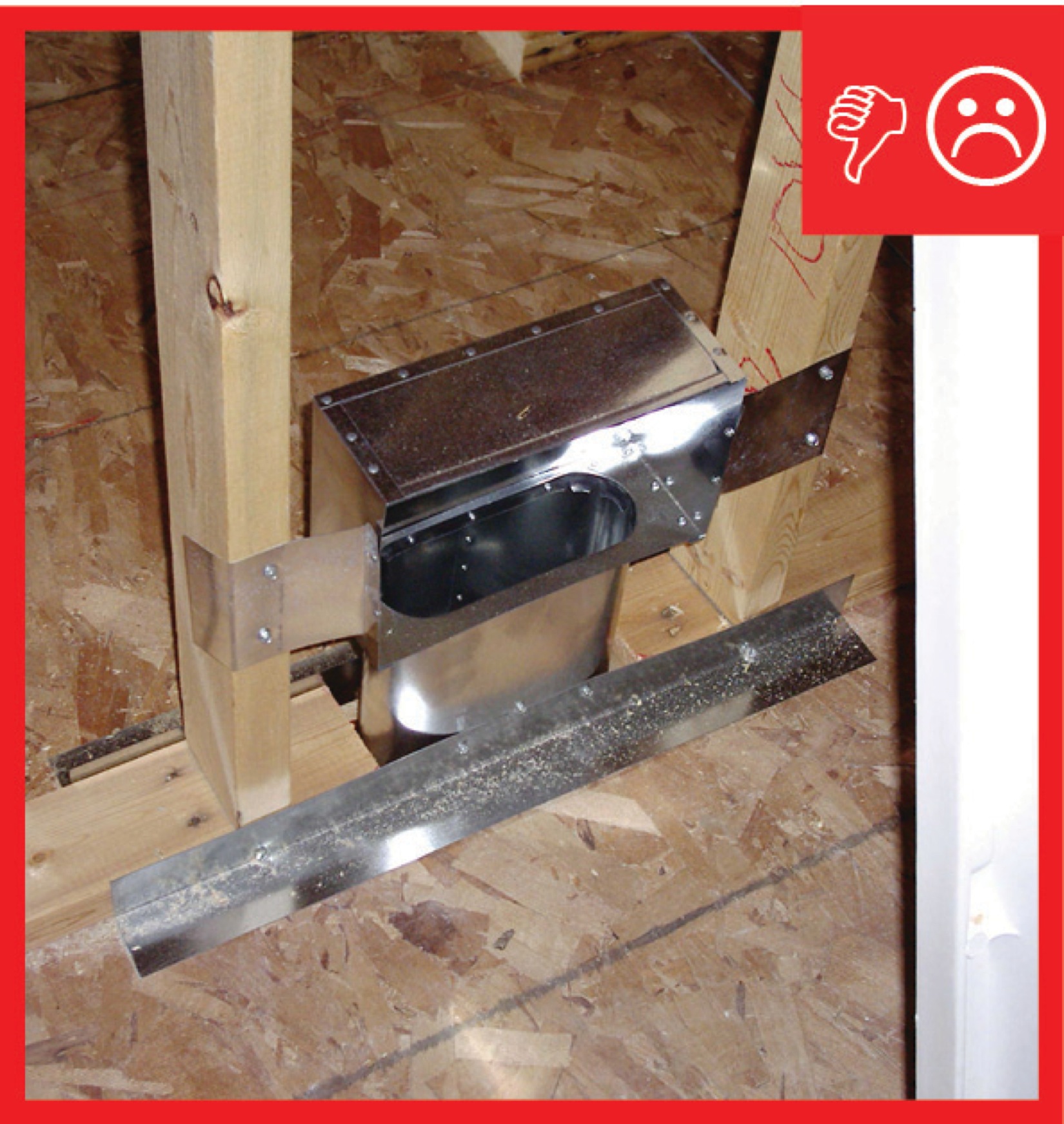
Duct to boot connection of jump duct not fastened and sealed
Image
Image
Image
Image
Image
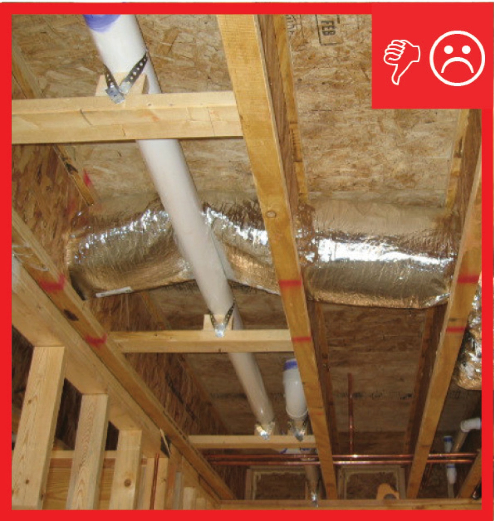
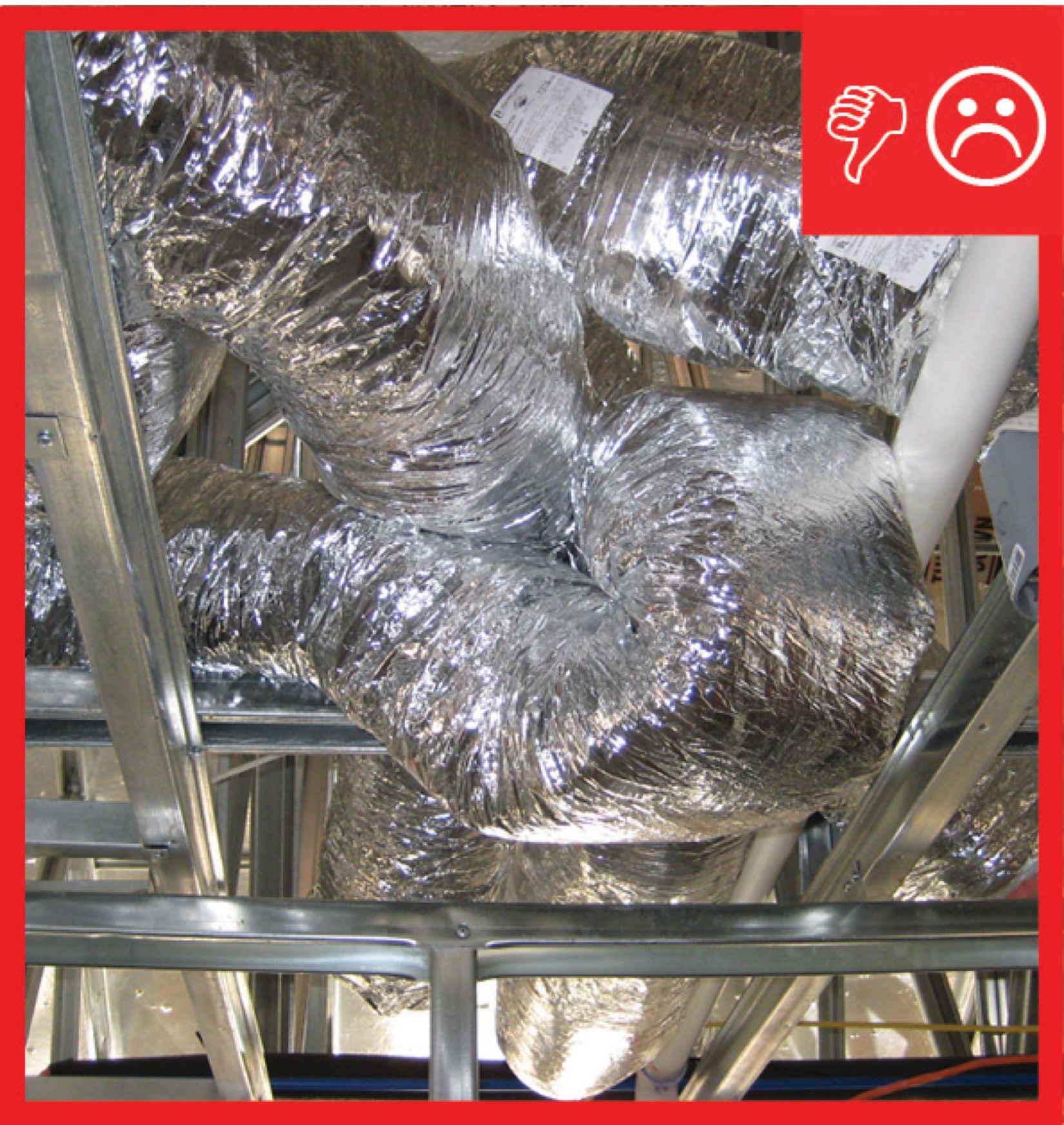
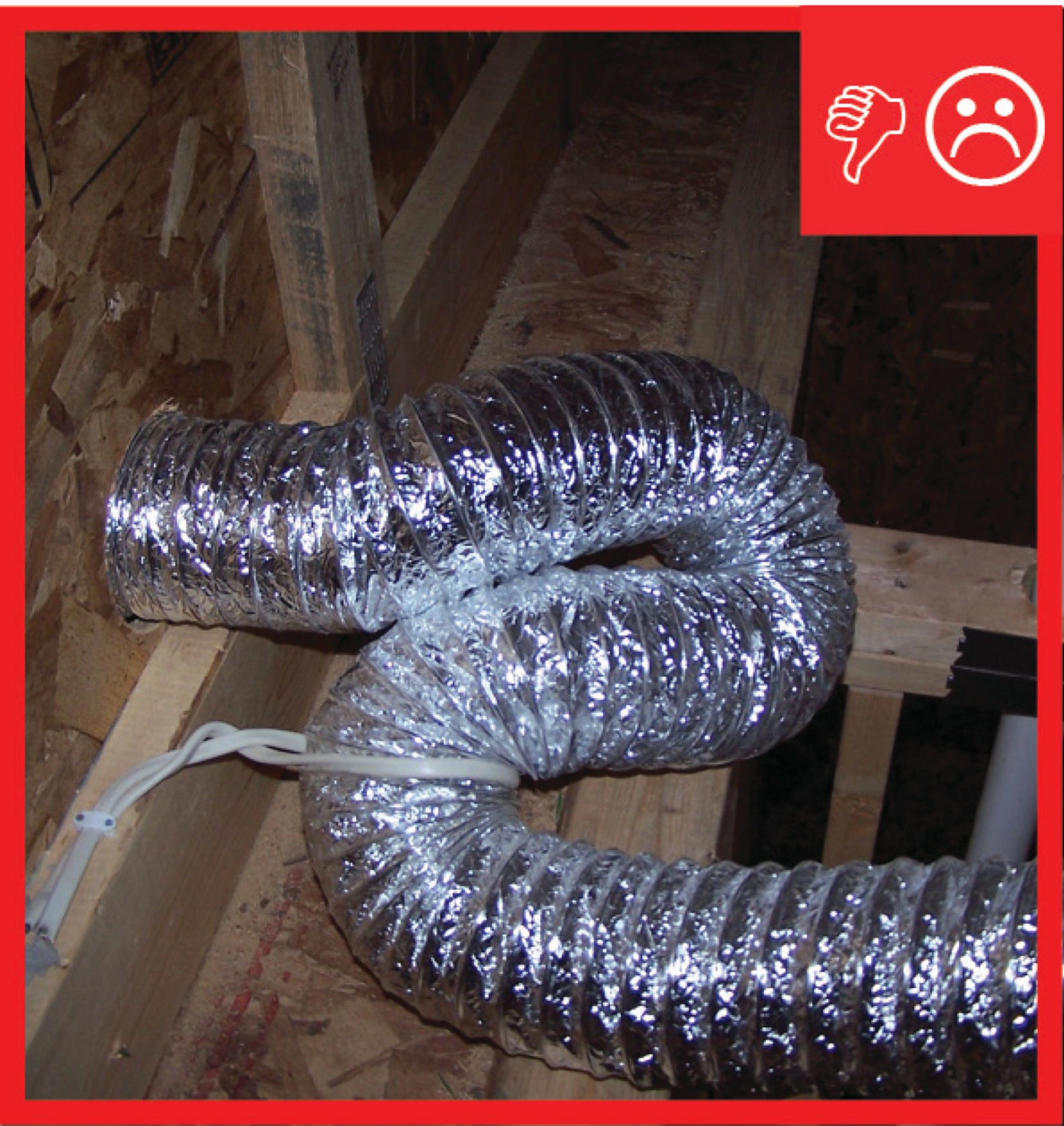
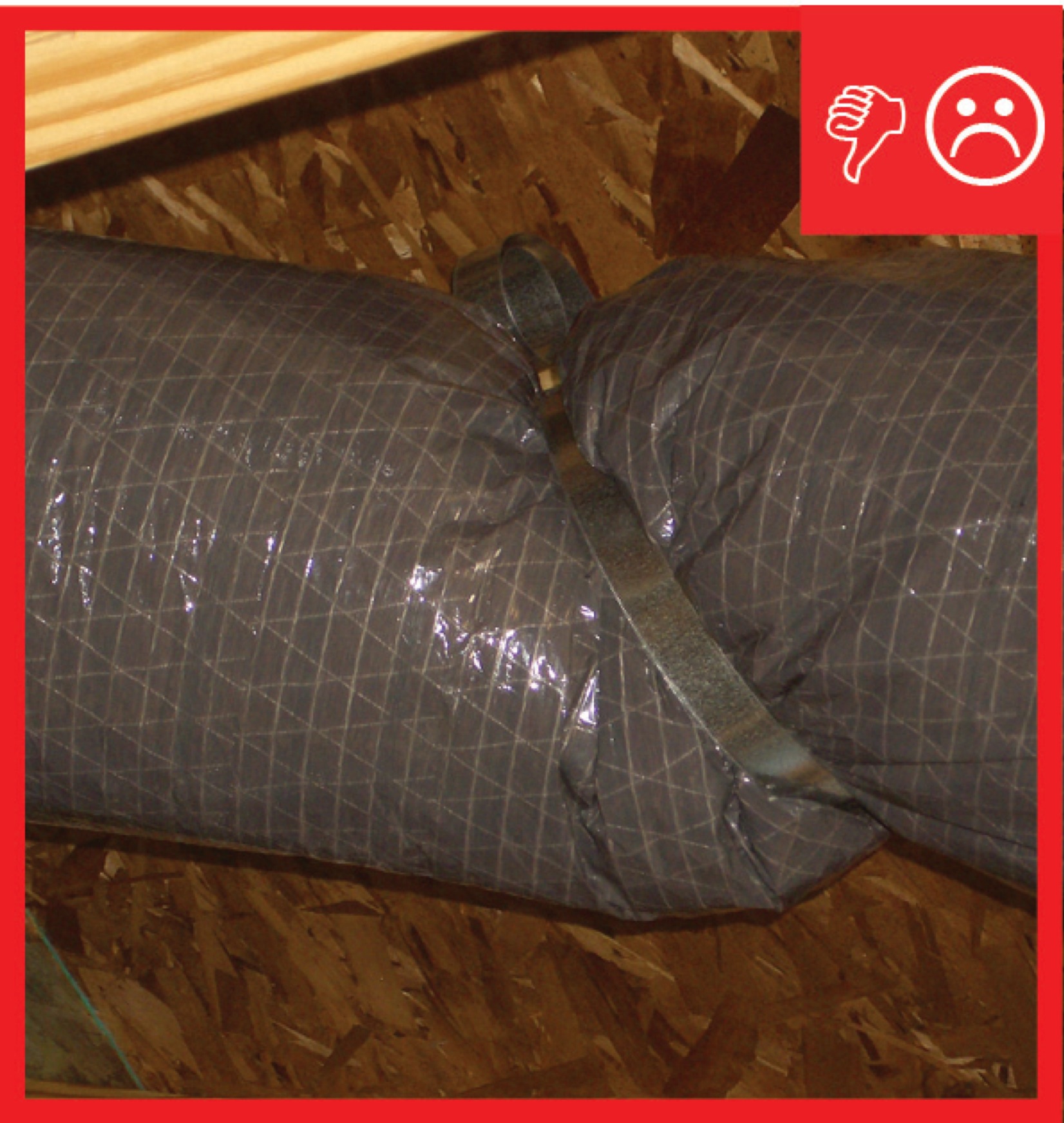
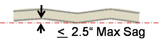
Ducts sagging because supports not installed at regular intervals
Image
Image
Image
Image
Image
Image

Image
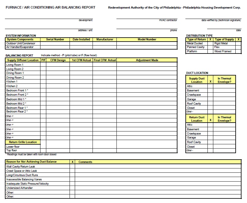
Example of an HVAC installer’s balancing report form
Image
Image
Image
Expanded polystyrene insulation is installed with joints taped and lath attached in preparation for the application of stucco
Image
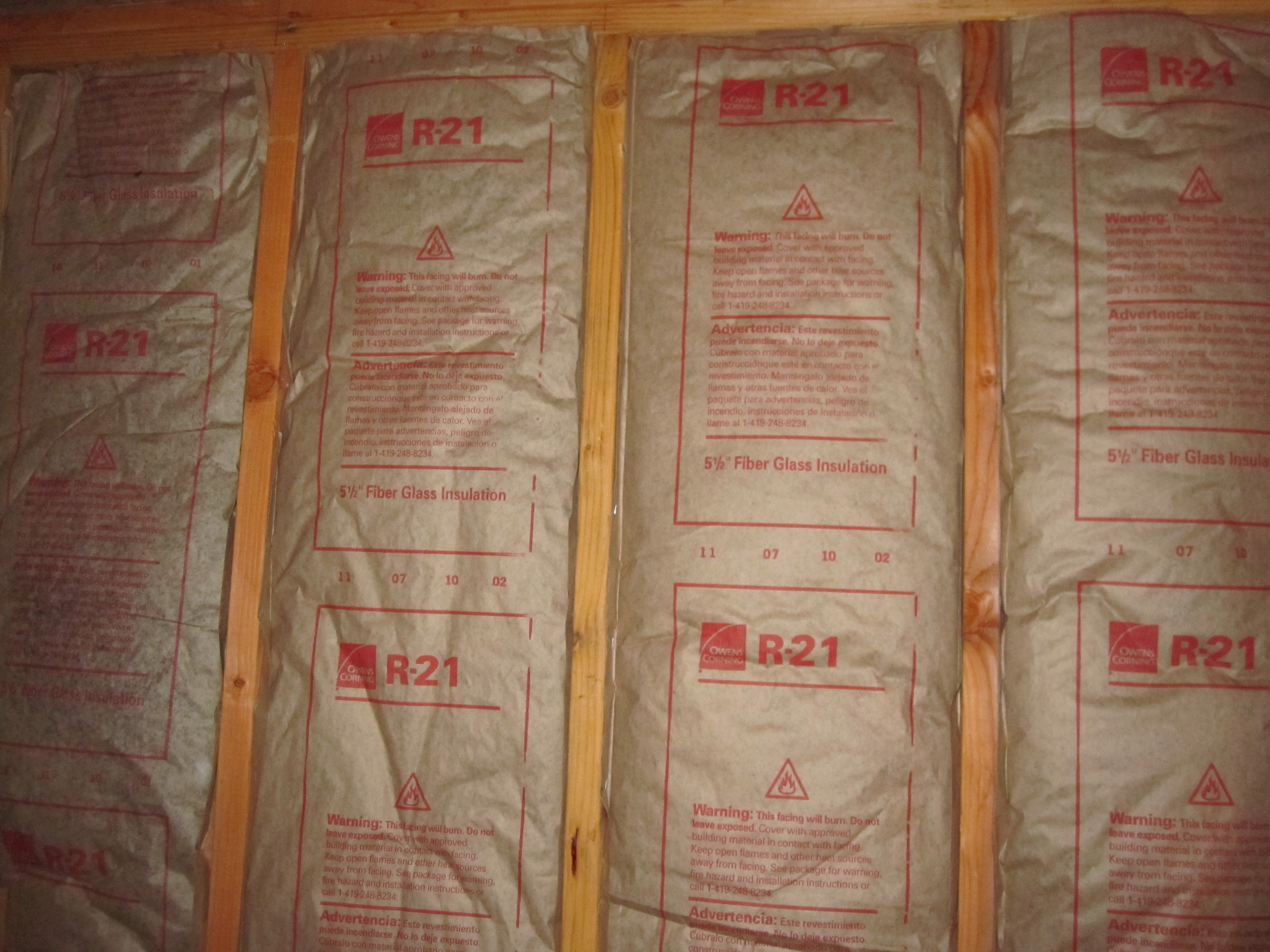
Faced fiberglass batt insulation can be stapled to the stud faces or slightly inset, but avoid compressing the batts
Image
Image
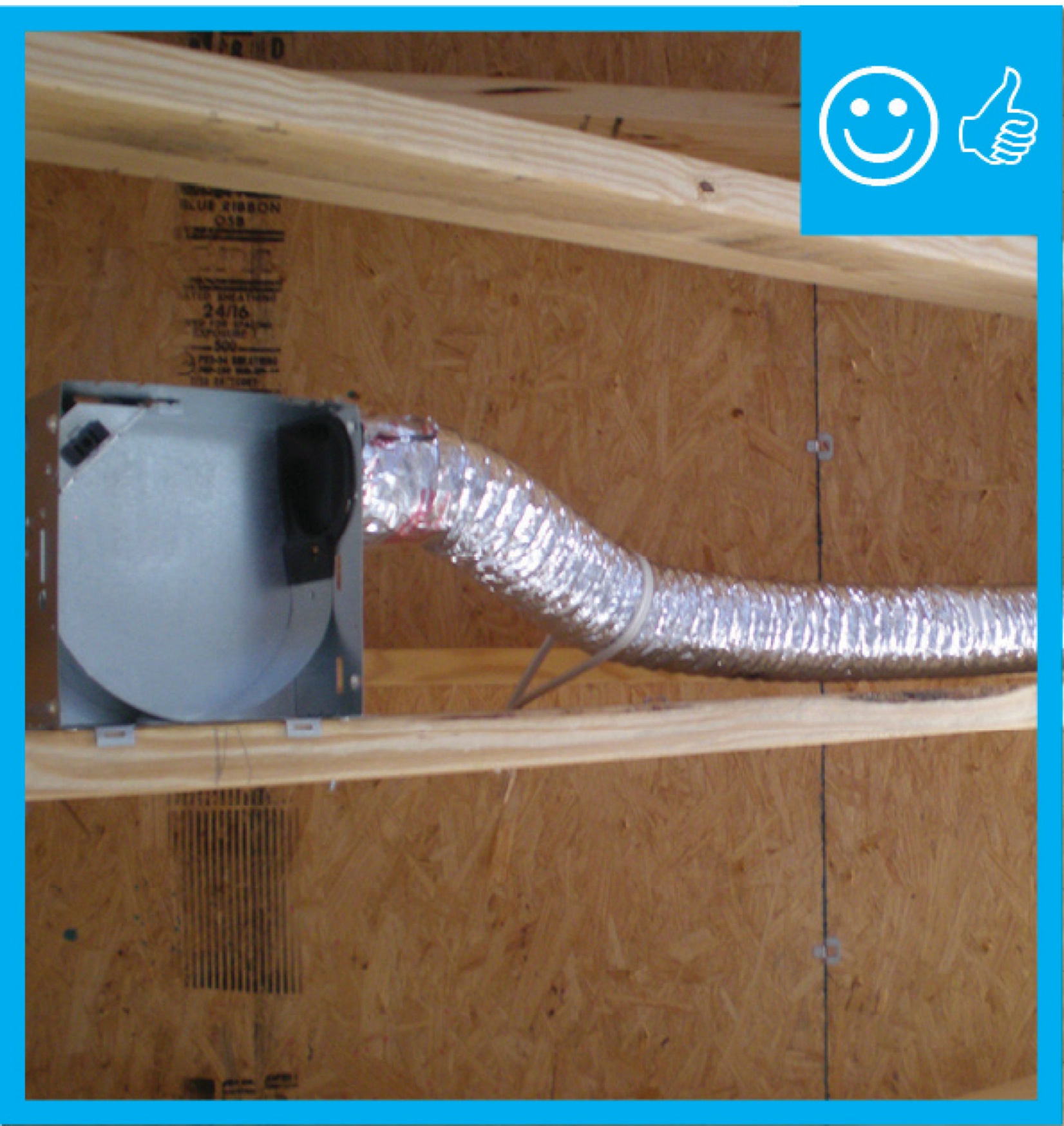
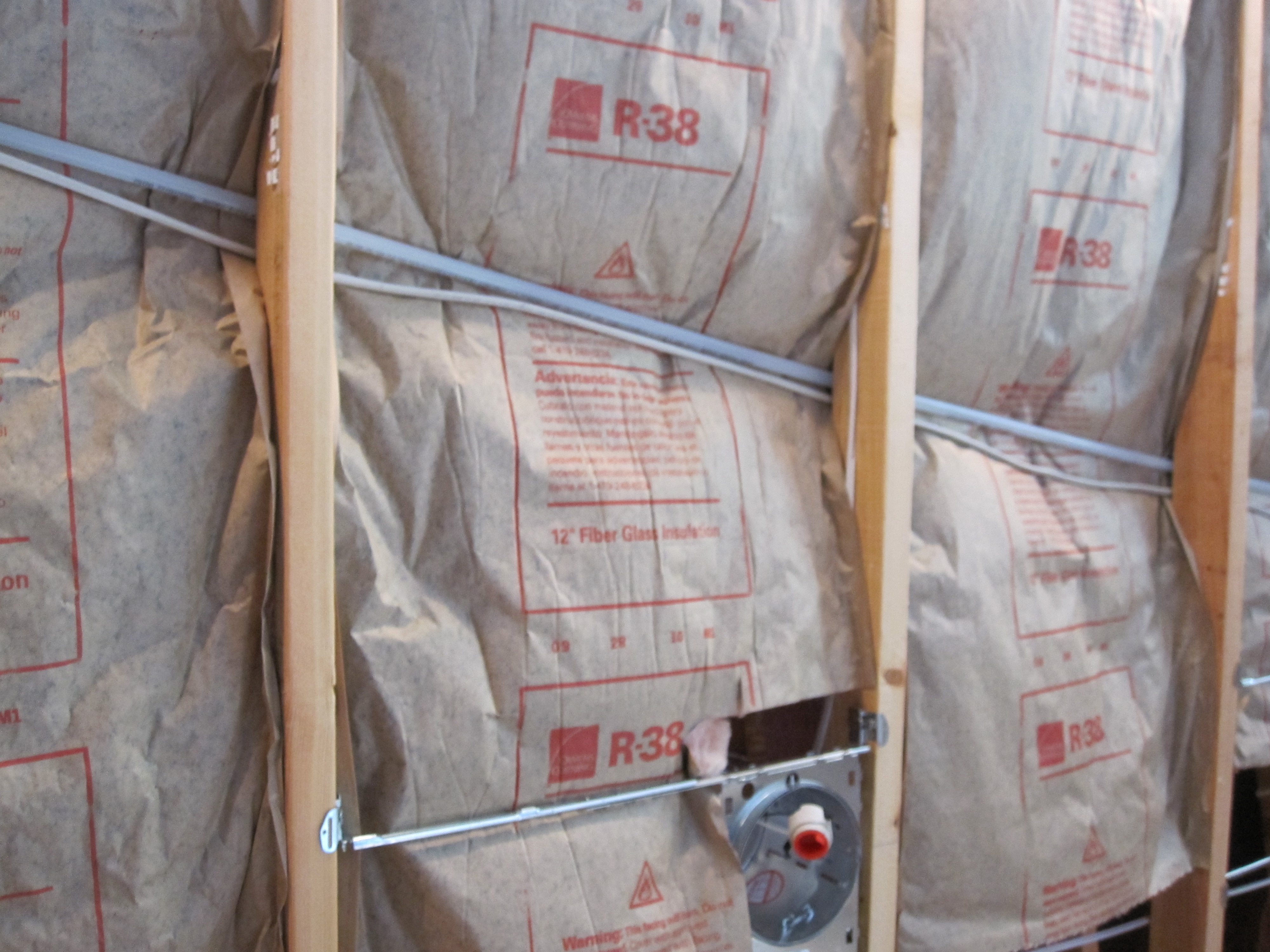
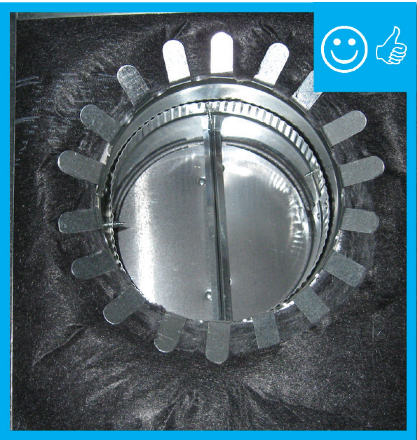
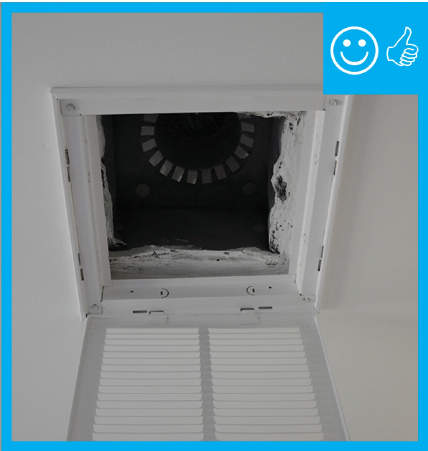
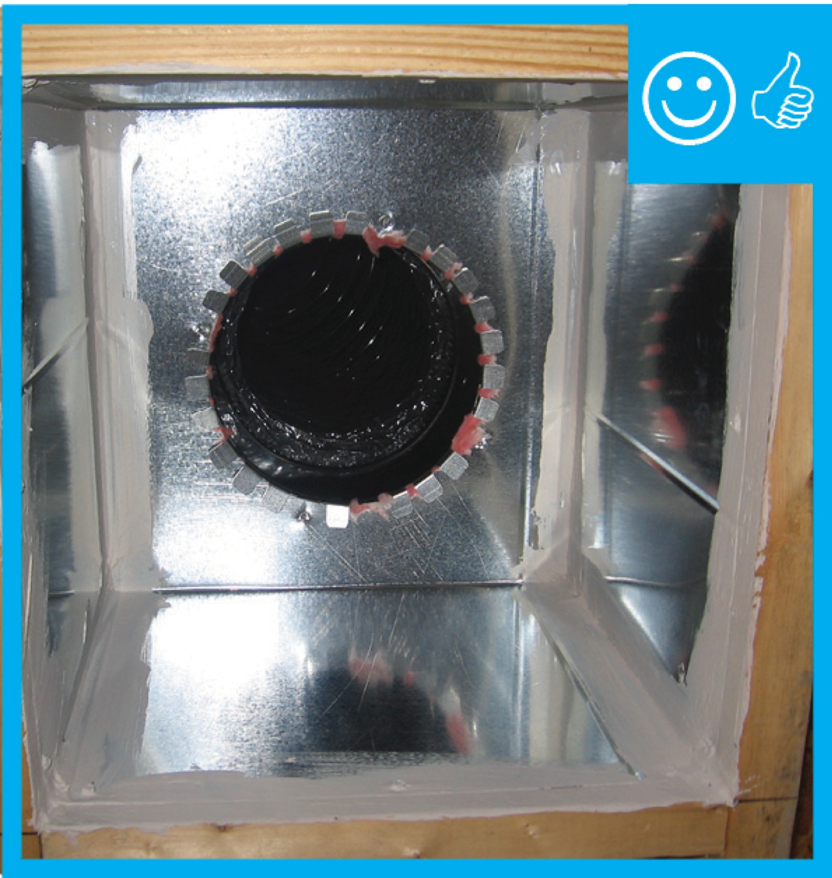
Fan housing was oriented in the correct direction to allow proper exhaust duct installation
Image
Image
Flat roof with cavity spray foam plus loose-fill insulation and gypsum board thermal barrier.
Image
Image
Image
Image
Image
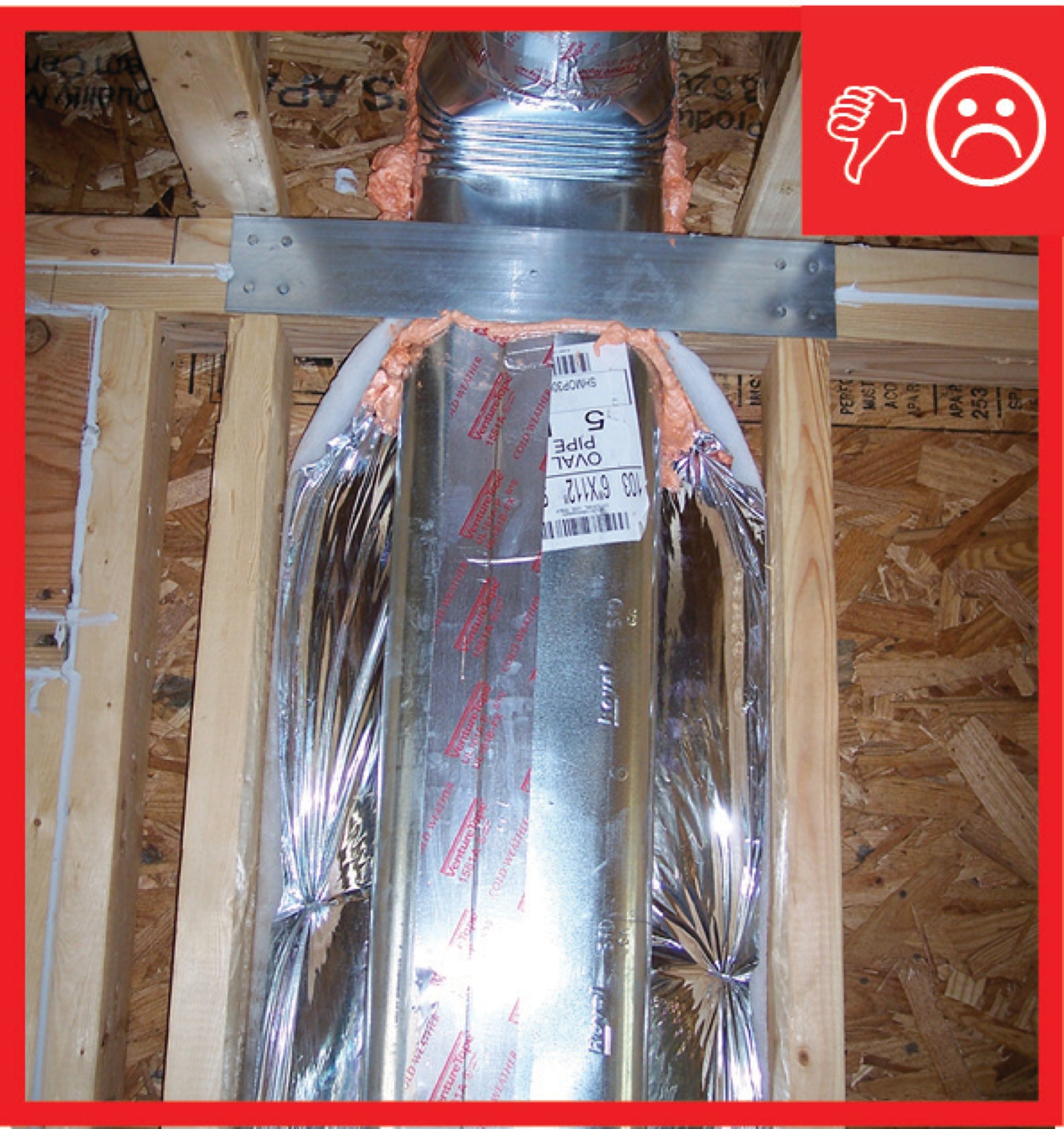
Flexible ducts in unconditioned space not installed in cavities smaller than outer duct diameter; in conditioned space not installed in cavities smaller than inner duct diameter
Image
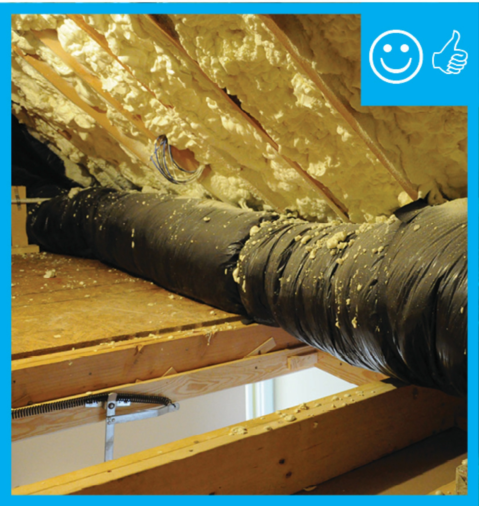
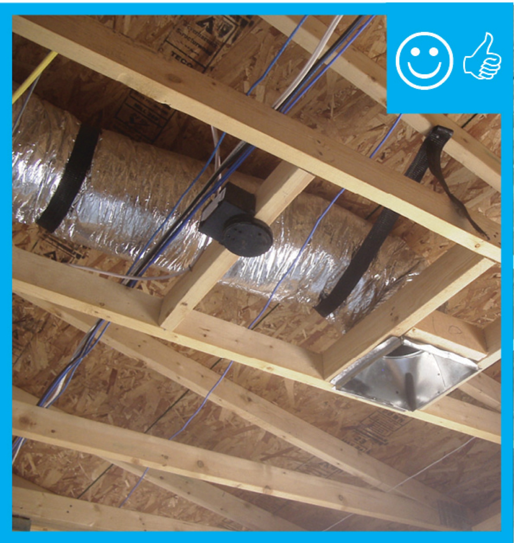
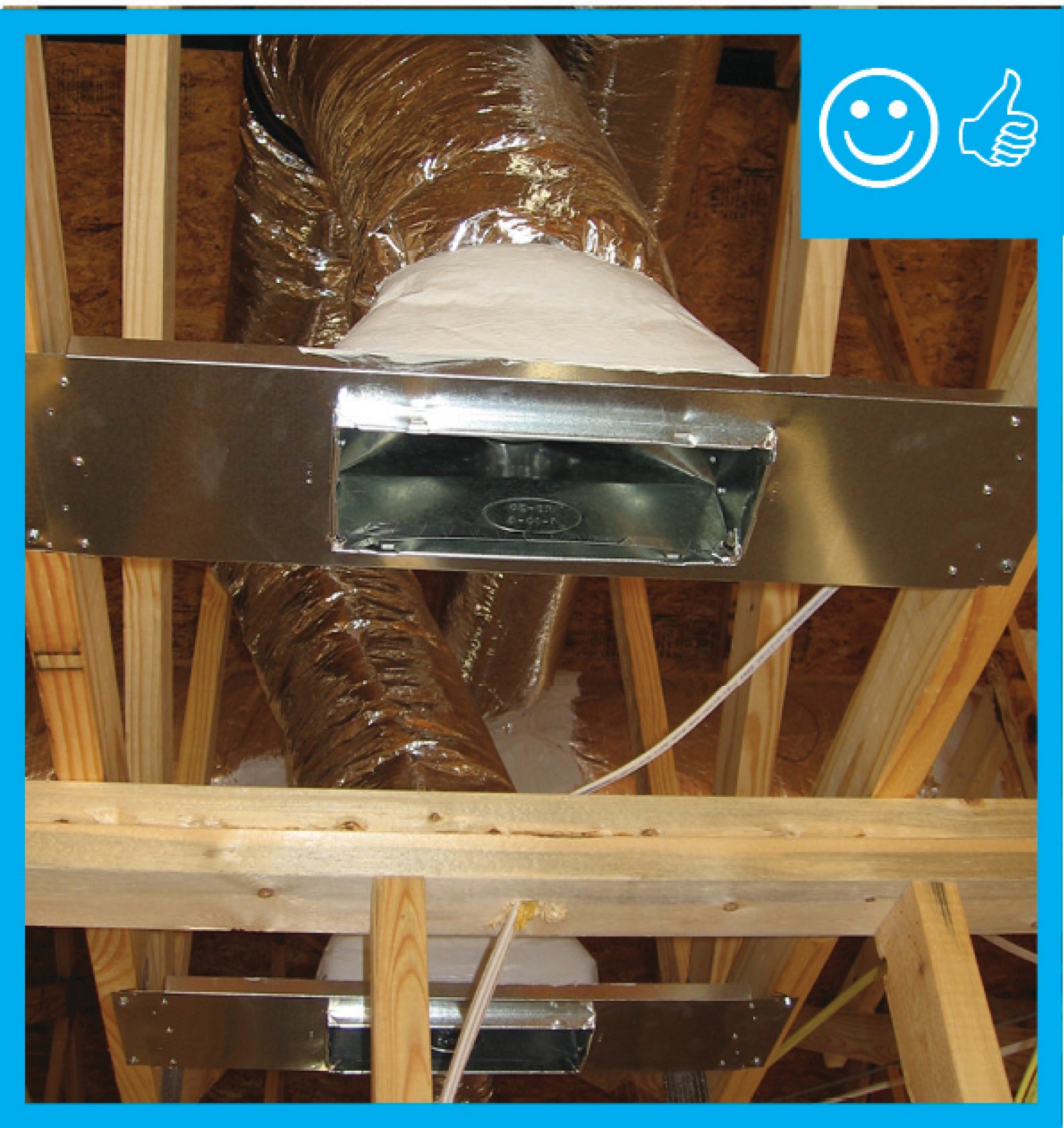
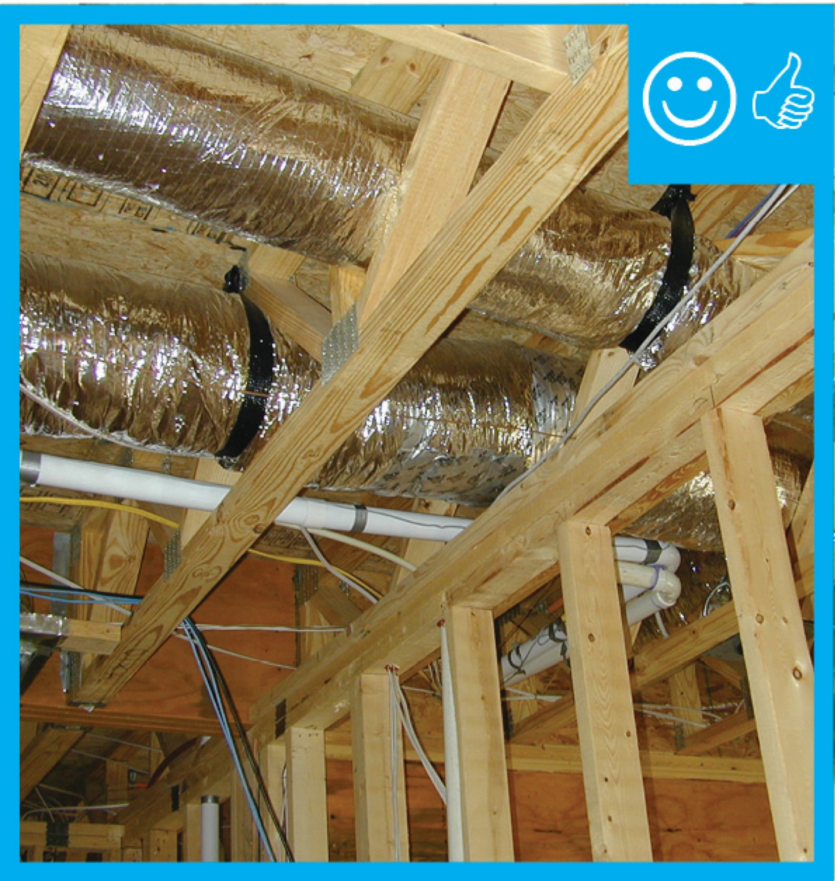
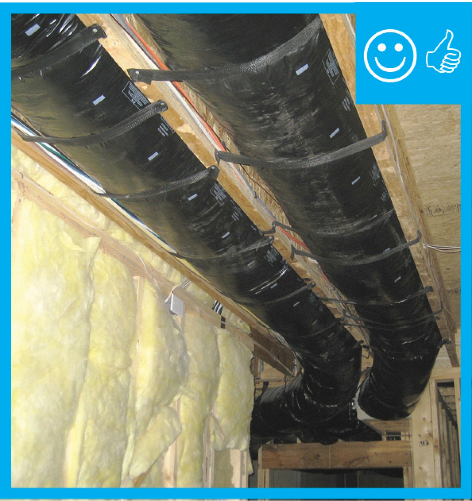
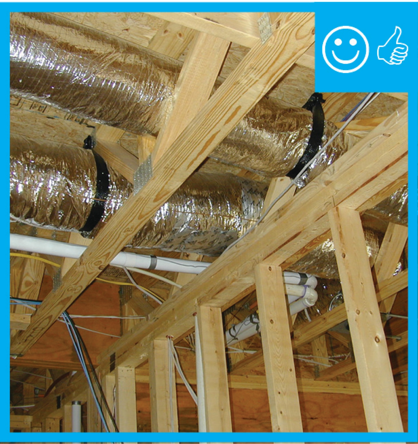
Flexible ducts supported at intervals as recommended by mfr. but at a distance ≤ 5 ft
Image
Image
Image
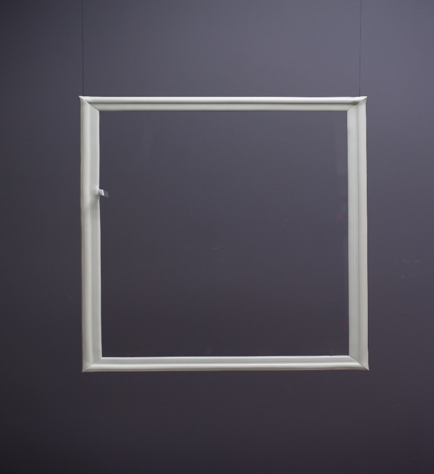
For factory-made interior removable storm windows, follow the manufacturer’s instructions for measuring the window frame
Image
Image
Furnace filters come in many sizes; verify the correct size when purchasing for proper fit in the filter slot.
Image
Image
Image
Image
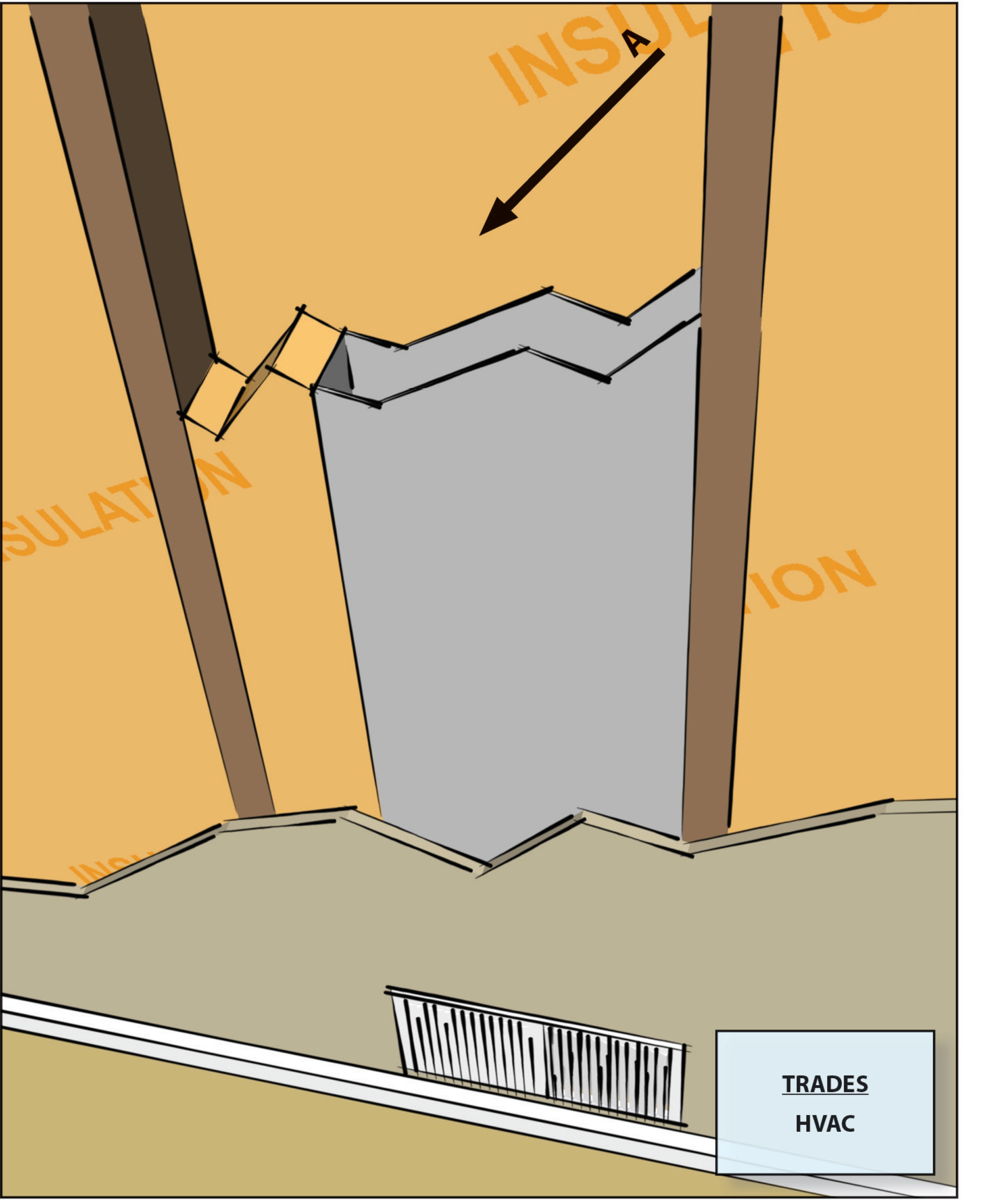
HVAC ducts, cavities used as ducts, and combustion inlets and outlets may pass perpendicularly through exterior walls but shall not be run within exterior walls unless at least R-6 continuous insulation is provided on exterior side of the cavity
Image
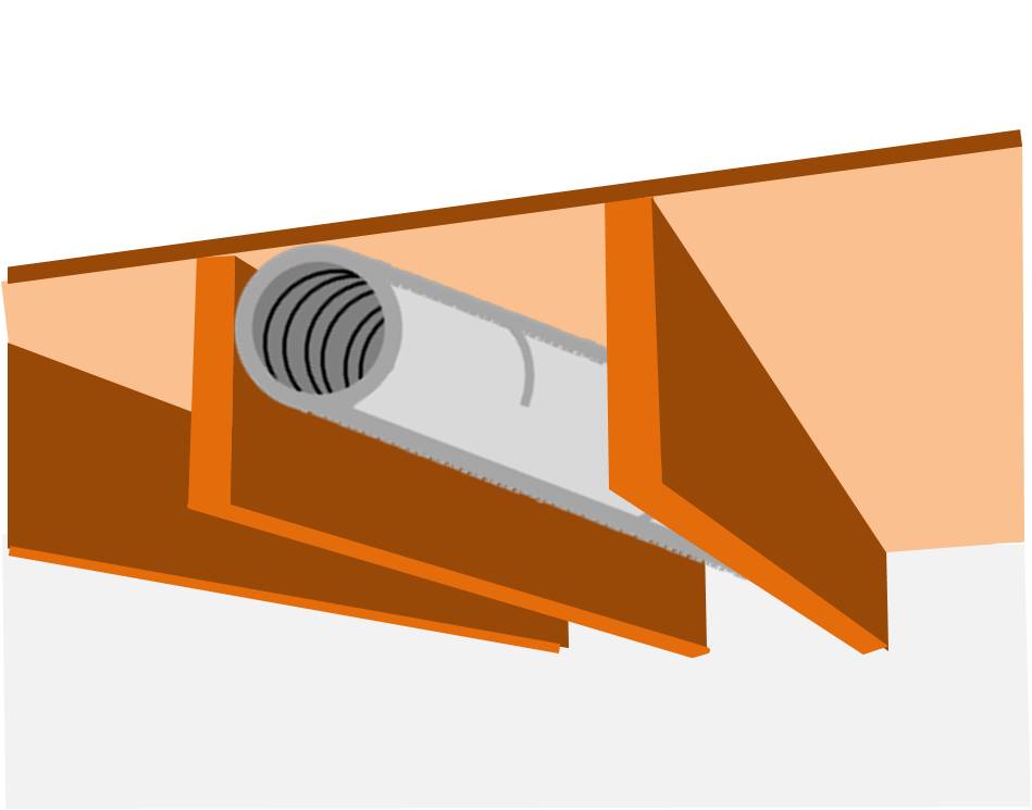
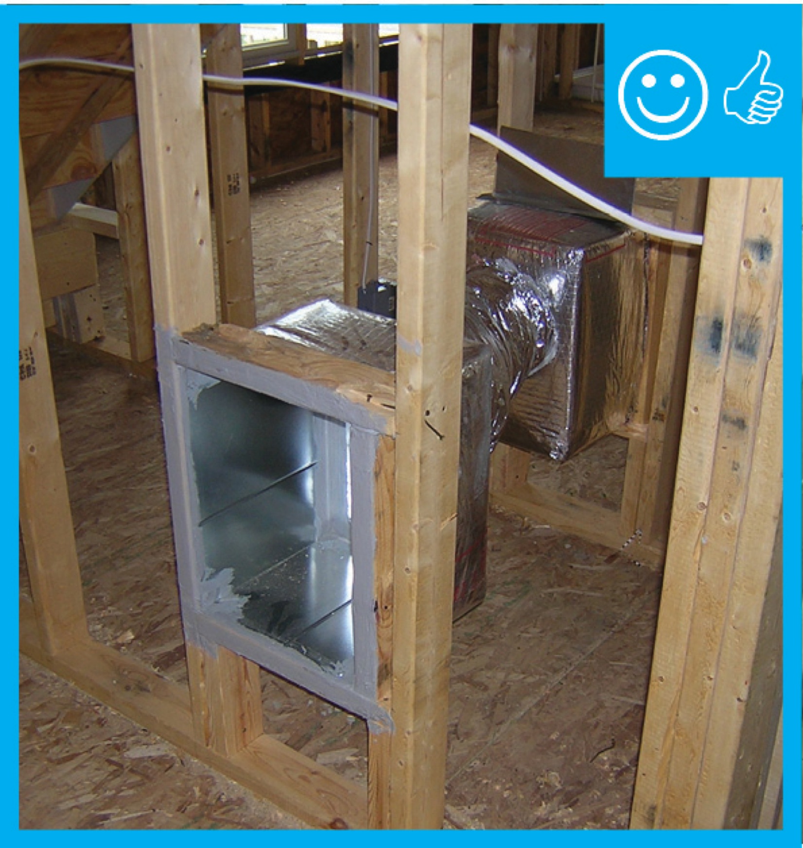
If a dropped soffit is used to house a duct, the soffit space must equal the duct diameter plus the insulation thickness
Image

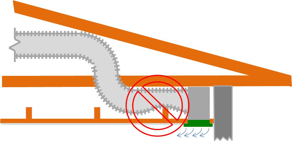
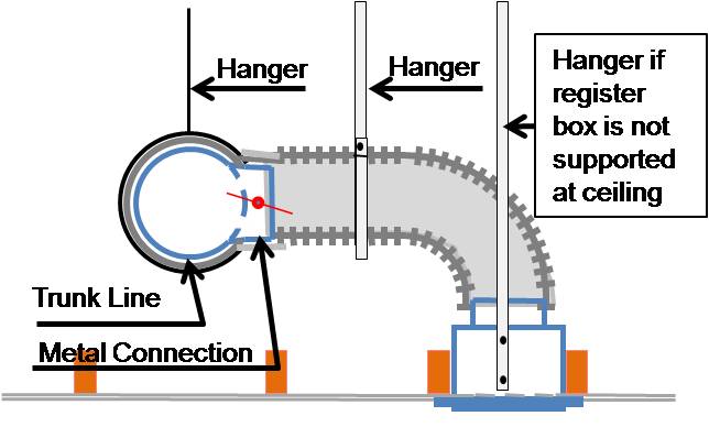
If airflow must be limited to a supply register, use balancing dampers at the trunk line rather than looping duct to control airflow
Image
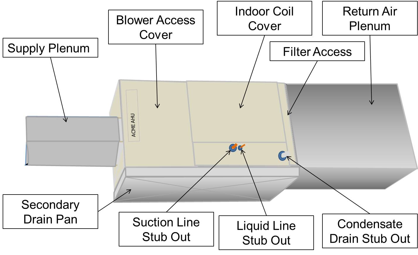
If filter is inaccessible, locate the air filter between the return air plenum and the air handler box
Image

If furnace is accessible, locate the air filter between the return air plenum and the air handler box
Image
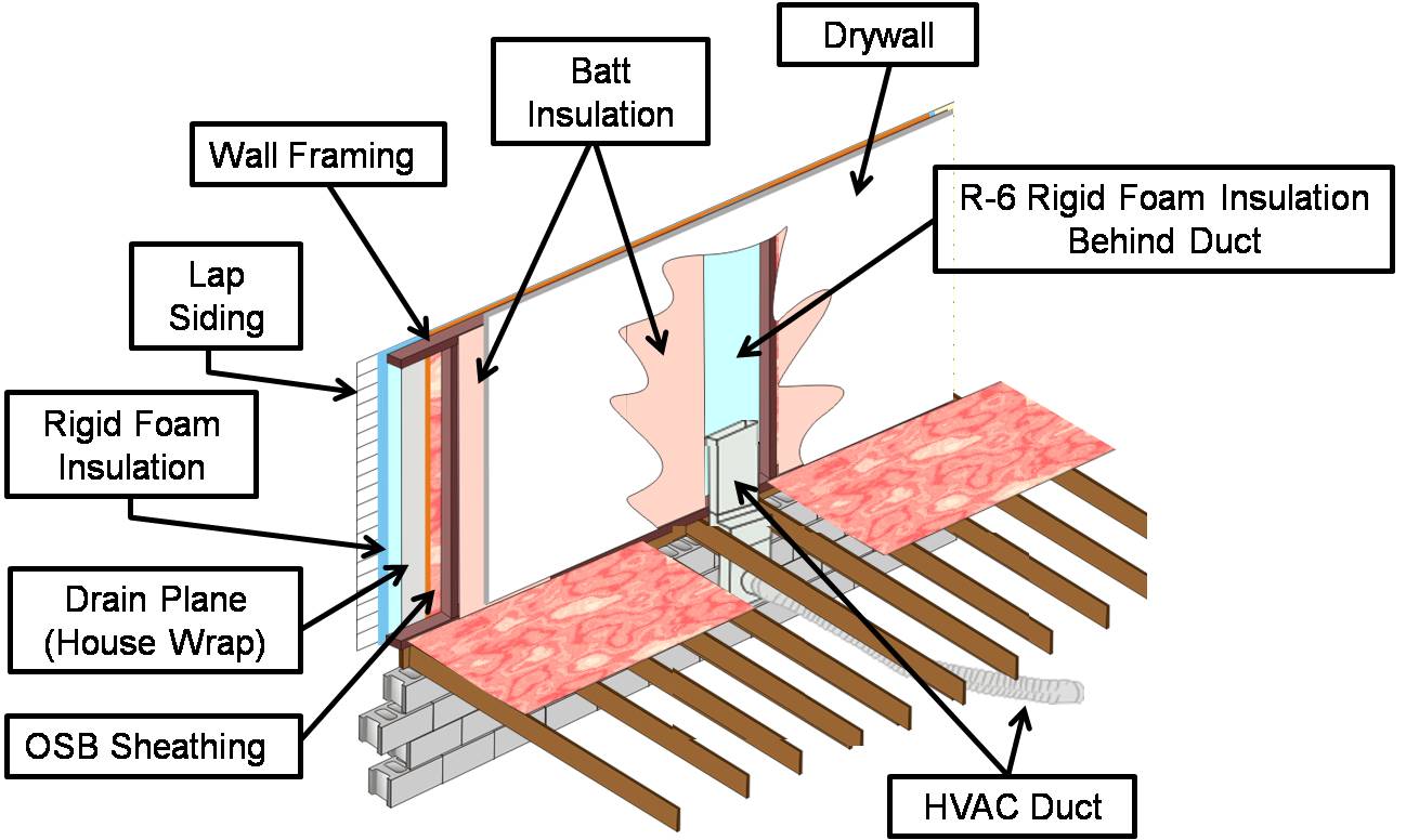
If HVAC duct must be installed in an exterior wall, separate it from the exterior with at least R-6 of continuous rigid insulation
Image

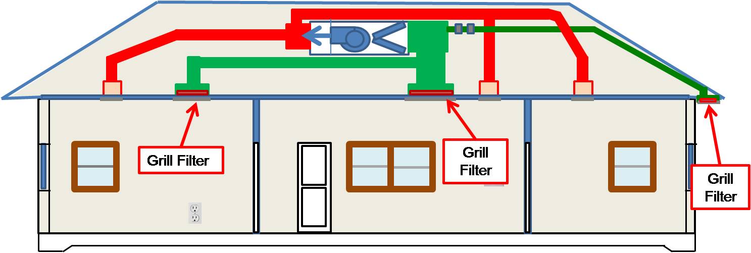
If the furnace is hard to access, locate filters at return registers covered by hinged grilles that are easy to open from inside the home
Image
Image
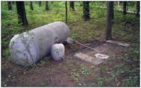
Improperly installed fuel tanks can break free from attachments under the force of flood waters, risking broken fuel lines which could cause fire or explosion. Here, the tank is tethered only by the gas piping, which is not designed to perform this functi
Image
Inadequate amount of insulation installed with compression, misalignment, and voids
Image
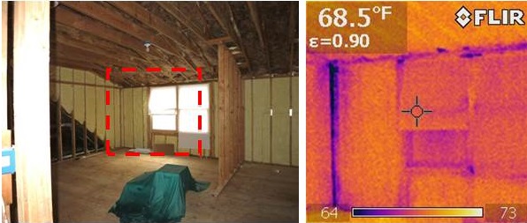
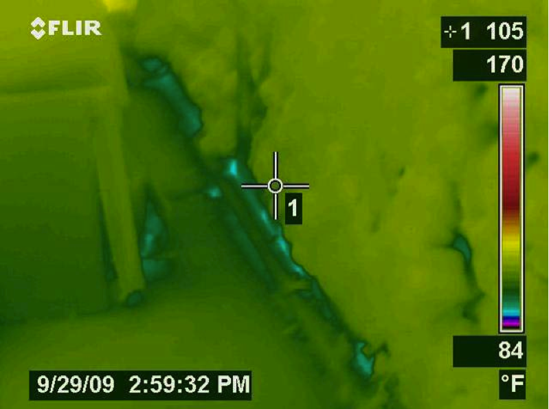
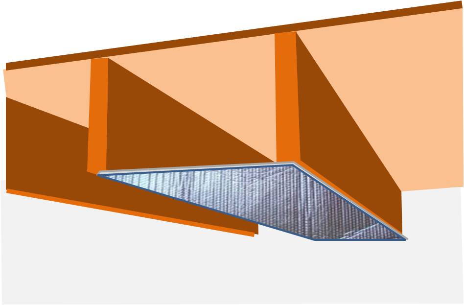
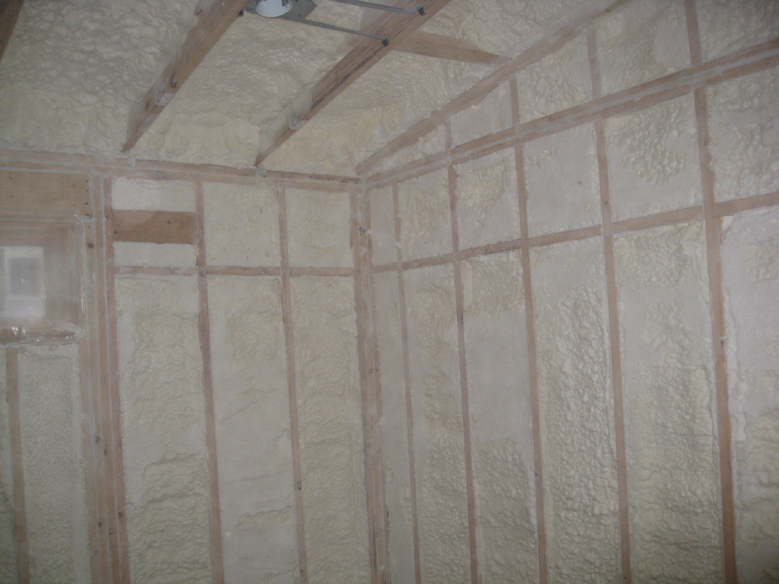
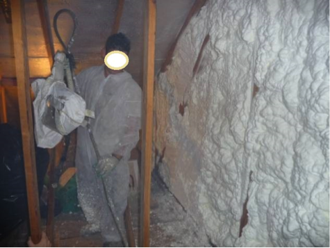
Infrared thermography during depressurization testing reveals air leakage at corner of spray foam-insulated room where wood-to-wood seams in framing were not air sealed
Image
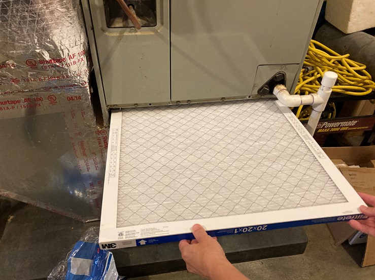
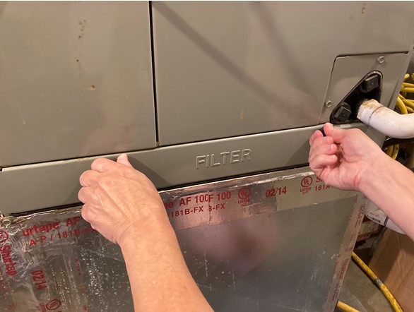
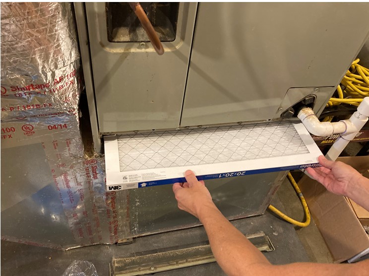
Insert the new furnace/air handler filter in the filter slot of the furnace or air handler with the arrow pointed in the direction of air flow.
Image
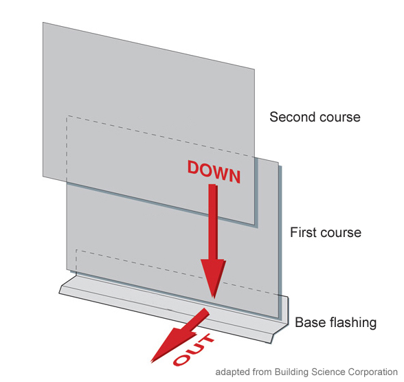
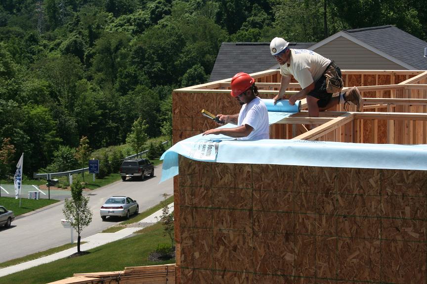
Install all layers of the drainage plane to overlap, not underlap, to direct bulk water down and out of the wall.
Image
Image

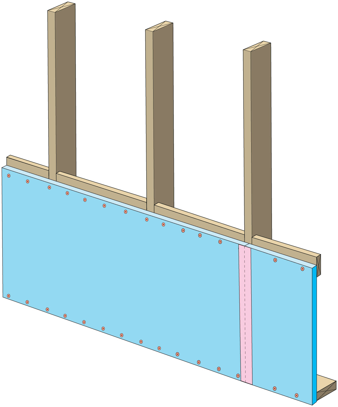
Install bottom layer of rigid insulation
Image
Image
Image
Image
Install supply registers in floors or ceilings to avoid routing ducts through exterior walls
Image
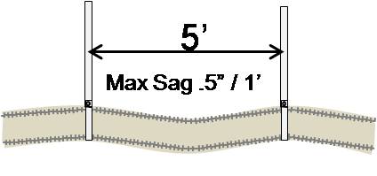
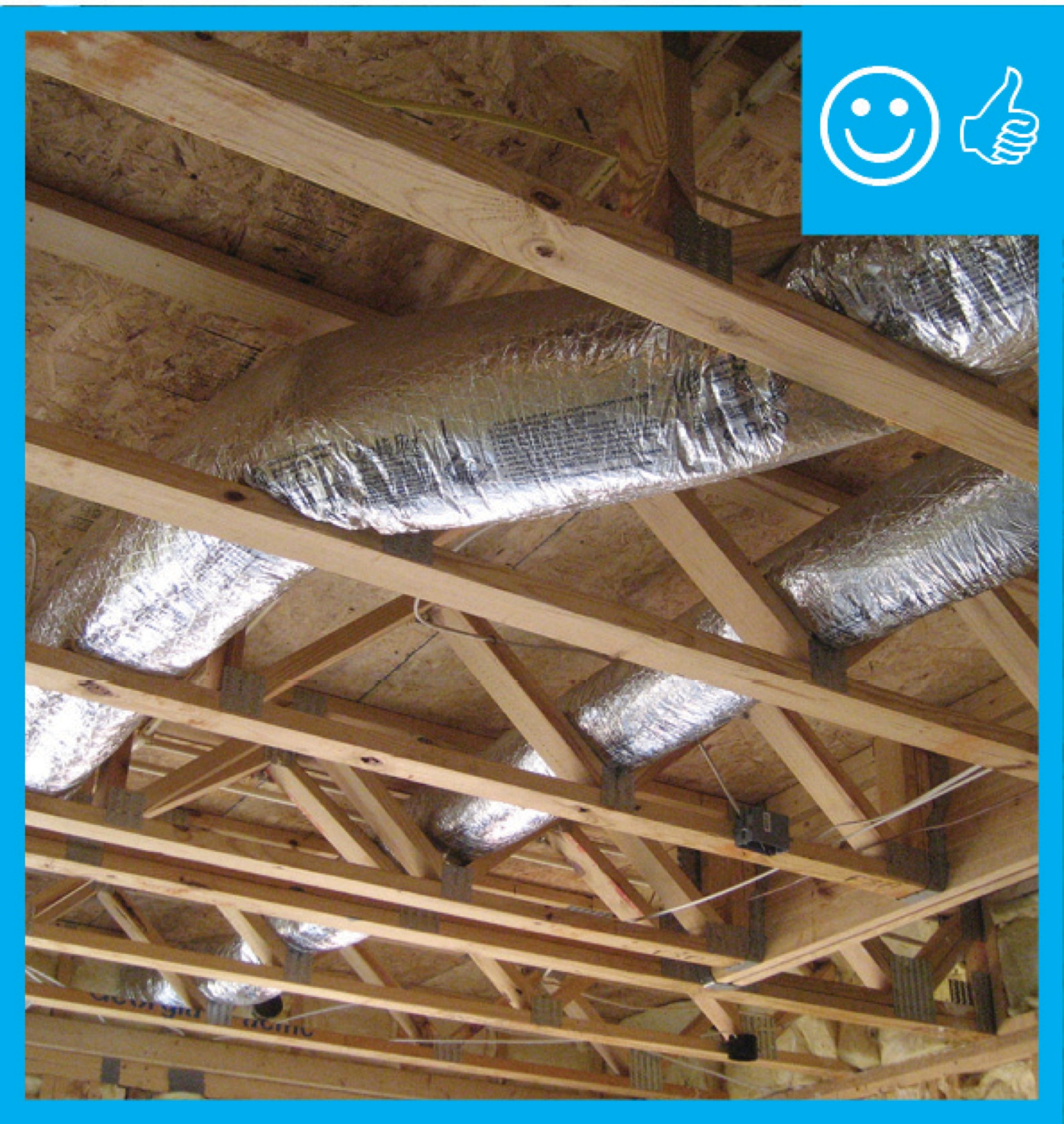
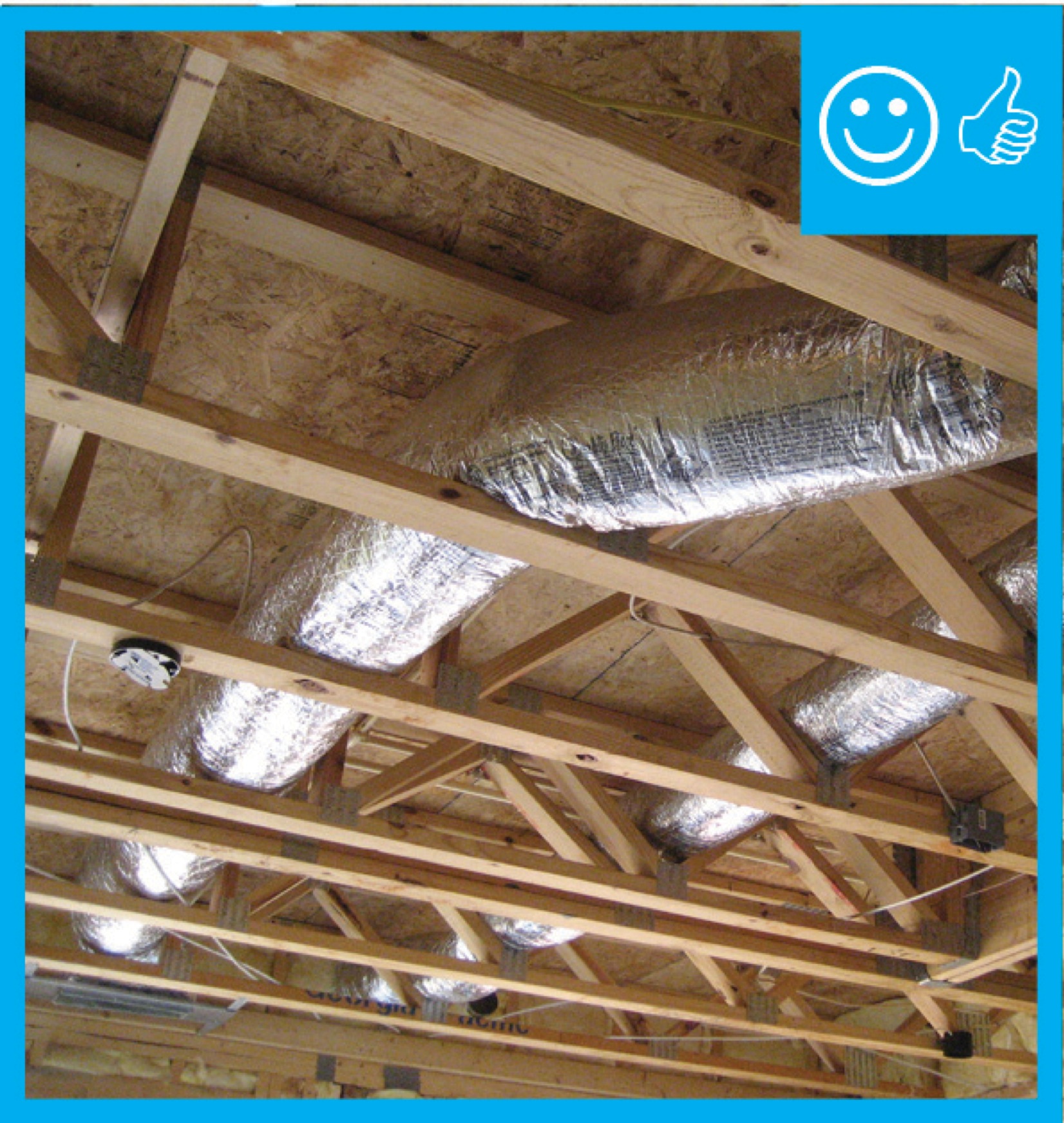
Install supports every 5 feet so that maximum allowable sag in flexible duct is no more than one-half inch per foot
Image
Install supports every 5 feet so that maximum allowable sag in flexible duct is no more than one-half inch per foot
Image
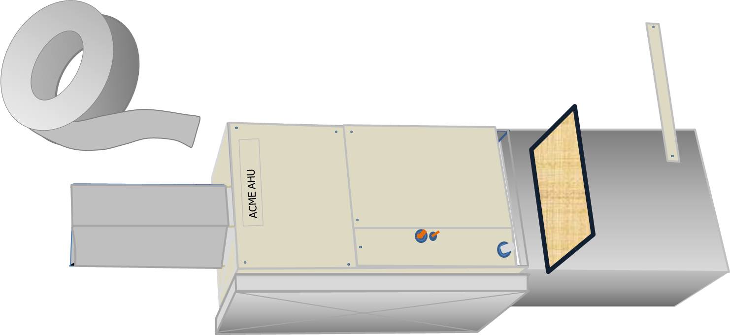
Install the filter media box between the return air plenum and the air handler box
Image
Image
Image

Image
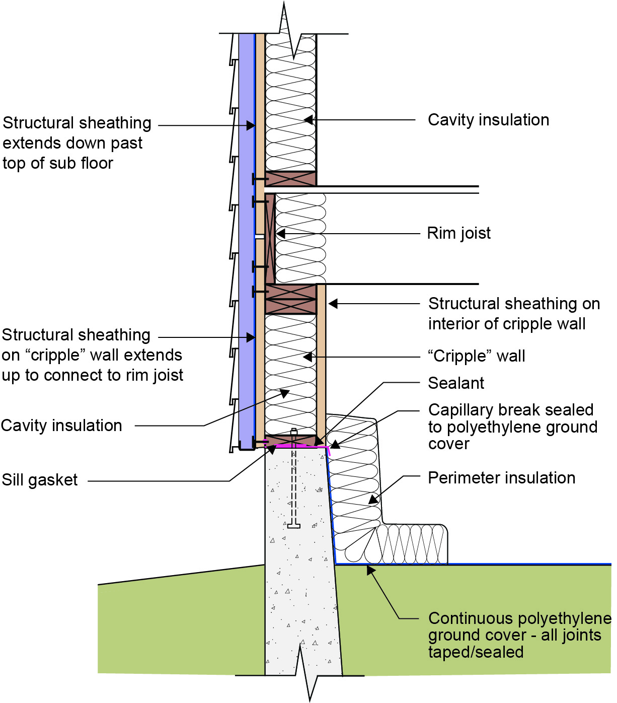
Insulating a crawlspace foundation with “cripple wall” in warm climates; in Climate Zones 5+ replace the foil- or plastic-faced fiberglass batt/roll insulation with impermeable rigid insulation or closed-cell spray polyurethane foam
Image
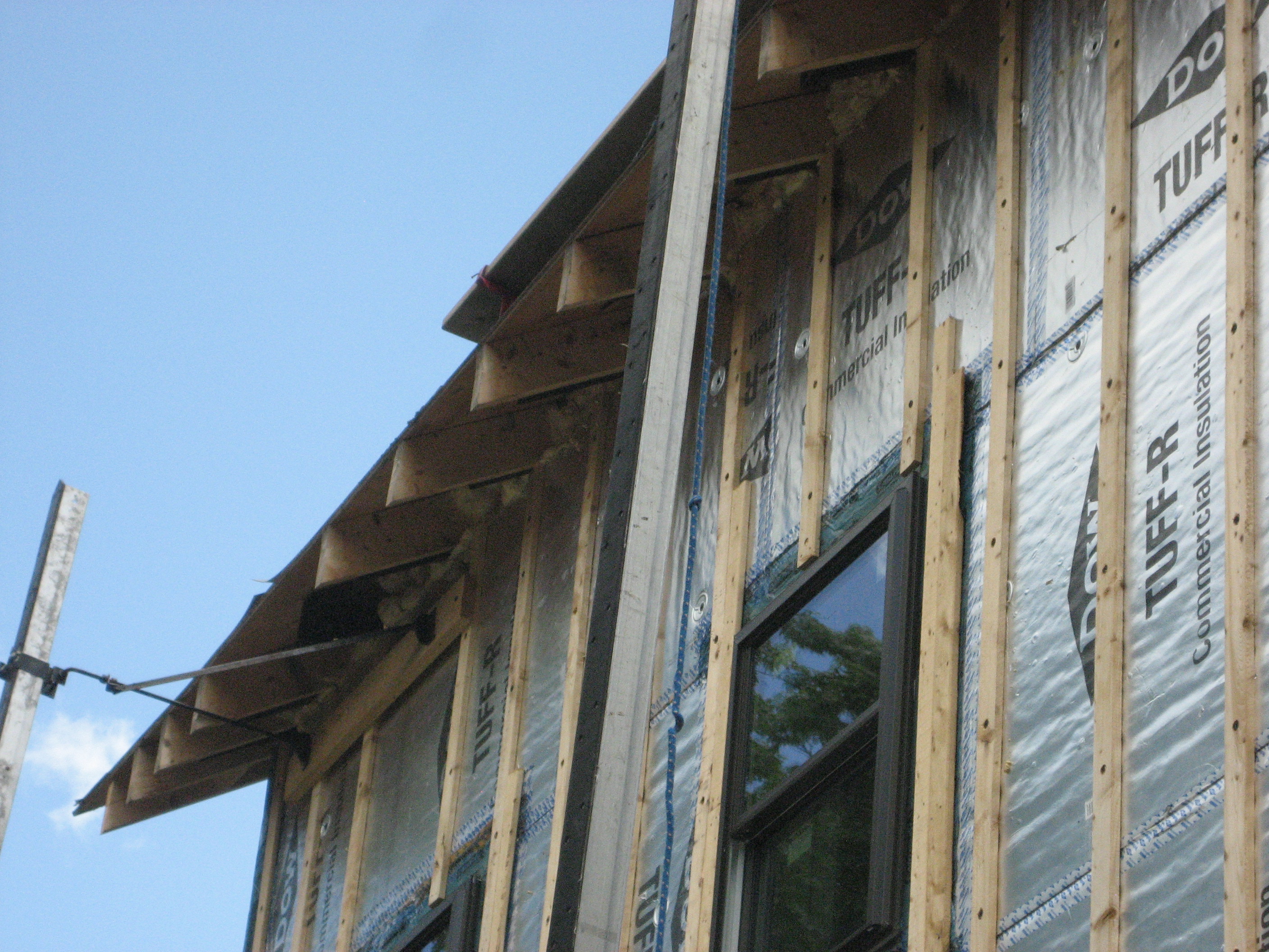
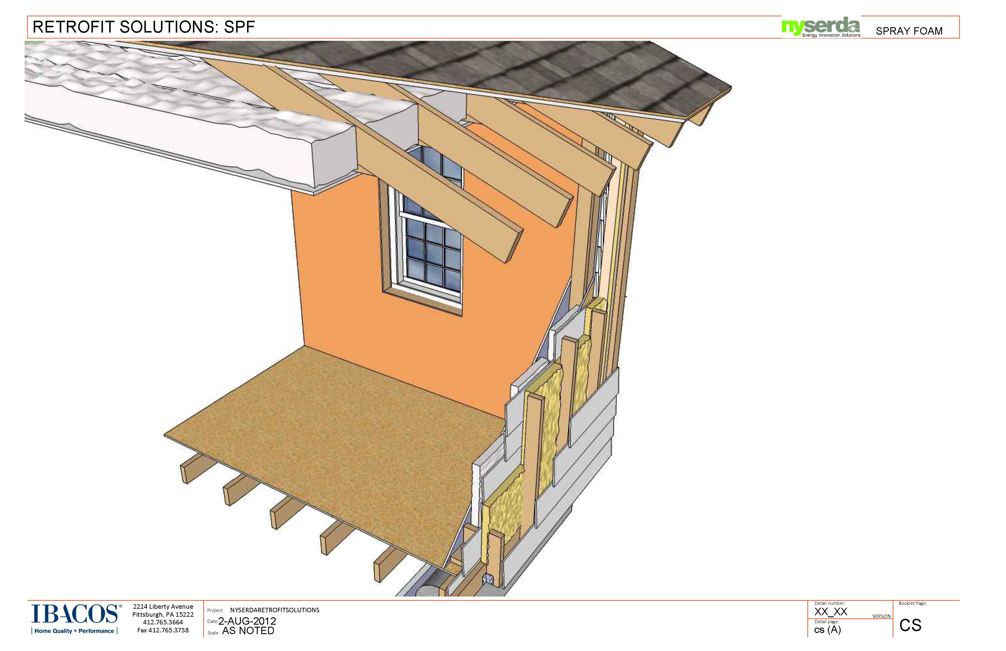
Insulating sheathing is extended up to the roof rafters and sealed around the framing with spray foam as part of this exterior wall retrofit
Image
Insulation was added to the walls and ceiling of this existing home from the inside as part of an extensive retrofit to avoid replacing original 1-inch shiplapped sheathing.
Image
Image
Image

Lay out duct so that no radius of a bend or turn is less than the diameter of the airway
Image
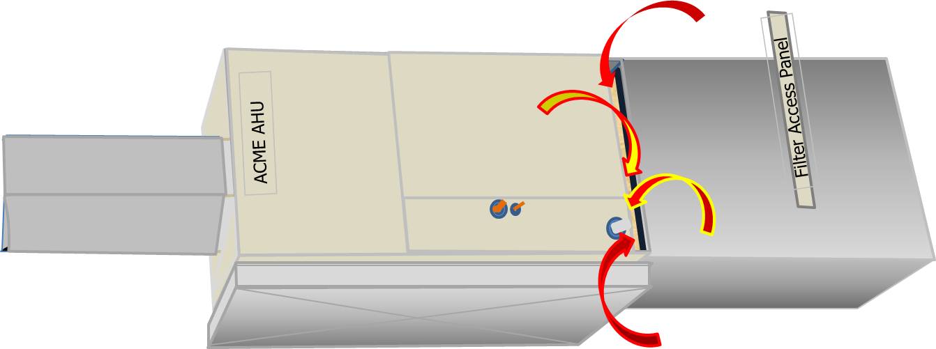
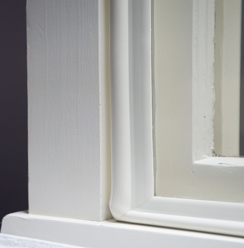
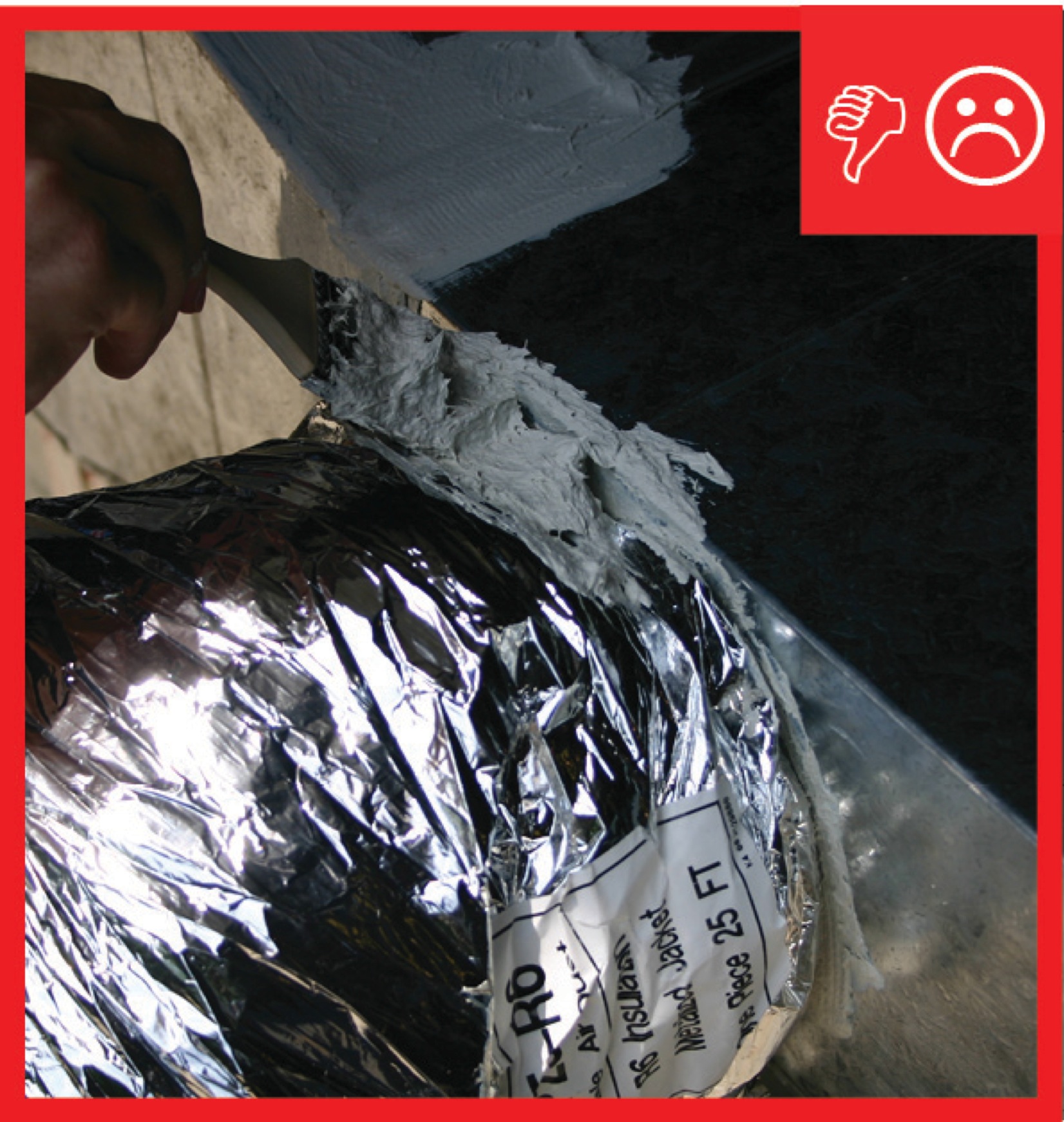
Leaks at the air filter cover panel can draw in unconditioned or undesirable air
Image
Ledger board, metal brackets, and vertical 2x4s have been installed in preparation for exterior spray foam in this retrofit exterior wall insulation technique
Image

Limited attic access can make inspections for missing air barriers and insulation challenging
Image
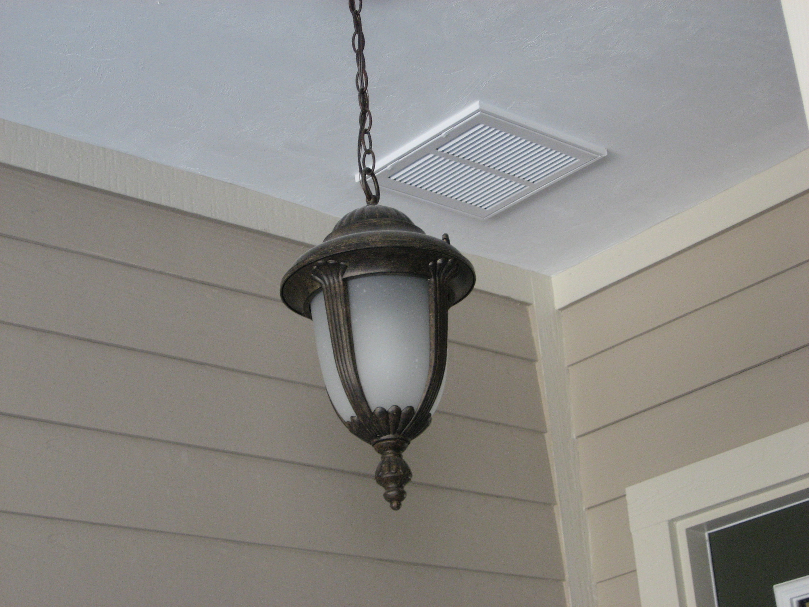
Locate the fresh air intake away from pollution sources and in an easily accessible location
Image
Image
Image
Image
Image
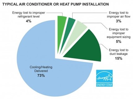
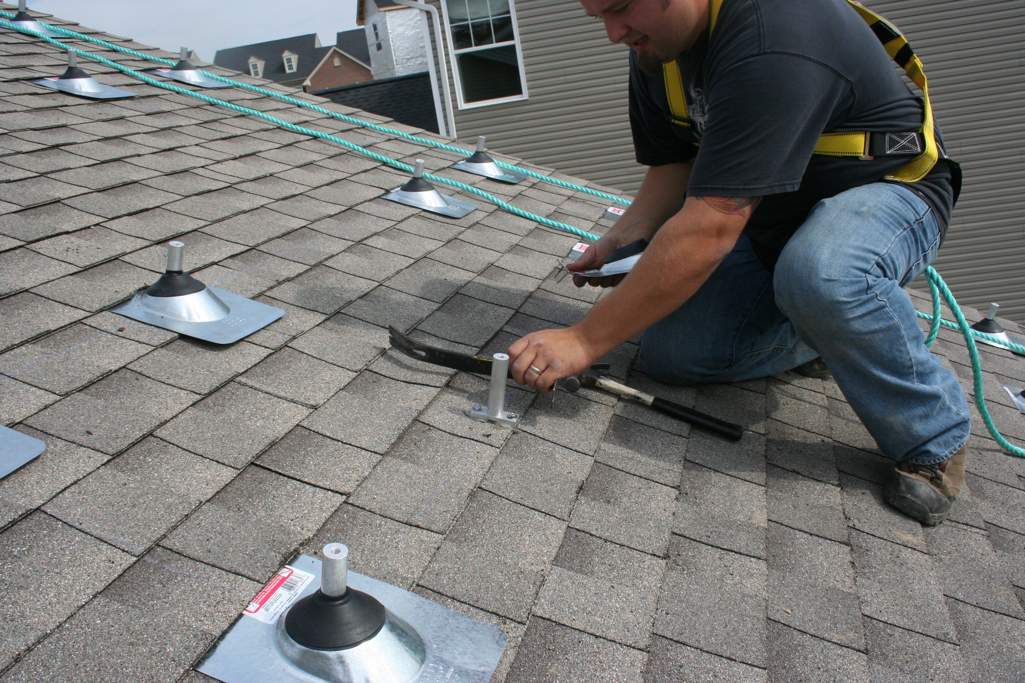
Most residential heat pumps are installed incorrectly and with energy-wasting faults.
Image
Image
Image
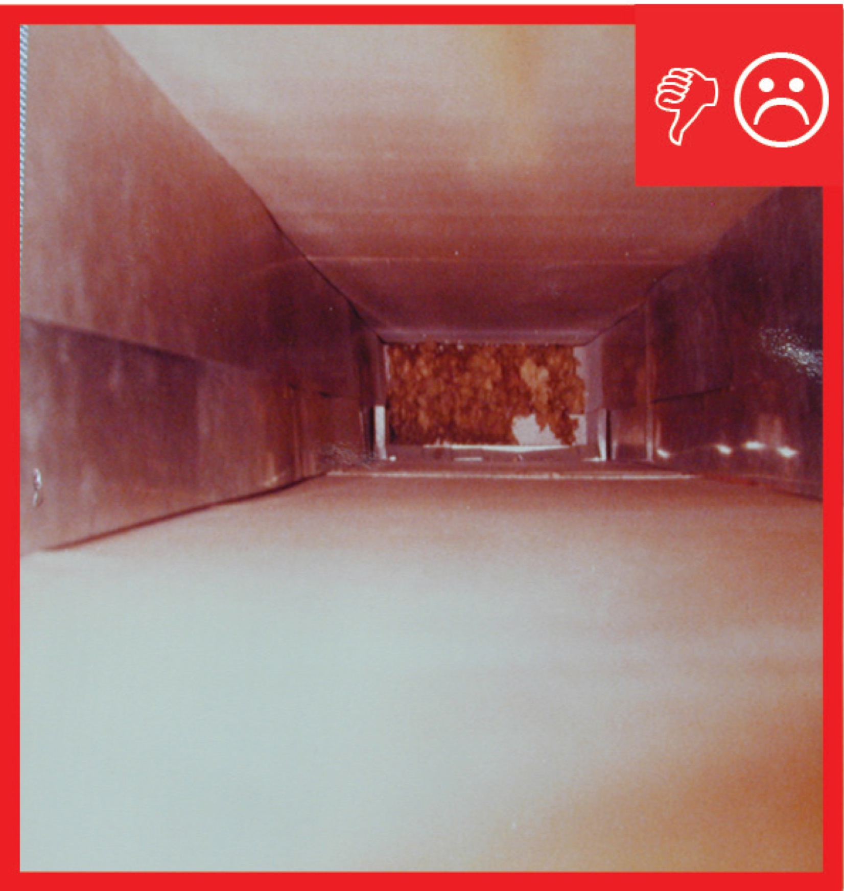
Open floor trusses used as return air plenums can draw air from any place connected to that floor
Image
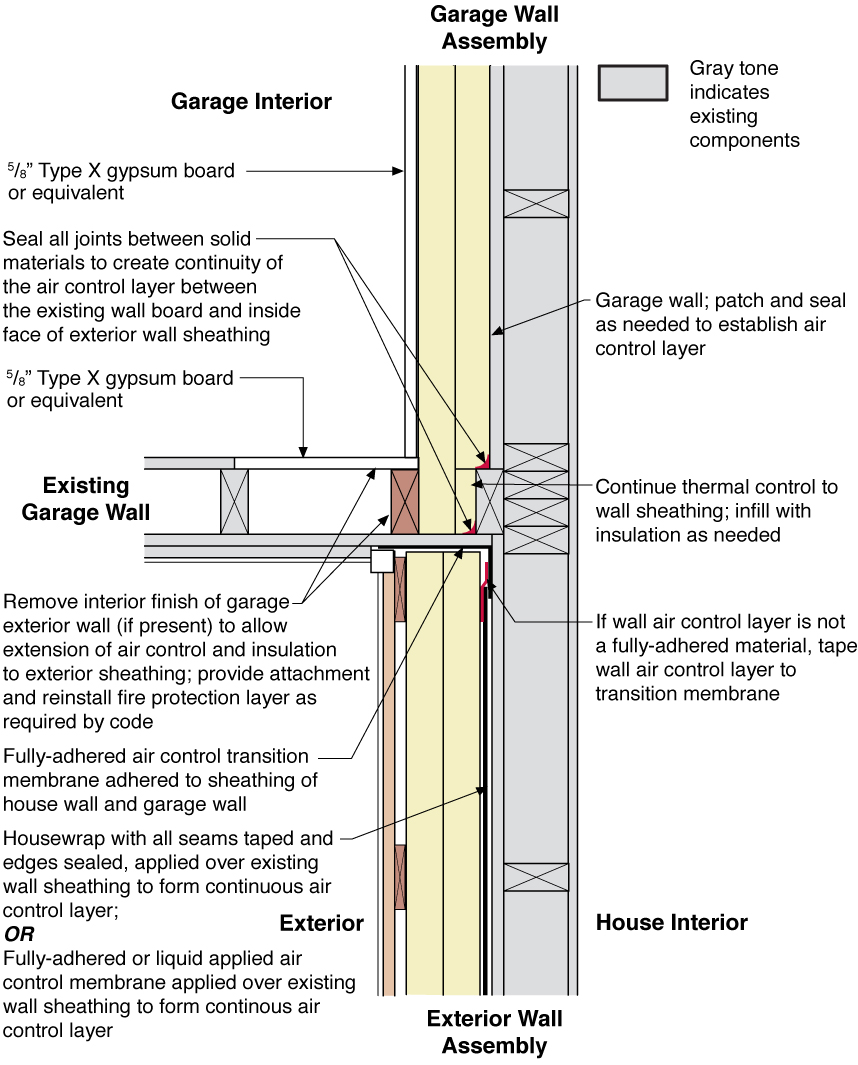
Plan view (from above) showing how the existing garage wall gypsum board is cut away to air-seal the shared wall before adding rigid foam insulation on the garage and exterior walls of the home.
Image
Image
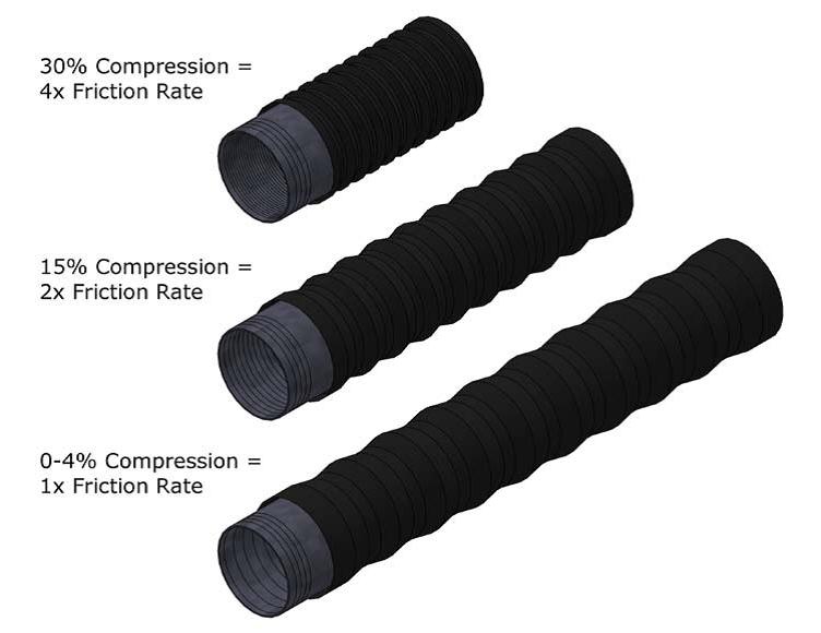
Pulling flex duct taut when installing greatly reduces the amount of friction caused by the ducting
Image
Image
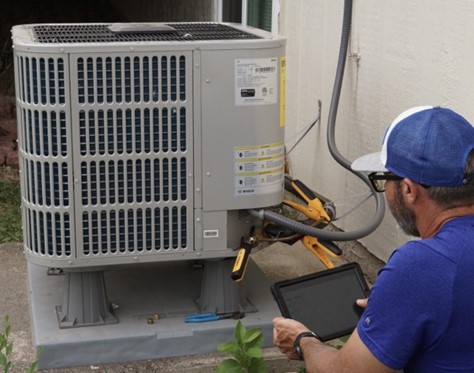
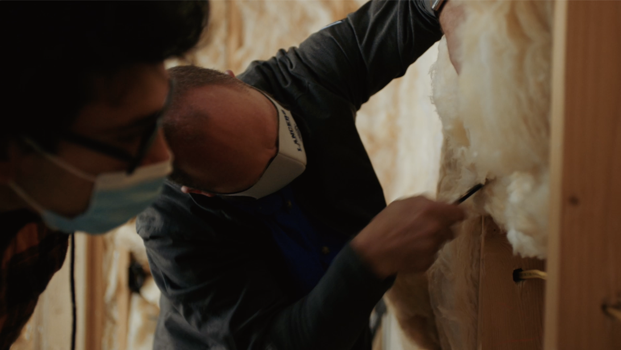
Quality installation and commissioning are critical to optimizing heat pump performance.
Image
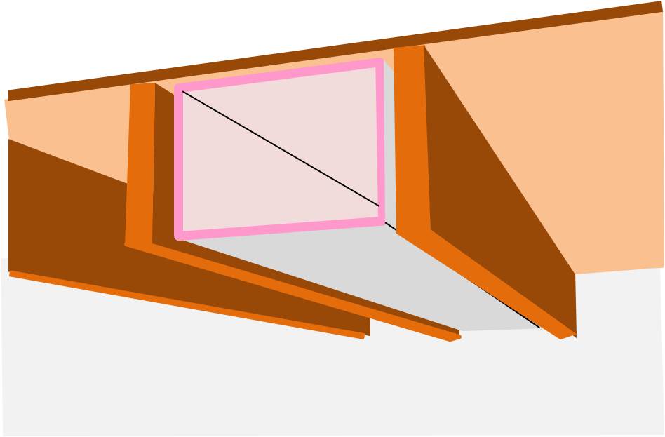
R-6 flexible duct has 2 inches of insulation around the inner liner so a 12-inch duct requires a 16x16-inch chase
Image
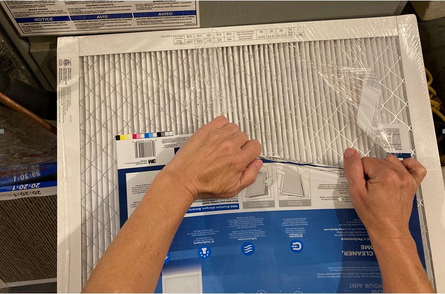
Remove the plastic wrap, but not the cardboard frame, before installing the furnace/air handler filter in the filter slot or above the return grate; note, the metal wire over the filter fabric can be very sharp.
Image
Image
Image
Image
Image
Image
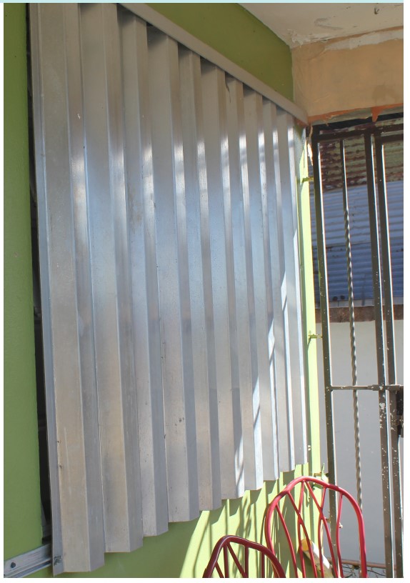
Right - Aluminum accordion coverings are permanently installed and can be deployed quickly but must be manually closed from the outside.
Image
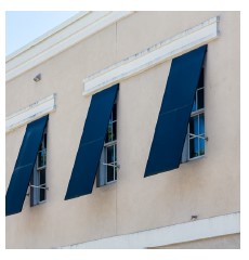
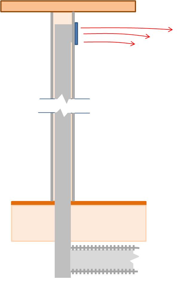
Right - Aluminum or polycarbonate panels attach to permanently mounted railings and require installation from the exterior.
Image

Right - Baffles are installed in attic to keep blown insulation from blocking soffit vents and ventilation path
Image
Image

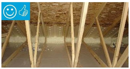
Right - Blown insulation in existing attic provides even coverage completely filling the attic space to a depth that covers the ceiling joists.
Image

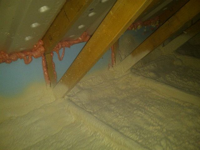
Right - Closed-cell spray foam covers the ceiling and joists to insulate and air-seal the ceiling deck.
Image
Right - Closed-cell spray foam covers the interior of the foundation wall and wall framing is placed to the inside of the spray foam.
Image
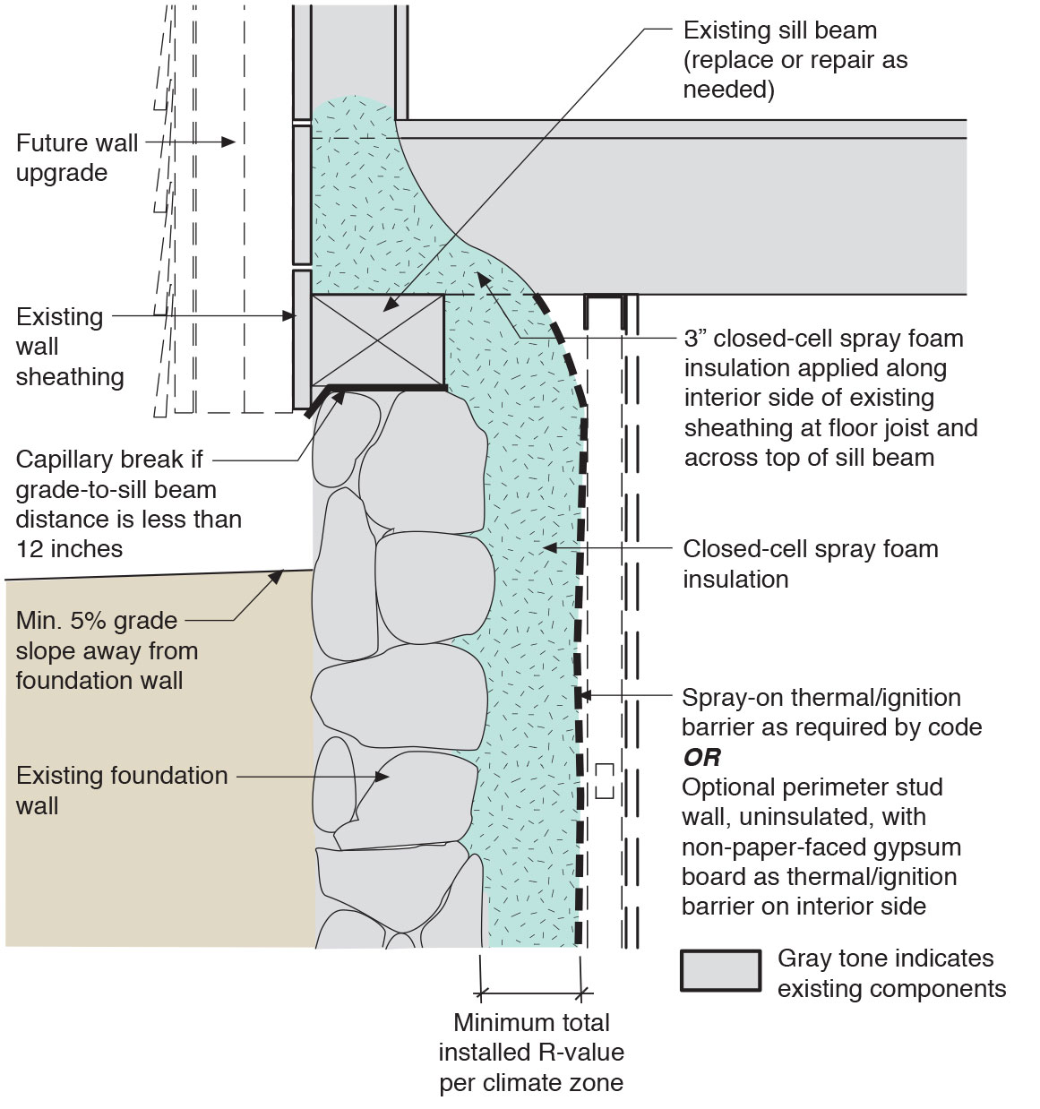
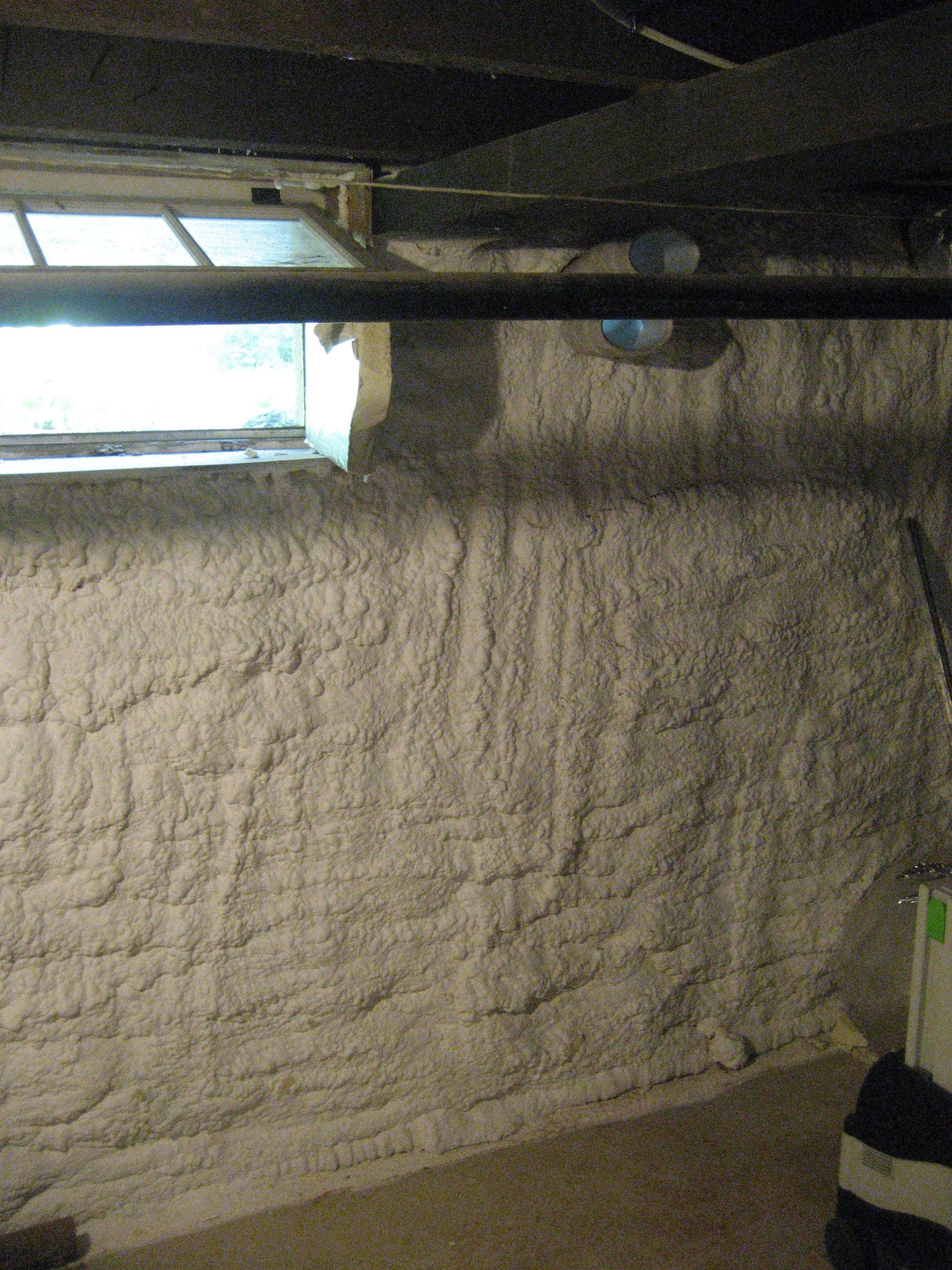
Right - Closed-cell spray foam is used to retrofit an existing rubble basement foundation wall.
Image
Right - Closed-cell spray foam was applied to the interior of a foundation wall.
Image
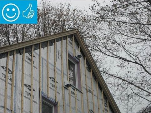
Right - Foil-faced polyisocyanurate rigid foam is attached to the existing exterior wall with vertical wood furring strips
Image
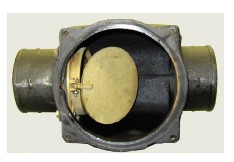
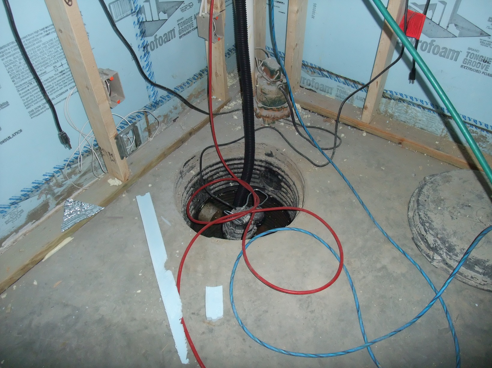
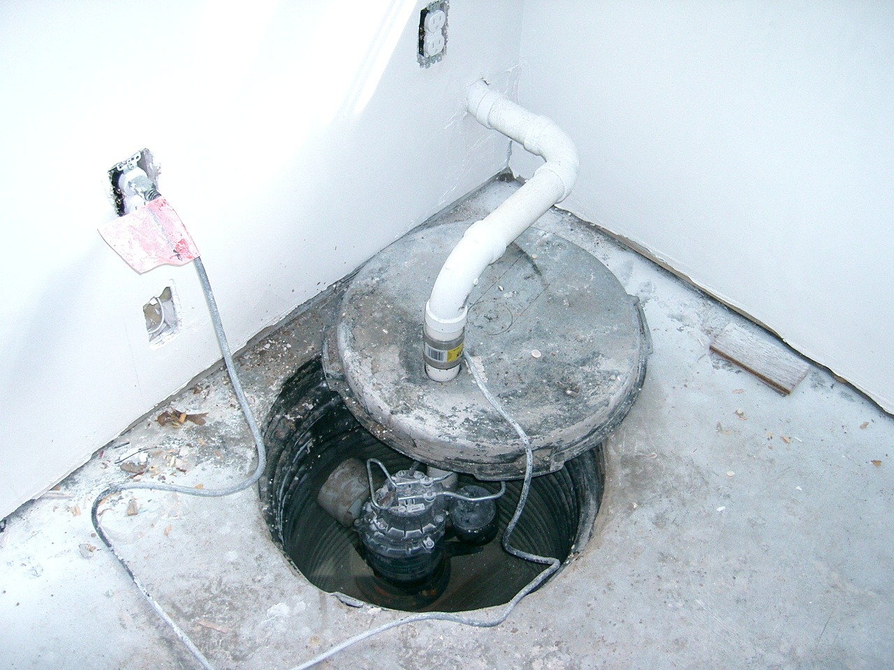
Right - Install backflow prevention devices on plumbing pipes to prevent wastewater from entering the home's plumbing system.
Image
Right - Panels of 7/16-inch treated plywood are inexpensive but take time to install and are difficult to install on higher windows.
Image
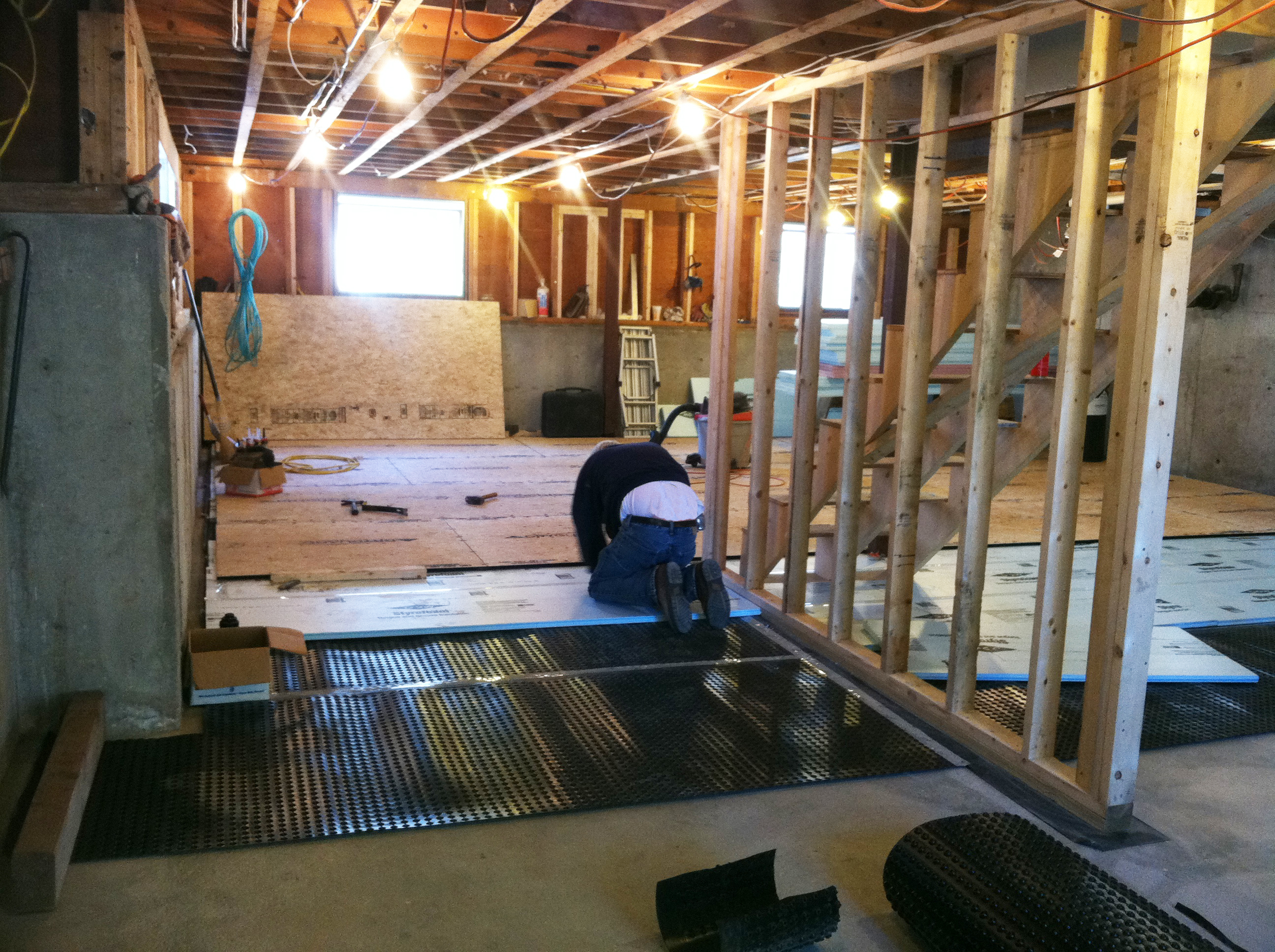
Right - Retrofit of an existing basement slab by adding dimple plastic mat, rigid foam insulation, and a floating subfloor.
Image
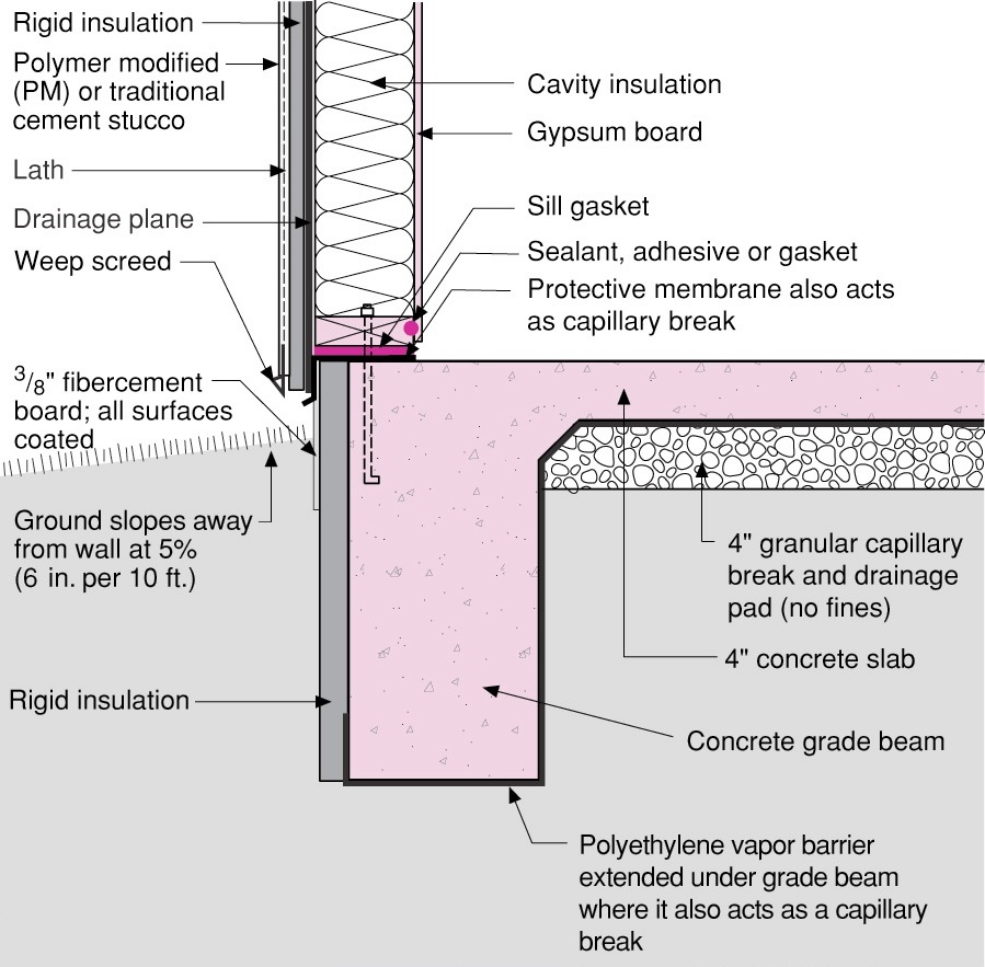
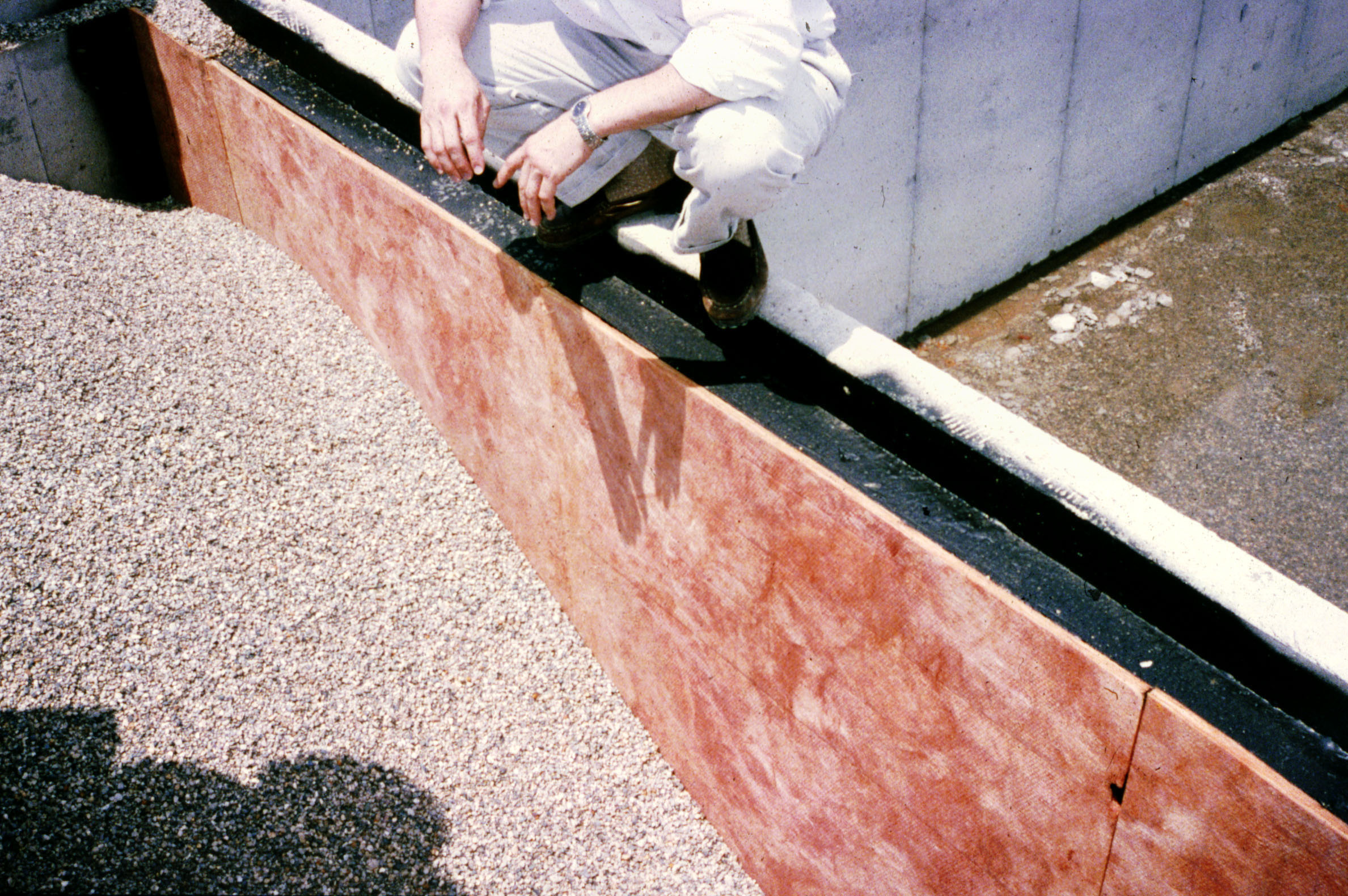
Right - Rigid foam slab edge insulation is installed along the exterior edge of a monolithic slab foundation.
Image
Right - Spray foam insulation air-seals the ceiling-to-drywall seams at the wall top plate.
Image
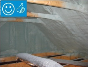
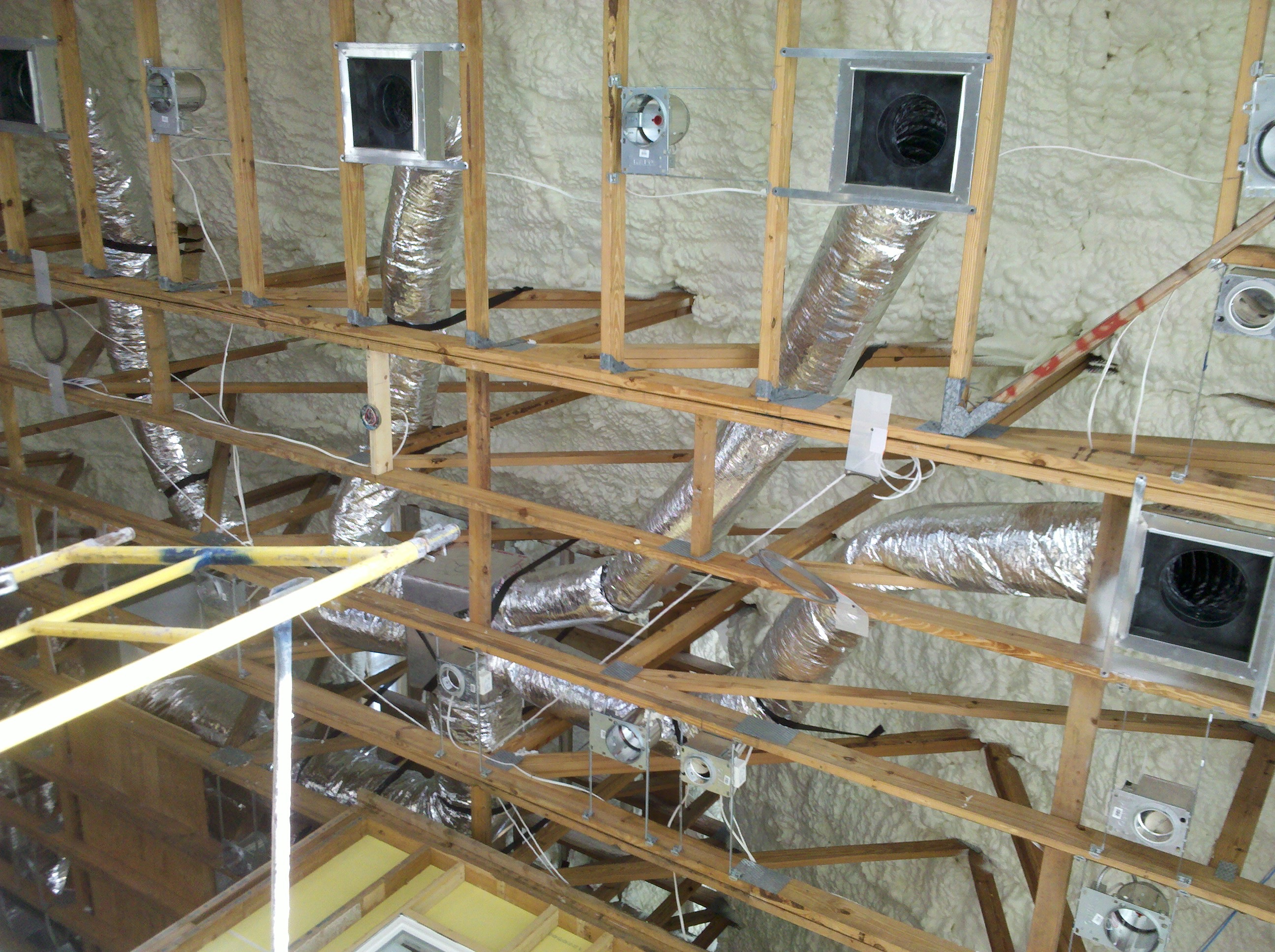
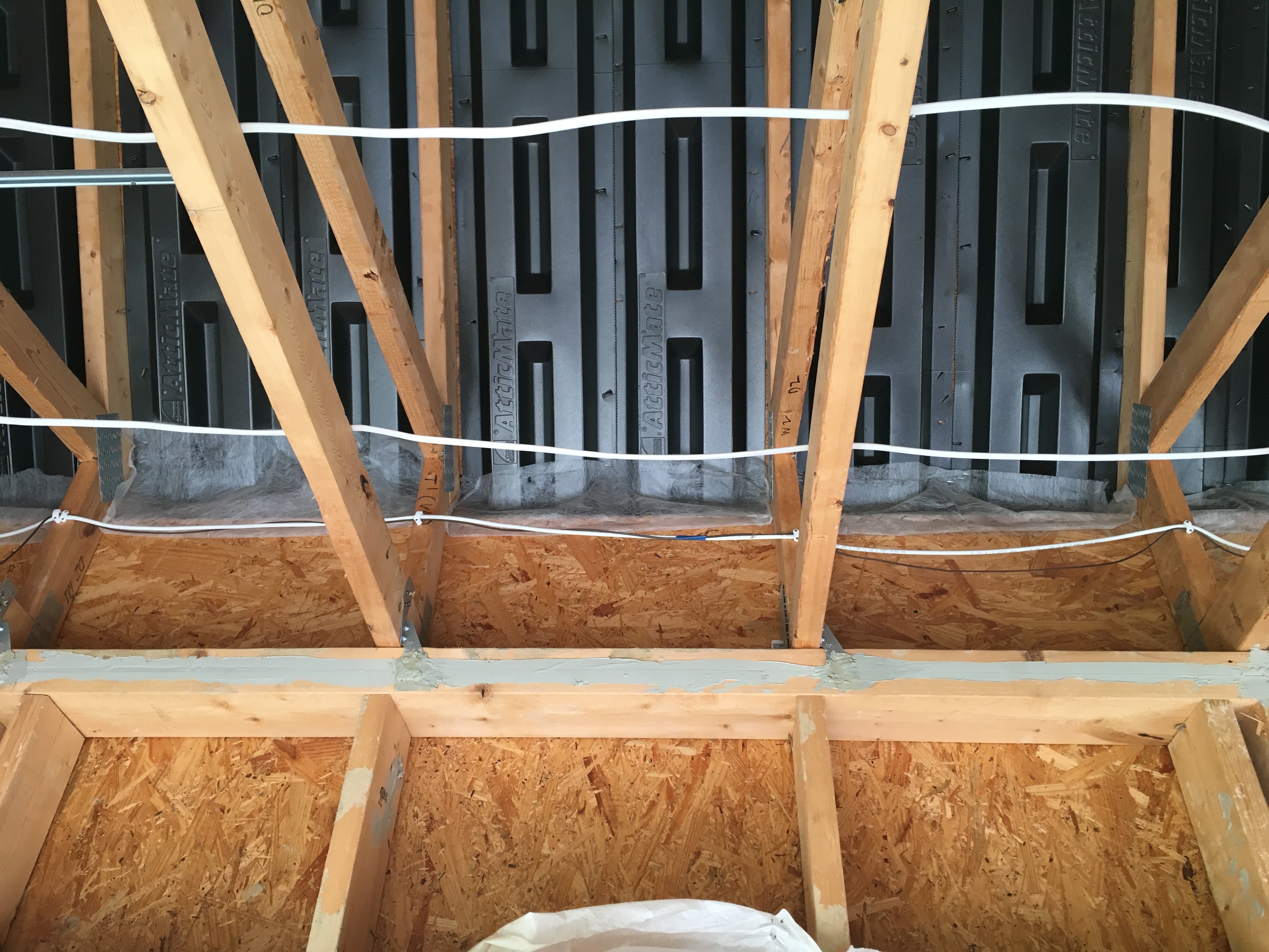
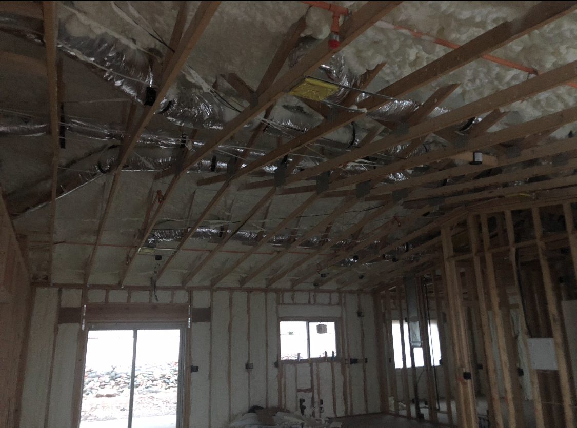
Right - Spray foam insulation has been sprayed onto the underside of the sloped roof and the gable end wall to provide a sealed, insulated attic for housing the HVAC ducts
Image

Right - The wall top plates are sealed with foam before installing insulation on the ceiling deck.
Image
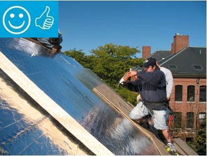
Right - These roof insulation panels are installed in multiple layers with joints offset both vertically and horizontally. The plywood nail base fastened to the roof framing holds the insulation layers together snuggly thus minimizing gaps
Image
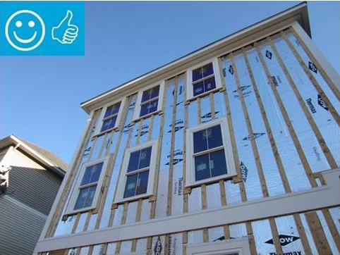
Right - This foil-faced polyisocyanurate rigid foam is installed on an existing exterior wall and the seams are taped so the rigid foam can serve as a water control layer
Image
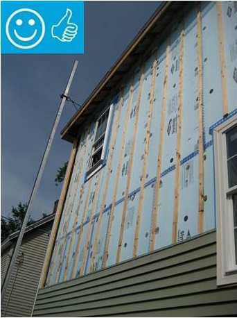
Right - XPS foam insulation is attached to the existing exterior wall with wood furring strips that serve as a nail base for the siding and are installed vertically to allow for drainage and drying behind the siding
Image
Right – an instructor shows a student how to cut batt insulation around wiring rather than compressing the batt behind the wiring.
Image
Image
Image
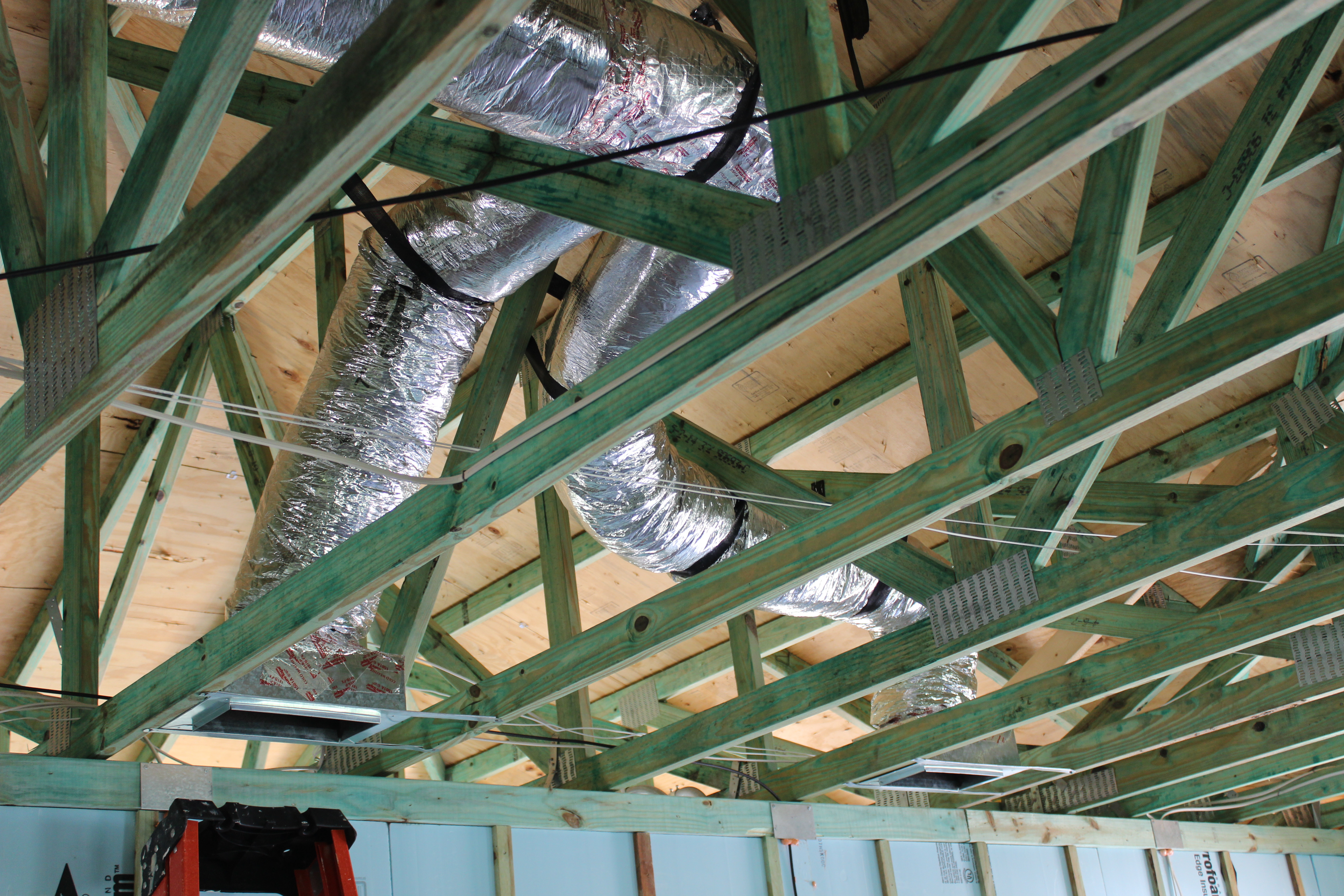
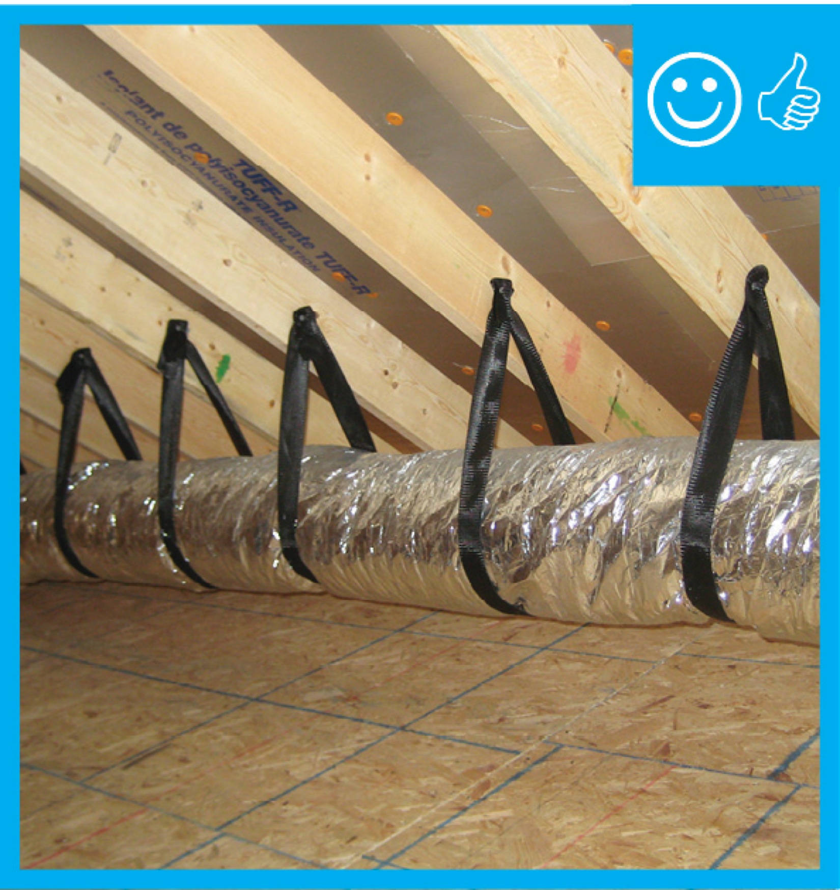
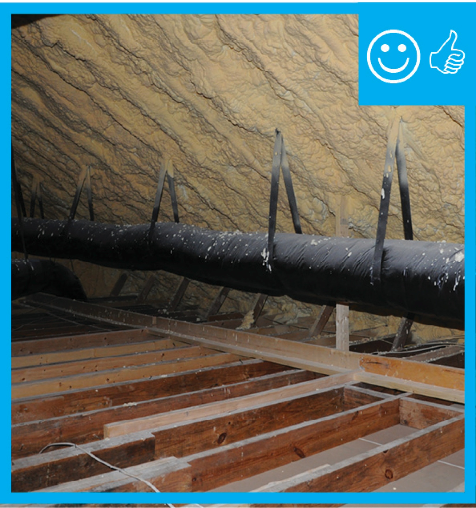
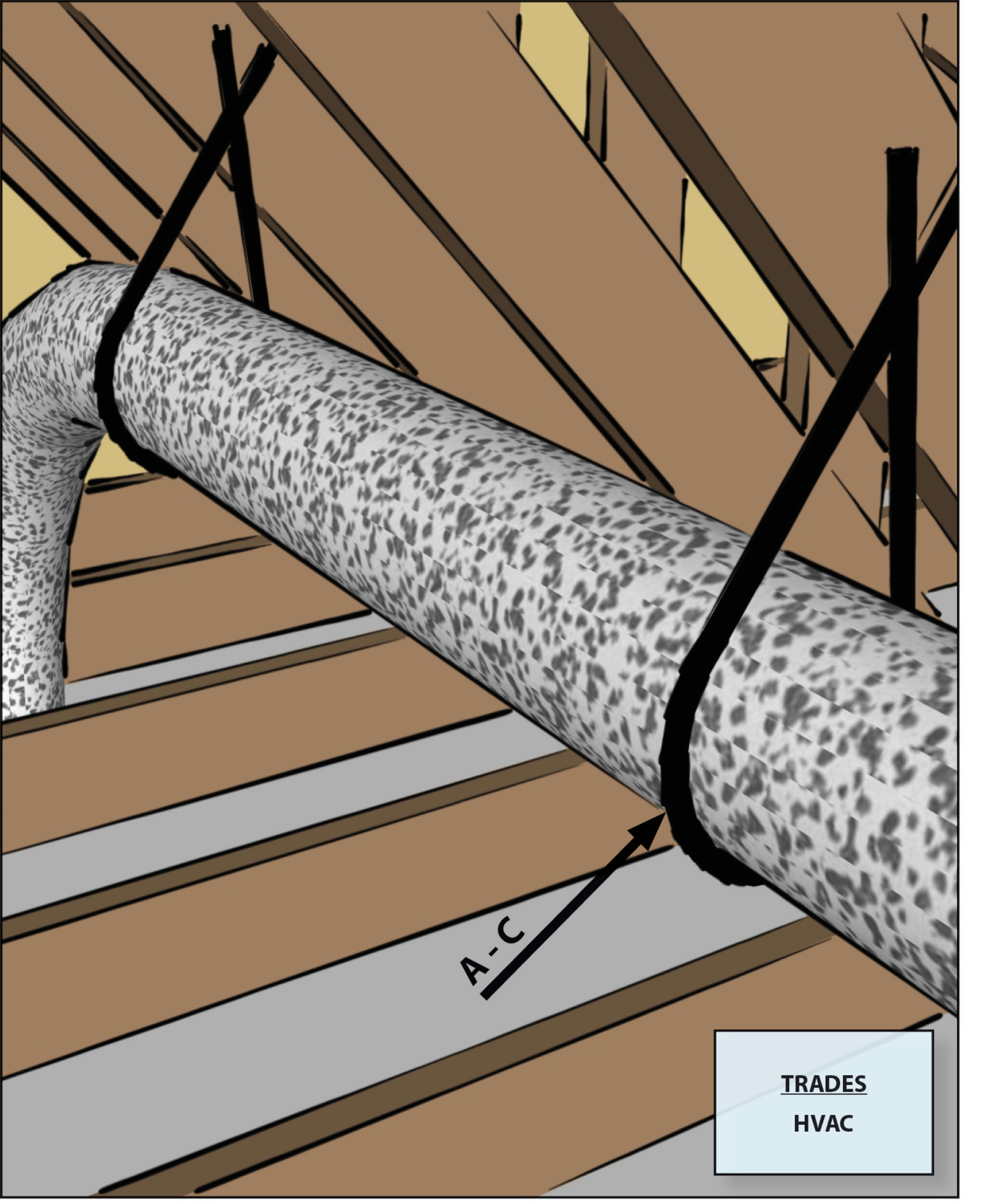
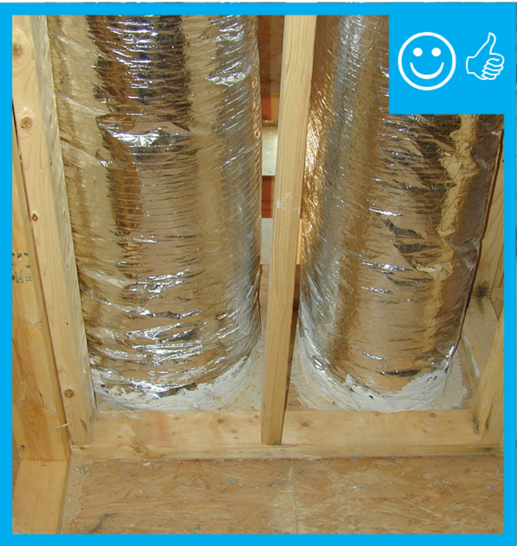
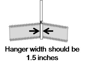
Right – Flex ducts are properly supported with straps that don’t pinch the insulation; closed-cell spray foam will be applied to the underside of the roof deck of this hot-humid climate home to provide an insulated attic space for the HVAC ducts.
Image

Image
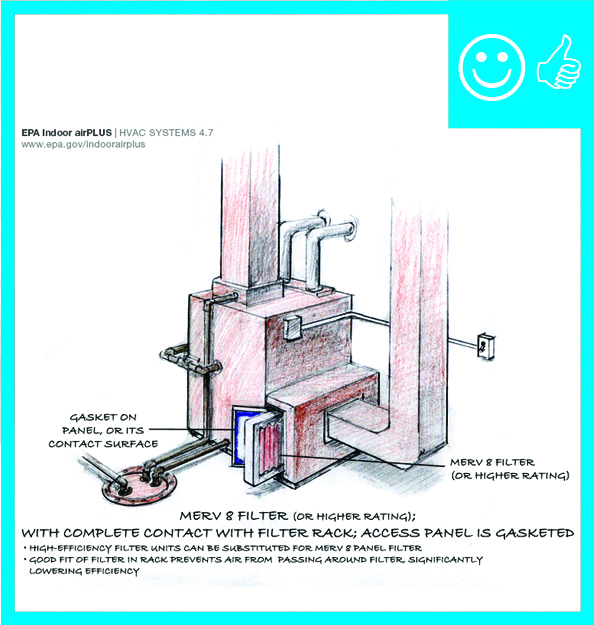
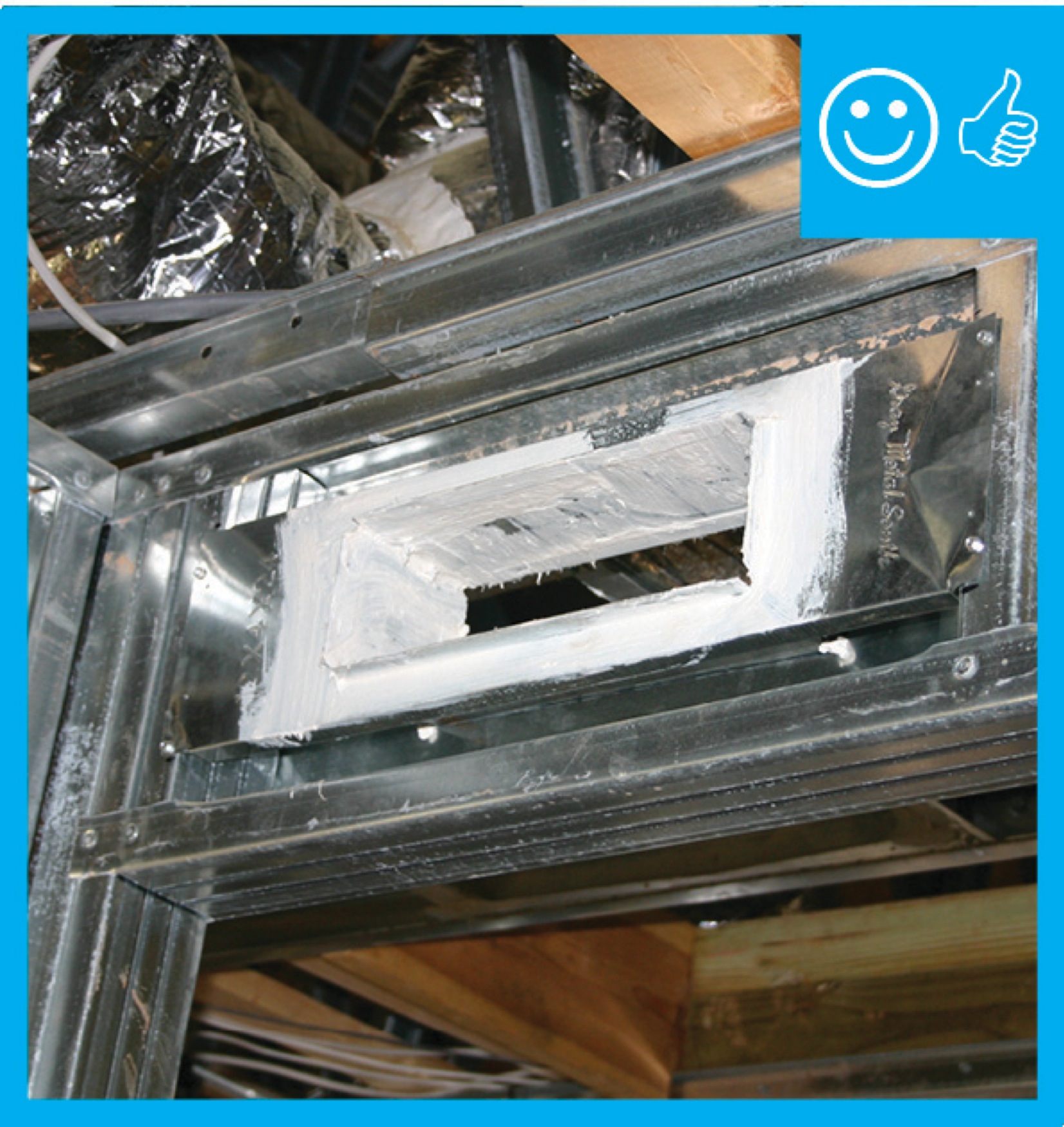
Right – HVAC furnace filter is properly installed in cabinet with gasketed cover to prevent air leakage
Image
Image
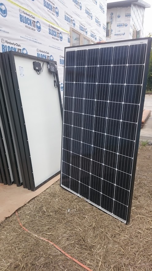
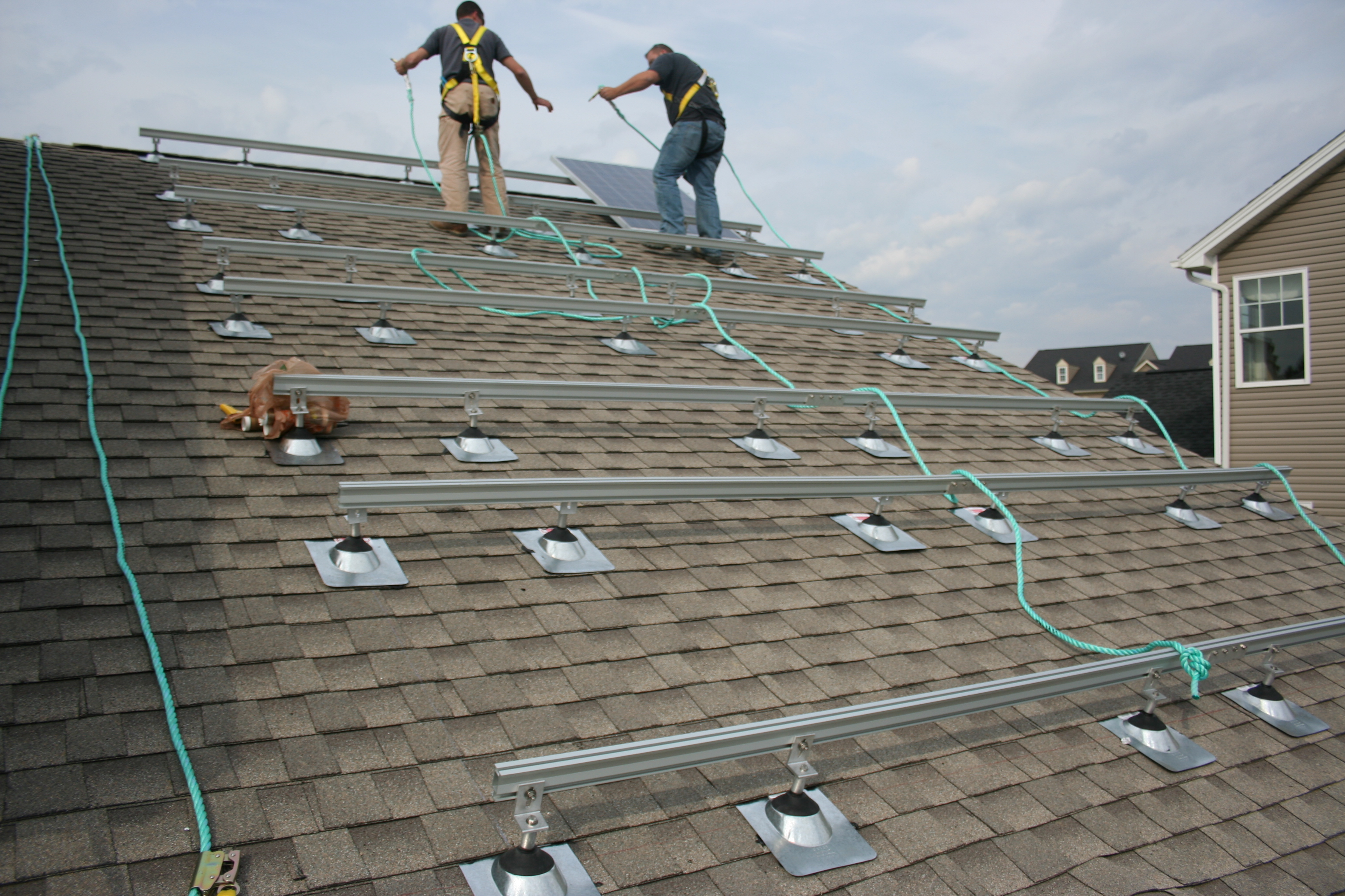
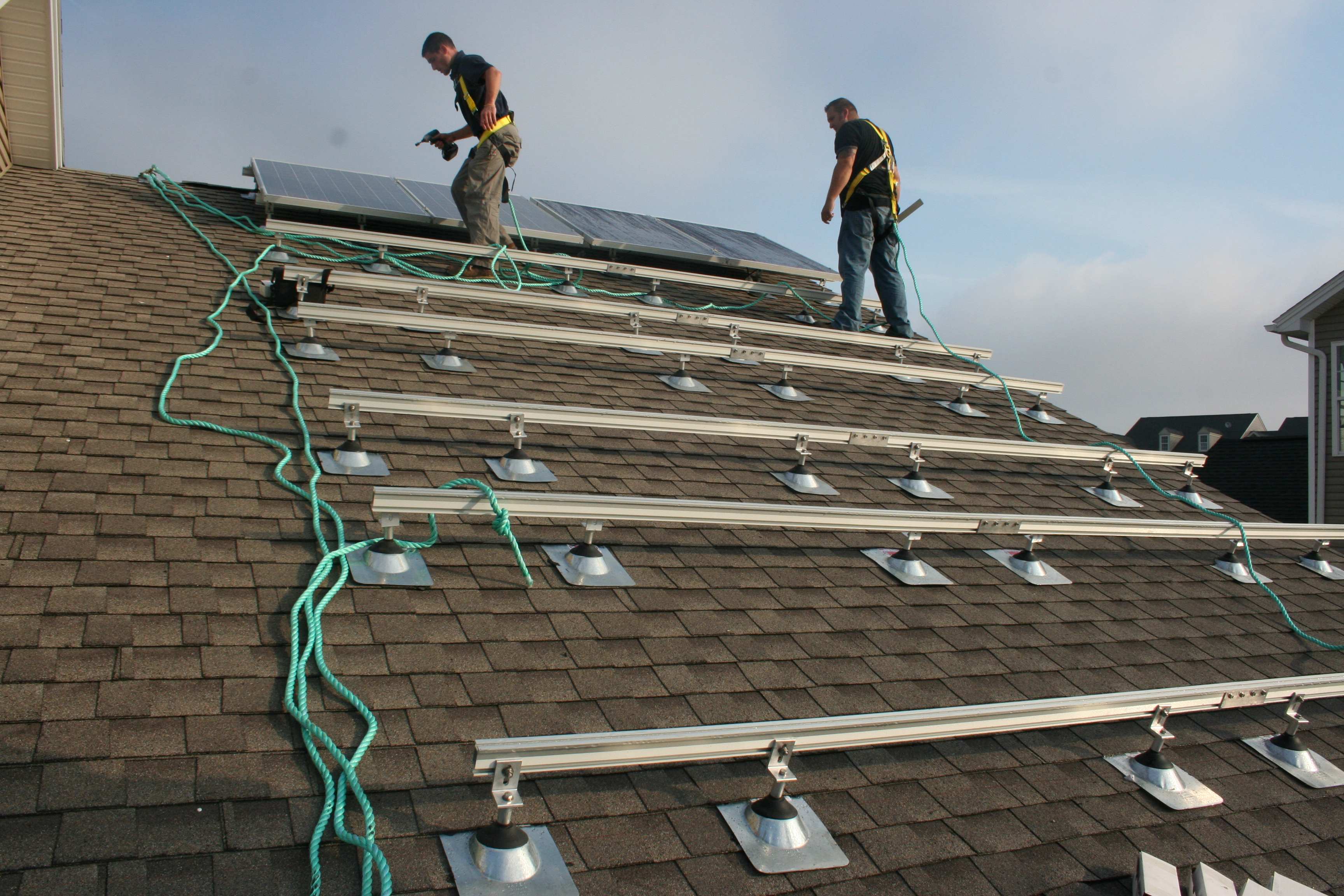
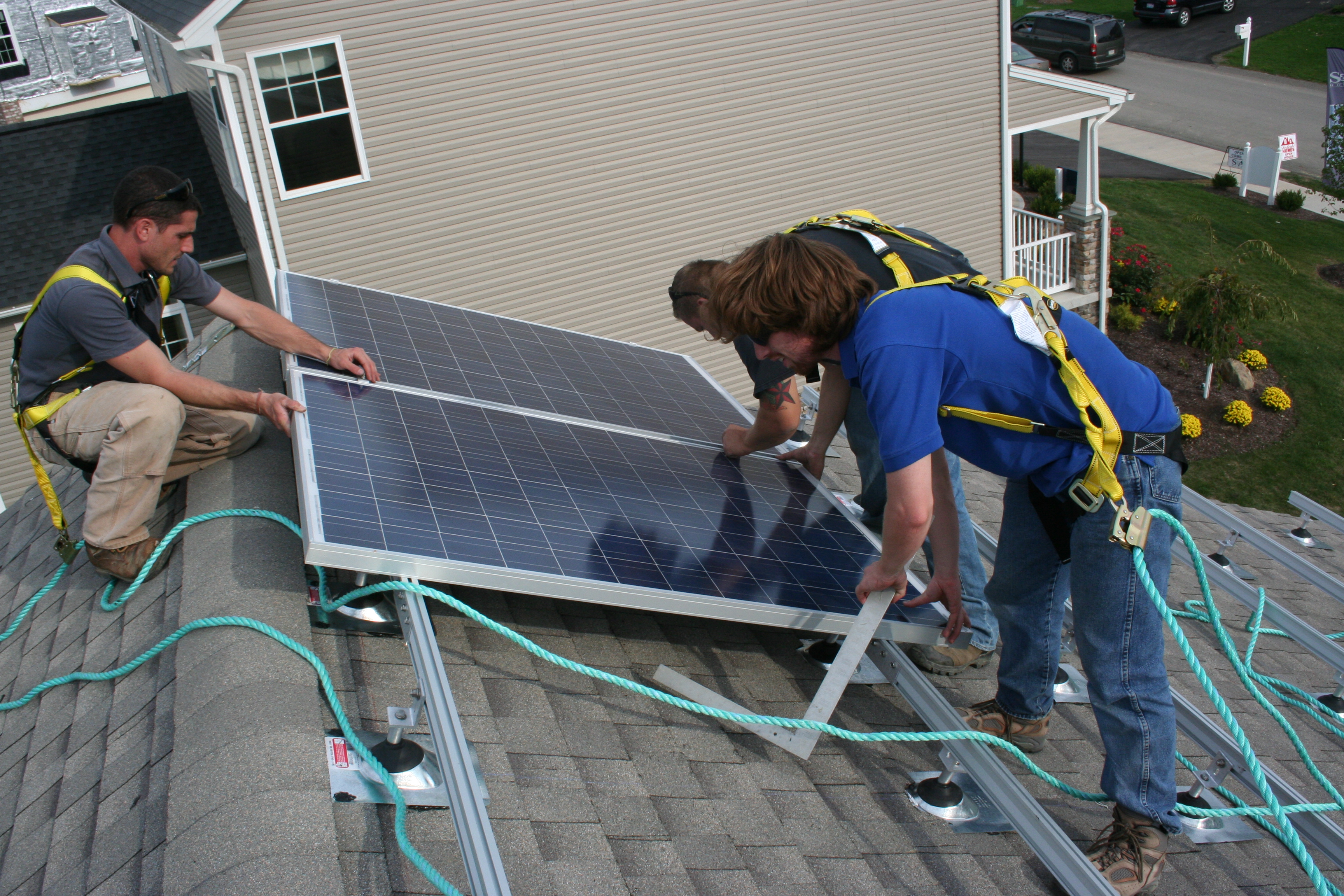
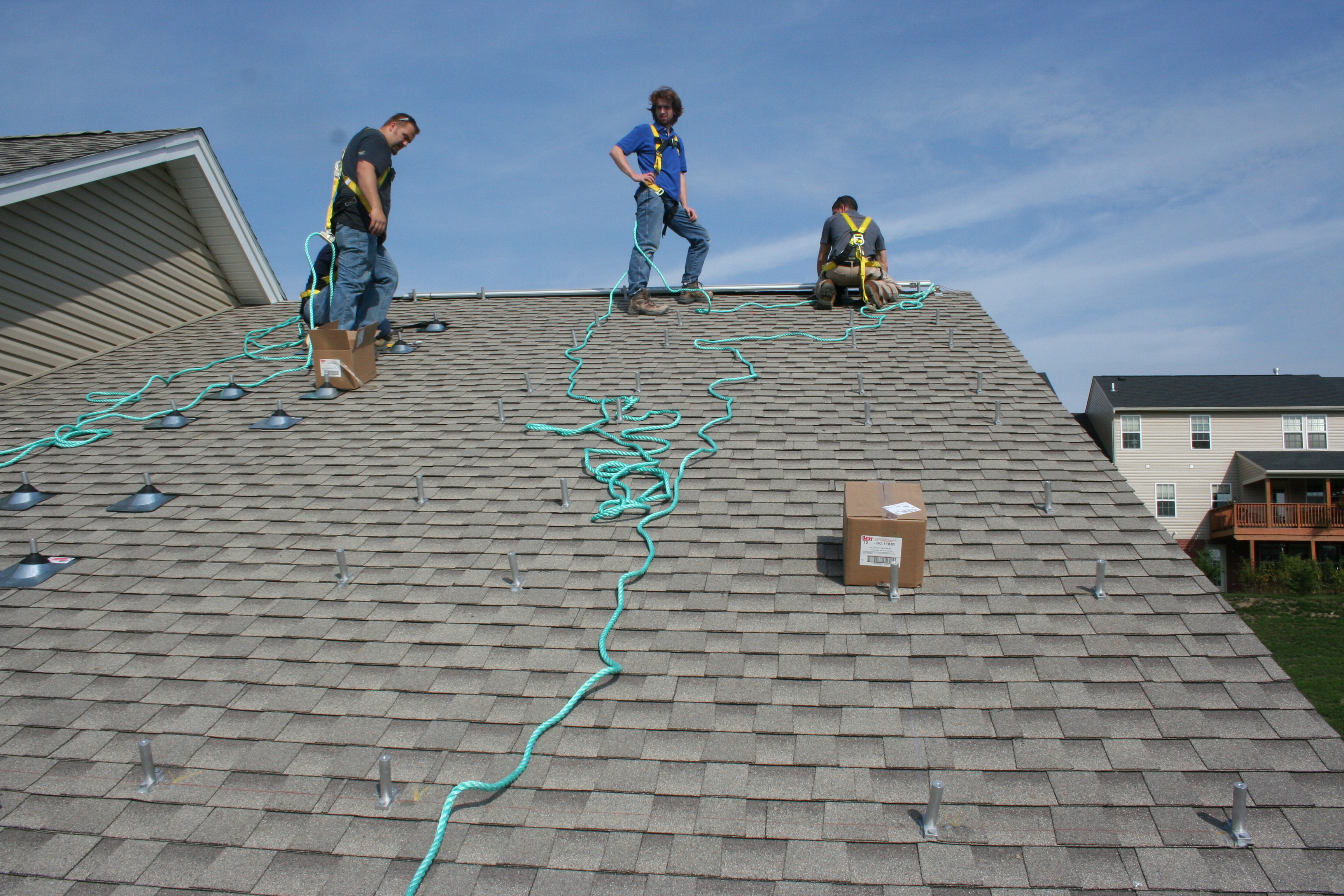
Right – Photovoltaic solar panels are ready for installation on the roof of a DOE Zero Energy Ready certified home.
Image
Image
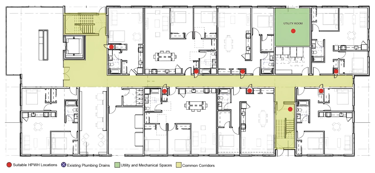
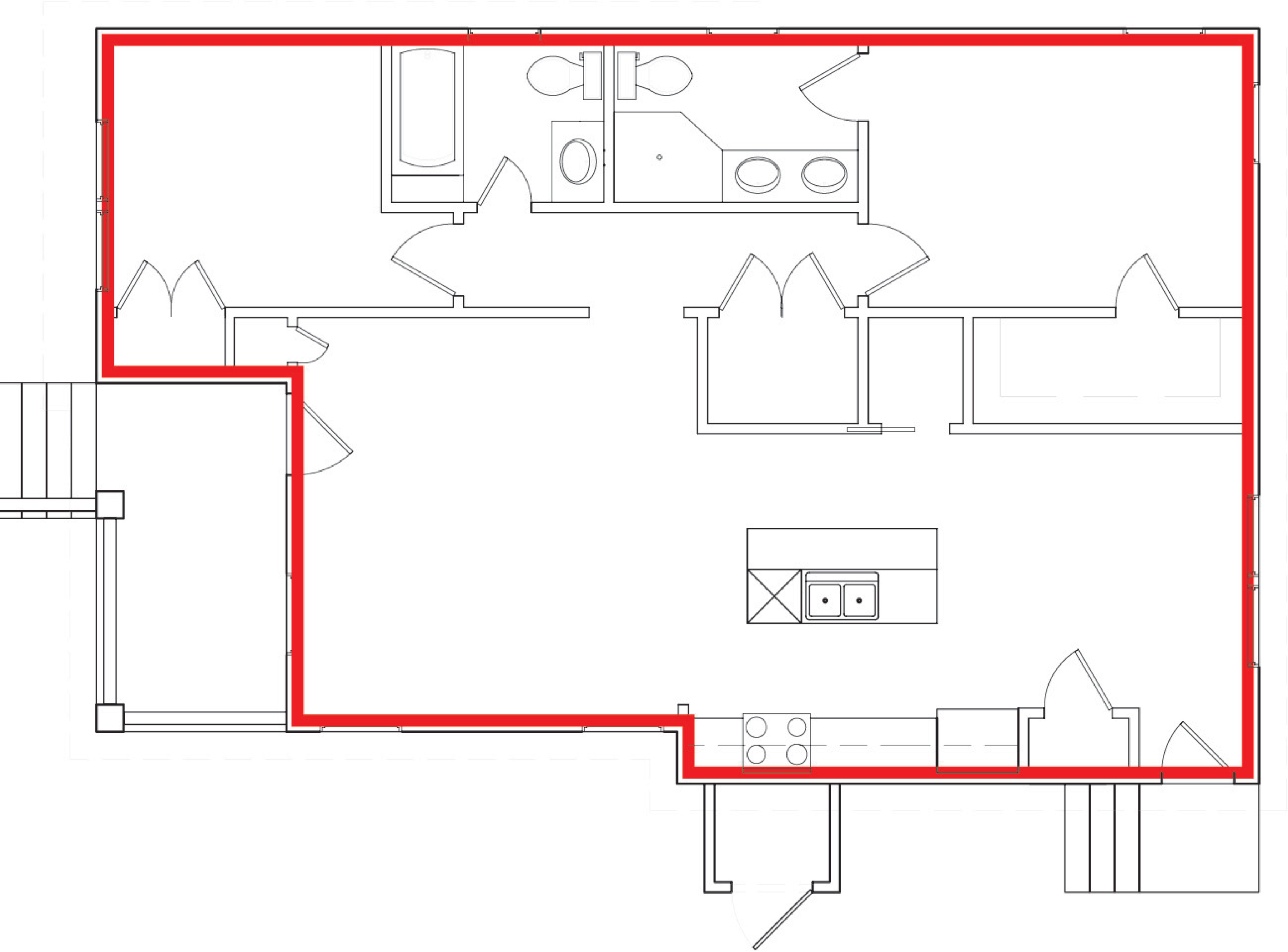
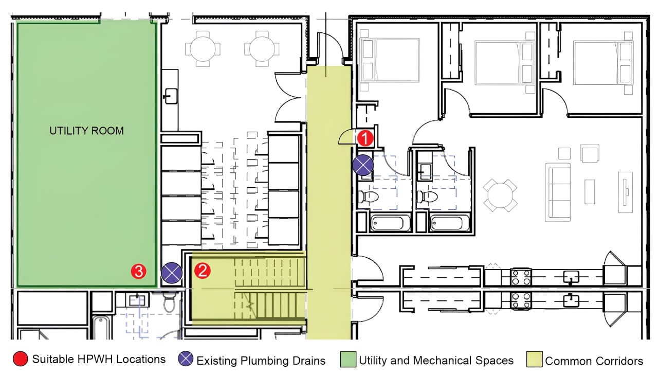
Right – Possible Heat Pump Water Heater Locations on a Multifamily Floorplan including an interior corridor, eight apartments, and meeting rooms
Image
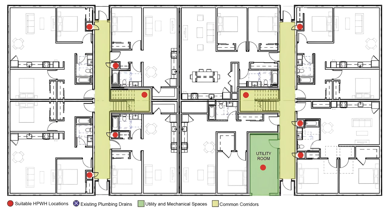
Right – Possible Heat Pump Water Heater Locations on a Multifamily Floorplan including interior corridor closets, under-stair closes, and utility rooms
Image
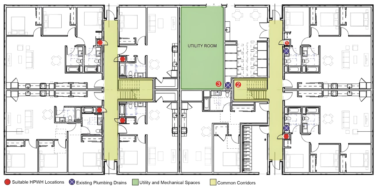
Right – Possible Heat Pump Water Heater Locations on Full Plate Floorplan in a Multifamily Building
Image
Image
Image
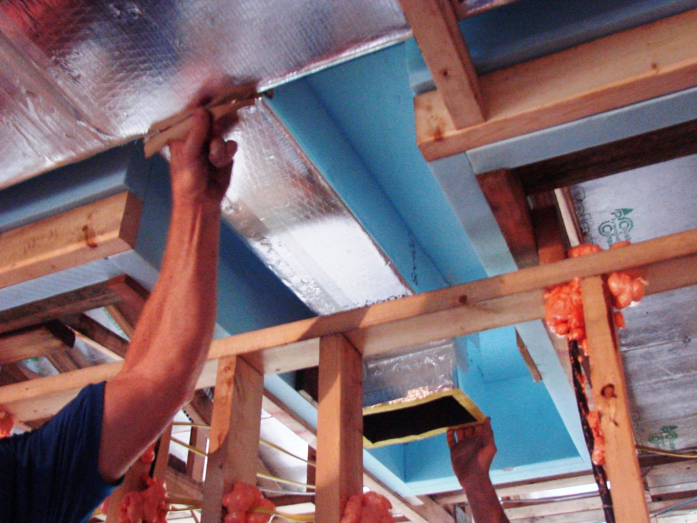
Right – Spray foam insulation is sprayed on the underside of the roof deck to provide a conditioned space in this low attic for the HVAC ducts.
Image
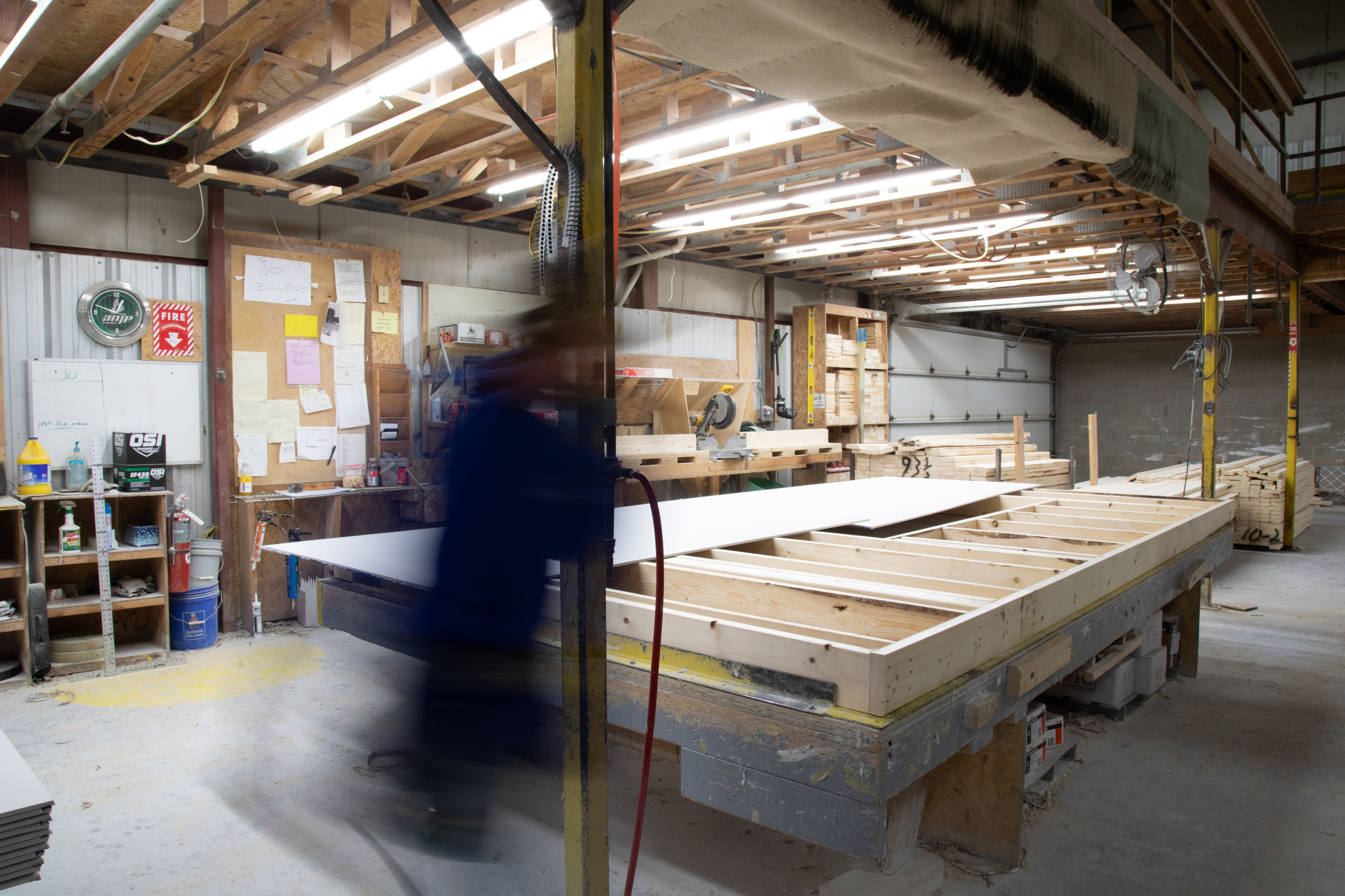
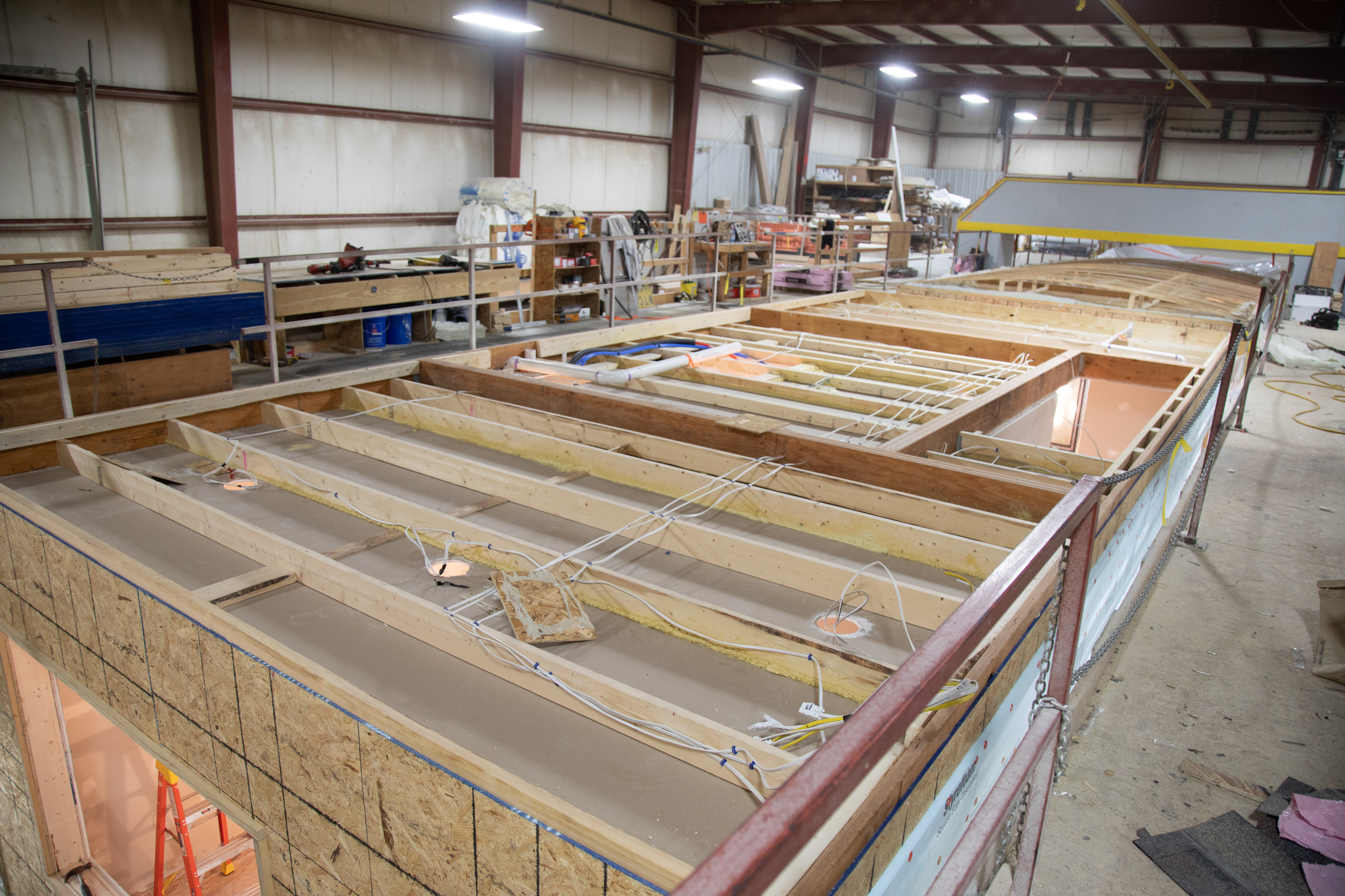
Right – Subfloors are installed in a clean, dry, well-lit factory setting for these modular, factory-built homes.
Image
Right – The walls of this home were constructed with “insulated studs” fashioned on site by adding 2-inch-thick strips of rigid foam to the inside face of 2x4 studs then topping that with a plywood nailing surface.
Image

Right – This attic knee wall and the floor joist cavity openings beneath it are being sealed and insulated with spray foam.
Image
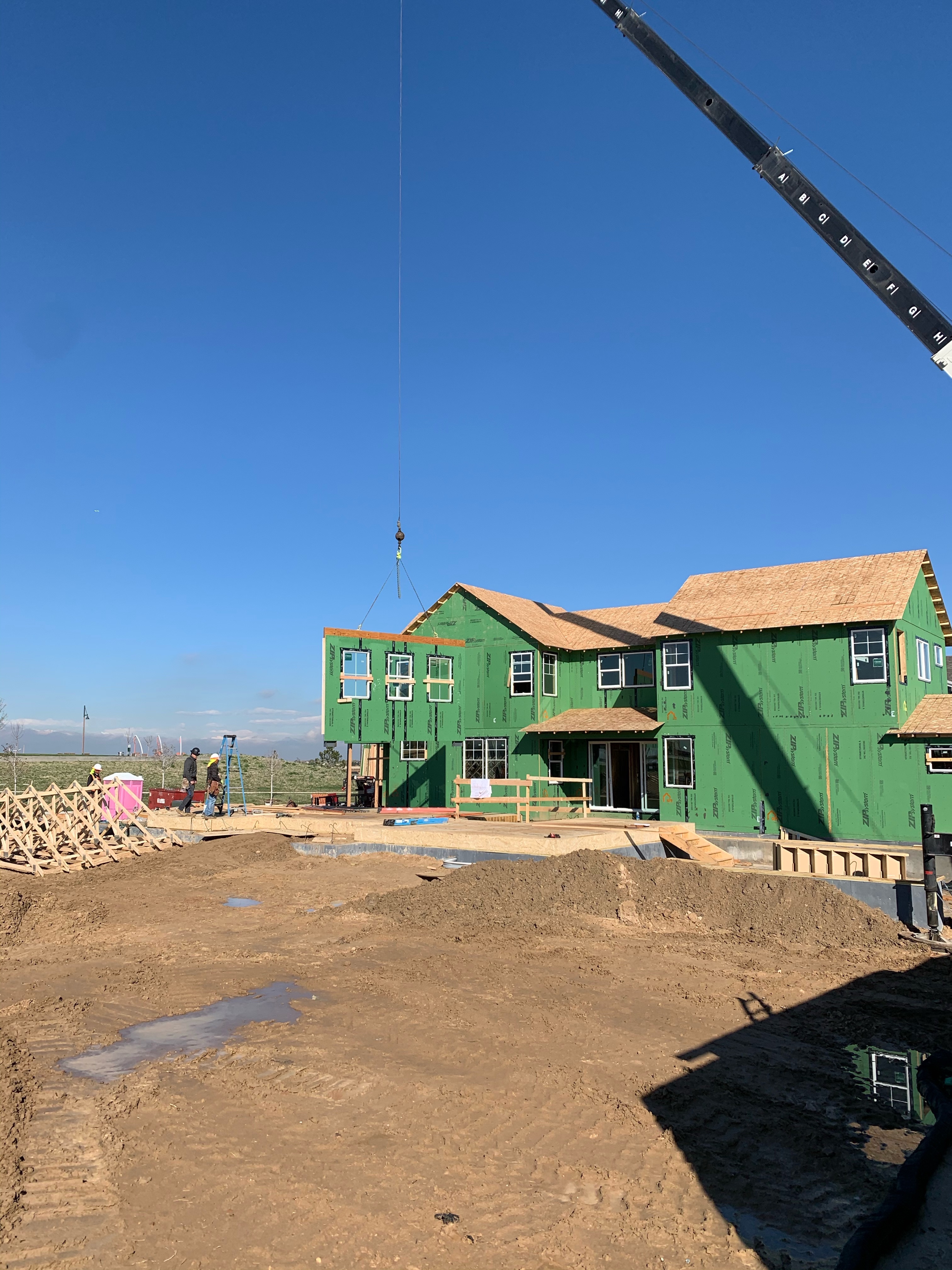
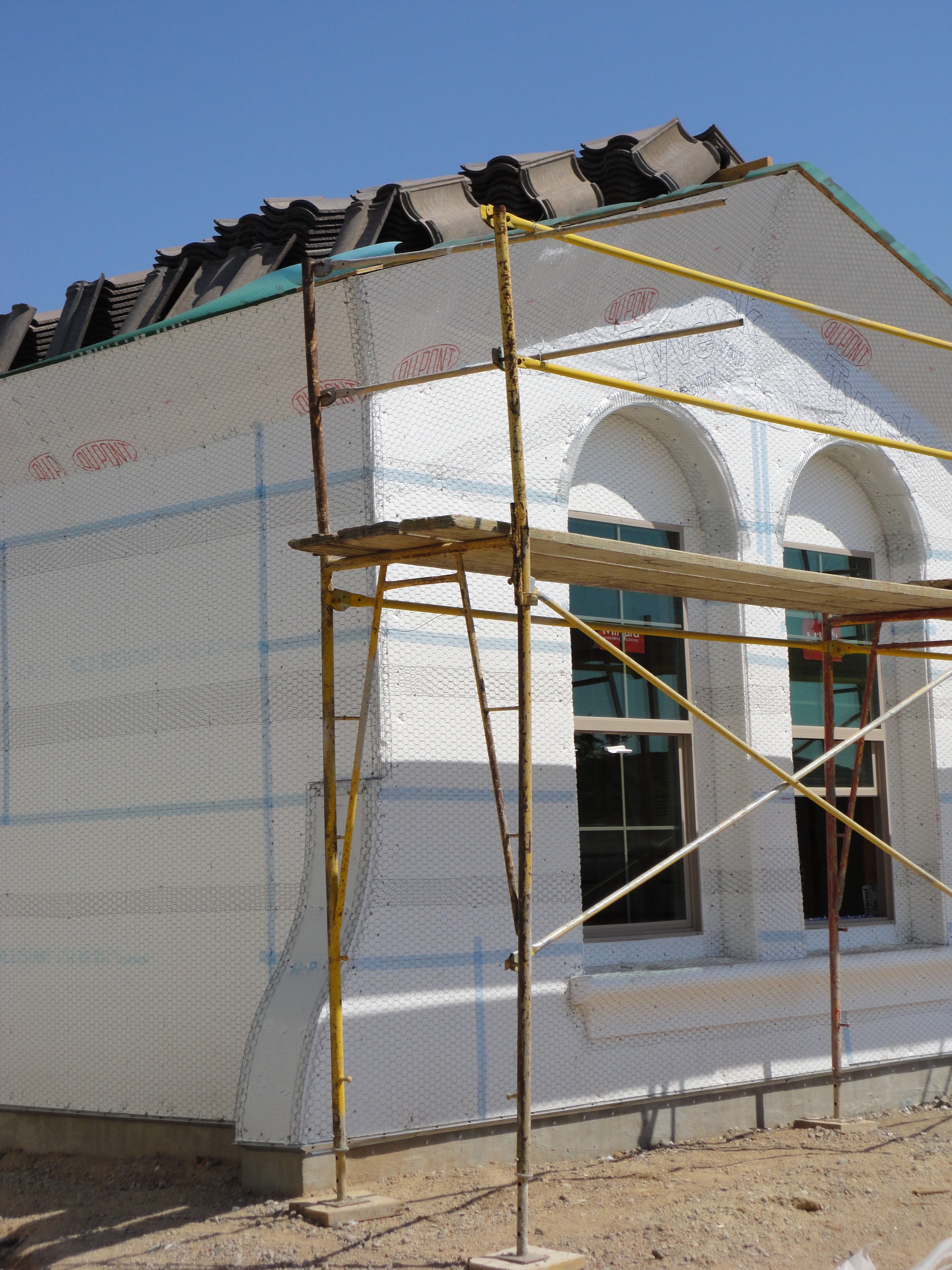
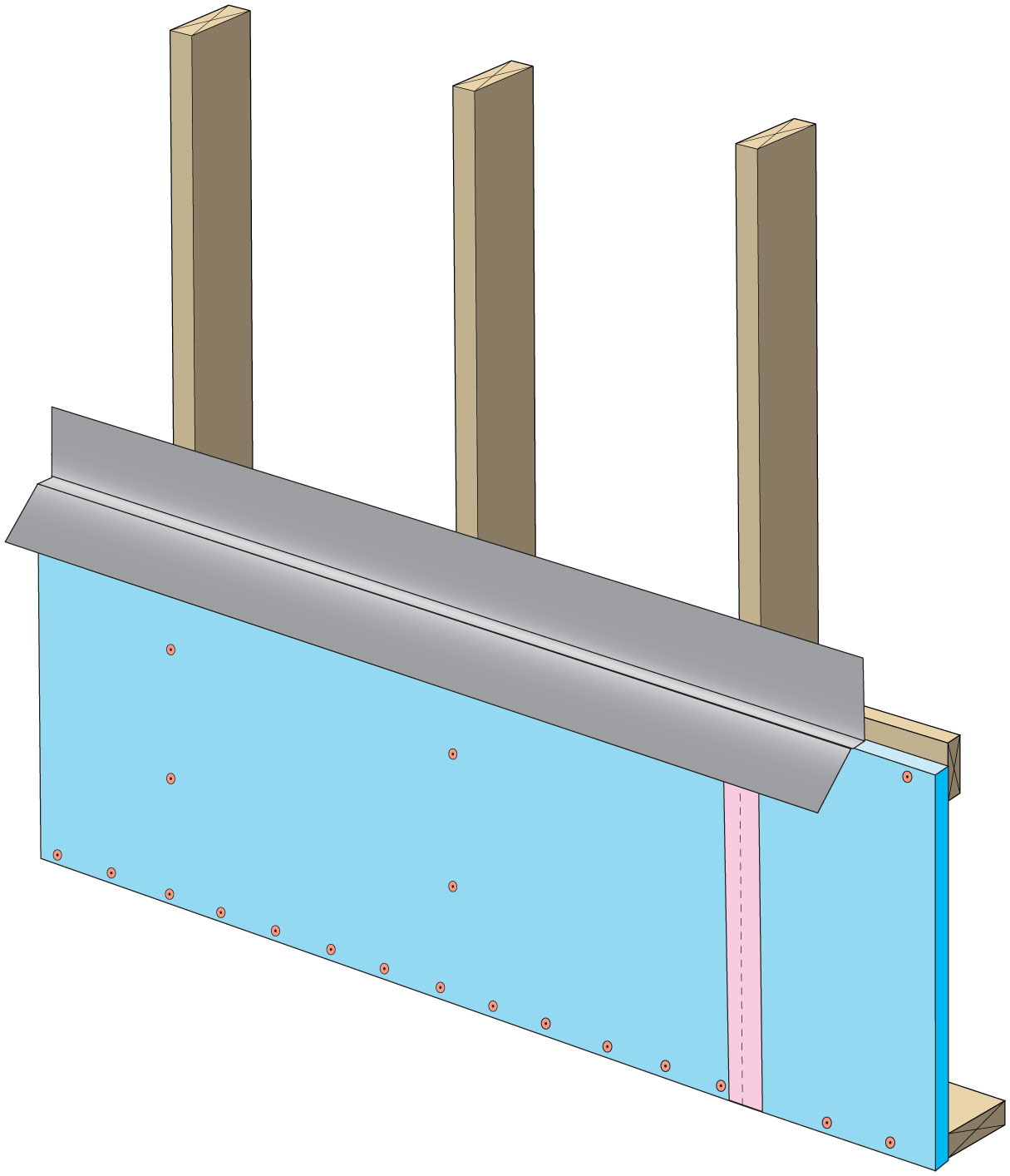
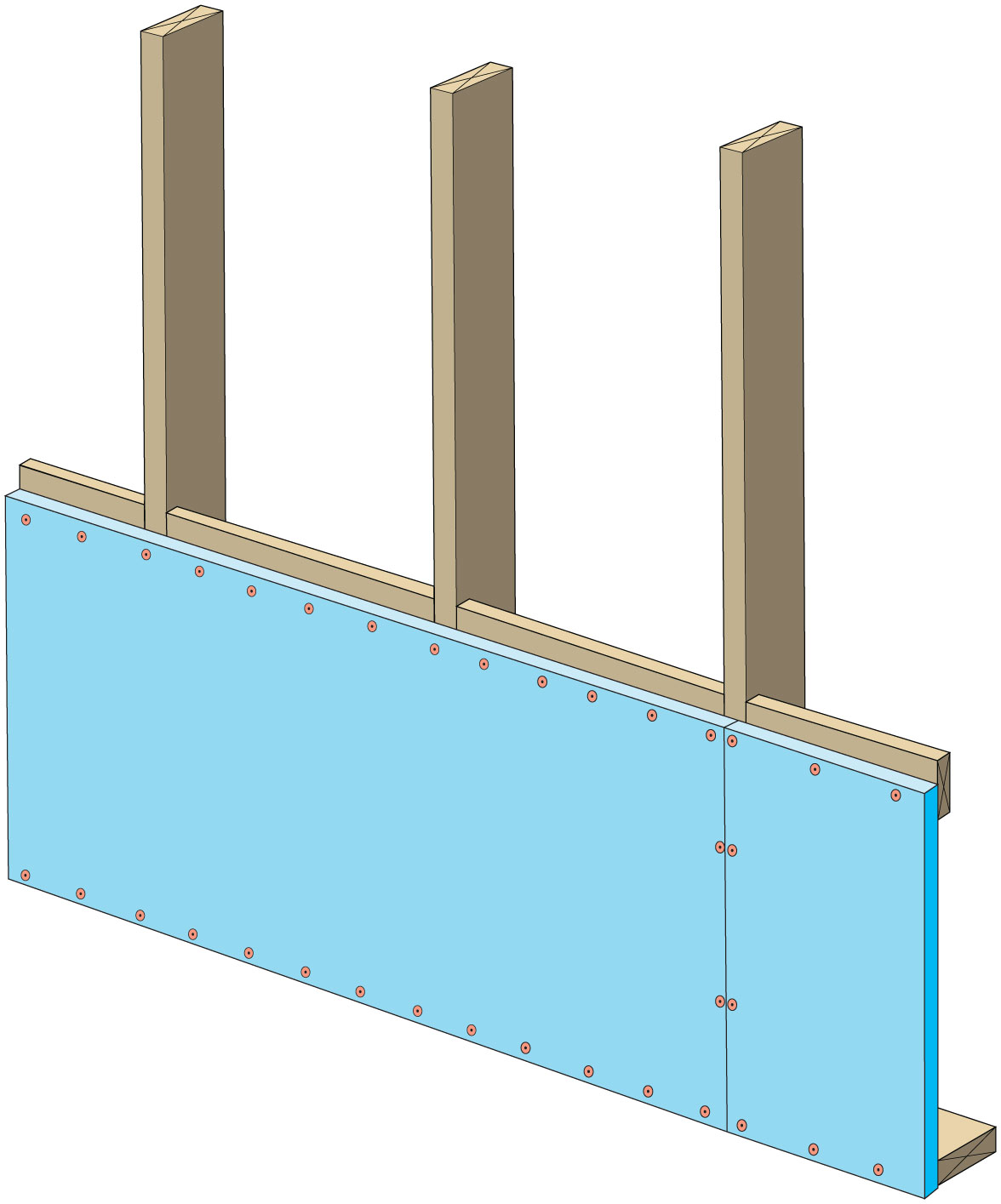
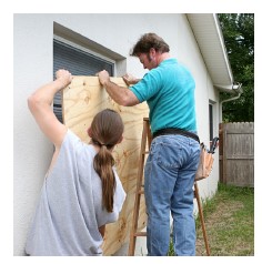
Right – This home’s above-grade walls are constructed in a factory where wall panels of 2x6 studs are assembled and sheathed with a coated OSB product, then windows are installed and flashed before shipping the panels to the site for assembly by crane.
Image
Right – Walls, windows, and wiring are installed in the factory for these modular homes, which are installed at the site on basement foundations made of insulated concrete wall panels.
Image
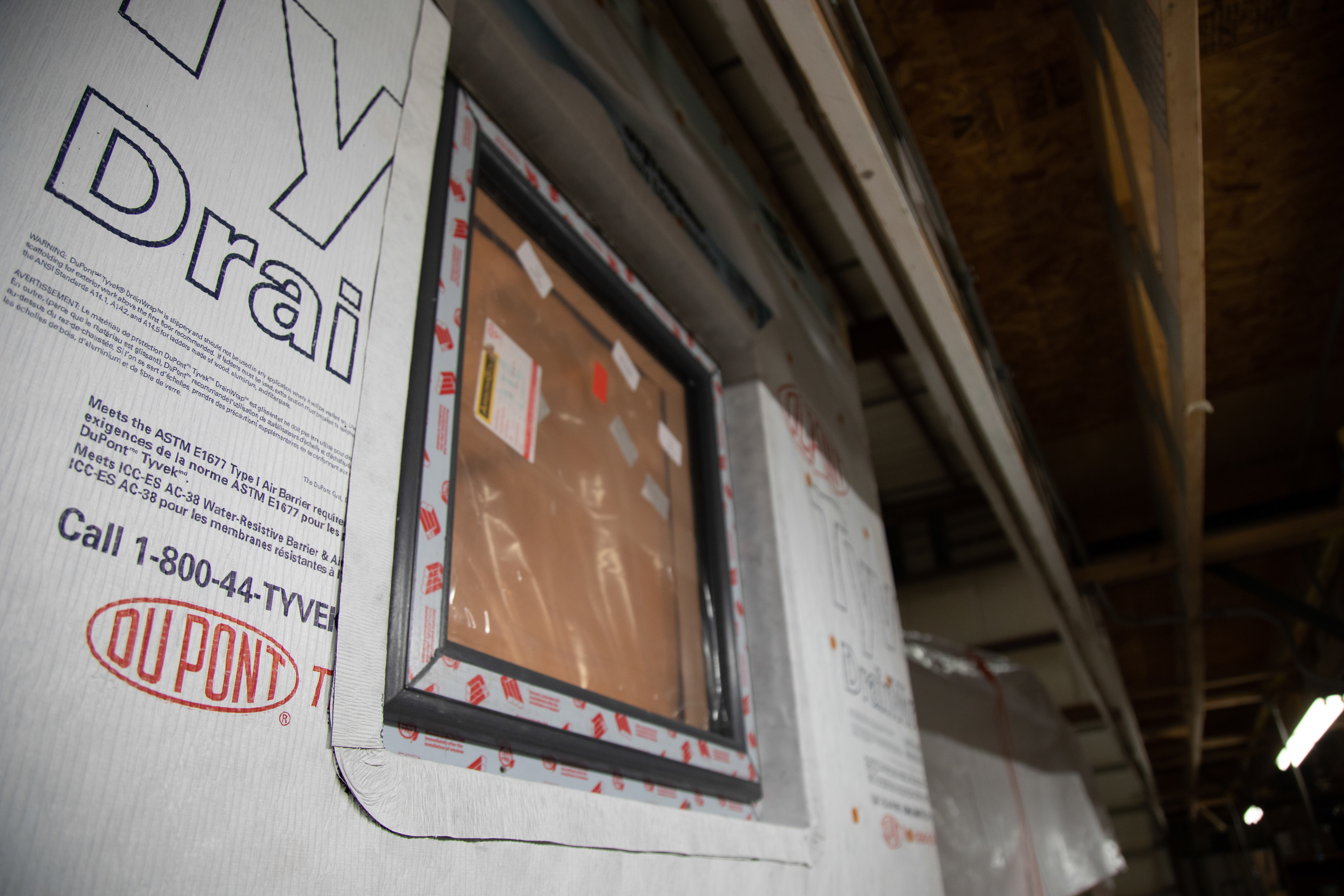
Right – Windows are installed and flashed in the factory for these modular homes.
Image
Right-- IR photo shows how effectively spray foam insulated/air sealed attic kneewall and the floor cavities under kneewall
Image
Right--The polyethylene ground cover for this insulated crawlspace is taped at seams and around posts before the insulation and slab are installed.
Image
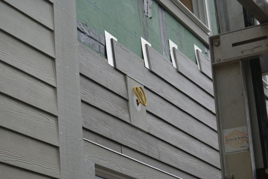
Right: Flashing the butt joints in lap siding installations is a better practice than relying on caulk to seal the joints.
Image
Right: Maintenance valves are installed at the inlet and outlet of this central heat pump water heater
Image
Right: This heat pump water heater is in a basement within the thermal boundary but not actively conditioned. It has over 770 ft² of space with easy access to the control panel and clearance for airflow to the air intake (top) and exhaust (side)
Image

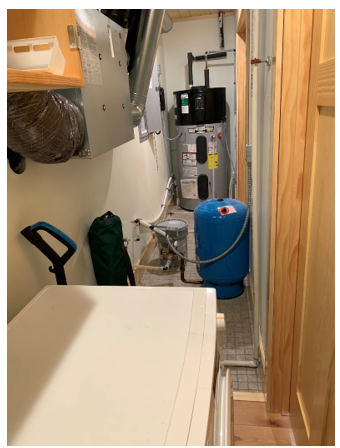
Right: This heat pump water heater is installed in a small space so the, intake air is ducted from an adjacent room; the water heater since on a pad of foam insulation and has a good drain line configuration but the waterpipes lack insulation
Image
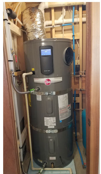
Right: This heat pump water heater is installed in a utility closet where it can use heat from the clothes washer and heat pump clothes dryer and has access to a floor drain for condensate
Image

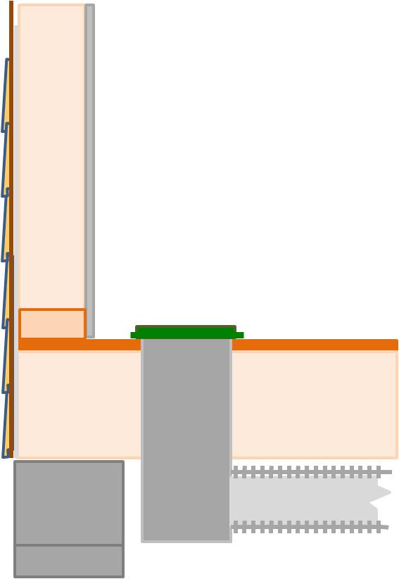
Rigid foam forms an insulating bond break between the foundation wall and the slab
Image
Rigid foam insulating sheathing installed over an existing garage ceiling with retrofits to air seal exterior wall before adding exterior wall insulating sheathing
Image

Rigid foam insulating sheathing is installed on existing garage ceiling and covered with a new gypsum board fire protection layer installed over the foam.
Image
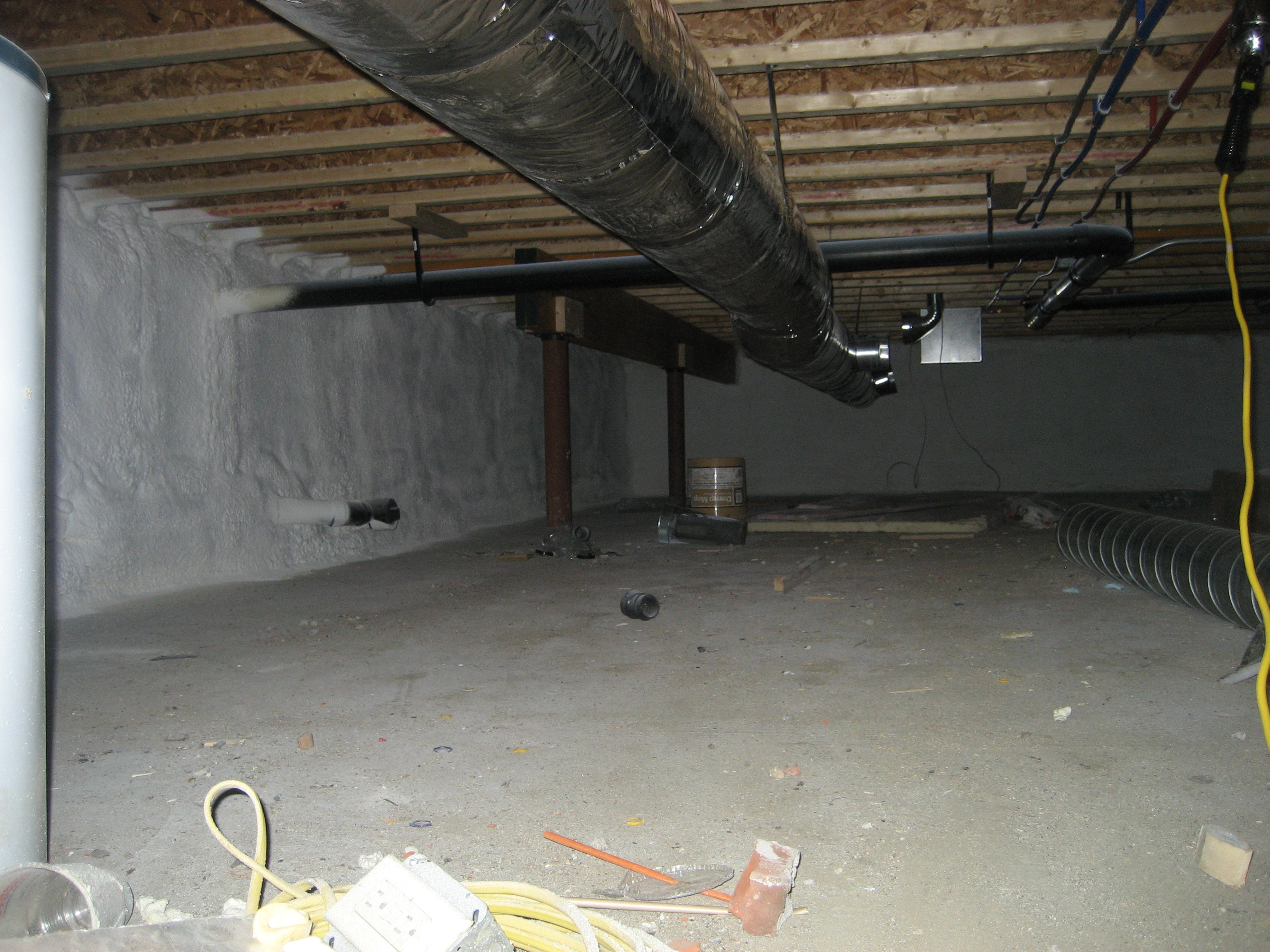
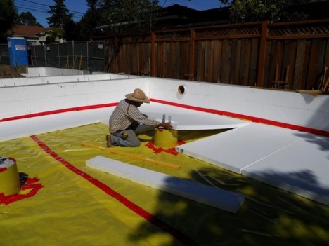
Rigid foam insulation and a thin slab were installed over the dirt and gravel of this sealed crawlspace
Image
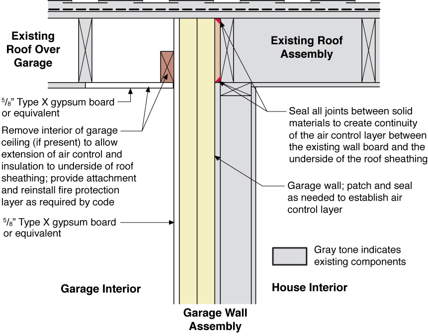
Rigid foam insulation is installed on the garage side of the shared garage wall and roof of an existing home
Image
Rigid insulation and water control layers are installed on the exterior of a flat foundation wall; spray foam insulates the rim joist
Image
Image
Image
Run-out ducts are installed over partition walls
Image
Image
Seal the drywall to top-plate seams and the lower edge of baffles to the top plate to prevent the air coming from soffit vents from flowing under baffles into insulation.
Image

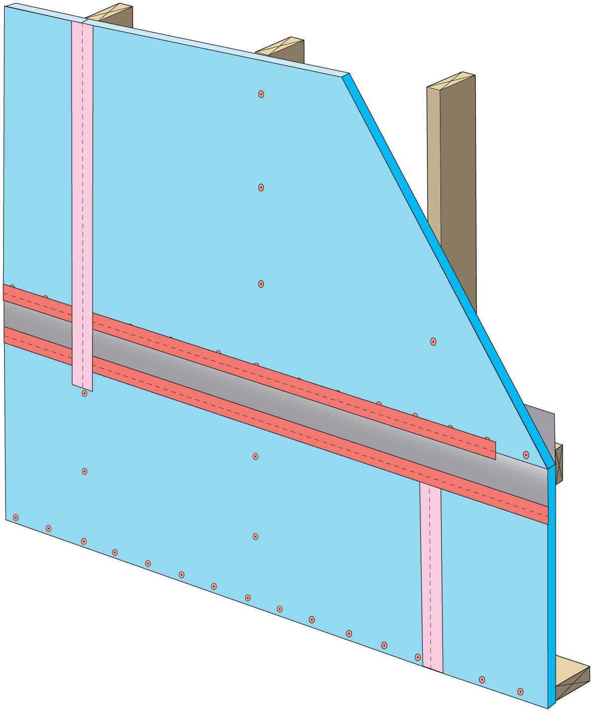
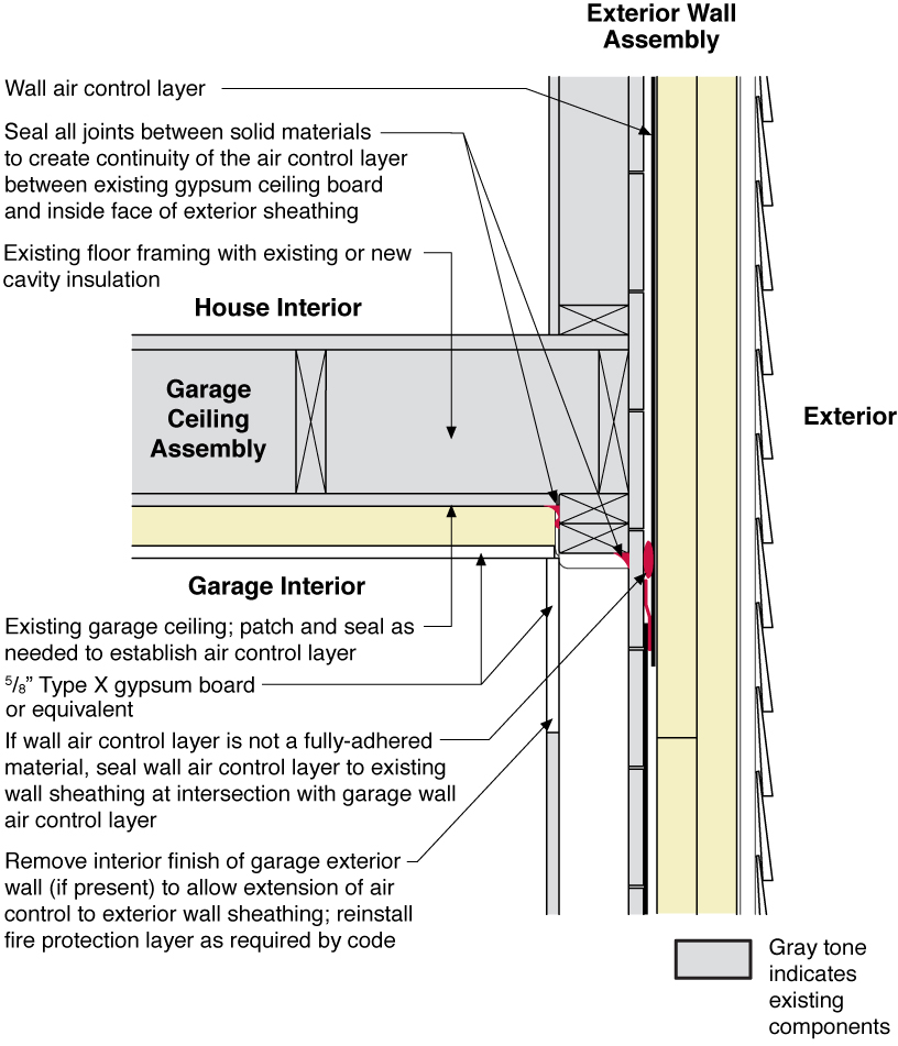
Side view showing air-sealing and rigid foam insulation is installed over existing wall and ceiling under a room above, then covered with new gypsum board.
Image
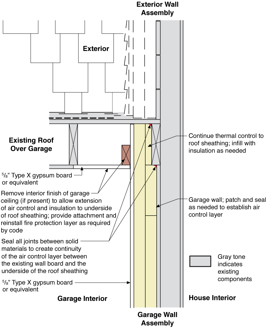
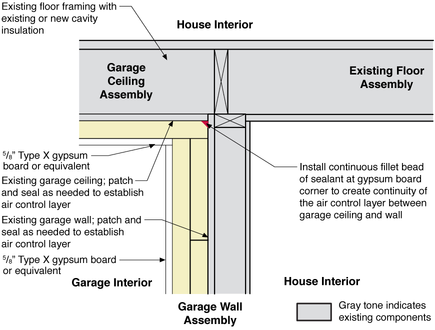
Side view showing how the existing garage wall and ceiling are air-sealed prior to installing rigid foam insulation on the garage side of the shared wall of an existing home.
Image
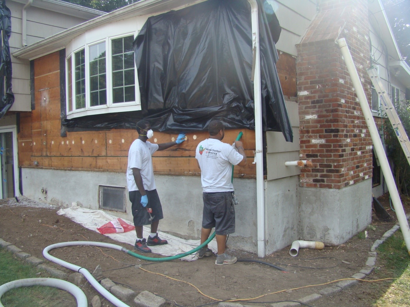
Siding has been removed so cellulose insulation can be dense-packed into the exterior walls of this home
Image
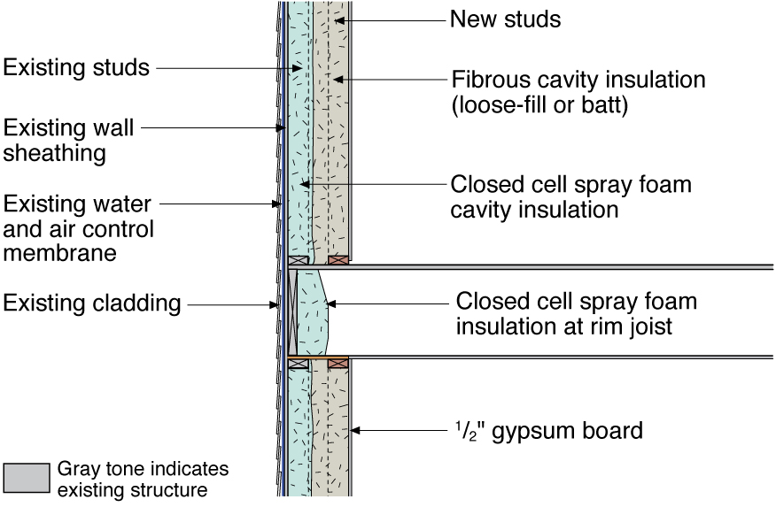
Single framed wall converted to double wall and insulated with closed-cell spray foam and loose-fill fibrous insulation
Image
Image

Sleepers (tapered wood furring strips) are installed over the existing board sheathing to slope the new sheathing toward the drain in this flat roof retrofit
Image
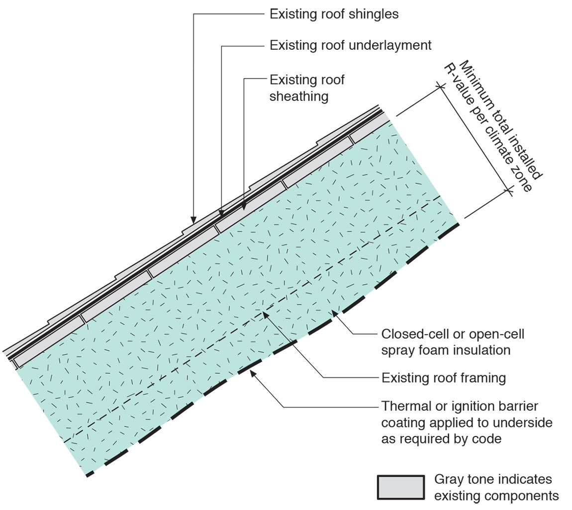
Sloped roof with cavity spray foam insulation sprayed on underside of roof deck and covered with sprayed-on thermal or ignition barrier coating.
Image
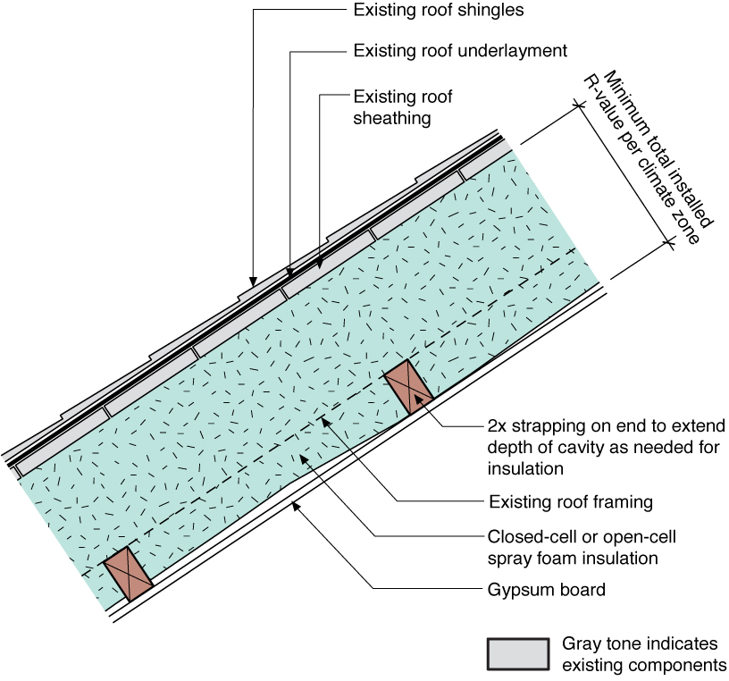
Sloped roof with cavity spray foam insulation, strapping, and gypsum board thermal barrier
Image
Some builders create pan joists by attaching a solid sheet good to the bottom of a floor joist to create a return air pathway
Image

Spray foam extends down the foundation wall to the slab, which has been retrofitted by adding dimple plastic drainage mat and rigid foam insulation.
Image
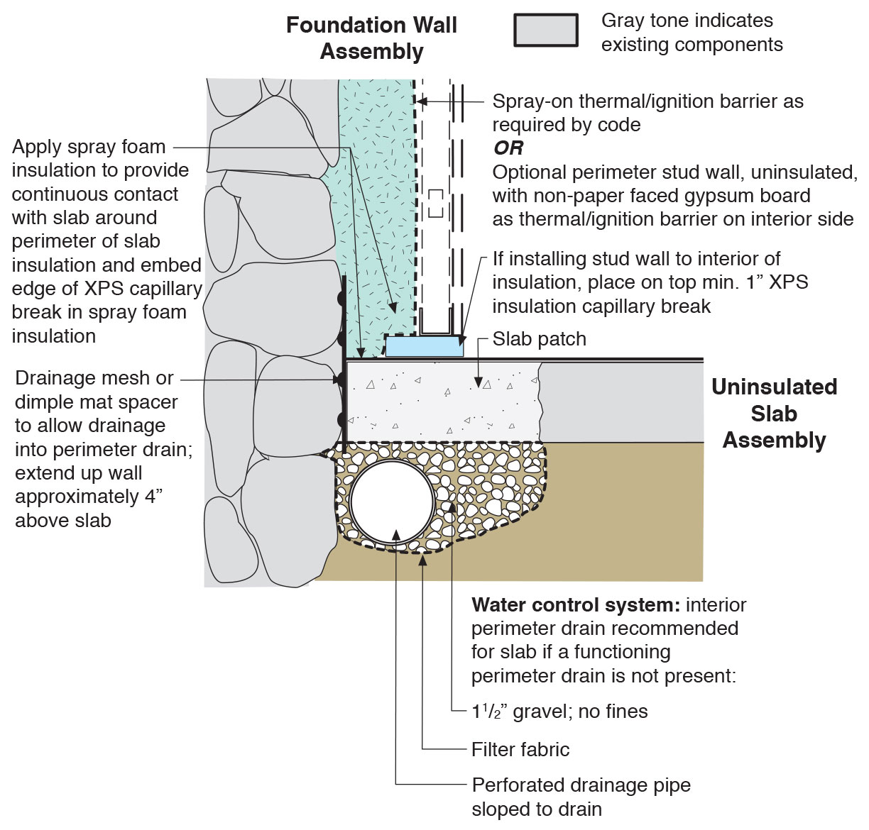
Spray foam extends down the inside of the foundation wall to the uninsulated slab; because the wall lacked exterior perimeter drainage, the slab was cut and an interior footing drain was installed.
Image

Spray foam insulation extends down the foundation wall to the slab, which has been retrofitted by cutting the slab to install drainage mat against the wall and a new perimeter footing drain, along with rigid foam plastic above the slab.
Image
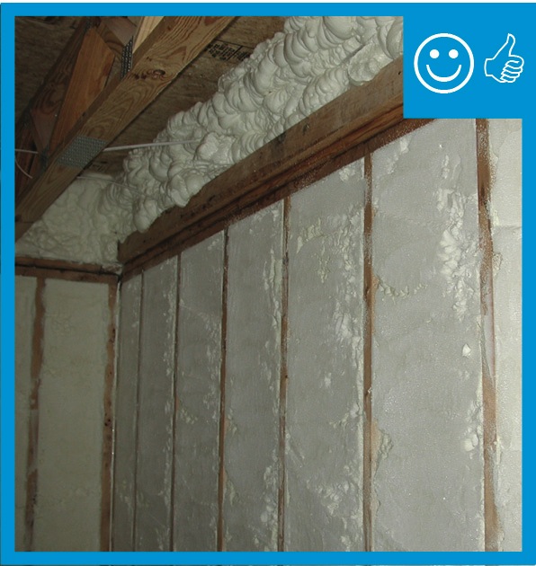
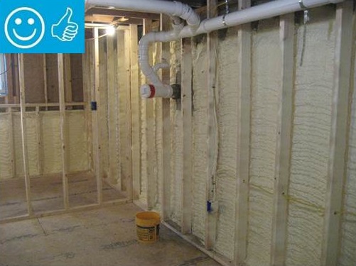
Spray foam insulation is installed in open wall cavities to air seal and insulate
Image
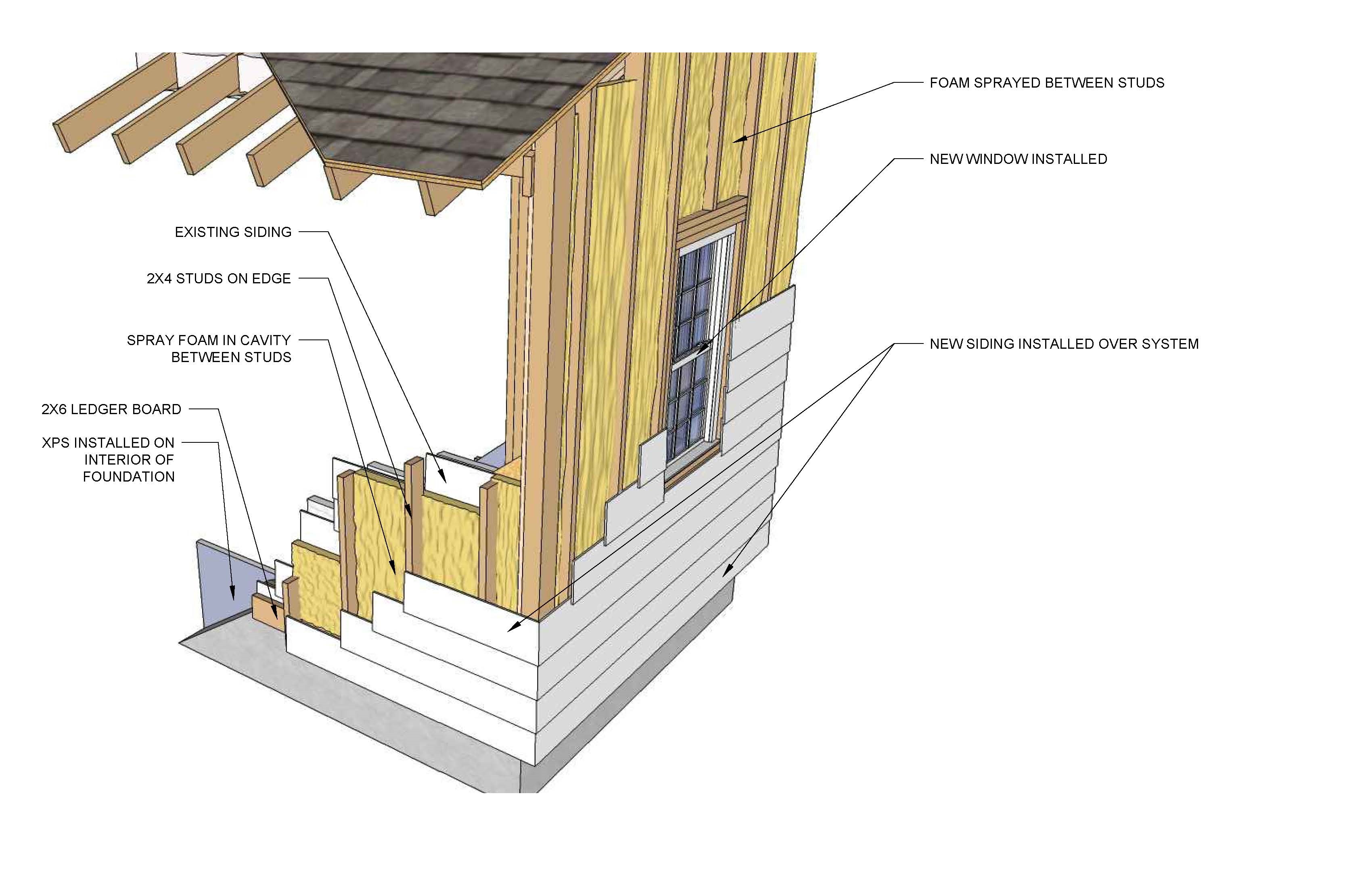
Spray foam is installed between new studs over the existing siding in this deep energy retrofit
Image
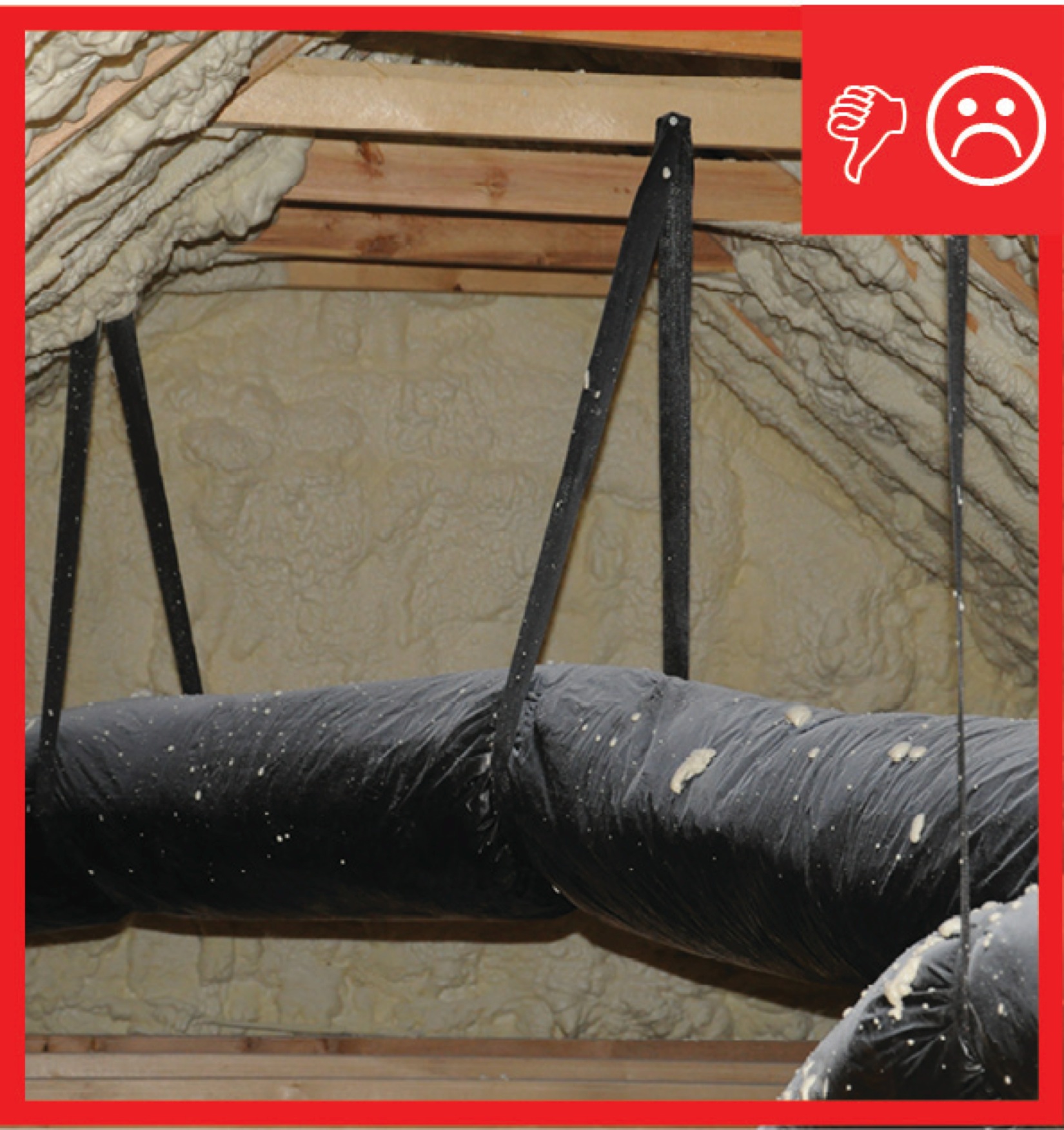
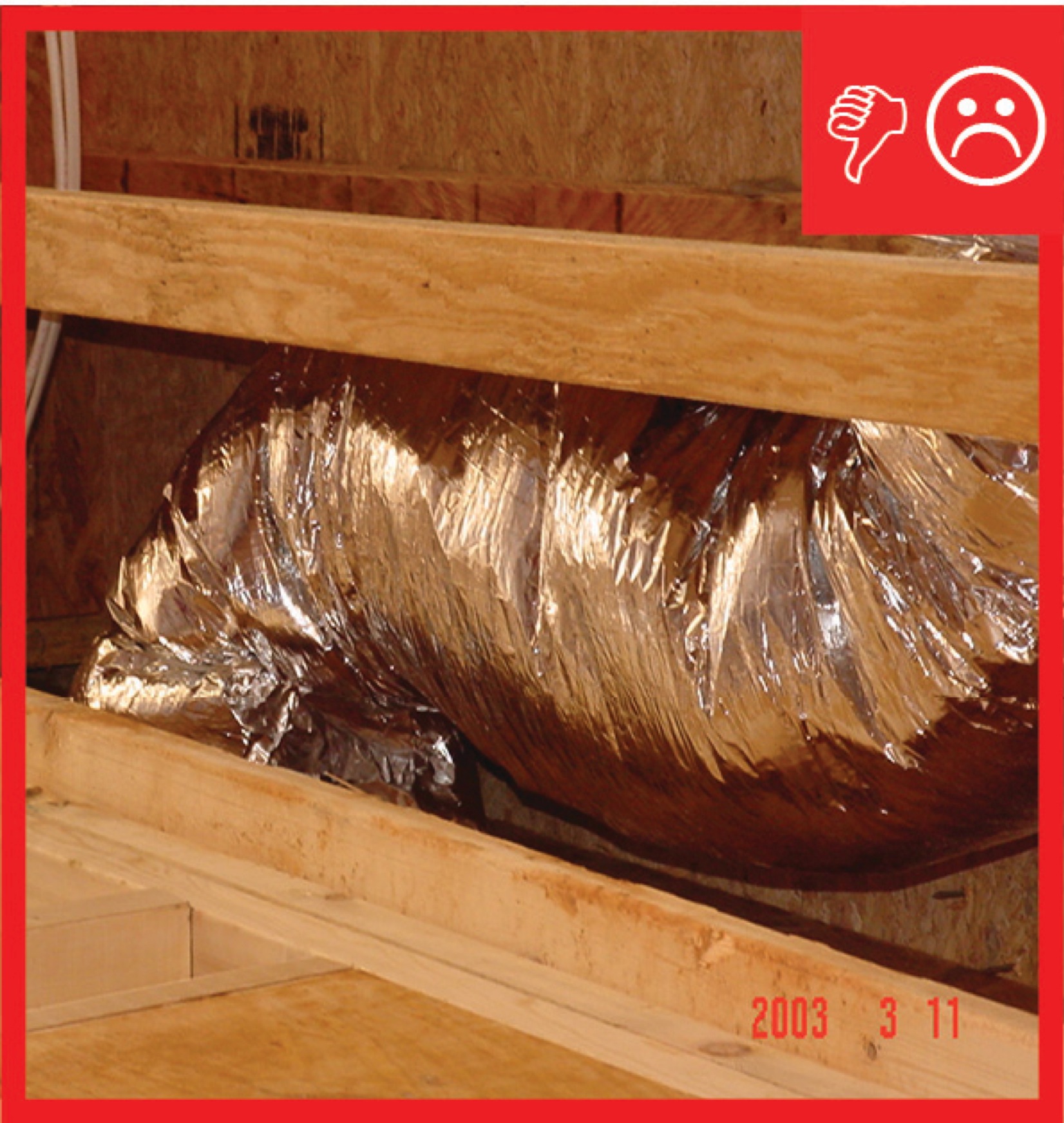
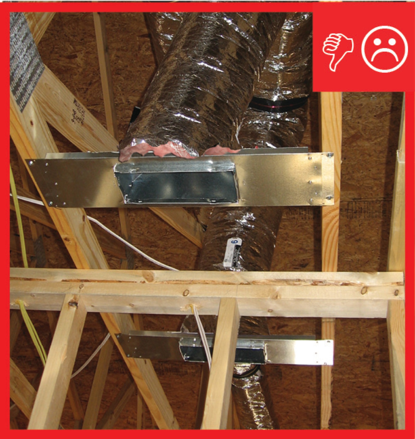
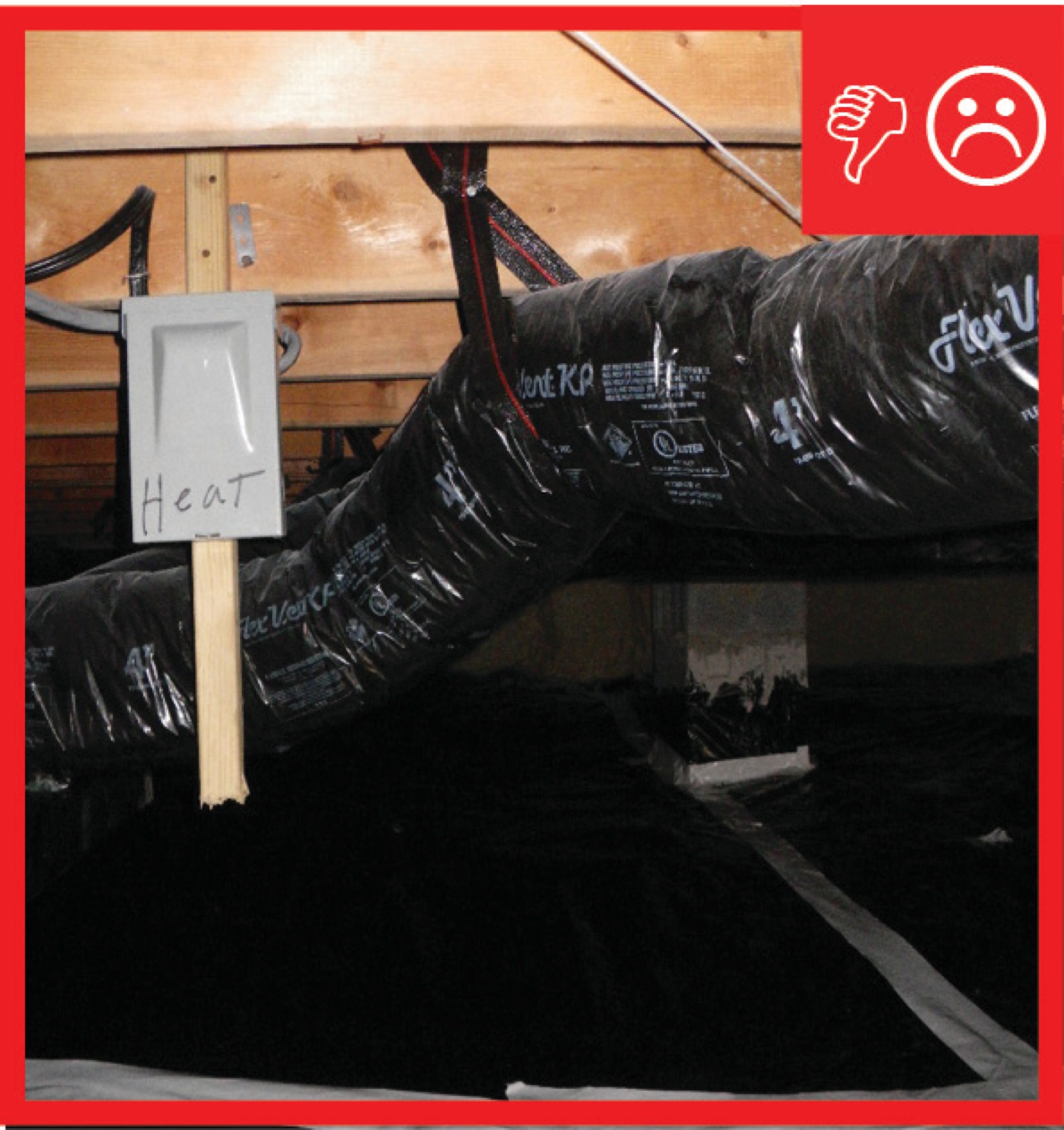
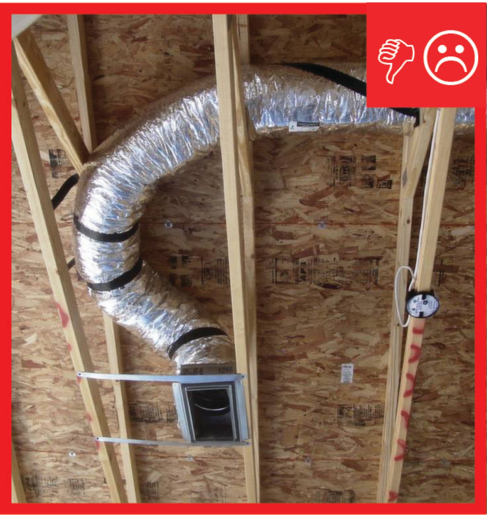
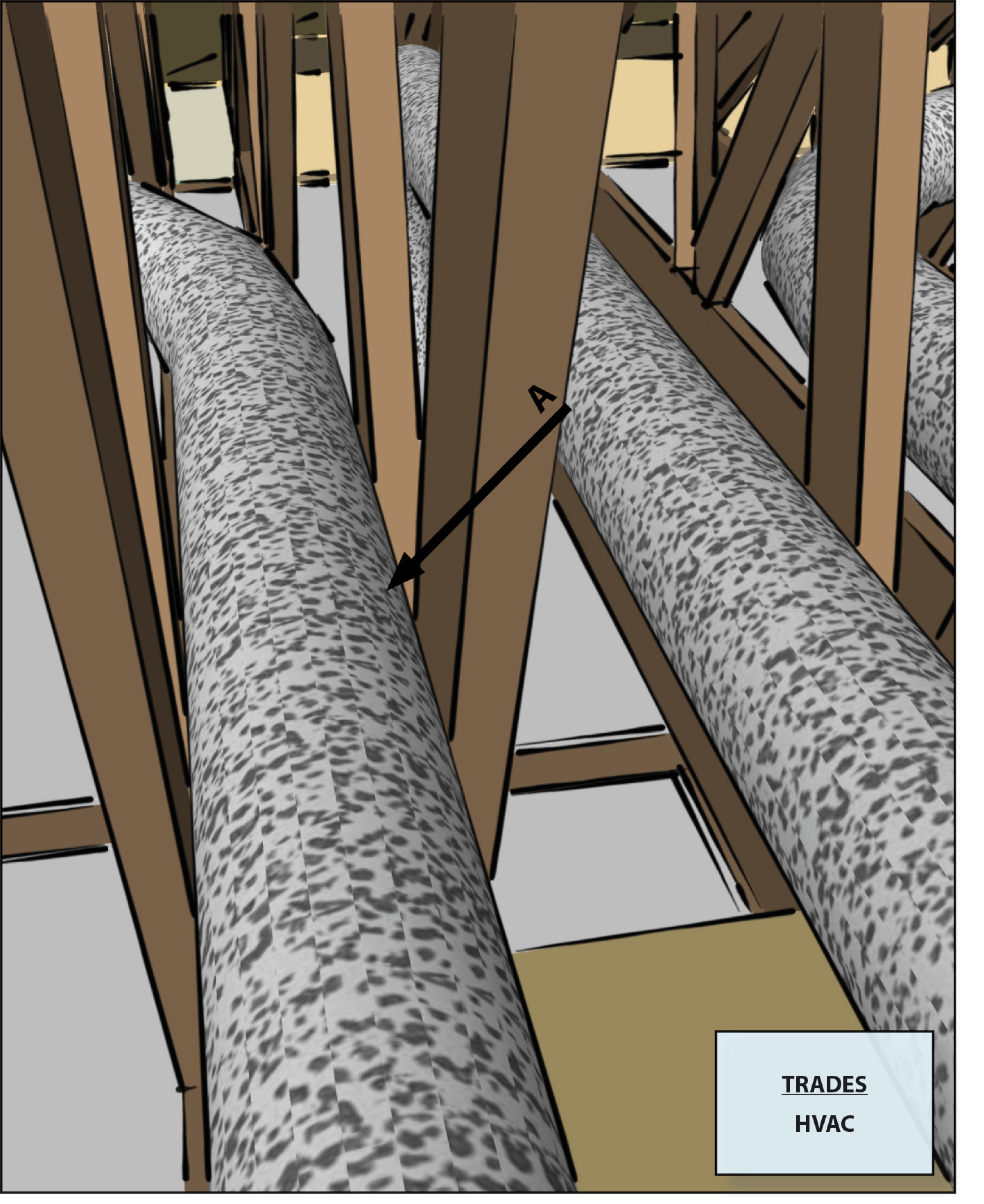
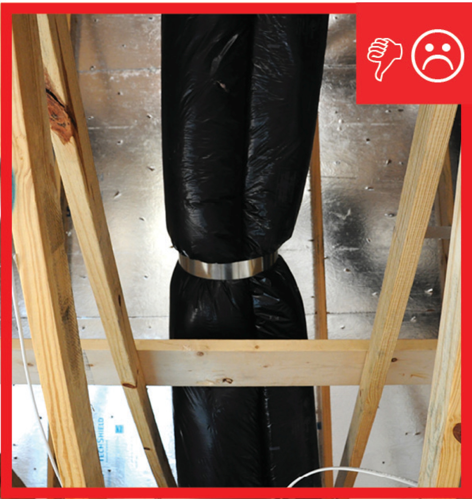
Straps are spaced too far apart causing the straps to compress the duct under its own weight
Image

Tape horizontal joint with minimum 3" wide tape placing tape offset high on the joint, adhearing to the upper sheet without wrinkles
Image
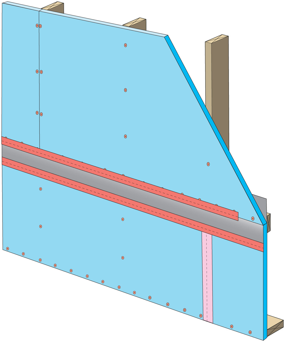
Tape the joint between the top insulation sheet and the Z-flashing with 2" wide tape to improve air tightness
Image
Image
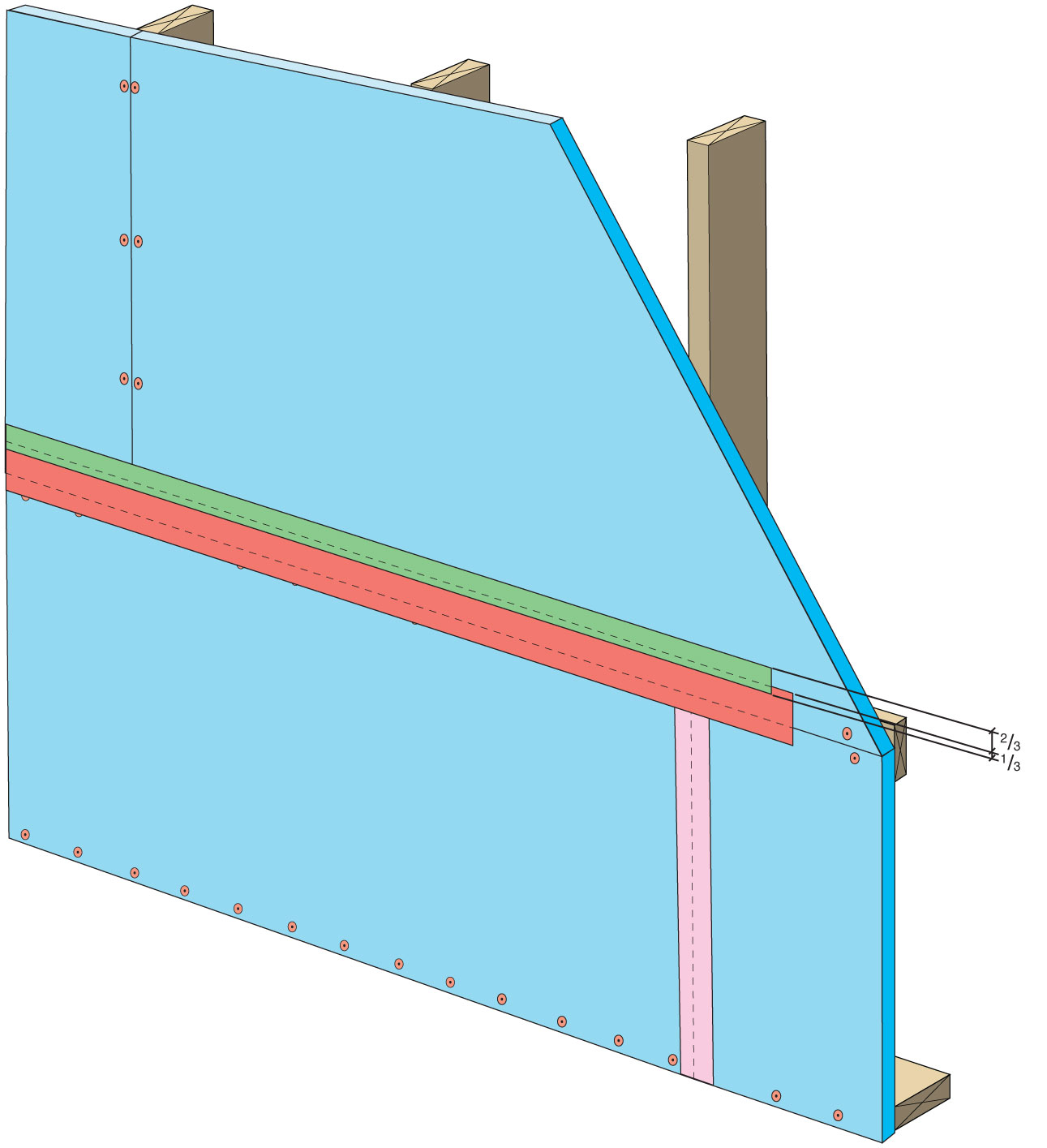
Terminate 4" tape with 2" wide tape placing tape offset high on the joint, 2/3 of the tape should be adhered to the sheet of insulation
Image
The attic kneewall and the open floor cavities under kneewall are both sealed and insulated in one step with spray foam insulation
Image
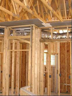
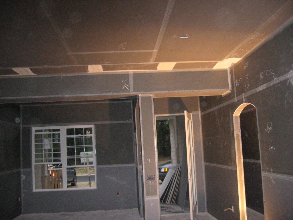
The drywall above the dropped ceiling duct chase extends beyond adjoining top plates for a continuous air barrier
Image
The furnace filter slot cover should fit tightly to minimize air leakage but it should not be taped or caulked to enable frequent filter replacements.
Image
The original corner seam is air-sealed with caulk, then rigid foam is installed on the existing garage ceiling and walls, and finally covered with drywall.
Image
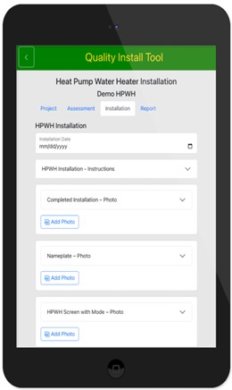
The PNNL Quality Install Tool simplifies and standardizes the documentation of HVAC installations and efficiency upgrades through photo-based prompts
Image
Image
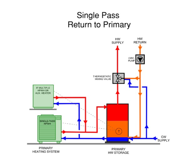
This central heat pump water heating system with a hot water circulation loop that returns to the primary storage tank relies on a single pass heat pump to provide both primary DHW heating and hot water circulation temperature maintenance
Image
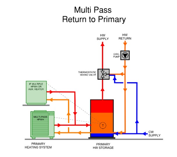
This central heat pump water heating system with a hot water circulation loop that returns to the primary storage tank relies on a multi pass heat pump to provide both primary DHW heating and hot water circulation temperature maintenance
Image

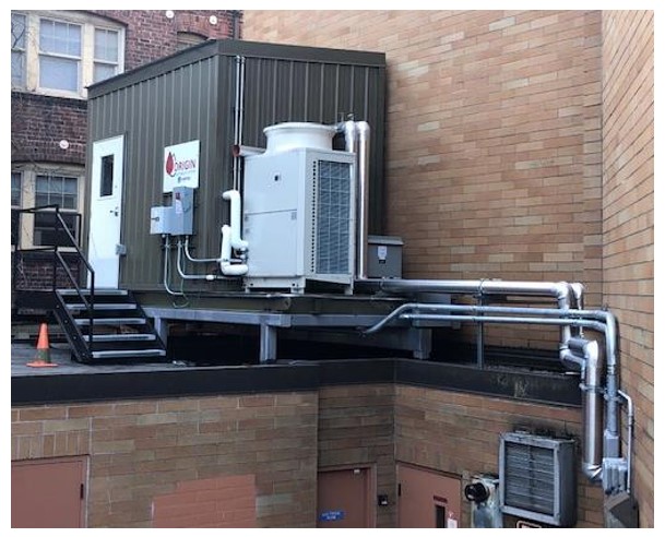
This fully packaged/skid-mounted central heat pump water heating system was shipped to the building on a truck and craned into location
Image
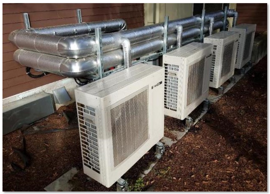
This fully specified central heat pump water heating system has four individual outdoor heat pump units plumbed in parallel to indoor storage tanks
Image
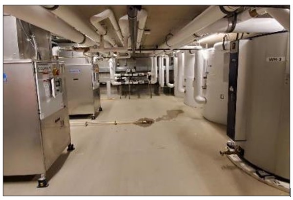
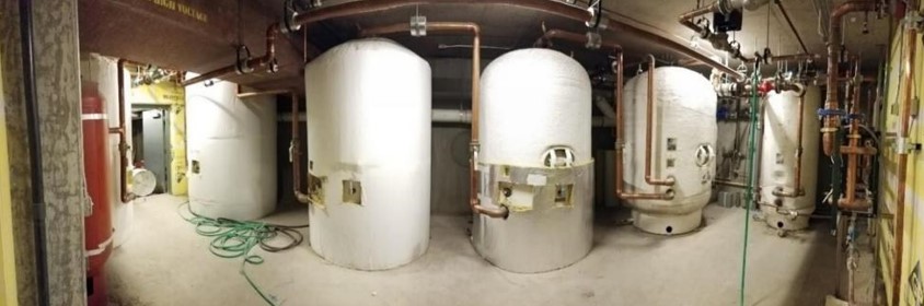
This mechanical room contains both the storage tanks (right) and heat pumps (left) of a central heat pump water heating system
Image
This new filter is inserted into furnace filter slot on the return side of the furnace with the arrow on the side of the filter frame pointing in the direction of airflow, which is toward the furnace.
Image
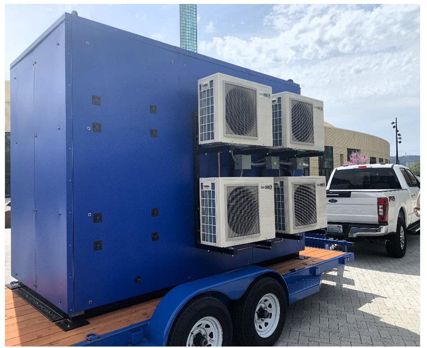
This packaged central heat pump water heating system has the heat pumps on the exterior of the blue enclosure, and the storage tanks, temperature maintenance equipment, mixing valve, and control modules on the inside
Image
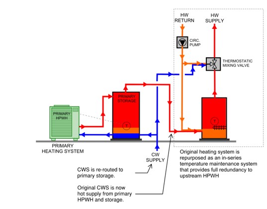
This retrofit central heat pump water heater system utilizes the existing water heater as a swing tank to provide temperature maintenance for the hot water circulation loop
Image
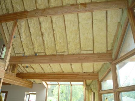
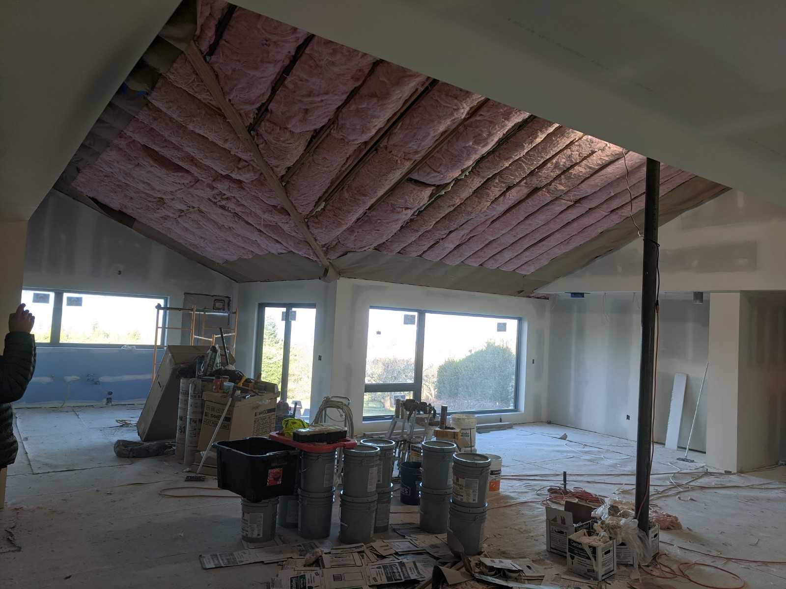
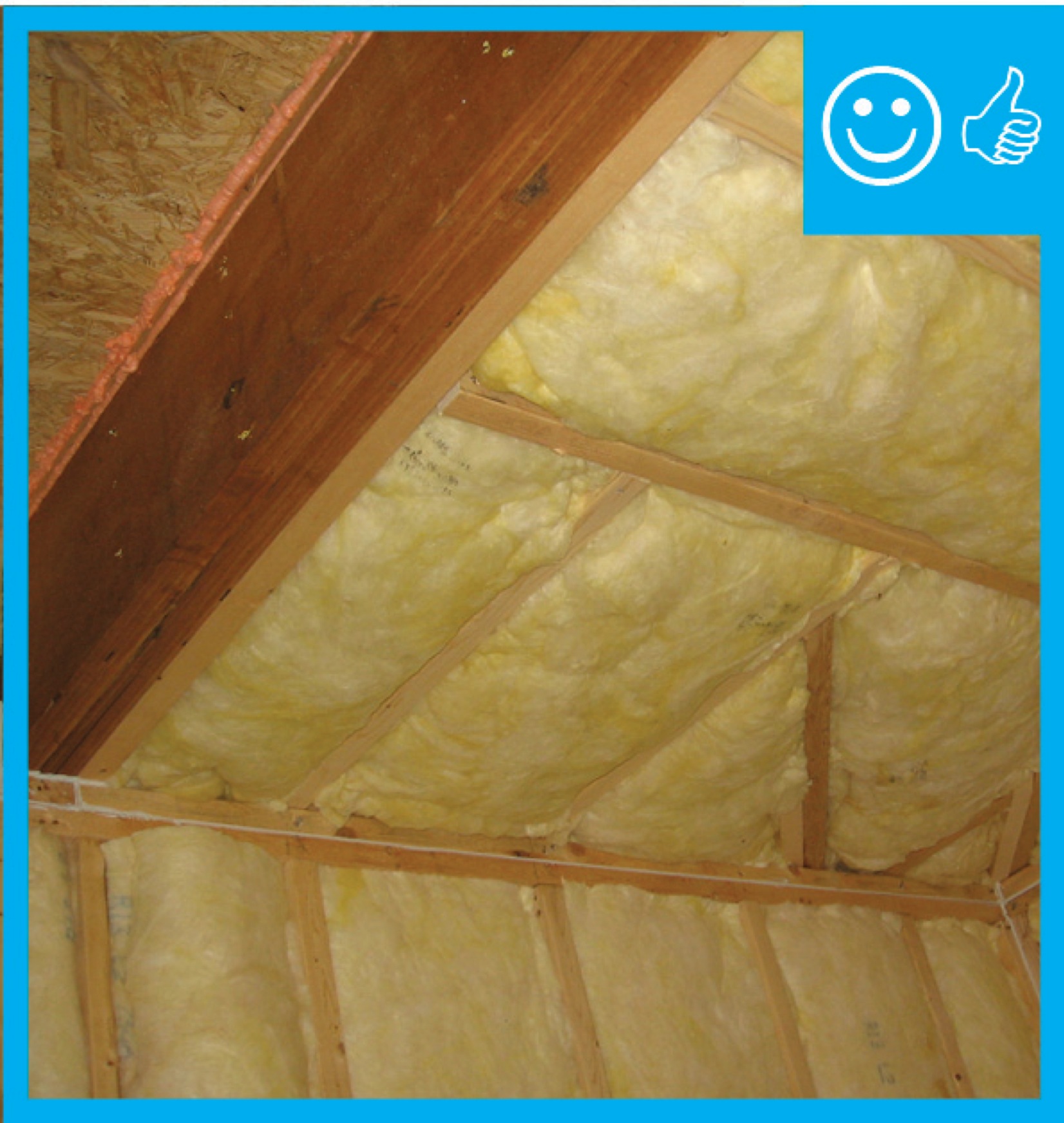
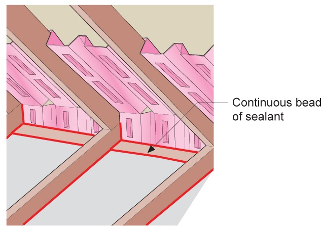
Three inches of closed-cell spray foam (R-19) and 7.5 inches (R-28) of open-cell spray foam was installed below the roof sheathing in this cathedral ceiling.
Image
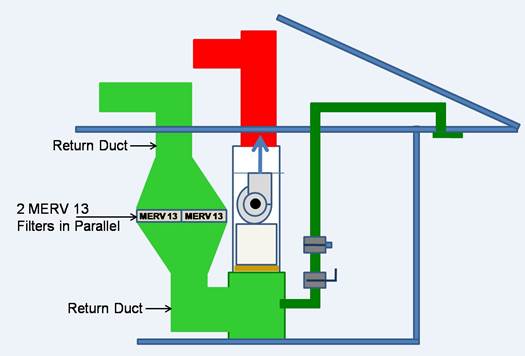
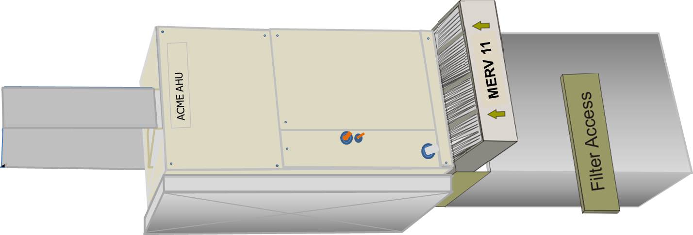
To increase surface area and reduce pressure drop for high MERV filters, the return duct can be constructed to permit the installation of two furnace filters side by side
Image
Image
Image
Image
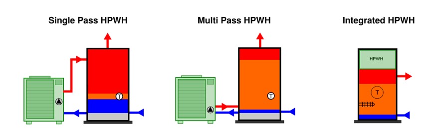
Types of heat pump water heaters commonly used in central heat pump water heating systems include single pass units, multi pass units, and integrated units
Image

Image

Unfaced fiberglass batt insulation is installed to completely fill the wall cavities and is sliced to fit around wiring, piping, and other obstructions in the wall cavities
Image
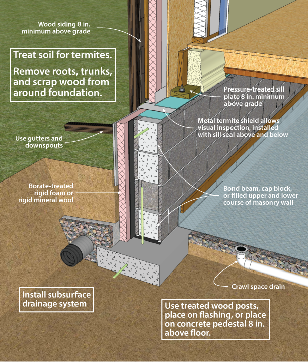
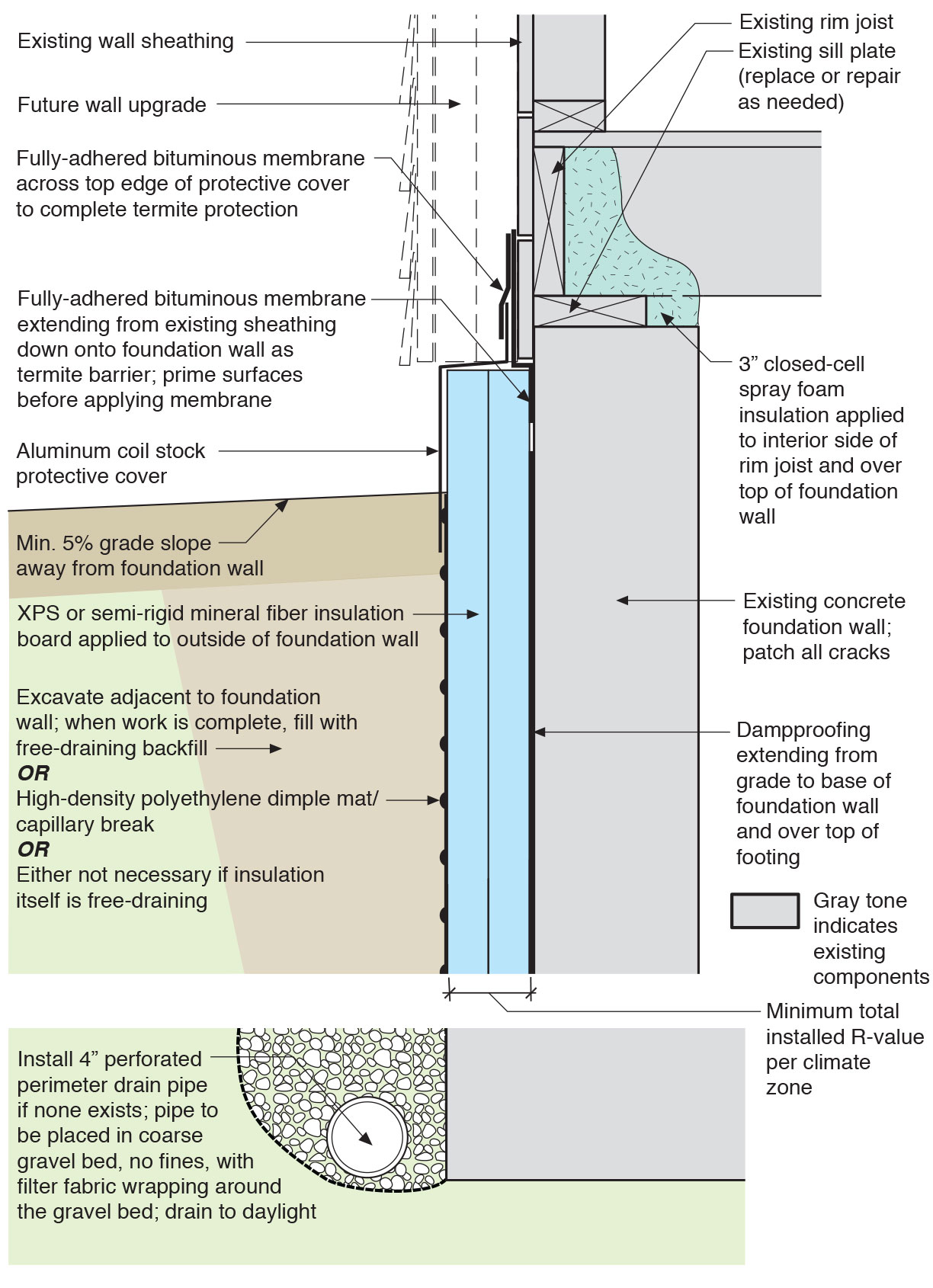
Unvented concrete masonry unit crawl space with exterior insulation - designed for termite resistance in moderately infested areas
Image
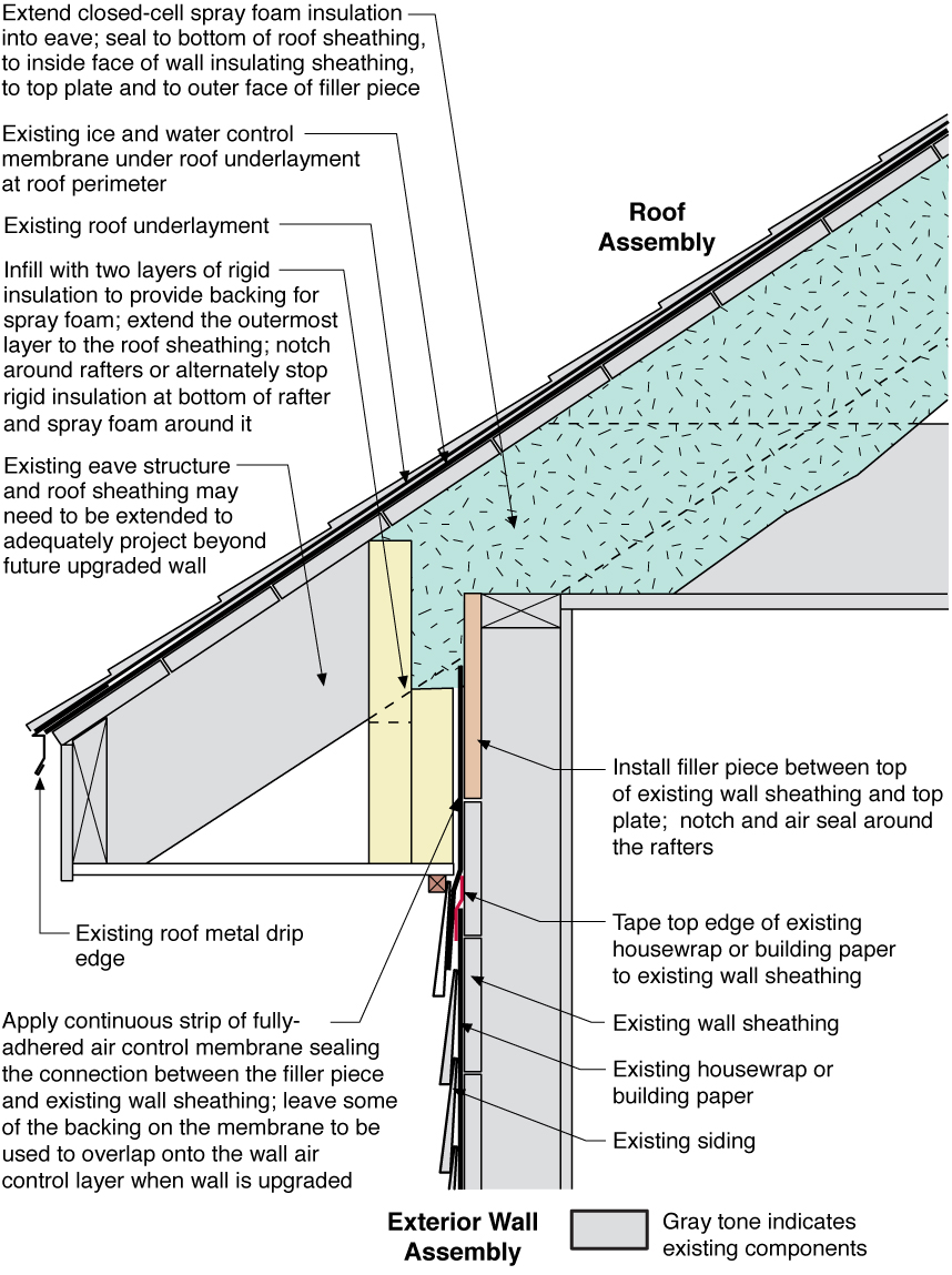
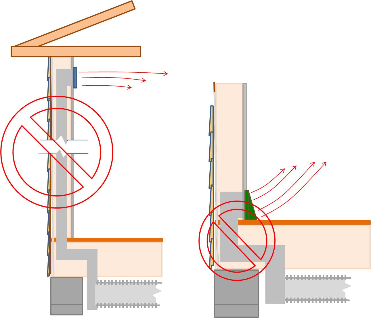
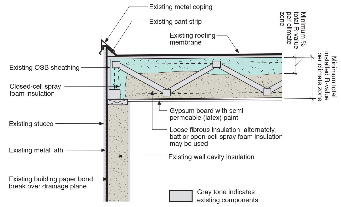
Unvented roof assembly at eave retrofitted with rigid foam, spray foam, and a fully adhered membrane seal at the top of wall-to-roof transition
Image
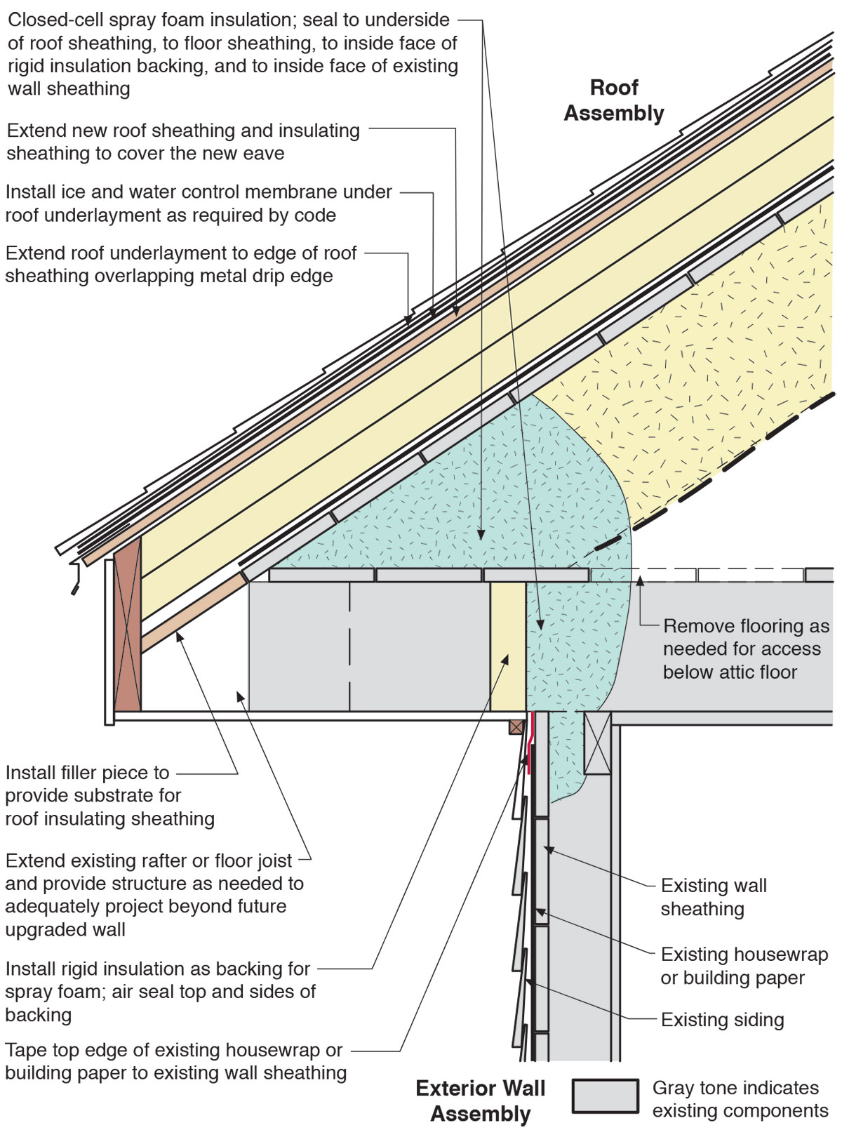
Unvented roof assembly at eave retrofitted with rigid foam, spray foam, and taped top edge of existing house wrap or building paper
Image
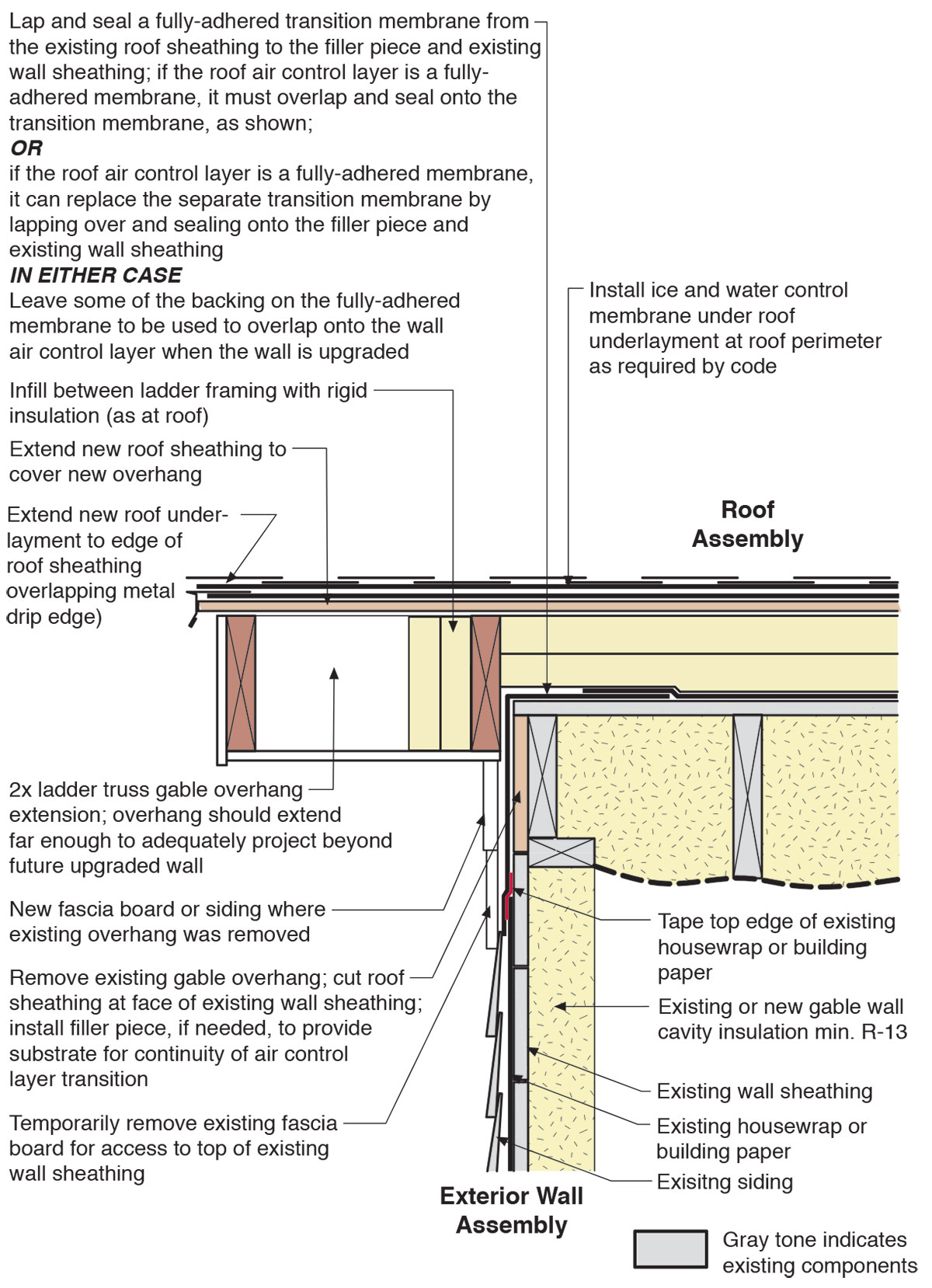
Unvented roof assembly at rake retrofitted with a filler piece and taped top edge of existing house wrap or building paper to seal the top of wall-to-roof transition
Image
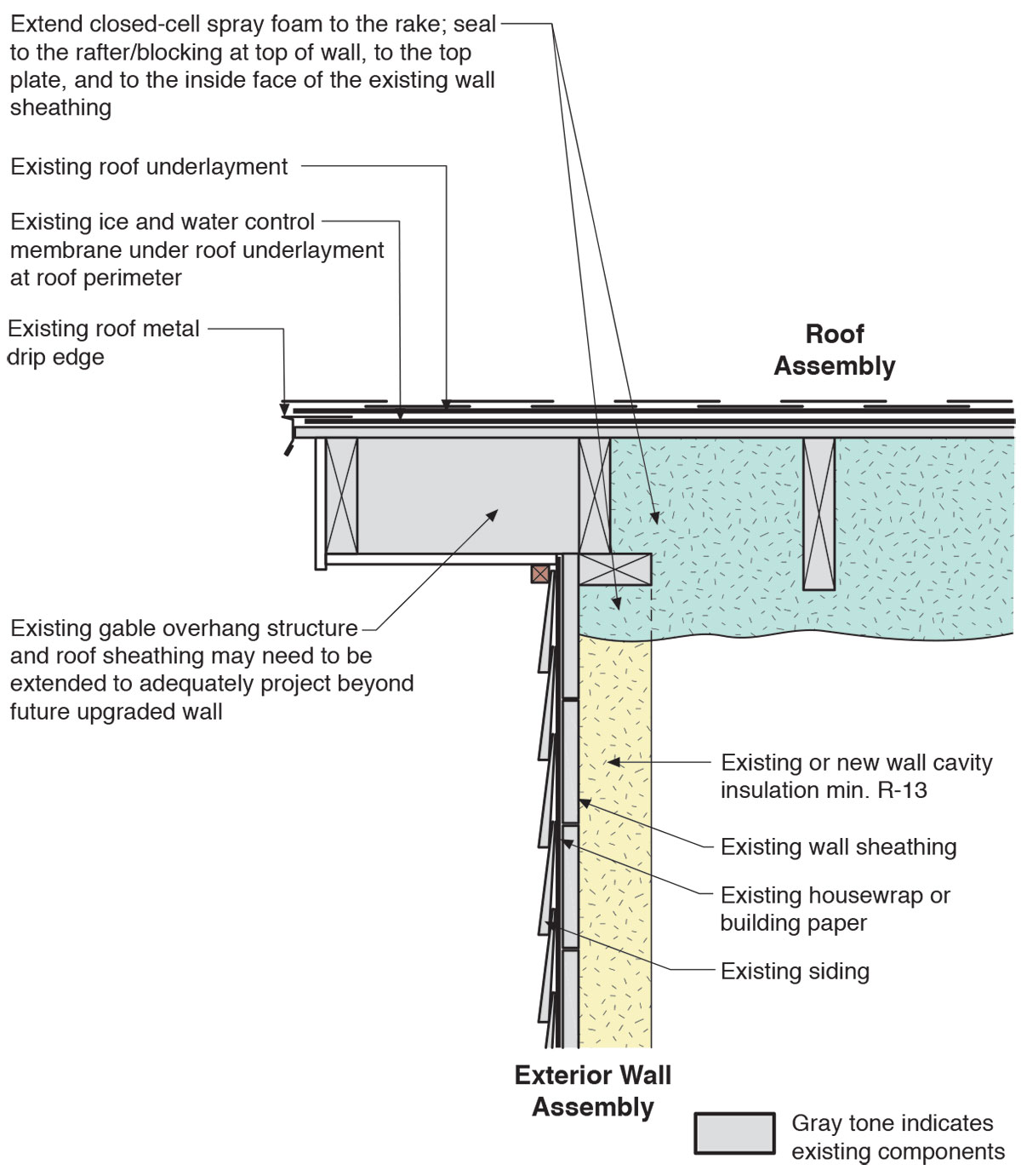
Unvented roof assembly at rake retrofitted with spray foam installed along the underside of the roof deck and extended to the rake edge to insulate and air seal the attic
Image