Showing results 451 - 500 of 578
Image
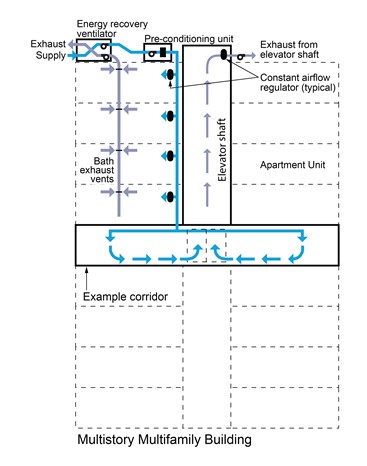
This central ventilation system uses an energy recovery ventilator, pre-conditioning unit, and elevator shaft exhaust fan to supply air to dwelling units and corridors and to exhaust air from units and the elevator shaft in a multifamily building
Image
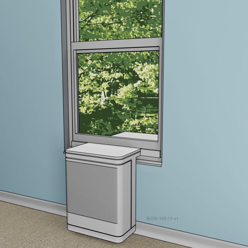
This depiction of a saddle installed window heat pump does not obstruct window use and provides fairly quiet 120 Volt operation
Image

This dropped soffit runs the length of the house providing a convenient place to locate one trunk duct with several very short side ducts that supply heat and cooling to most rooms of the house.
Image
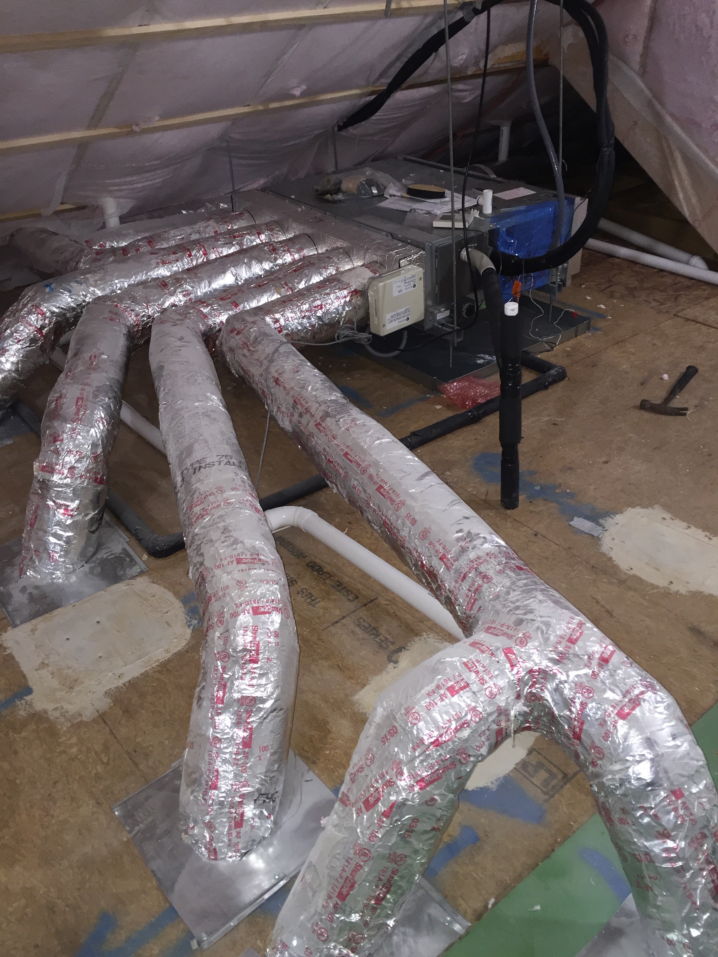
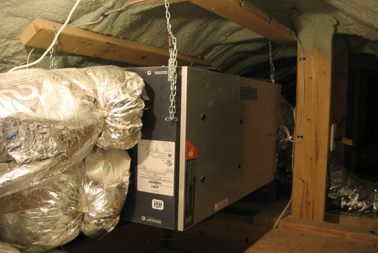
This ducted mini-split heat pump was installed in the unvented, conditioned attic and ducted with short duct runs to several nearby rooms.
Image
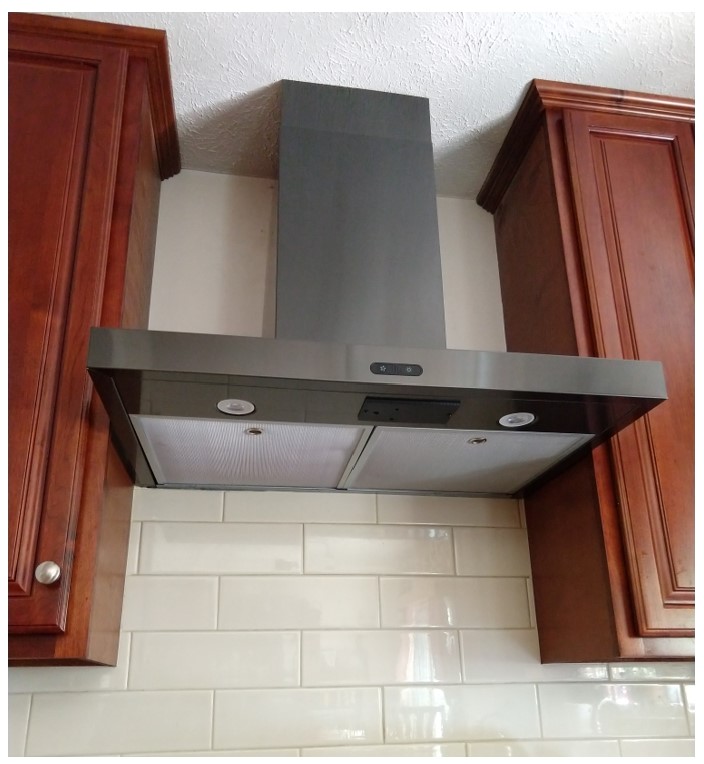
This ducted, wall-mounted range hood exhaust fan replaced a recirculating fan that did not adequately remove kitchen contaminants.
Image
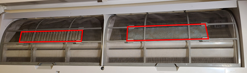
This ductless wall-hung indoor unit has supplemental air filters (outlined in red), which only filter a portion of the airflow; most of the air bypasses the supplementary filters and only passes through the standard mesh filters.
Image
This energy recovery ventilator (ERV) provides balanced ventilation to a dwelling unit in a multifamily building
Image
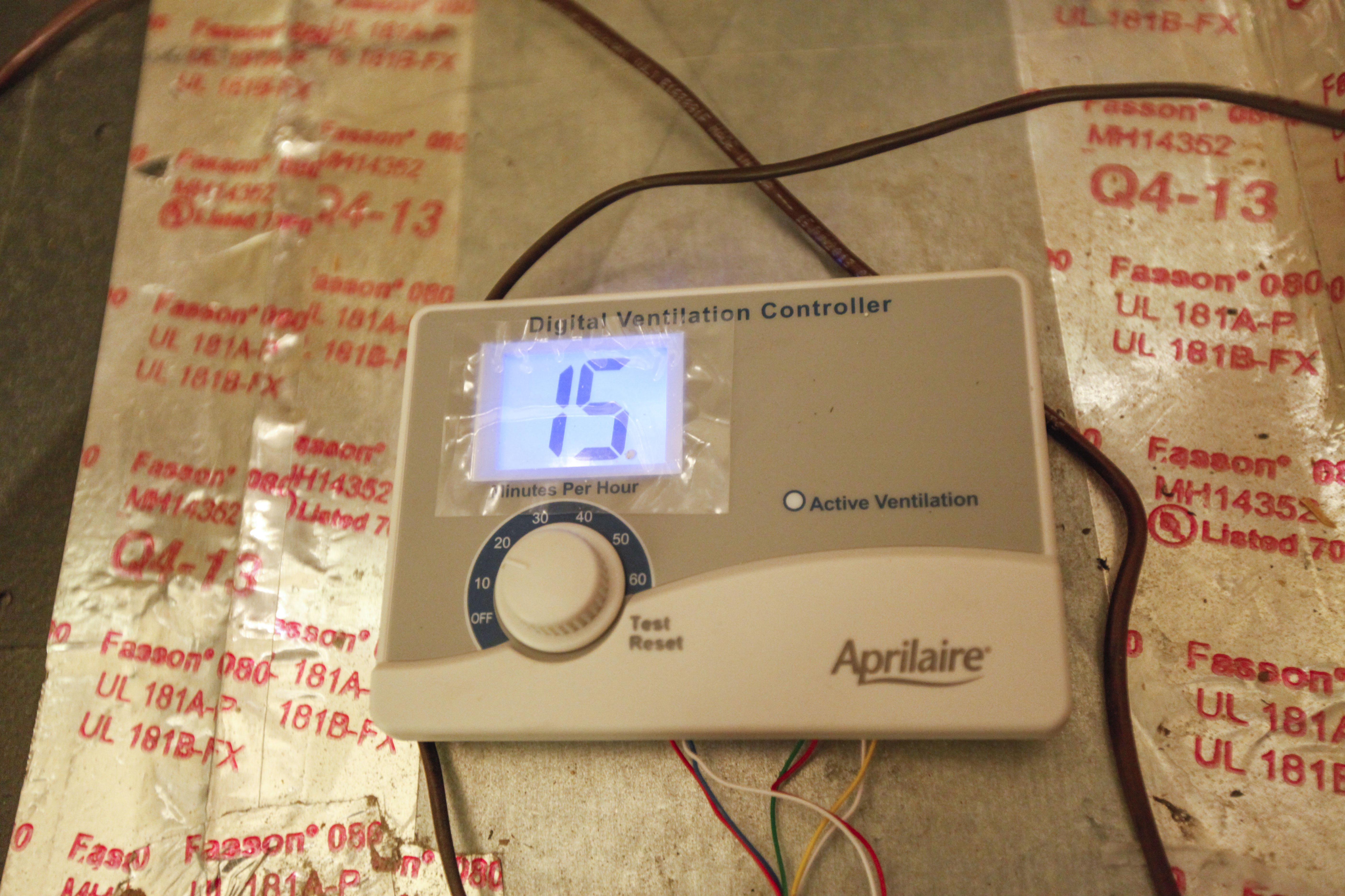
This home’s balanced fresh air system includes a filtered fresh air intake that is wired to the central HVAC system with timer controls while exhaust fans in the kitchen, bathrooms, and laundry room pull stale and moist air from the home.
Image
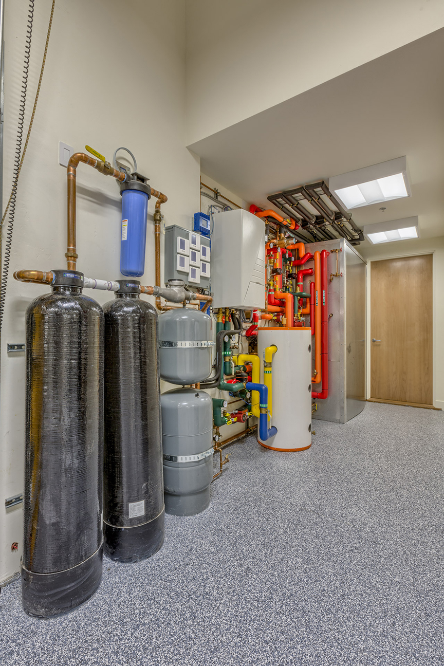
This home’s domestic hot water is provided by three systems: solar water heating panels, a heat pump water heater, and an air-to-water heat pump, which also provides hot water to a fan coil.
Image
This home’s ultra-efficient ground-source heat pump provides hot water for space heating as well as domestic hot water for the 50-gallon storage tank.
Image
This HRV, installed in a conditioned attic, provides balanced ventilation to the whole home
Image
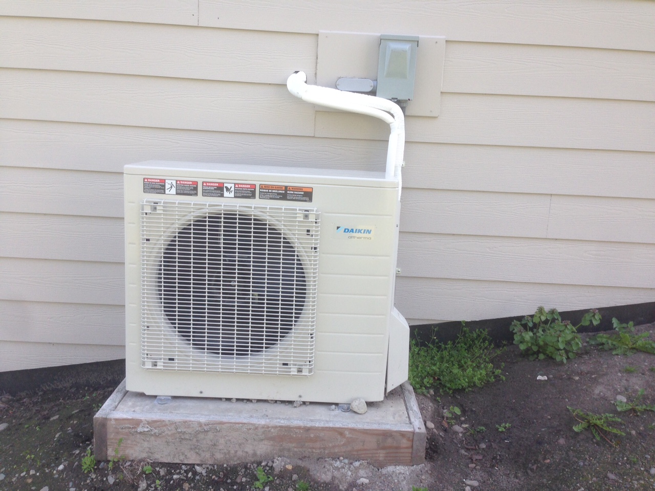
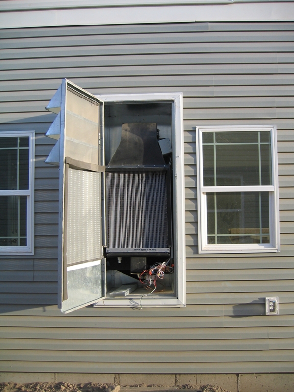
This is the compact outside unit for an ultra-efficient air-to-water heat pump (COP 4.1) that provides space heating and domestic hot water.
Image
This MSHP operates with 120 volts power, has an EER of 18 Btu/Wh, uses about 800 W at full output, and operates remotely with a smart home control system
Image
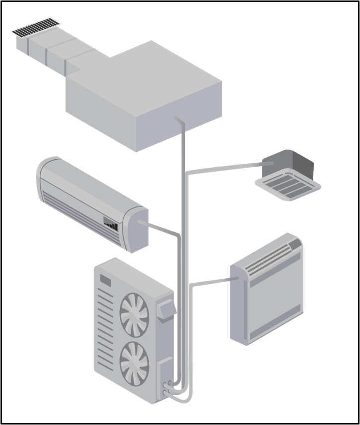
This multi-split heat pump system incorporates several indoor units connected to just one outdoor unit; the indoor units include a wall-mounted unit, floor-mounted, ceiling cassette, and mini-air handler.
Image
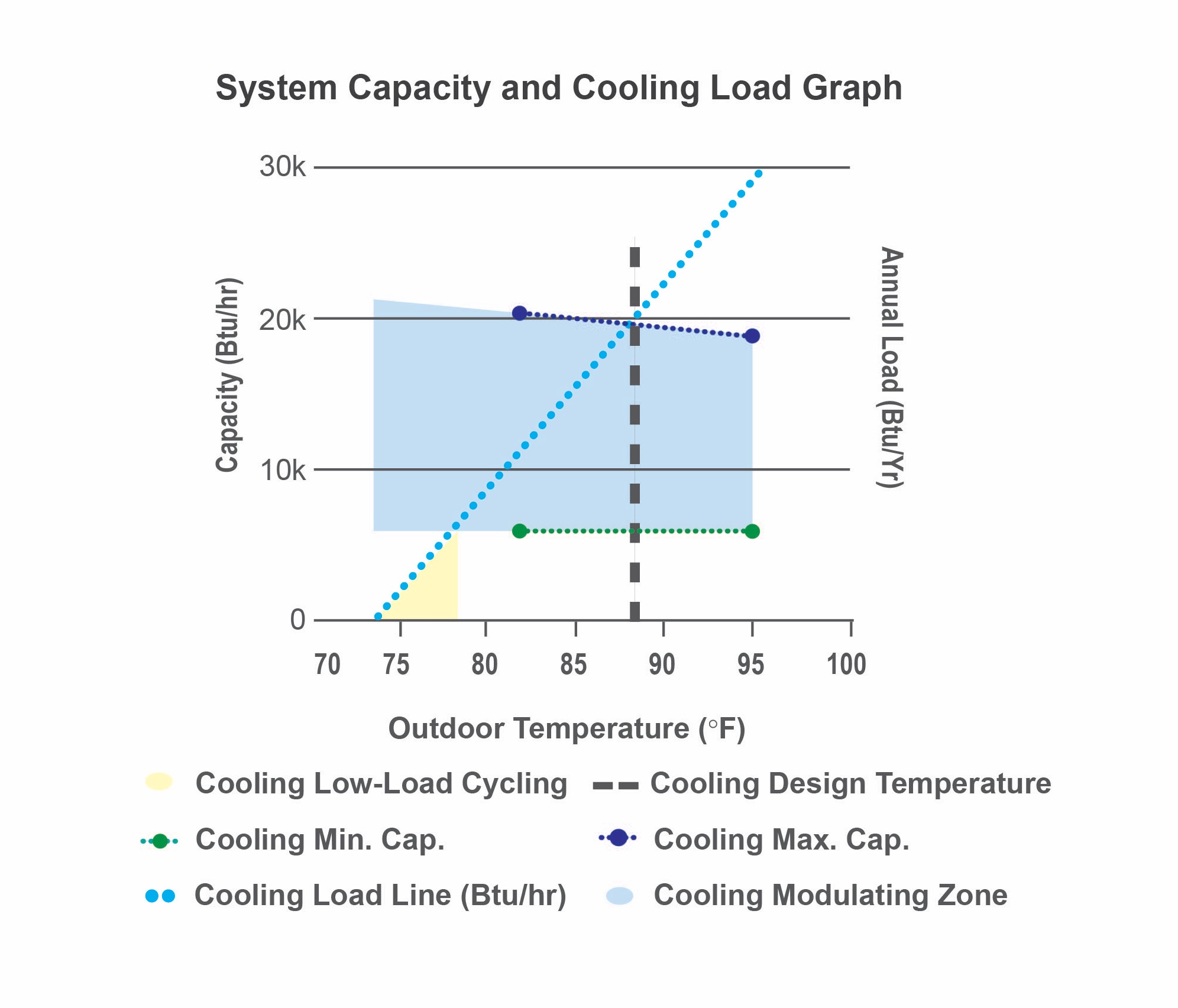
This plot shows a heat pump’s minimum and maximum cooling capacities overlaid with a home’s cooling load line, allowing a designer to assess how well-suited the equipment is for the specific home.
Image
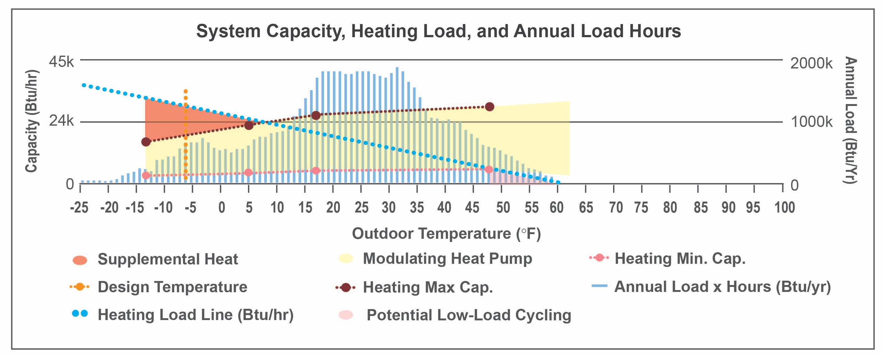
This plot shows a heat pump’s minimum and maximum heating capacities overlaid with a home’s heating load line as well as the annual heating load hours for the home, allowing a designer to assess how well-suited the equipment is for the specific home.
Image
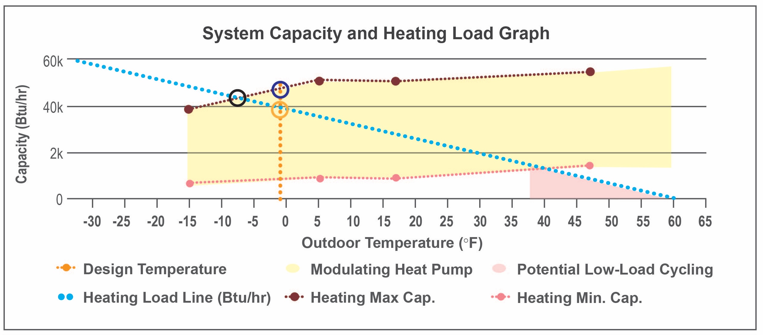
This plot shows a heat pump’s minimum and maximum heating capacities overlaid with a home’s heating load line, allowing a designer to assess how well-suited the equipment is for the specific home.
Image
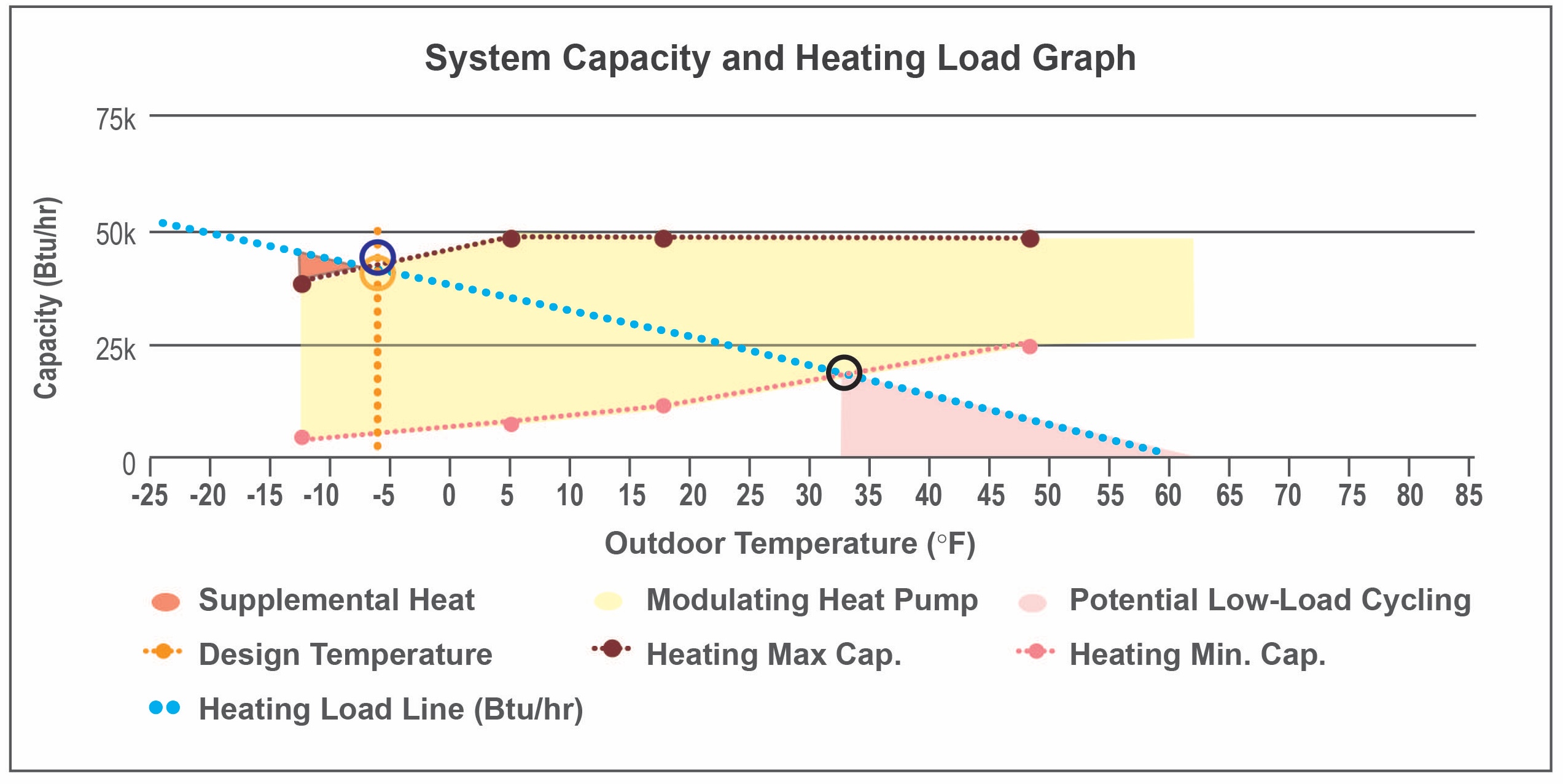
This plot shows a heat pump’s minimum and maximum heating capacities overlaid with a home’s heating load line, allowing a designer to assess how well-suited the equipment is for the specific home.
Image
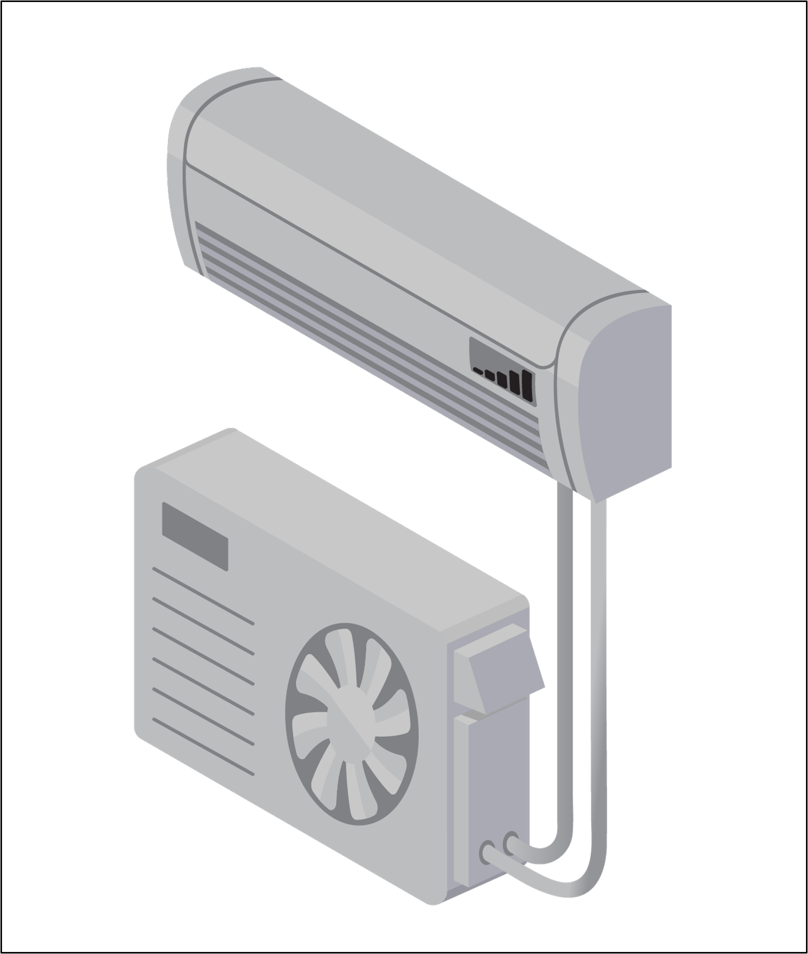
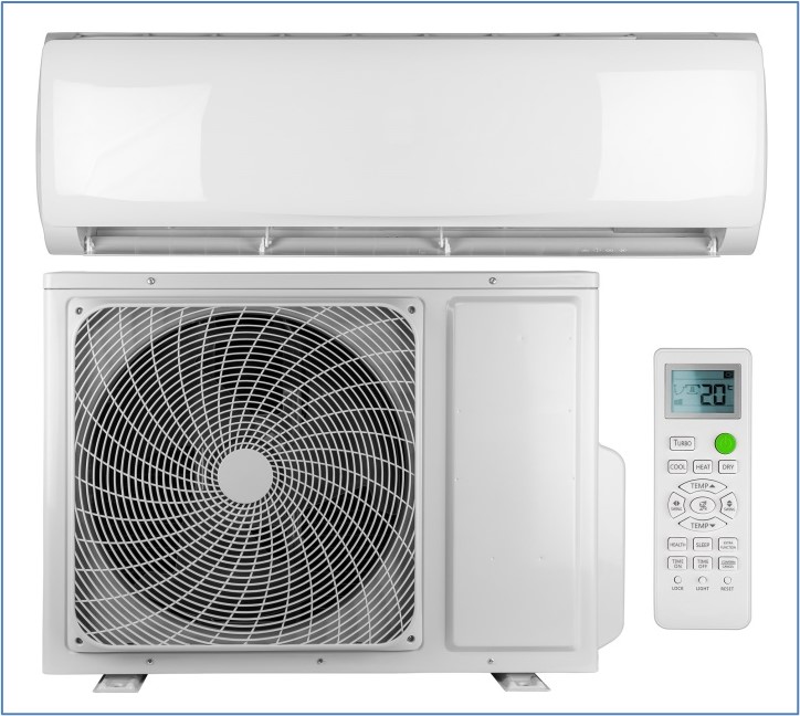
This single-zone mini-split ductless heat pump has only one indoor wall-mounted unit and one outdoor unit.
Image
This traditional centrally ducted heat pump heats and cools the entire home through a network of ducts.
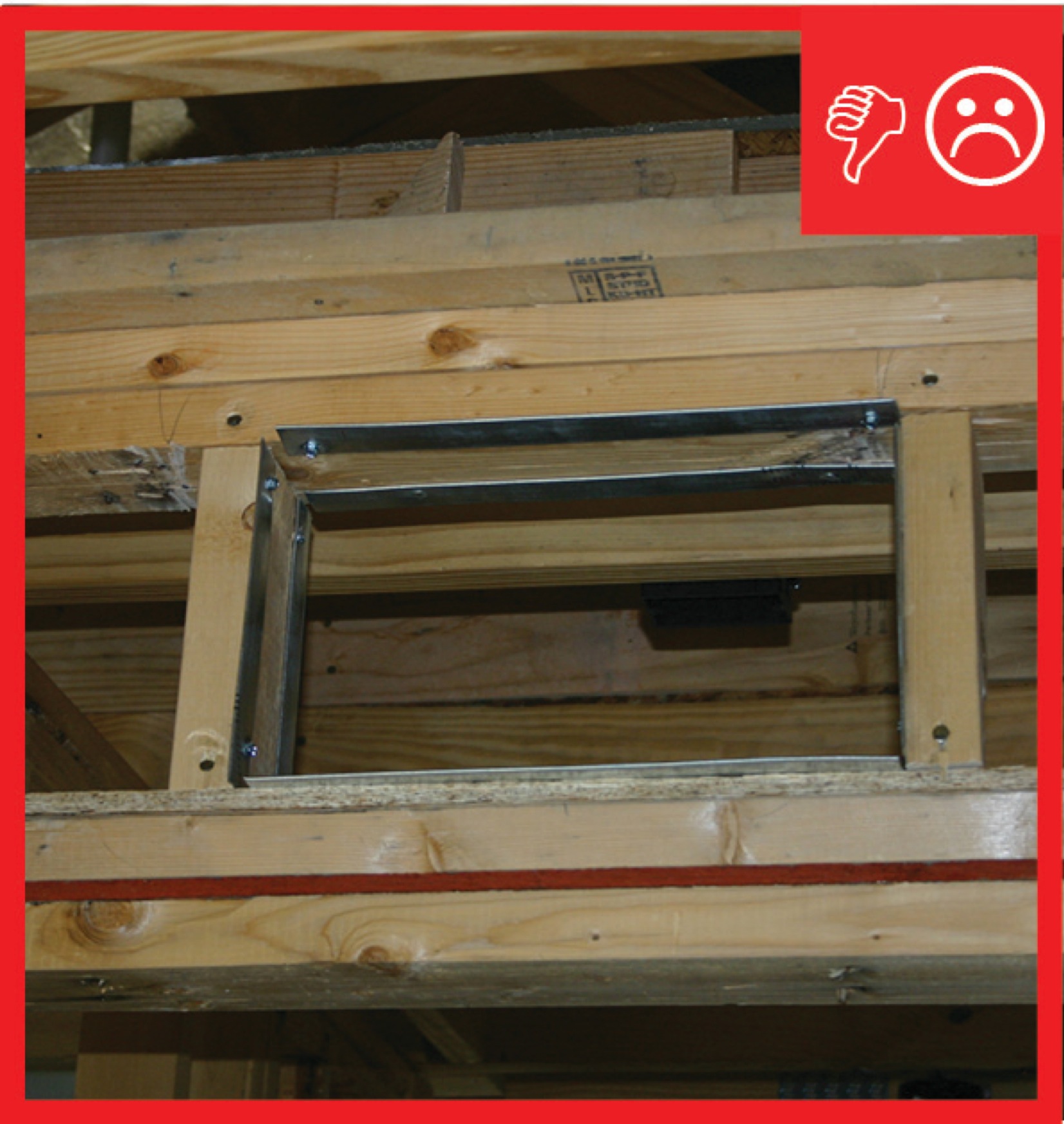
Image

This typical dropped ceiling hallway chase shows a complicated air sealing scheme where chase ceiling drywall meets sidewall top plates
Image
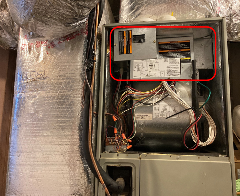
This upflow air handler for a traditional heat pump has an electric resistance auxiliary heating element located at the top of the unit (circled in red).
Image
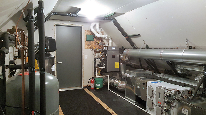
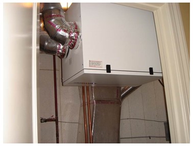
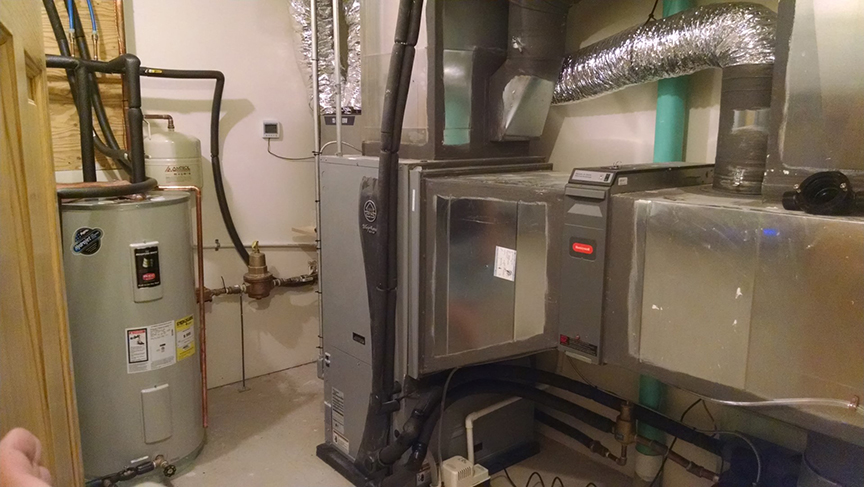
This utility room houses a high-efficiency gas boiler to provide hot water for the radiant floor heating system and faucets. It also has a central air source heat pump and an energy recovery ventilator.
Image
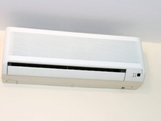
This wall-hung ductless indoor mini-split heat pump contains a fan, filter, and heating/cooling coil just like a traditional central air handler for a ducted heat pump system
Image
Image

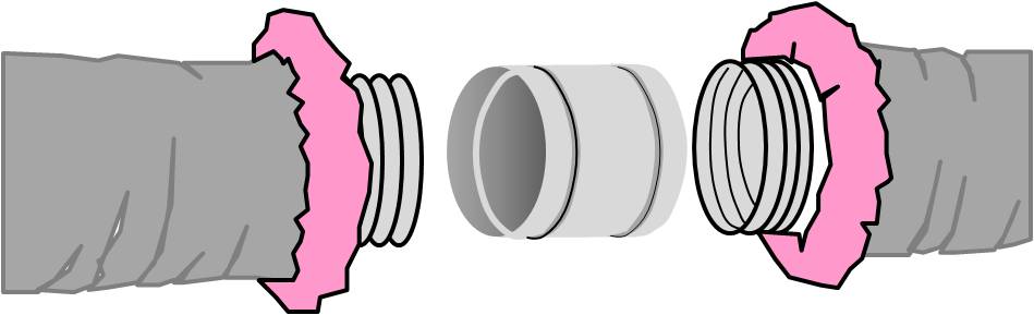
To attach the flex duct to a main trunk duct or any other connection, the flex duct is pulled over the connecting collar at least 2 inches past the raised bead, then the insulation is pulled back
Image
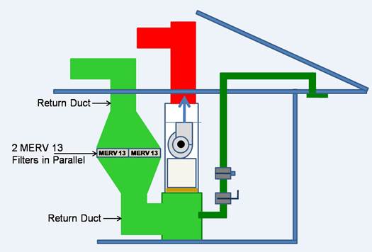
To increase surface area and reduce pressure drop for high MERV filters, the return duct can be constructed to permit the installation of two furnace filters side by side
Image
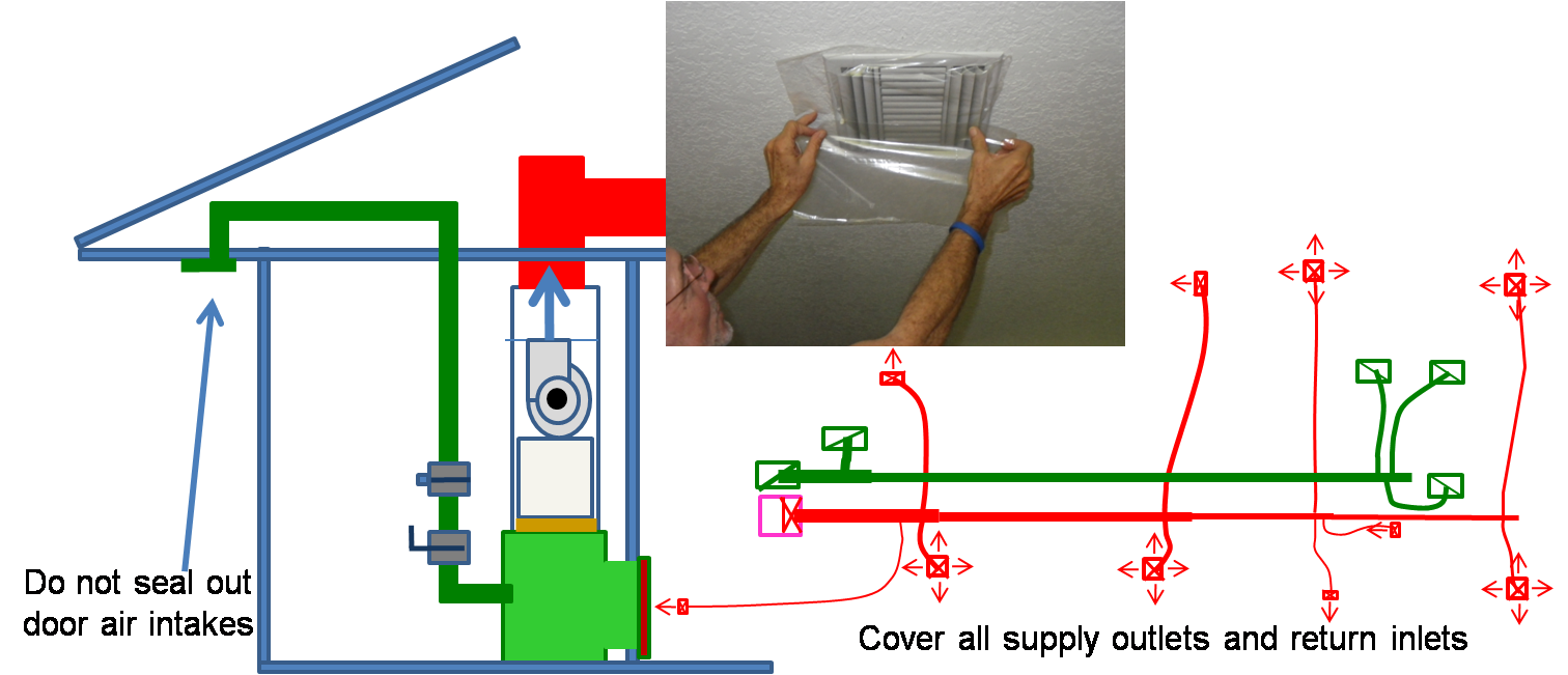
To prepare for a total duct test at final, cover all of the supply outlets and return inlets
Image
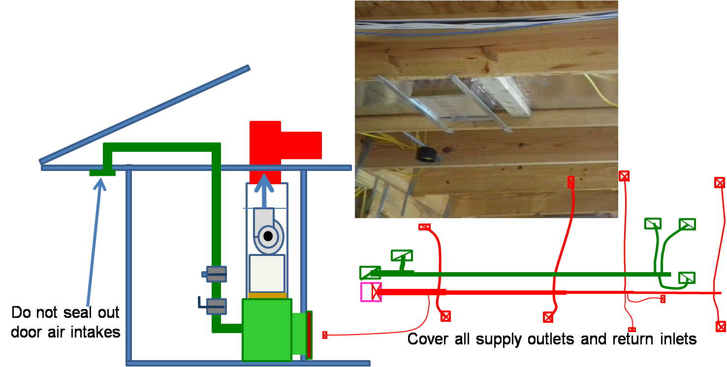
To prepare for a total duct test at rough-in, cover all of the supply outlets and return inlets
Image
Image
Image
Image
Transfer grills and jump ducts provide pathways for air to reach the centrally located HVAC return grille, even when bedroom doors are shut.
Image
Transom returns are installed over interior doors to provide a pathway for return air
Image
Image
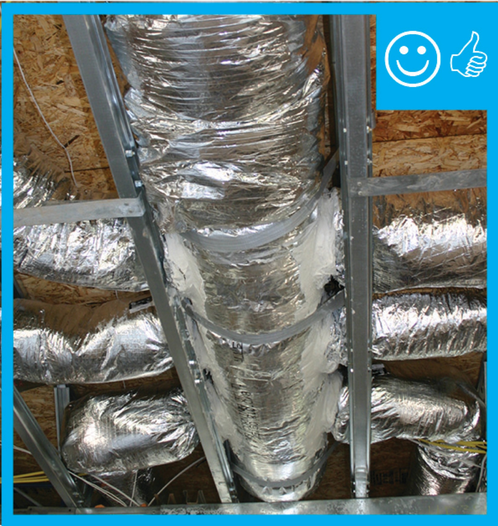
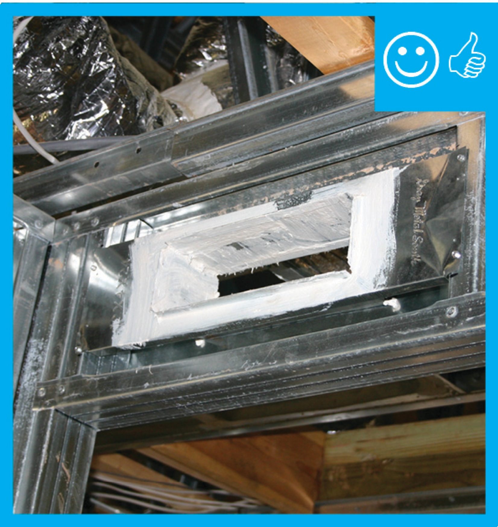
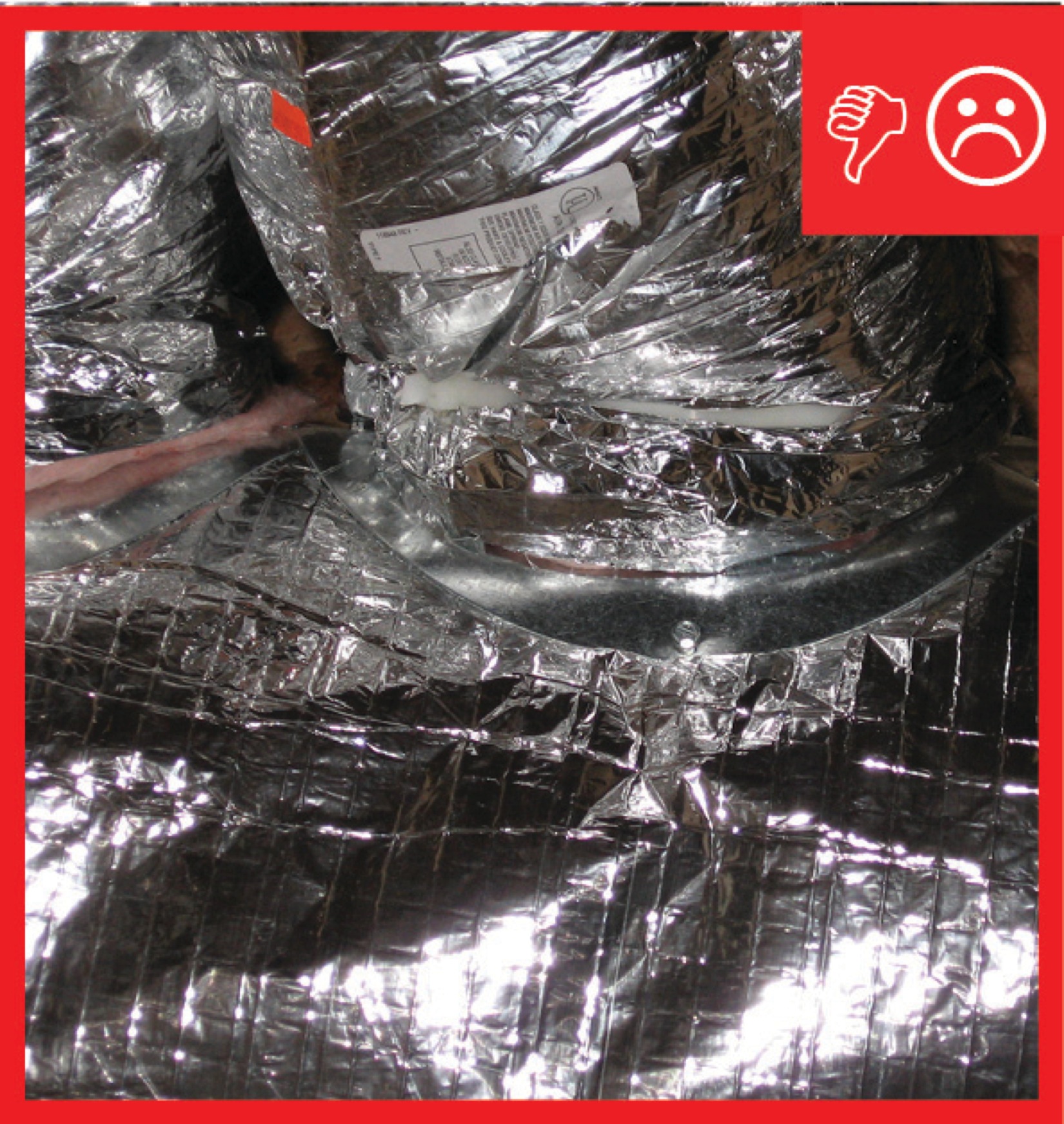
Trunk to duct connections are properly insulated and have been sealed with mastic
Image
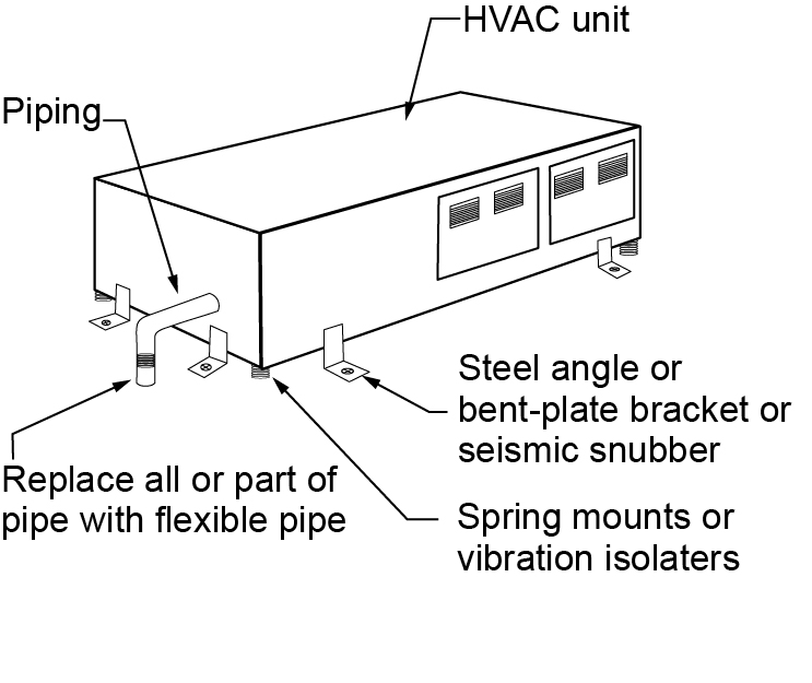
Two L-brackets or seismic snubbers are installed at each corner of the HVAC unit and a vibration isolator or spring mount is installed in each corner to anchor the unit while allowing for slight movement in an earthquake
Image
Two pieces of flex duct are spliced together with a metal sleeve, nylon draw bands, mastic, metal tape, and more mastic
Image

Image
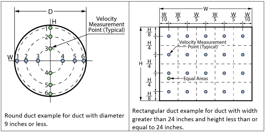
Velocity measurement locations for round and rectangular ducts; velocity measurements should be taken at several locations representative of equal sectional areas across the duct cross-sectional area
Image
Image
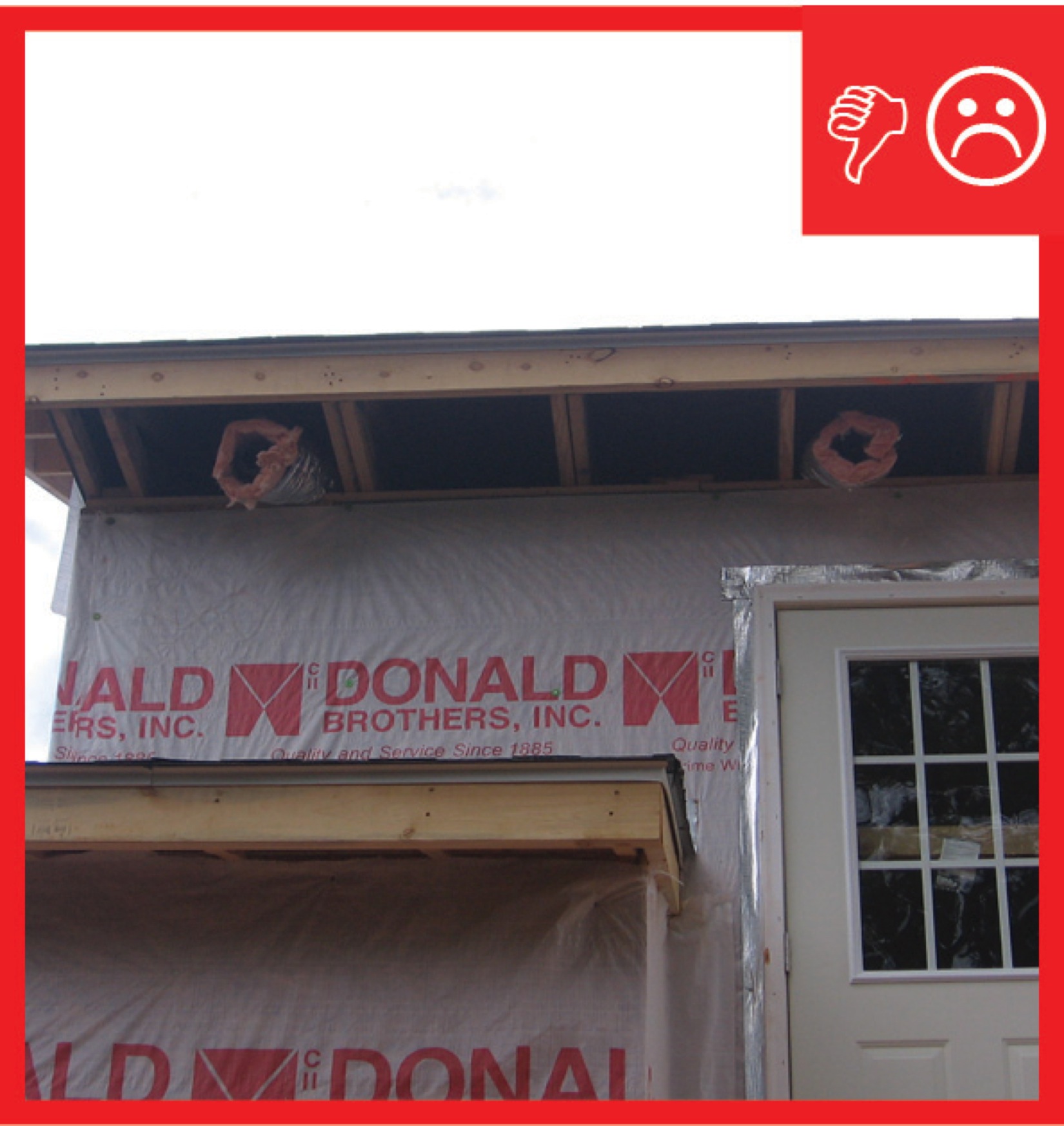
Ventilation air comes directly from outdoors, not from adjacent dwelling units, garages, crawlspaces, or attics
Image
Image
Image
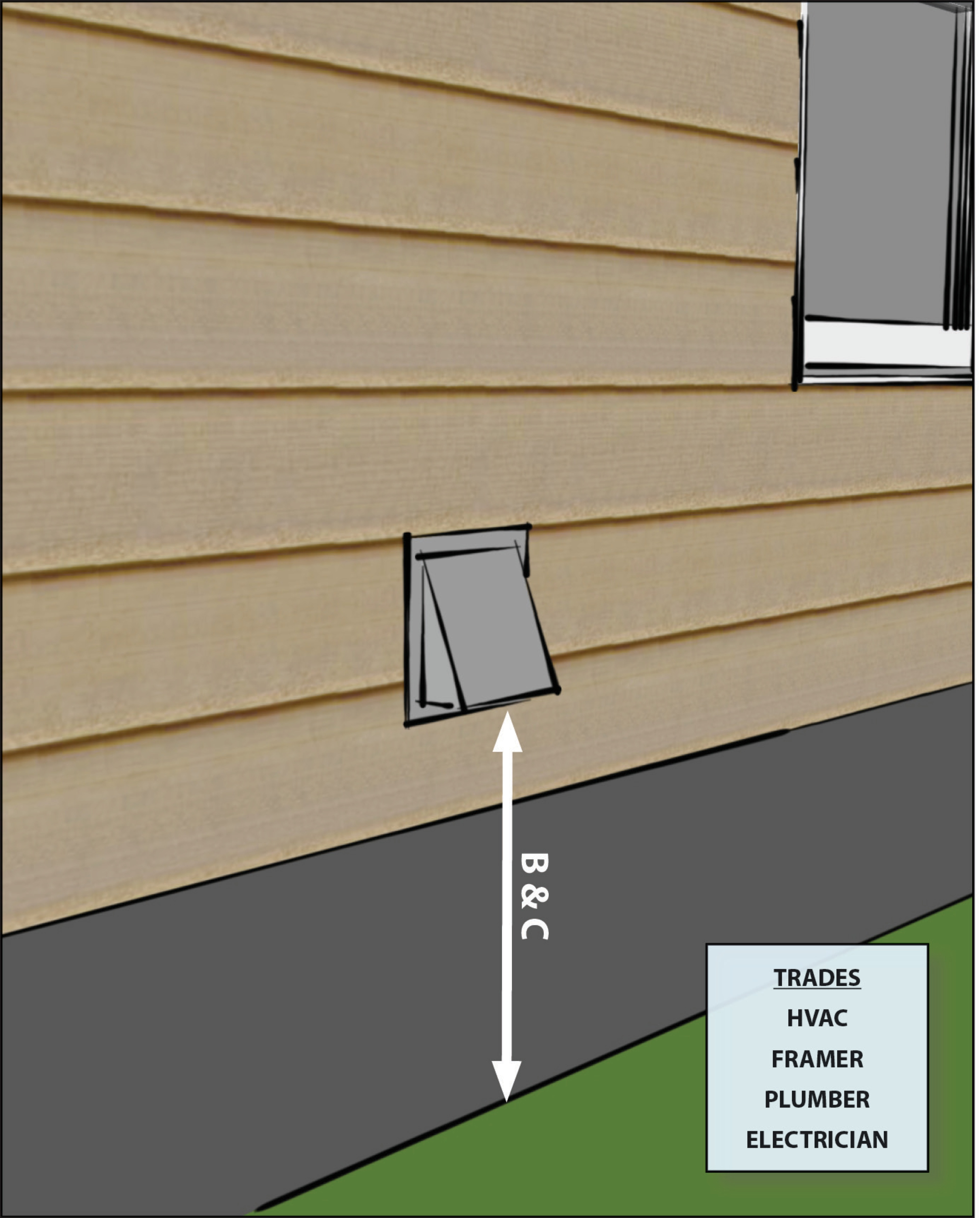
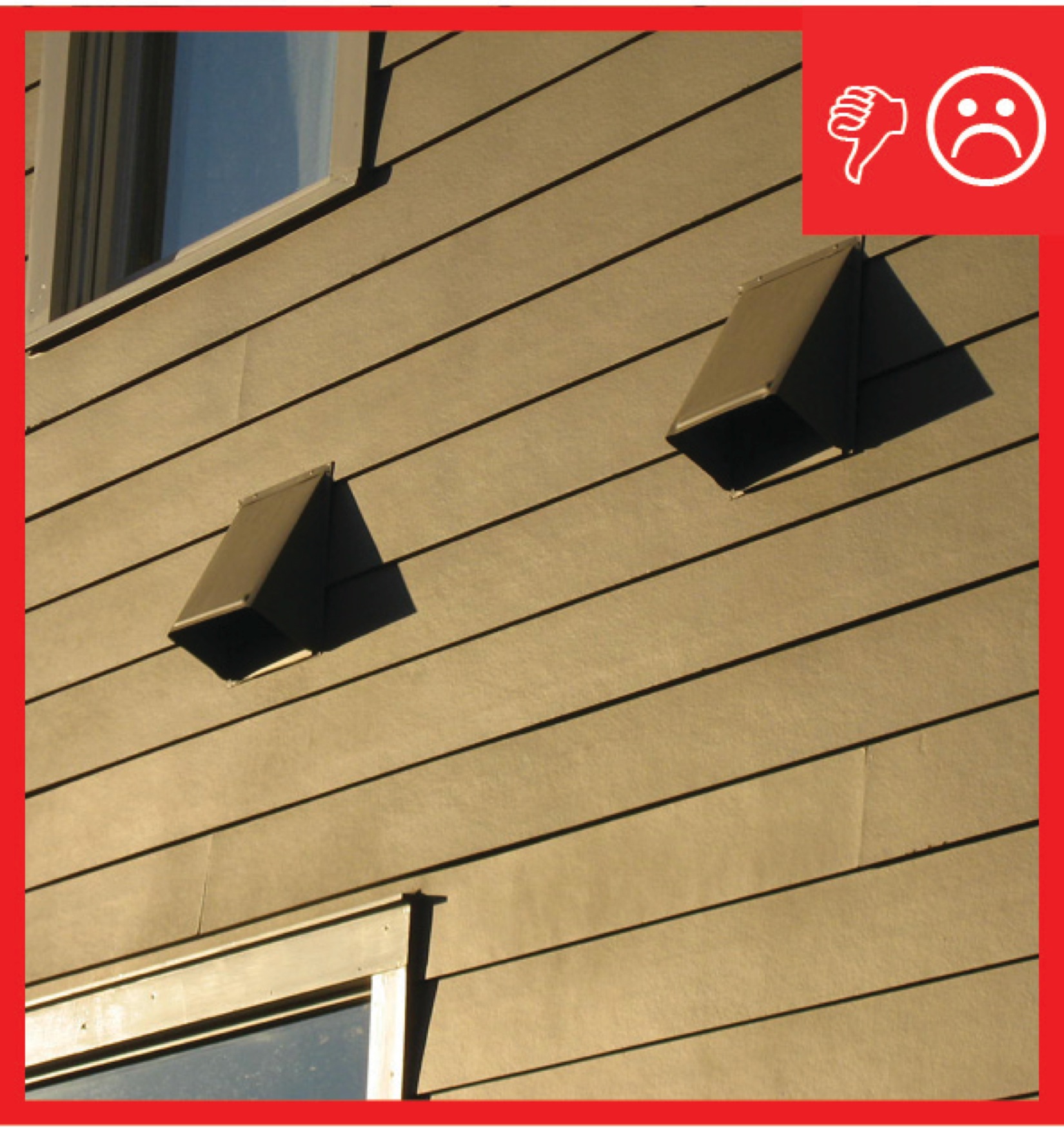
Ventilation air inlets ≥ 2 ft. above grade or roof deck in Climate Zones 1-3 or ≥ 4 ft. above grade or roof deck in Climate Zones 4-8 and not obstructed
Image
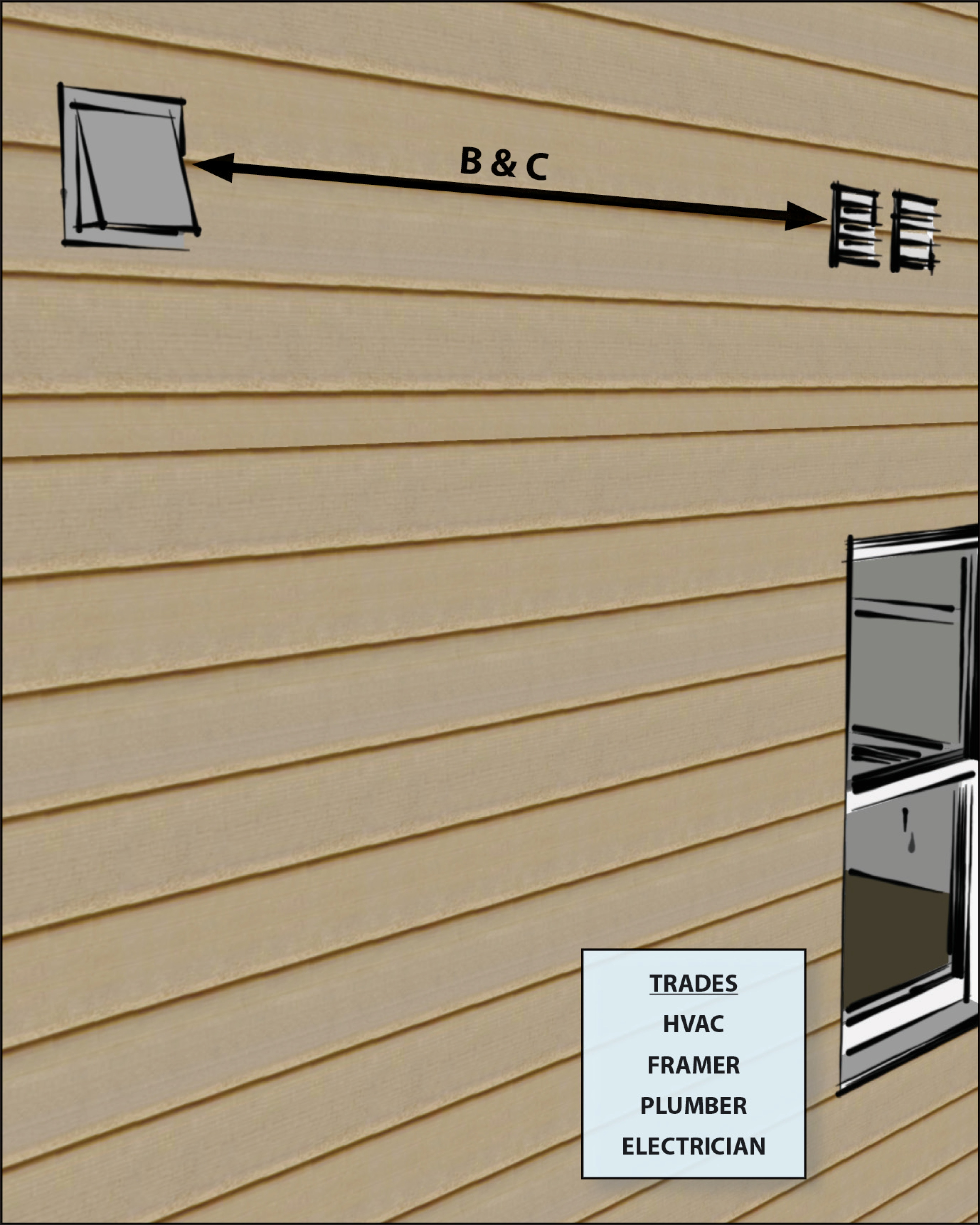
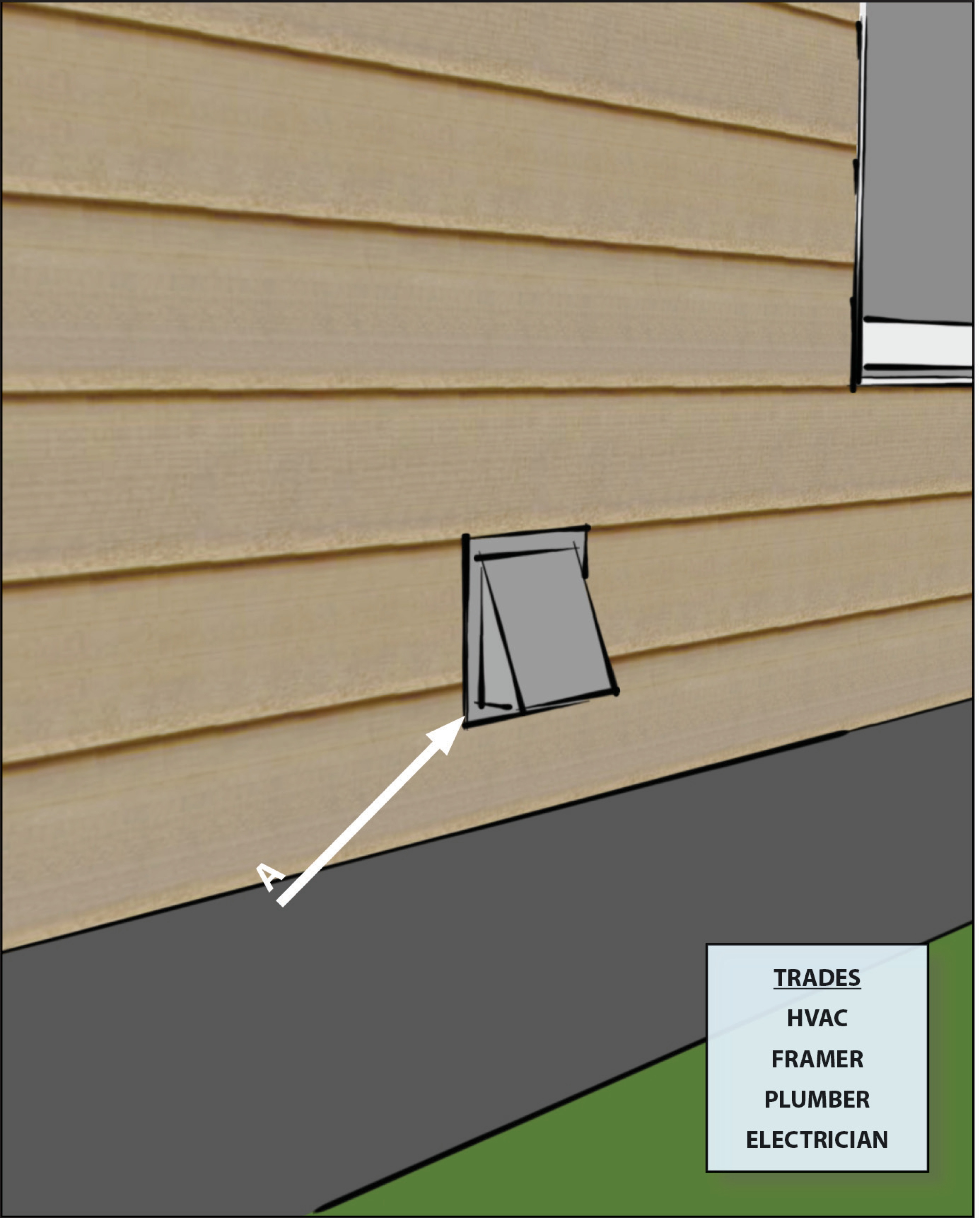
Ventilation air inlets located ≥10 ft. of stretched-string distance from known contamination sources such as stack, vent, exhaust hood, or vehicle exhaust
Image

Ventilation air inlets provided with rodent / insect screen with ≤ 0.5 inch mesh
Image
Image
Image
