Showing results 1 - 82 of 82
Image
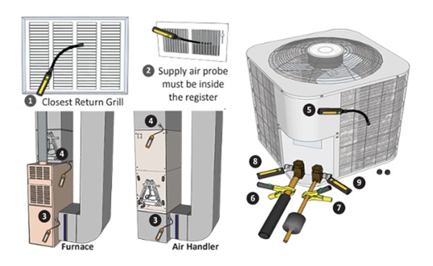
These schematics illustrate temporary deployment locations for probes during the commissioning process; these probes connect to smartphone commissioning applications.
Image
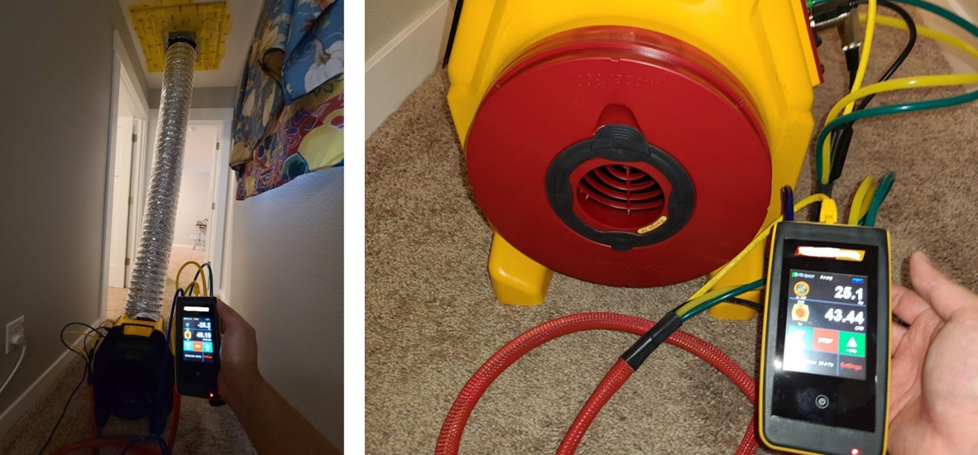
A duct leakage test is performed on a ducted heat pump system using a duct tester (blower fan) and a digital manometer.
Image
A flow grid is inserted into the filter grille/slot to directly measure airflow.
Image
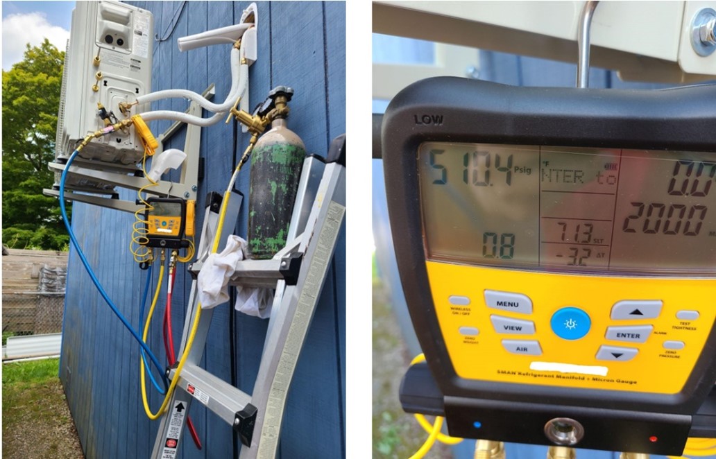
A nitrogen pressure test was completed on this ductless mini-split heat pump using a digital manifold gauge.
Image
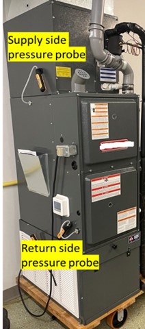
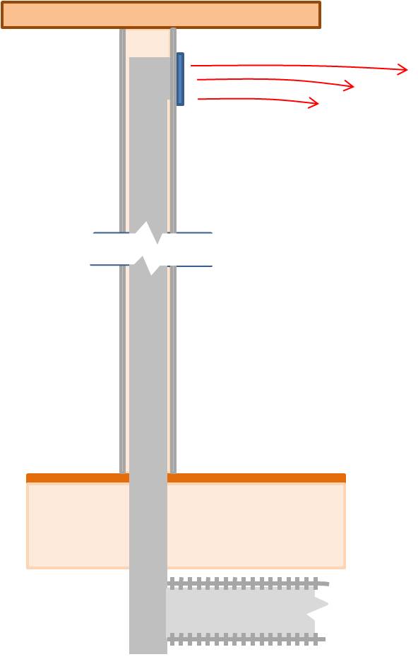
A static pressure measurement is taken on this air handler using probes on the supply and return sides of the fan.
Image
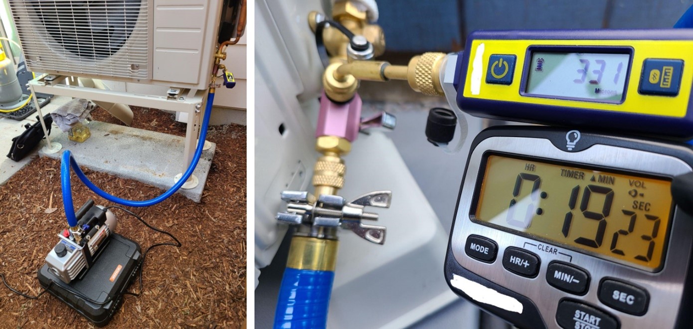
A vacuum decay test is performed on this ductless mini-split heat pump using a digital micron gauge for accurate measurement; a deep vacuum is achieved quickly by using large diameter, vacuum-rated hoses, and removing valve cores
Image
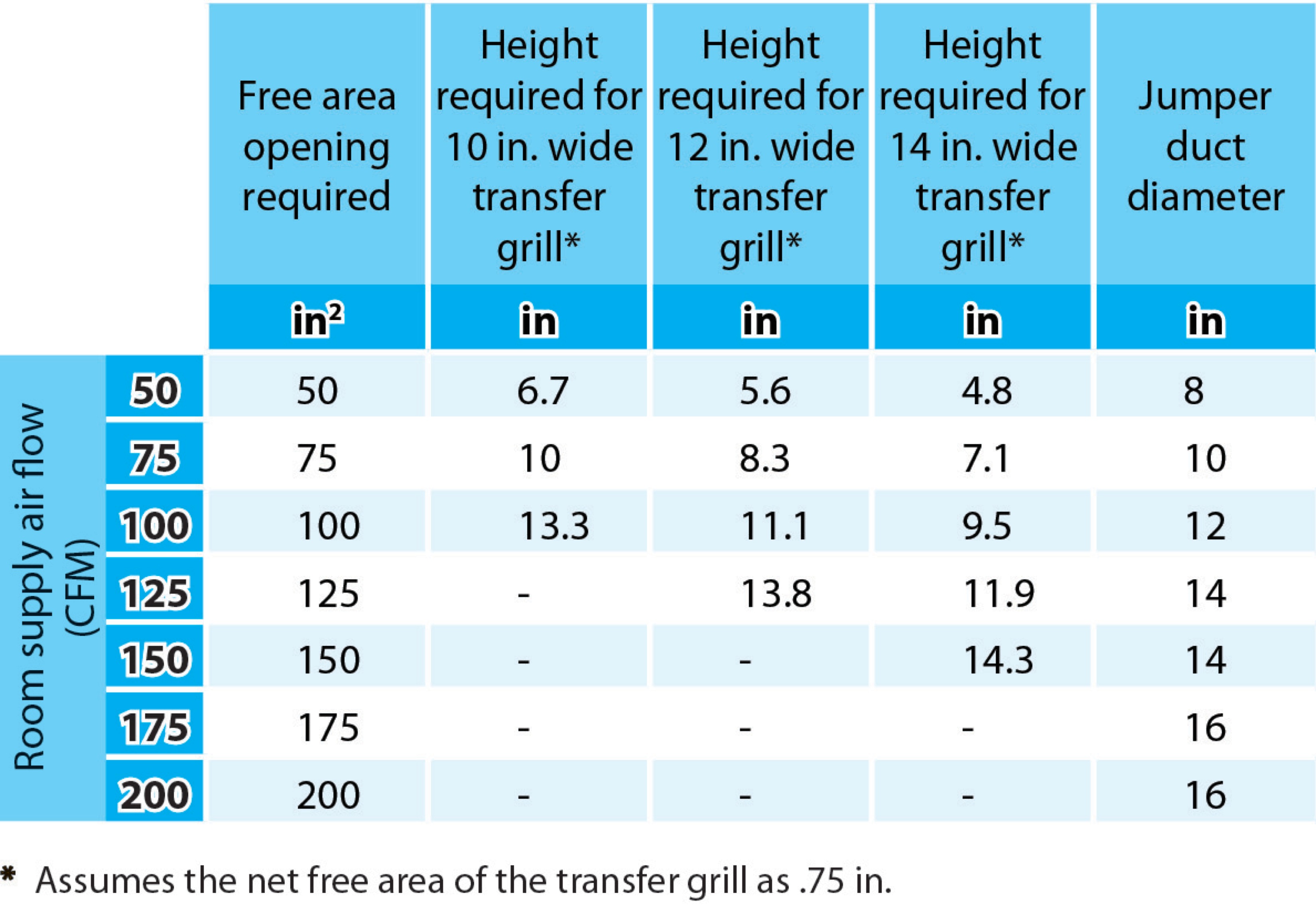
Bedrooms pressure-balanced and provide 1 sq. in. of free area opening per 1 CFM of supply air or achieve a Rater-measured pressure differential ≤ 3 Pa
Image

Bedrooms pressure-balanced and provide 1 sq. in. of free area opening per 1 CFM of supply air or achieve a Rater-measured pressure differential ≤ 3 Pa
Image
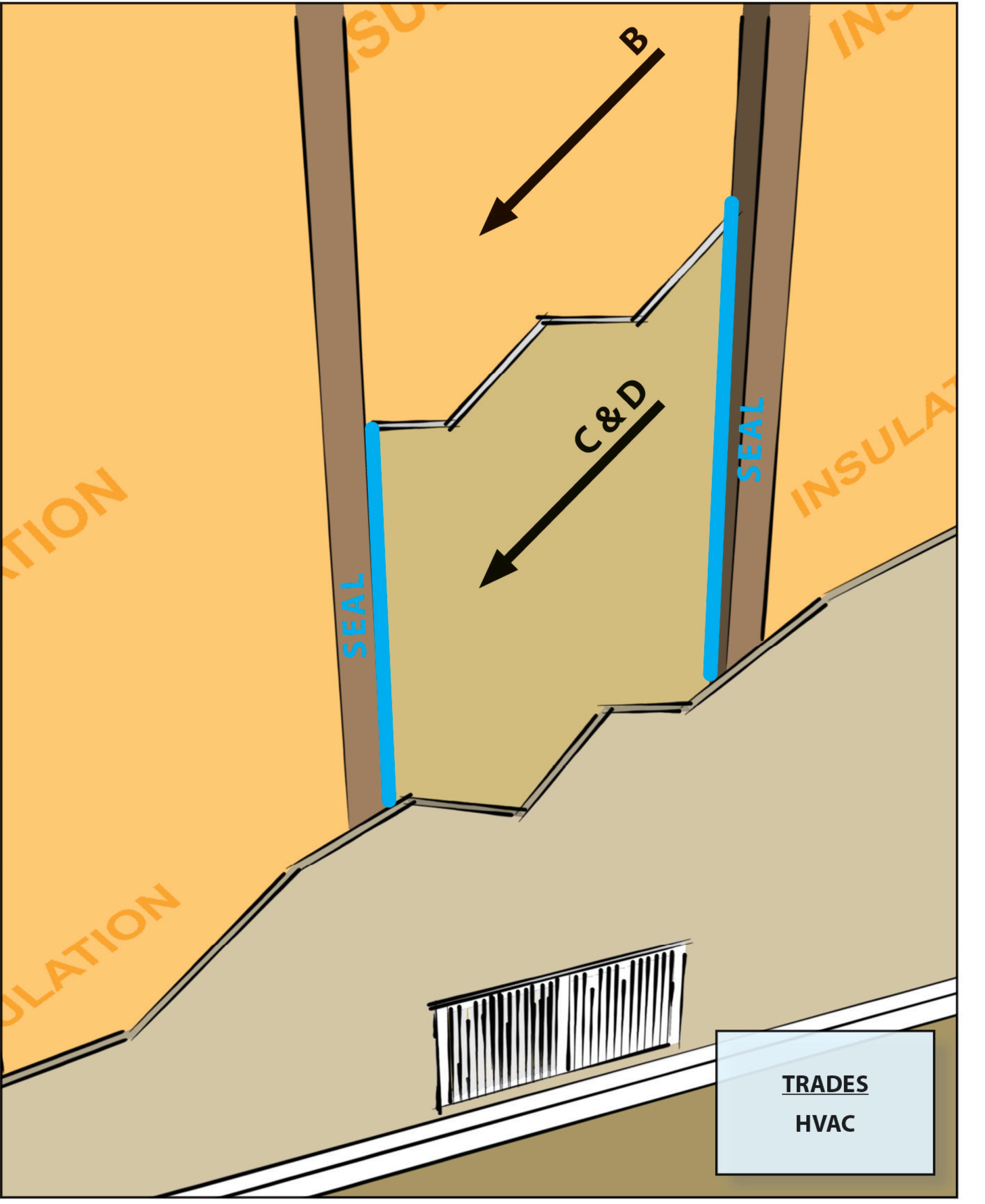
Building cavities not used as supply or return ducts unless they meet Items 3.2, 3.3, 4.1, and 4.2 of this Checklist
Image
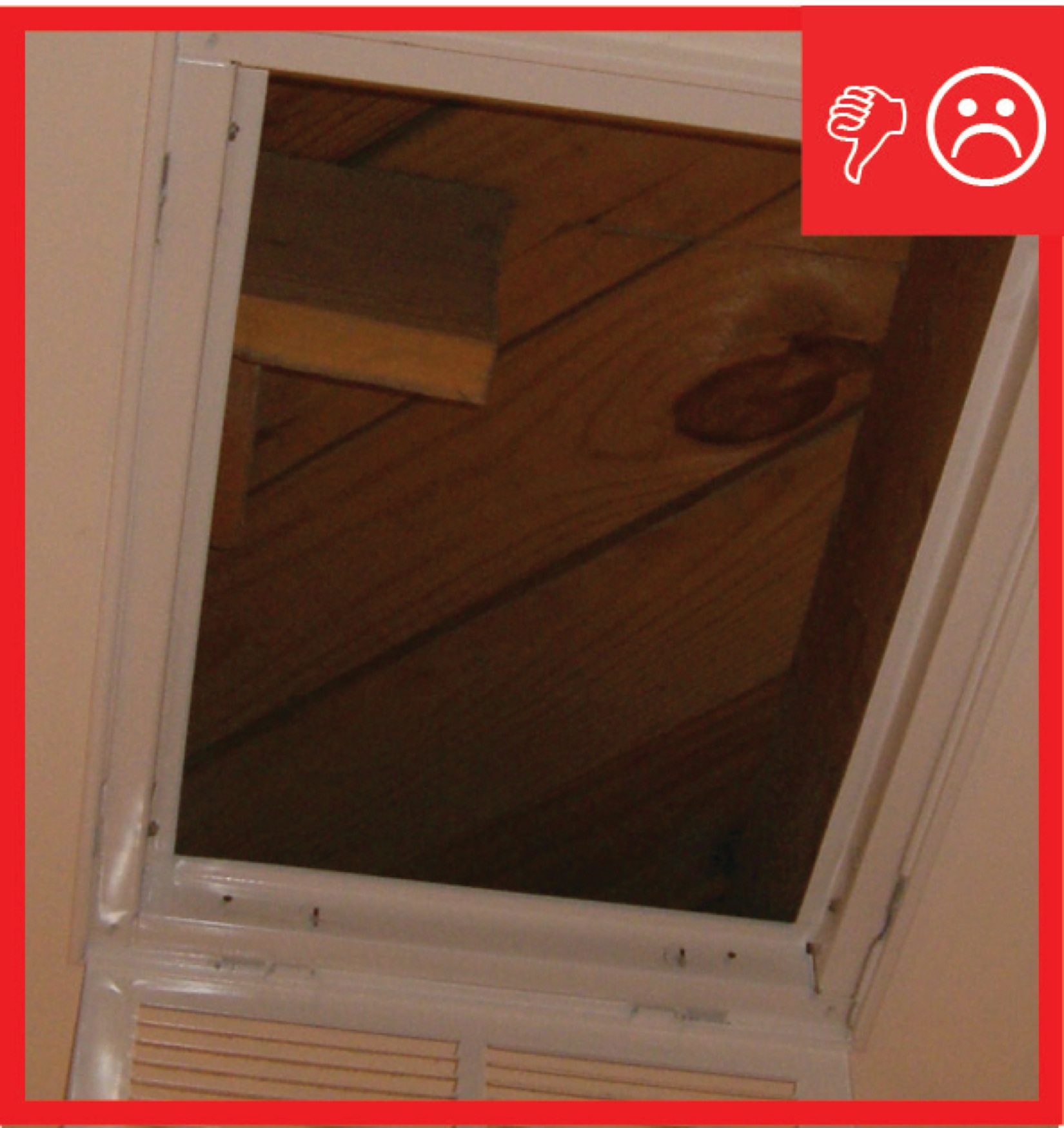
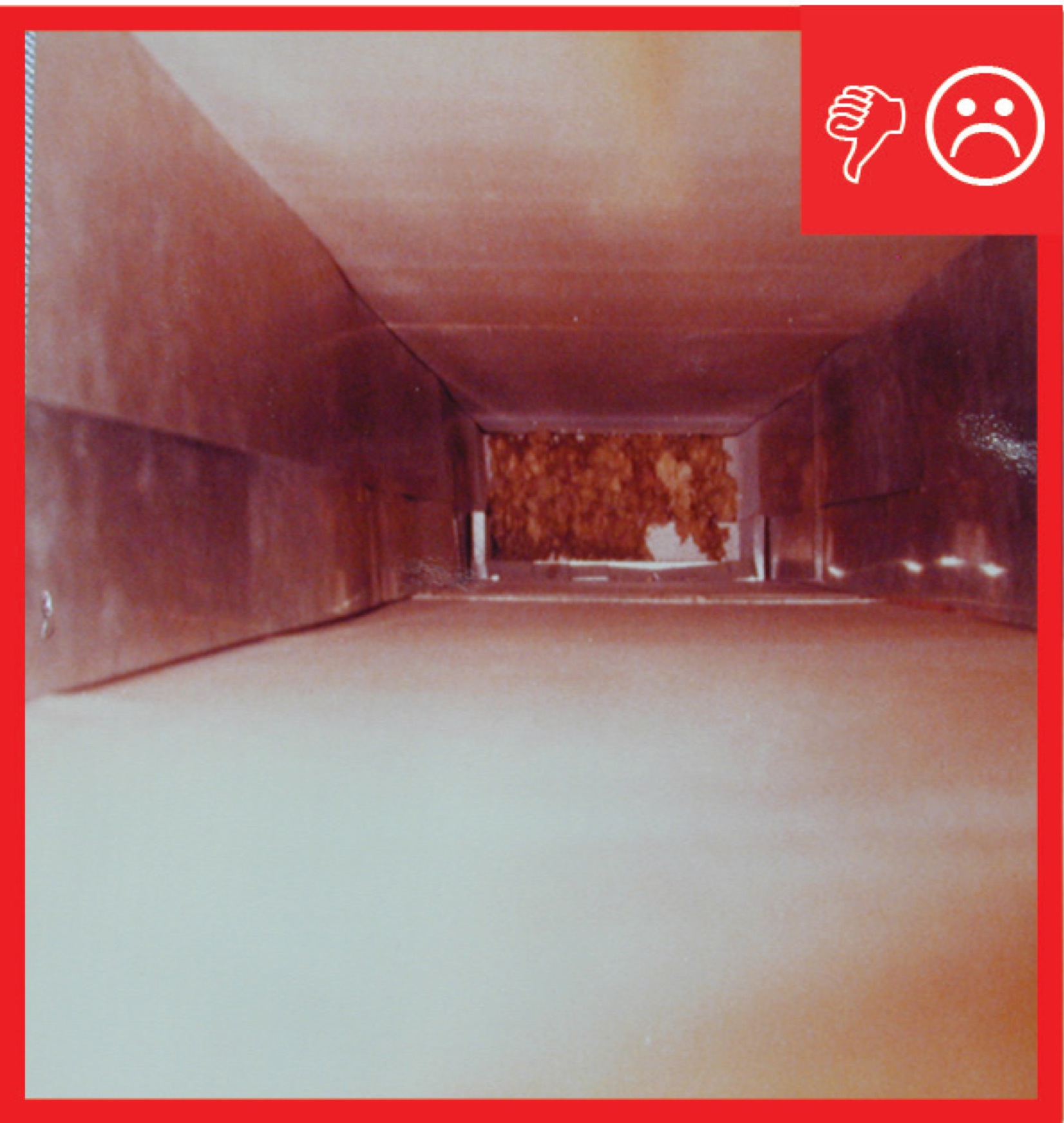
Cavity used for return is not insulated and is not air sealed, which will pull in air from outside
Image
Image
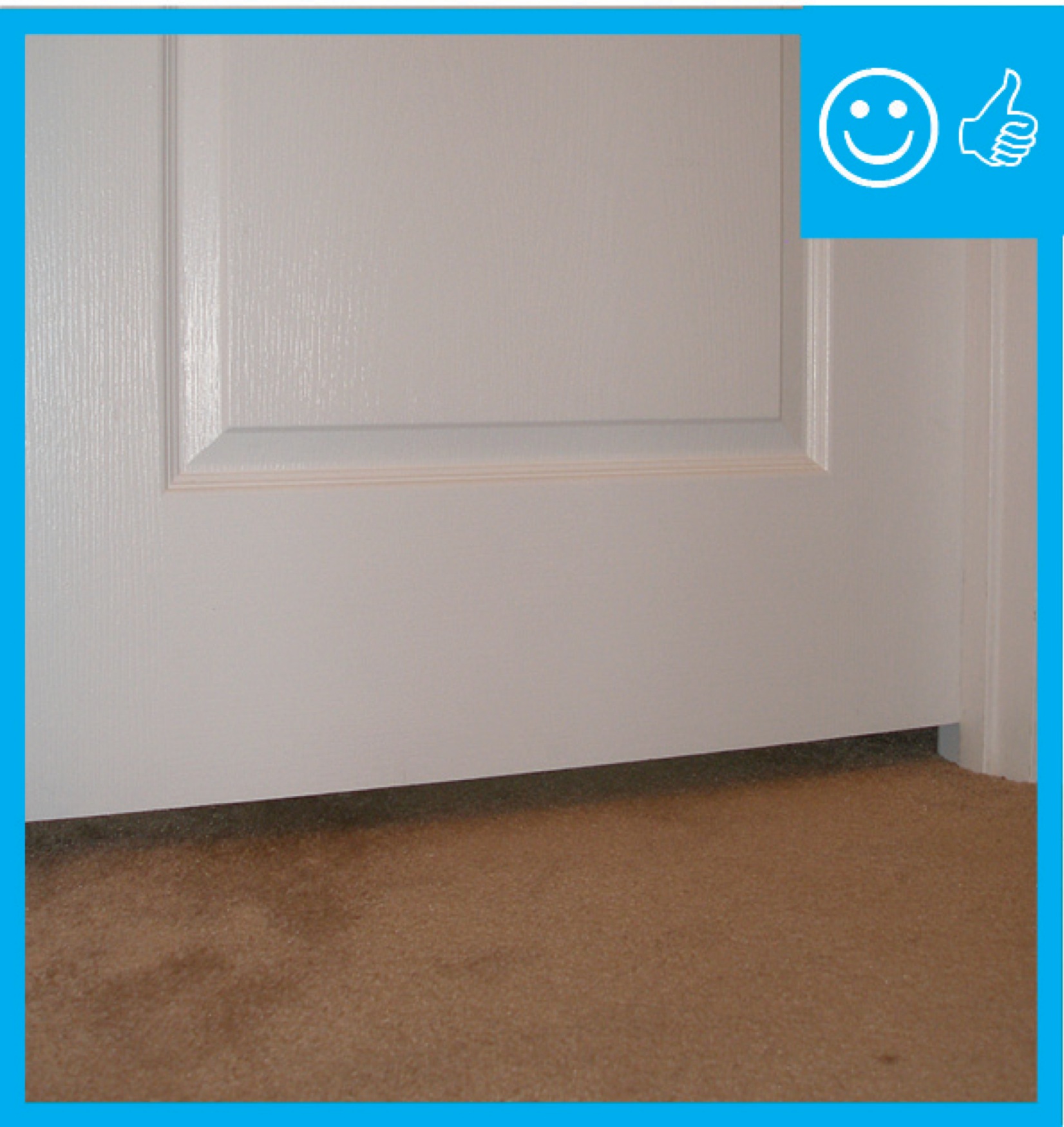
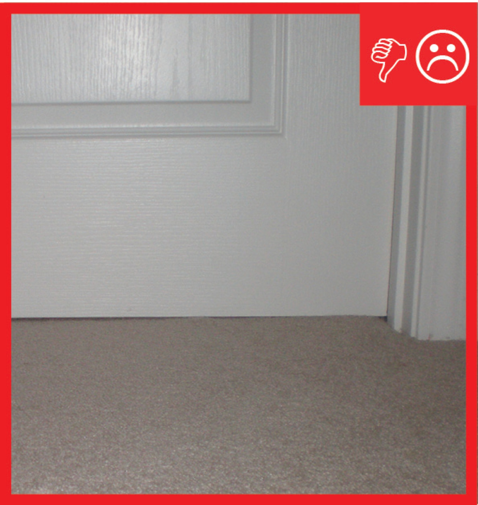
Door has been undercut to allow for specified amount of air flow therefore contributing to pressure balancing
Image
Image
Image
Image
Image
Image
Image
Image
Image
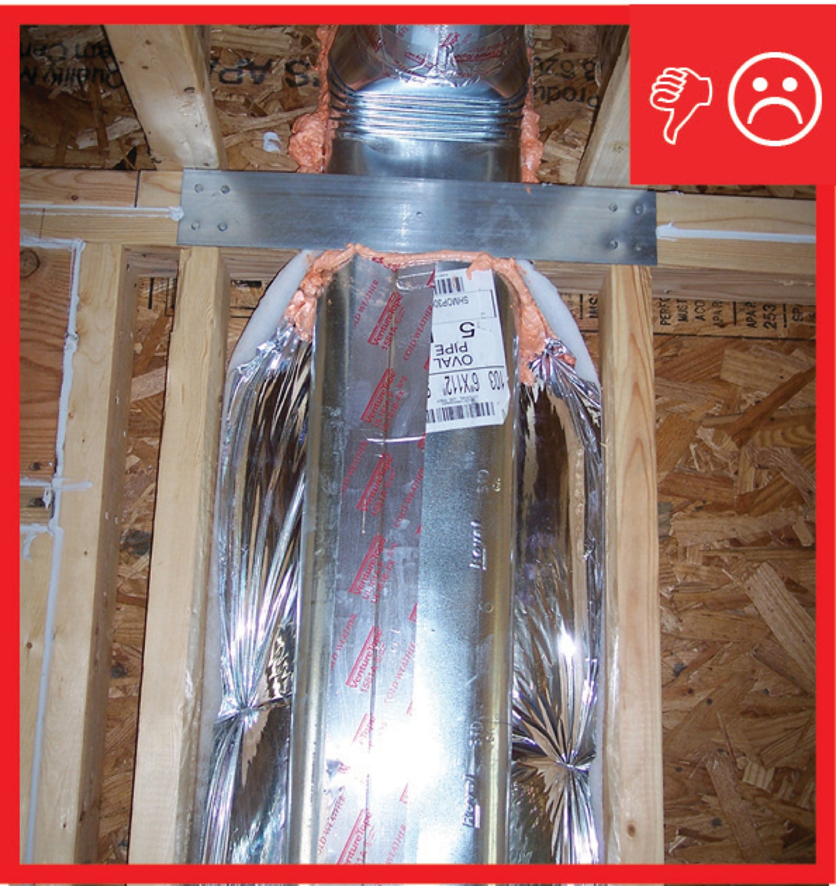
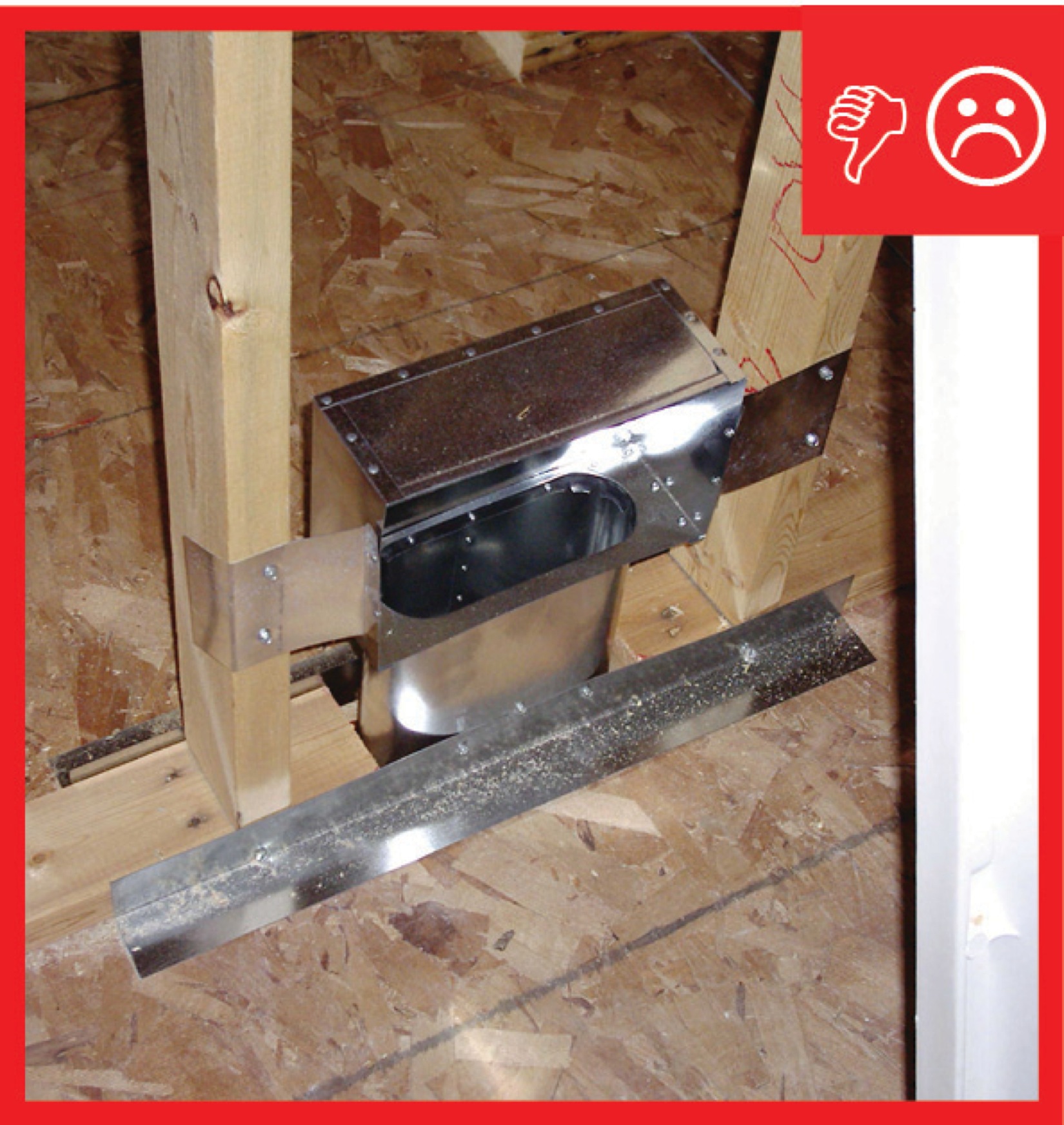
Duct to boot connection of jump duct not fastened and sealed
Image
Image
Image
Image
Image
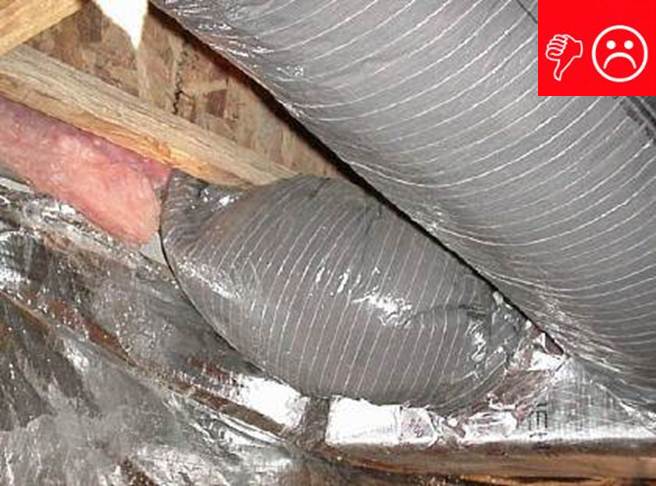
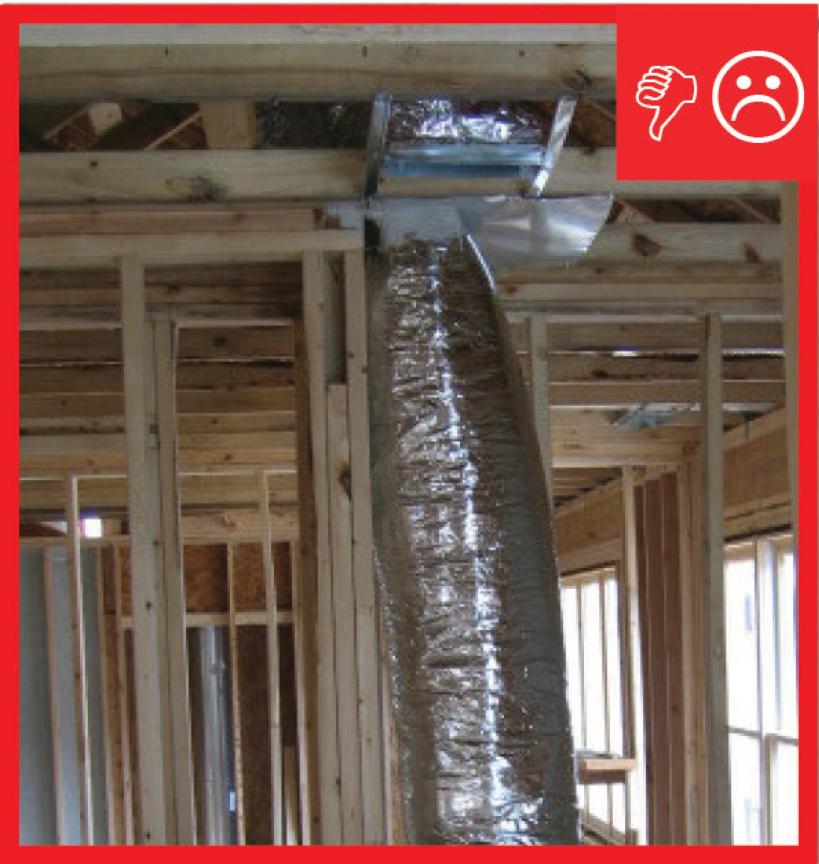
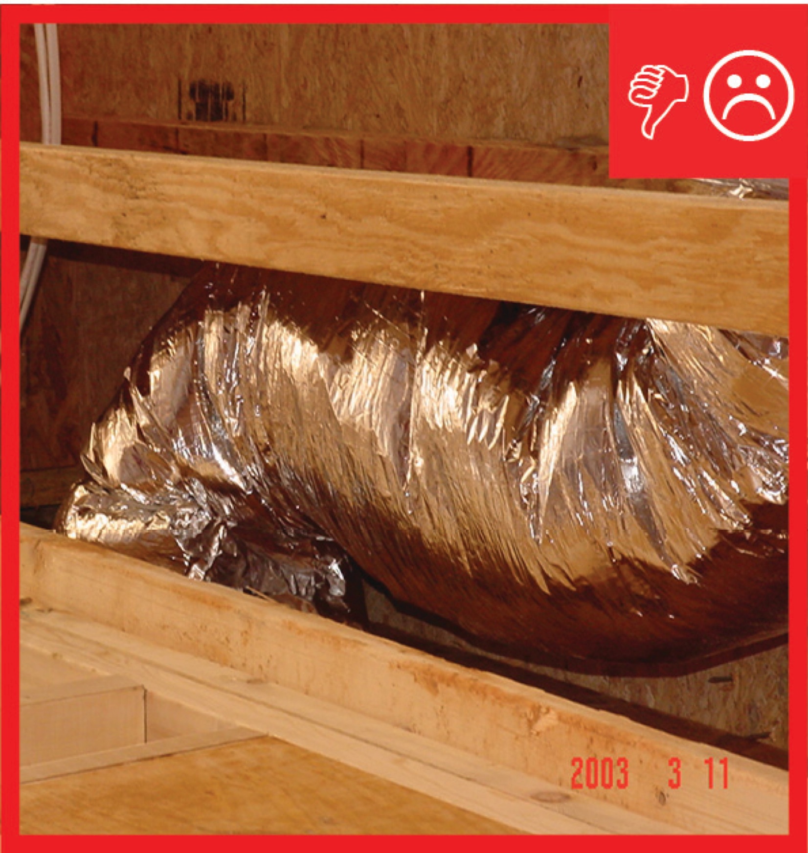
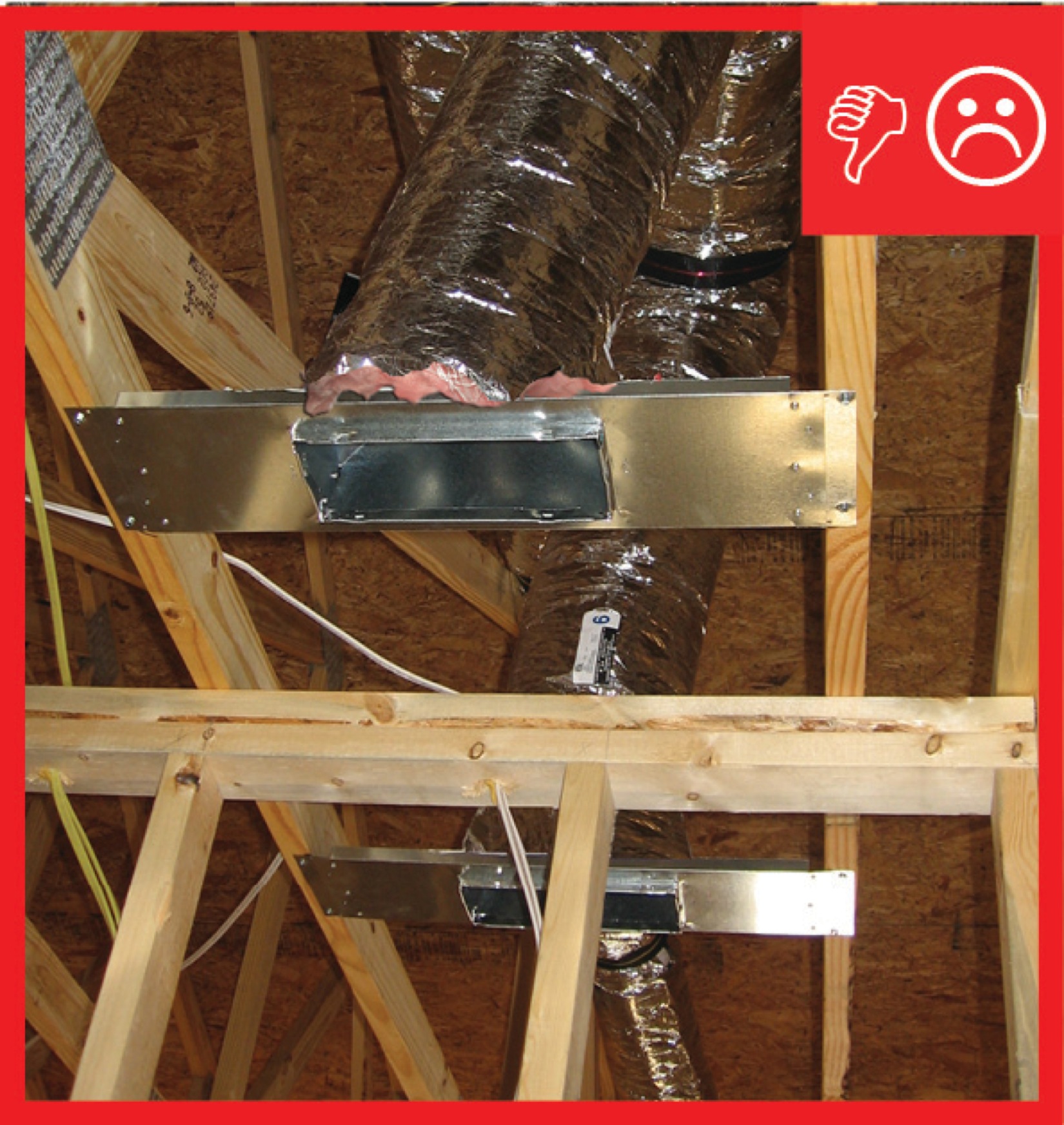
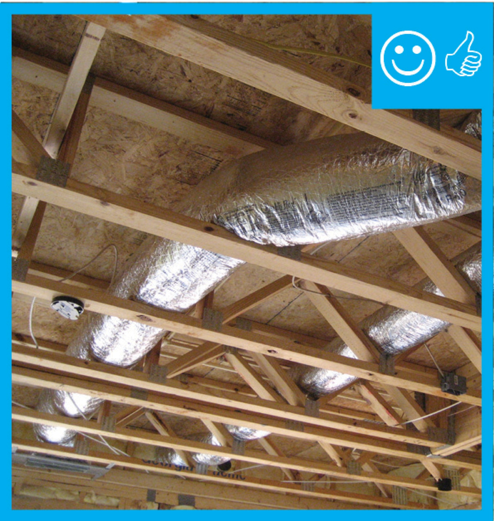
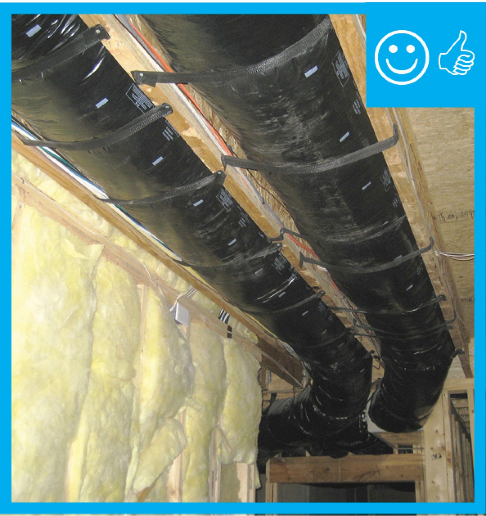
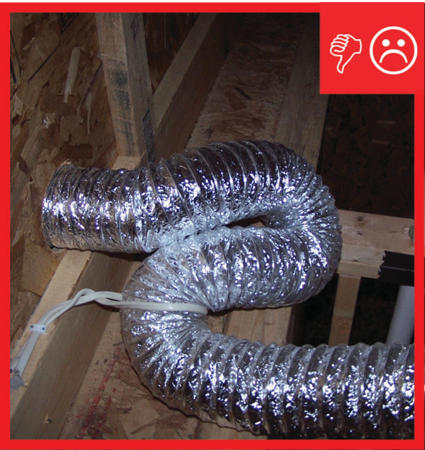
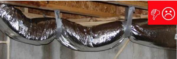
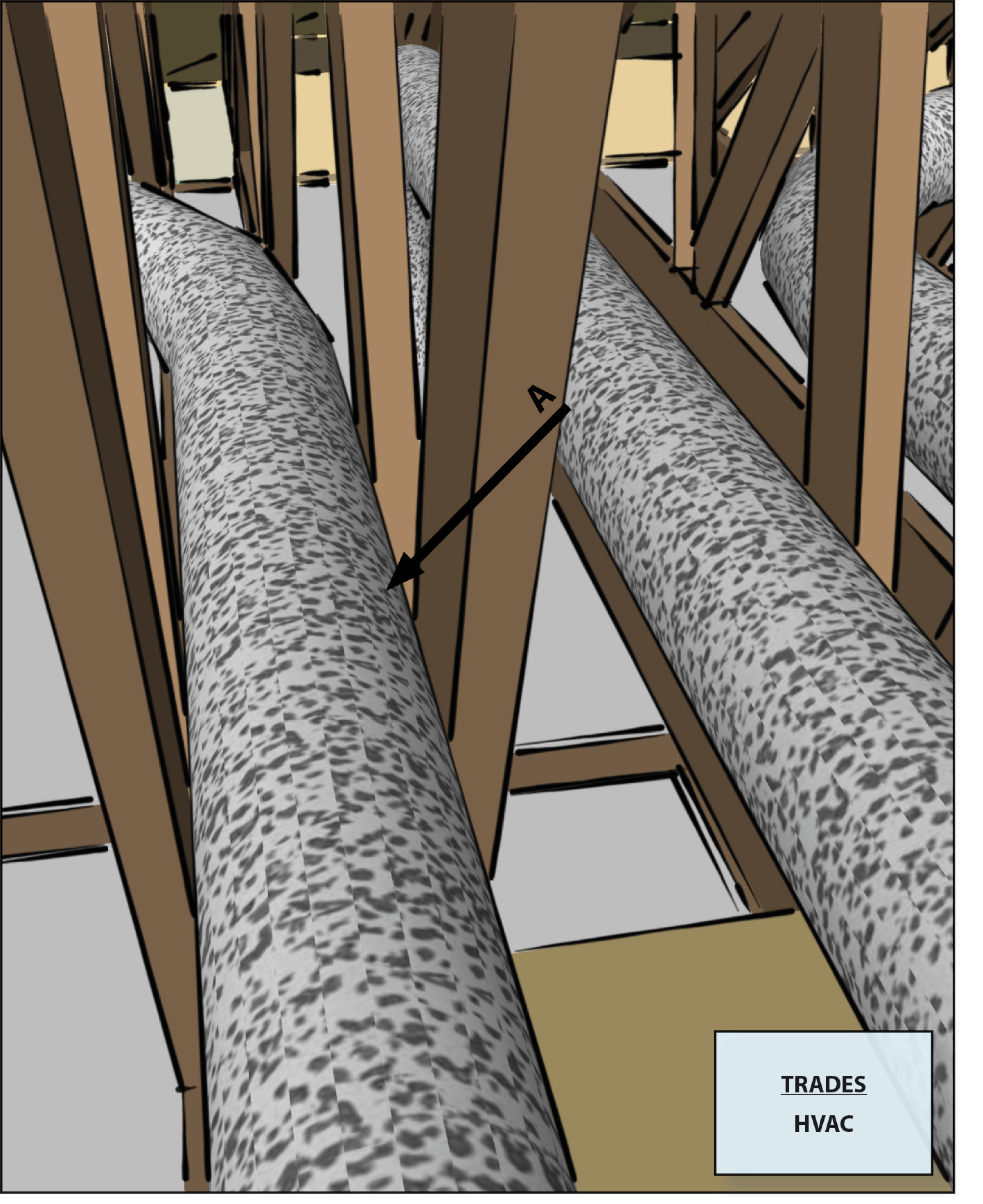
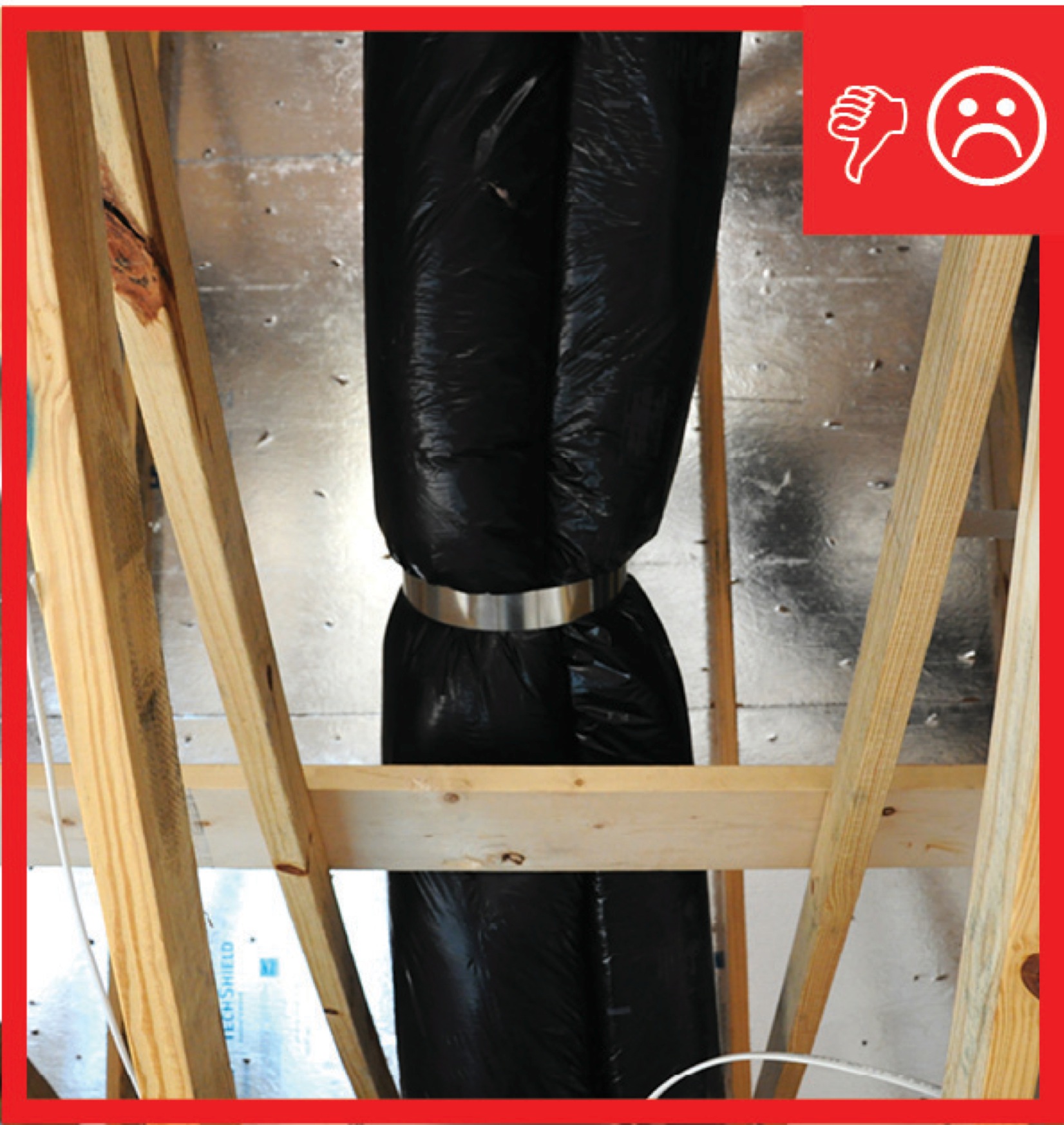
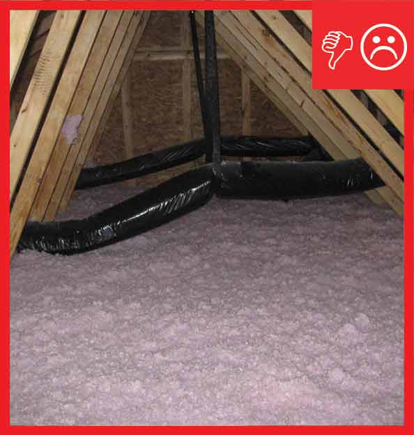
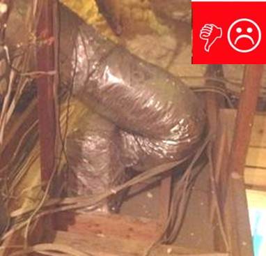
Ducts sagging because supports not installed at regular intervals
Image
Image
Image
Image
Image
Image
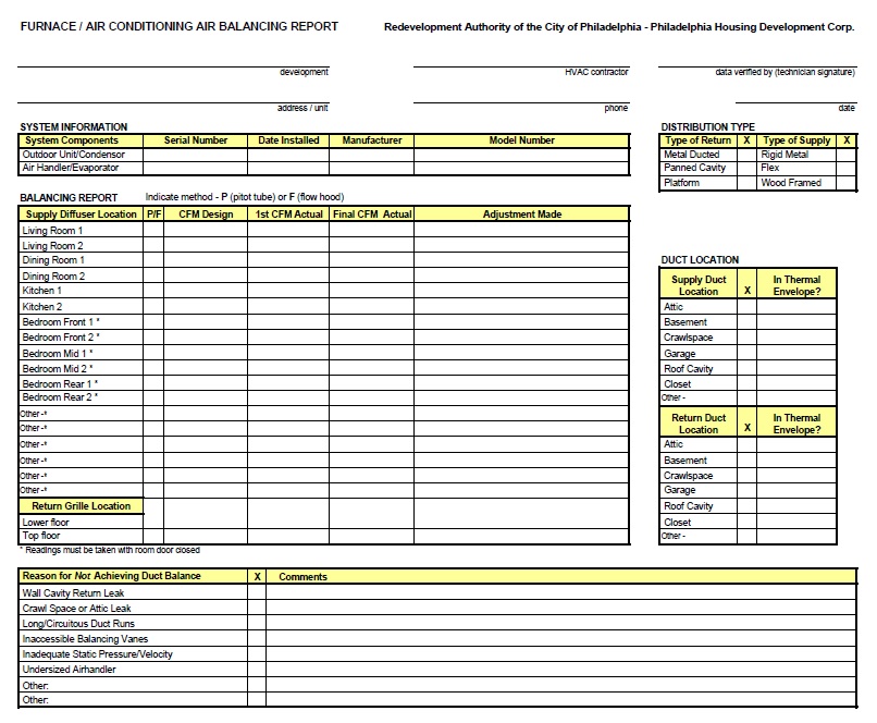
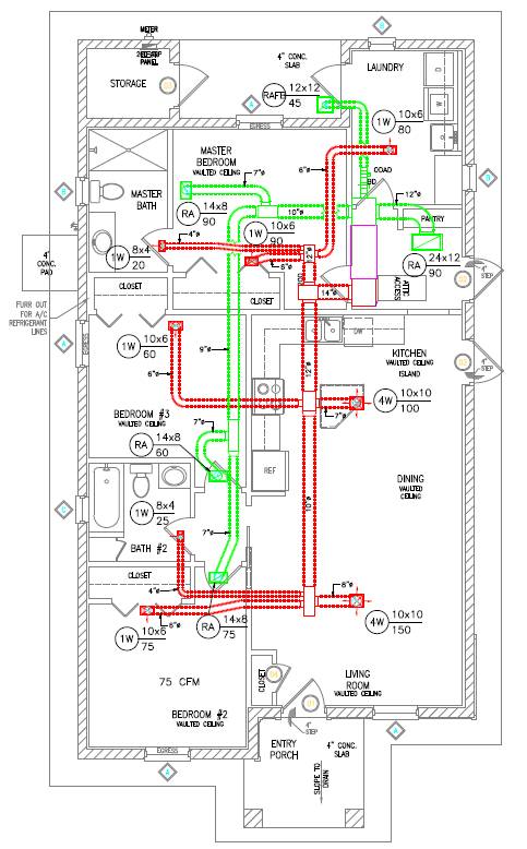
Example of an HVAC installer’s balancing report form
Image
Image
Image
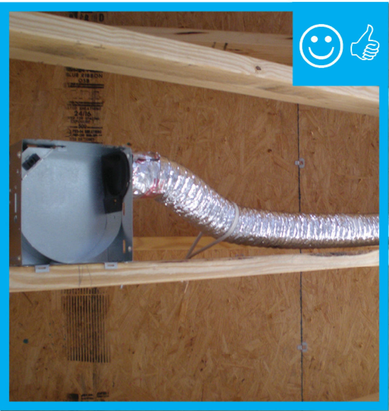
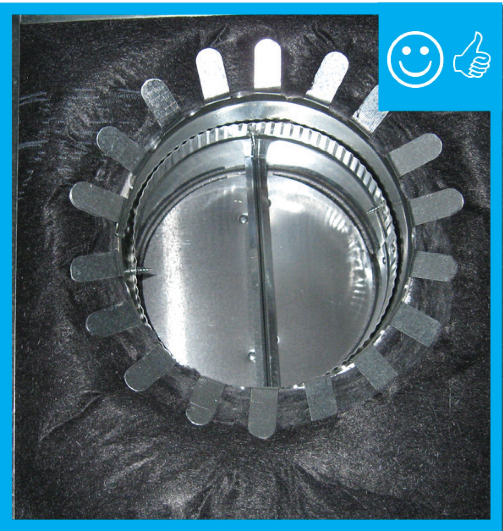
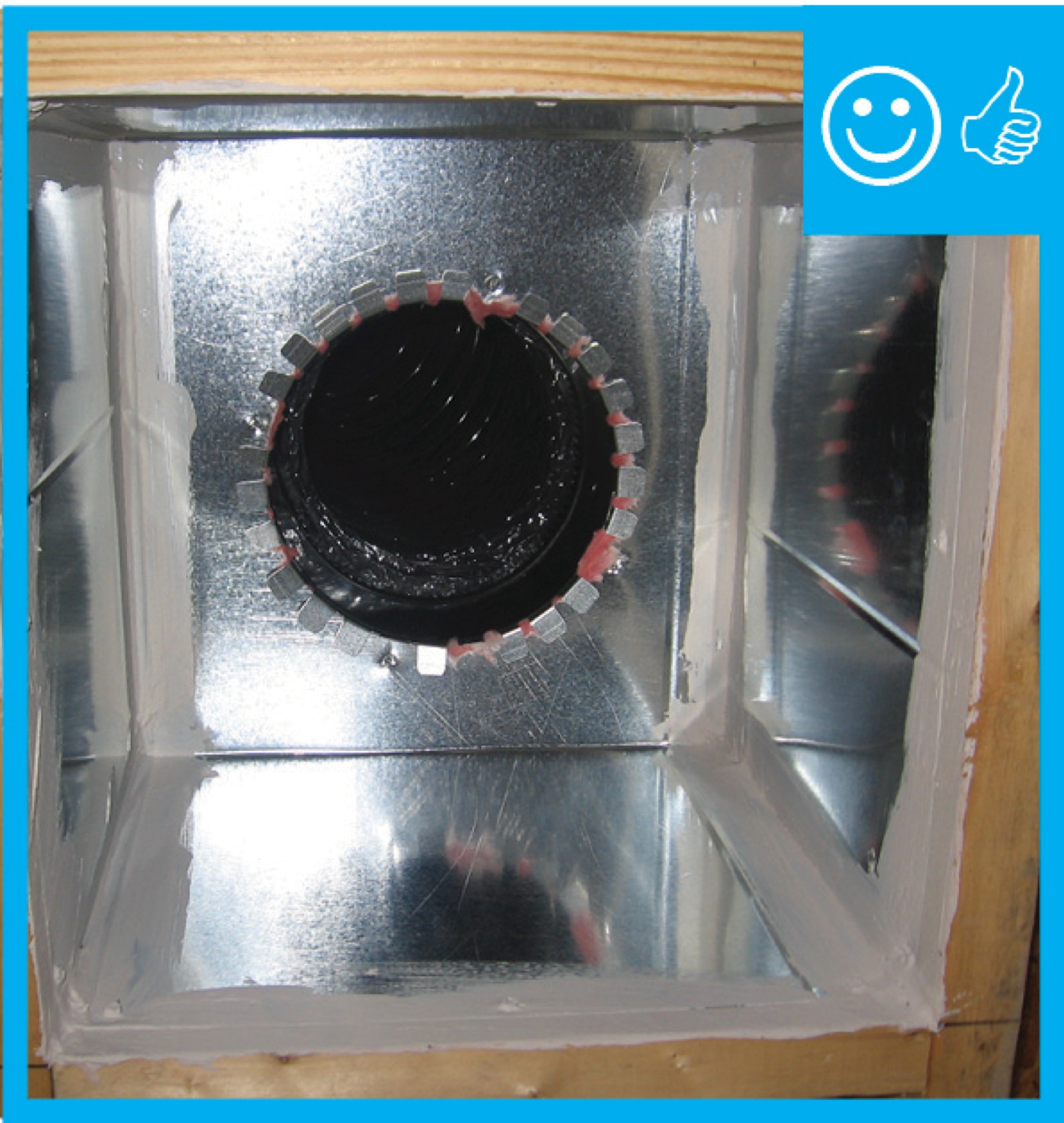
Fan housing was oriented in the correct direction to allow proper exhaust duct installation
Image
Image
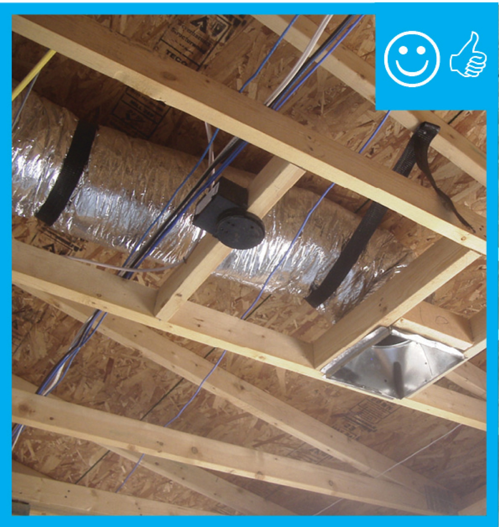
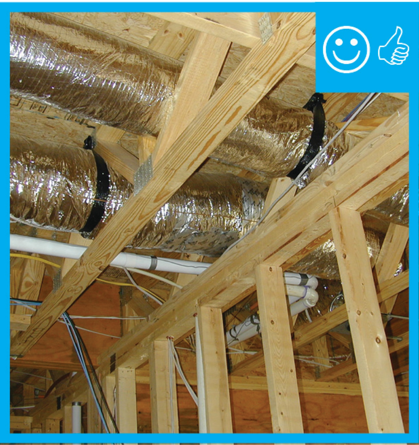
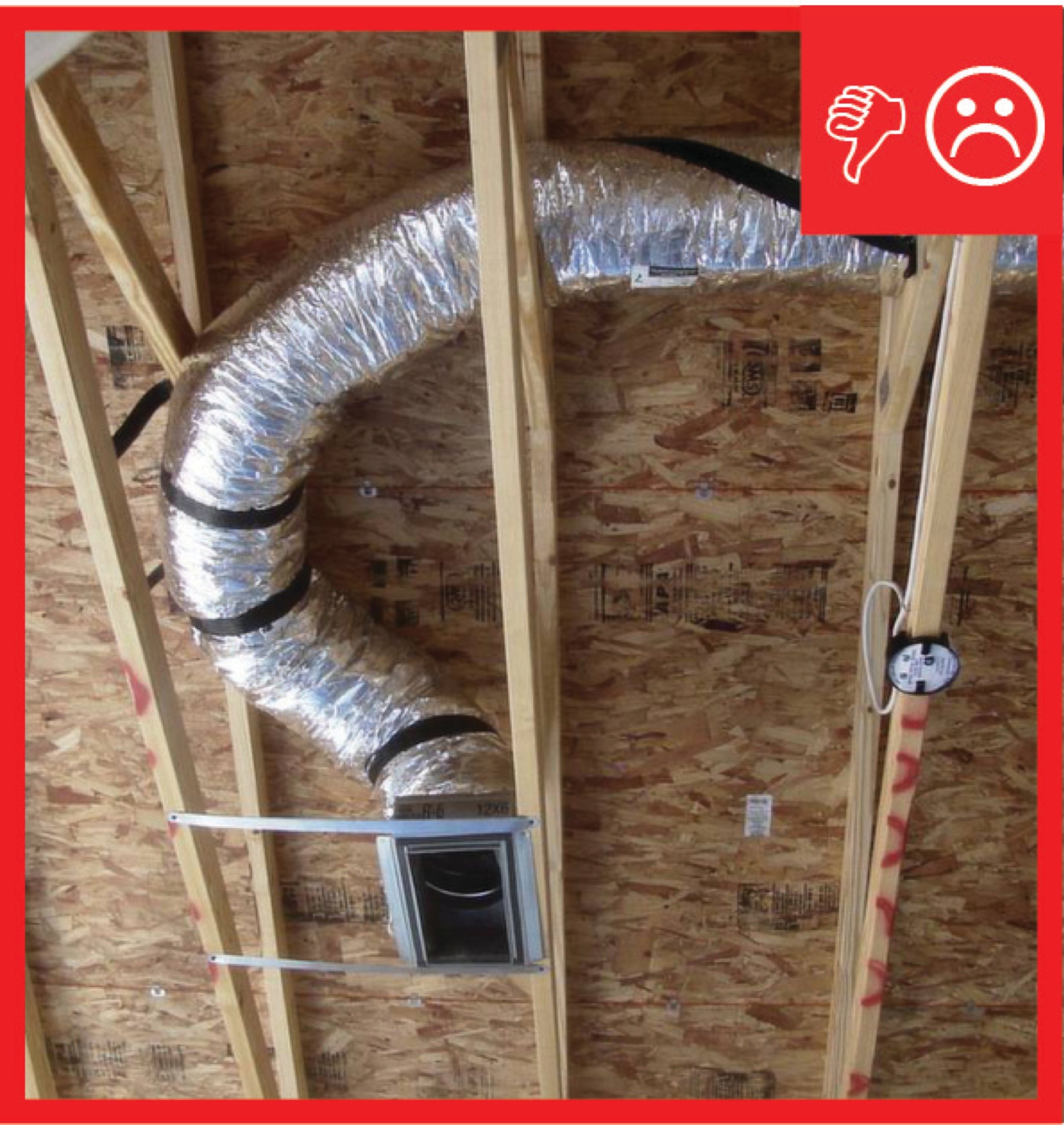
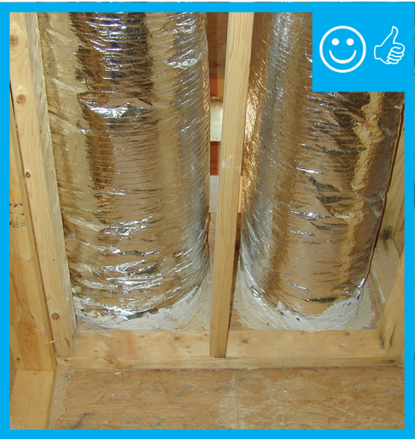
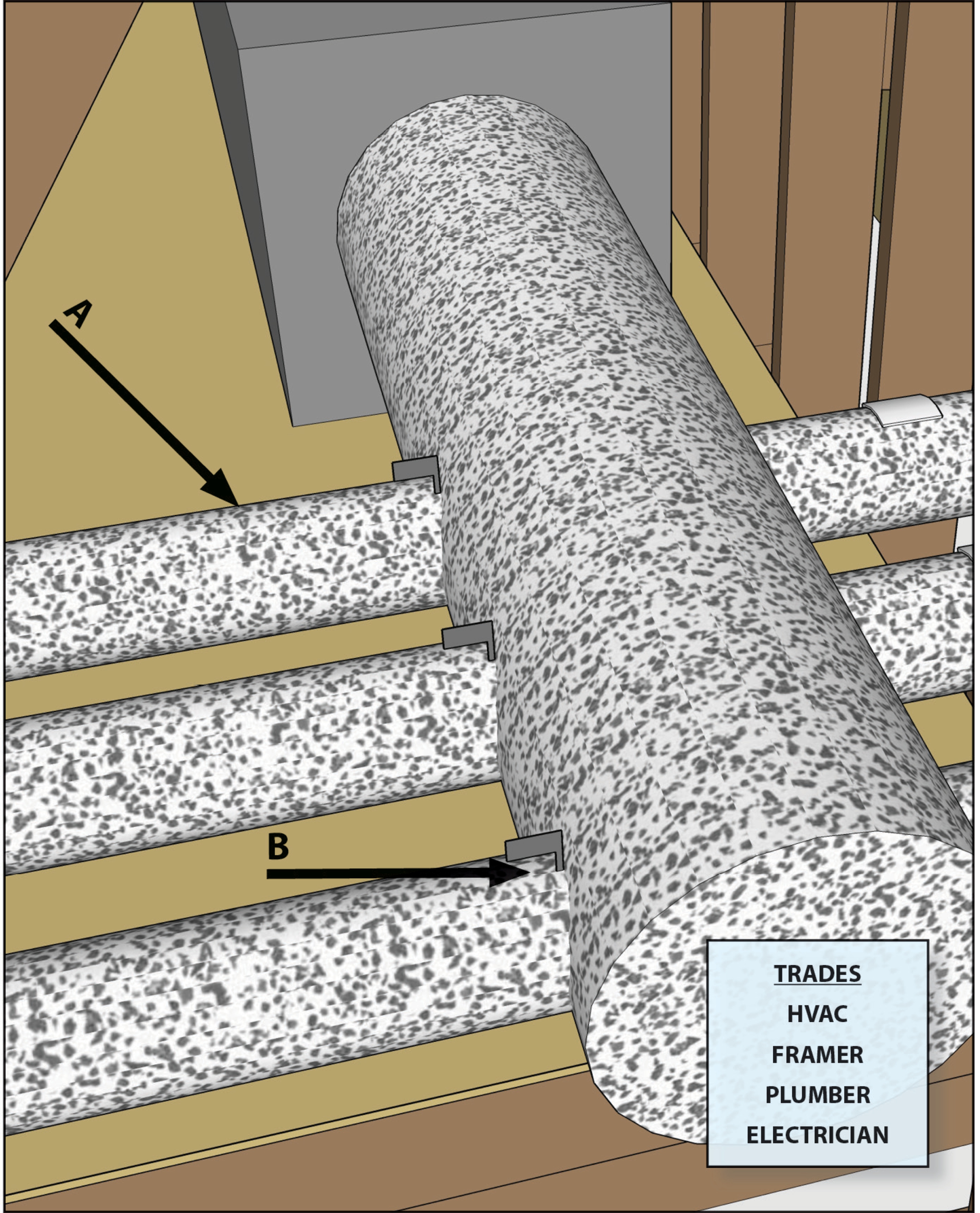
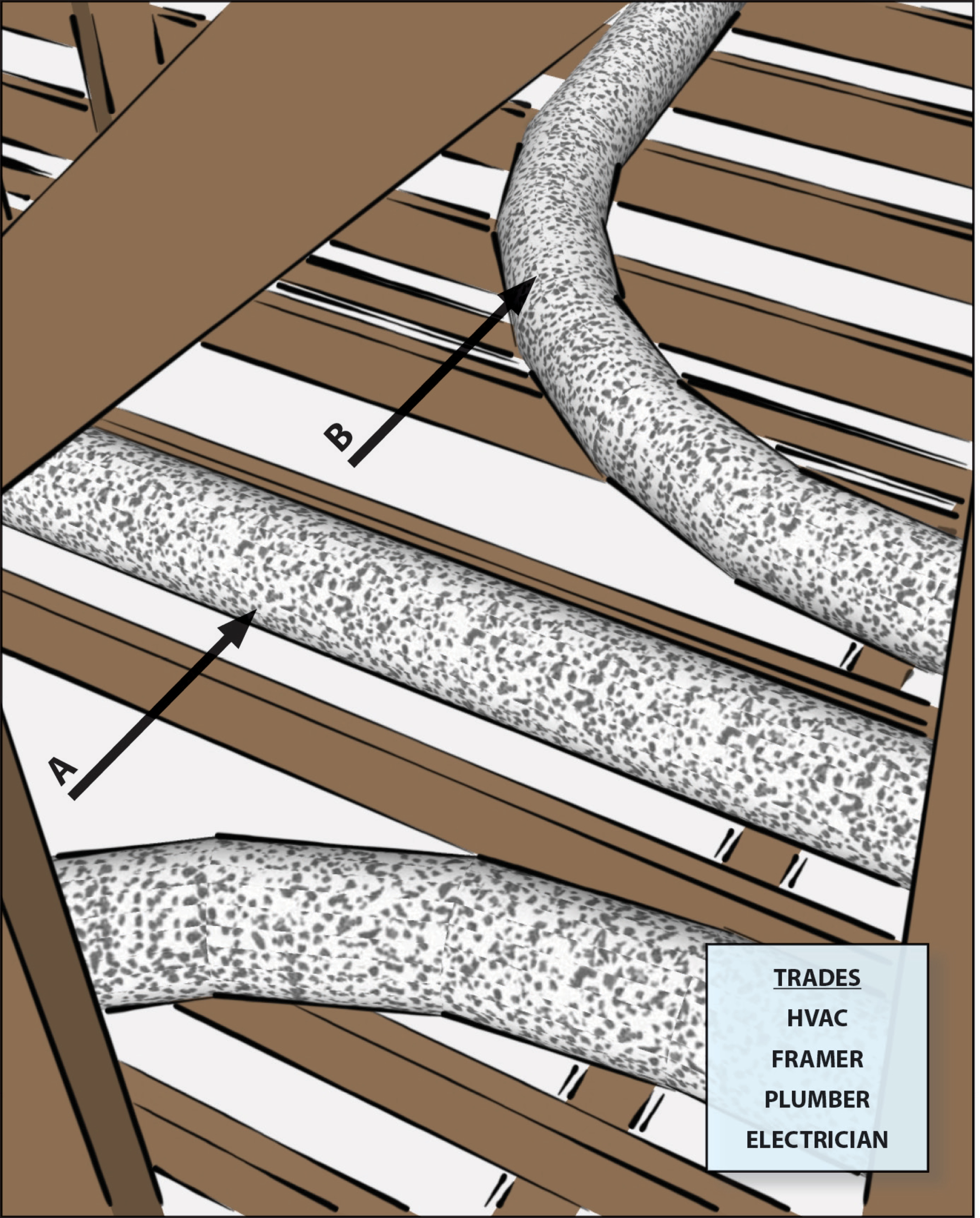
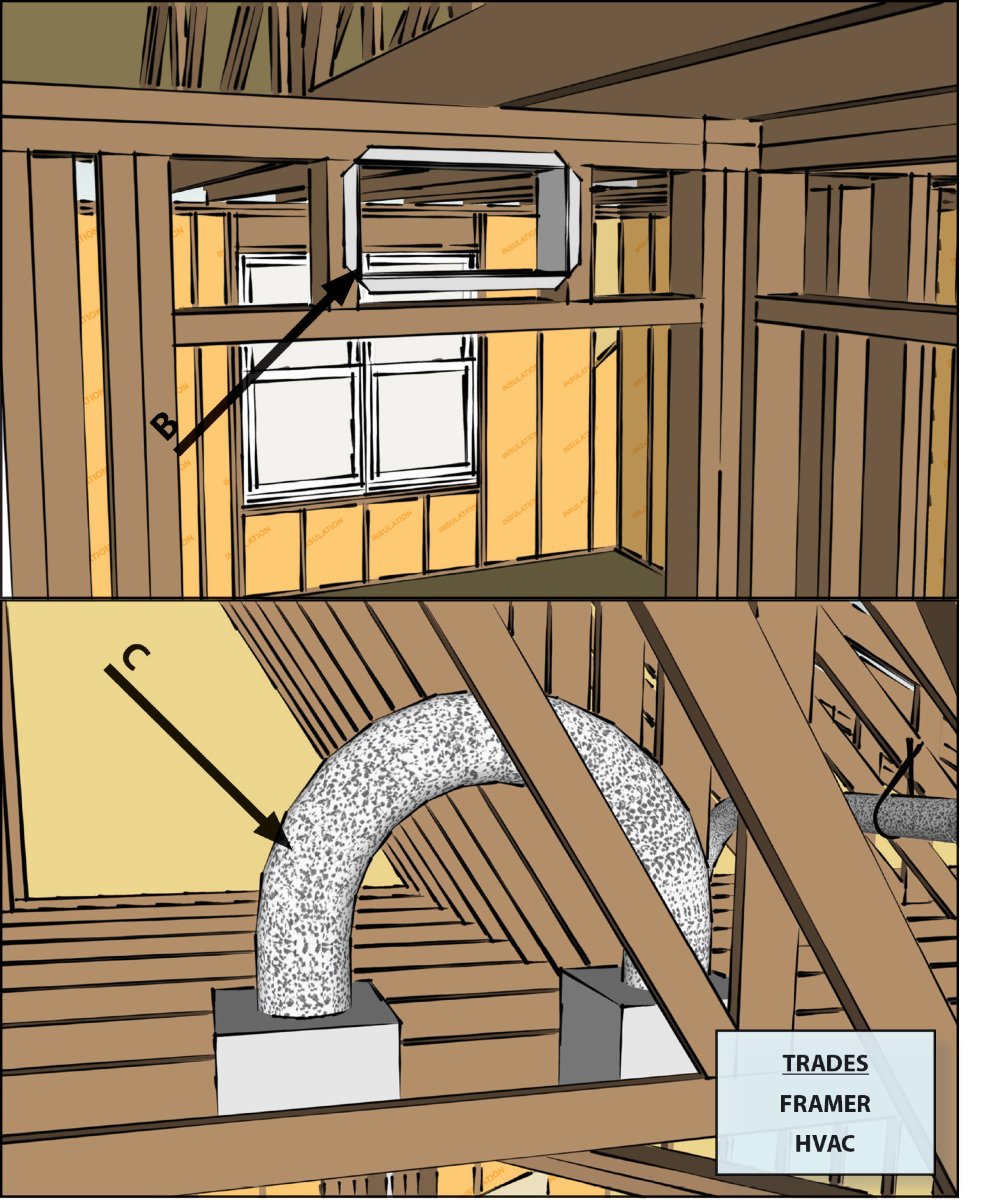
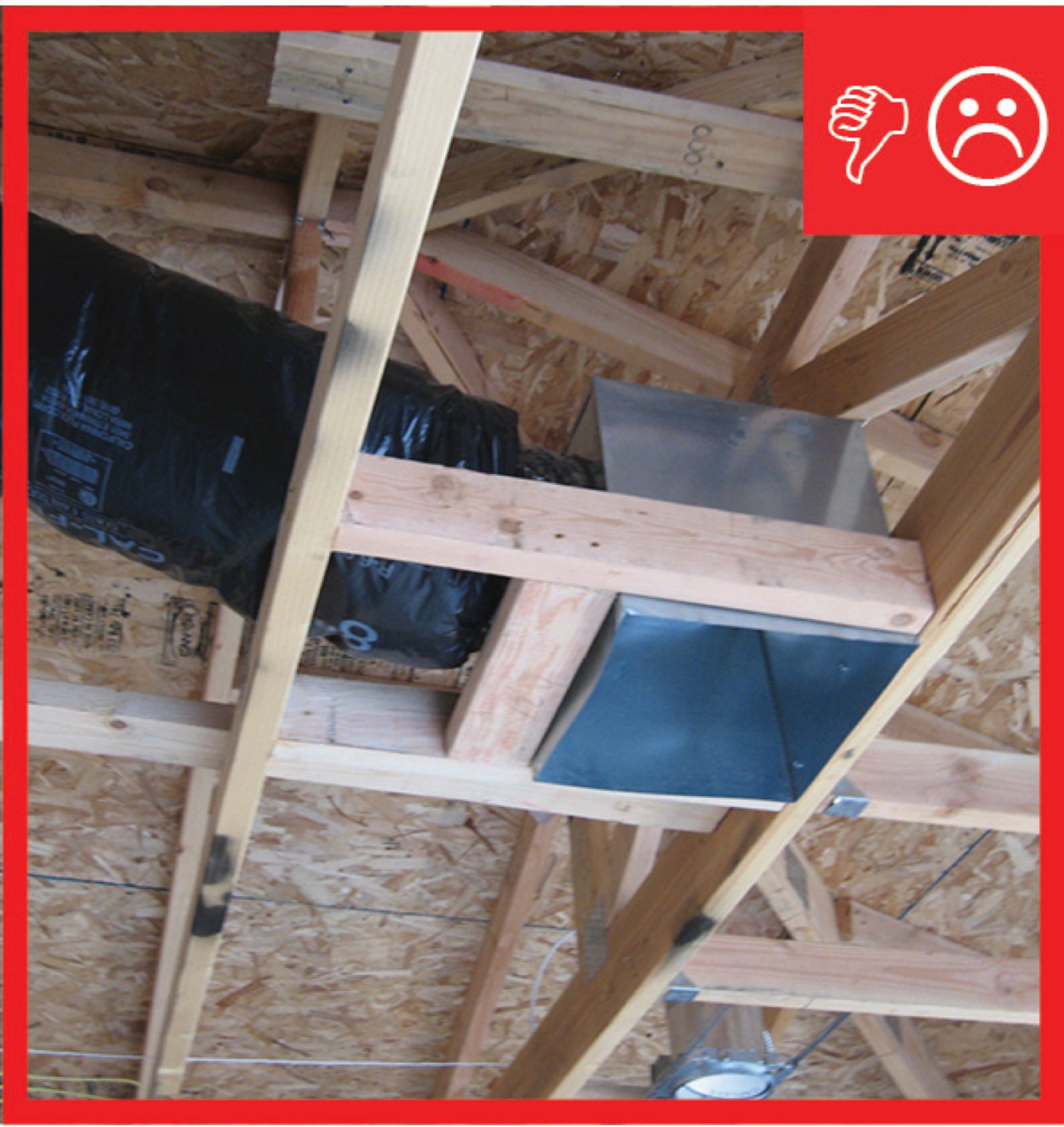
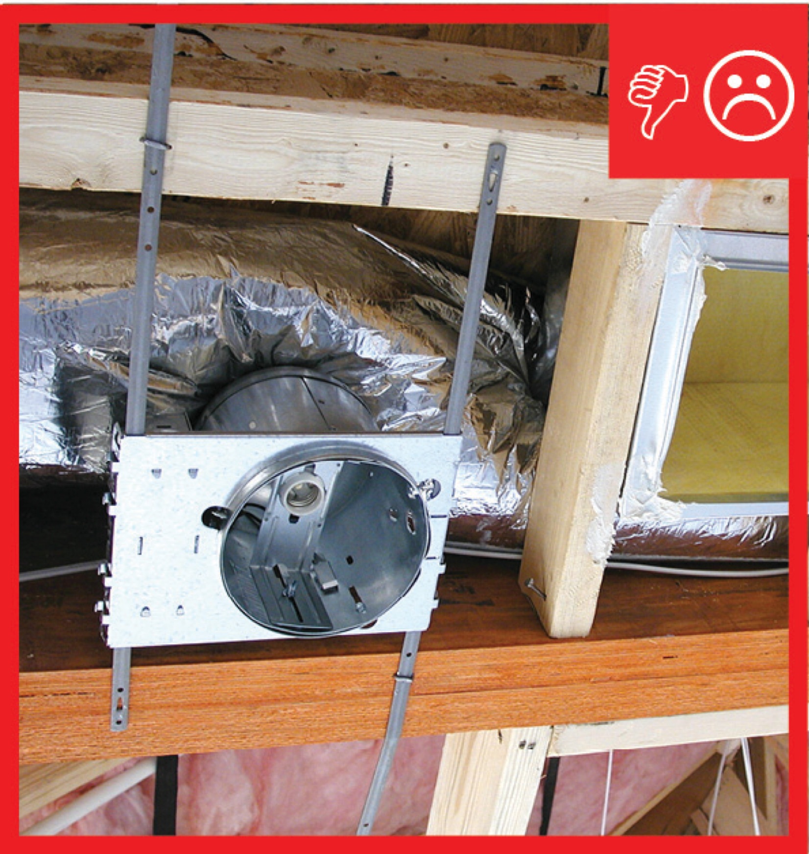
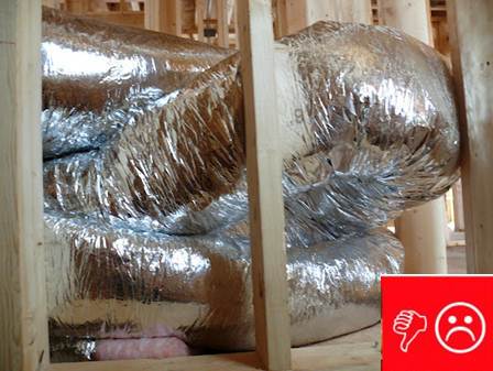
Flexible ducts in unconditioned space not installed in cavities smaller than outer duct diameter; in conditioned space not installed in cavities smaller than inner duct diameter
Image
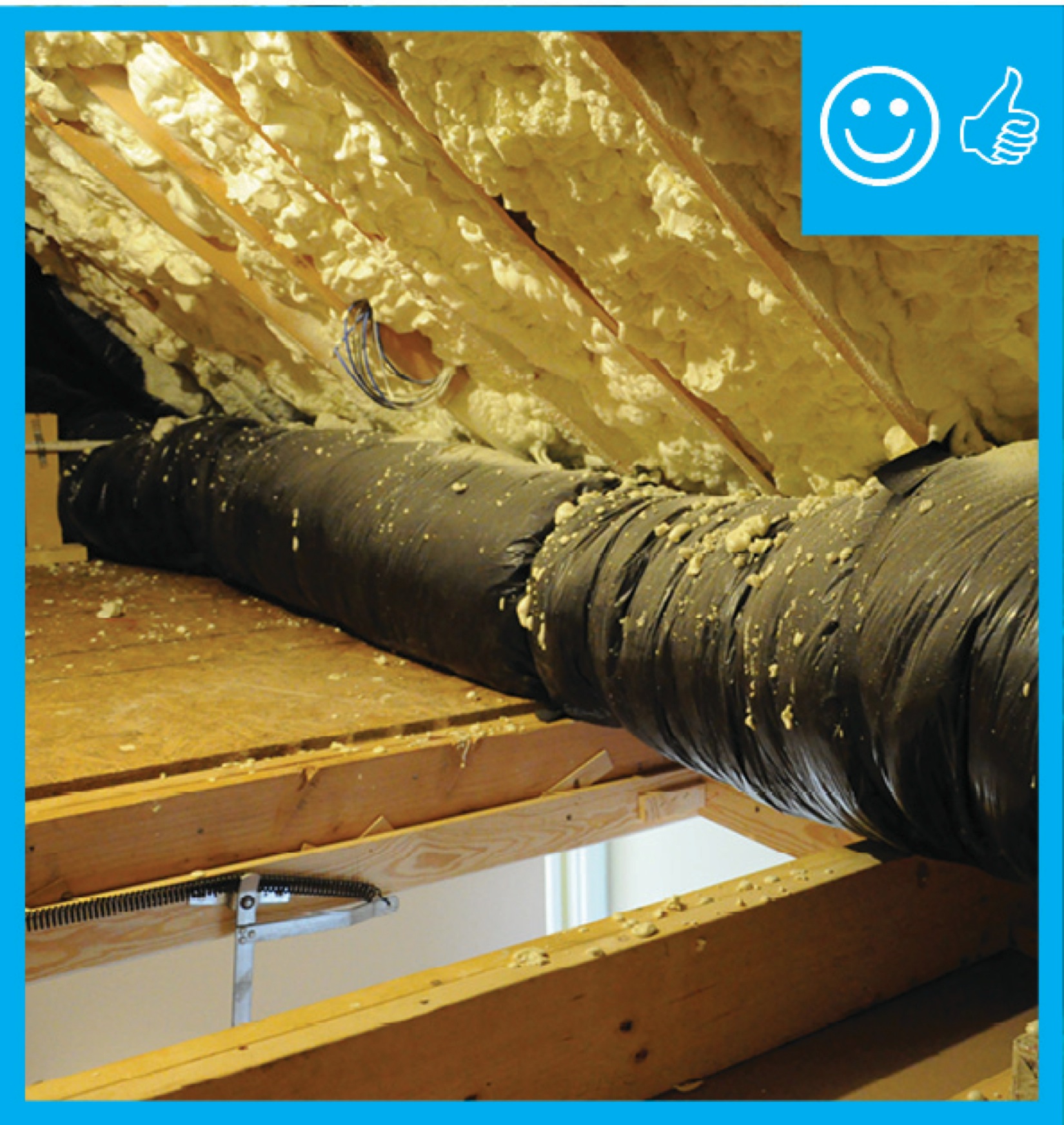
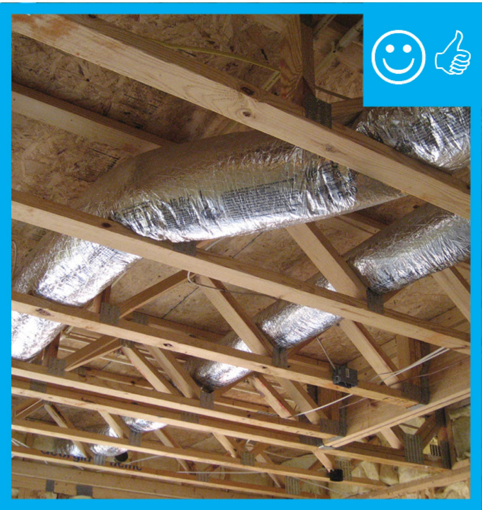
Flexible ducts supported at intervals as recommended by mfr. but at a distance ≤ 5 ft
Image
Image
Image
Image
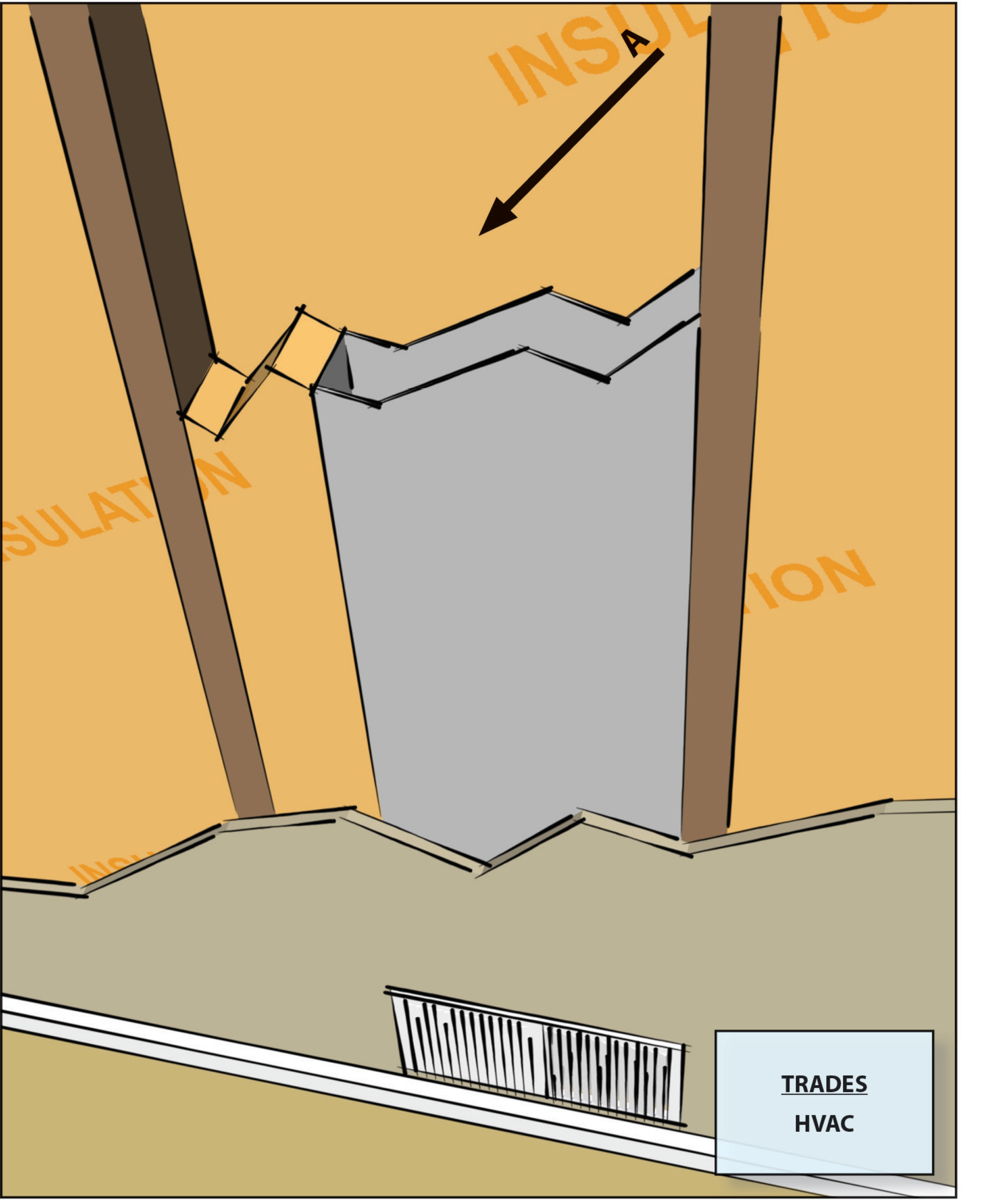
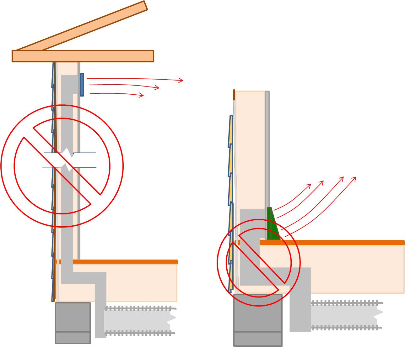
HVAC ducts, cavities used as ducts, and combustion inlets and outlets may pass perpendicularly through exterior walls but shall not be run within exterior walls unless at least R-6 continuous insulation is provided on exterior side of the cavity
Image
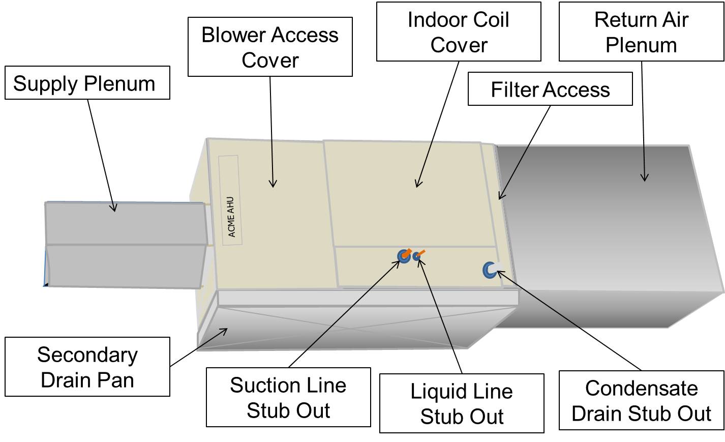
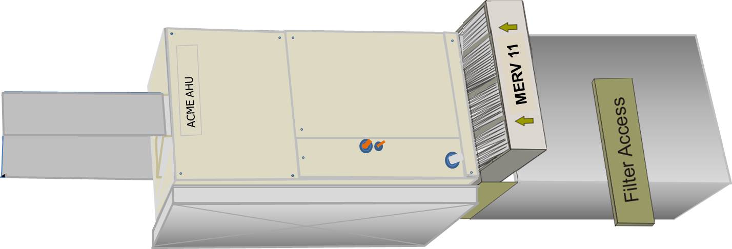
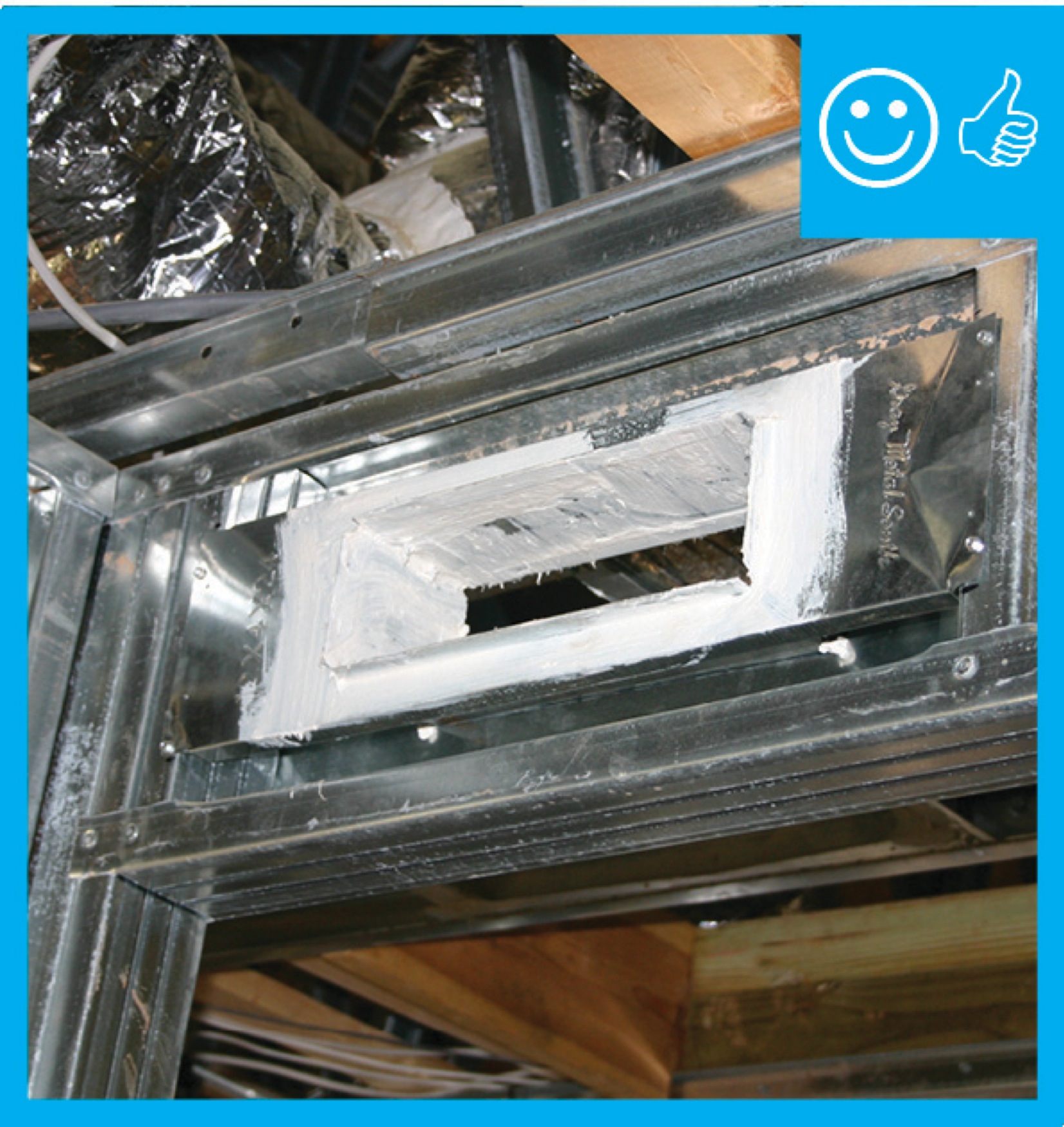
If filter is inaccessible, locate the air filter between the return air plenum and the air handler box
Image

If furnace is accessible, locate the air filter between the return air plenum and the air handler box
Image
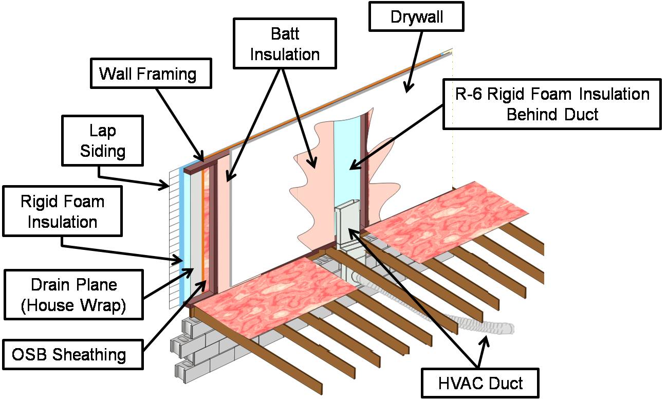
If HVAC duct must be installed in an exterior wall, separate it from the exterior with at least R-6 of continuous rigid insulation
Image

If the furnace is hard to access, locate filters at return registers covered by hinged grilles that are easy to open from inside the home
Image
Image
Inadequate amount of insulation installed with compression, misalignment, and voids
Image
Image
Image
Image
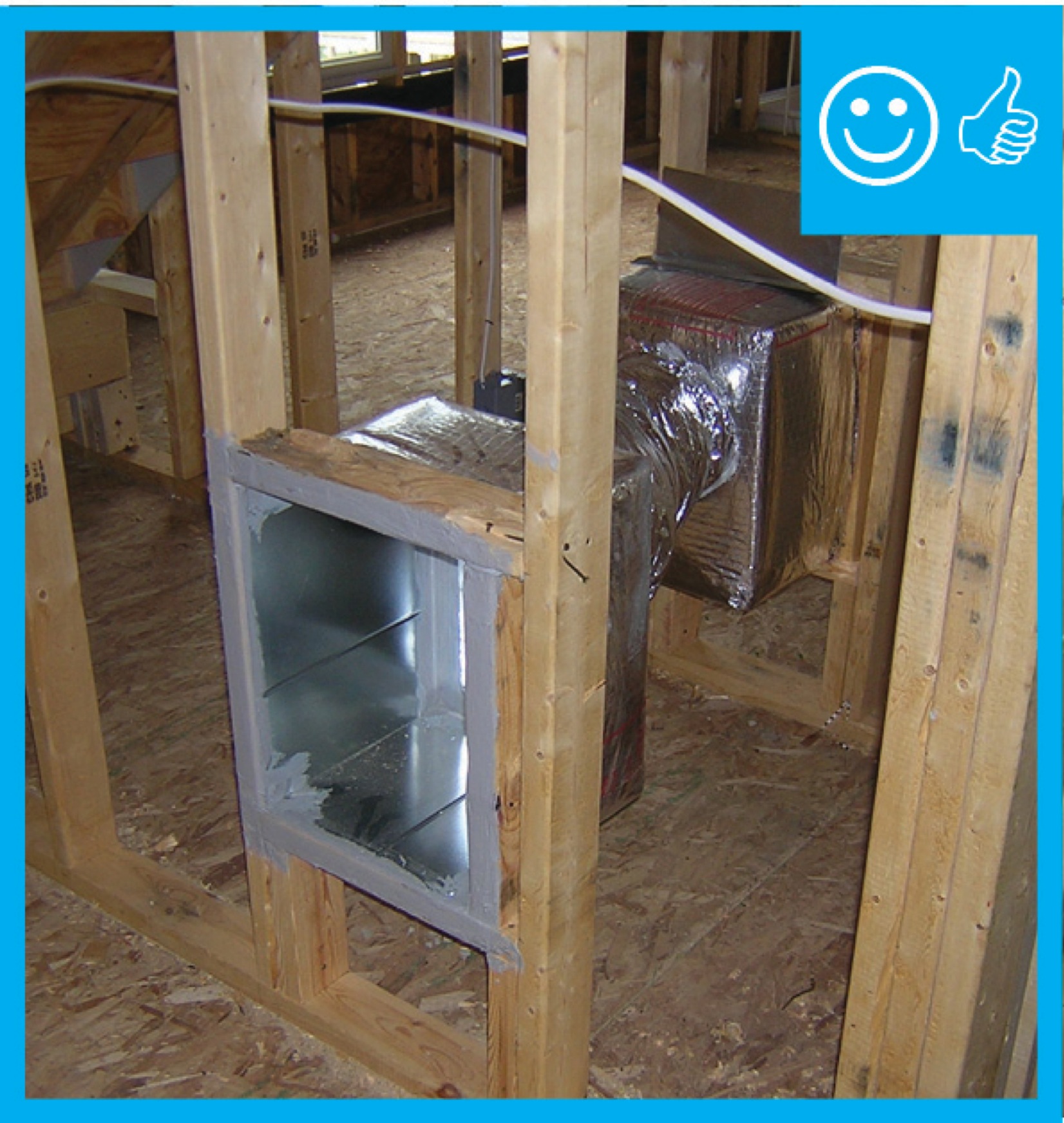
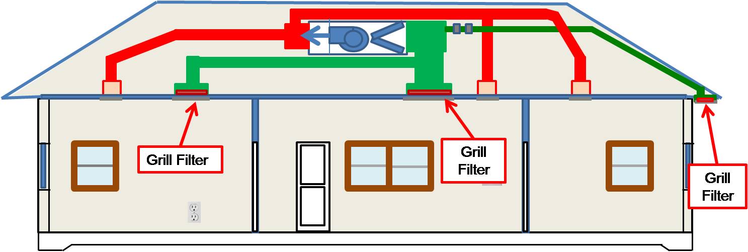
Install supply registers in floors or ceilings to avoid routing ducts through exterior walls
Image
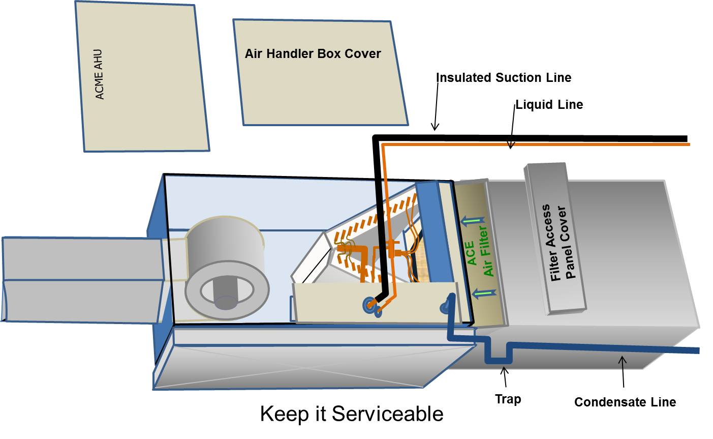
Install the filter media box between the return air plenum and the air handler box
Image
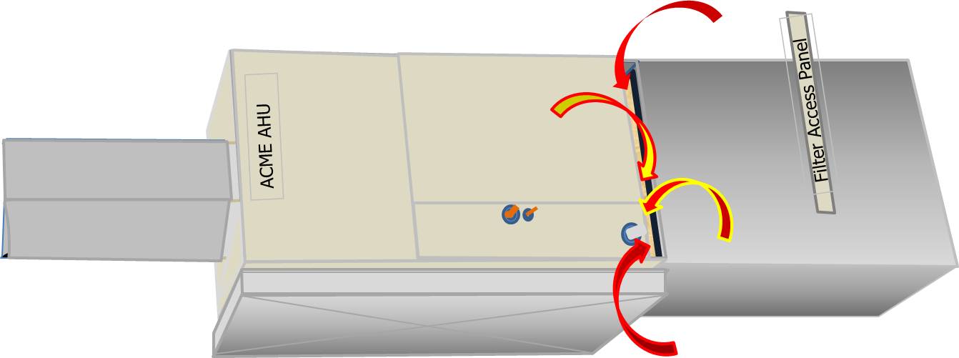
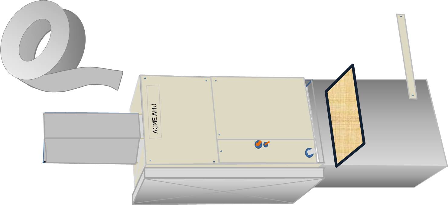
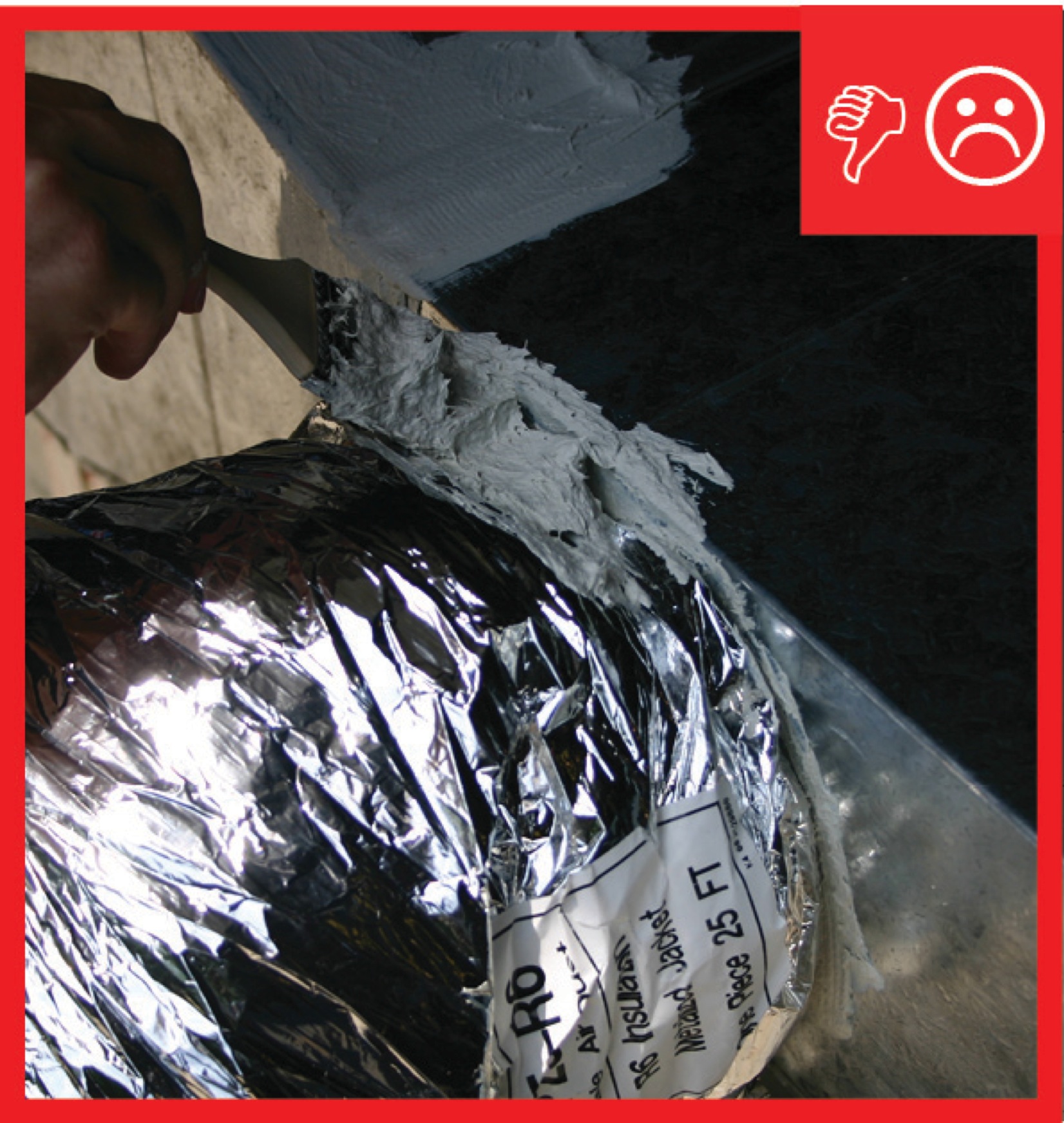
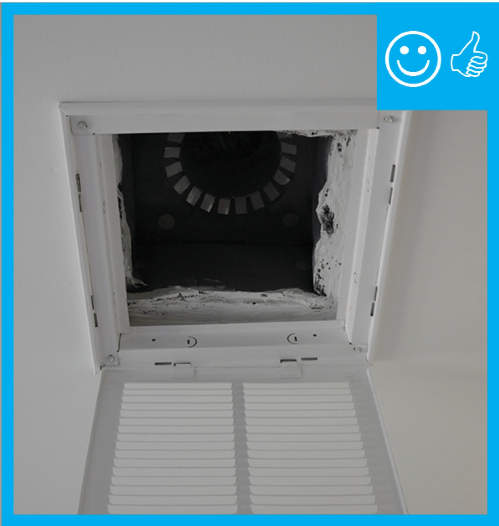
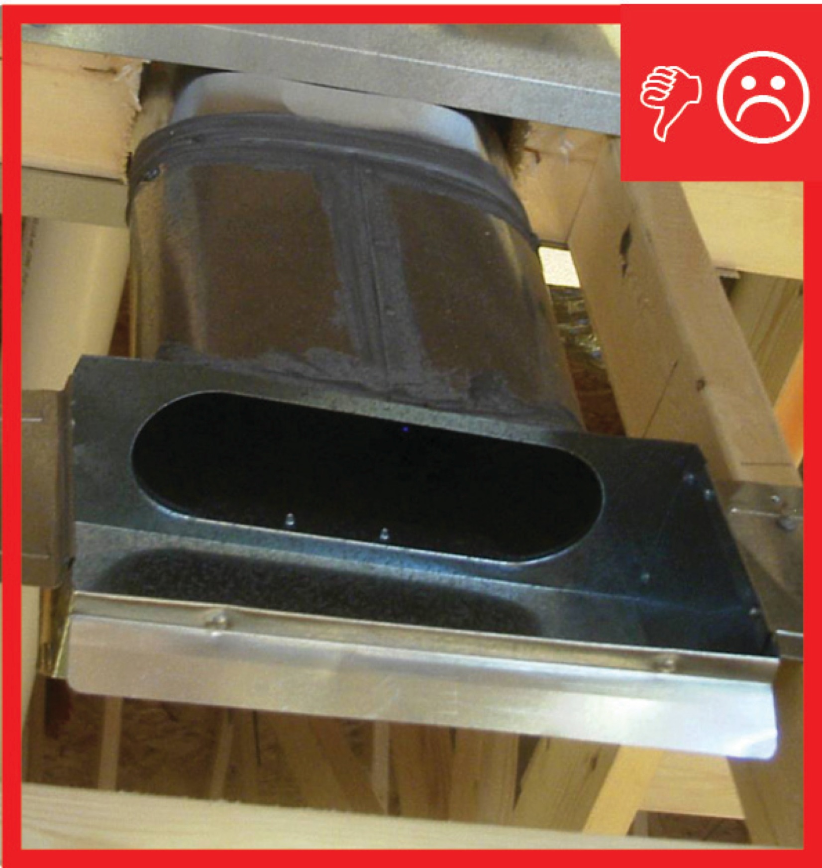
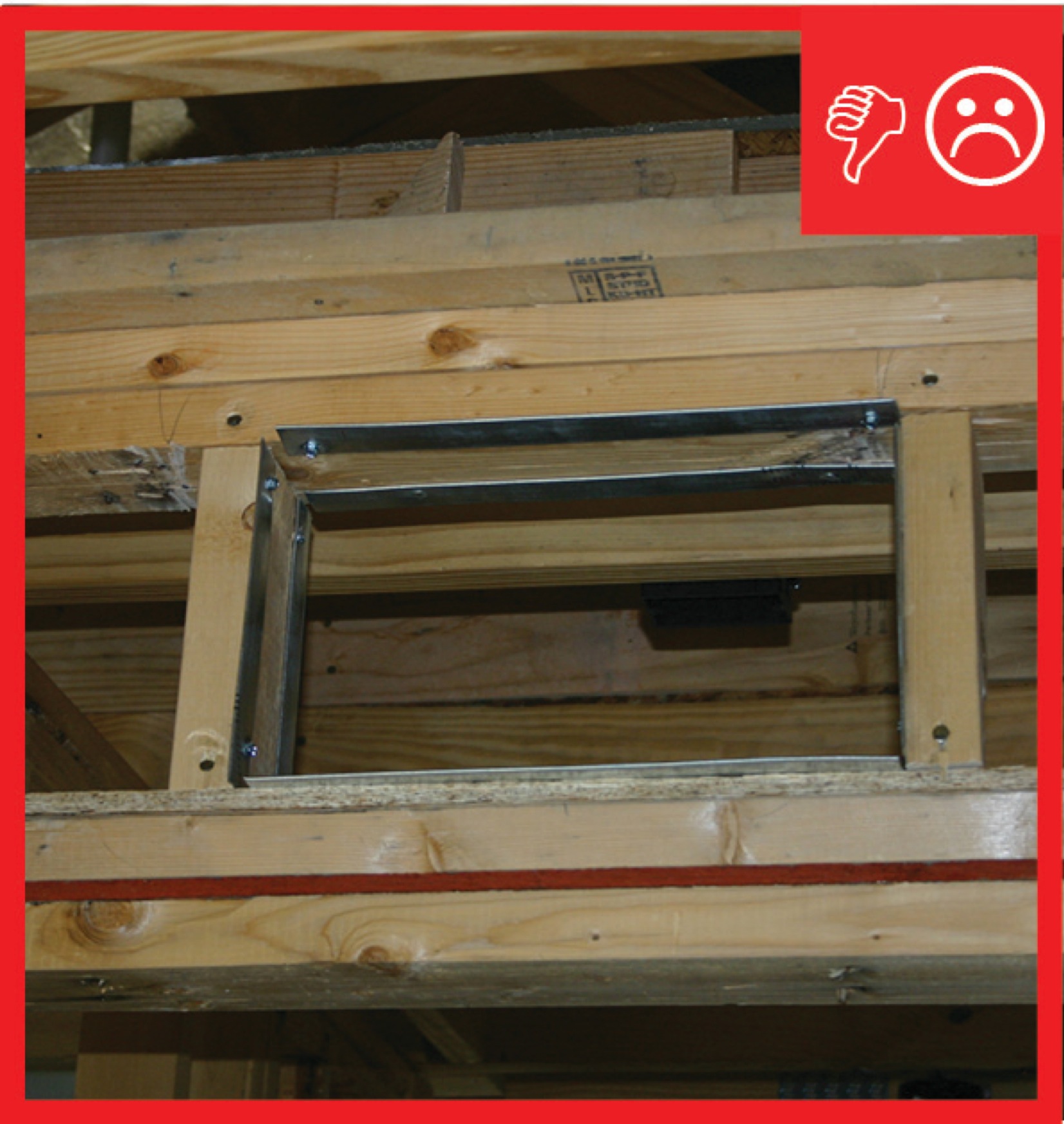
Leaks at the air filter cover panel can draw in unconditioned or undesirable air
Image
Locate the fresh air intake away from pollution sources and in an easily accessible location
Image
Image
Image
Image
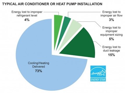
Most residential heat pumps are installed incorrectly and with energy-wasting faults.
Image
Image
Image
Image
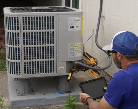
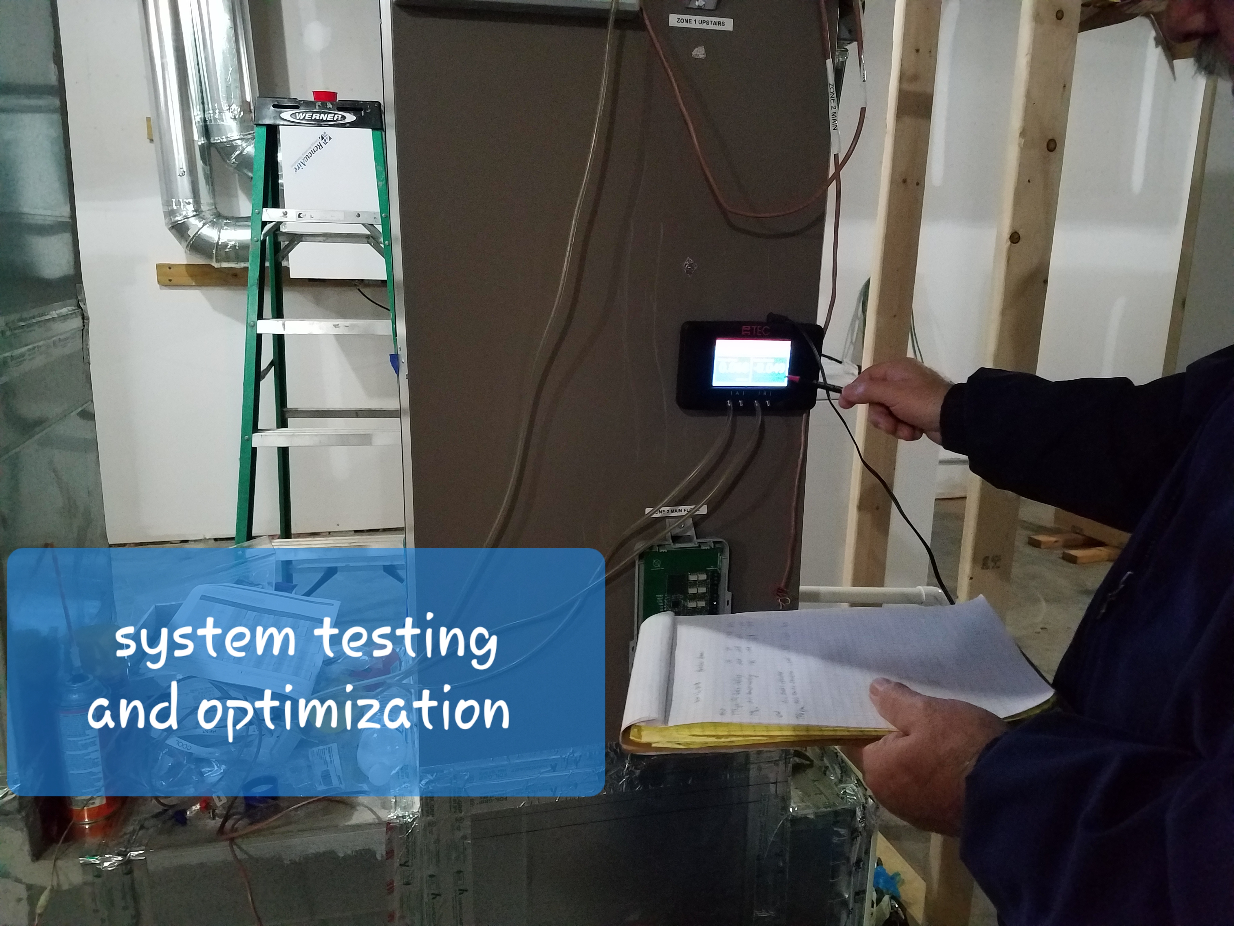
Quality installation and commissioning are critical to optimizing heat pump performance.
Image
Image
Image
Image
Image
Image
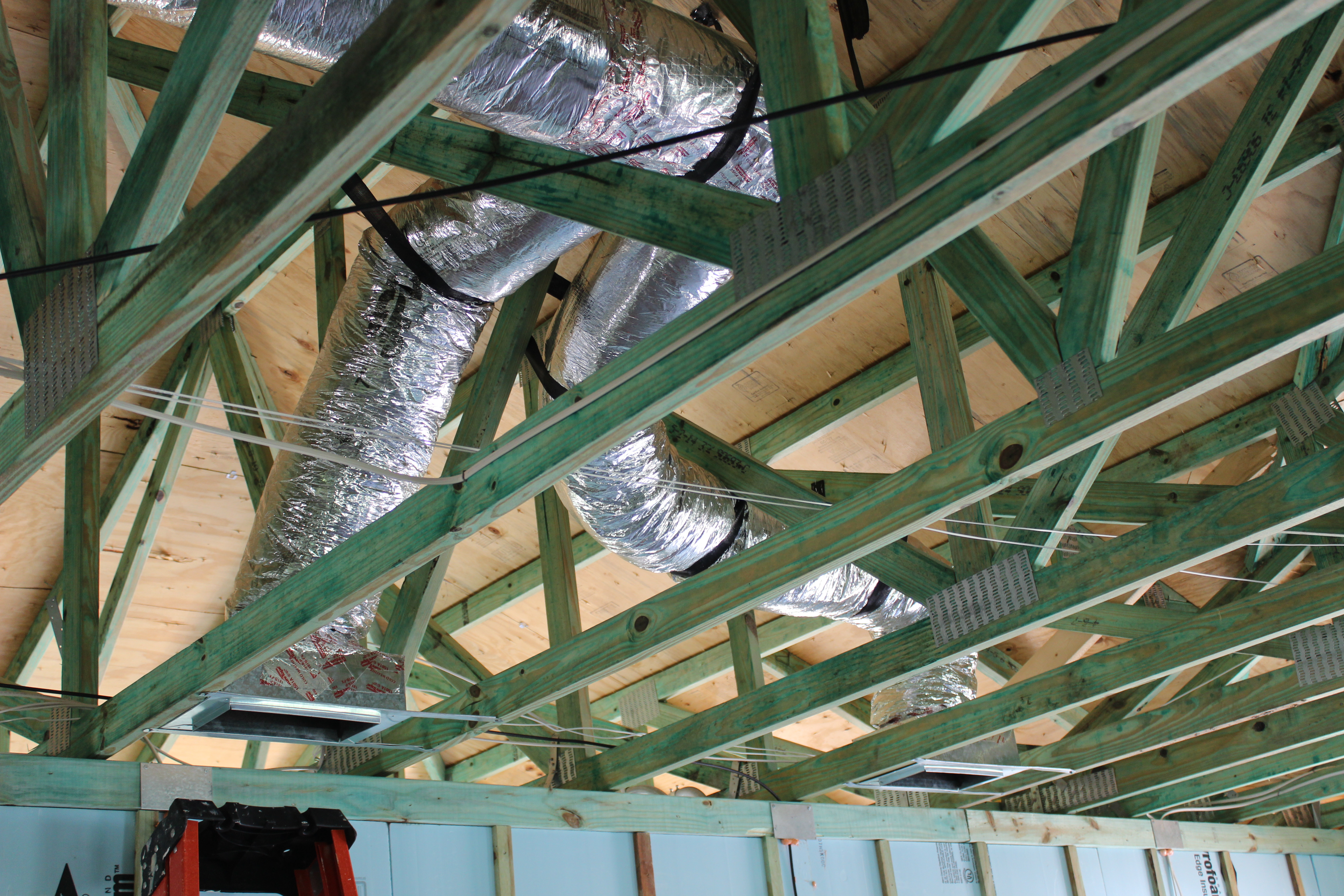
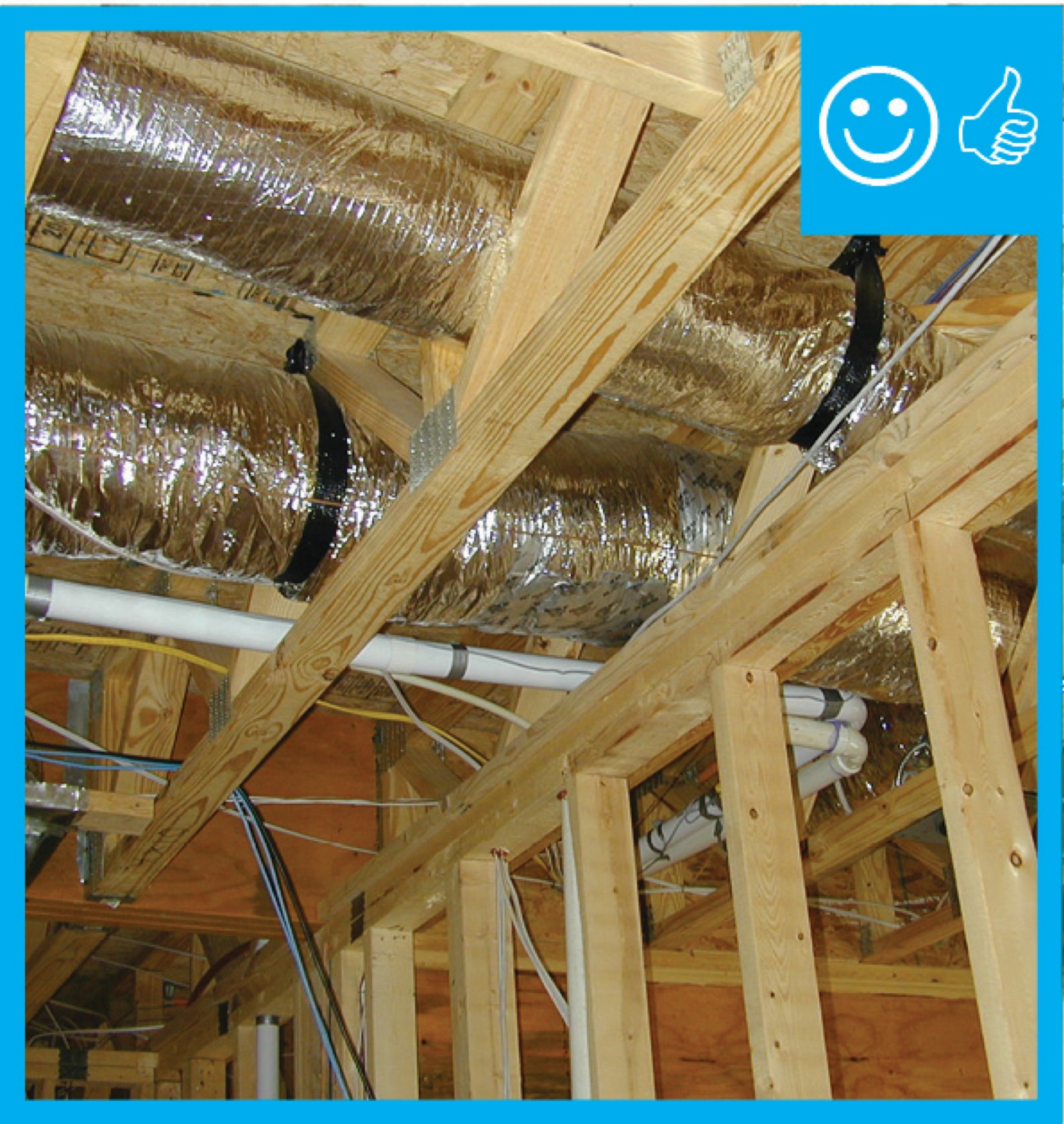
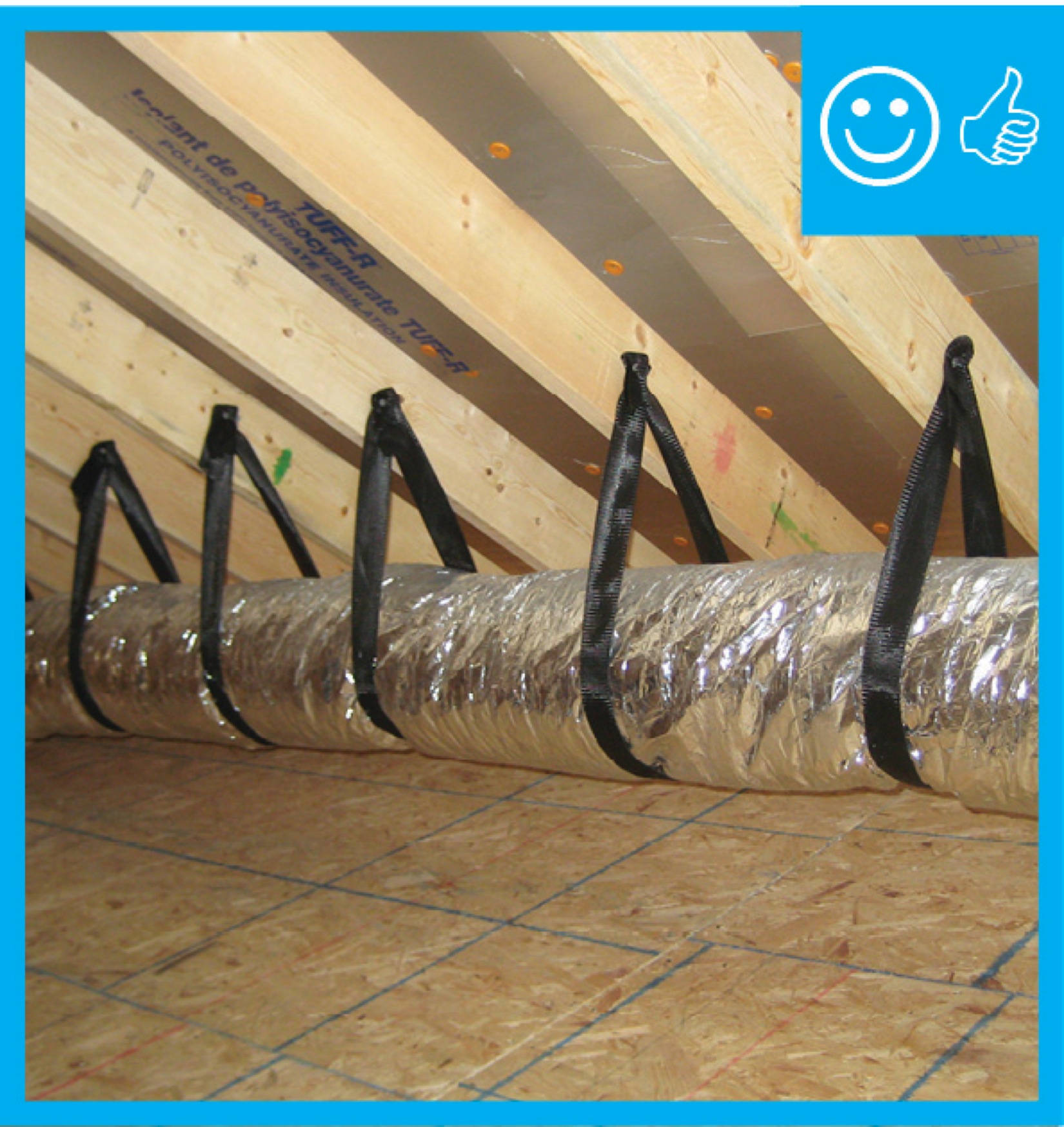
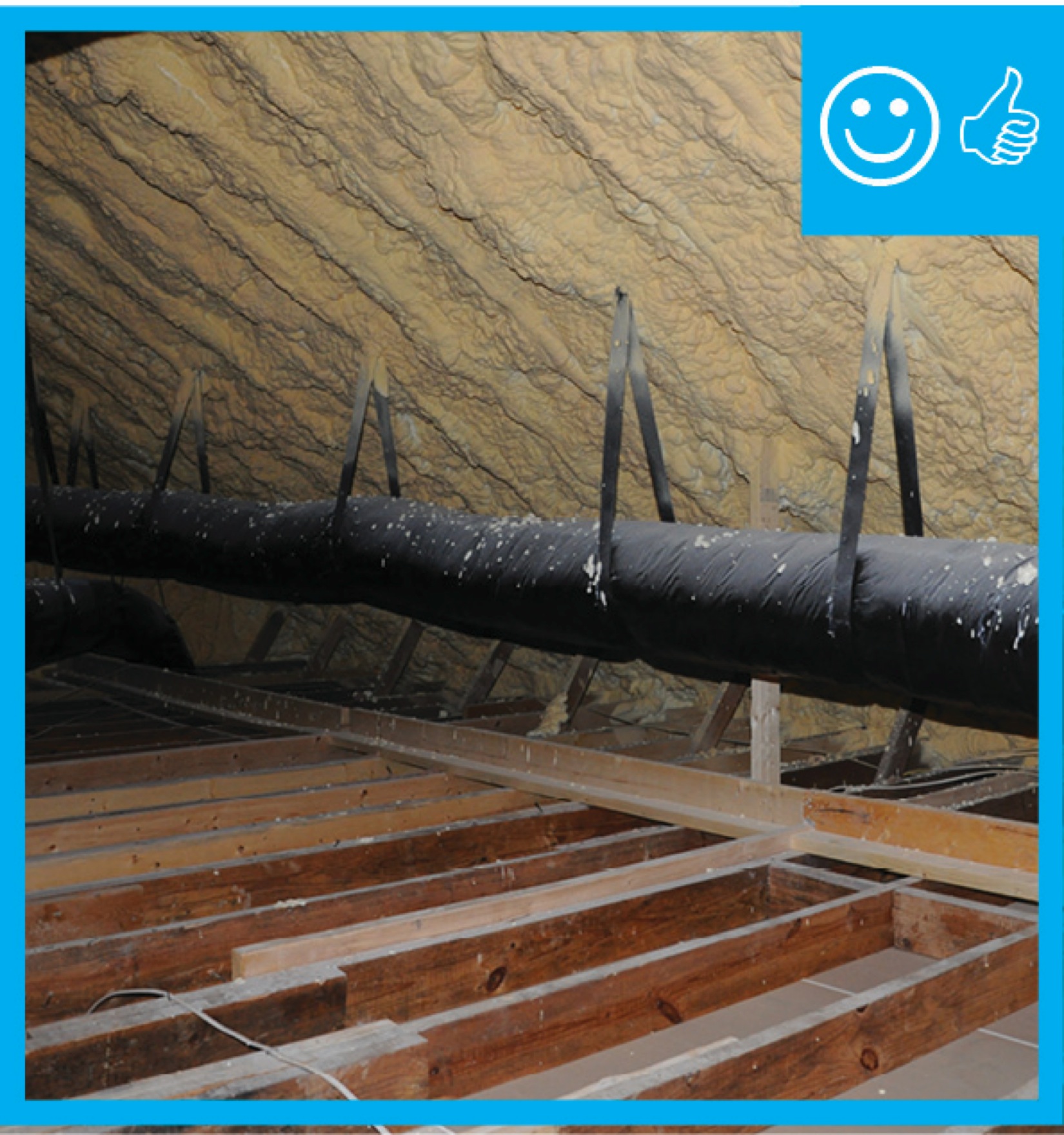
Right – Flex ducts are properly supported with straps that don’t pinch the insulation; closed-cell spray foam will be applied to the underside of the roof deck of this hot-humid climate home to provide an insulated attic space for the HVAC ducts.
Image
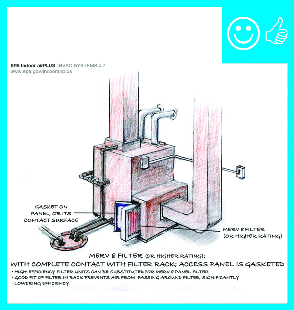
Right – HVAC furnace filter is properly installed in cabinet with gasketed cover to prevent air leakage
Image
Image
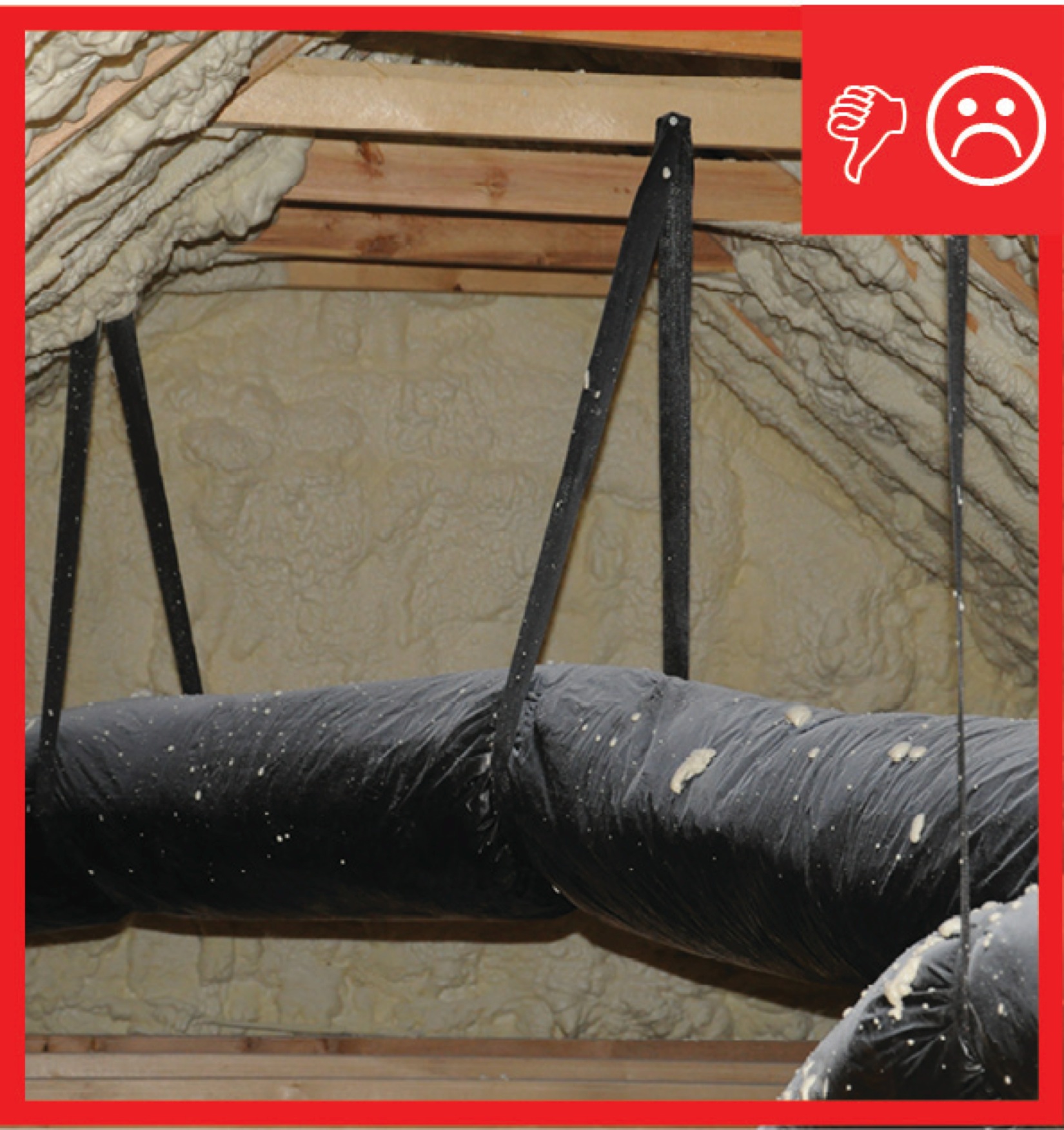
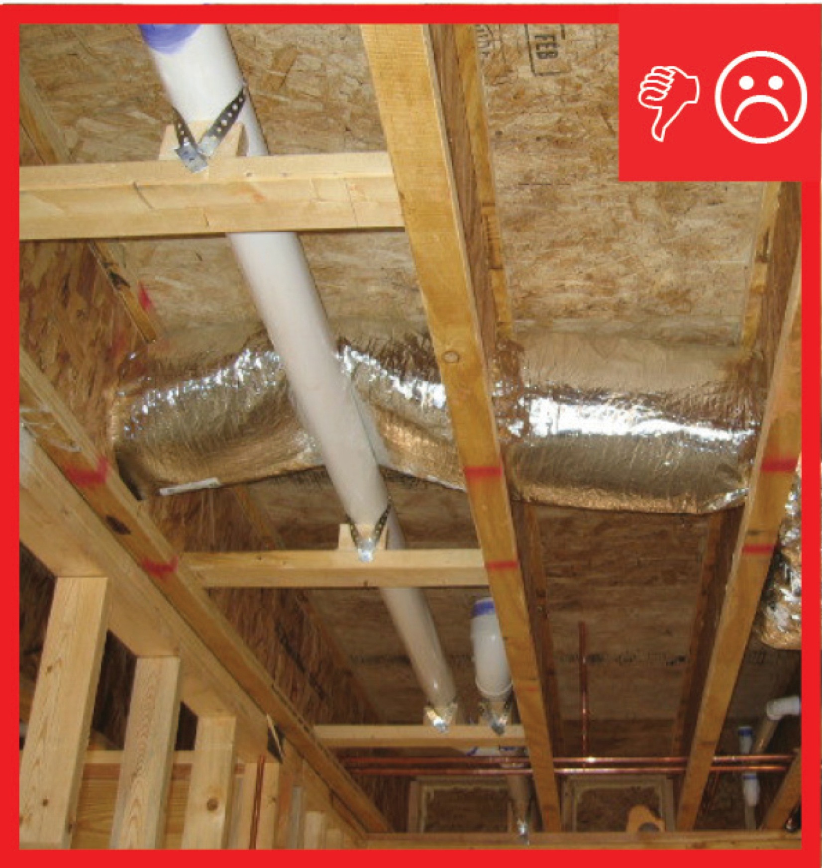
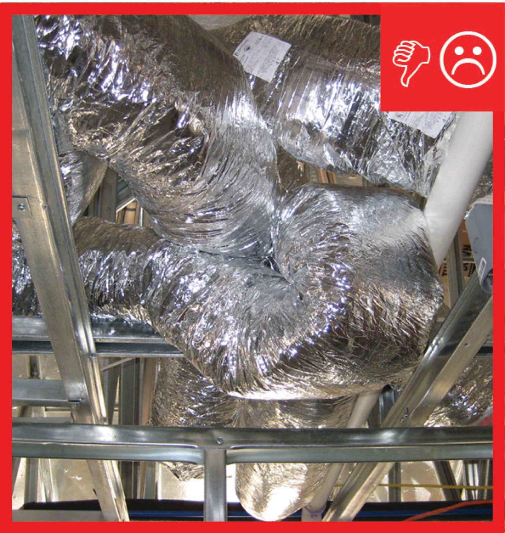
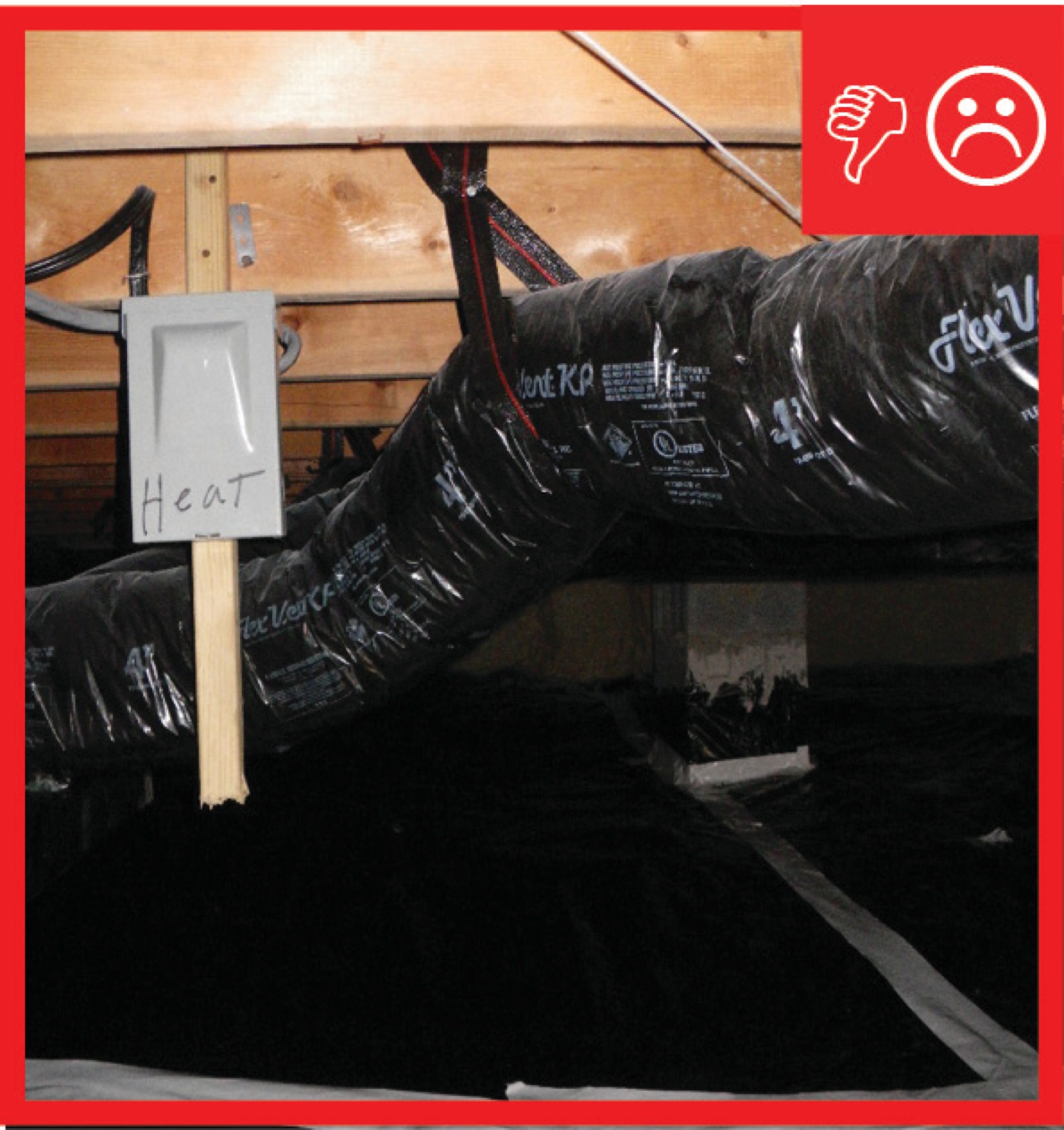
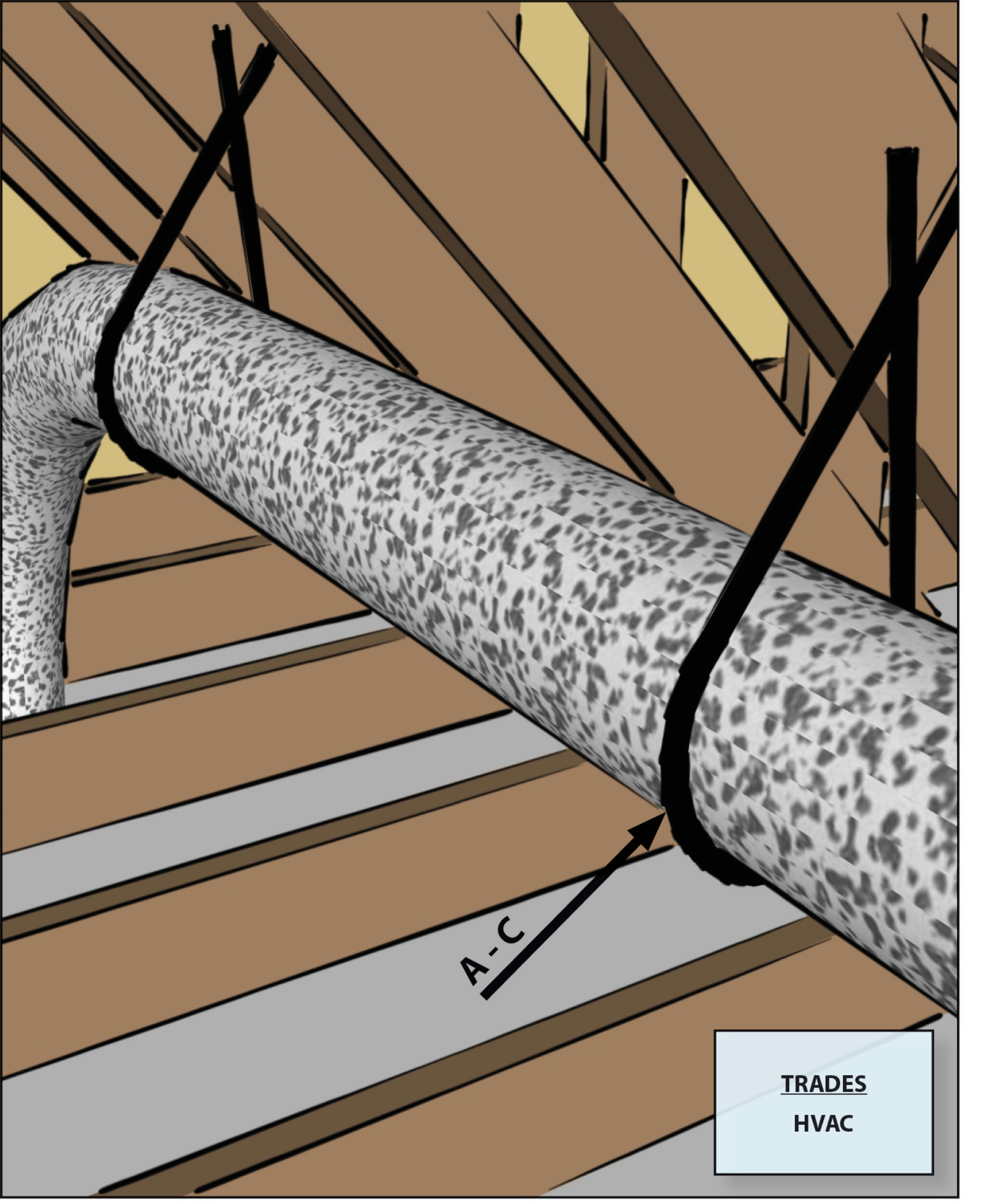
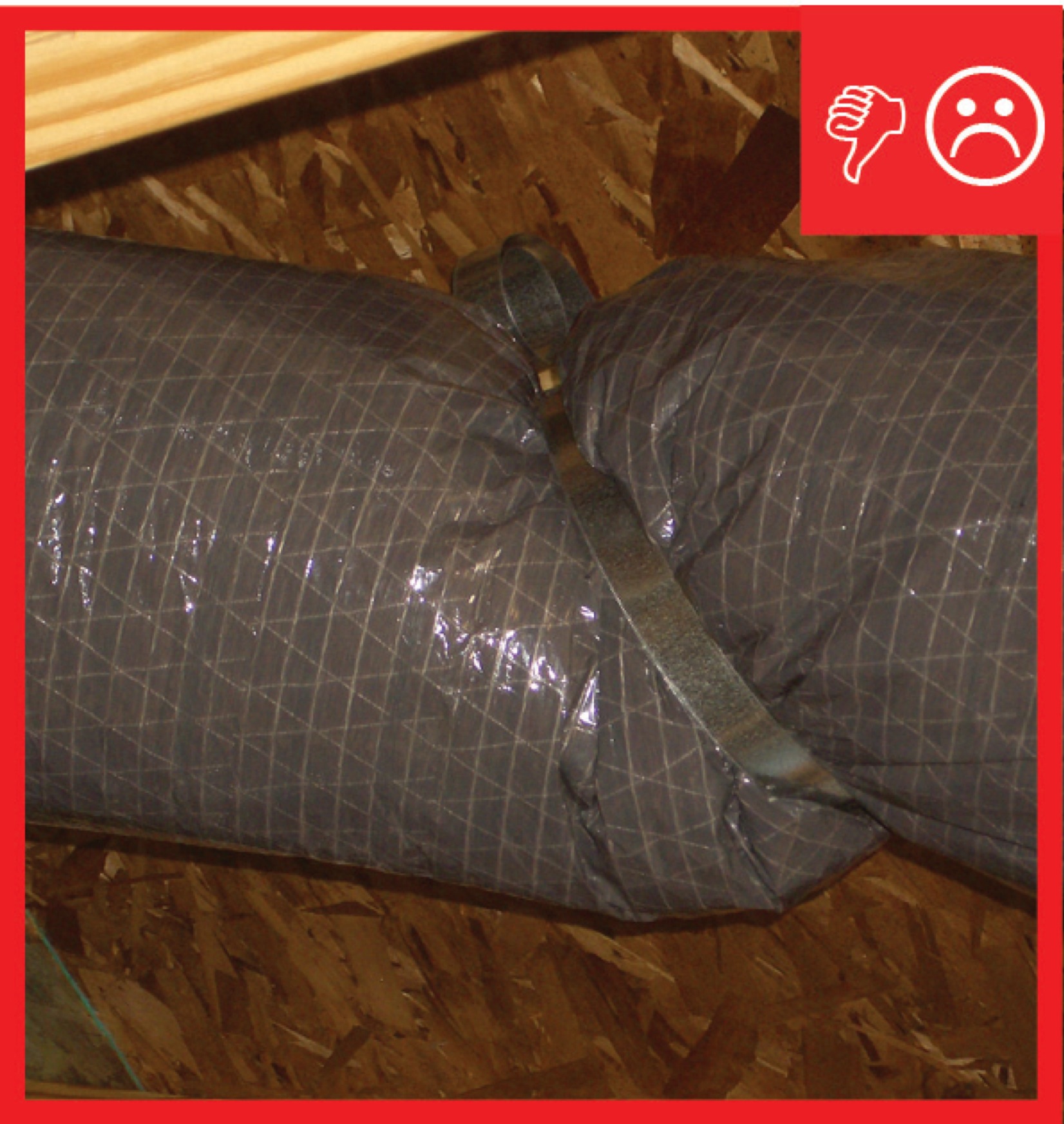
Straps are spaced too far apart causing the straps to compress the duct under its own weight
Image
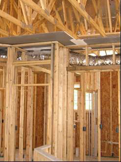
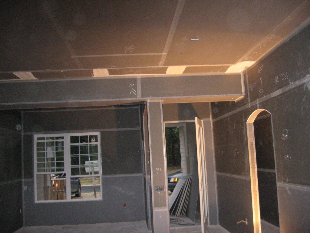
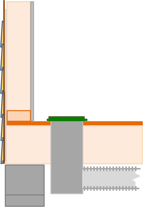
The drywall above the dropped ceiling duct chase extends beyond adjoining top plates for a continuous air barrier
Image
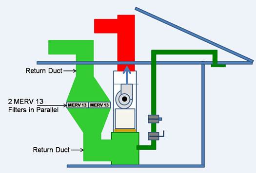
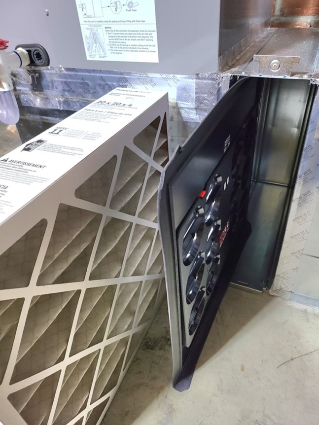
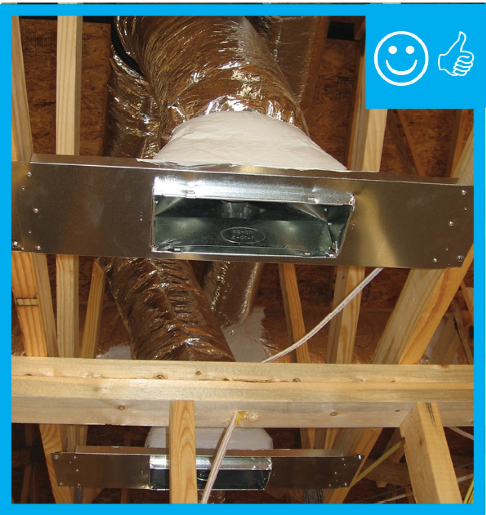
To increase surface area and reduce pressure drop for high MERV filters, the return duct can be constructed to permit the installation of two furnace filters side by side
Image
Image
Image
Image
Image
Image
Image
Image