Showing results 51 - 100 of 125
Image
Image

Image
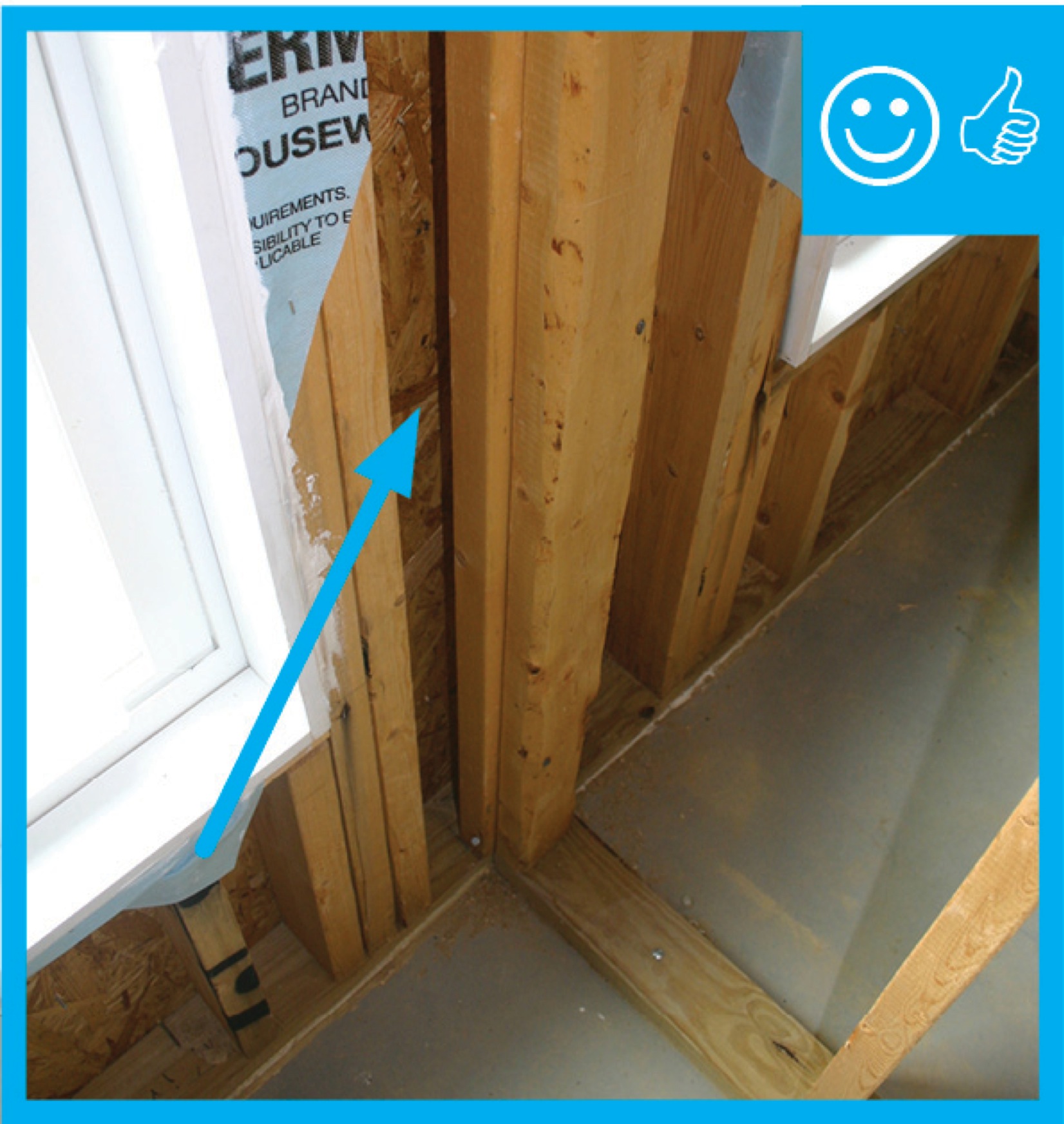
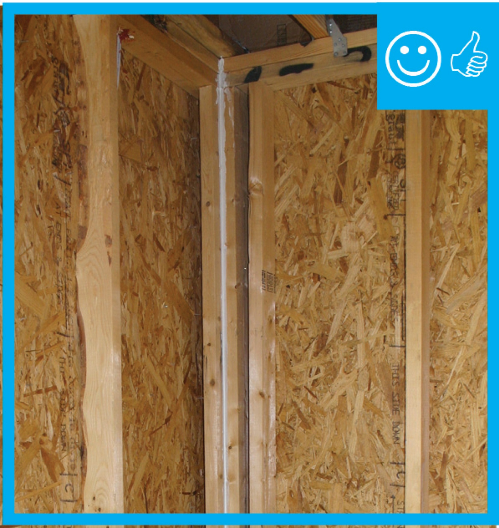
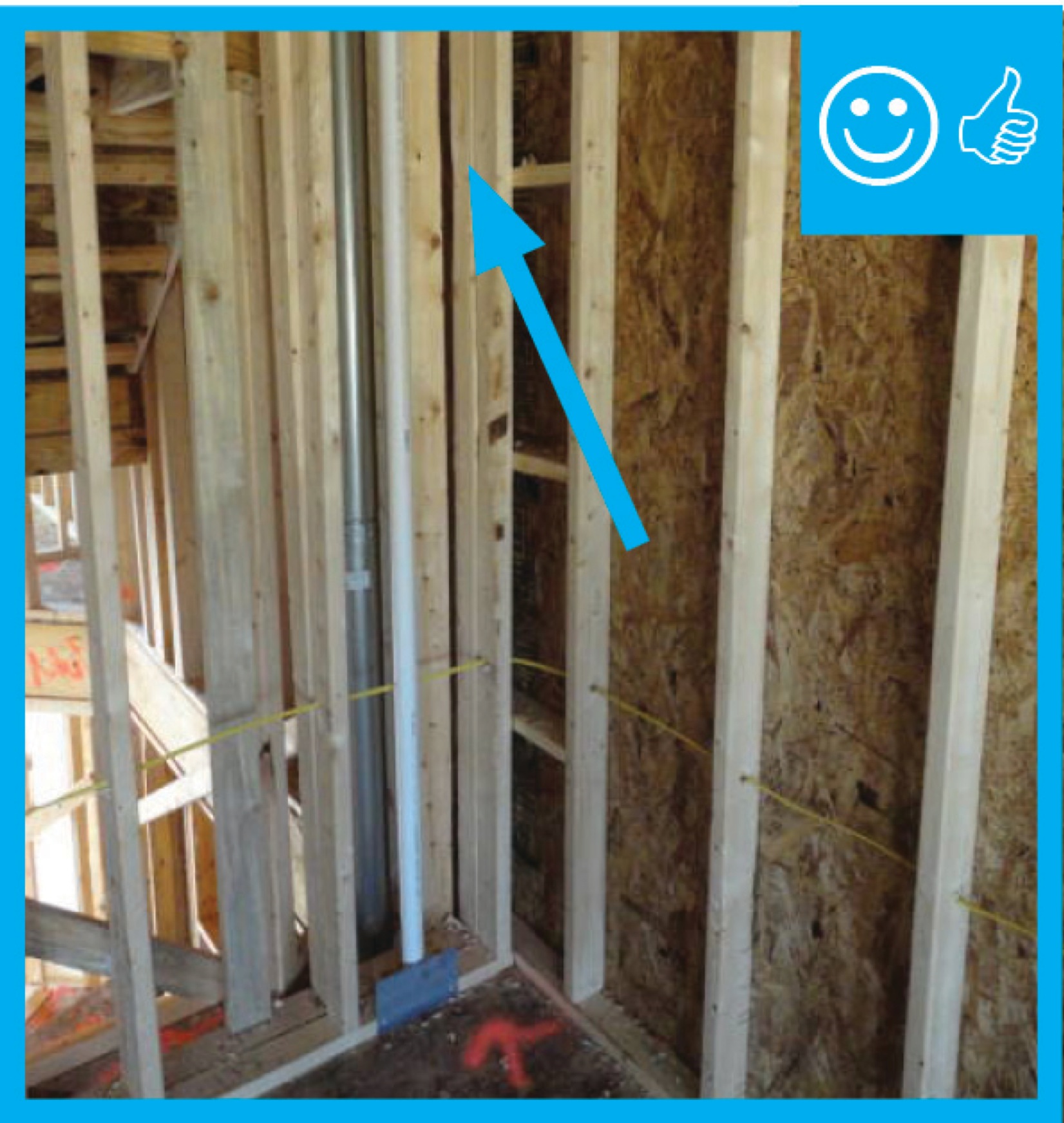
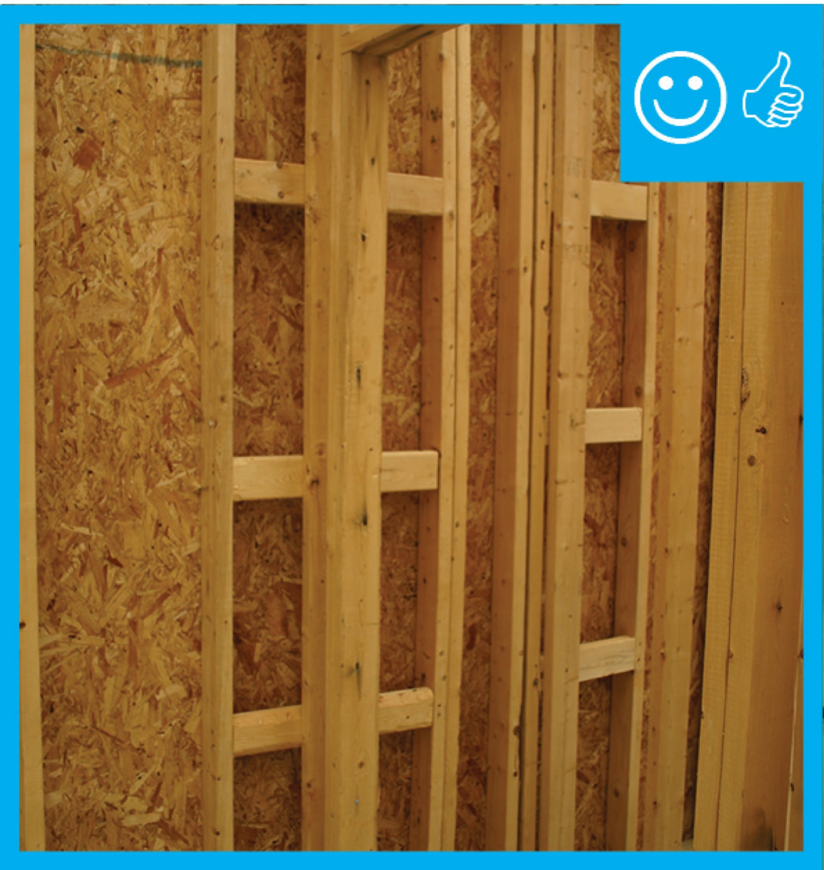
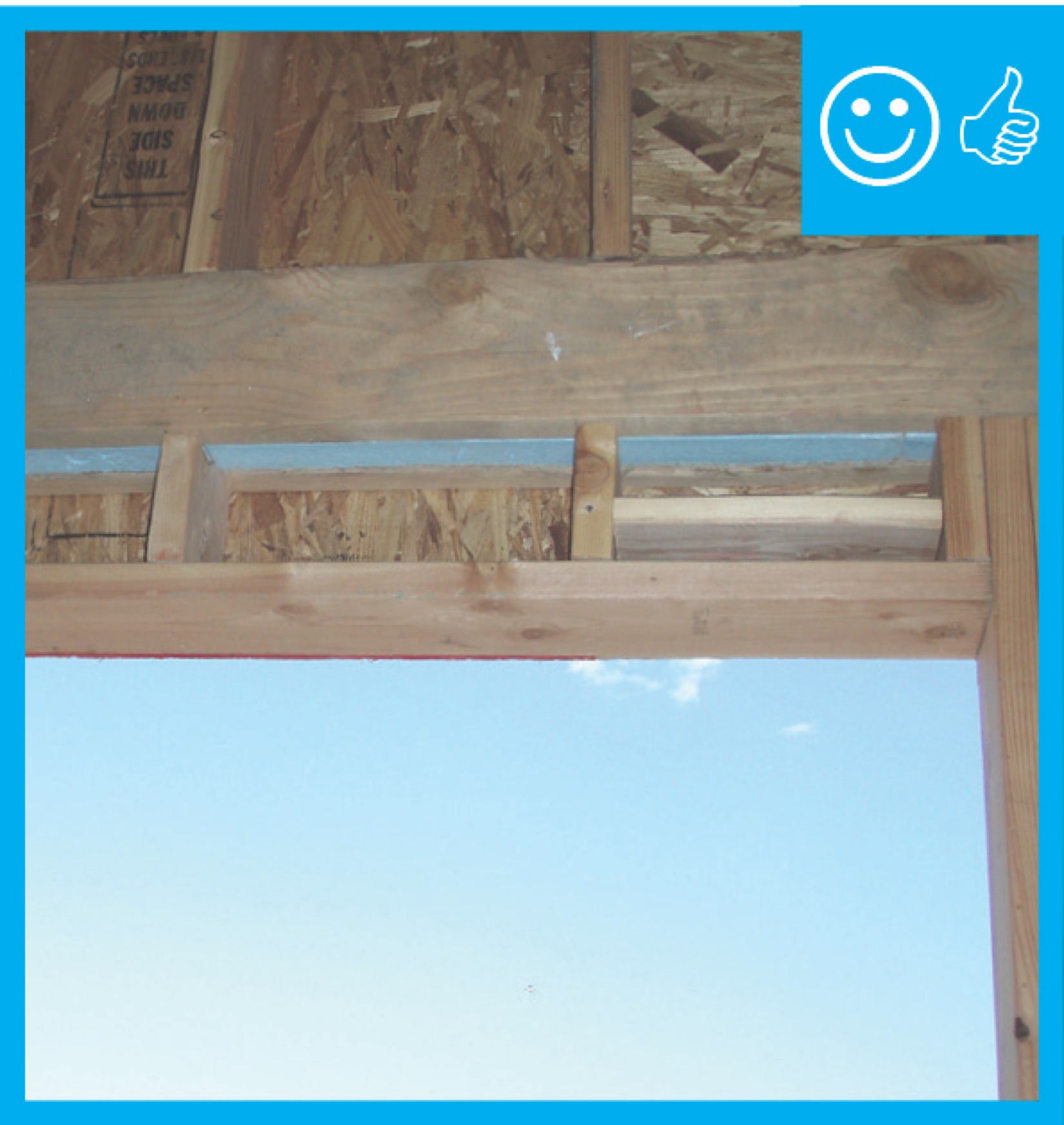
Right – Full length 2x6 nailer has been installed to allow space for insulation at wall intersection
Image
Image
Image
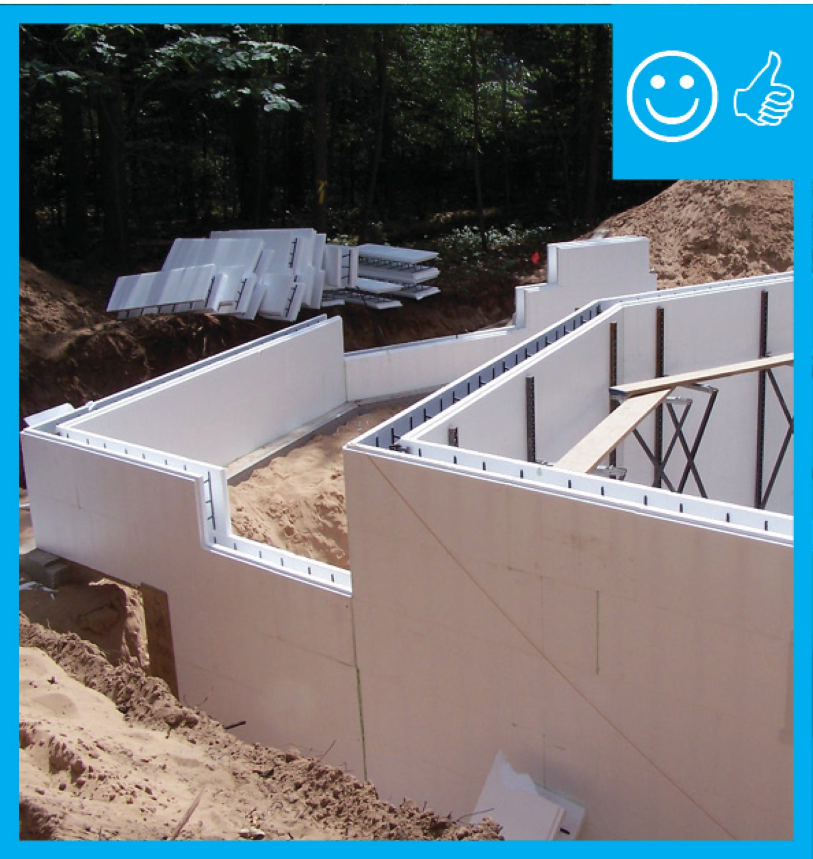
Right – ICFs are being installed to create a continuous air and thermal boundary
Image
Right – ICFs are being installed to create a continuous air and thermal boundary
Image

Right – ICFs are being installed to create a continuous air and thermal boundary
Image

Right – ICFs are being installed to create a continuous air and thermal boundary
Image
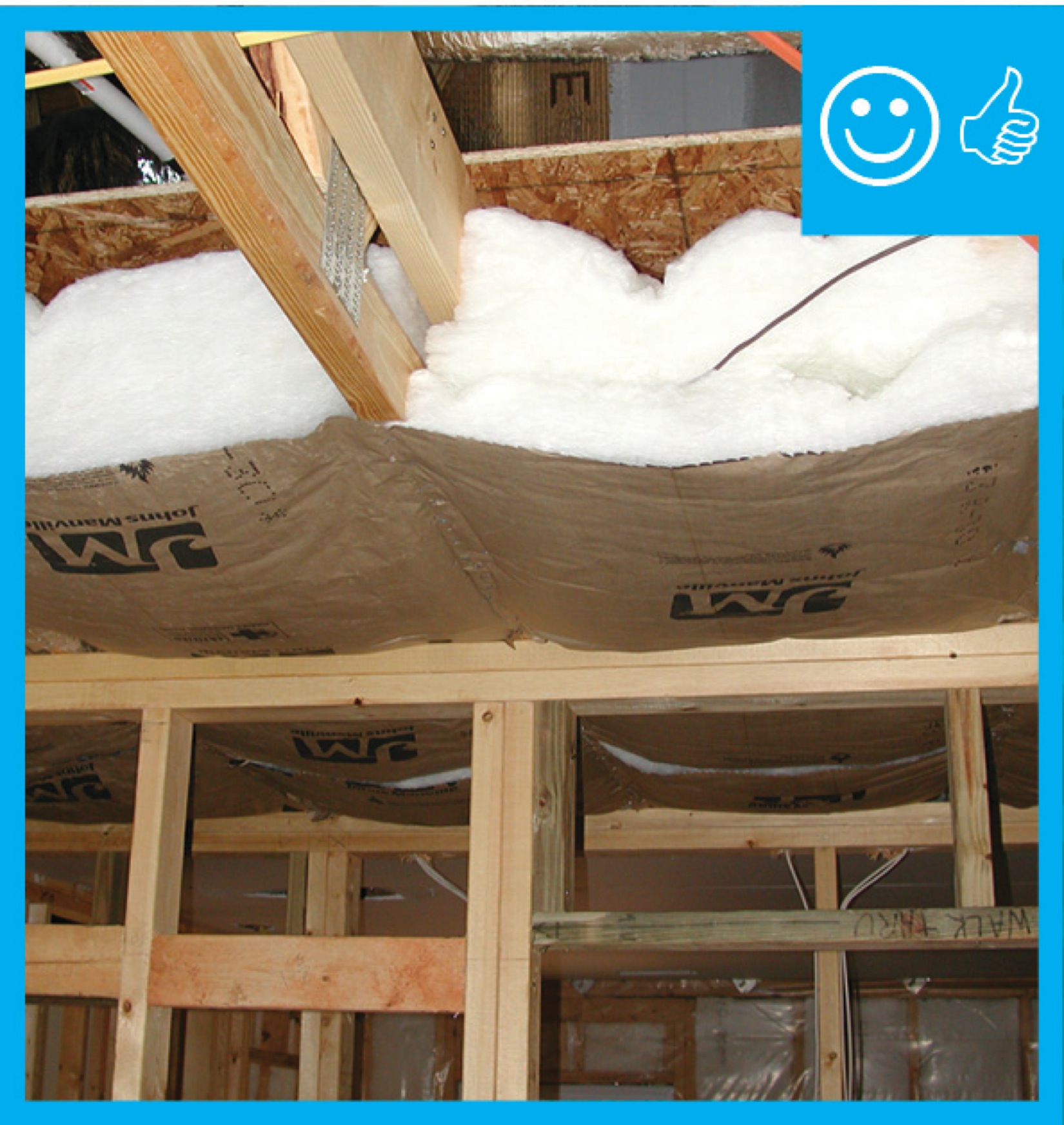
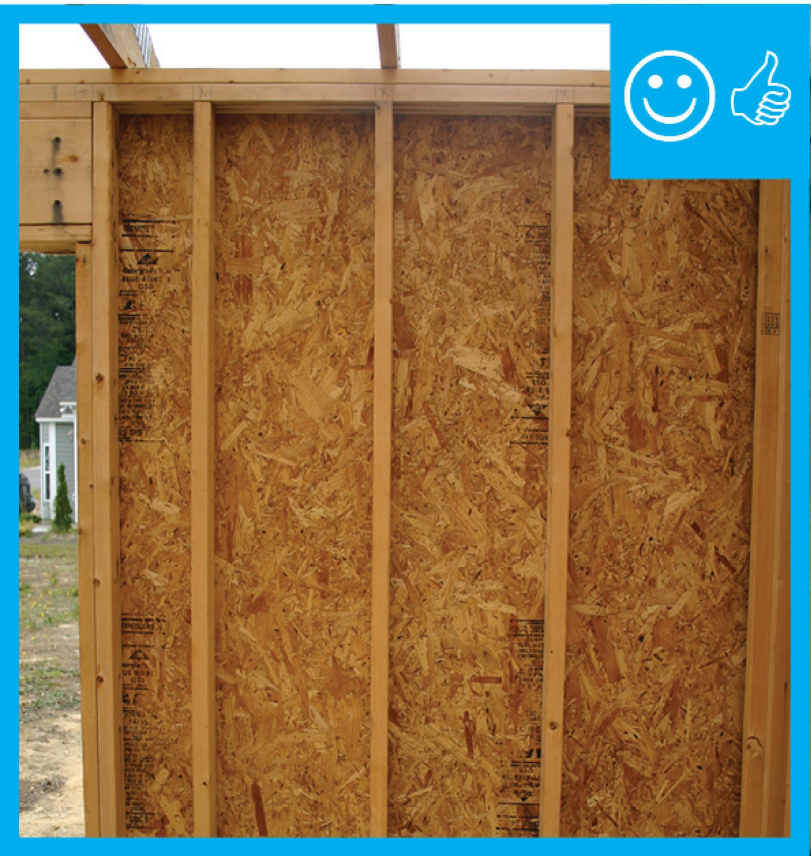
Right – Insulation installed to correct depth and will be aligned with air barrier
Image
Image
Image

Image
Right – Rigid air barrier installed between double-wall assembly. Inside cavity will be insulated
Image

Image
Image

Image
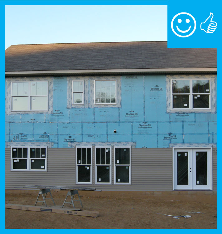
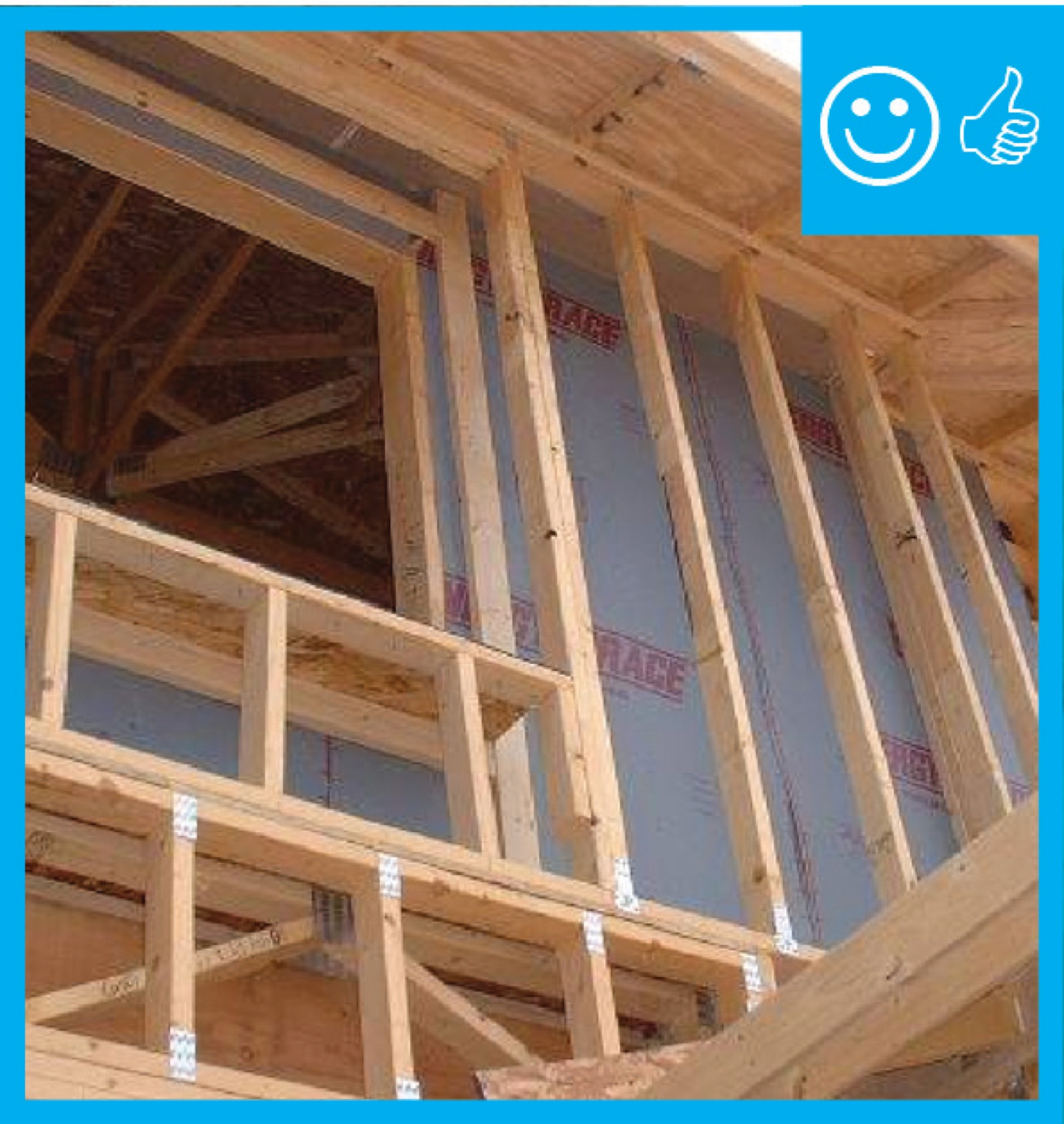
Right – Structural insulated sheathing can provide racking strength (lateral load resistance), and serve as an air barrier and thermal barrier if installed according to manufacturer’s specifications with taped, sealed seams
Image
Image

Right – This attic knee wall and the floor joist cavity openings beneath it are being sealed and insulated with spray foam.
Image
Image
Image

Image
Image
Image
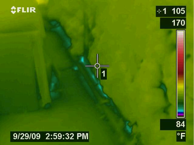
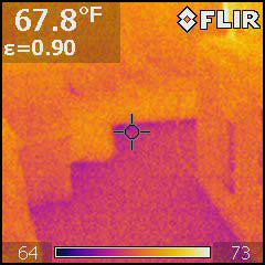
Right-- IR photo shows how effectively spray foam insulated/air sealed attic kneewall and the floor cavities under kneewall
Image
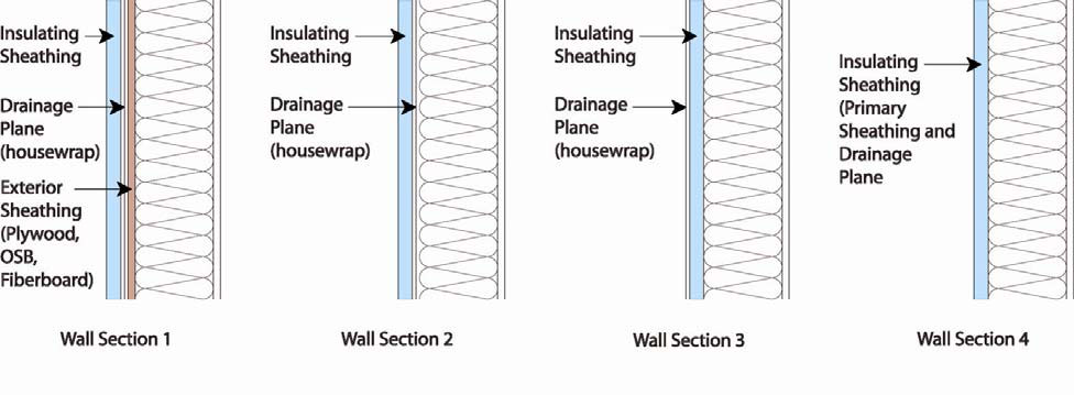
Rigid foam insulated sheathing placed exterior to house wrap, interior to house wrap, or take the place of the house wrap
Image
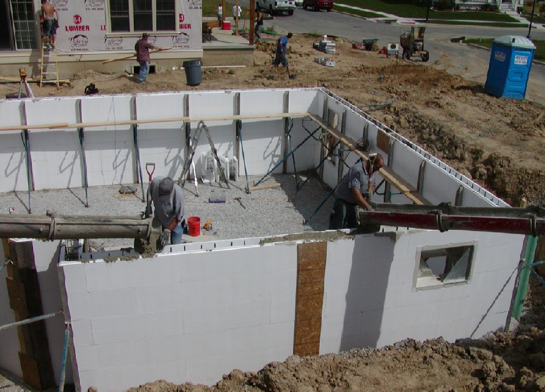
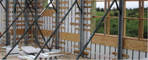
Scaffolding is continually raised as courses of foam brick are added so that the pour man can see both sides of the wall during the pour.
Image

SIP panel walls are less susceptible to air leakage and convection issues than stick-built walls
Image
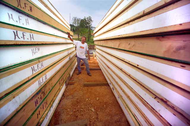
SIP panels should be stacked high, dry, and flat
Image
Image
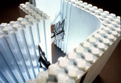
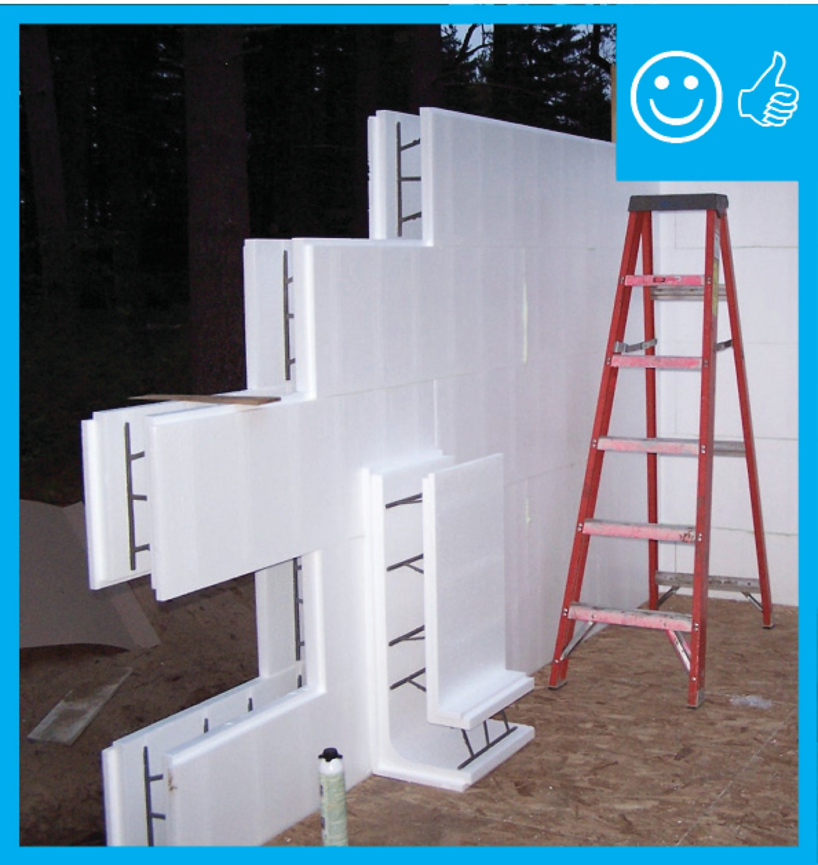
Special molded corners provide continuous insulation layer at the corners to improve structural strength and minimize thermal bridging
Image
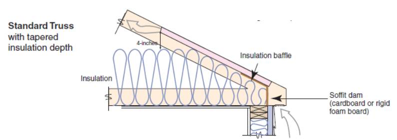
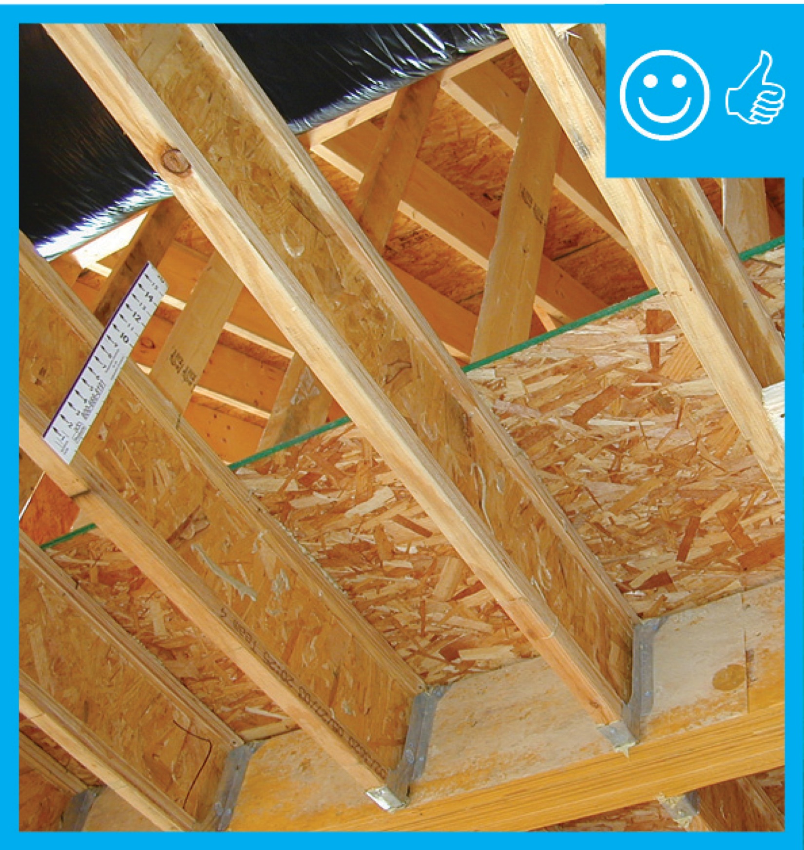
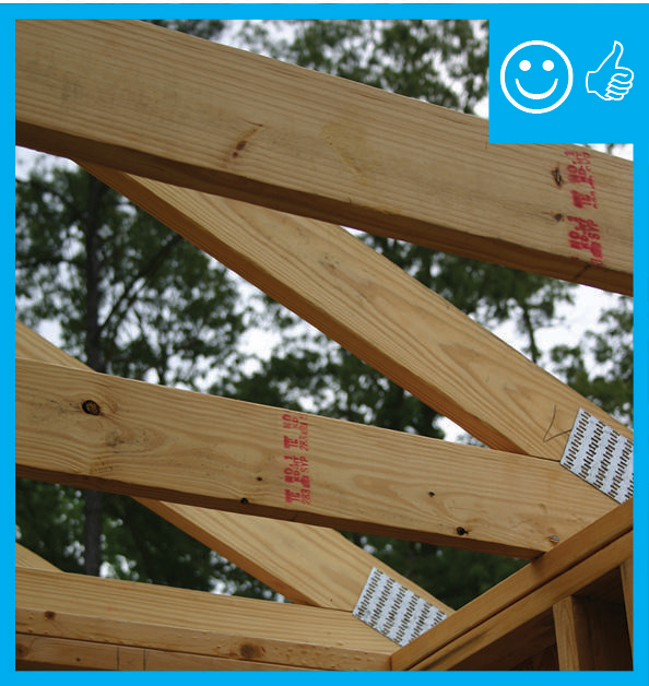
Standard roof trusses are narrow at the eaves, preventing full insulation coverage over the top plate of the exterior walls
Image
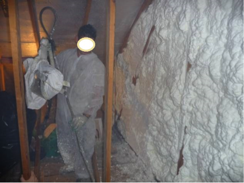
The attic kneewall and the open floor cavities under kneewall are both sealed and insulated in one step with spray foam insulation
Image
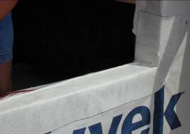
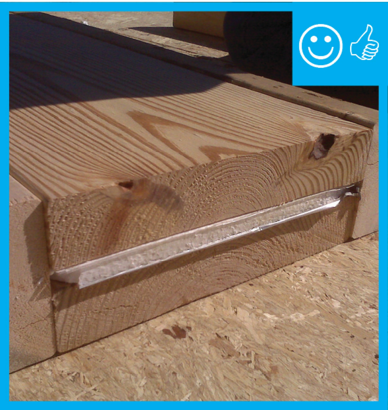
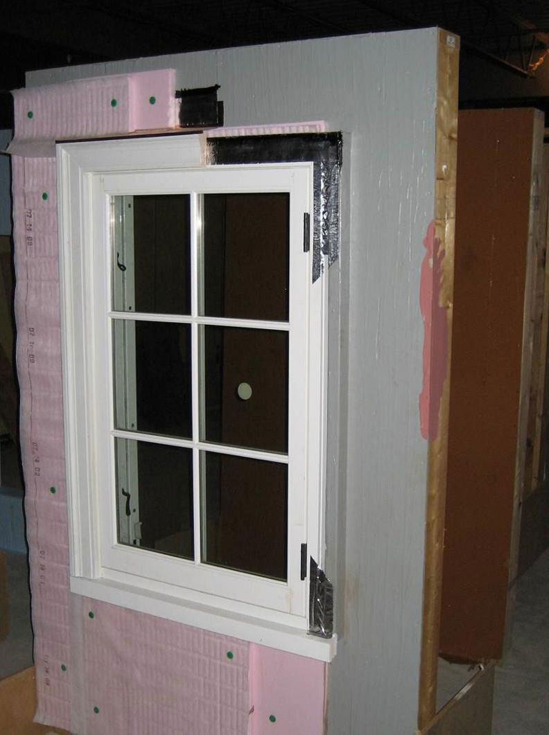
The back dam of the window sill will force water out
Image
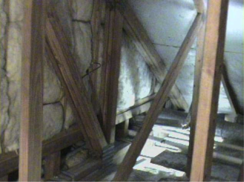
The floor cavities under this attic kneewall are completely open to the unconditioned attic space and a prime target for wind washing
Image
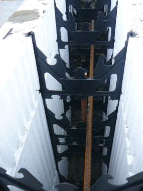
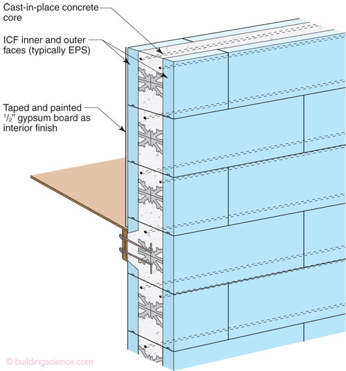
The ICF consists of foam forms that are held in place with plastic or metal spacers and reinforced with metal rebar
Image
Image
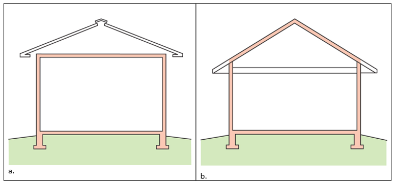
The thermal boundary for a gable roof can be located at either a) the flat ceiling with a vented attic or b) the roof line for an unvented attic
Image
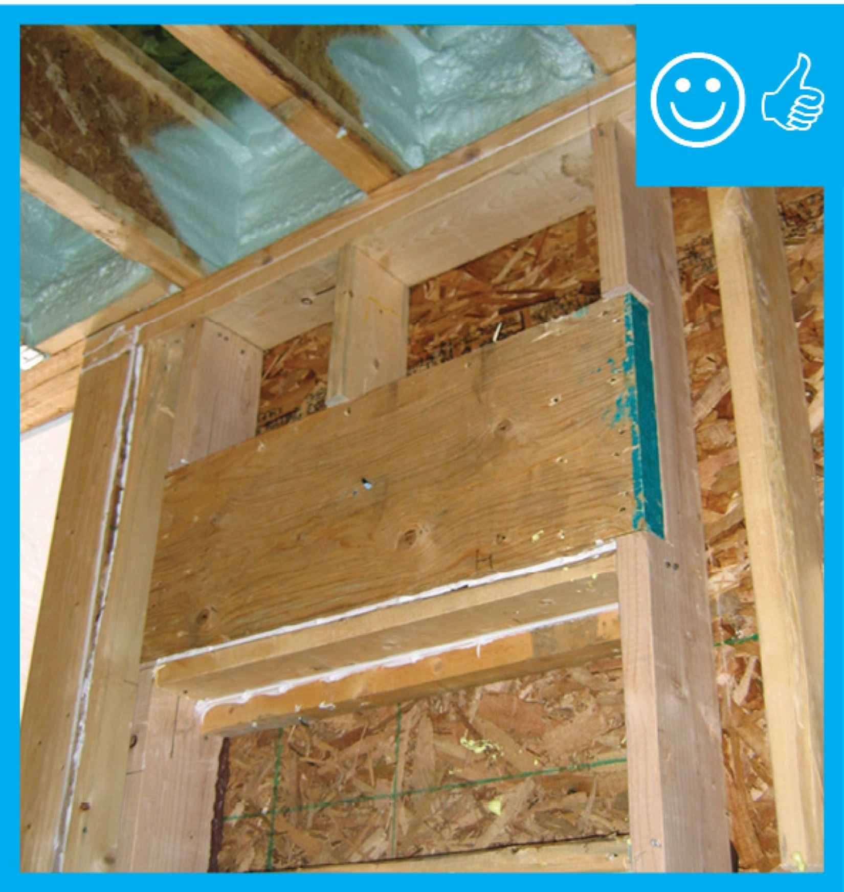
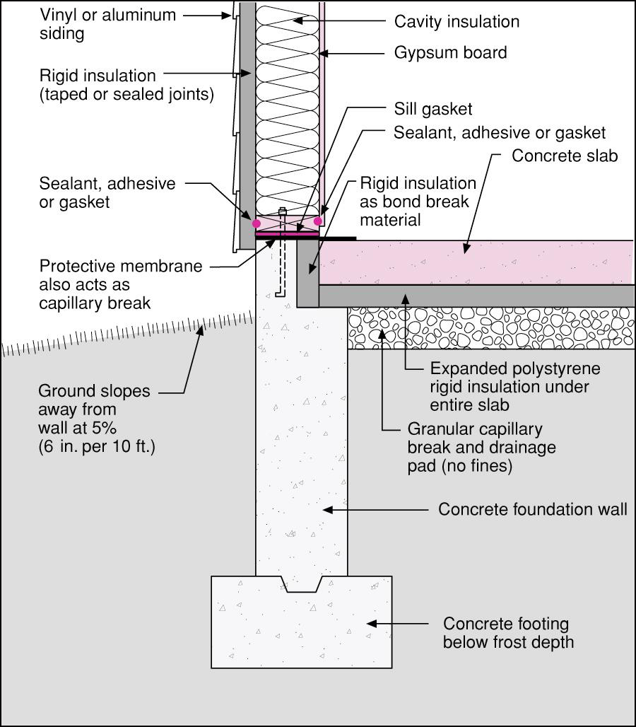
Thermal bridging is eliminated at the rim joist with the use of joist ledgers that are anchored in the wall
Image
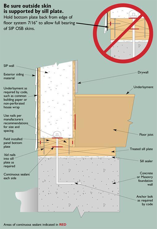
This foundation/floor/SIP wall detail shows recommended support of SIP wall panel at the sill plate
Image
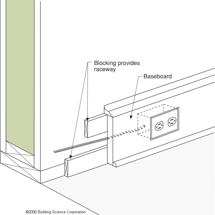
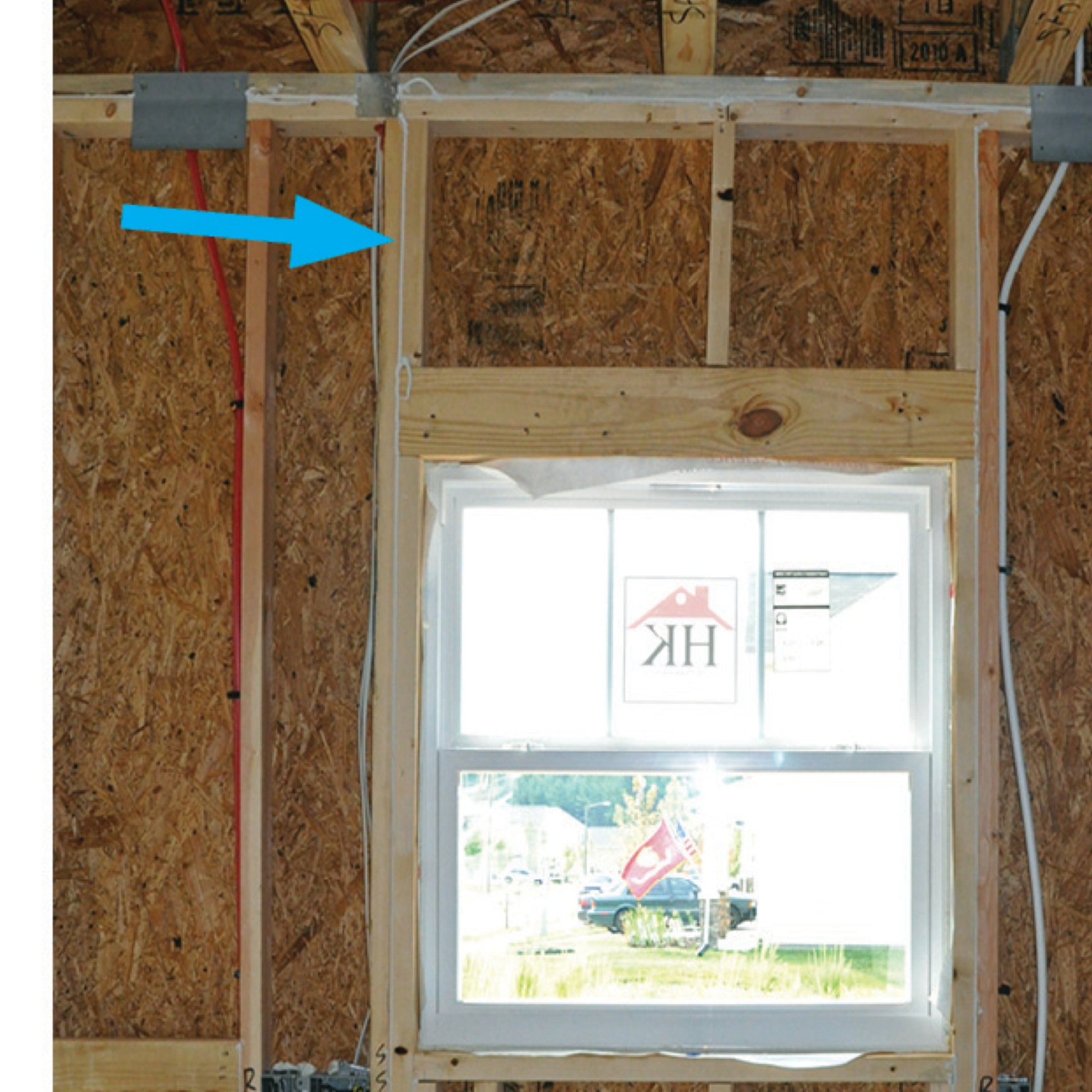
This technique for installing electrical wiring avoids the need to cut into the SIP panel
Image
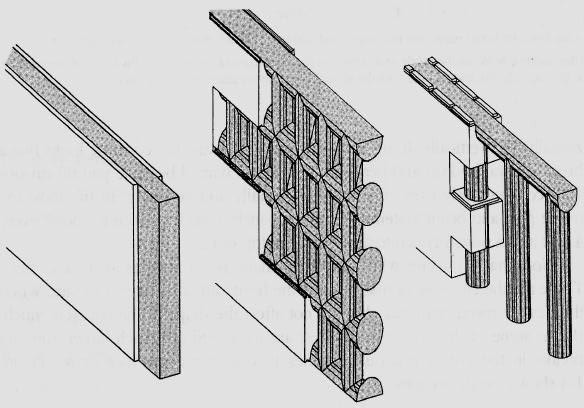
Three common ICF wall systems: the flat wall, the waffle wall, and the post-and-beam wall
Image
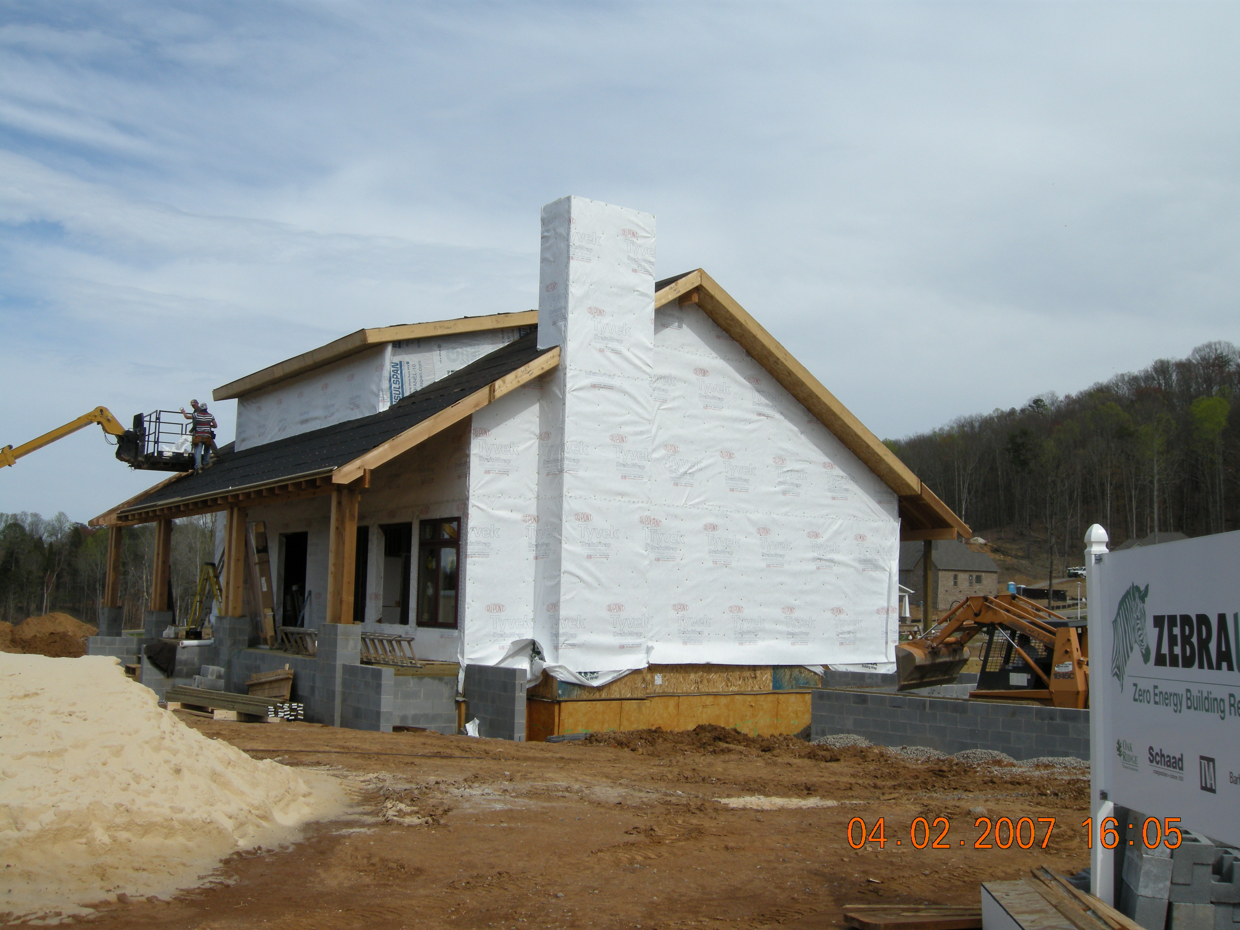
Two layers of high-permeability house wrap are installed to provide a drainage layer between the SIPS and the homes external cladding
Image
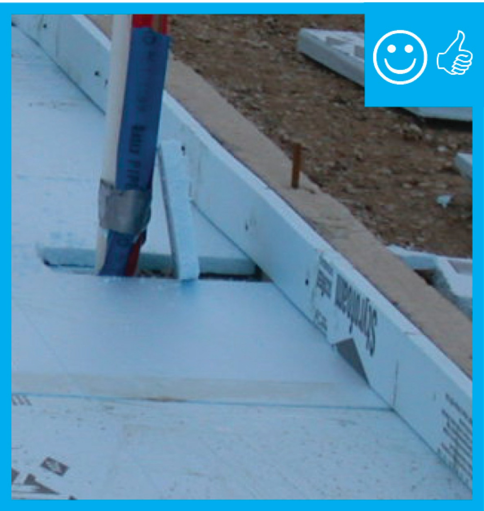
Two layers of XPS are installed with staggered seams over a liquid-applied membrane on the structural sheathing
Image
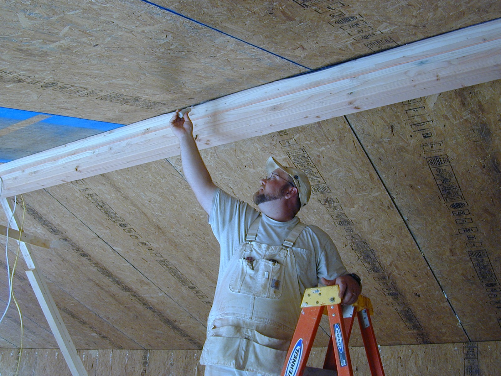
Use a smoke pencil to check for air leaks at SIP panel seams, especially along the ridge beam
Image
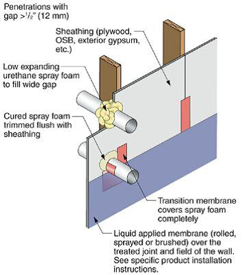
Use flashing tape to seal around any pipes or vents that penetrate through the foam
Image
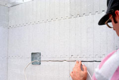
Utilities are commonly recessed into cutouts in the foam after concrete has been poured
Image
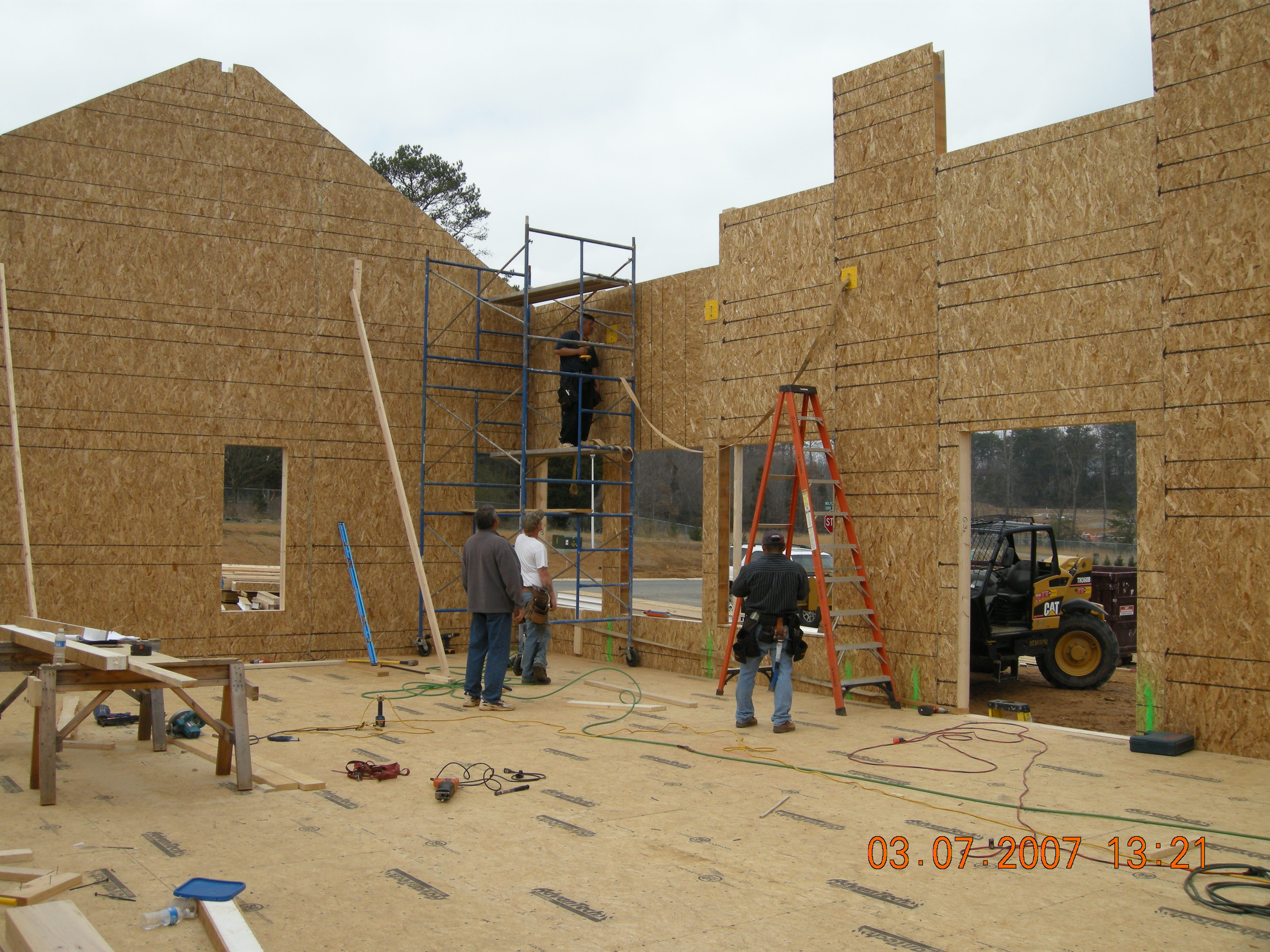
Walls are being assembled at this SIP house
Image