Showing results 1 - 250 of 422
Image
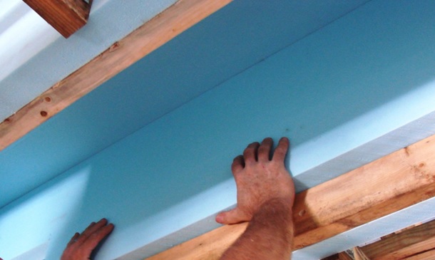
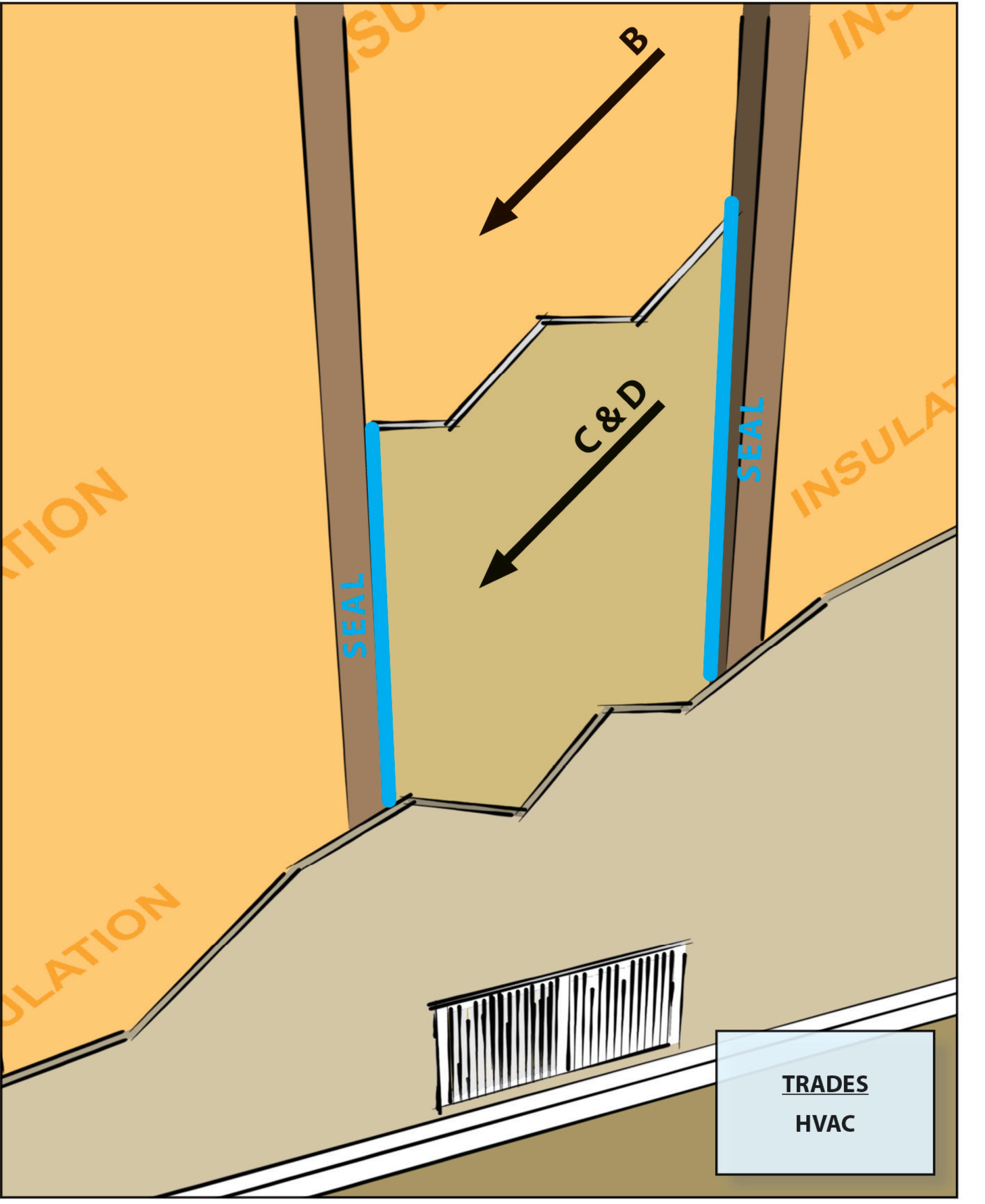
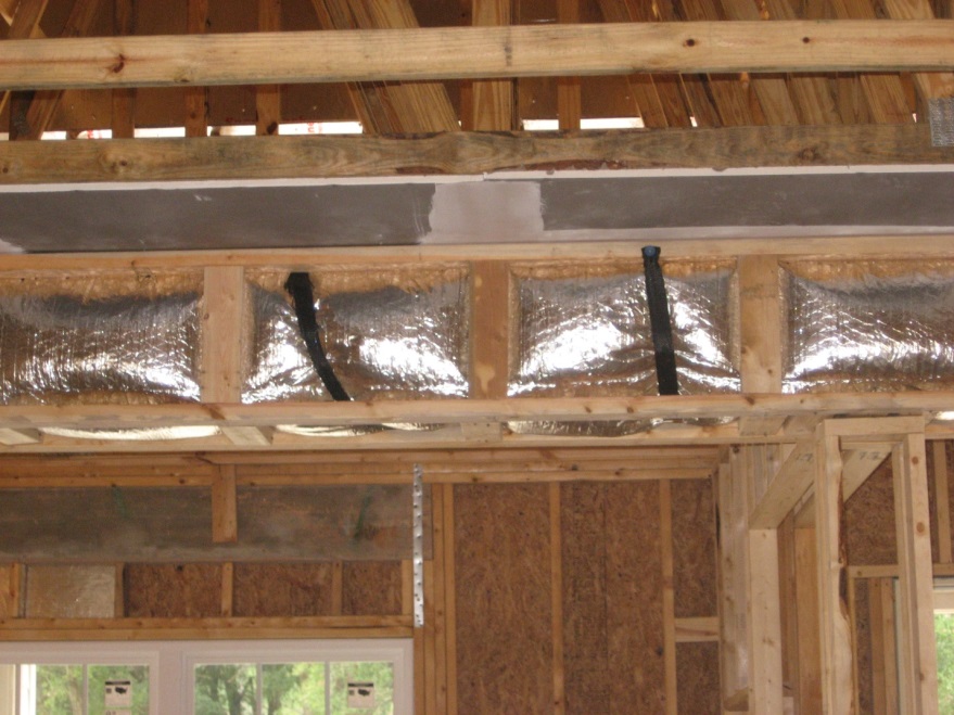
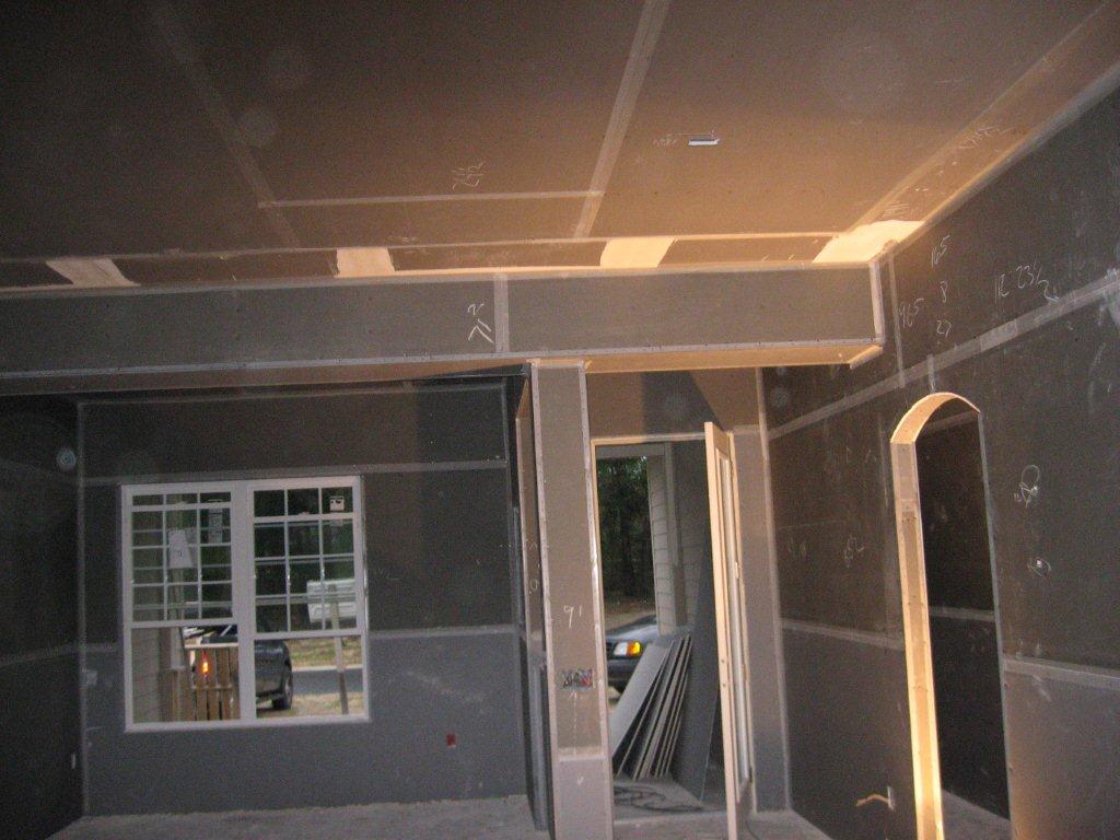
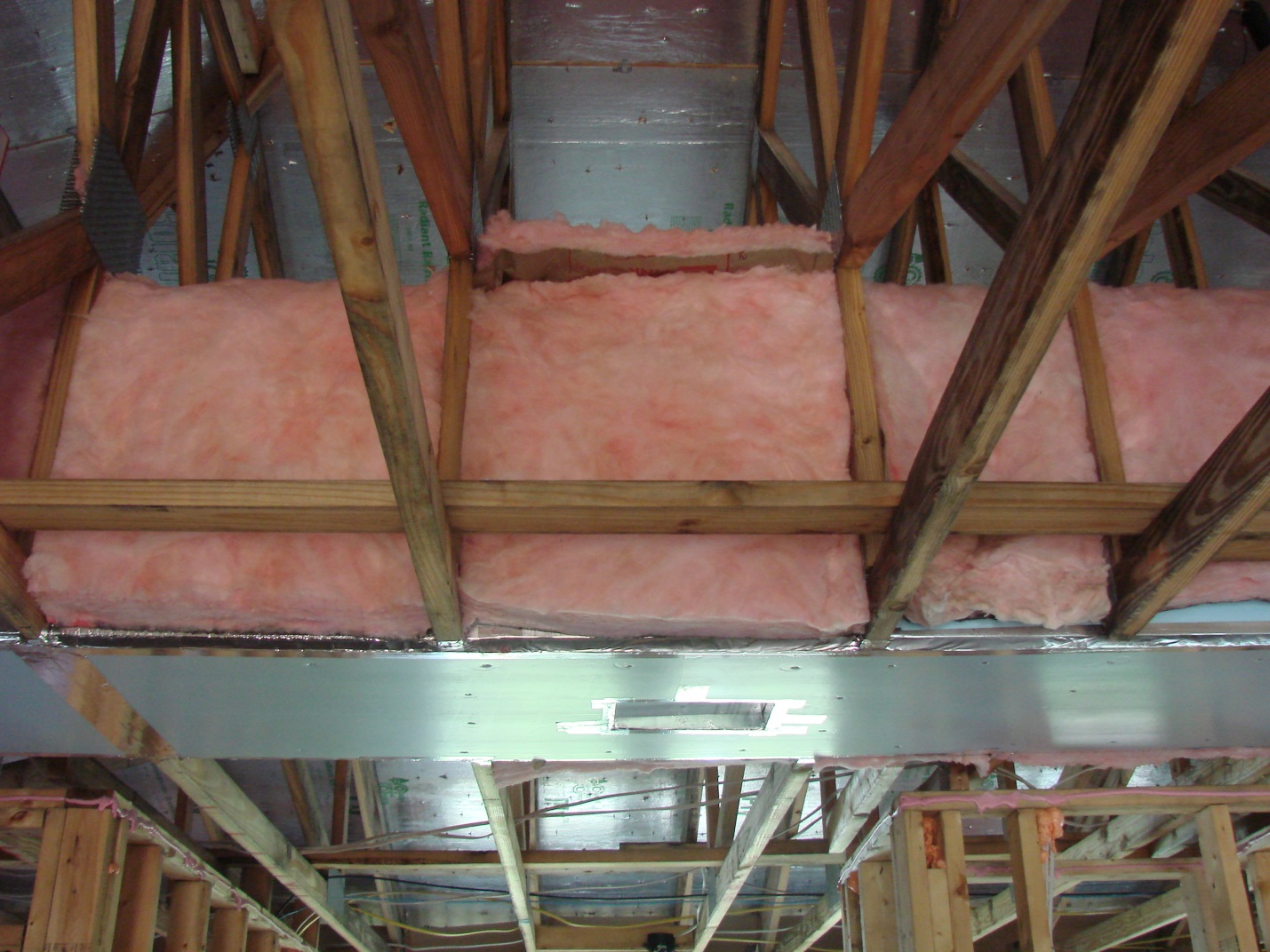
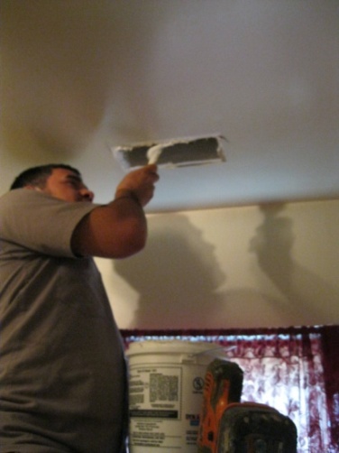
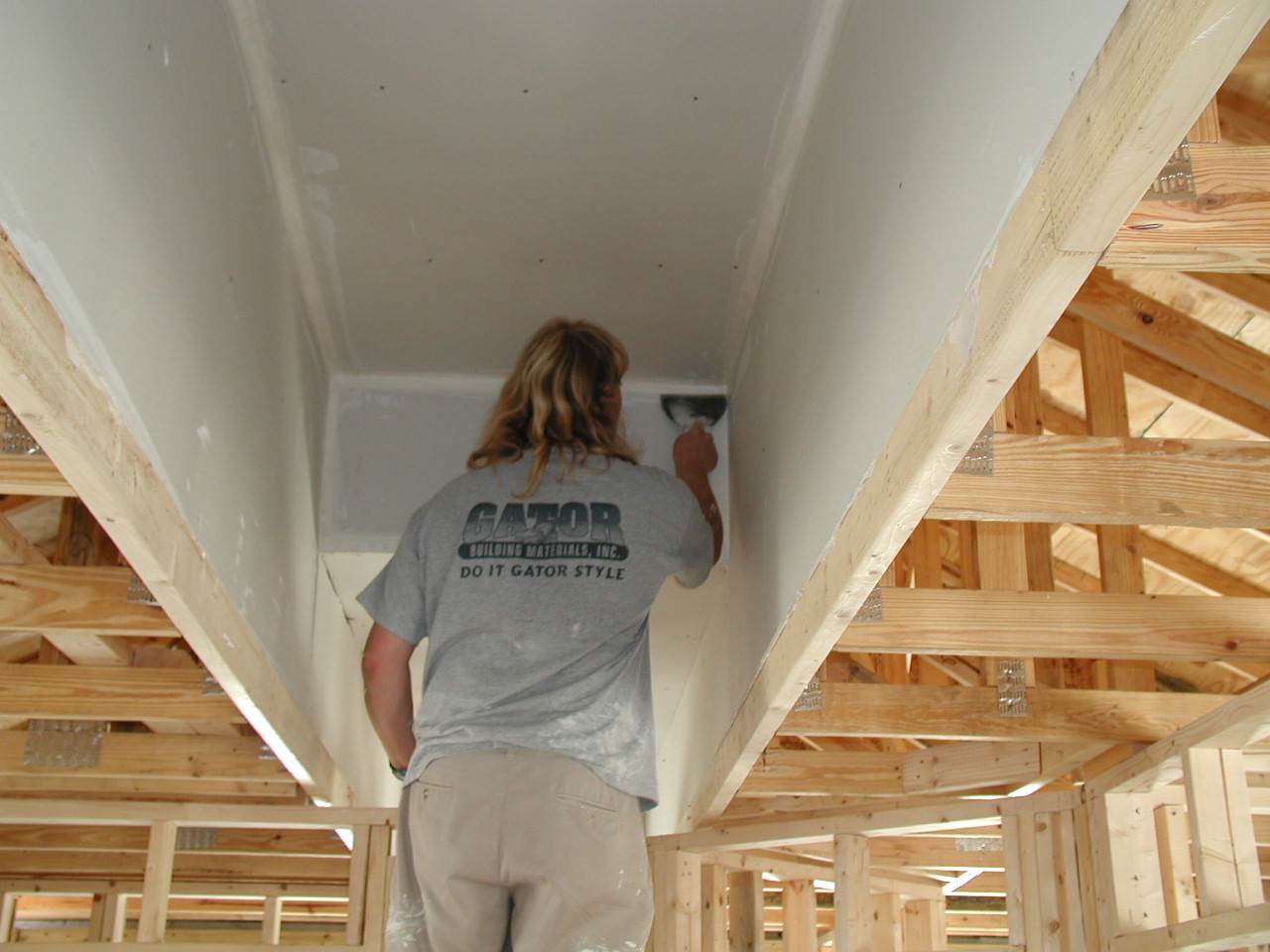
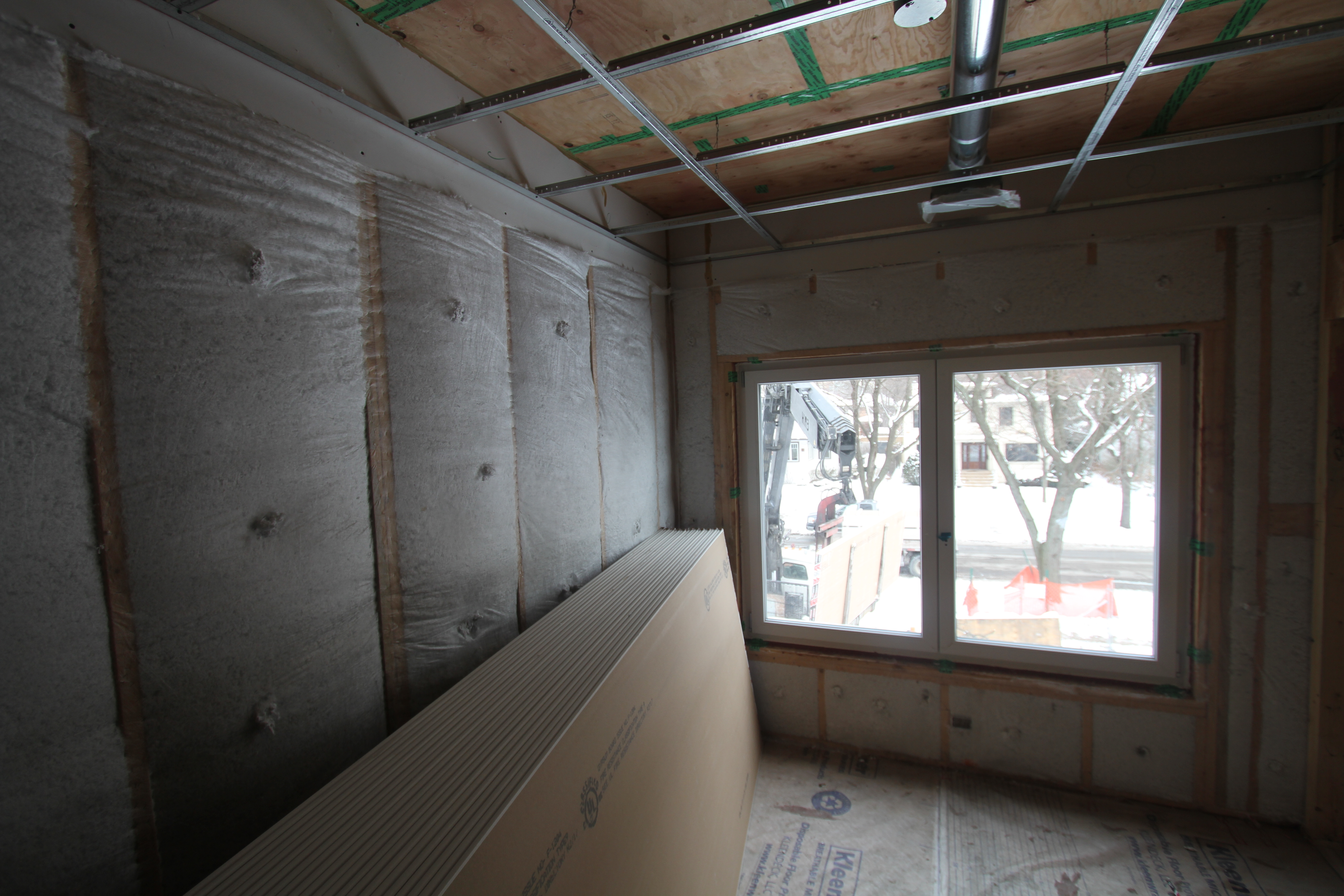
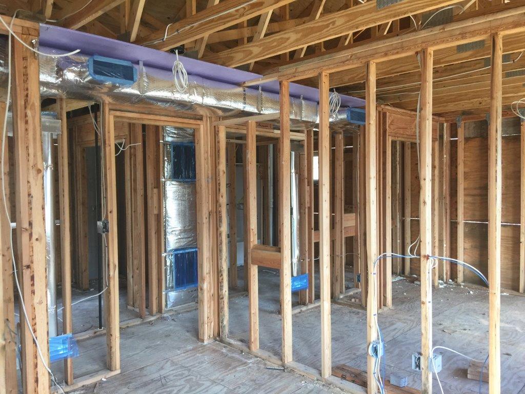
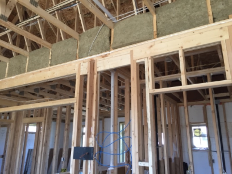
Right - Drywall is installed as an air barrier above the central hallway duct chase prior to installing the trunk ducts.
Image
Image
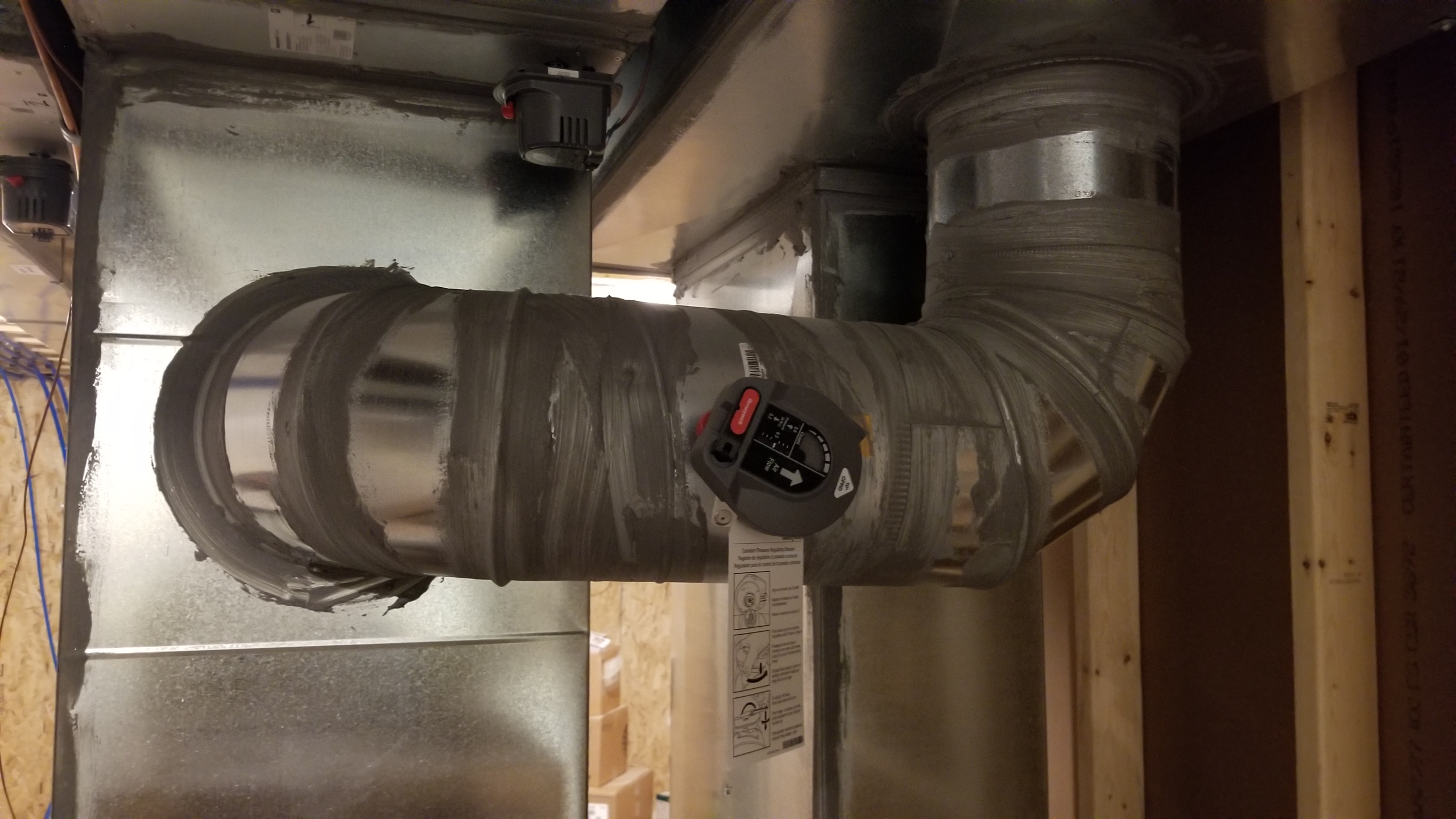
A constant airflow regulator is a modulating orifice that automatically regulates airflows in duct systems to constant levels
Image
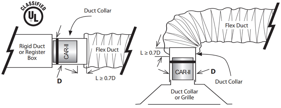
A constant airflow regulator is fitted into the neck of the supply duct to control air flow to deliver the design airflow regardless of pressure variations
Image
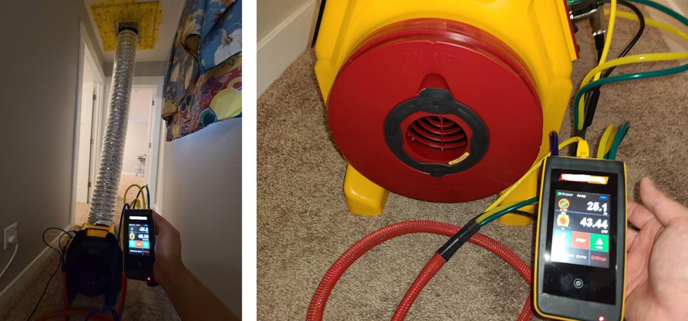
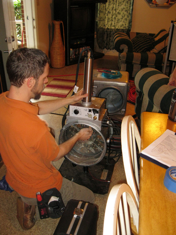
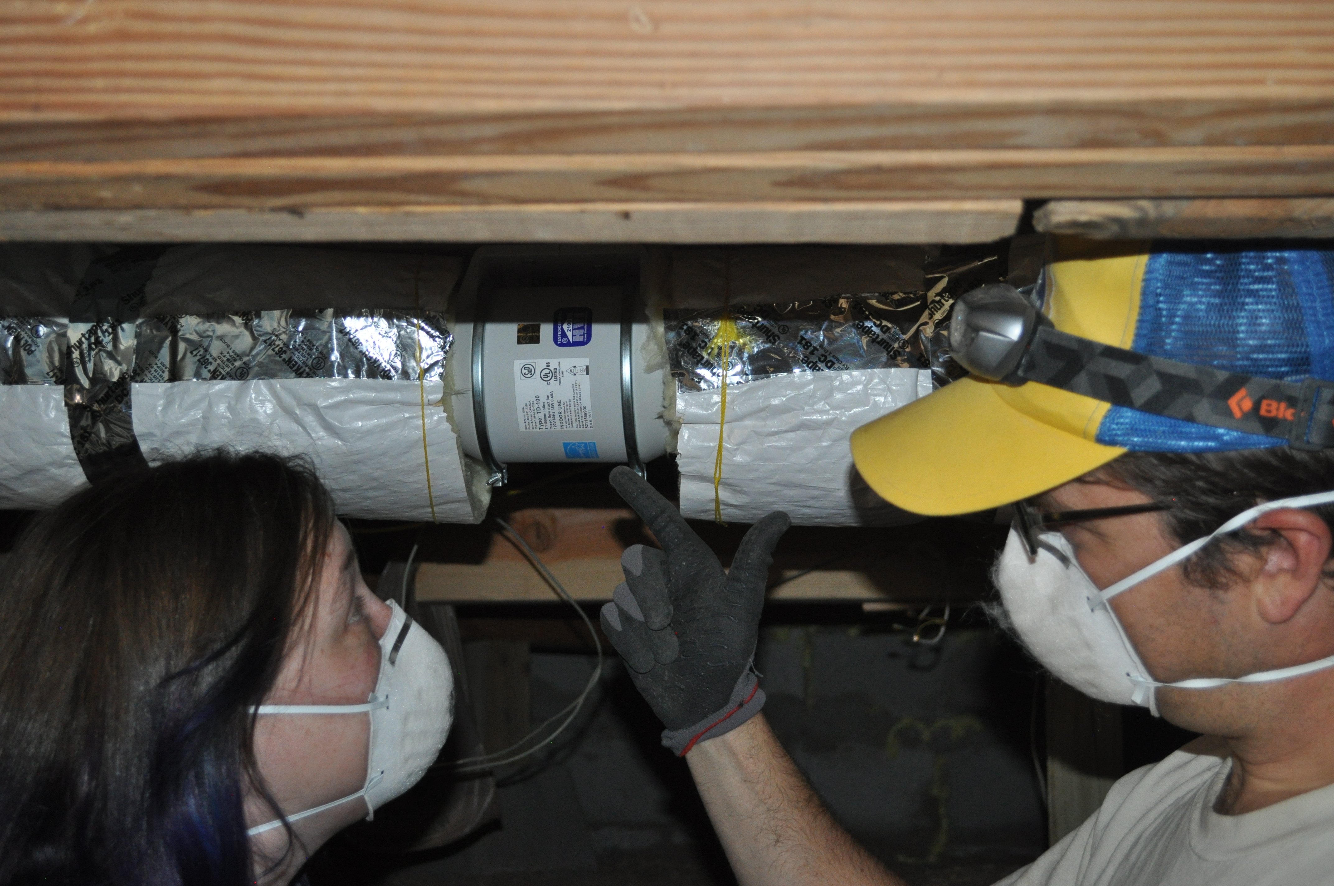
A duct leakage test is performed on a ducted heat pump system using a duct tester (blower fan) and a digital manometer.
Image
A ducted central return brings air from central return registers back to the air handler through insulated, air-sealed ducts
Image
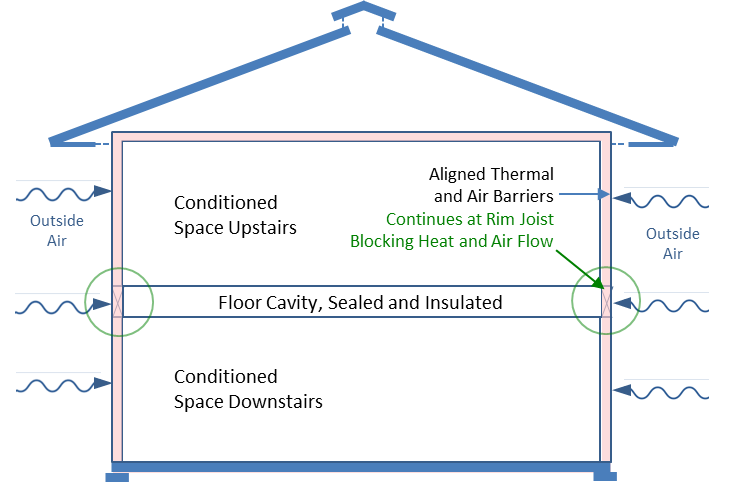
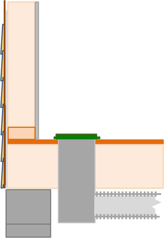
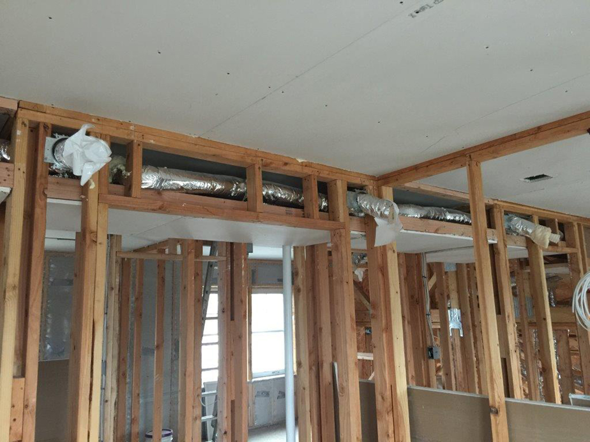
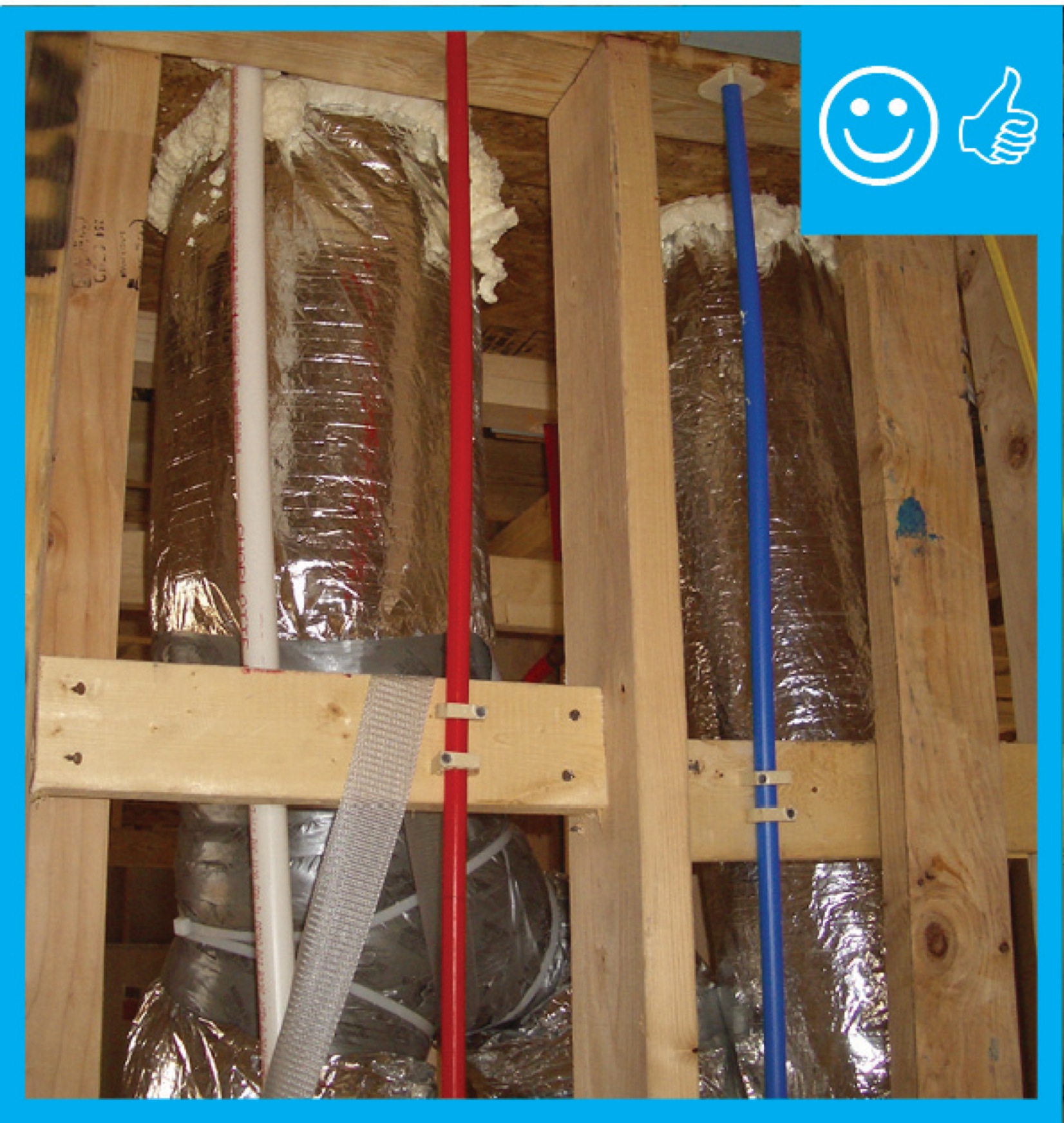
A floor cavity between the first and second floor can provide a conditioned space for HVAC ducts if the rim joists are insulated and air sealed, if sufficient space is available, and if open-web floor joists are used
Image
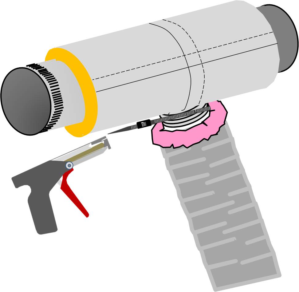
A nylon draw band and tensioning tool are used to secure the inner coil of the pre-insulated flexible duct
Image

A nylon draw band and tensioning tool are used to secure the inner liner of the pre-insulated flexible duct
Image
Image
A second layer of rigid insulation is installed over the 2 in. by 4 in. retaining strip
Image
A technician assembles the spray sealant injection system to seal HVAC ducts from the inside
Image

Image
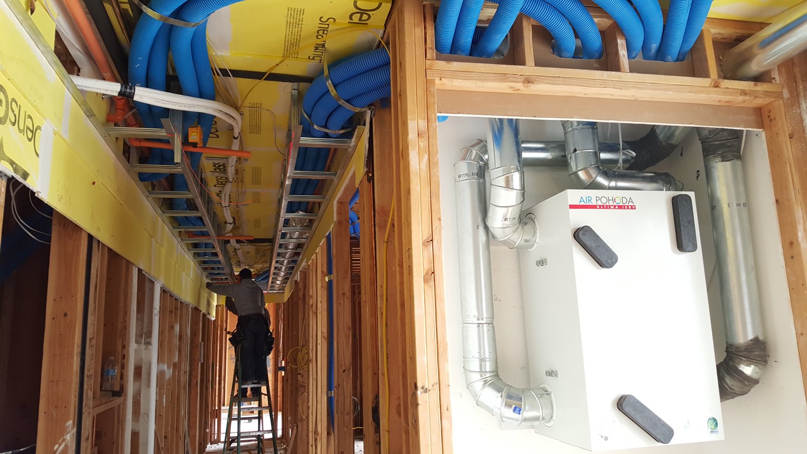
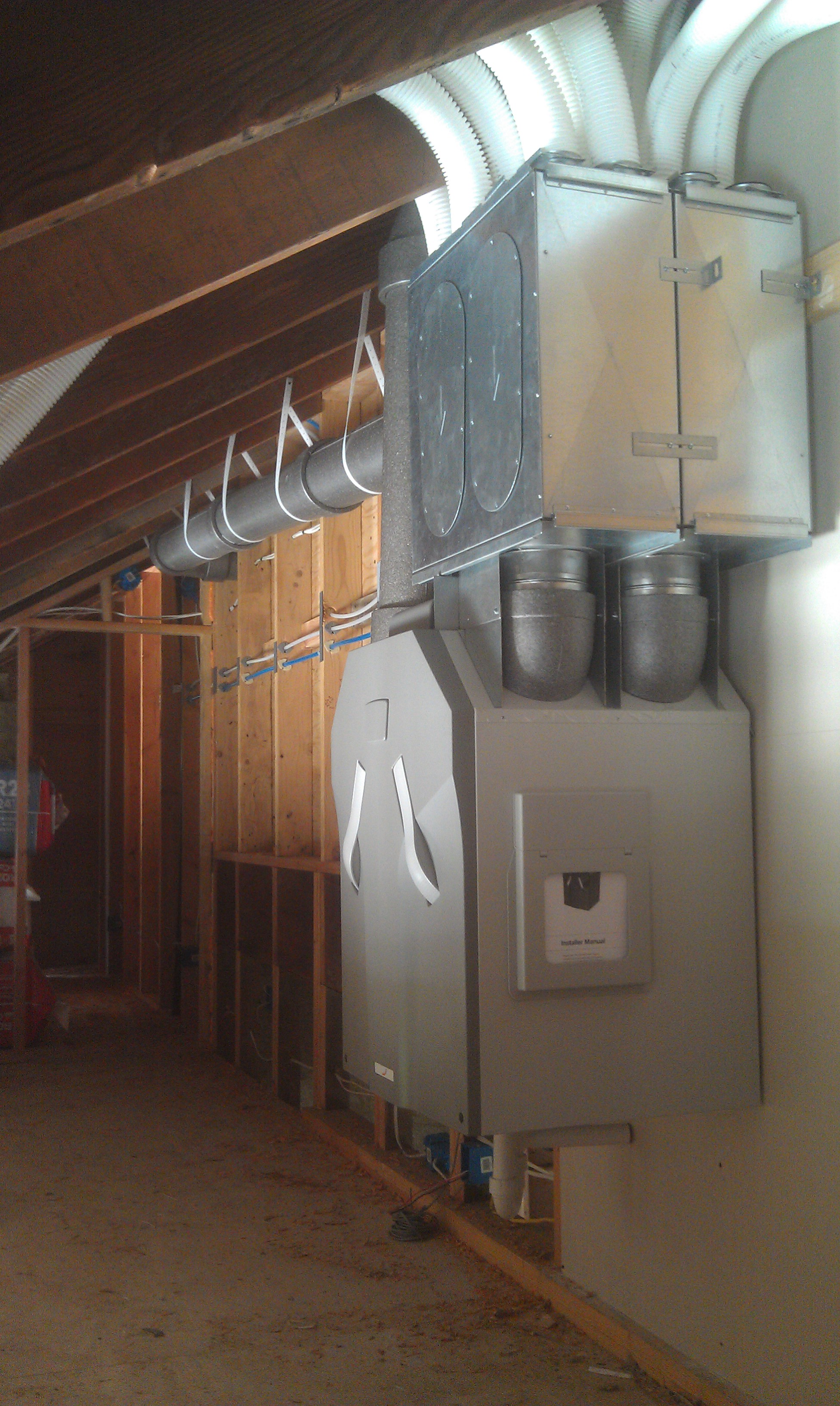
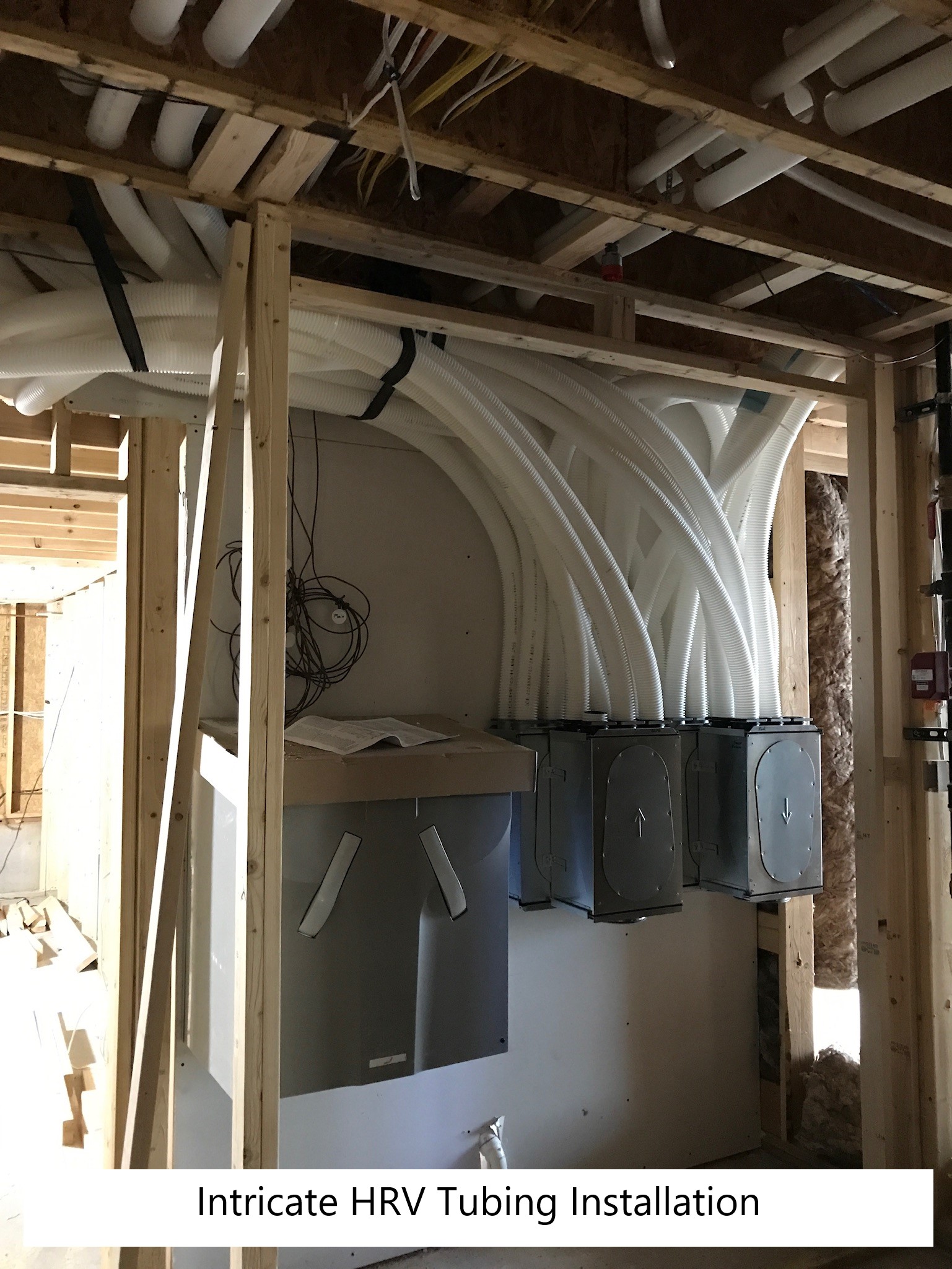
A triple-filtered energy recovery ventilator is installed with individual supply ducts to provide fresh air to each room.
Image
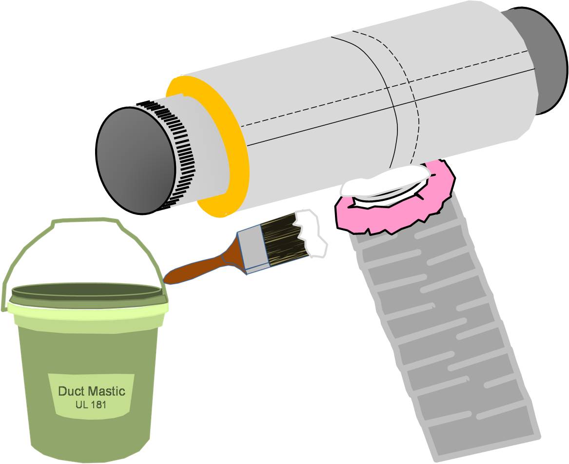
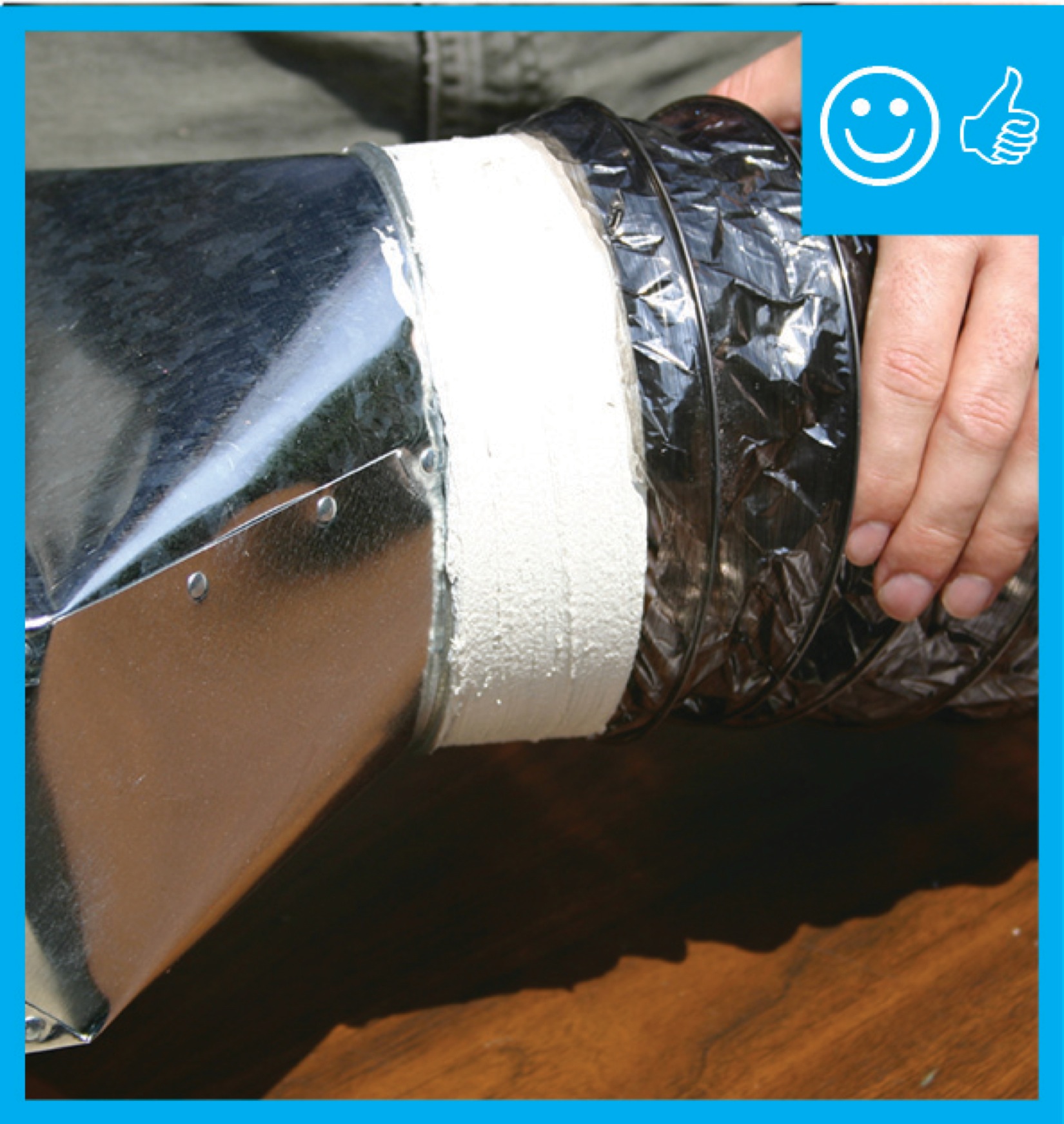
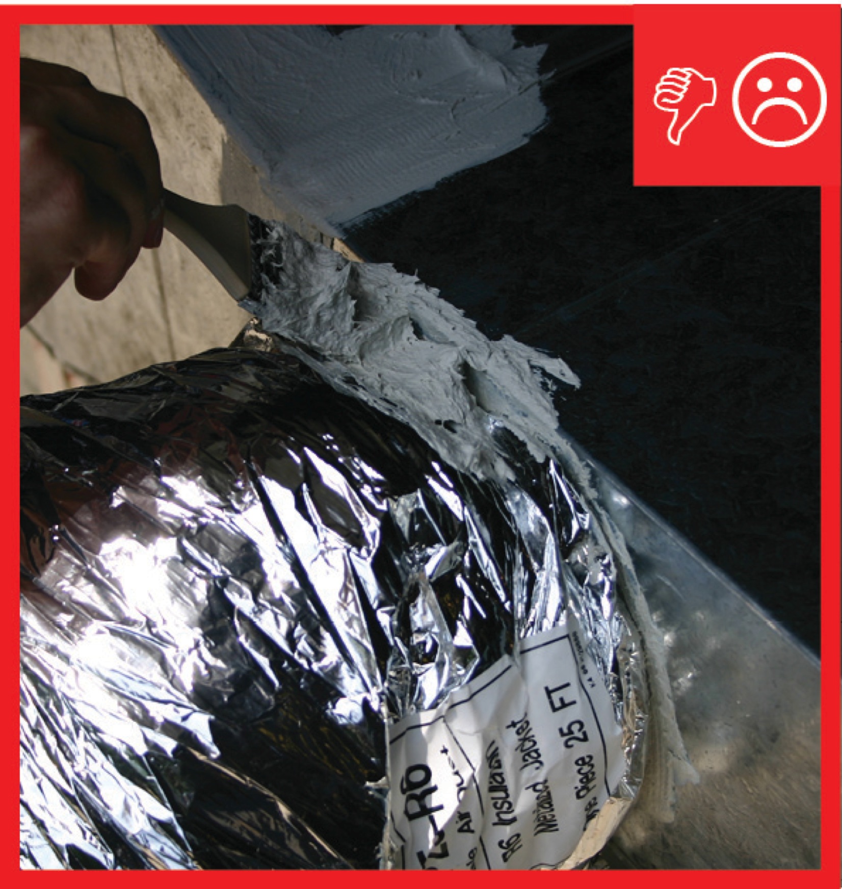
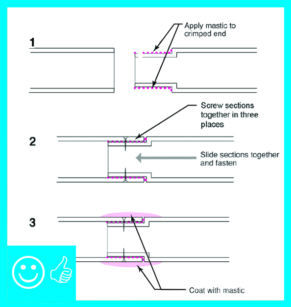
After securing the inner coil, cover the draw band and the seam with a generous amount of mastic
Image
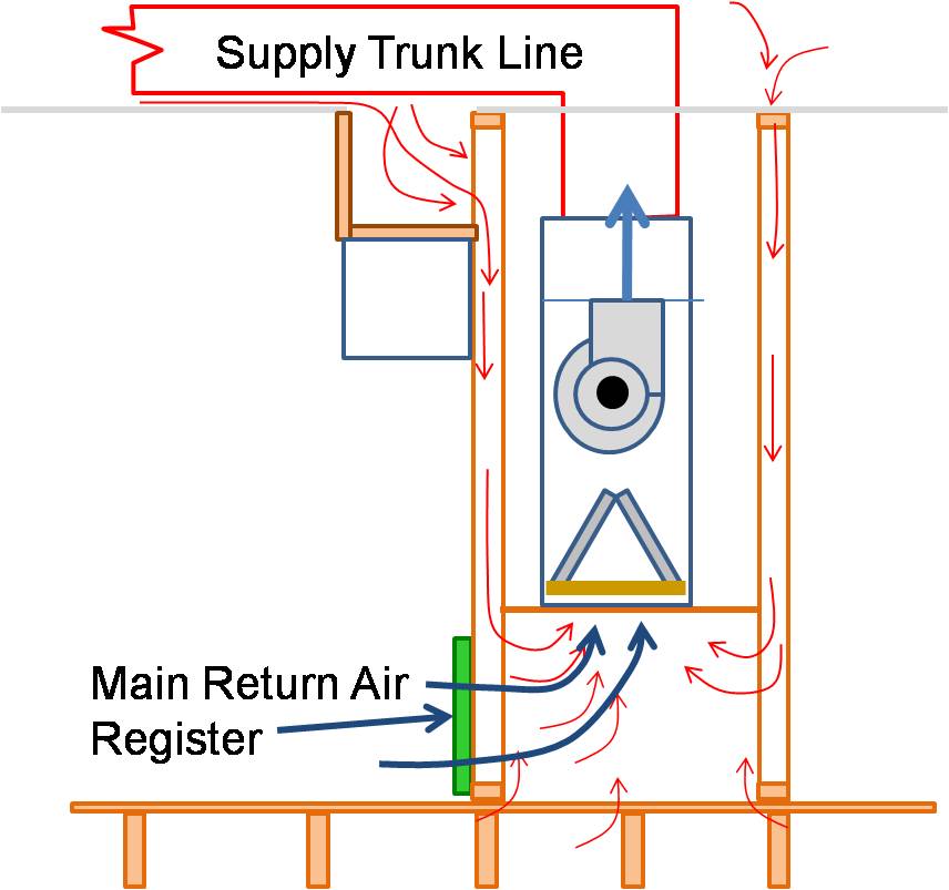
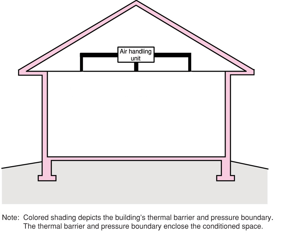
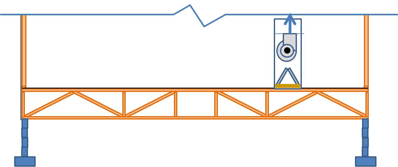
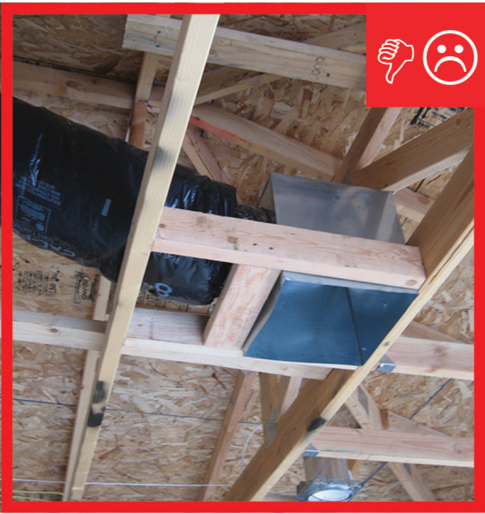
Air handler platforms used as return air plenums can draw air from vented attics and crawlspaces through other connected framing cavities
Image
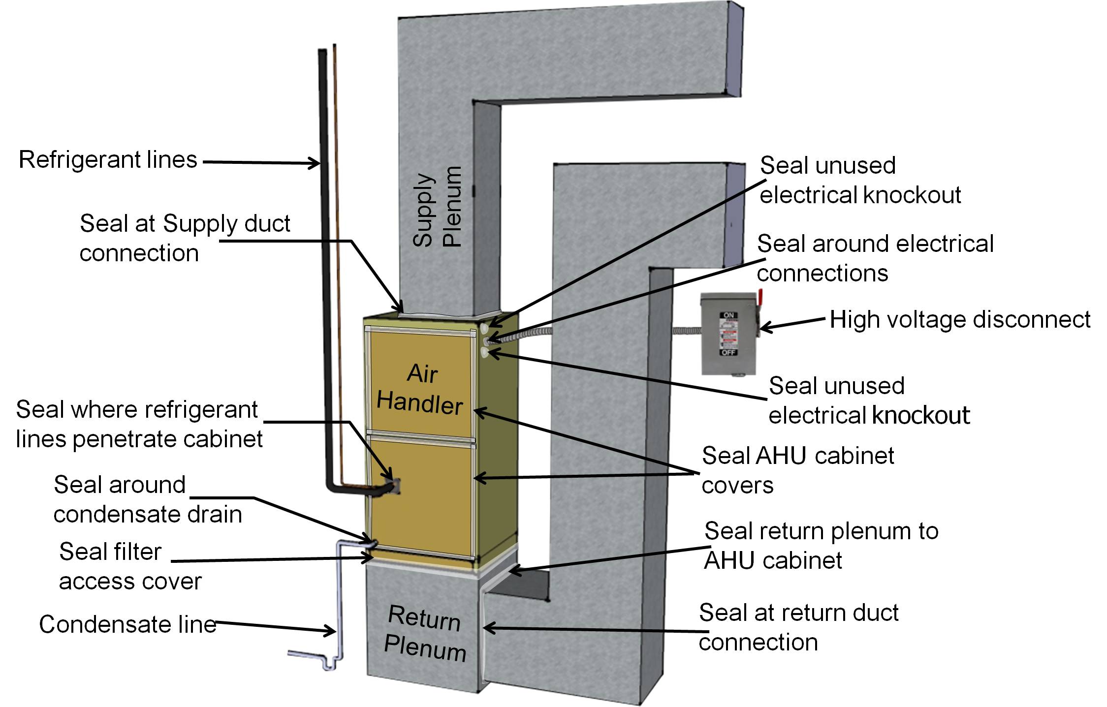
Air seal a heat pump or air conditioner air handler cabinet at all seams, holes, and junctions
Image
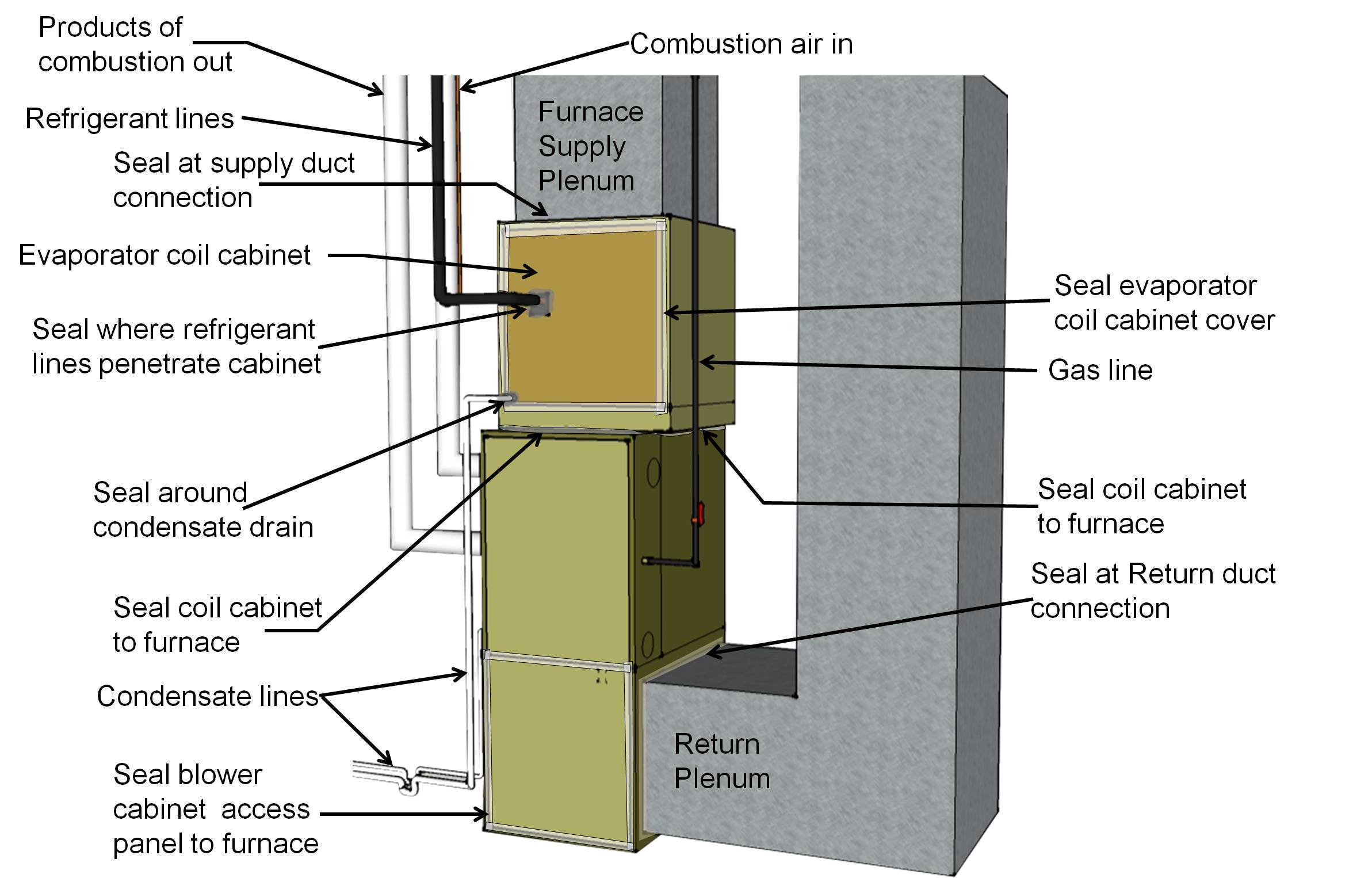
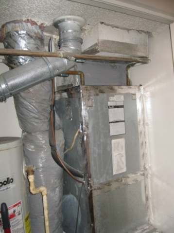
Air seal all holes and seams in the furnace cabinet with mastic, foil tape, or putty
Image
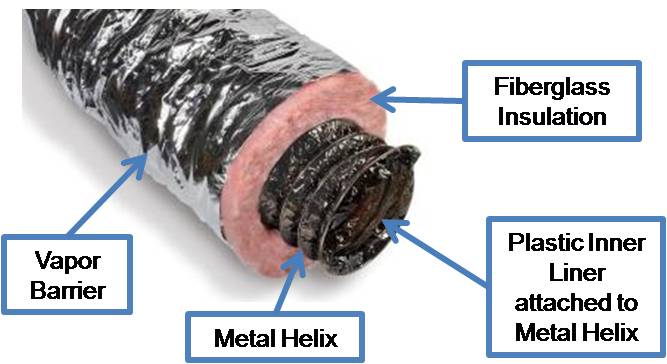
Air seal and insulate flex ducts
Image
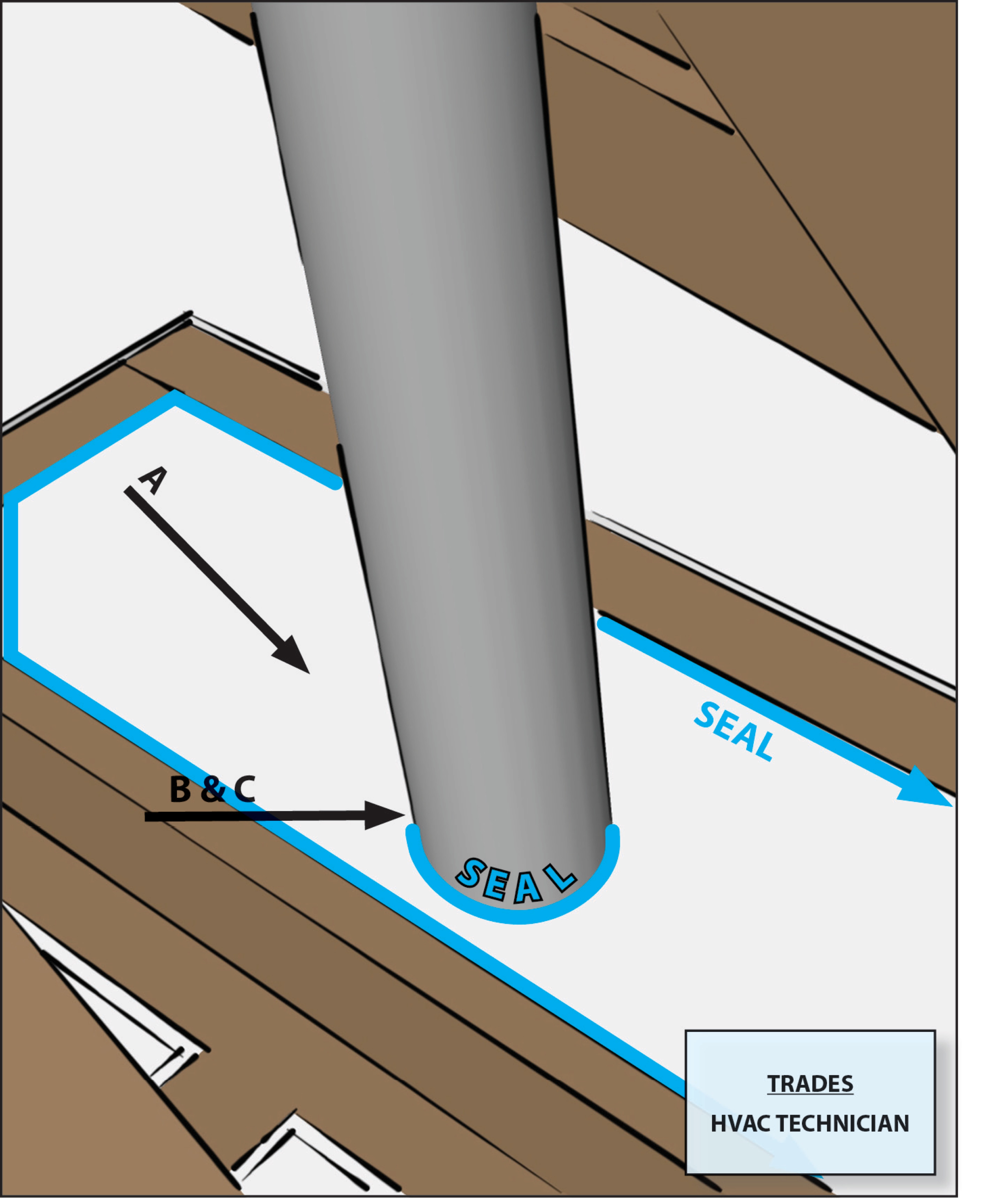
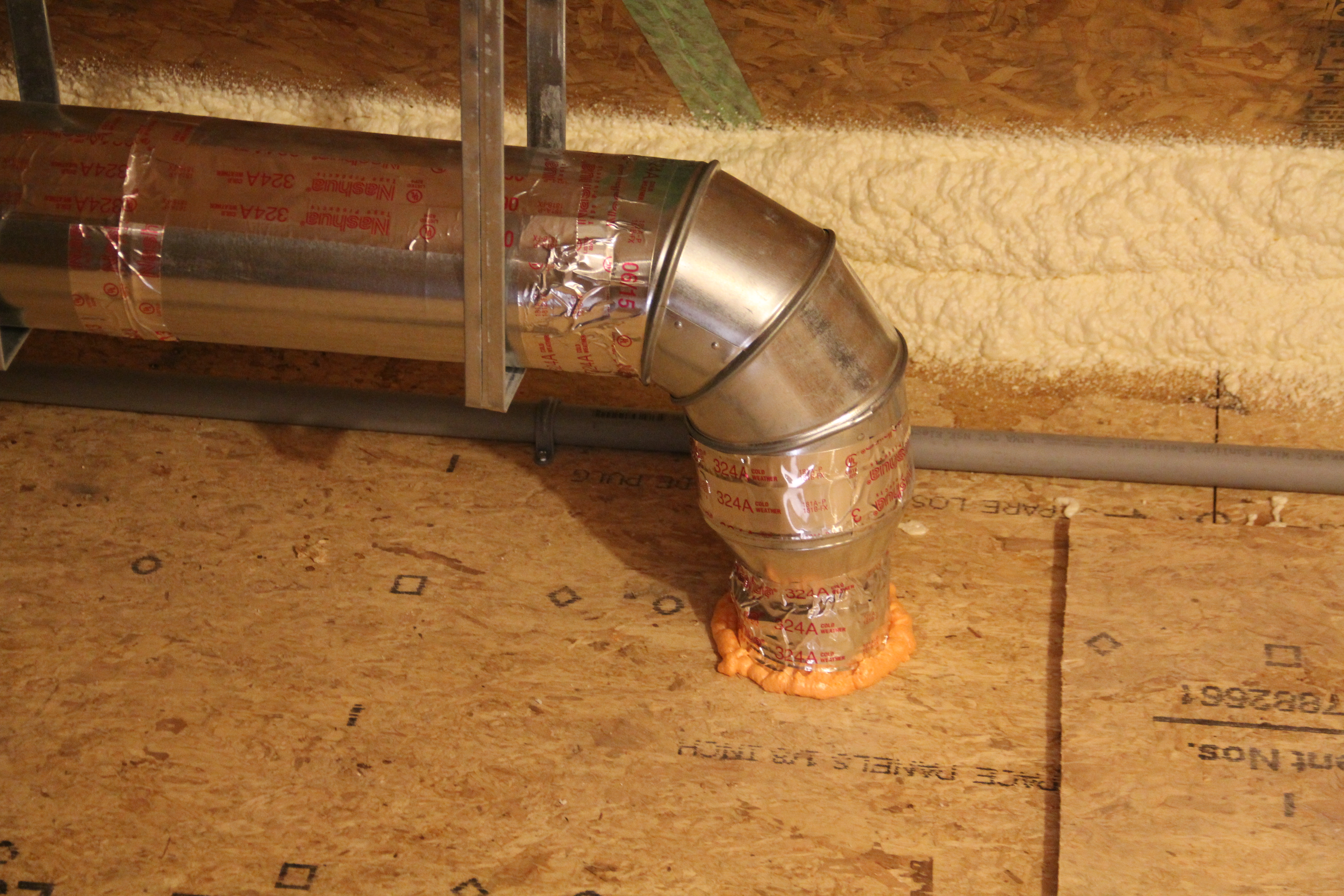
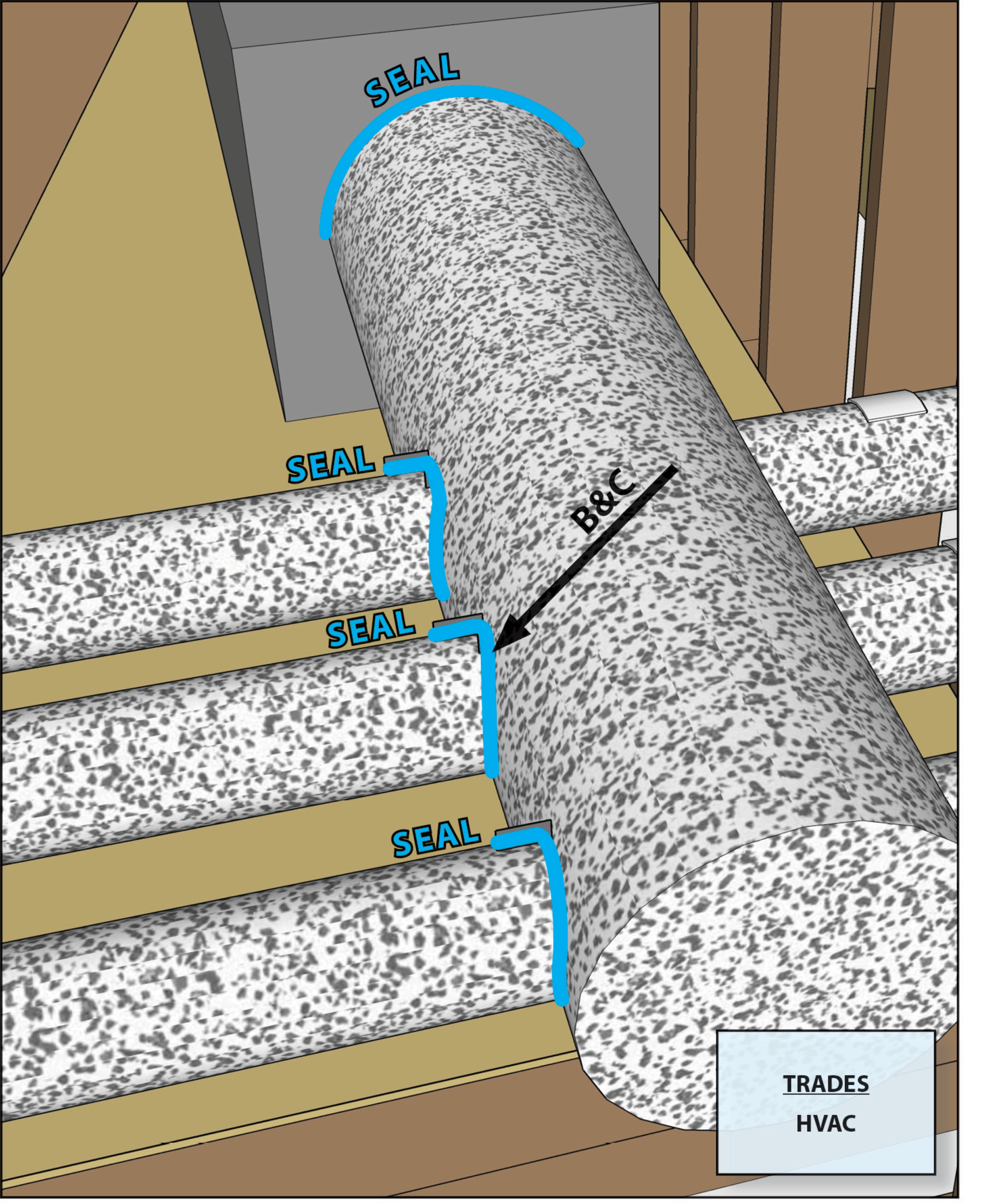
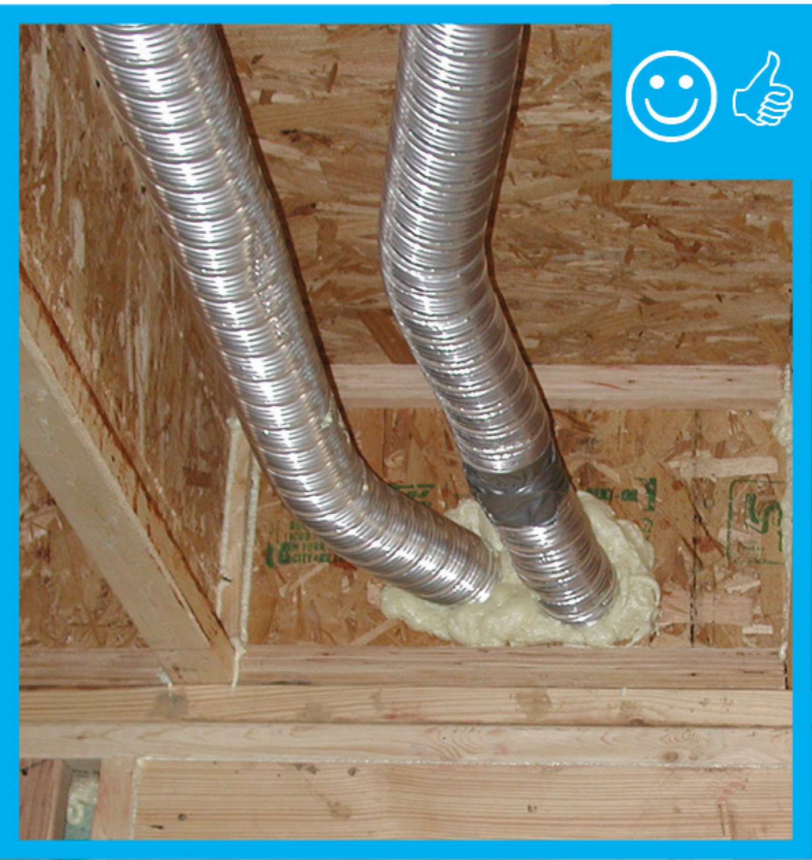
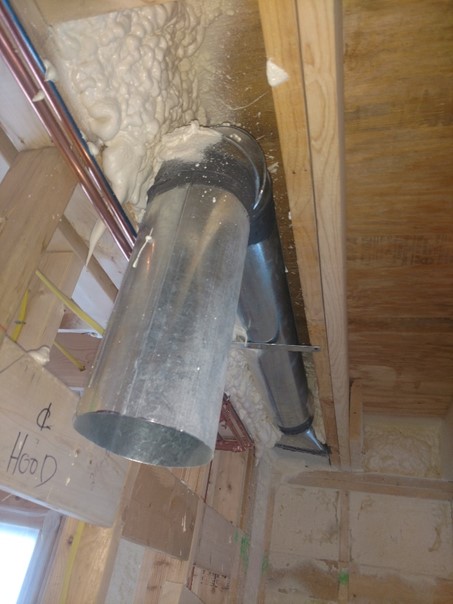
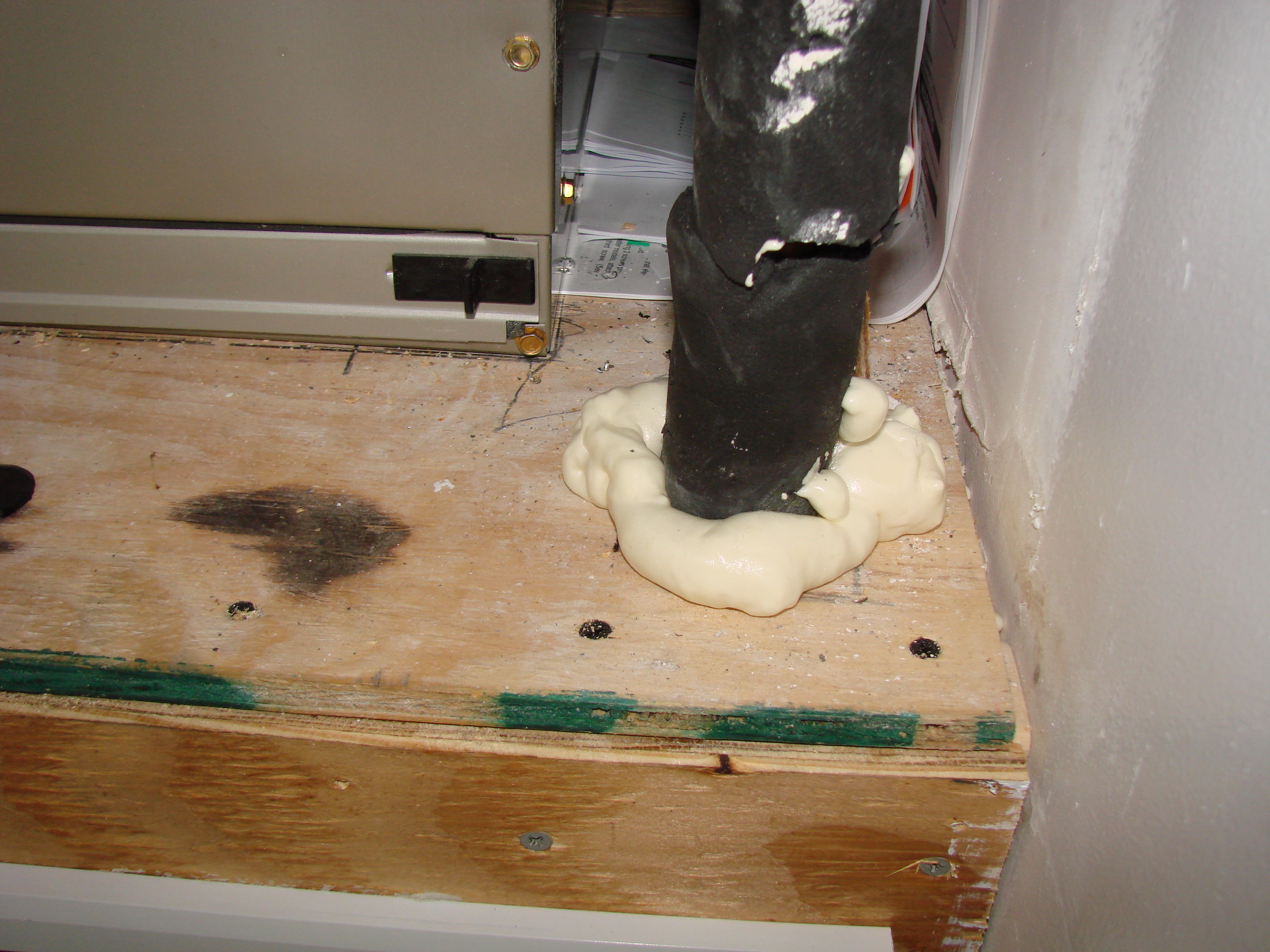
Air seal around all duct shafts and flues installed through ceilings, walls, or flooring to keep conditioned air from leaking into unconditioned space.
Image
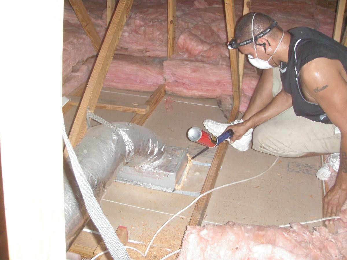
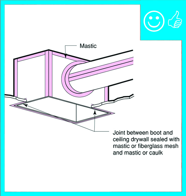
Air seal duct boot to ceiling by installing fiberglass mesh tape and mastic over seam
Image
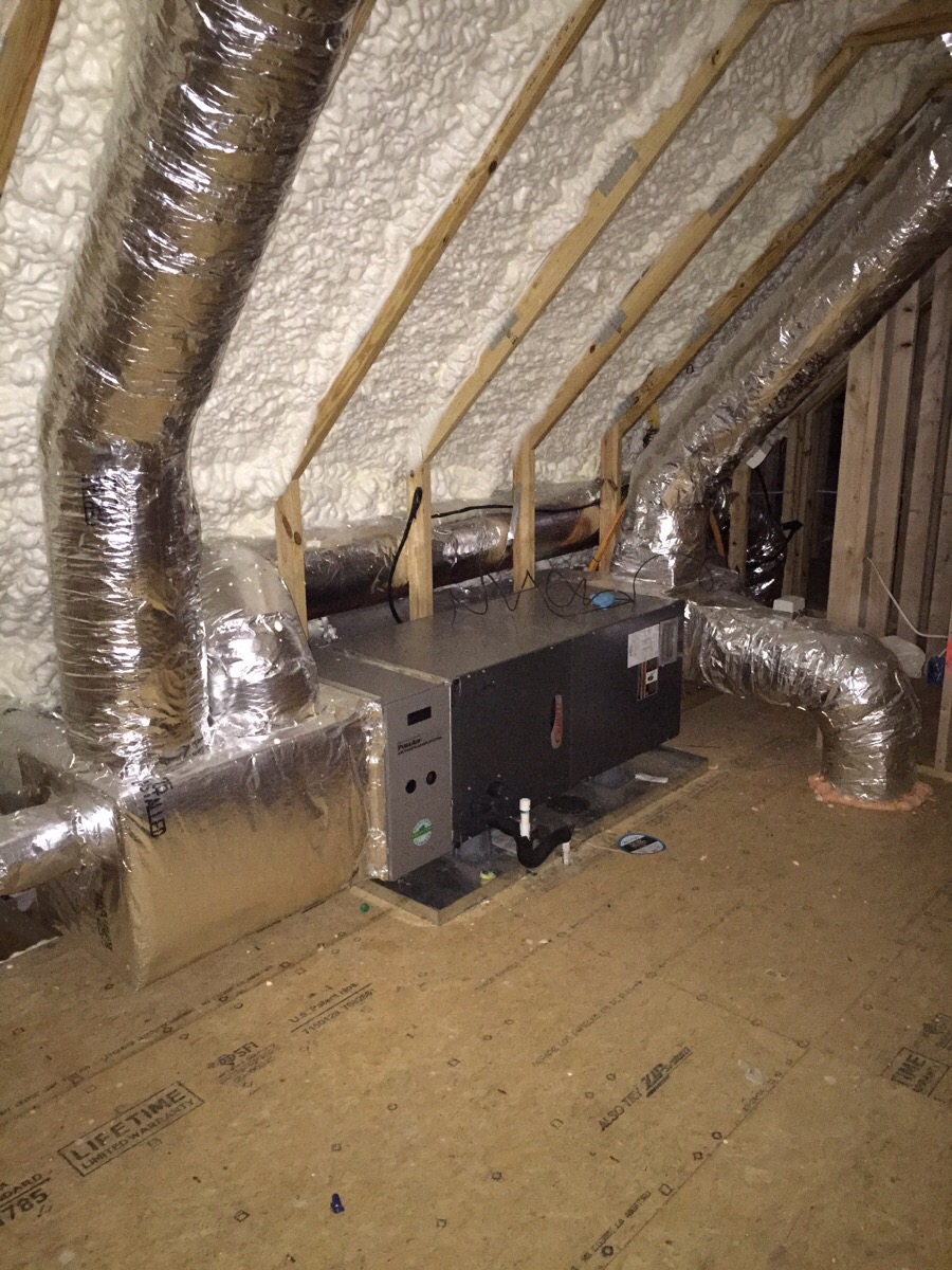
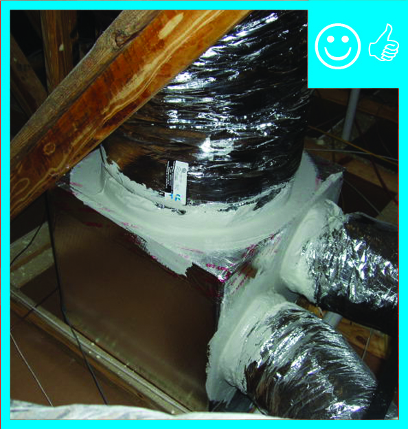
All of the ductwork for the efficient (8.5 HSPF, 15 SEER) heat pump is mastic sealed and installed in conditioned space.
Image
All other supply ducts and all return ducts in unconditioned space have insulation ≥ R-6
Image
An energy recovery ventilator provides filtered fresh air to every room in the house.
Image

An in-line airflow station installed in rigid duct provides a location to measure ventilation airflow
Image
Image
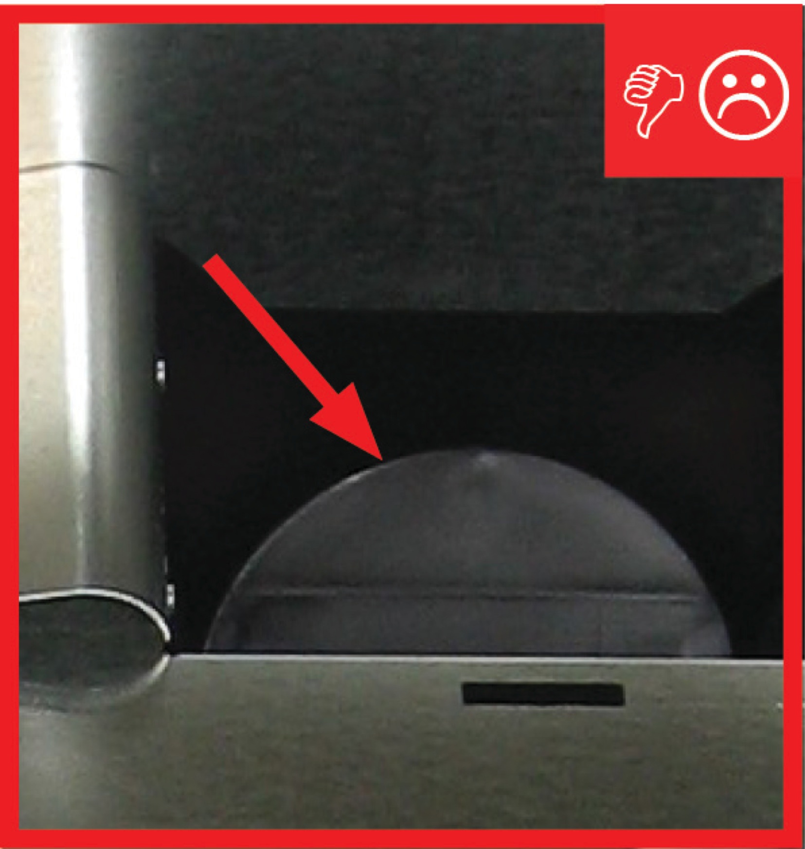
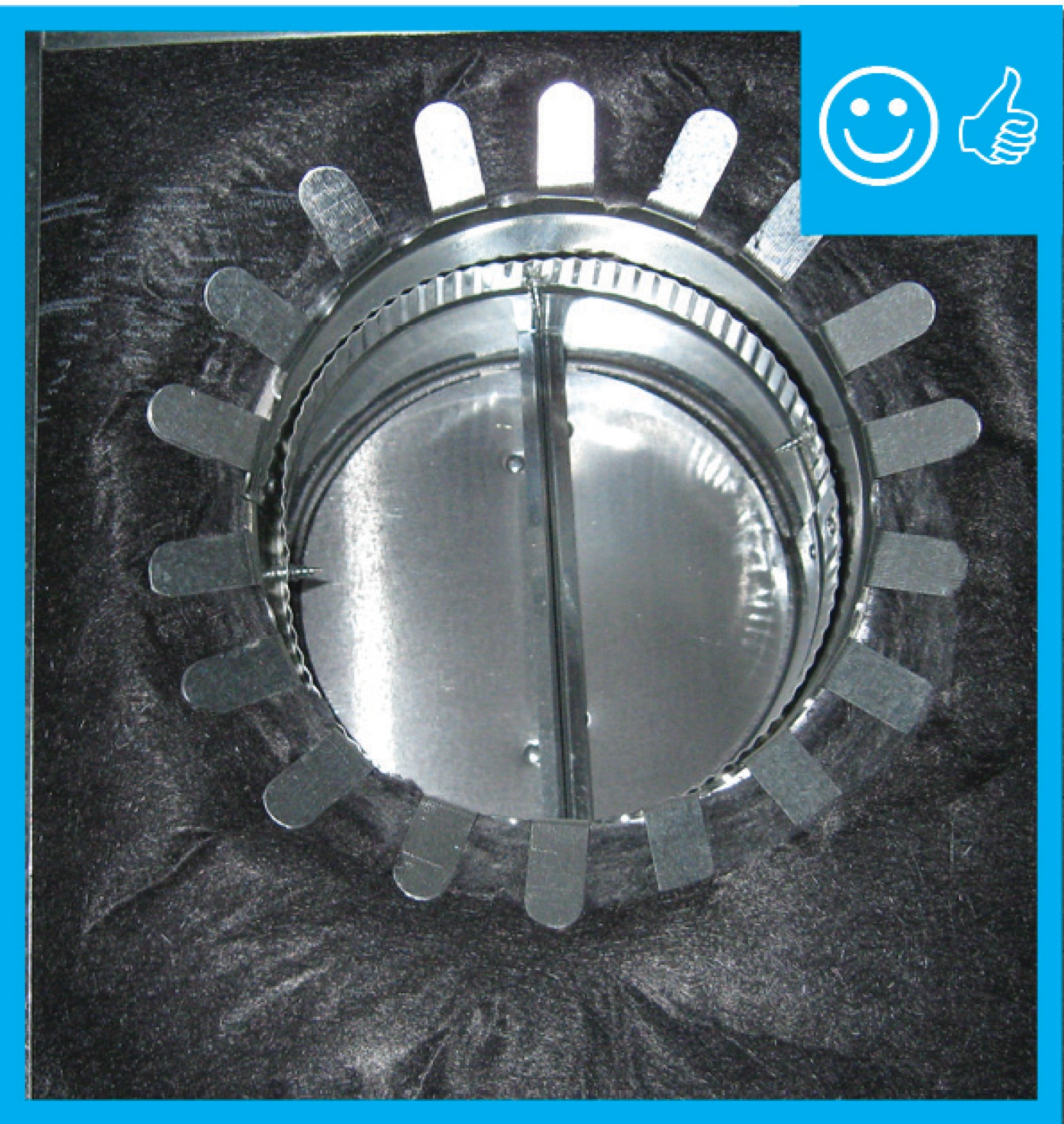
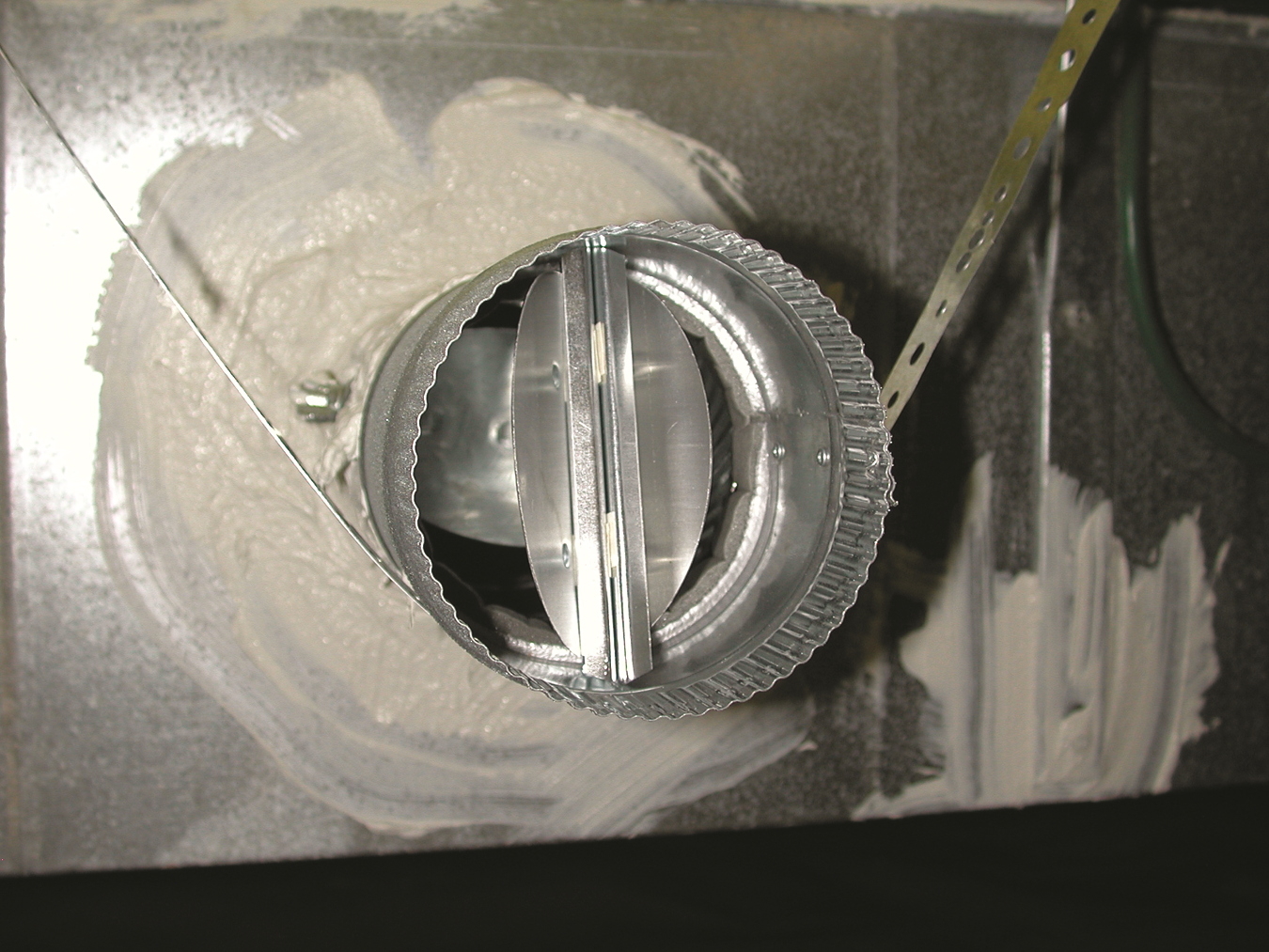
Back-draft damper still has a piece of tape that prevented it from rattling during shipping
Image
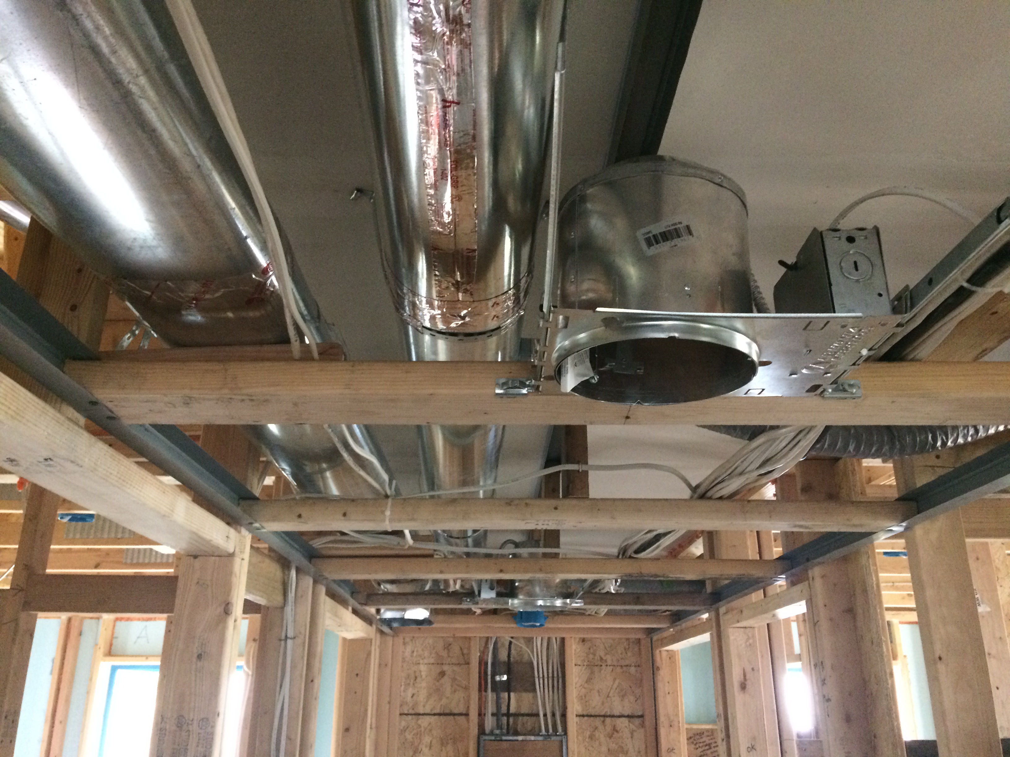
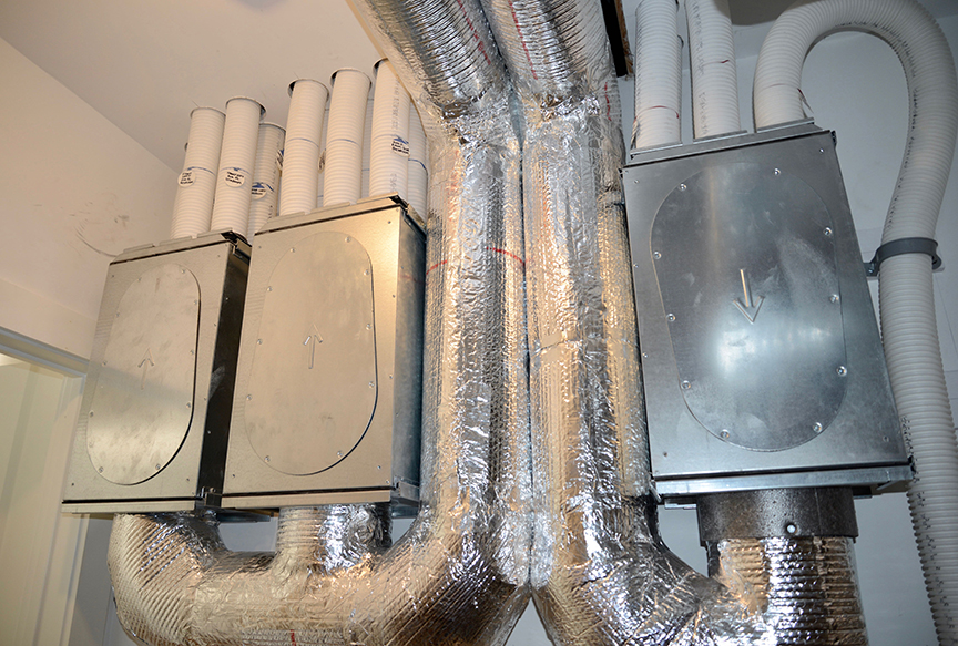
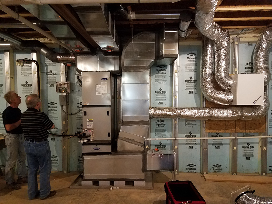
Because this ICF and spray foamed house is so well insulated, the HVAC system is smaller, the round metal ducts are smaller diameter, and the duct layout is more compact.
Image
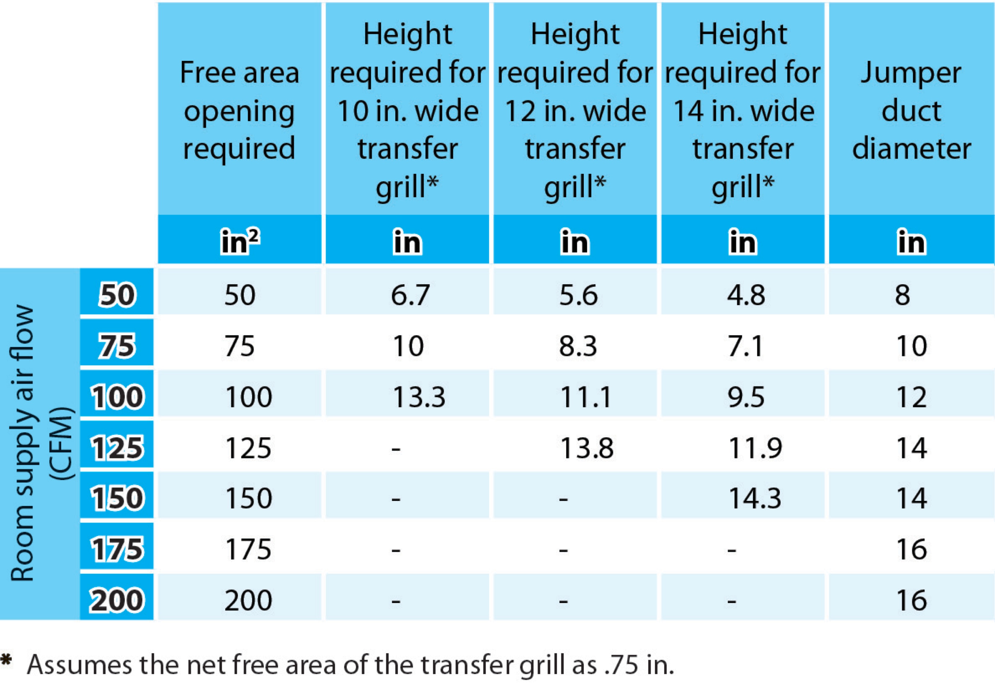
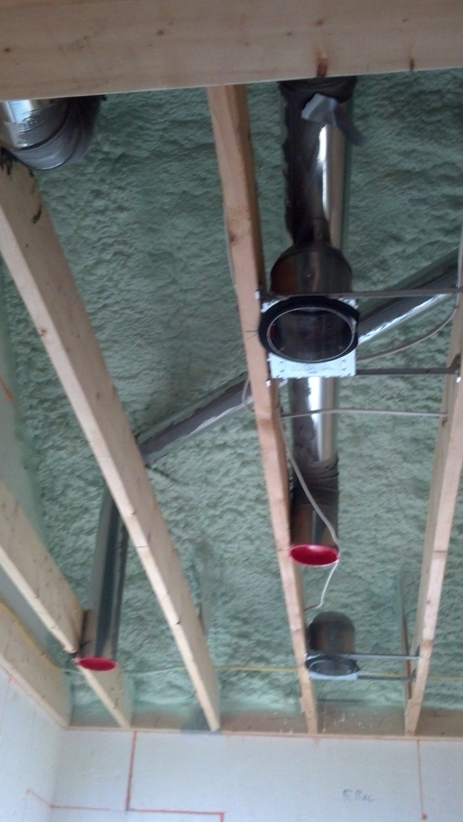
Bedrooms pressure-balanced and provide 1 sq. in. of free area opening per 1 CFM of supply air or achieve a Rater-measured pressure differential ≤ 3 Pa
Image

Bedrooms pressure-balanced and provide 1 sq. in. of free area opening per 1 CFM of supply air or achieve a Rater-measured pressure differential ≤ 3 Pa
Image
Image
Image

Image
Image
Image
Image
Image
Building cavities not used as supply or return ducts unless they meet Items 3.2, 3.3, 4.1, and 4.2 of this Checklist
Image
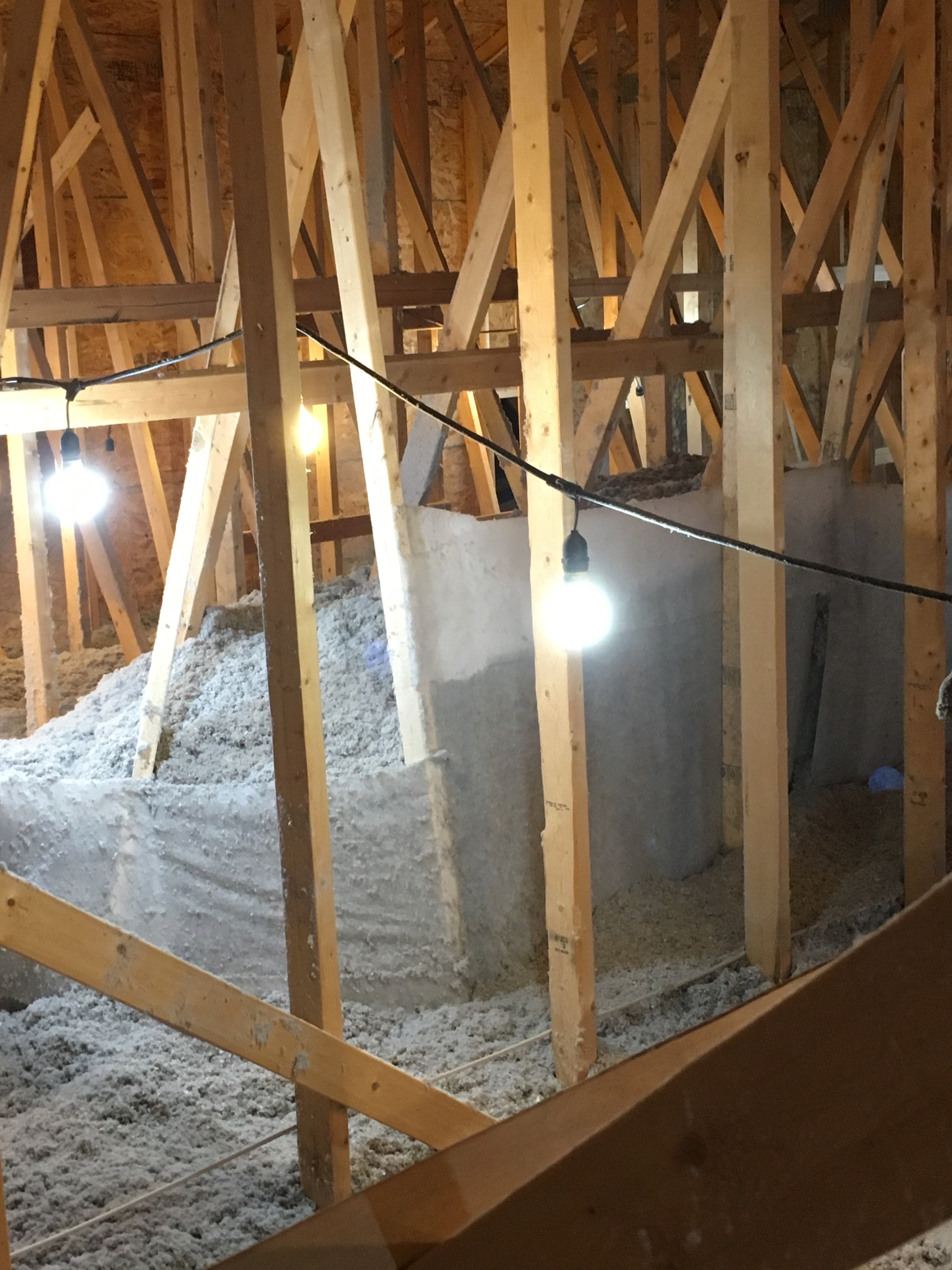
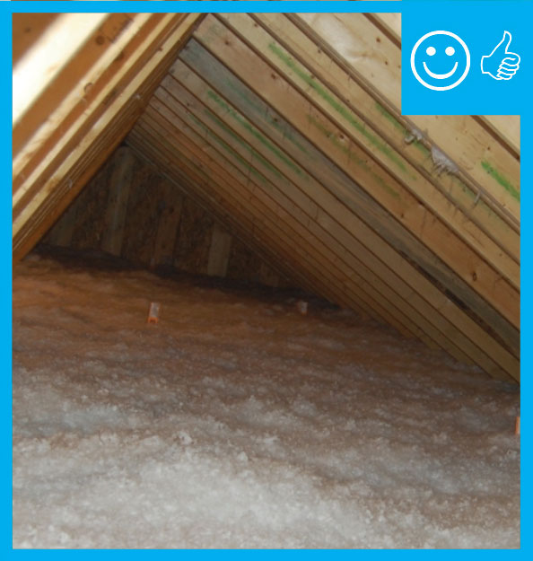
Buried ducts are laid on the floor of a vented attic then covered with spray foam and blown attic floor insulation
Image
Image
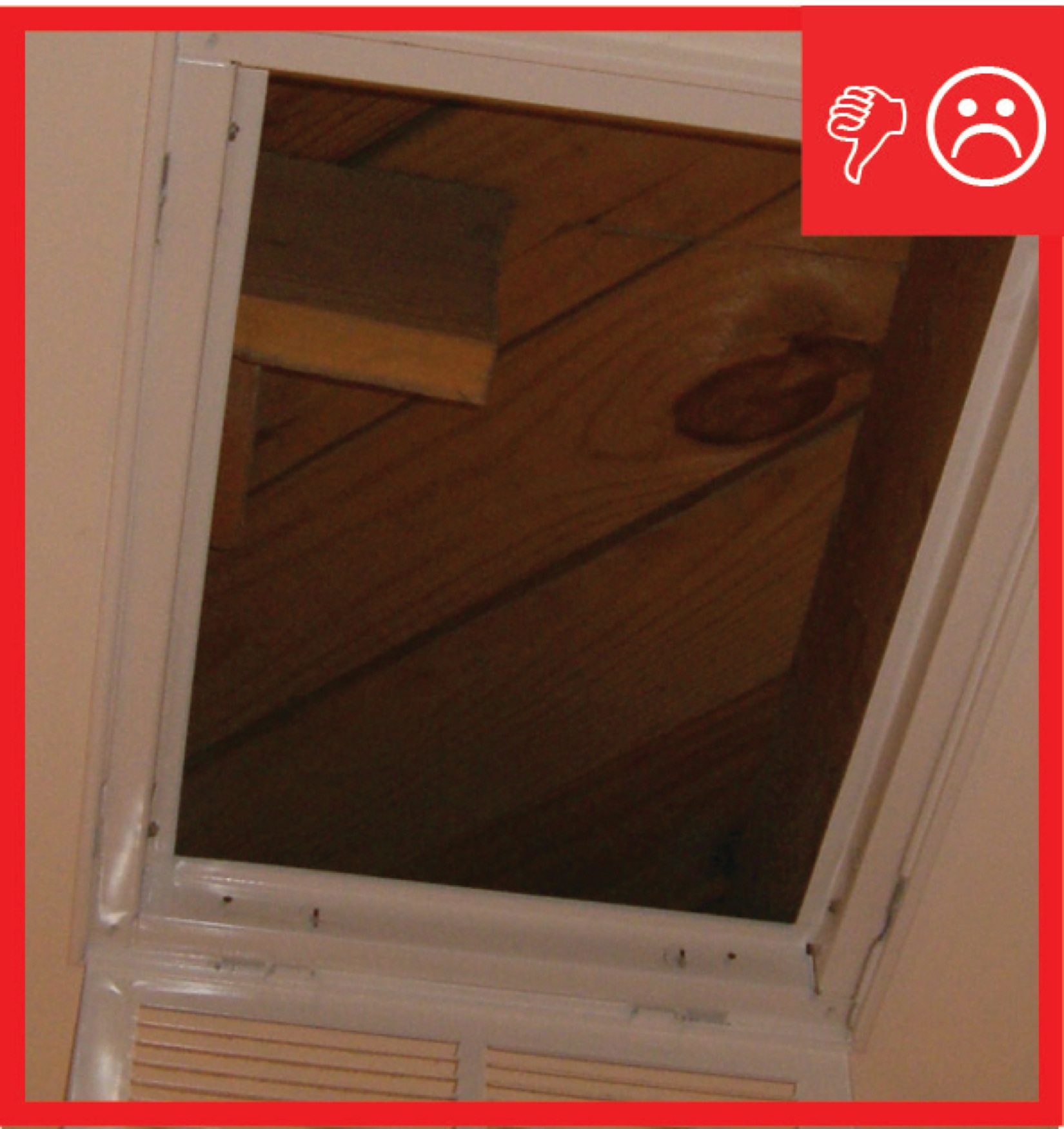
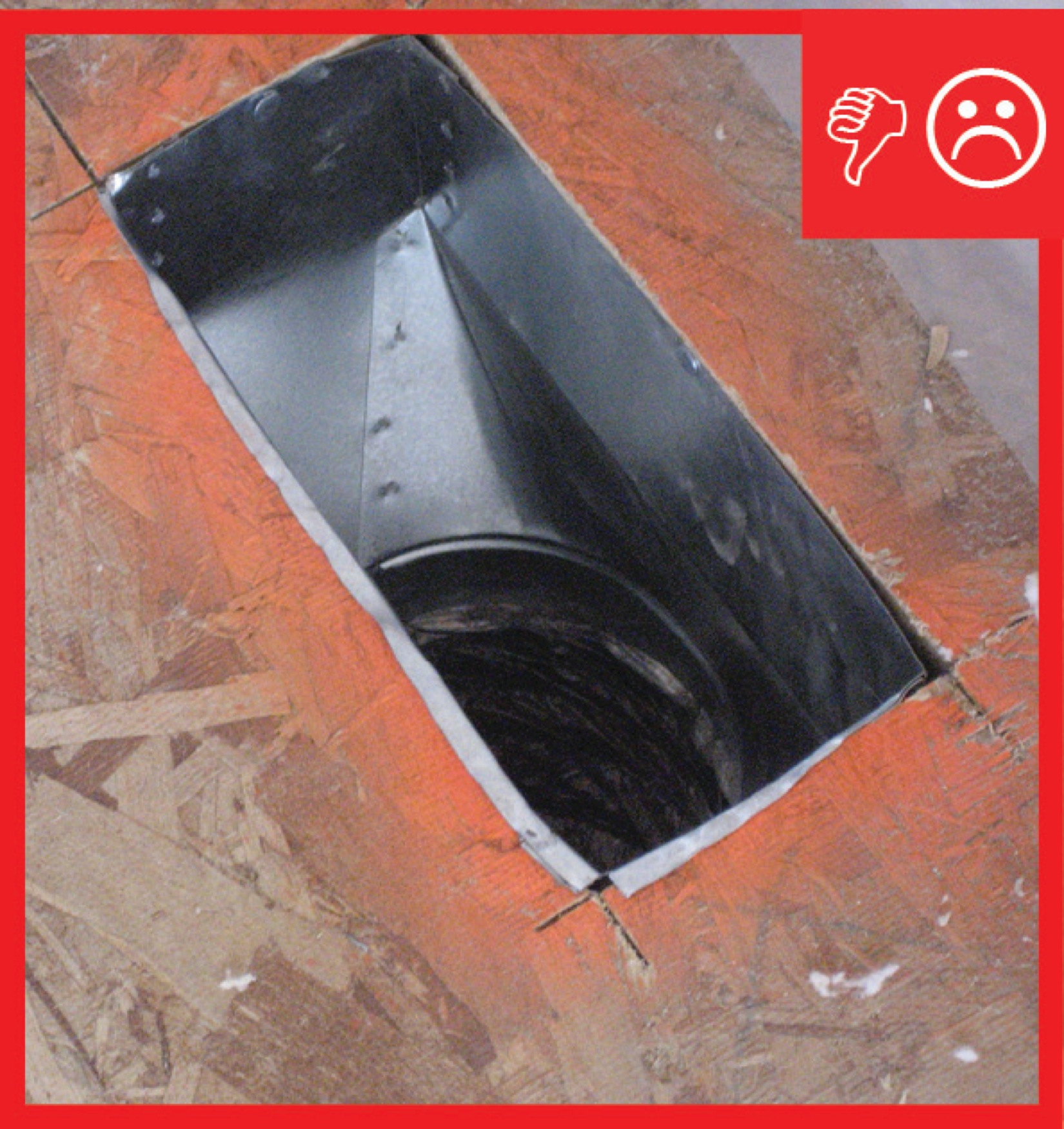
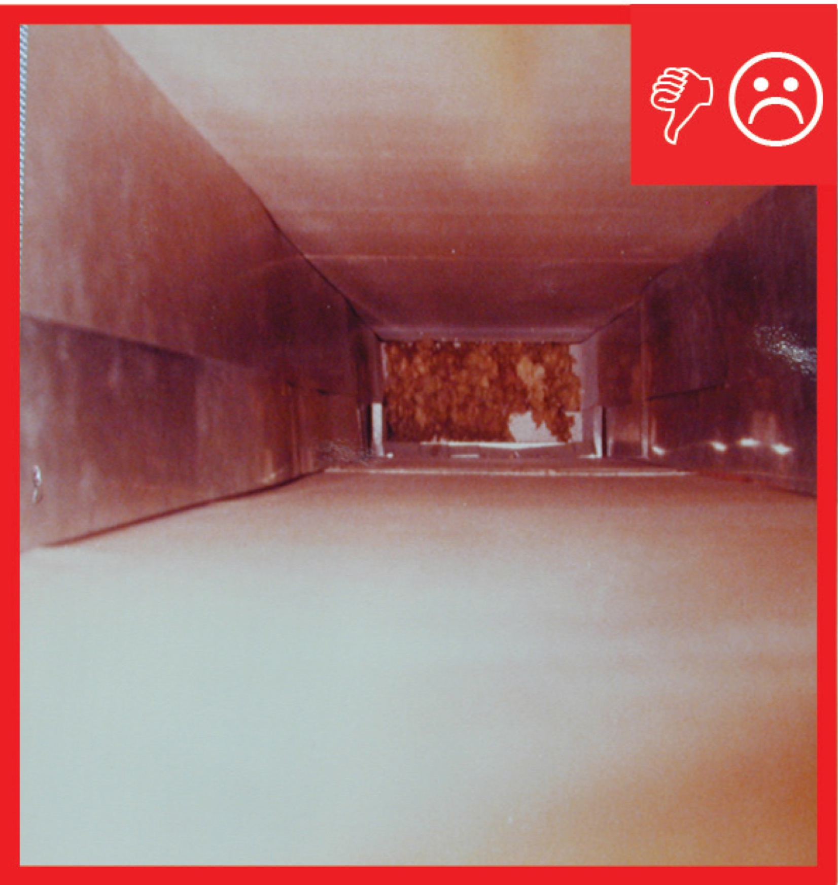
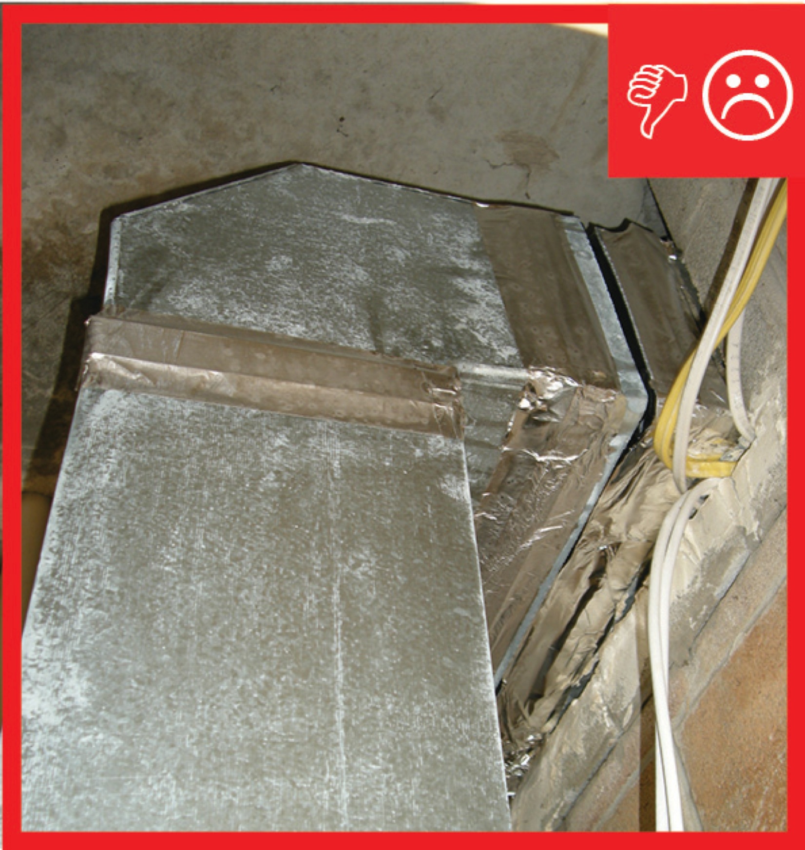
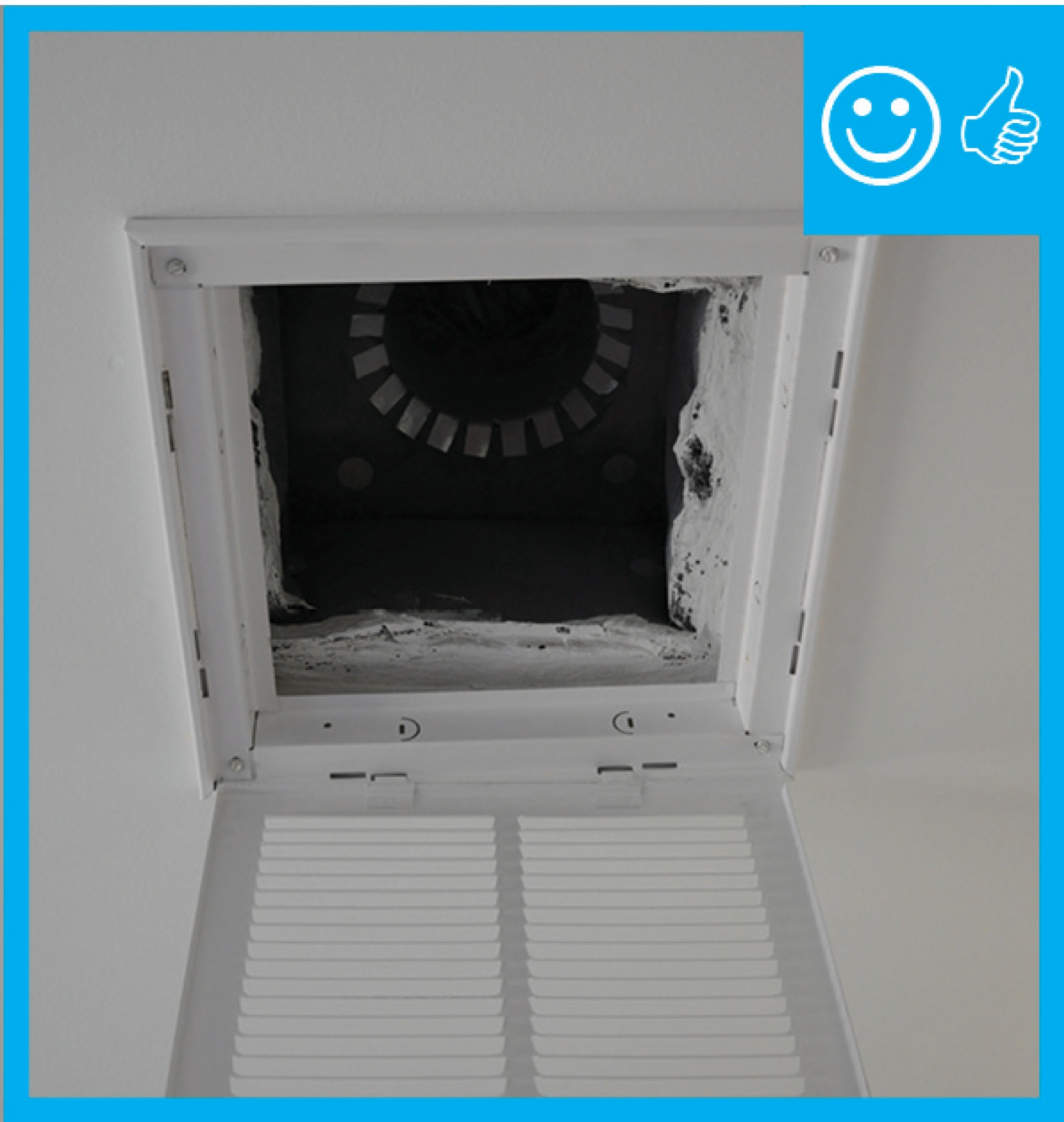
Cavity used for return is not insulated and is not air sealed, which will pull in air from outside
Image
Image
Image
Image
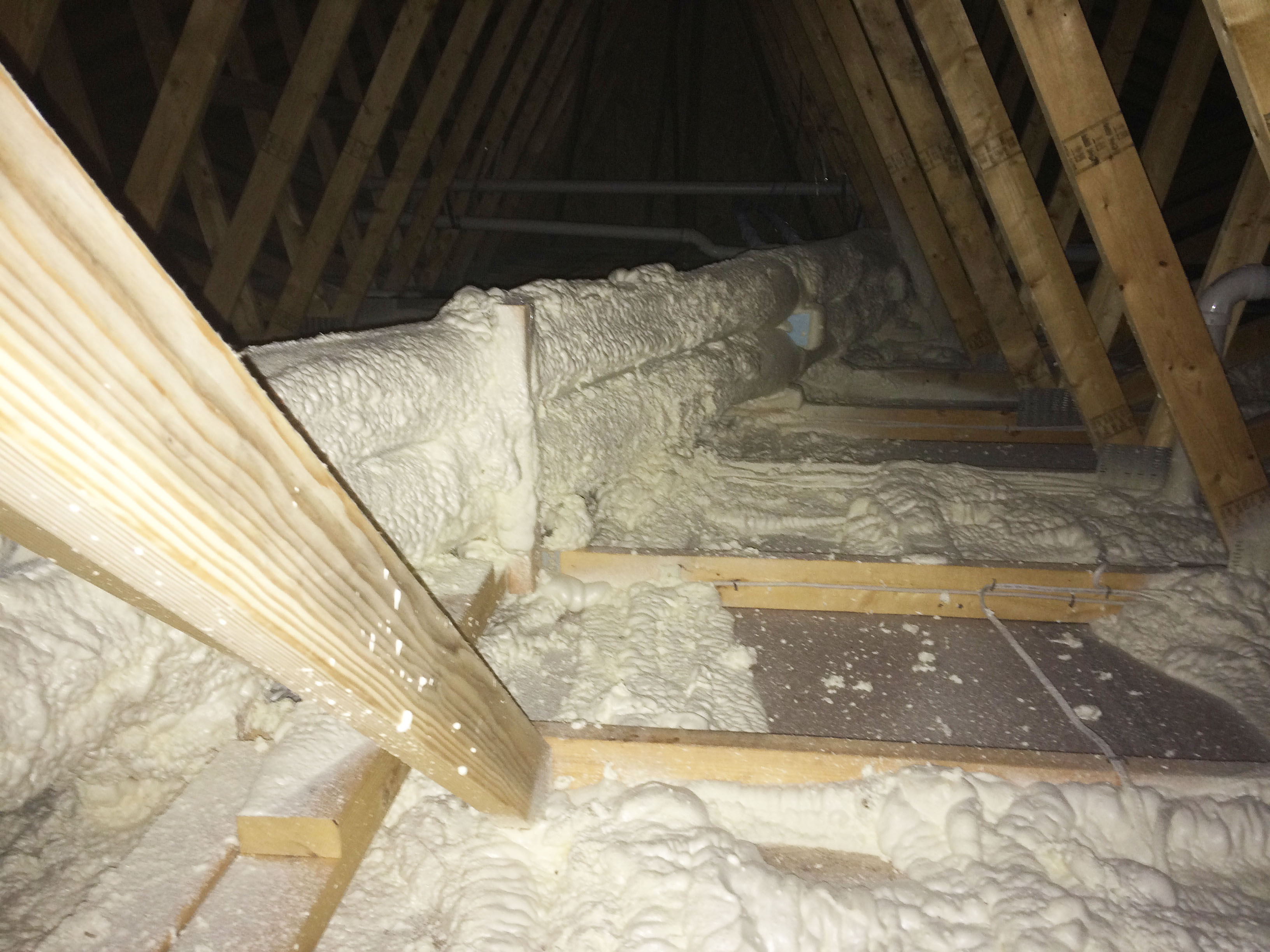
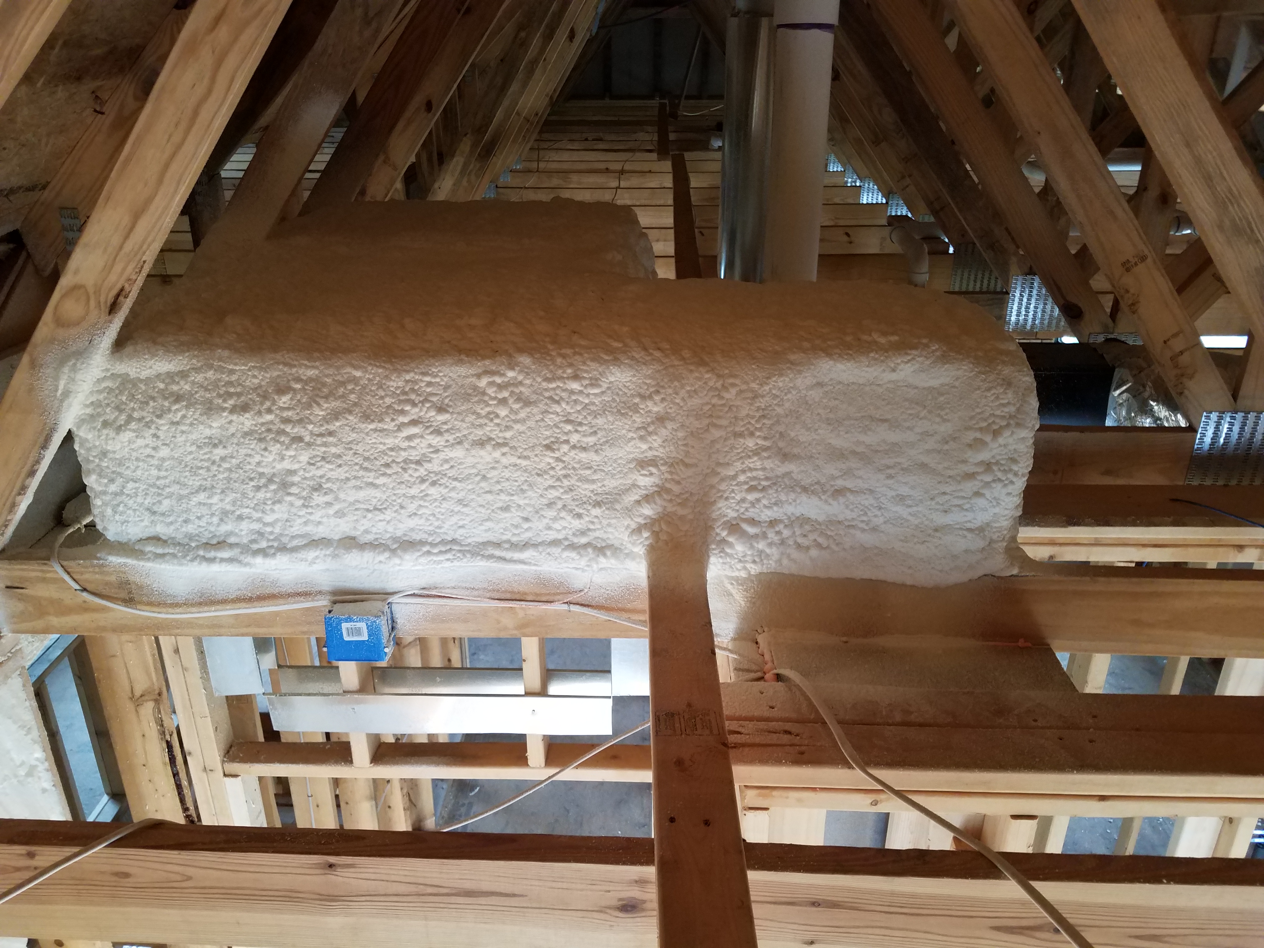
Closed-cell spray foam covers the heat recovery ventilator ducts and also seals all top plates and seams in the ceiling drywall of the vented attic.
Image
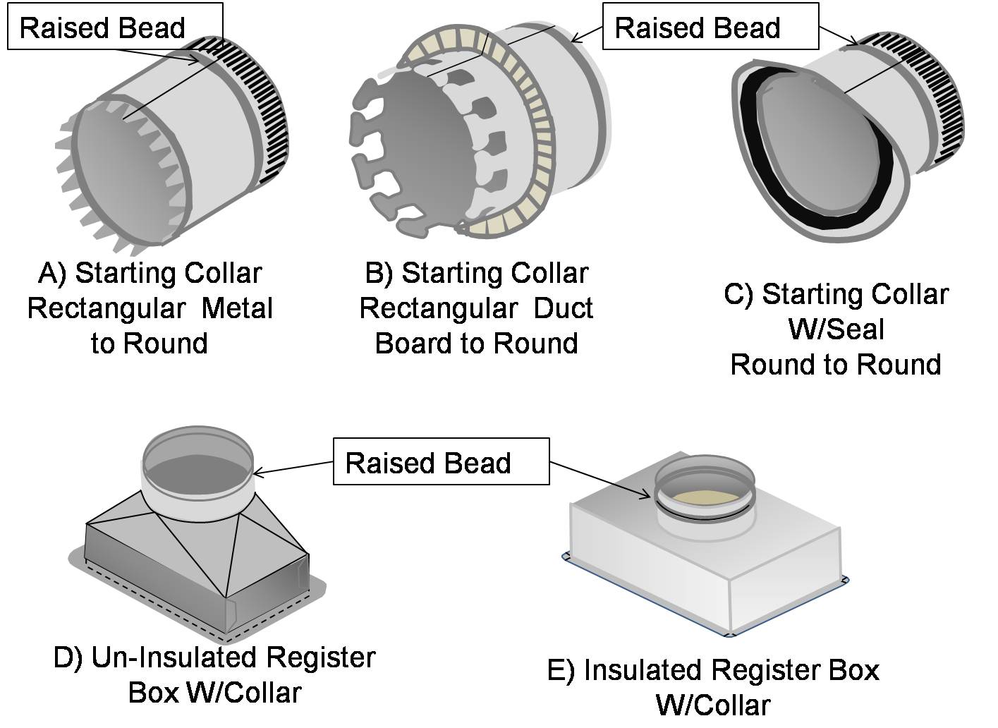
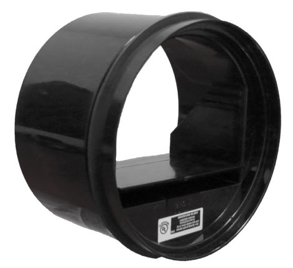
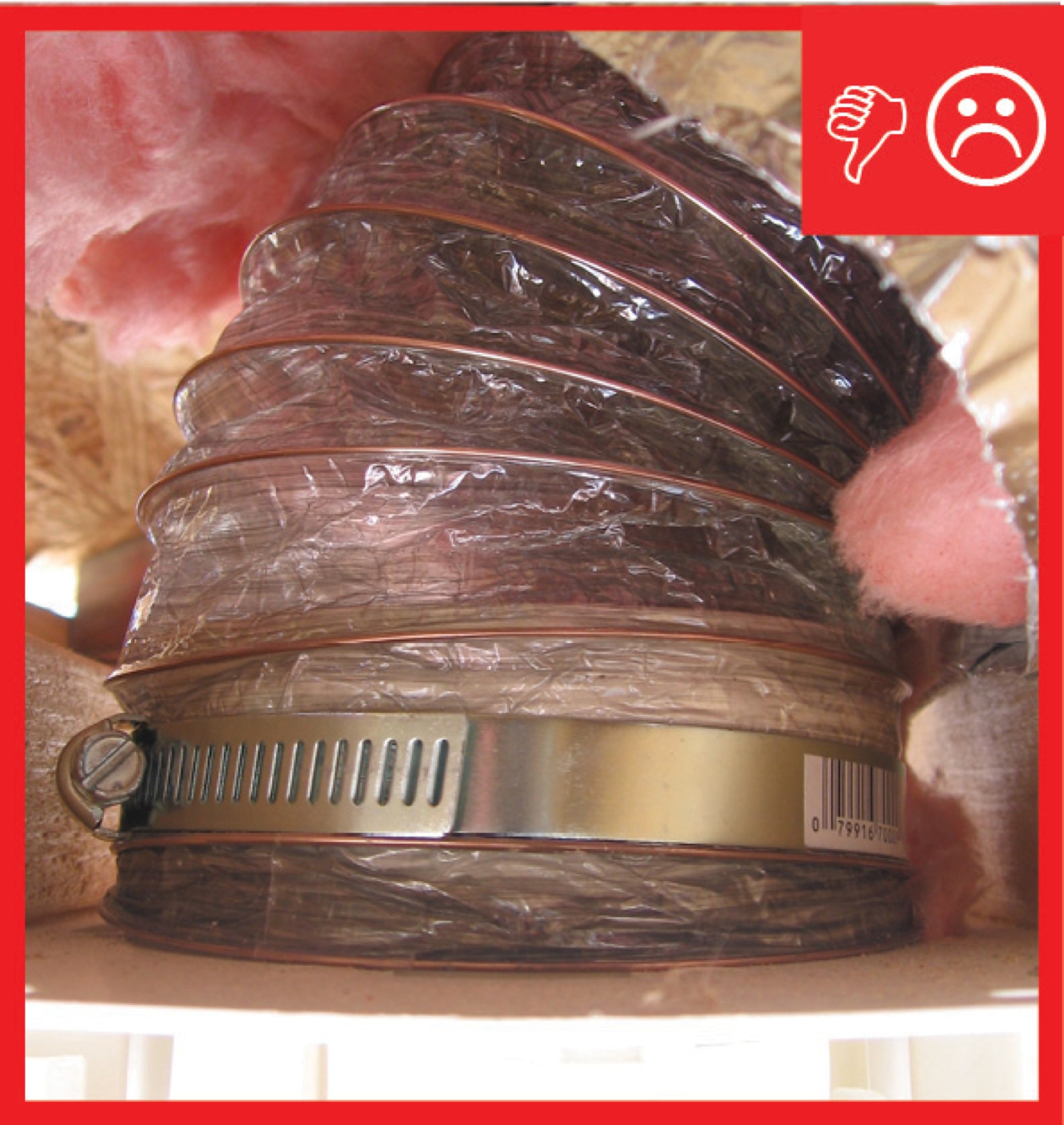
Collars that are specifically made for flexible duct have a raised bead to prevent the duct from slipping off
Image

Image
Image
Image
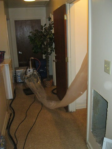
Connect the plastic application tunnel from the injection equipment to the supply plenum.
Image
Image
Image

Consider using a metal duct elbow instead of flex duct at boot connections to prevent compressions
Image
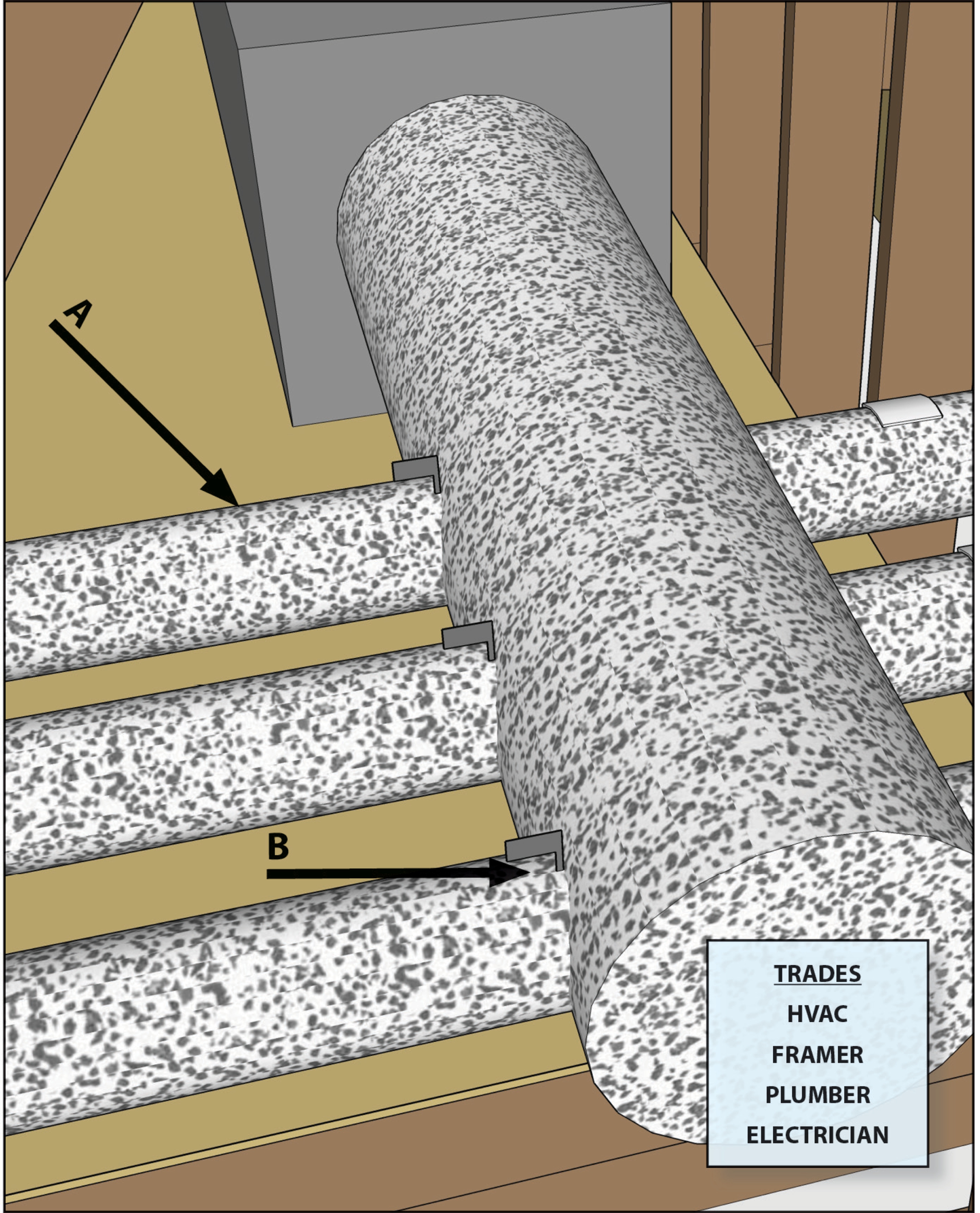
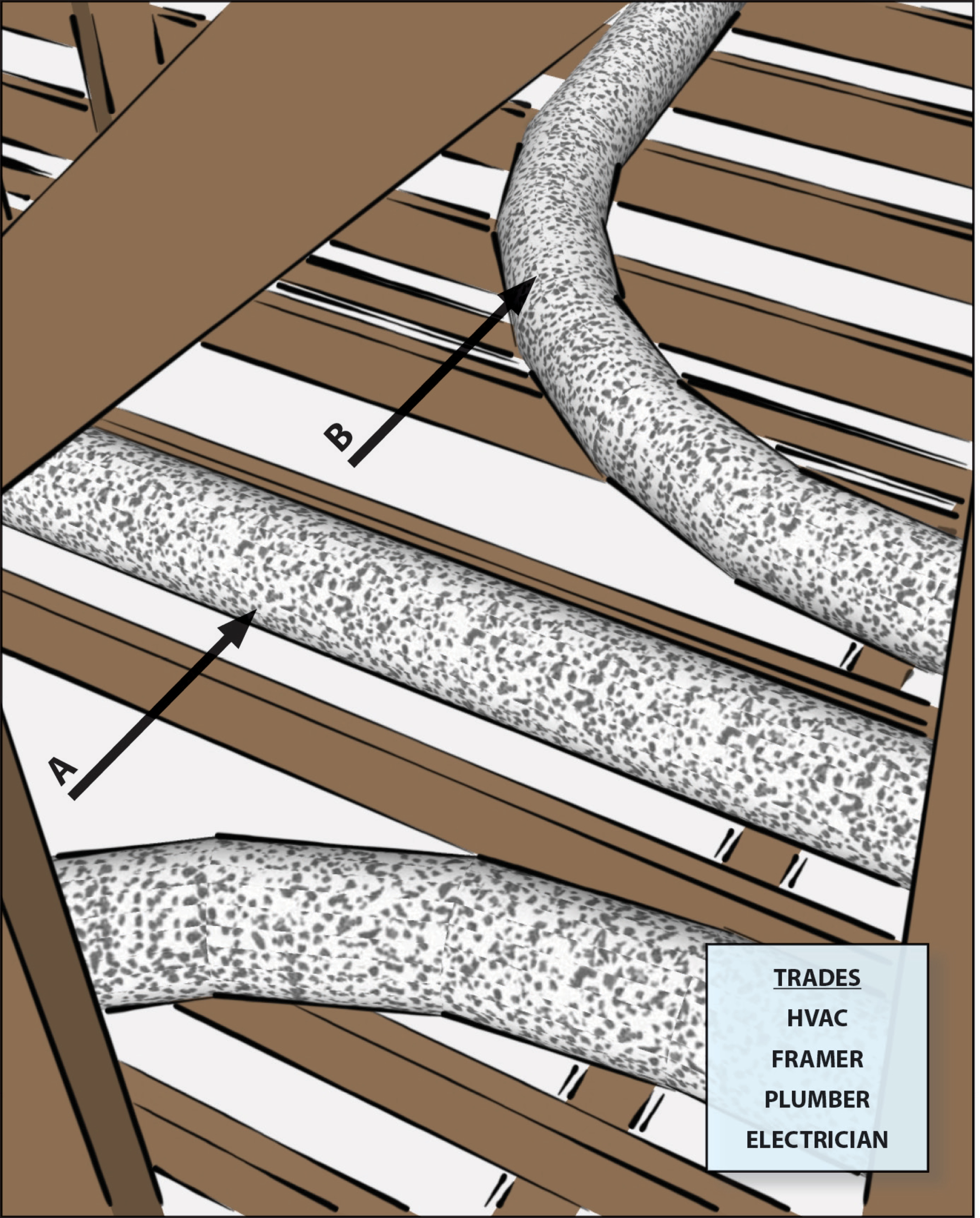
Coordinate with other trades including framers, plumbers, and electricians to prevent needless looping of flex duct
Image
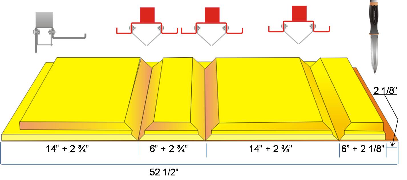
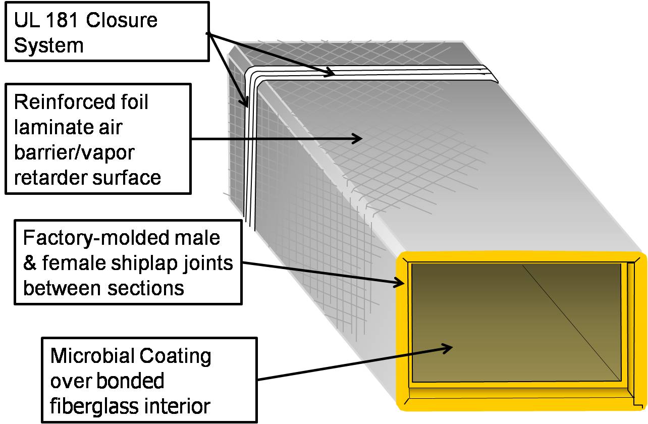
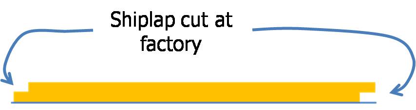
Cut fiber board with a red V-groove tool and a gray shiplap tool to create mitered corners and a shiplapped edge for duct sections
Image
Image
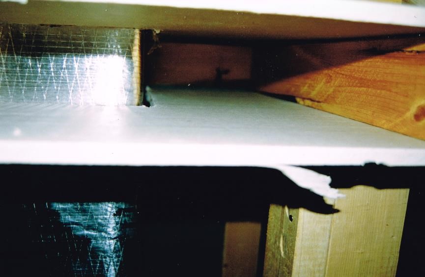
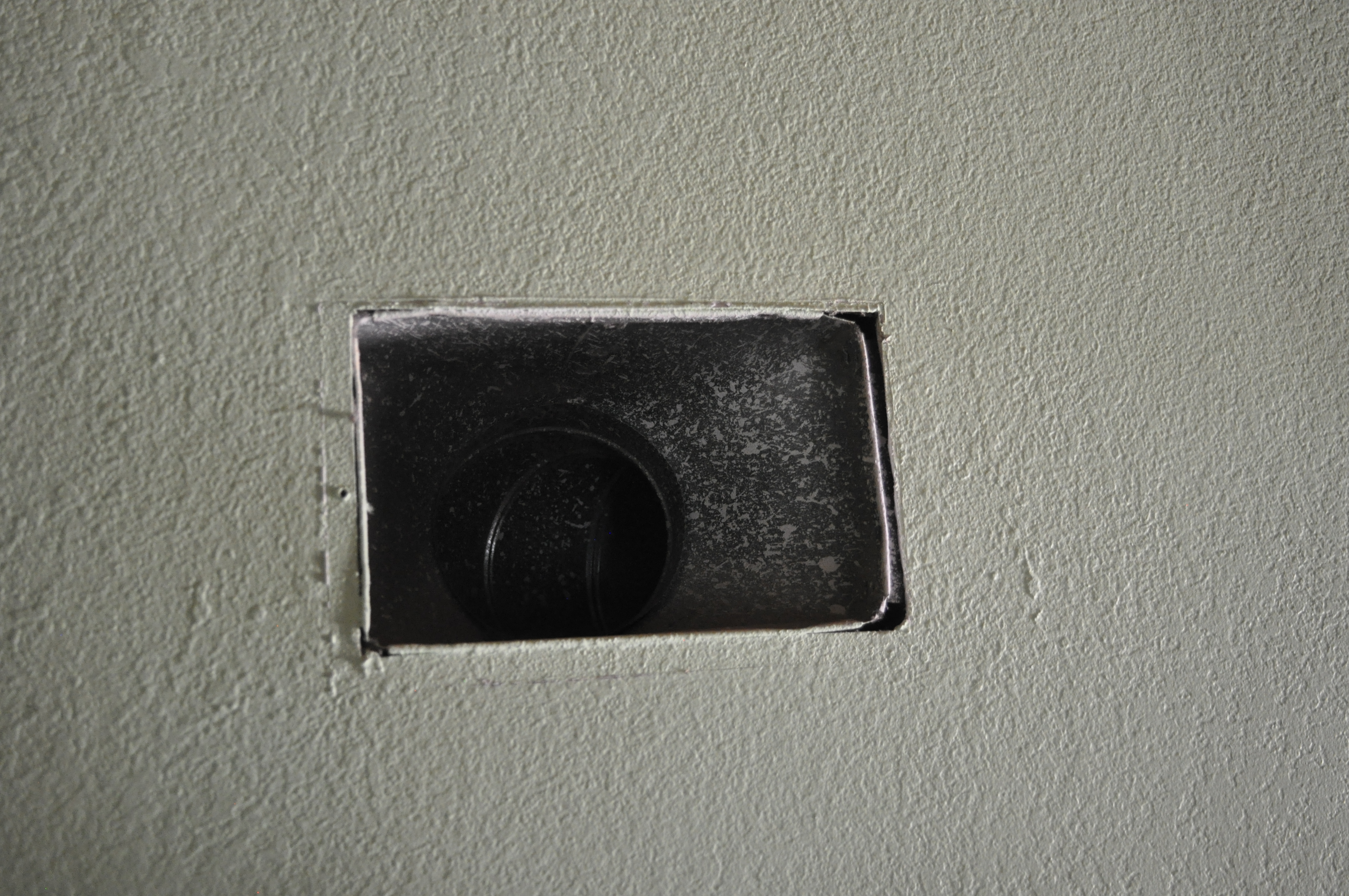
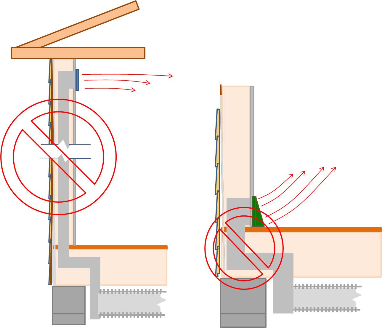
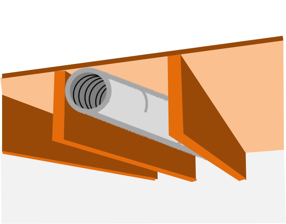
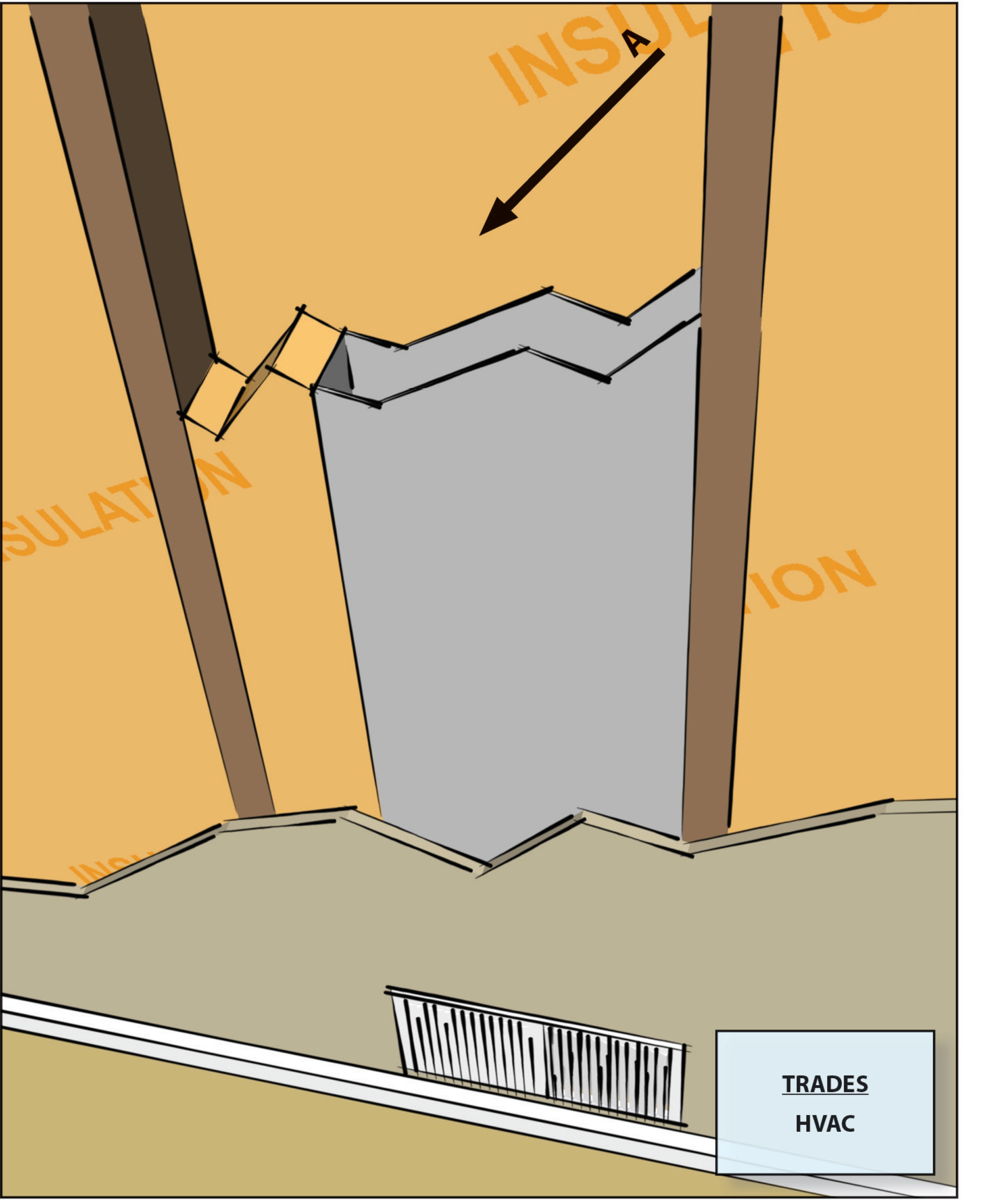
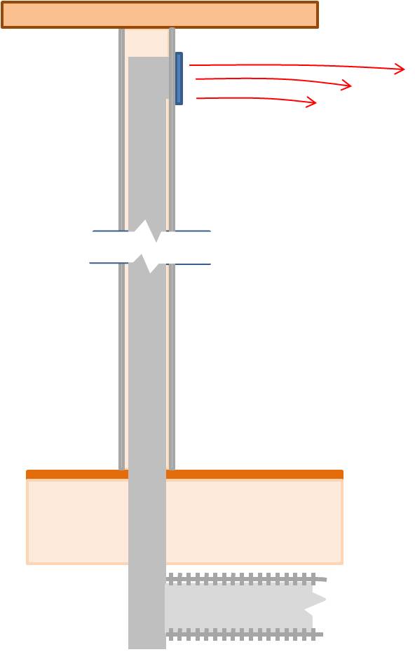
Cut-away view showing unsealed gaps around a heating duct that goes through a wall
Image
Image
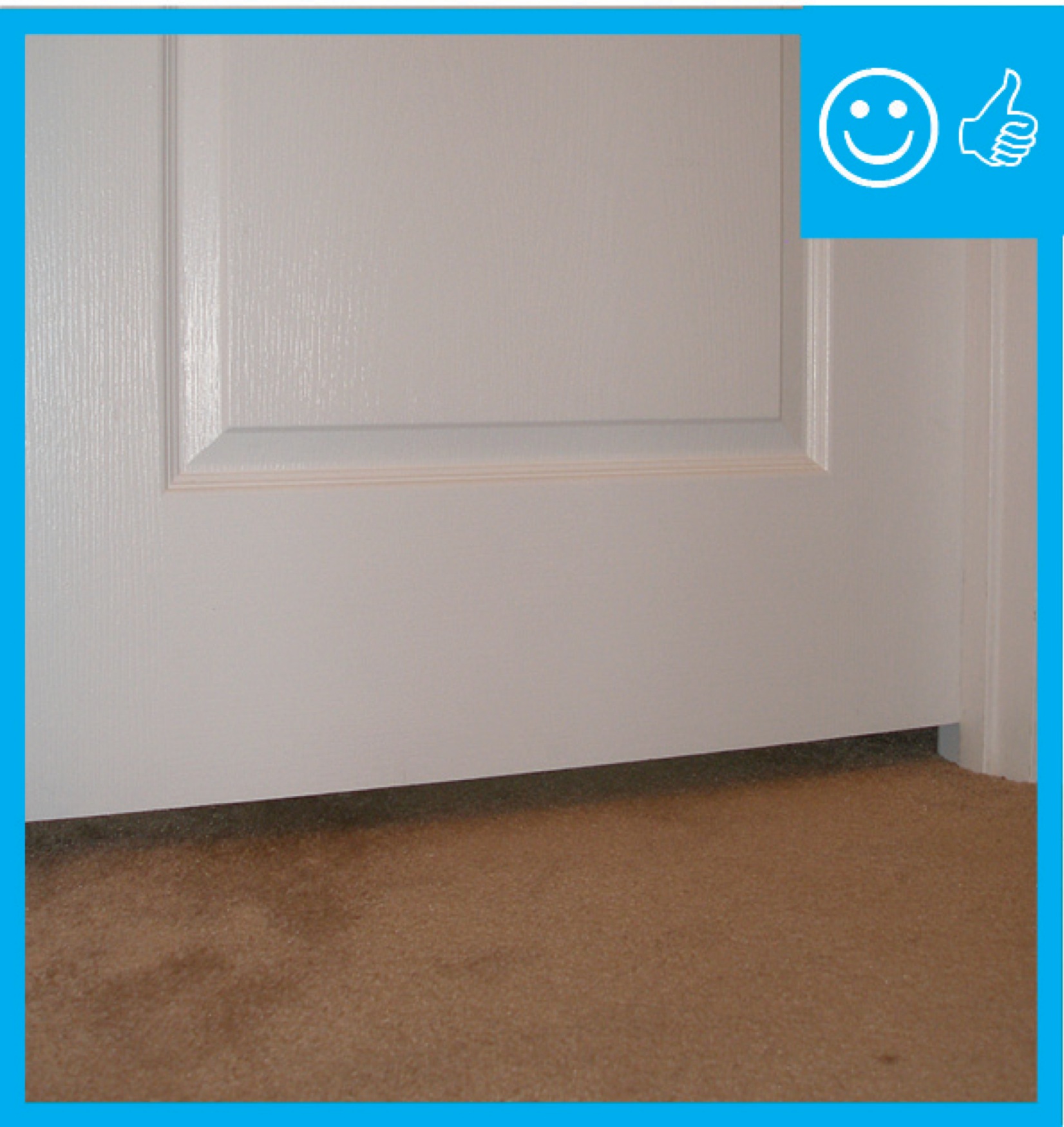
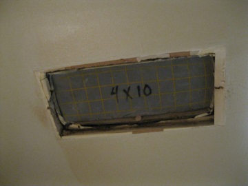
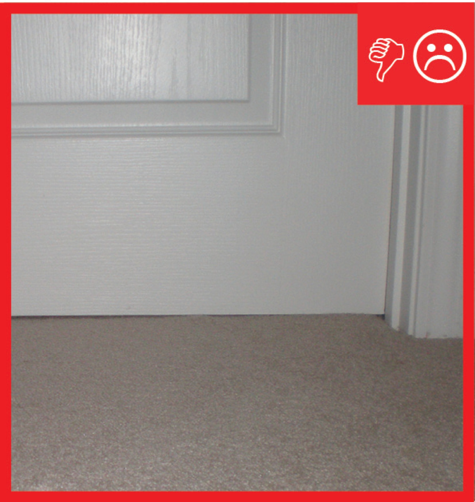
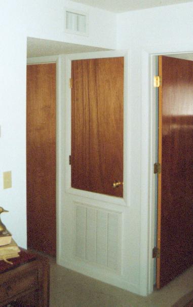
Door has been undercut to allow for specified amount of air flow therefore contributing to pressure balancing
Image
Image
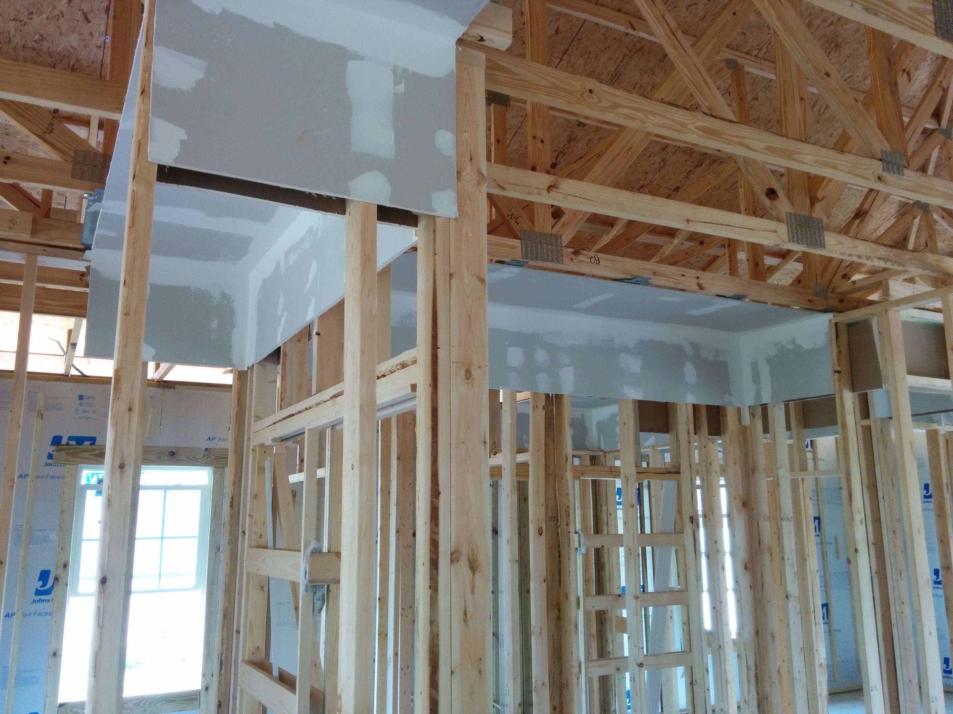
Drywall is installed before framing in dropped soffits to provide an air barrier above these duct chases.
Image
Image
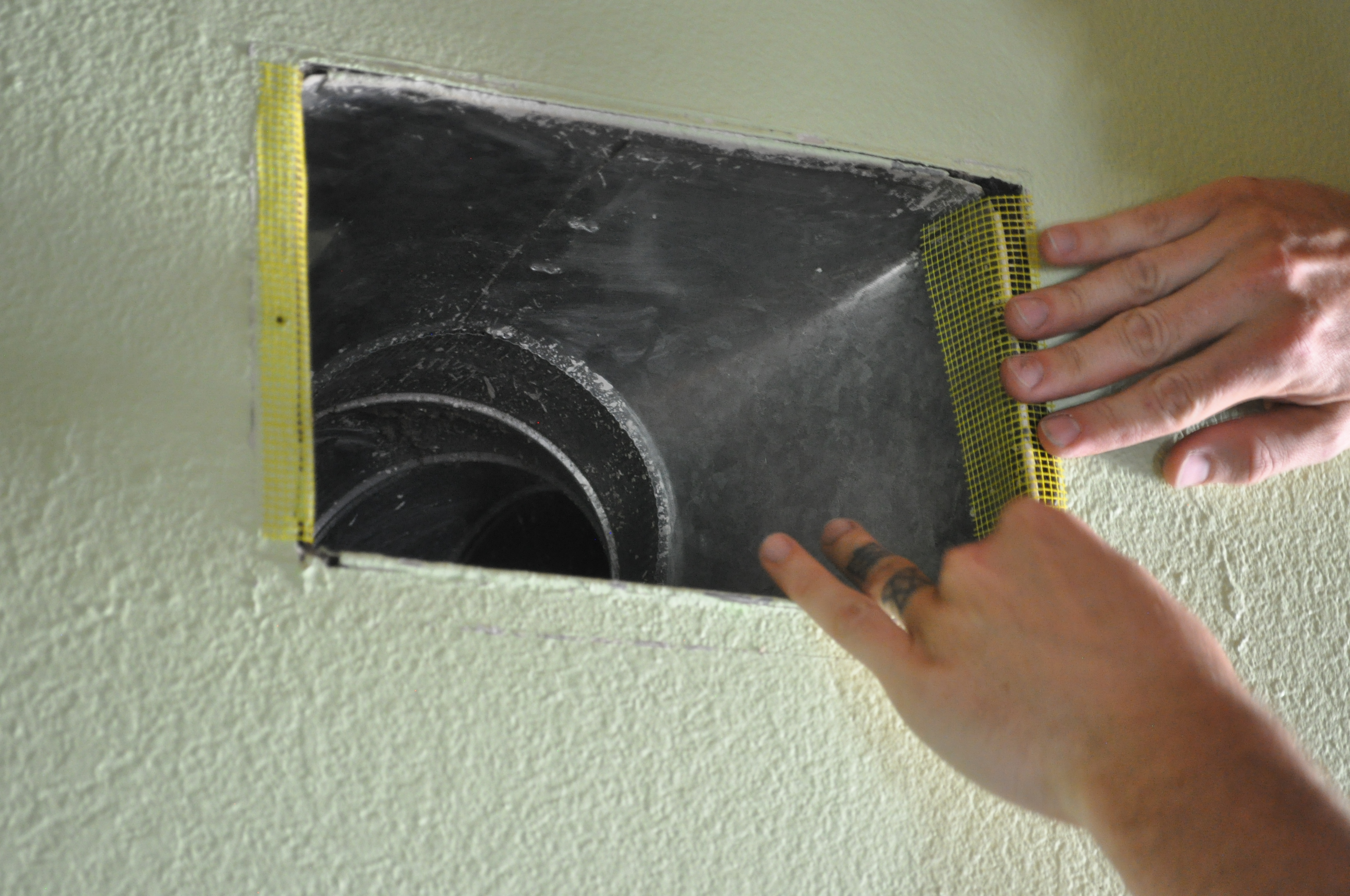
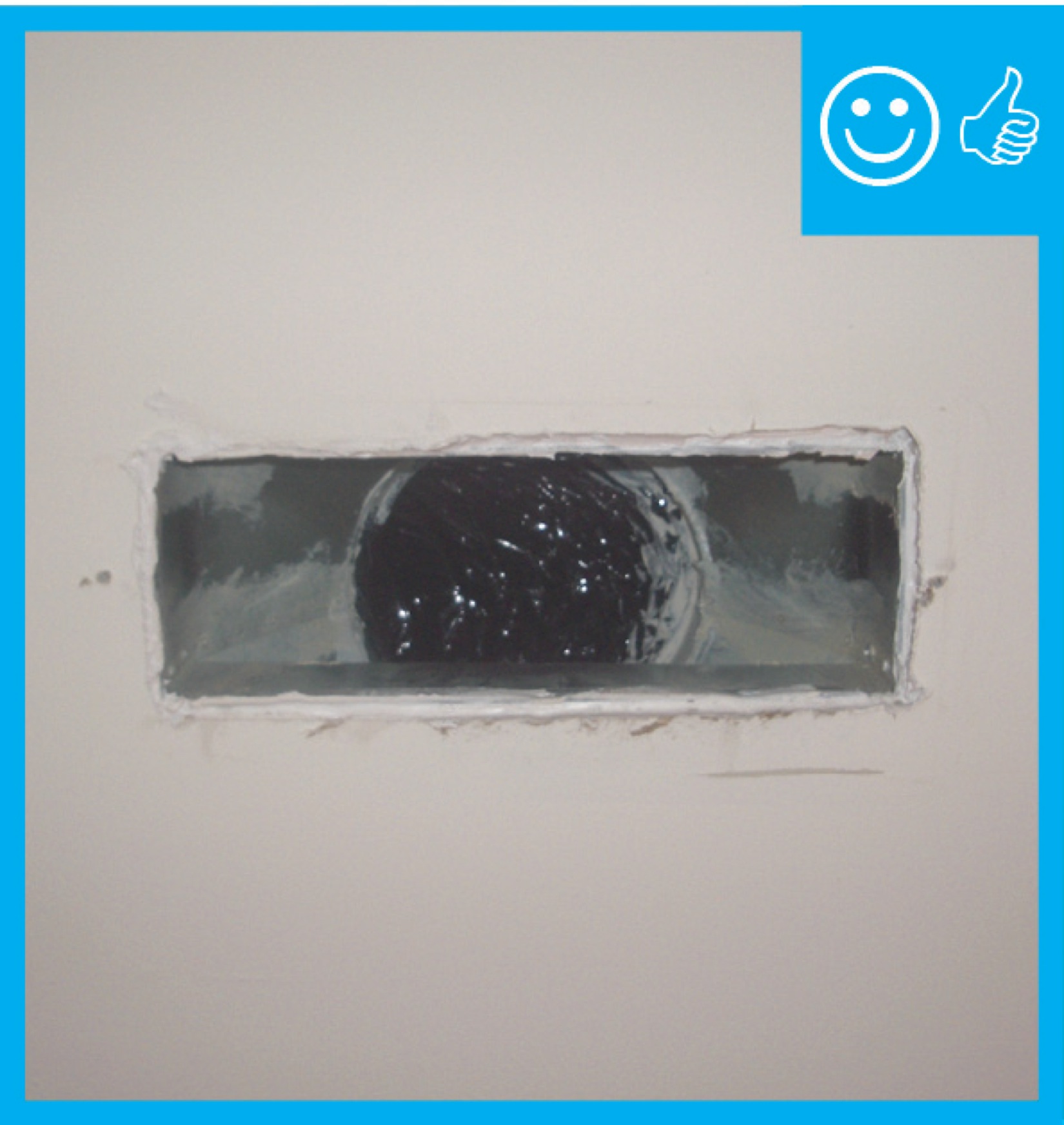
Duct boot is air sealed to ceiling by covering the seam with fiberglass mesh tape and mastic
Image
Image
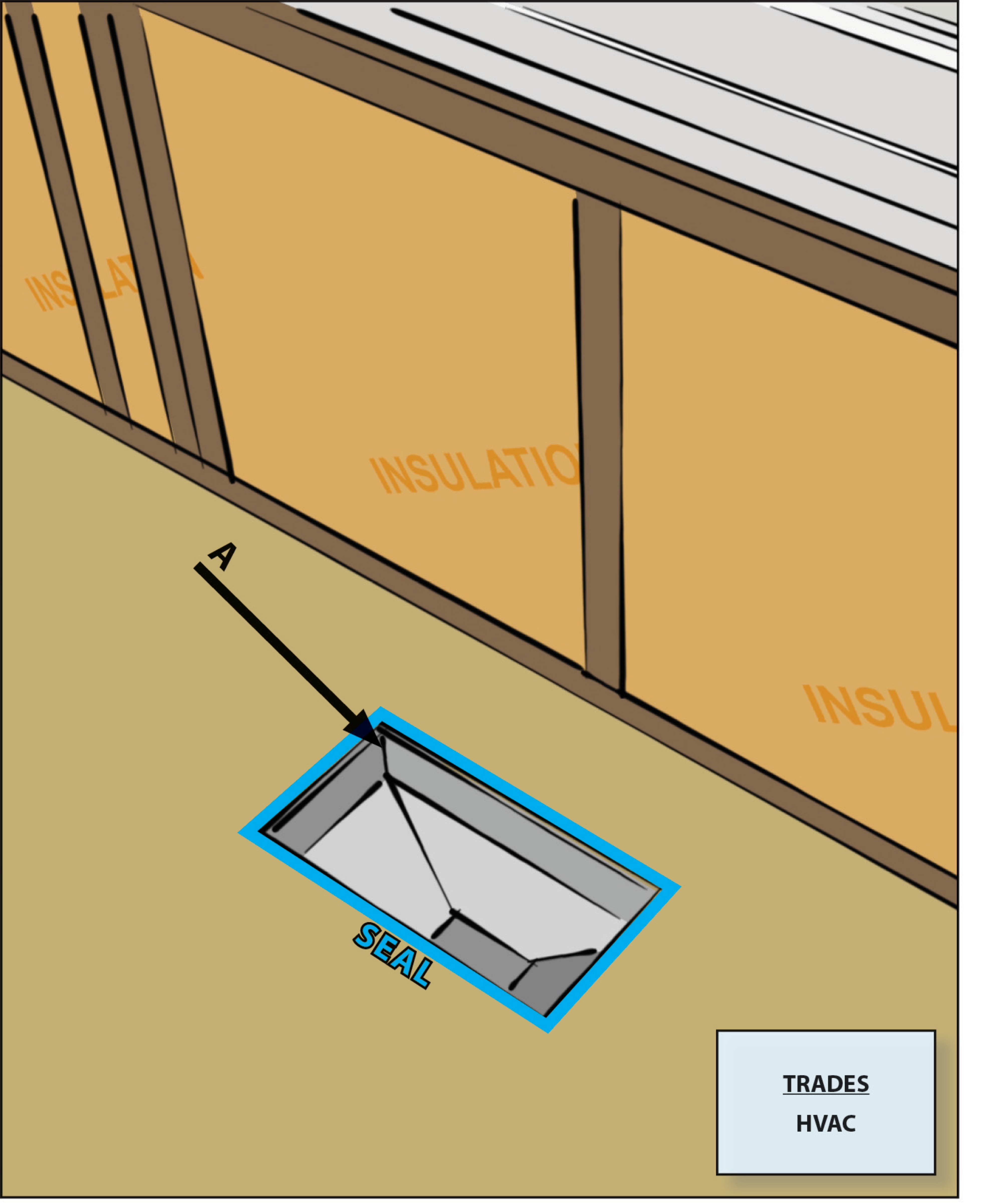
Duct boots sealed to floor, wall, or ceiling using caulk, foam, mastic tape, or mastic paste
Image
Image
Image
Image
Image
Image
Image
Image
Image
Image
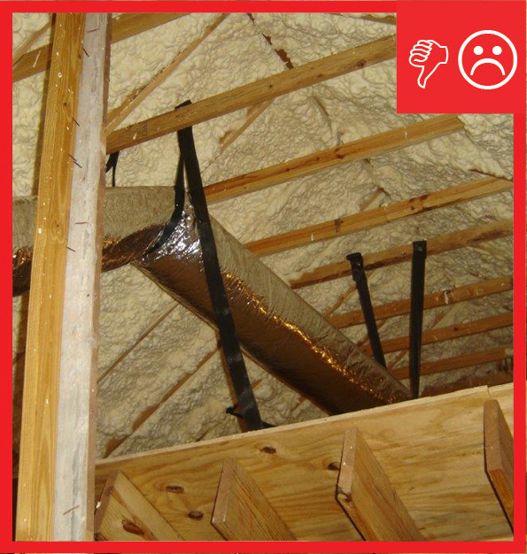
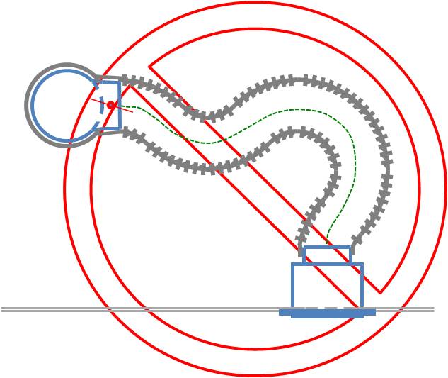
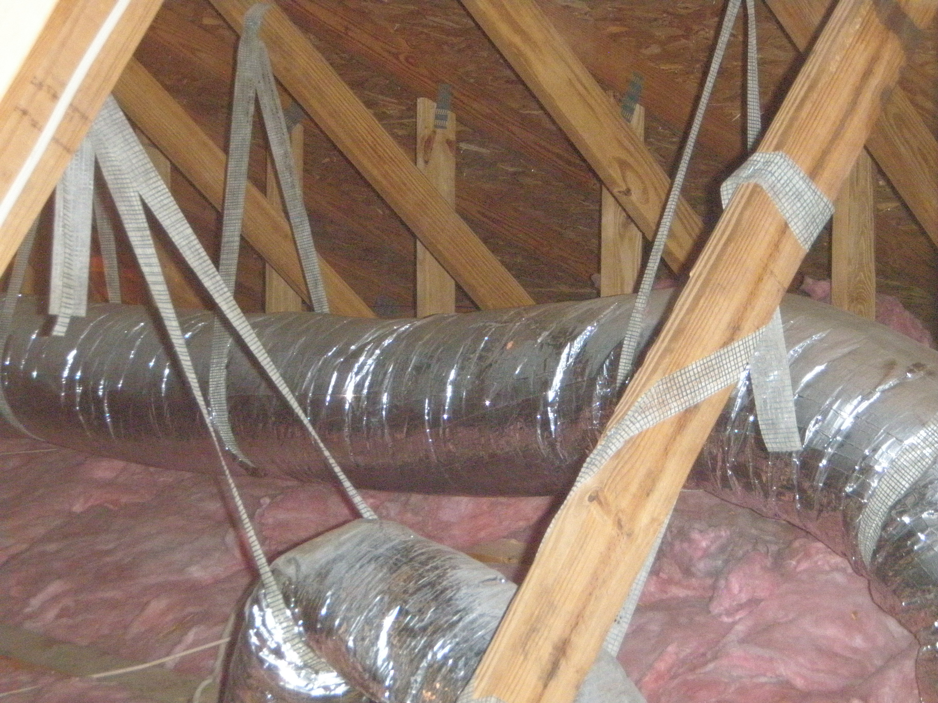
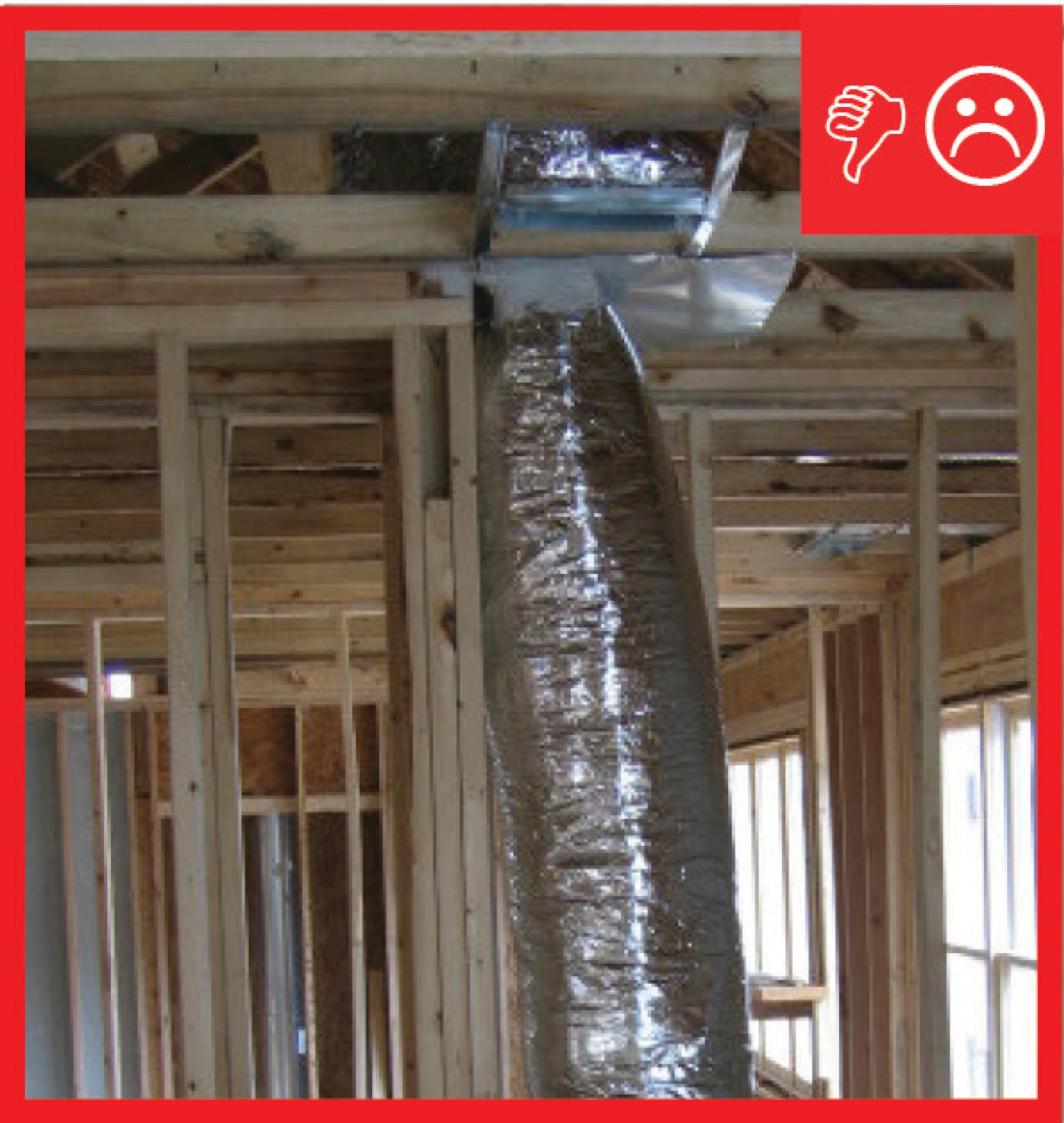
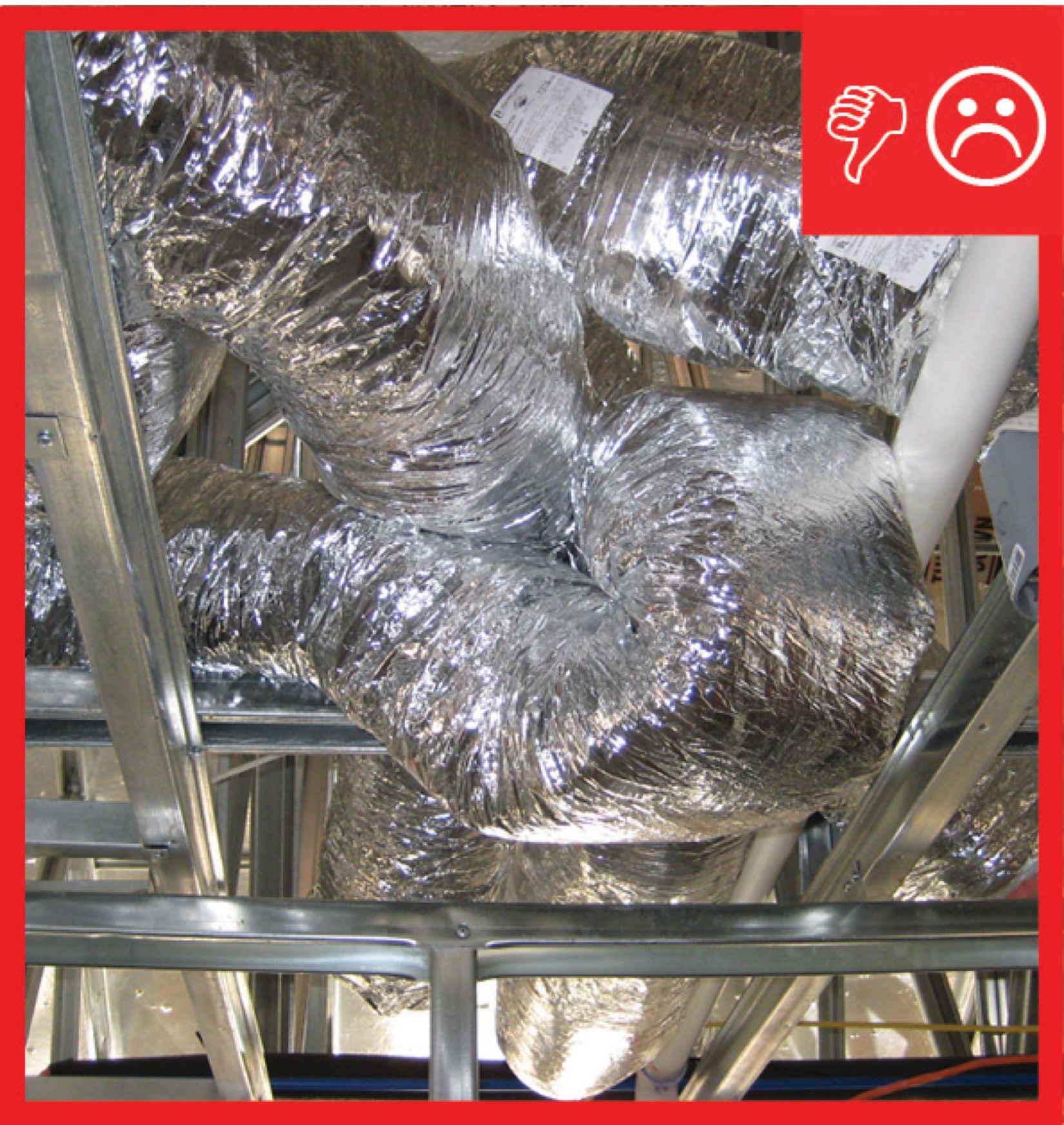
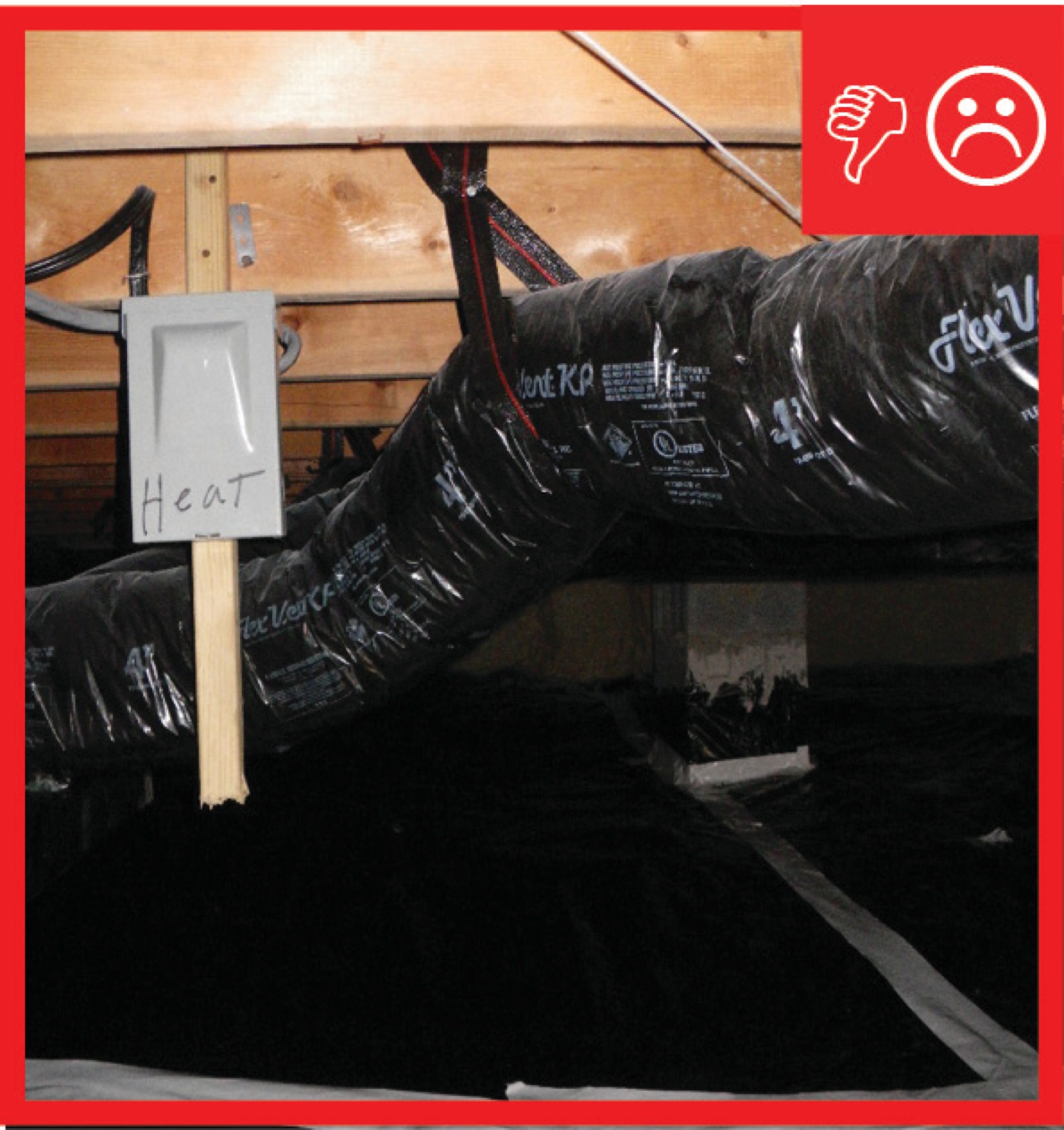
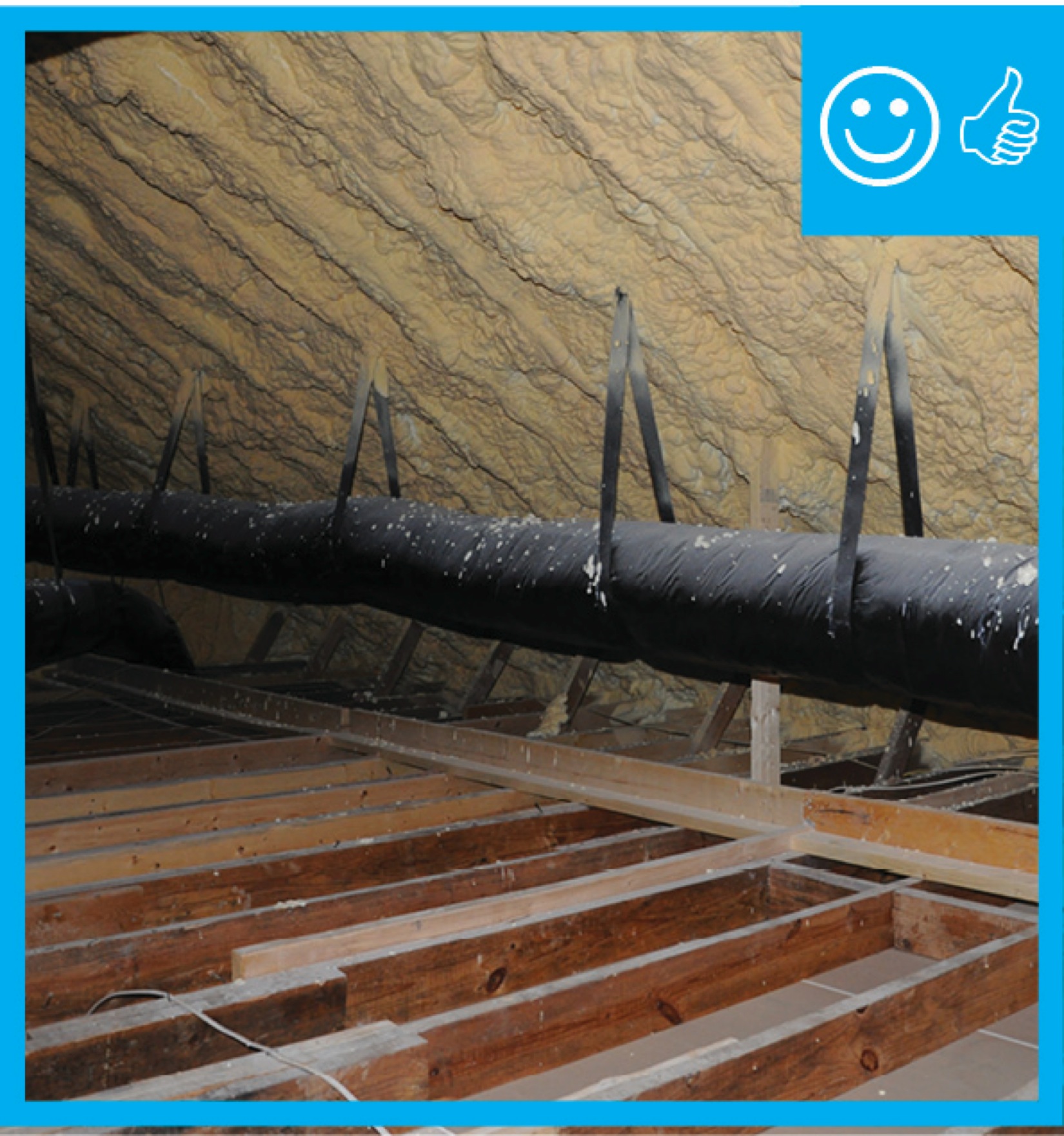
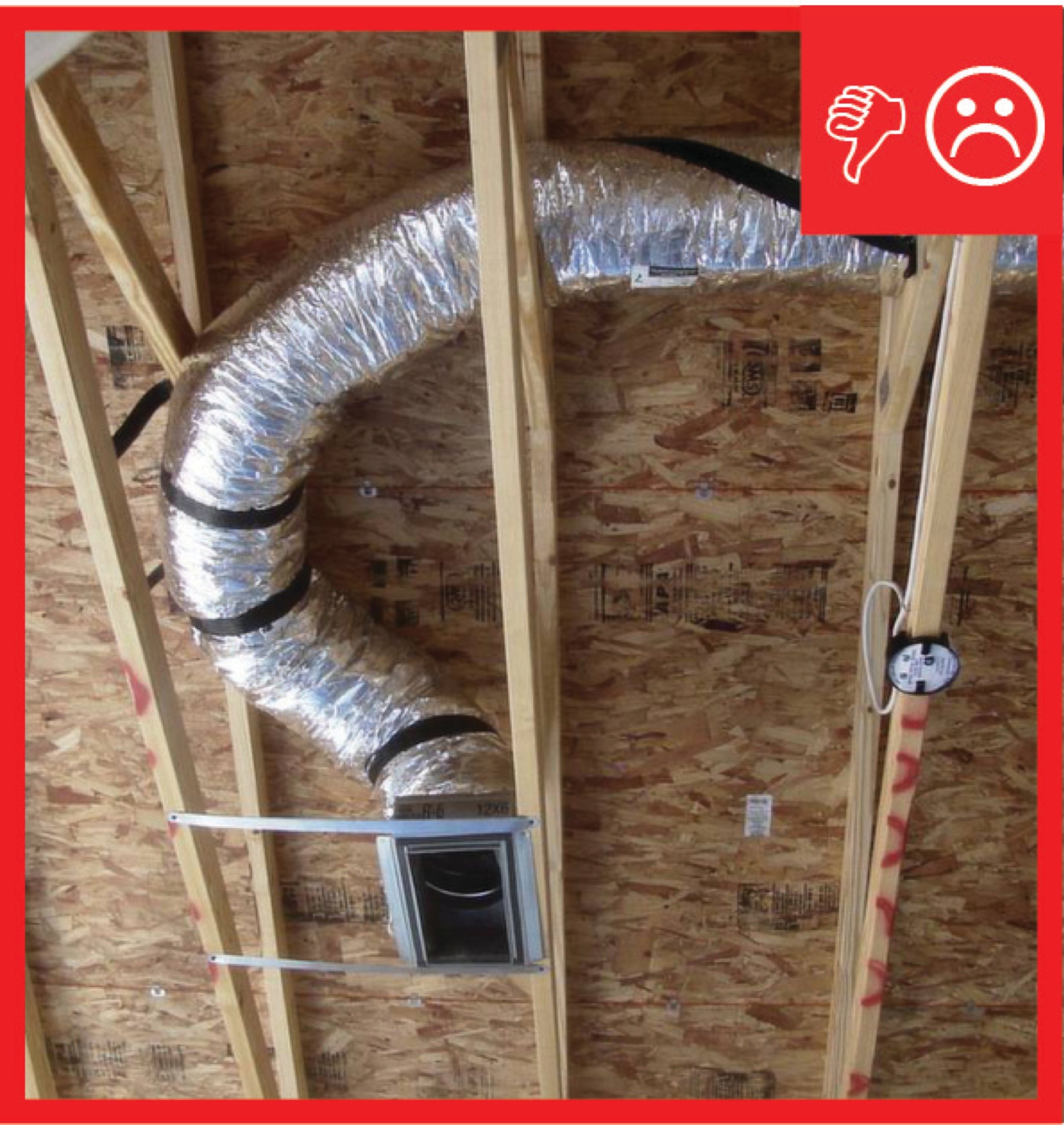
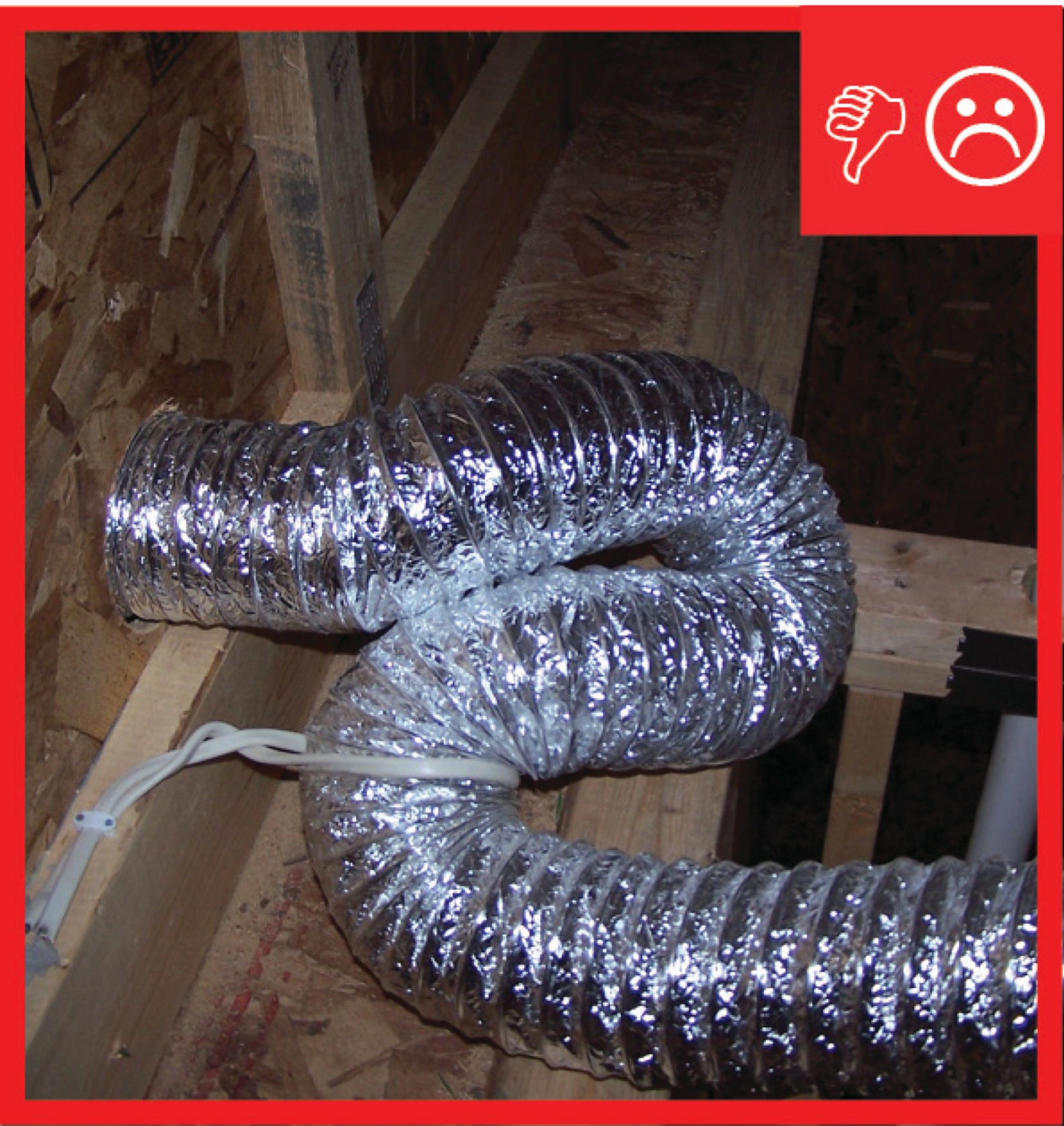
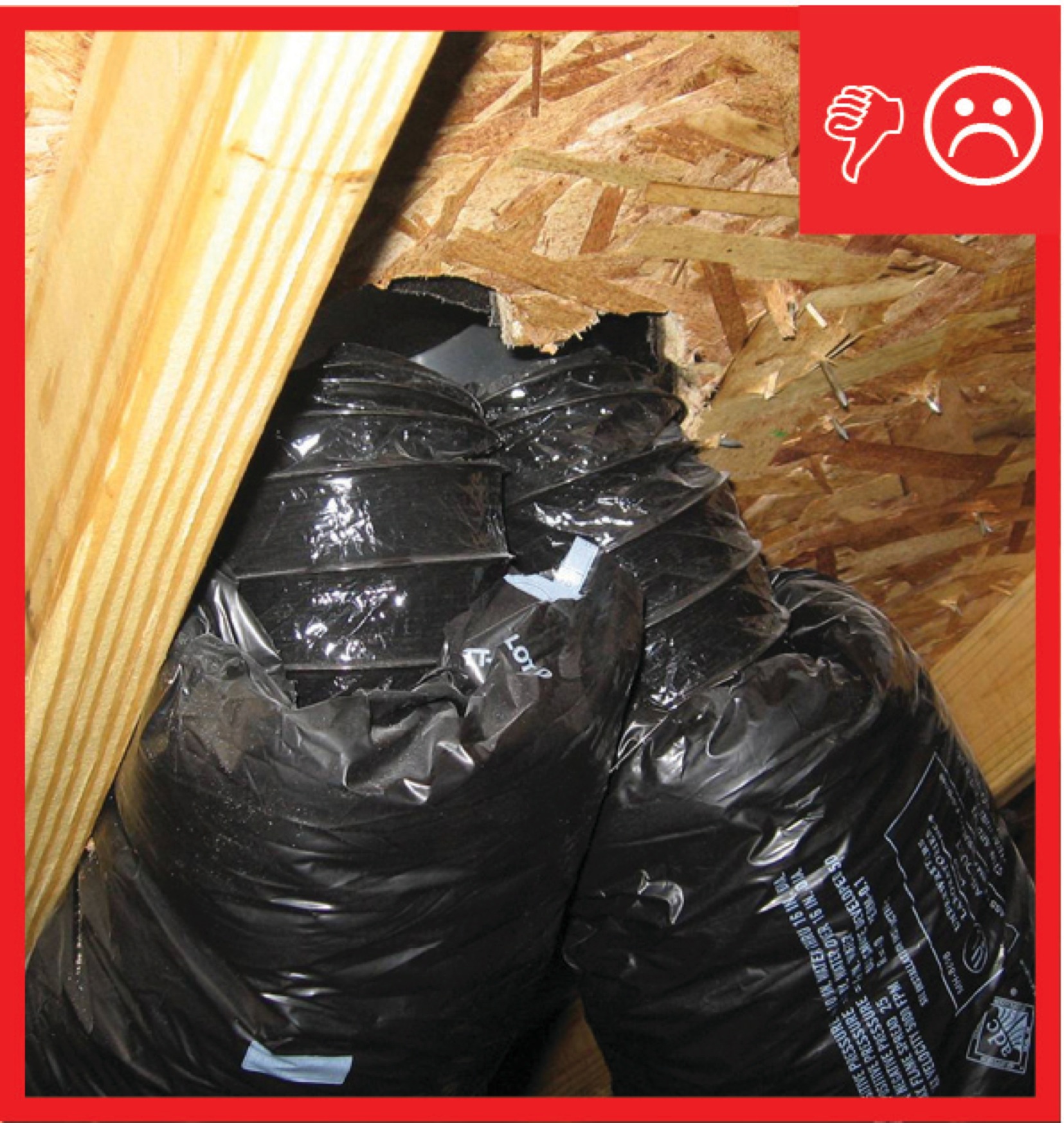
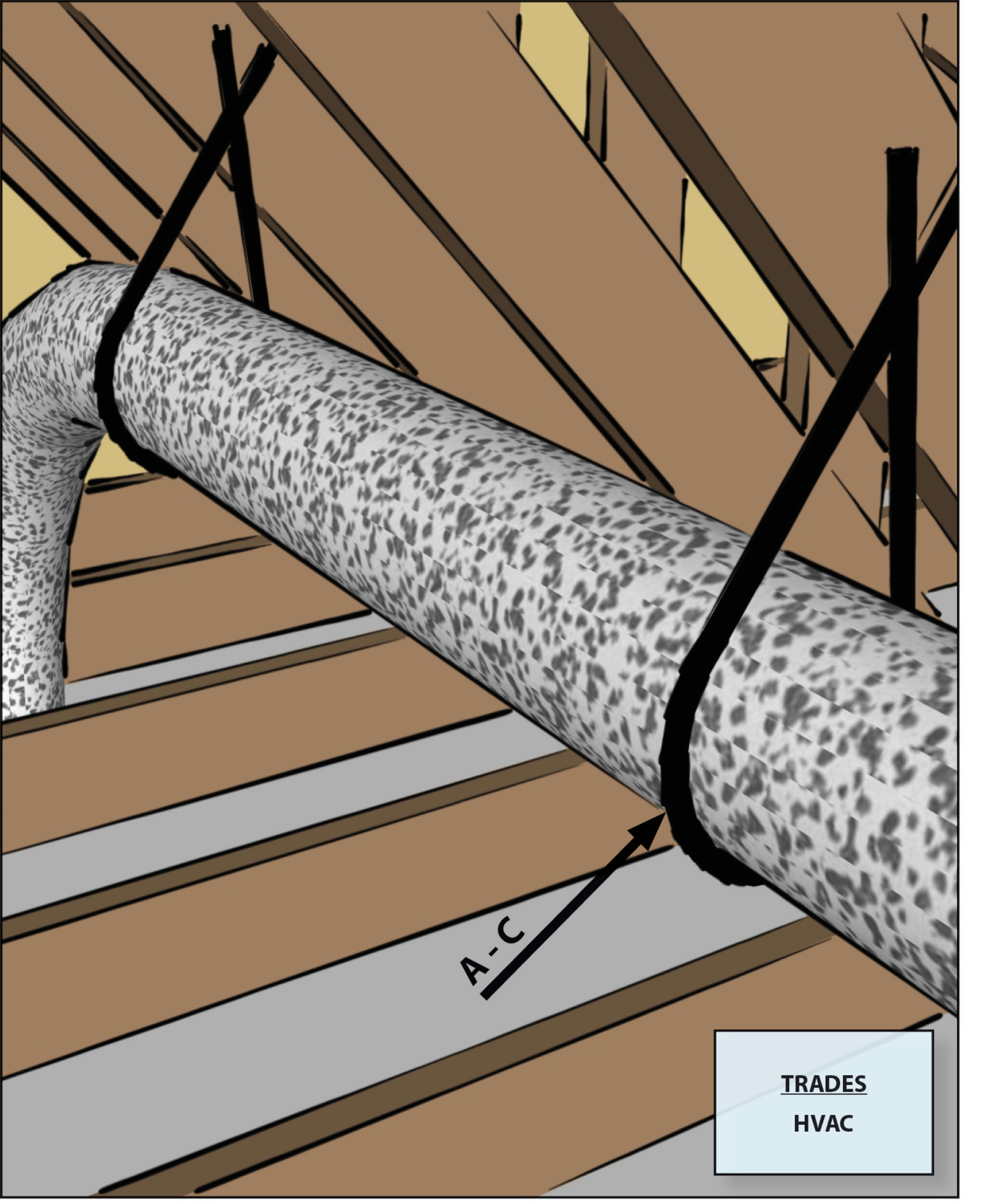
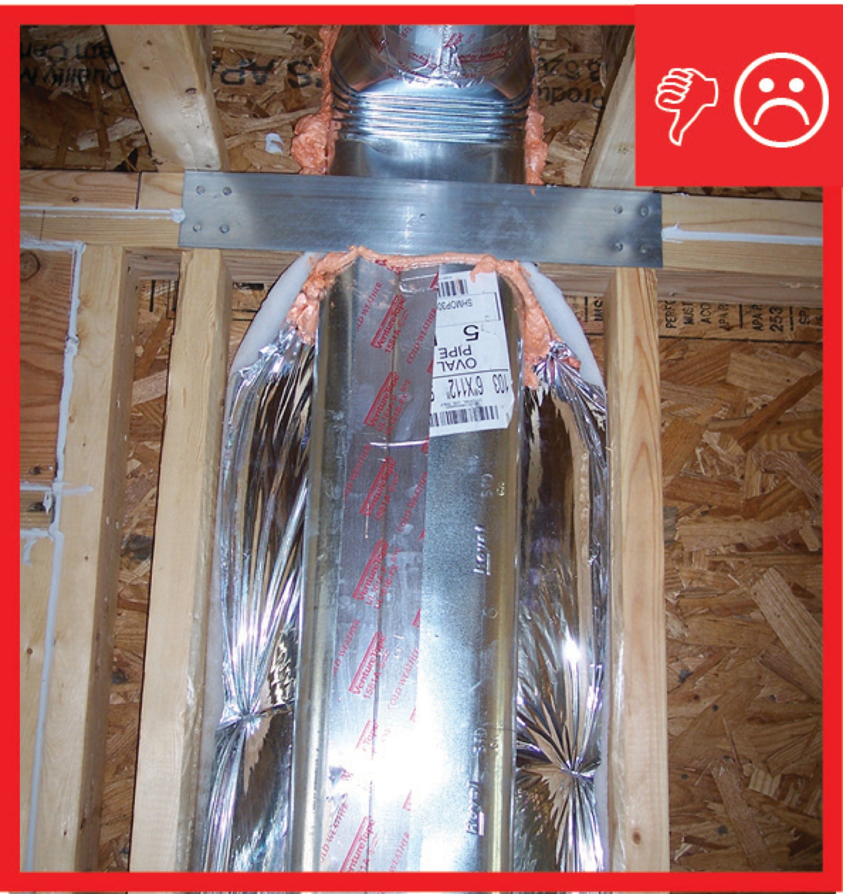
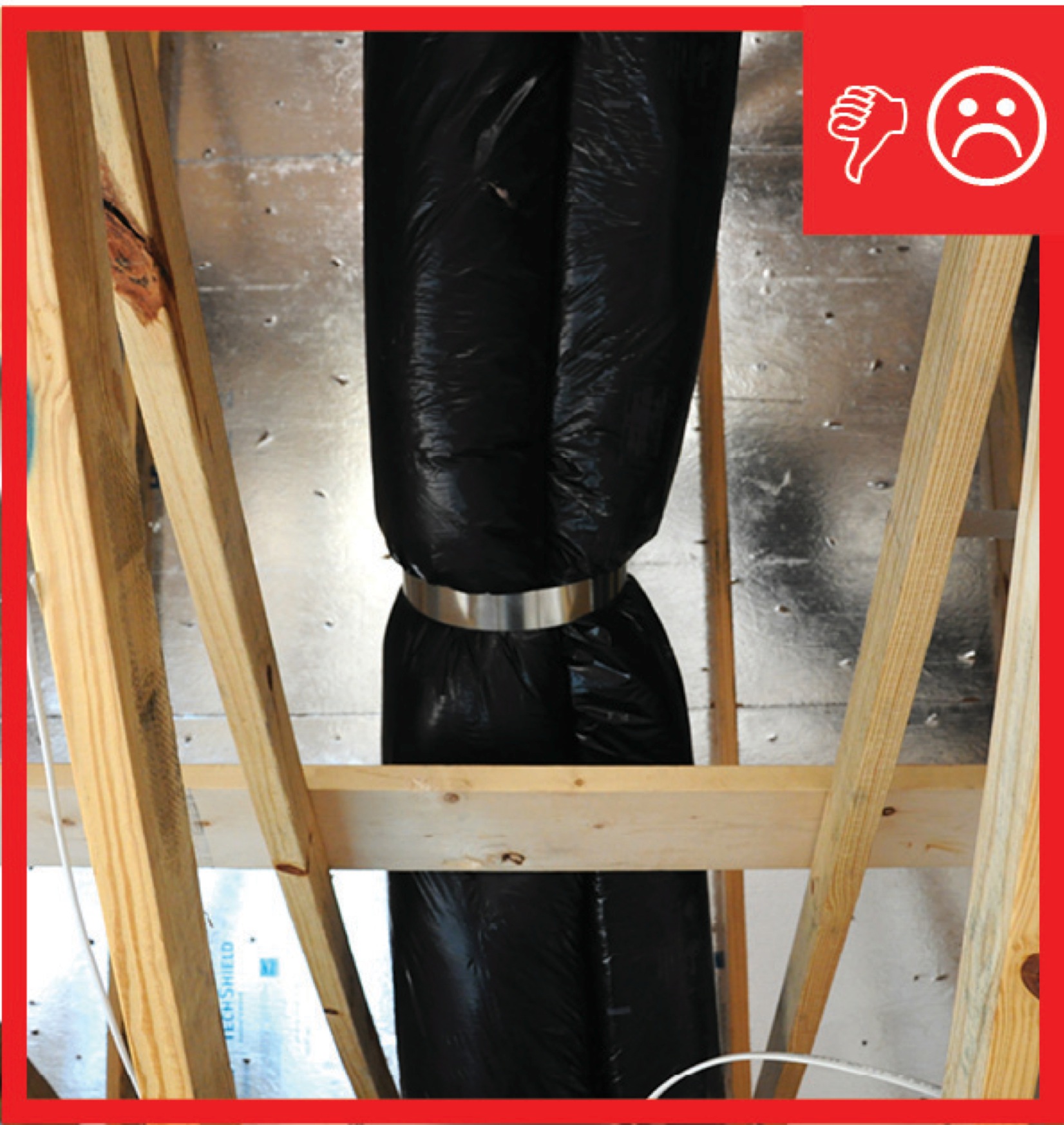
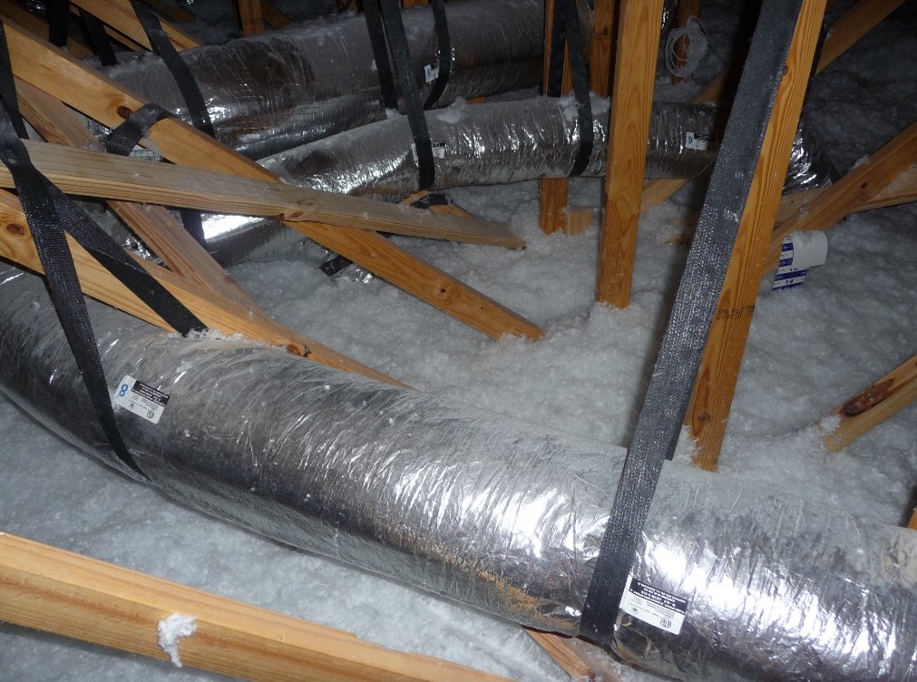
Duct lacks adequate support to carry the weight so the few straps are pinching the duct
Image
Image
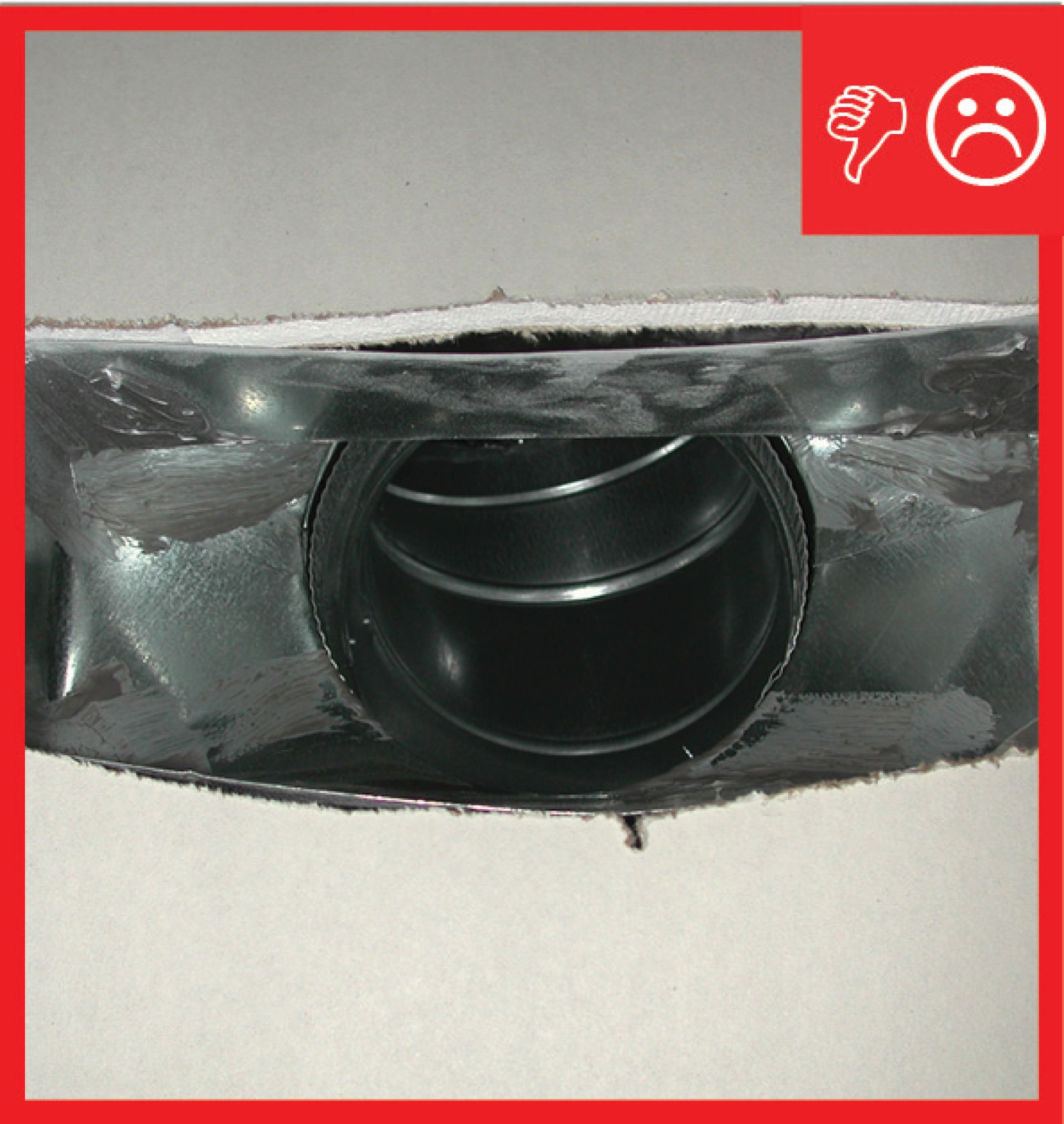
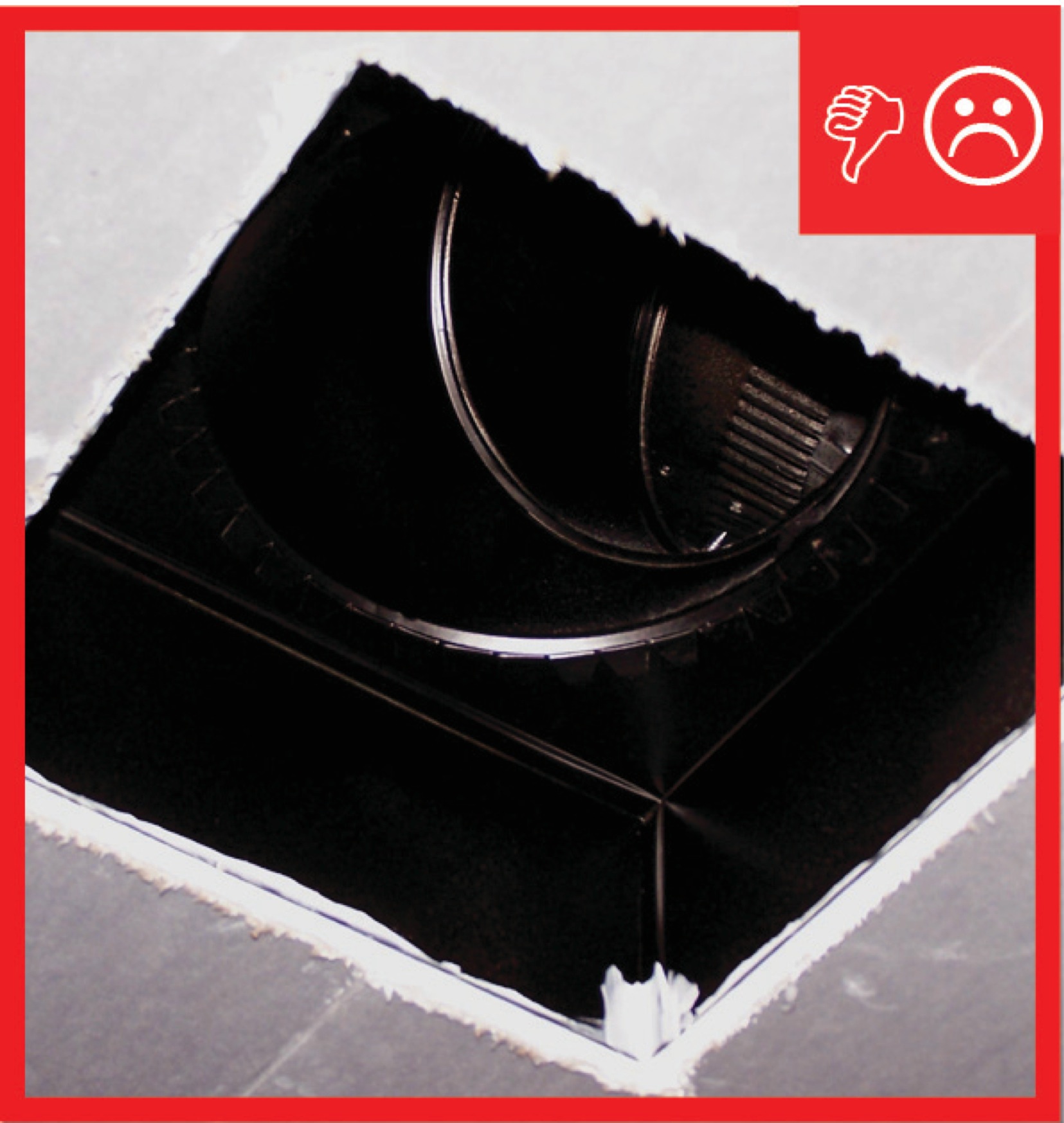
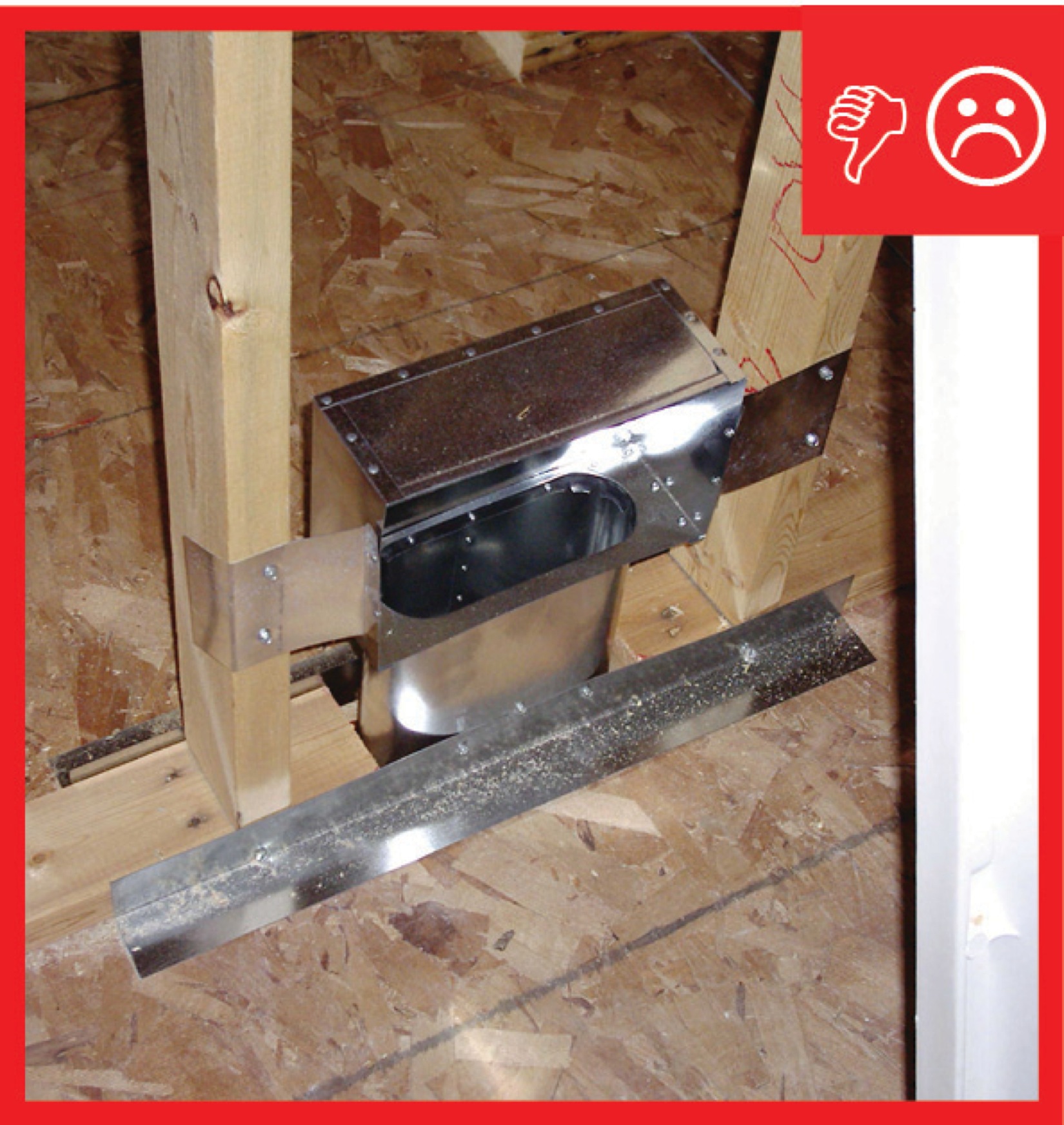
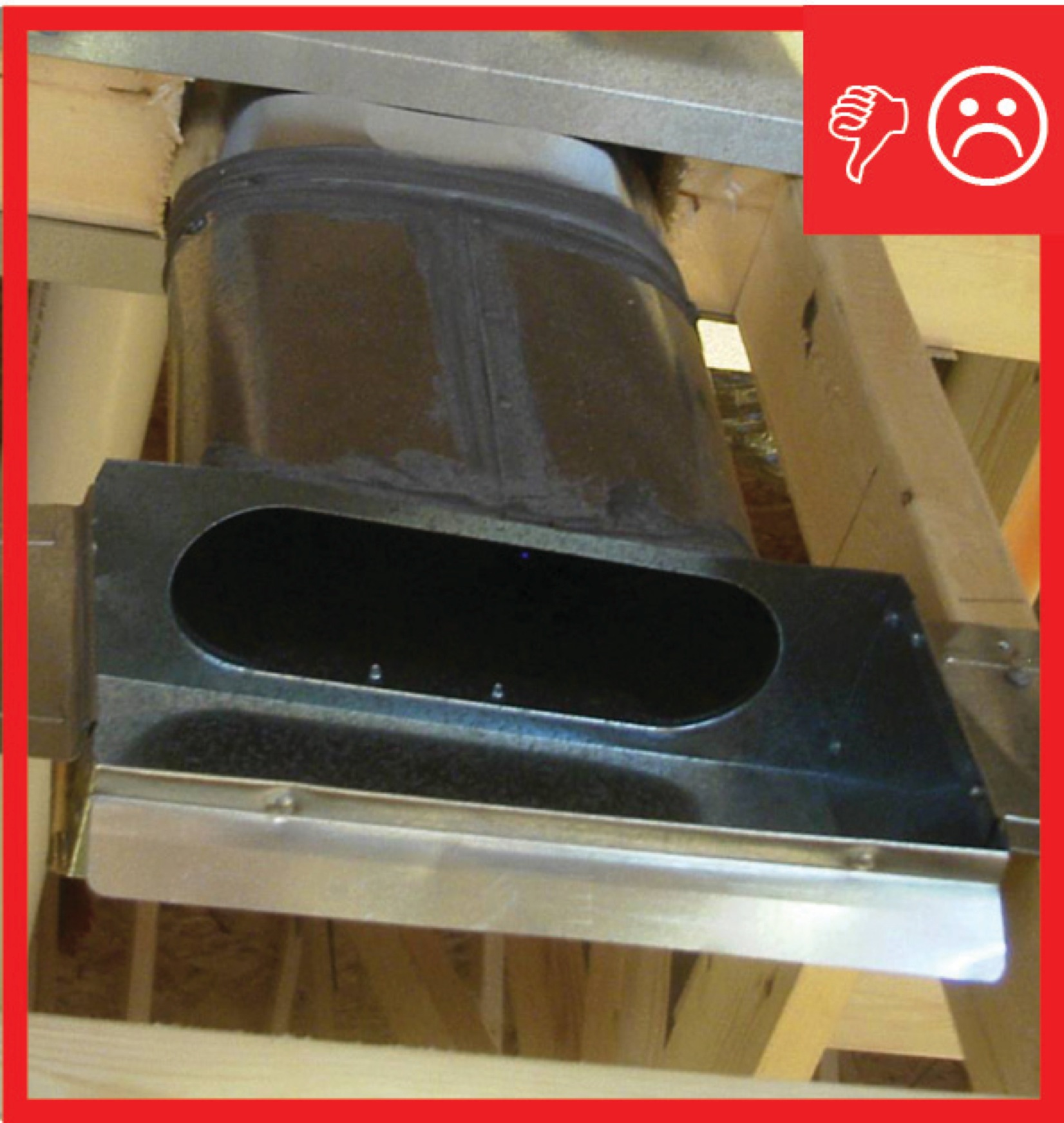
Duct to boot connection of jump duct not fastened and sealed
Image
Image
Image
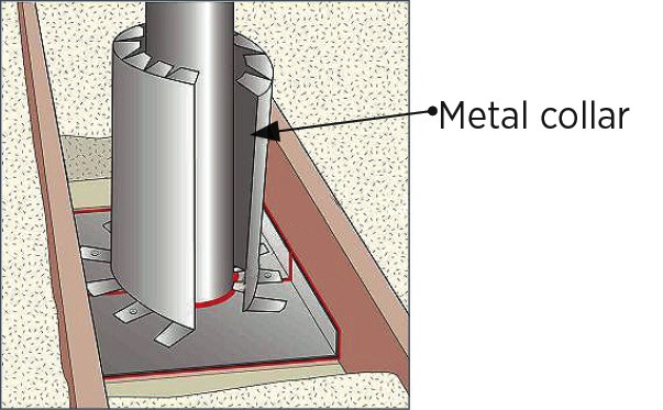
Duct/pipe penetration with metal cap flashing and wood blocking for trim attachment
Image
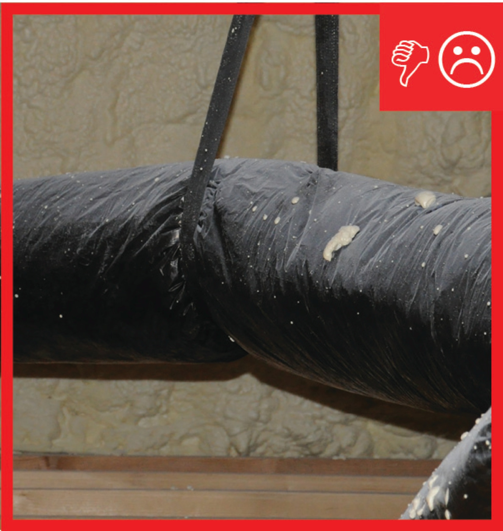
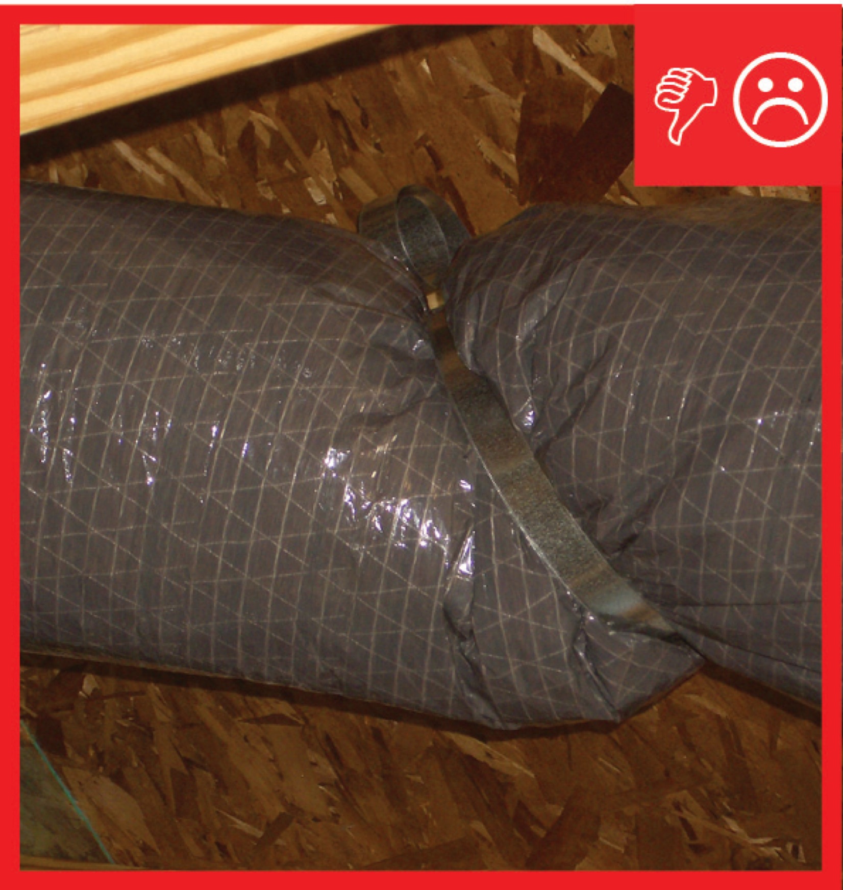
Ducts are insulated but strapping is compressing the insulation therefore reducing the R-value
Image
Image
Image
Image
Image
Image
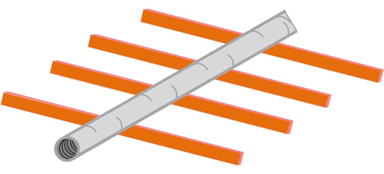
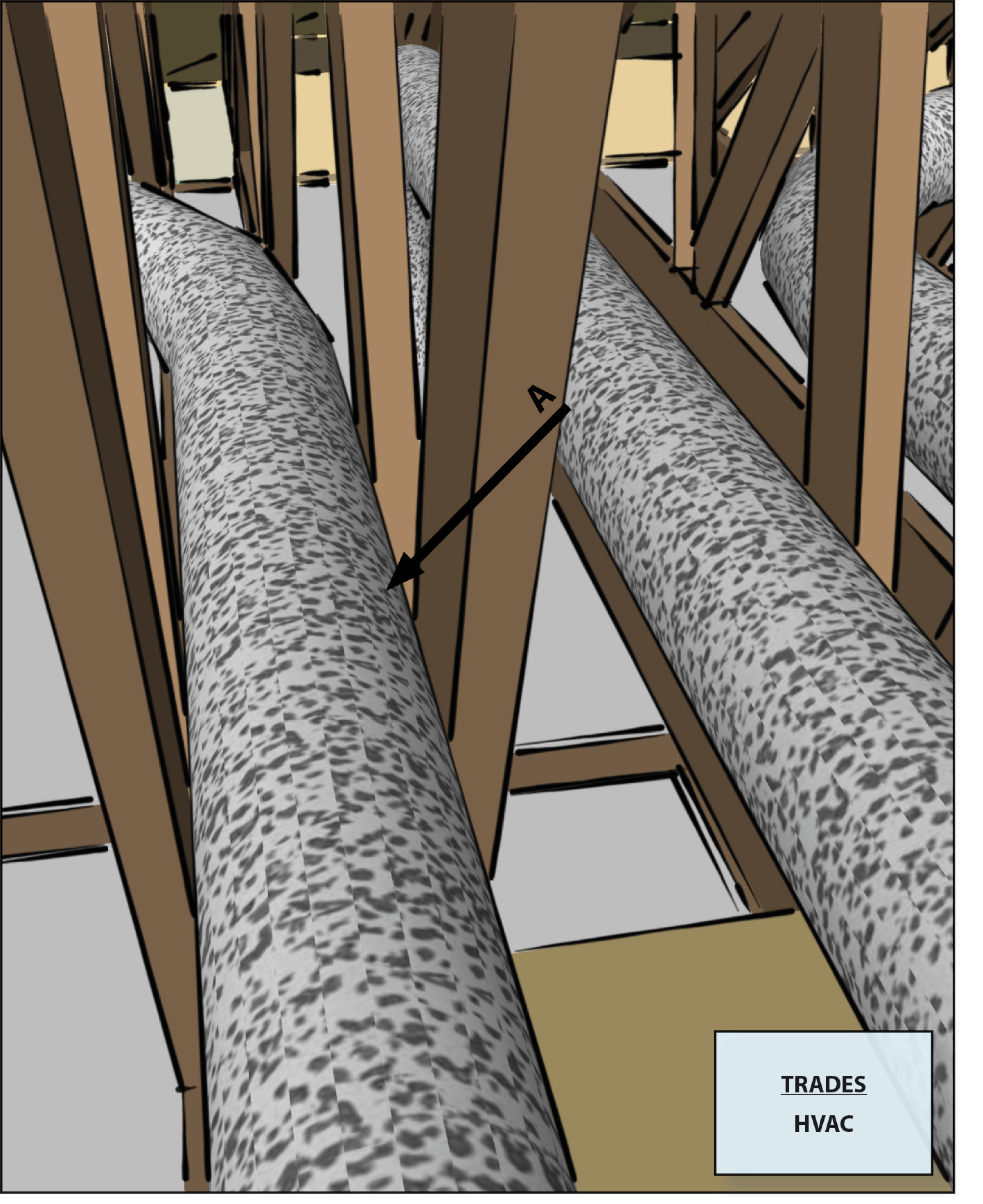
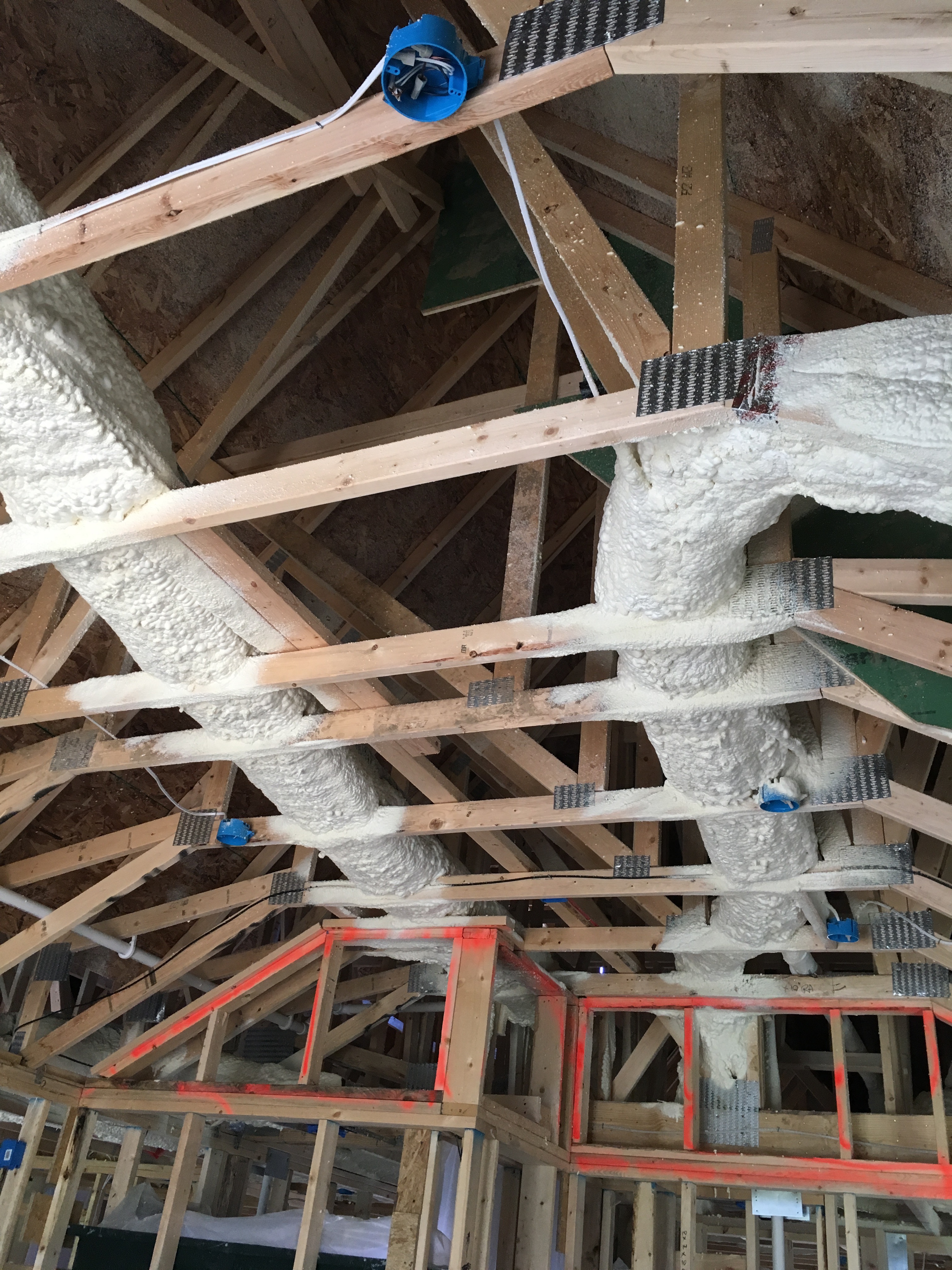
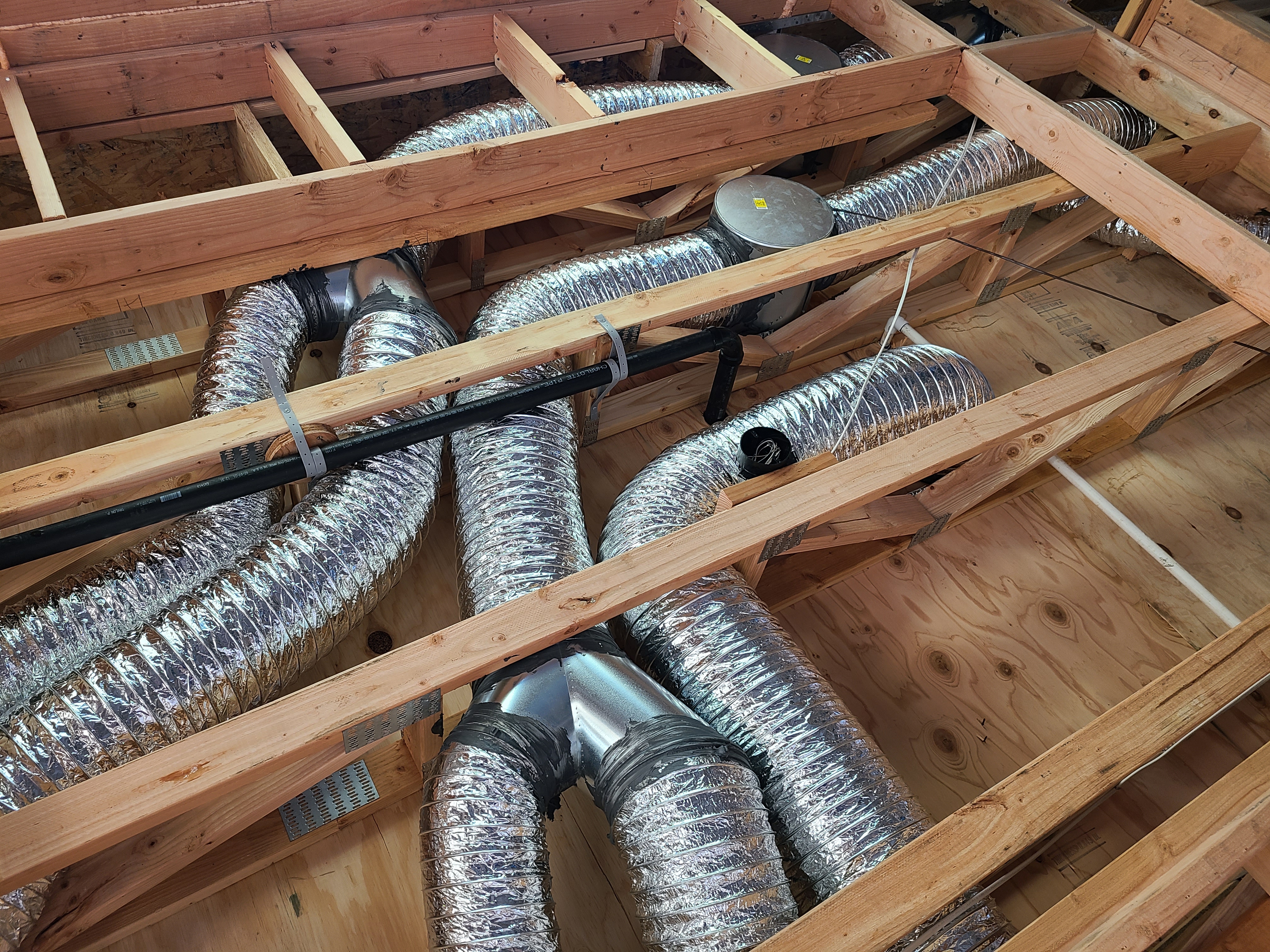
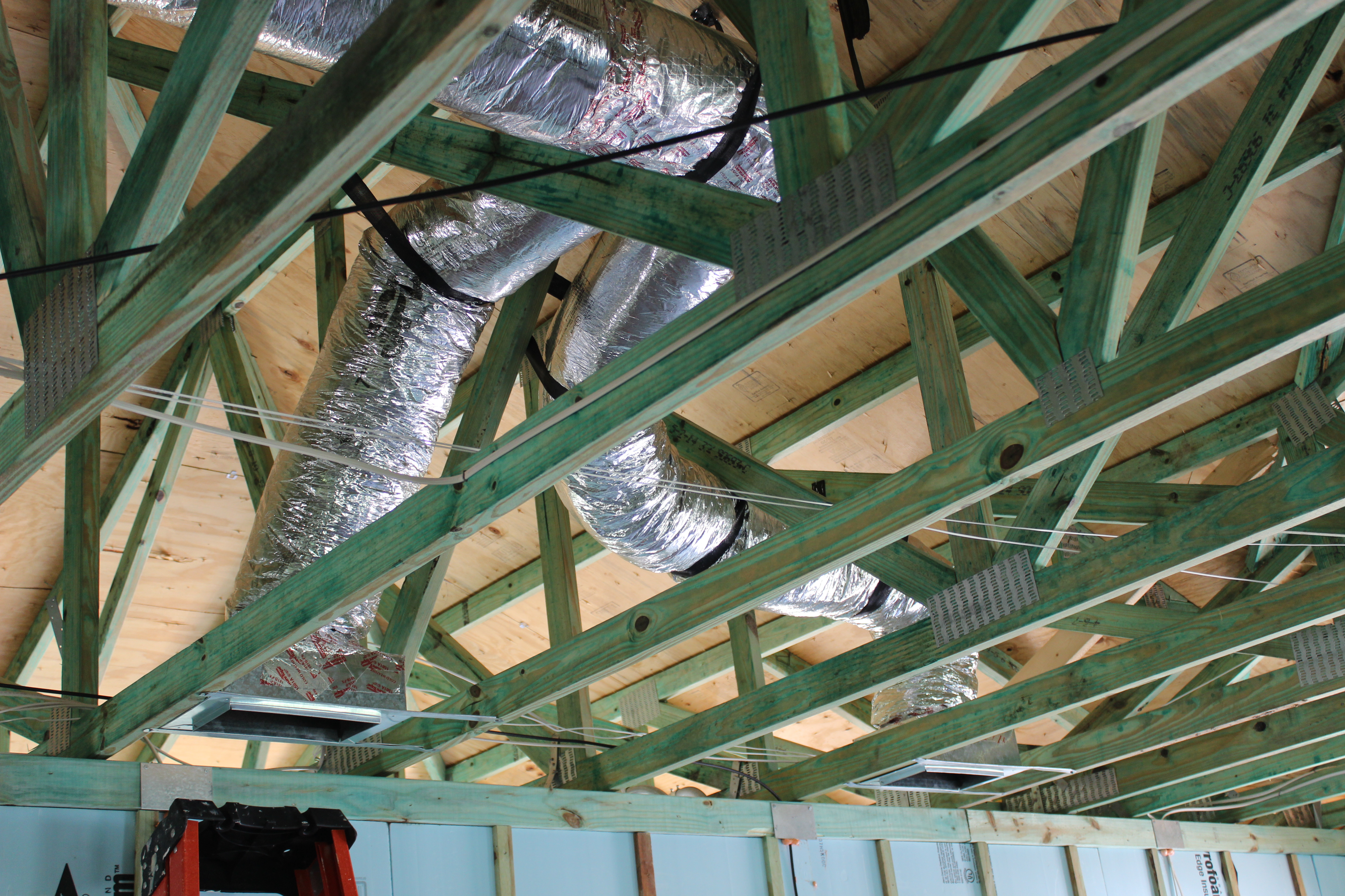
Ducts running parallel to trusses have limited width due to truss spacing
Image
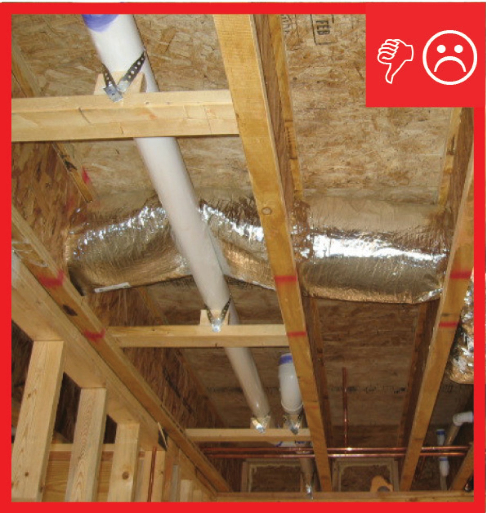
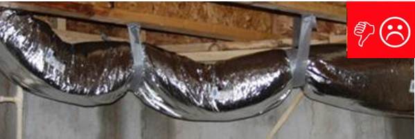
Ducts sagging because supports not installed at regular intervals
Image
Image
Image
Image
Image
Image
Image
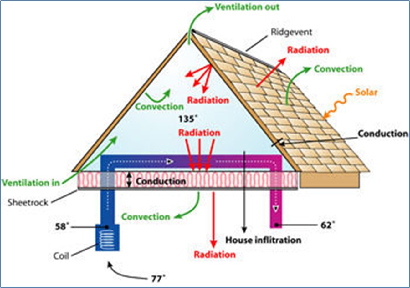
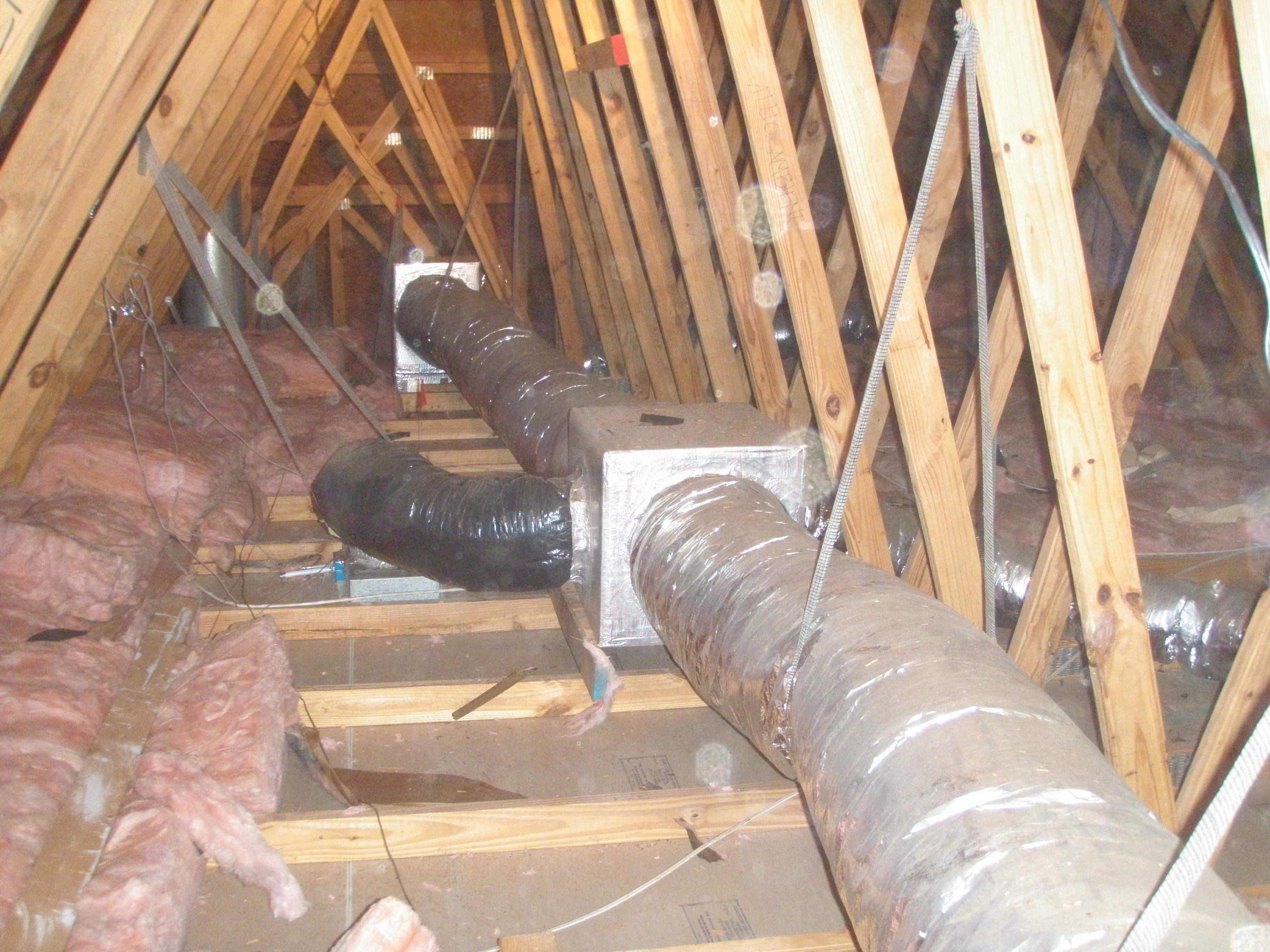
Ductwork located in a vented attic is subject to high attic temperatures and significant heat gain through the walls of the ducts
Image
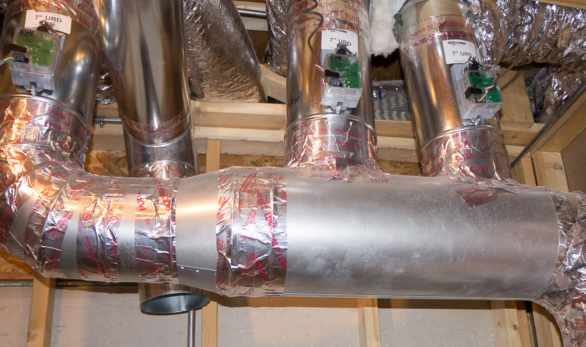
Electronically controlled dampers allow this central air system to provide zoned heating and cooling to specific parts of the home.
Image
Image

Image
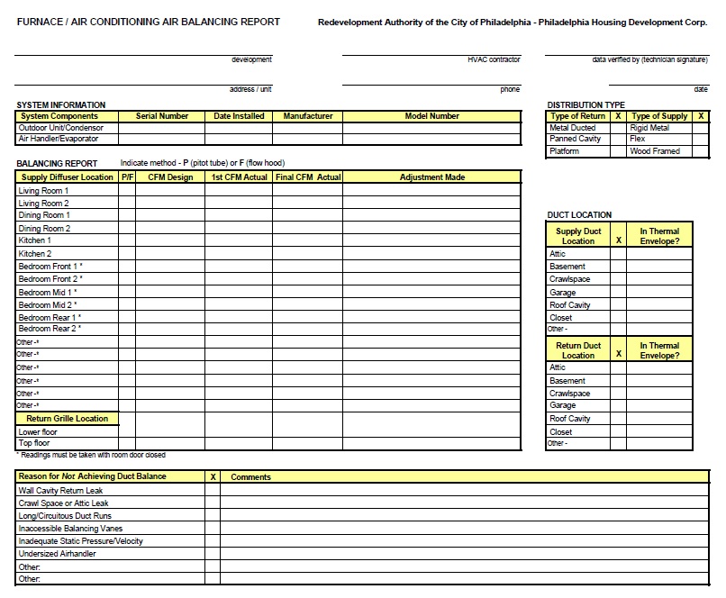
Example of an HVAC installer’s balancing report form
Image
Image
Image
Image
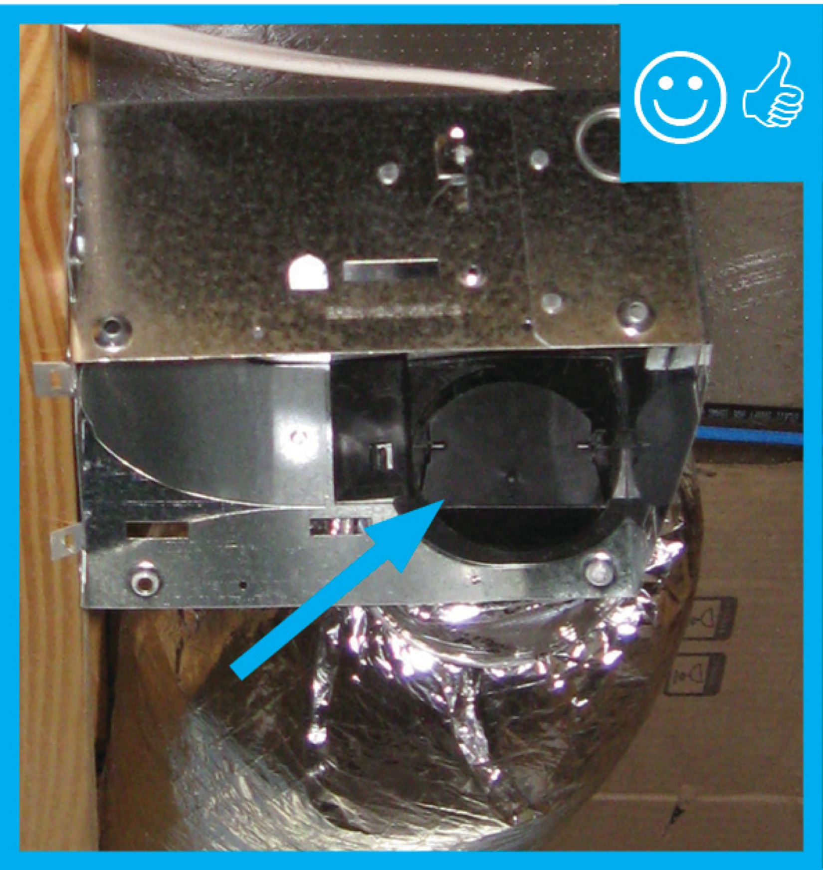
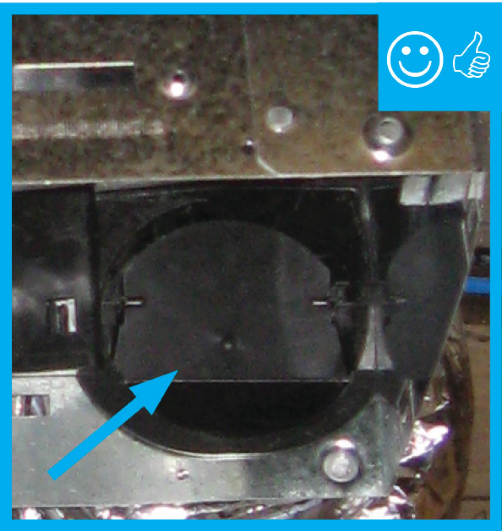
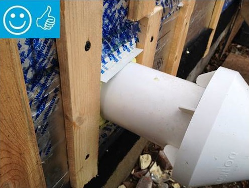
Fan housing was oriented in the correct direction to allow proper exhaust duct installation
Image
Image
Image
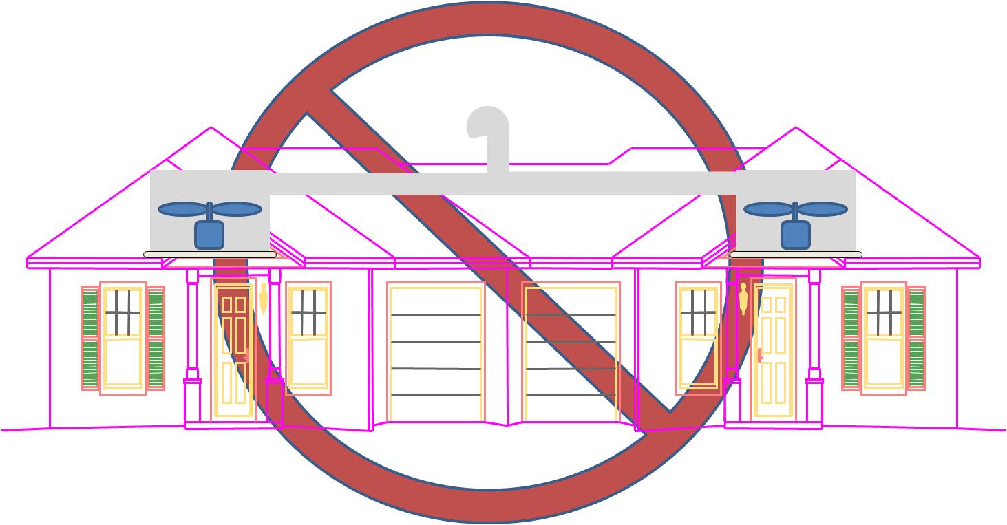
Fans from seperate dwellings exhausted together without back-draft dampers and not sealed
Image
Image
Image
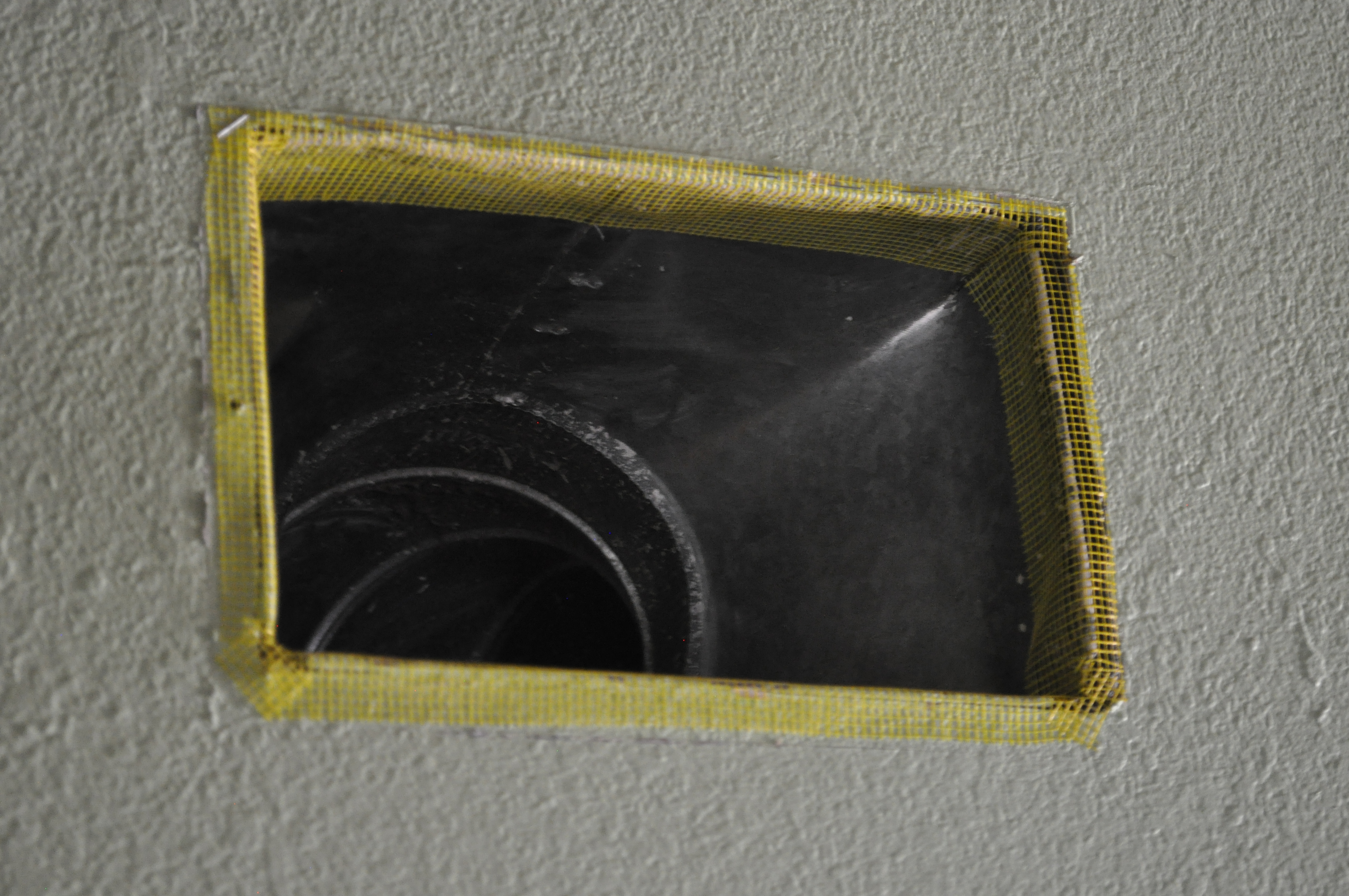
Fiberglass mesh tape is installed around a duct boot in preparation for air sealing with mastic
Image
Finished raised ceiling duct chase
Image
Image
Image
Image
Image
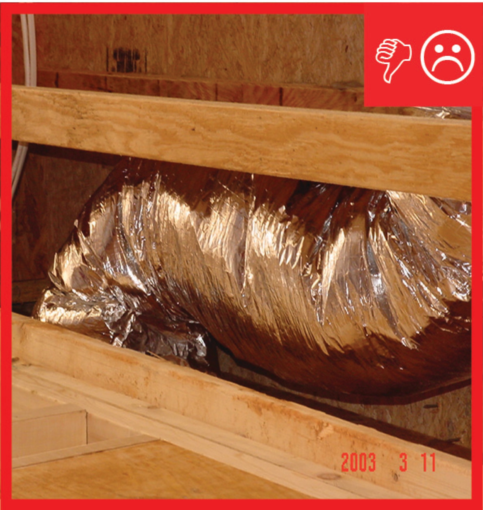
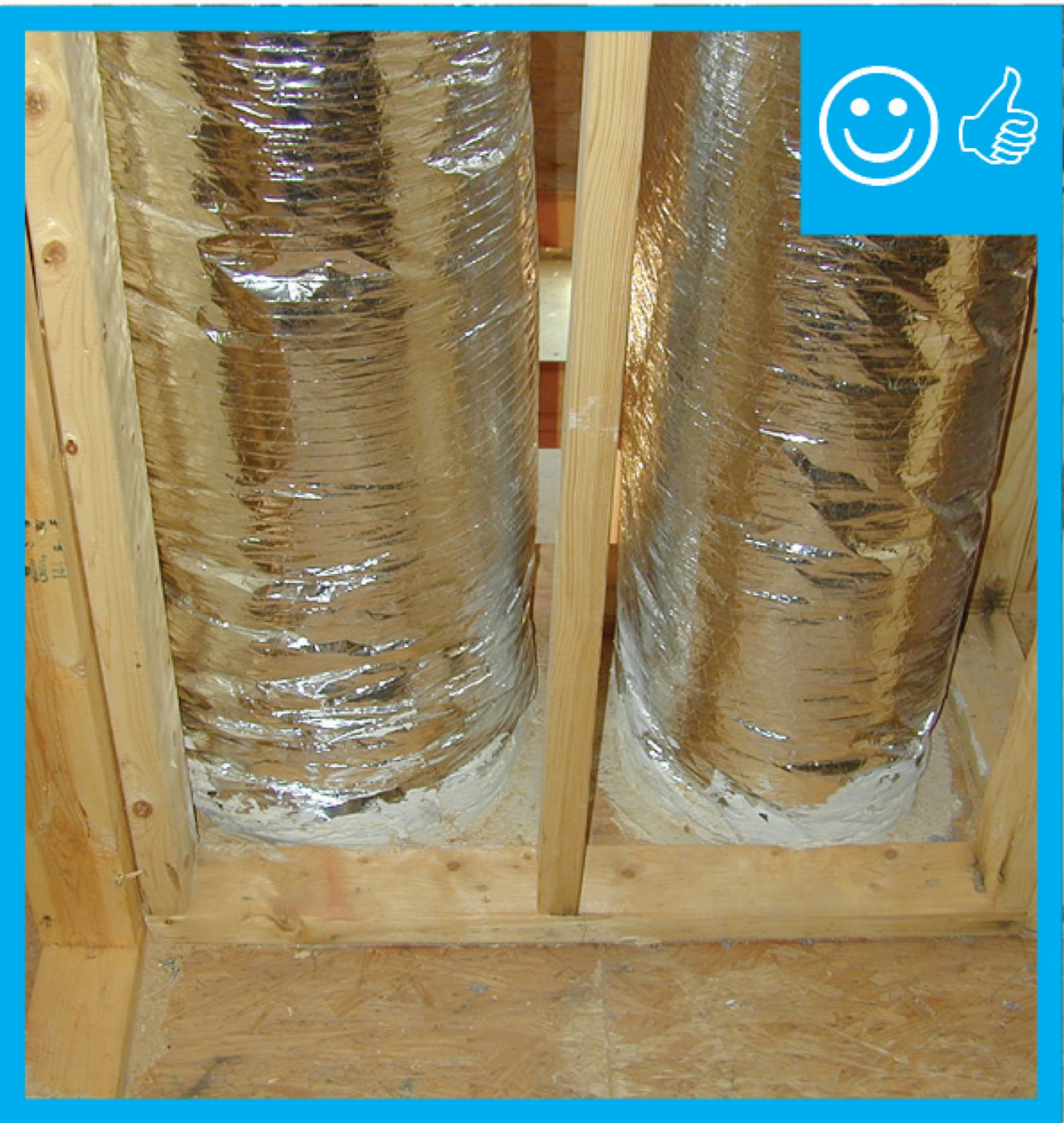
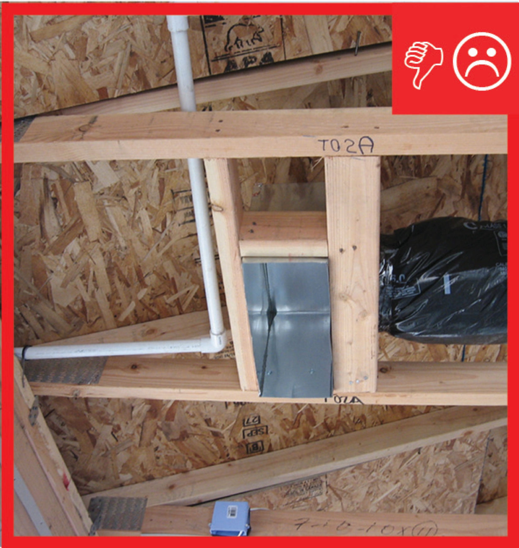
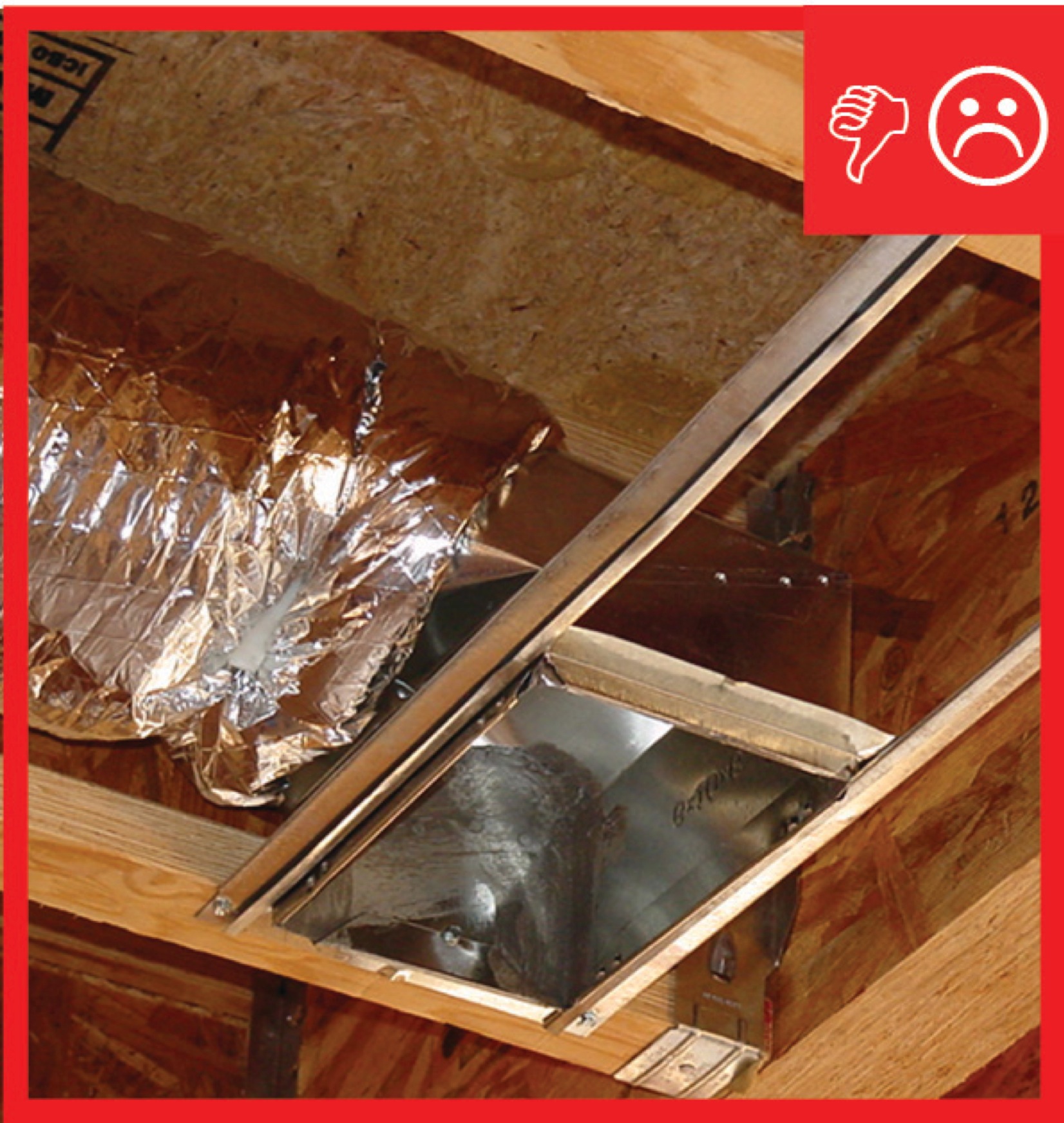
Flexible ducts in unconditioned space not installed in cavities smaller than outer duct diameter; in conditioned space not installed in cavities smaller than inner duct diameter
Image
Flexible ducts supported at intervals as recommended by mfr. but at a distance ≤ 5 ft
Image
Image
Image
Image
Image
Image

Fresh air intakes and exhaust vents are ducted to each unit in this multifamily building
Image
Image

Hand tools for cutting fiber board sheets include a knife, straight edge, and color-coded edge-cutting tools
Image
Image
Image
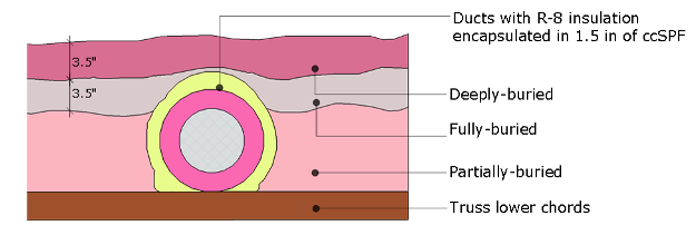
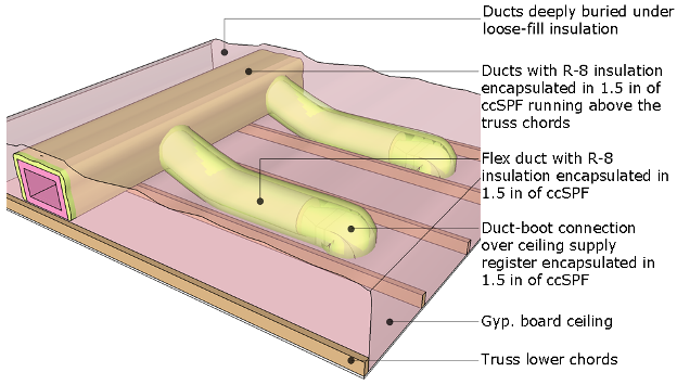
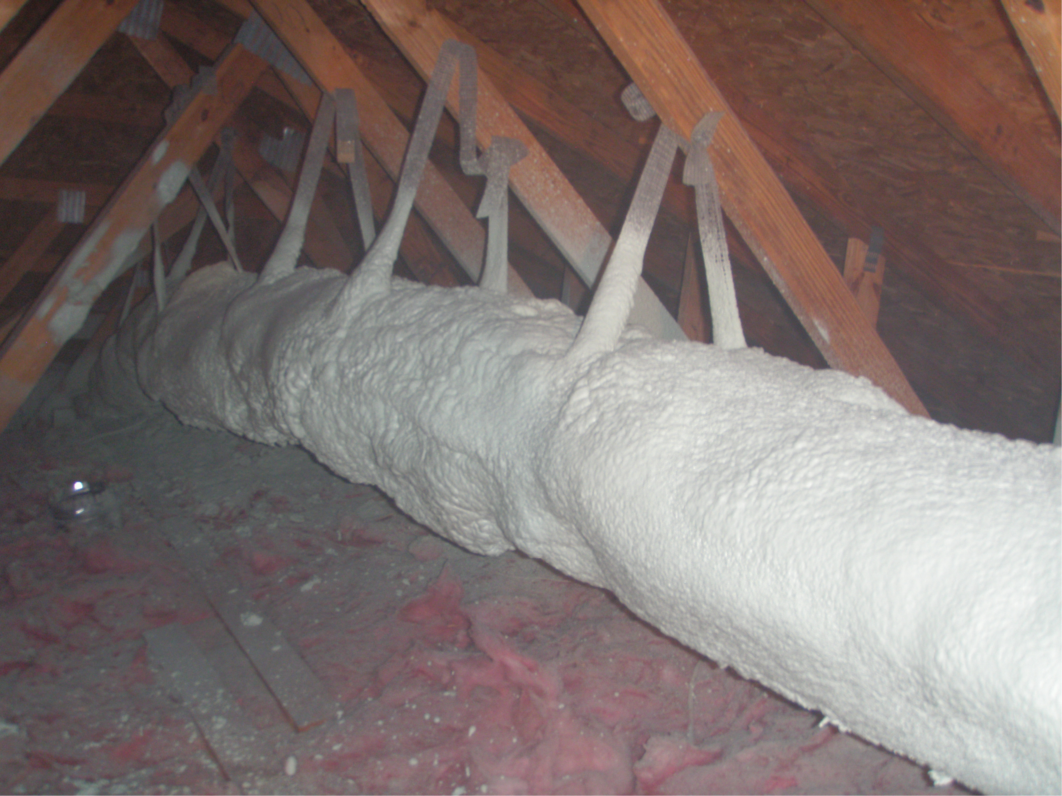
HVAC ducts can be encapsulated in 3 inches of closed-cell spray foam, then buried in R-49 of blown fiberglass insulation after the ceiling drywall is installed in the vented attic.
Image
HVAC ducts, cavities used as ducts, and combustion inlets and outlets may pass perpendicularly through exterior walls but shall not be run within exterior walls unless at least R-6 continuous insulation is provided on exterior side of the cavity
Image
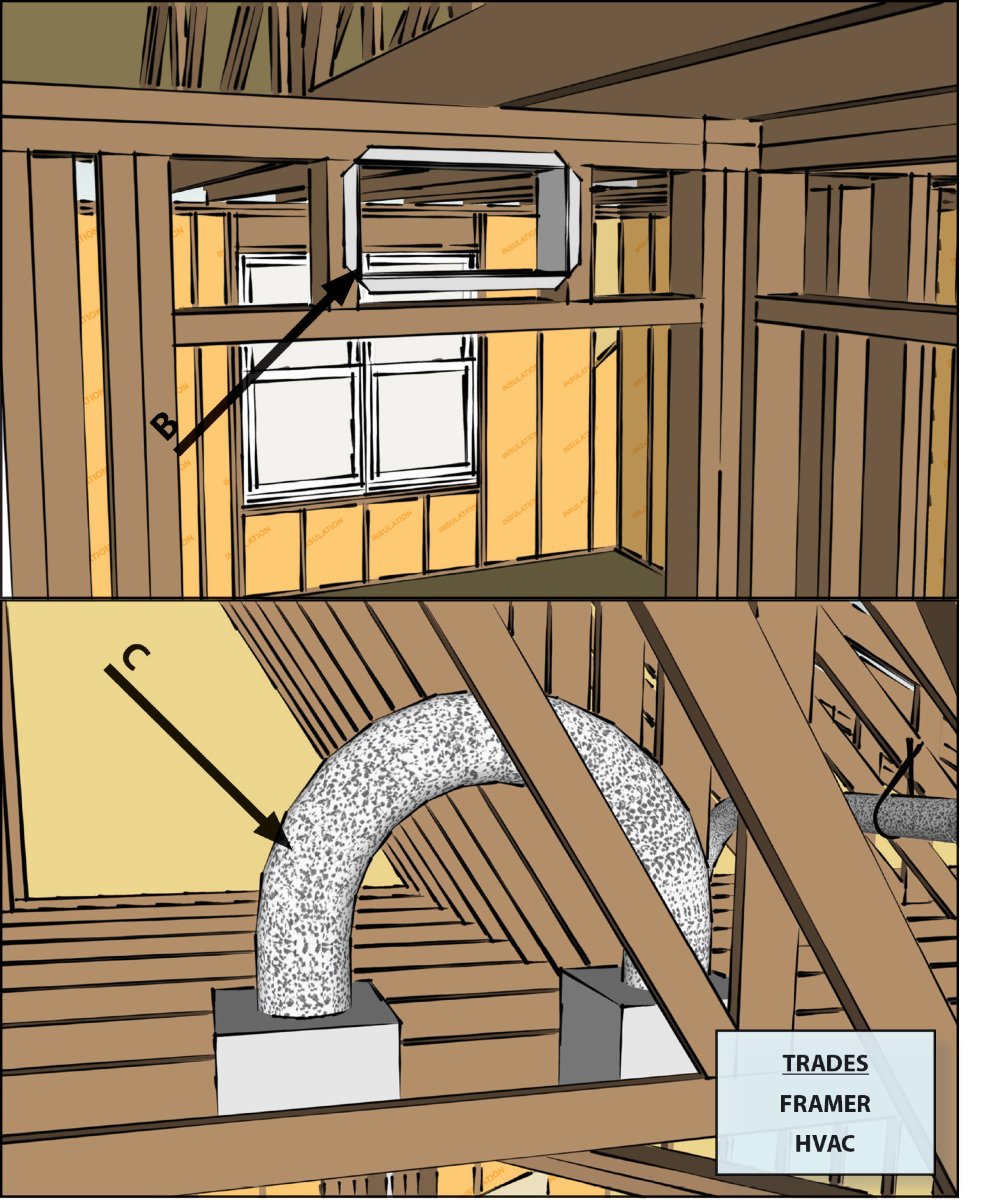
If a dropped soffit is used to house a duct, the soffit space must equal the duct diameter plus the insulation thickness
Image

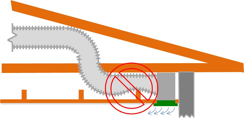
If airflow must be limited to a supply register, use balancing dampers at the trunk line rather than looping duct to control airflow
Image
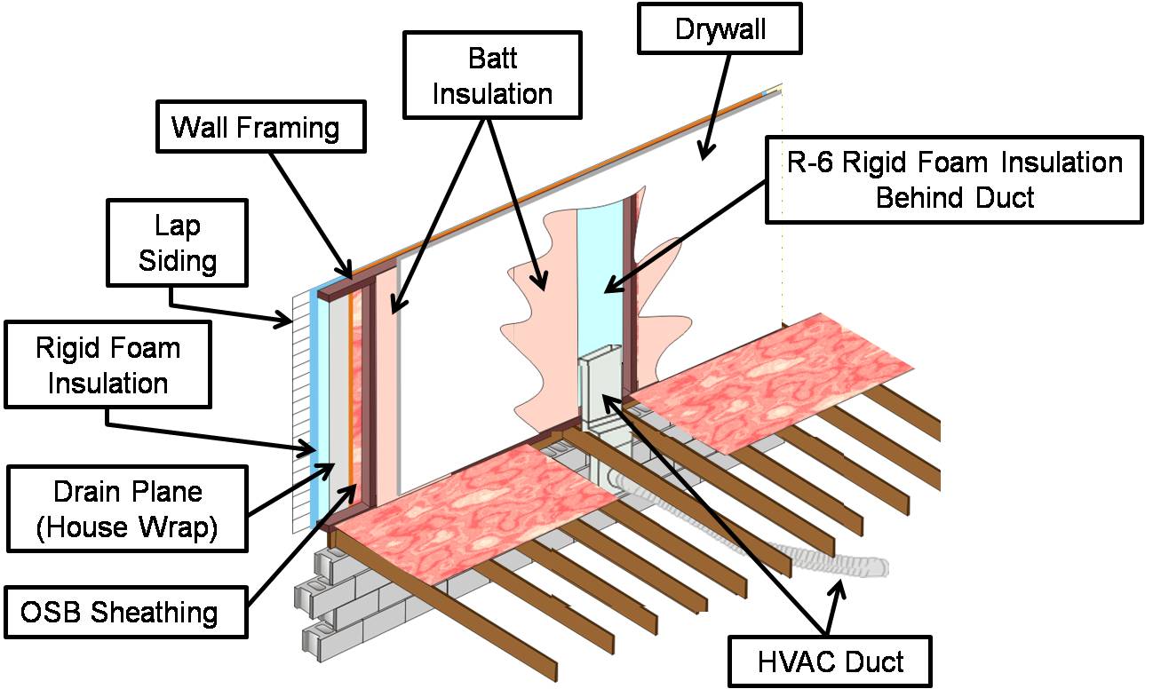
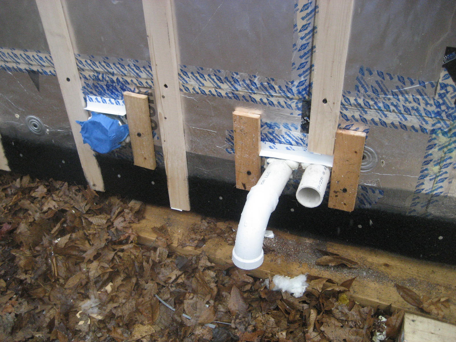
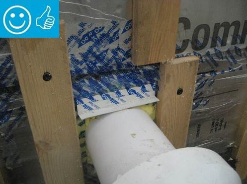
If HVAC duct must be installed in an exterior wall, separate it from the exterior with at least R-6 of continuous rigid insulation
Image
Image
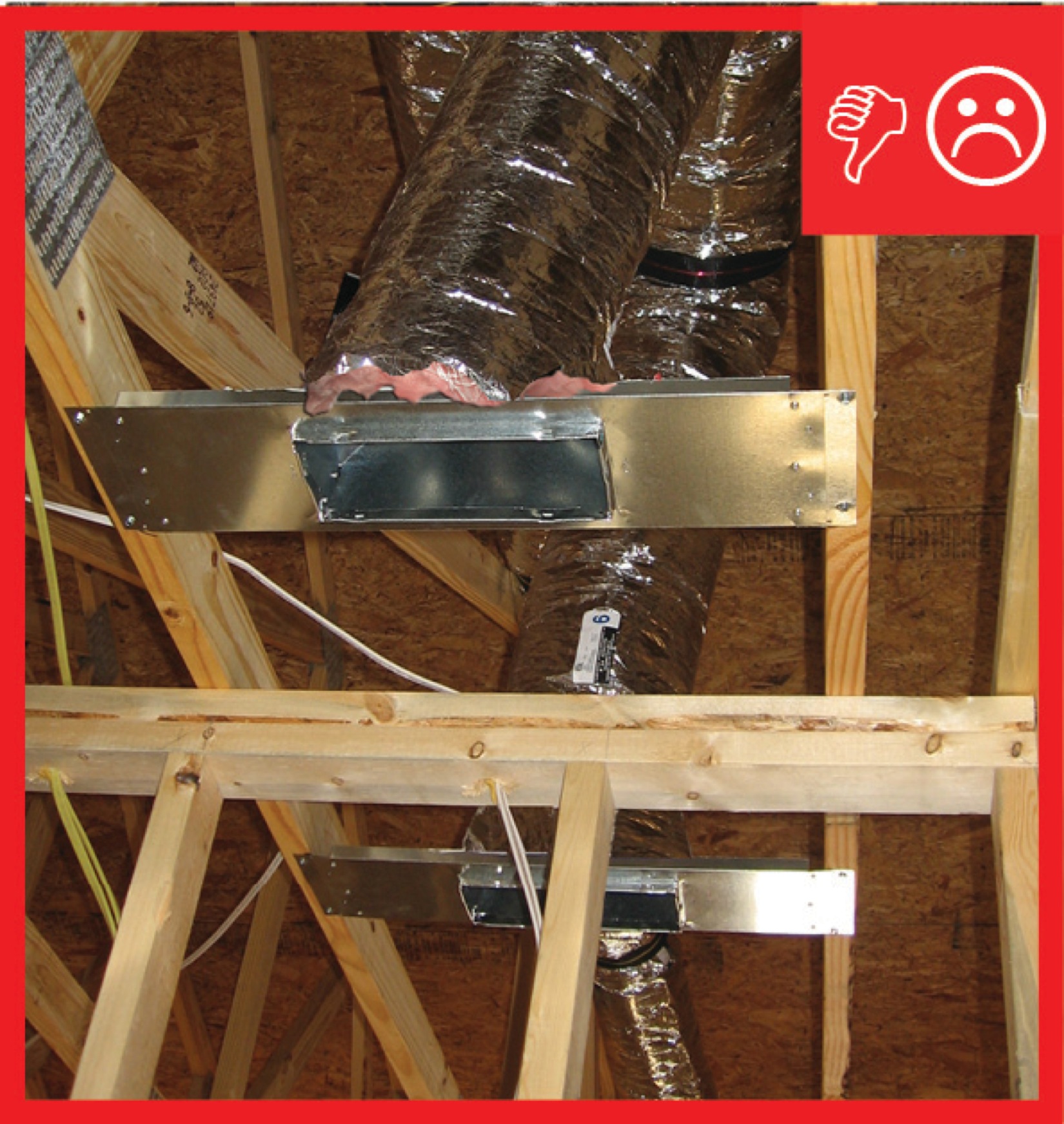
Inadequate amount of insulation installed with compression, misalignment, and voids
Image

Install bottom layer of rigid insulation
Image
Install duct supports in line with ceiling trusses
Image
Image
Image
Install supply registers in floors or ceilings to avoid routing ducts through exterior walls
Image
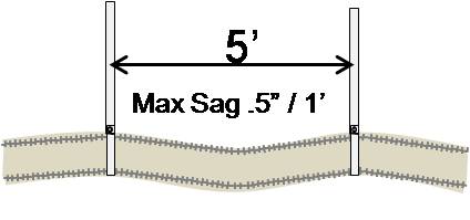
Install supports every 5 feet so that maximum allowable sag in flexible duct is no more than one-half inch per foot
Image
Install supports every 5 feet so that maximum allowable sag in flexible duct is no more than one-half inch per foot
Image
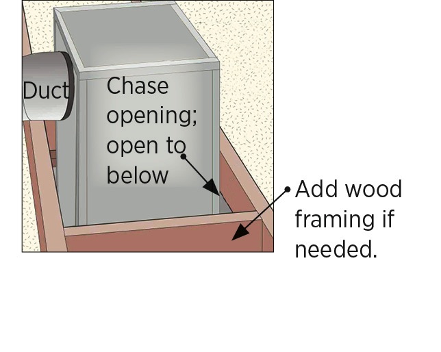
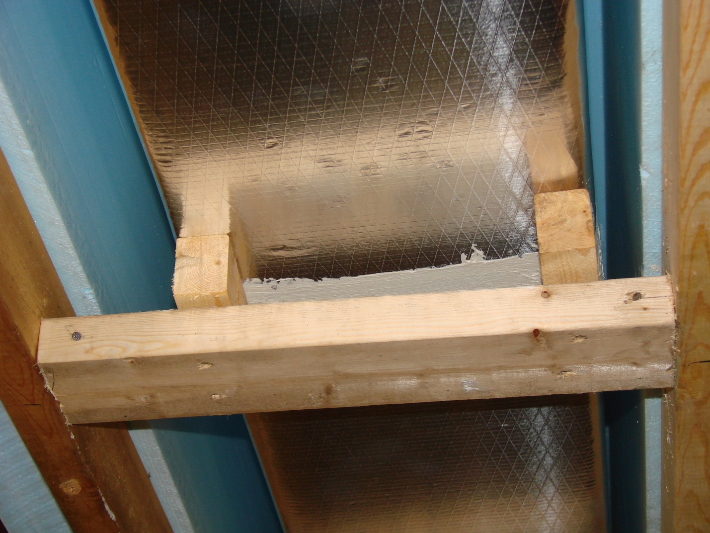
Install wood framing cross pieces in the attic rafter bays on each side of the duct chase
Image

Image
Image
Image
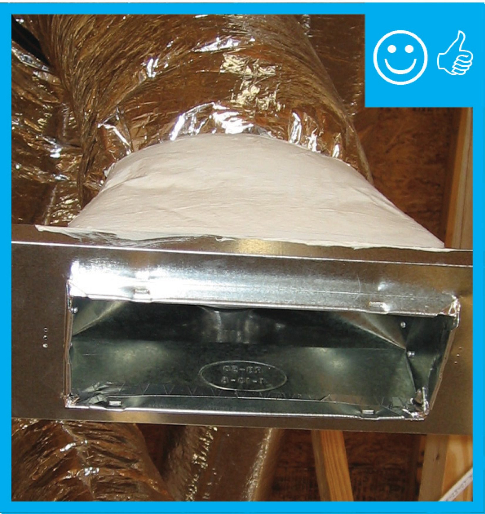
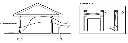
Jump ducts are installed in the ceiling to connect closed rooms with open space to provide a return air path and balance air pressure
Image

Lay out duct so that no radius of a bend or turn is less than the diameter of the airway
Image
Image
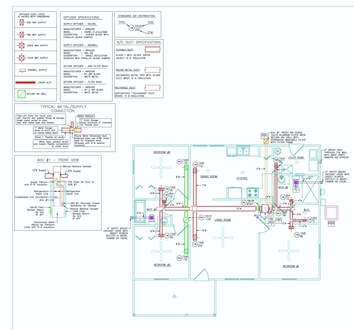
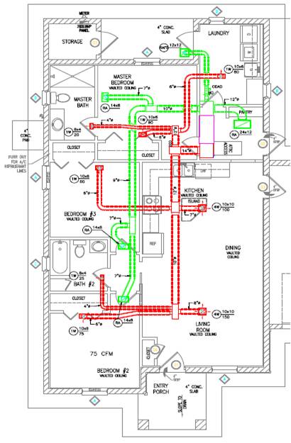
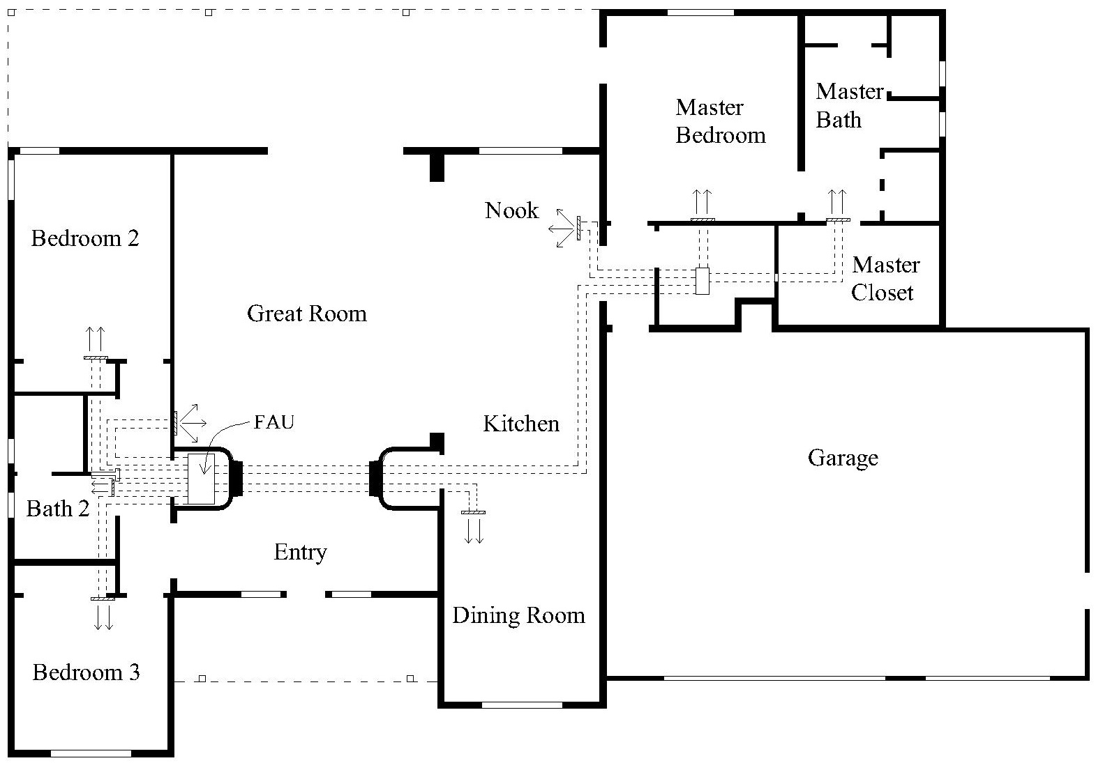
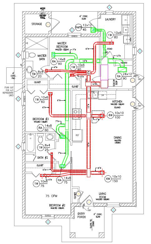
Manual D details show duct size and chase path
Image
Image
Image
Image
Image
Image
Image
Image
Image
Image
Image
Image
Image
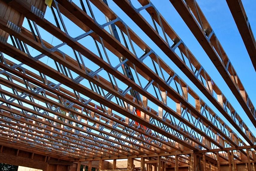
Open floor trusses used as return air plenums can draw air from any place connected to that floor
Image
Open-web floor joists provide space for ducts between the floors of a two-story home.
Image
Packing tape has been removed and damper will be able to function properly once fan is installed
Image
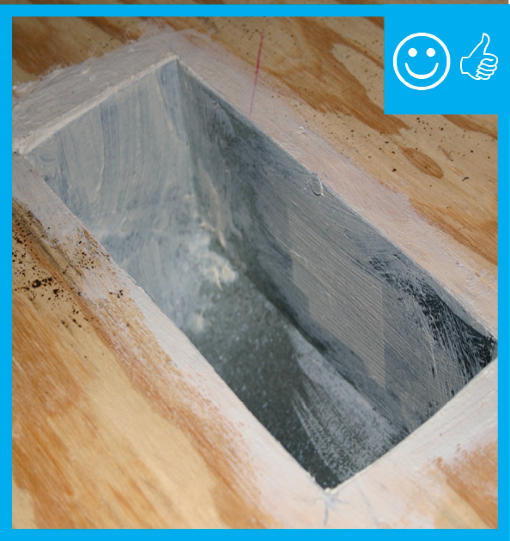
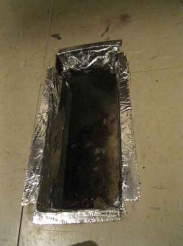
Pan stock is used to form a boot for future register installation
Image
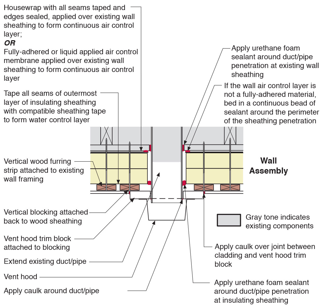
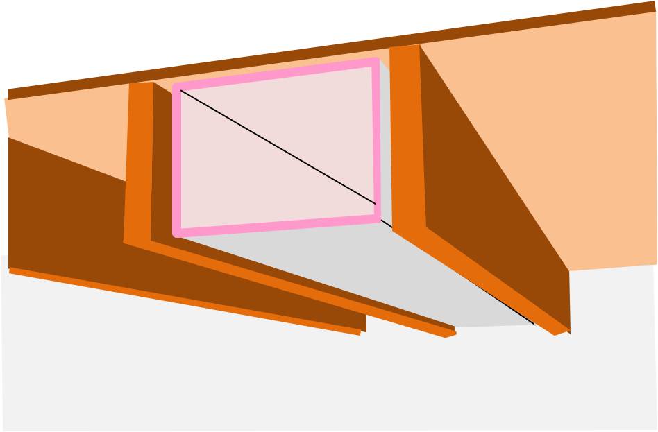
Plan view of duct or pipe penetration through exterior wall showing flashing and air sealing details
Image

Prepare chase with adhesive for bottom insulation
Image

Prescriptive Path: Supply ducts in unconditioned attic have insulation ≥ R-8. Performance Path: Supply ducts in unconditioned attic have insulation ≥ R-6
Image
Image
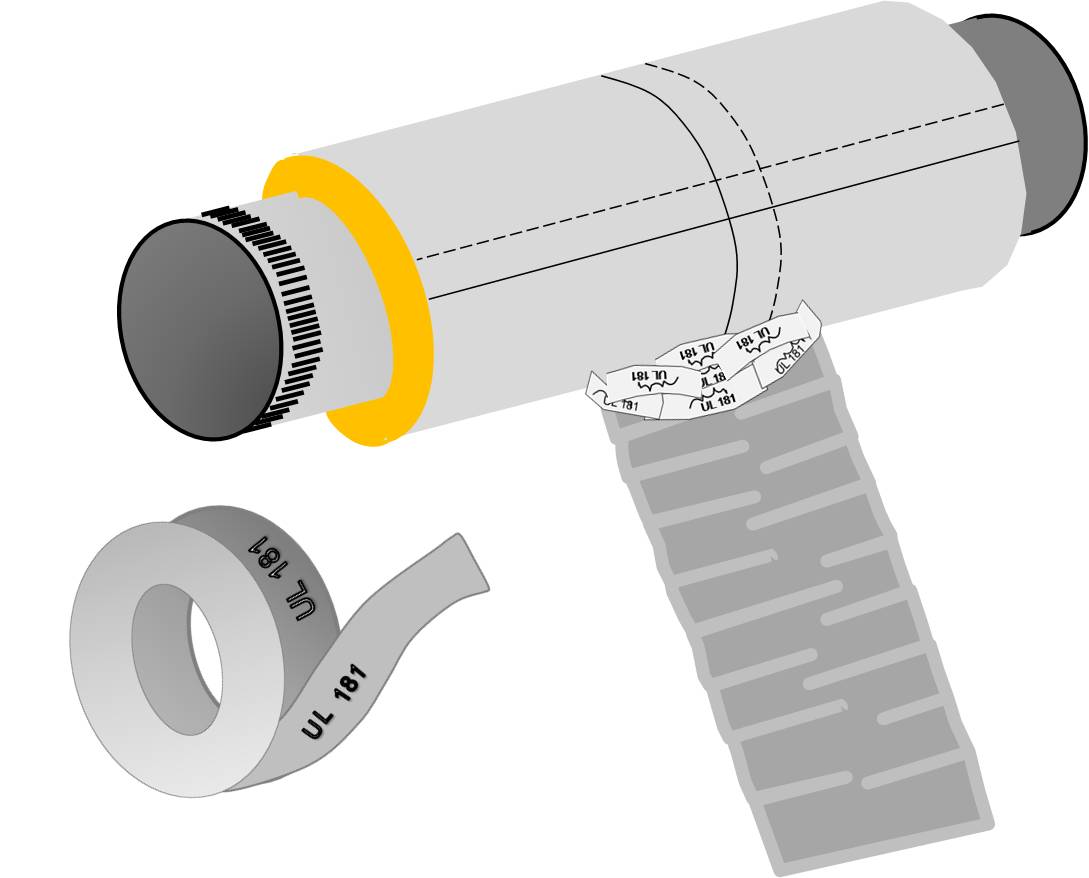
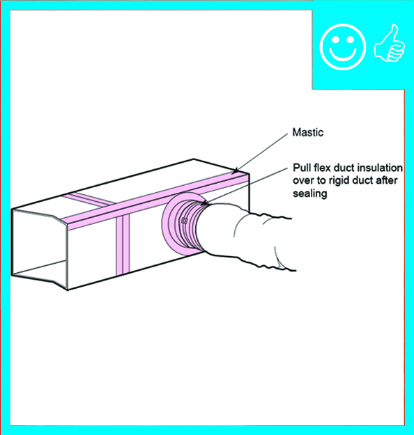
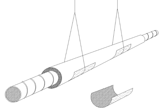
Pull the insulation and outer liner of the flex duct over the collar to come in full contact with the liner and insulation of the trunk line or fitting and tape in place
Image
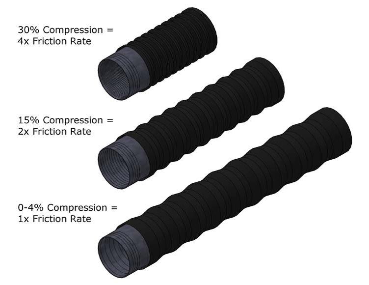
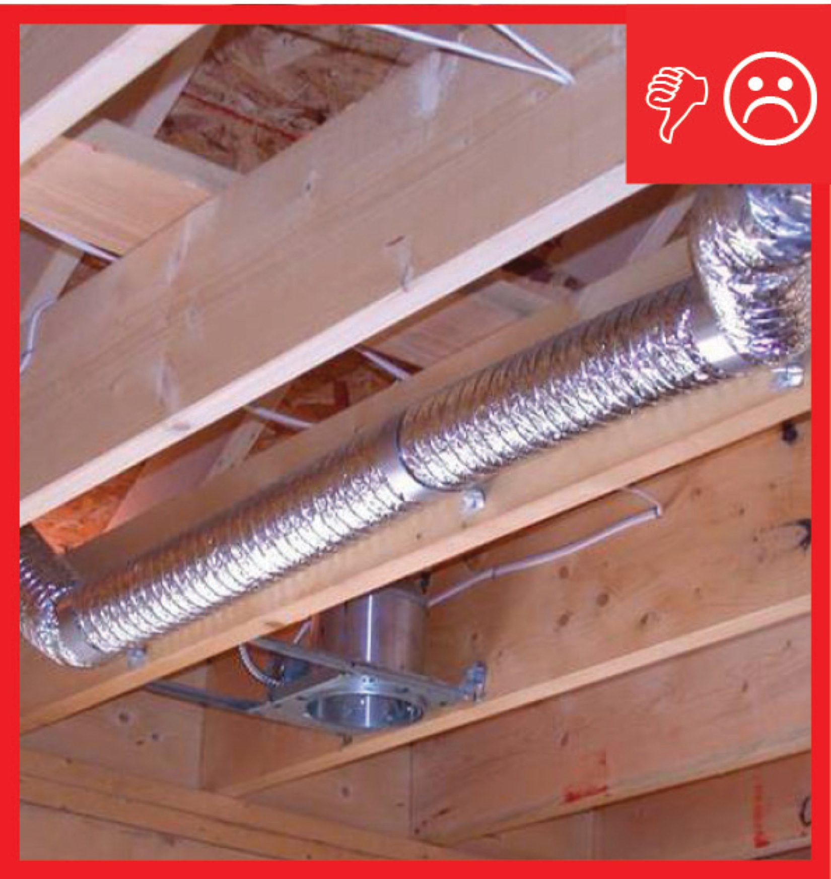
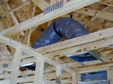
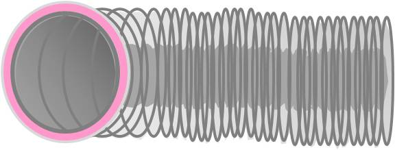
Pulling flex duct taut when installing greatly reduces the amount of friction caused by the ducting
Image
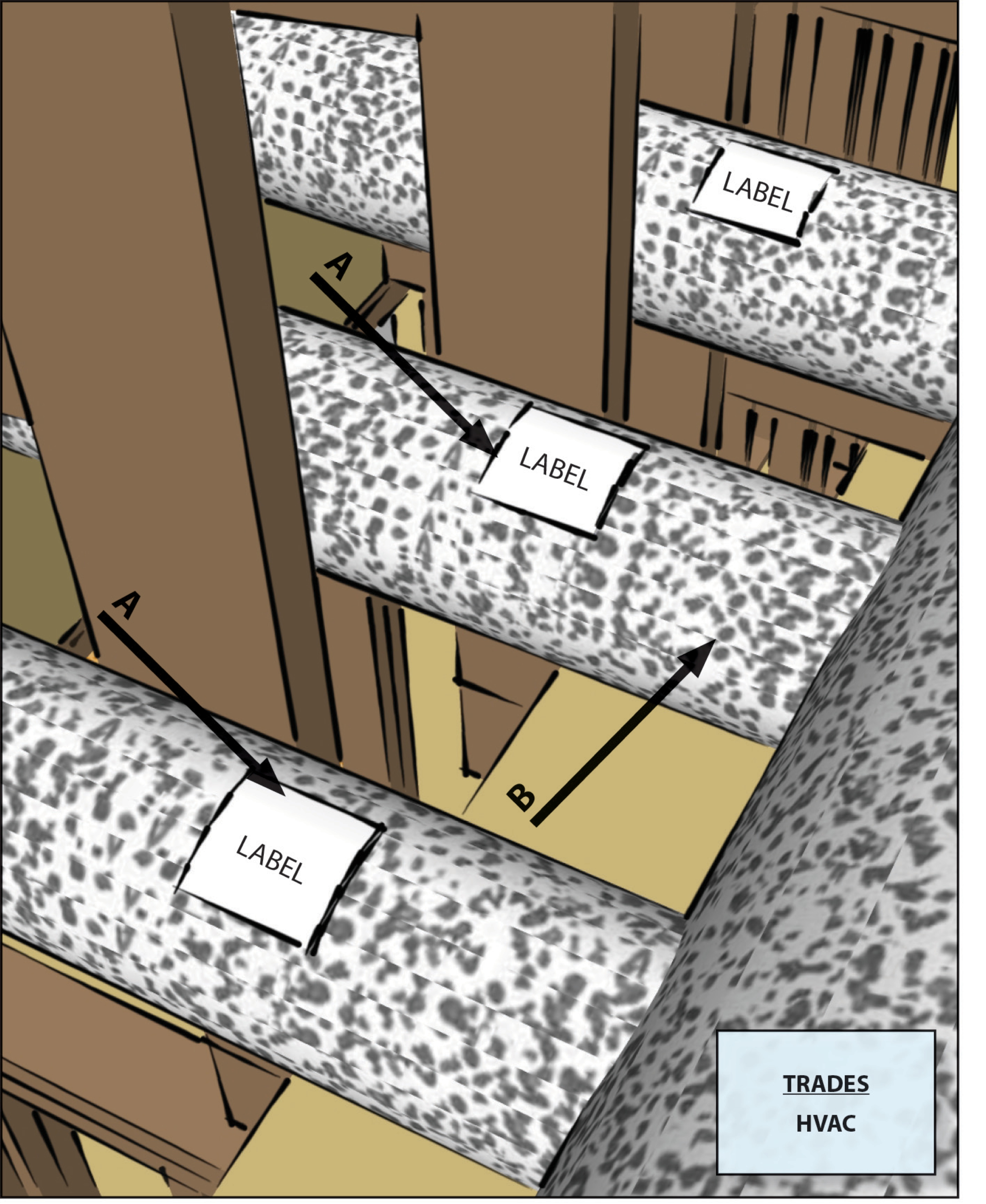
R-6 flexible duct has 2 inches of insulation around the inner liner so a 12-inch duct requires a 16x16-inch chase
Image
Raised ceiling chase sealed with drywall mud
Image
Raised ceiling duct chase is not visible as finished product
Image
Rater-measured duct leakage to outdoors ≤ 4 CFM25 per 100 sq. ft. of conditioned floor area
Image
Image
Image
Image
Image
Image
Right - a dropped ceiling below a taped plywood air barrier provides a service cavity for ducts and wiring.
Image
Right - A heat recovery ventilator supplies all living spaces with fresh air while transferring heat for energy savings.
Image
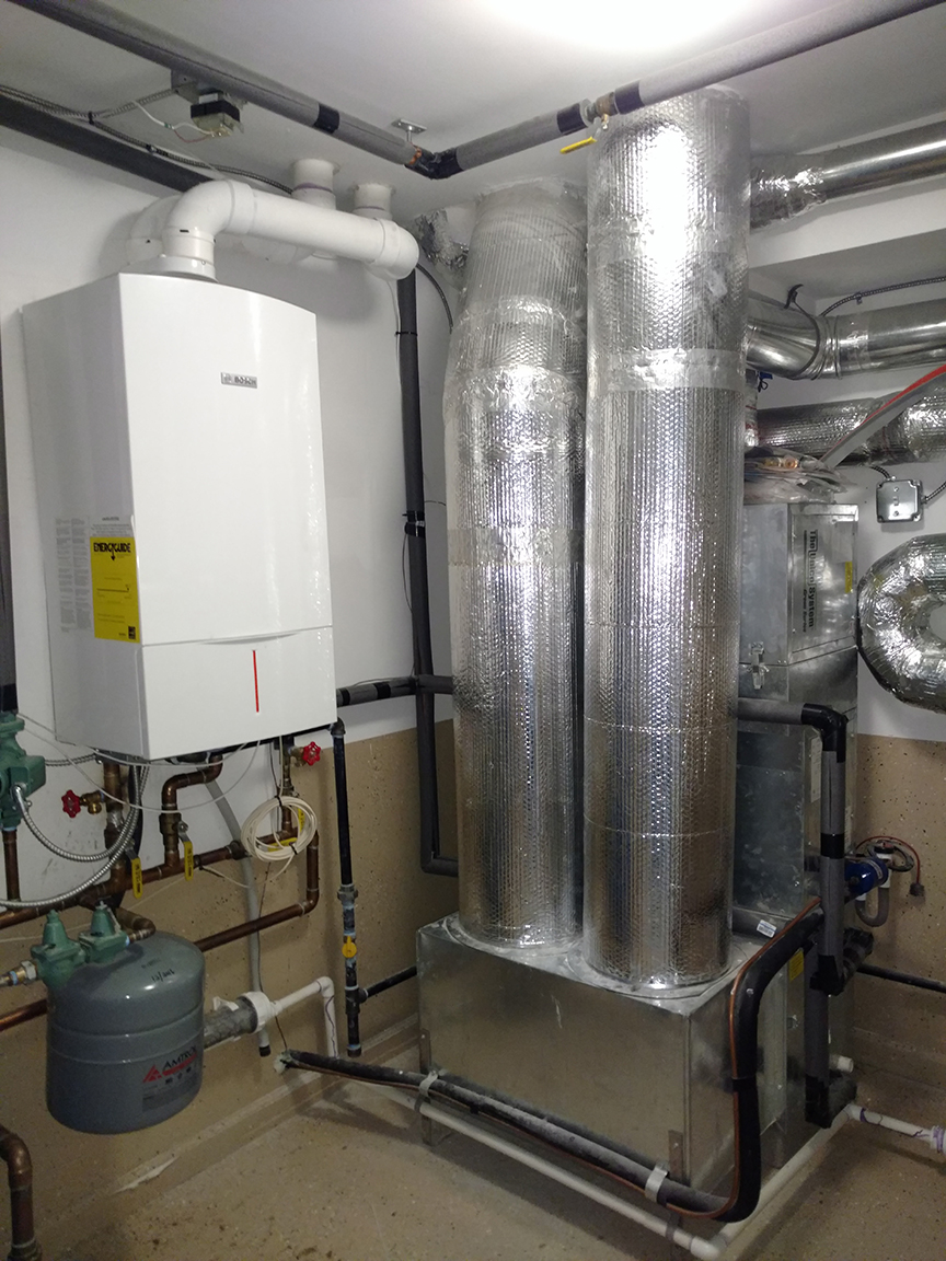
Right - A high-efficiency (95 AFUE) wall-hung gas-fired boiler heats water for the hydro-coil space heating system and also provides a back-up for the solar hot water system.
Image

Right - All seams in the HVAC equipment and ductwork are sealed with mastic; because the HVAC equipment is in the garage, it is an air-sealed closet.
Image
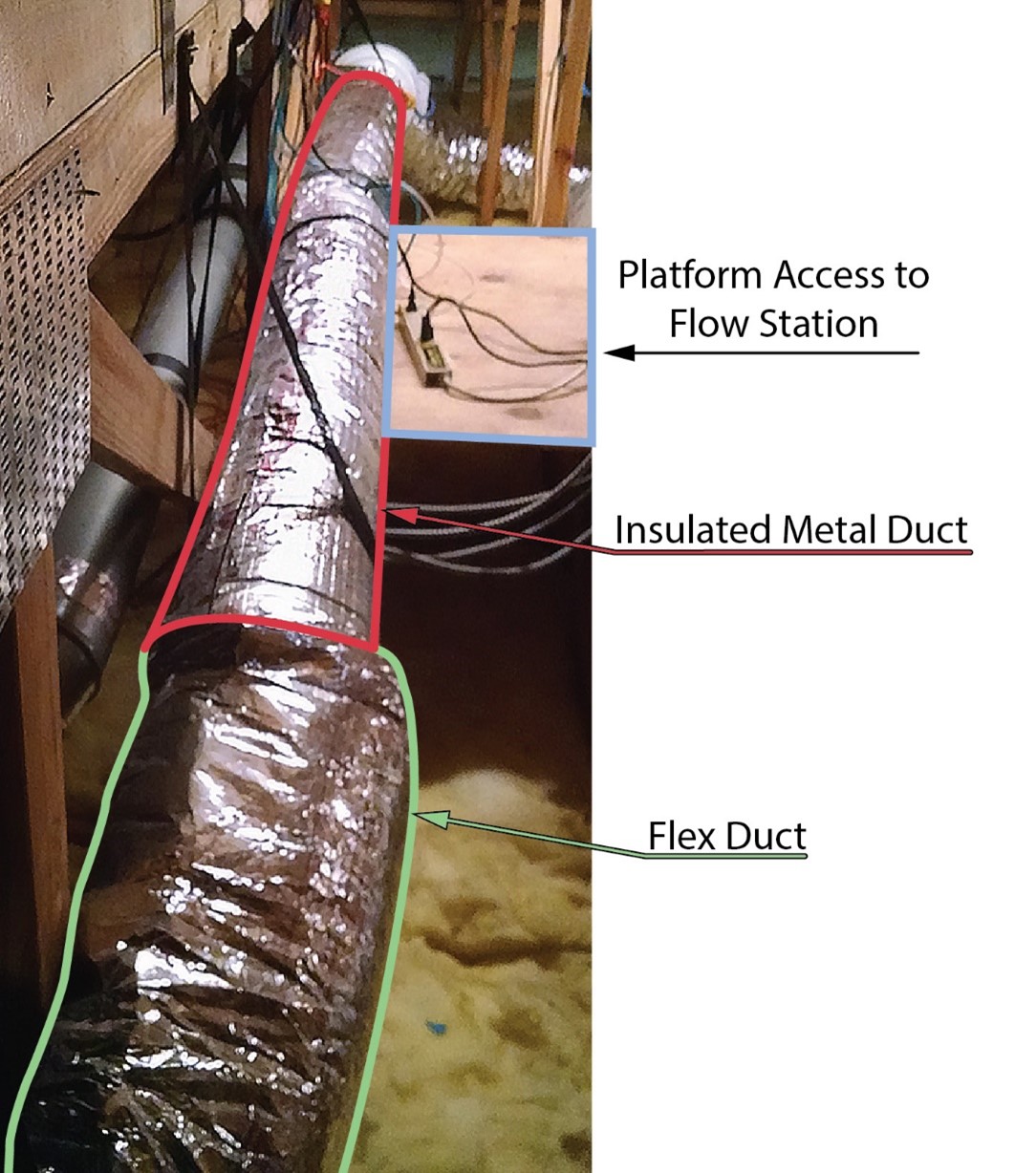
Right - An in-line air flow testing station is installed in a straight section of smooth metal duct (red outline) to determine the air flow rate of a fresh air intake for a whole house ventilation system.
Image
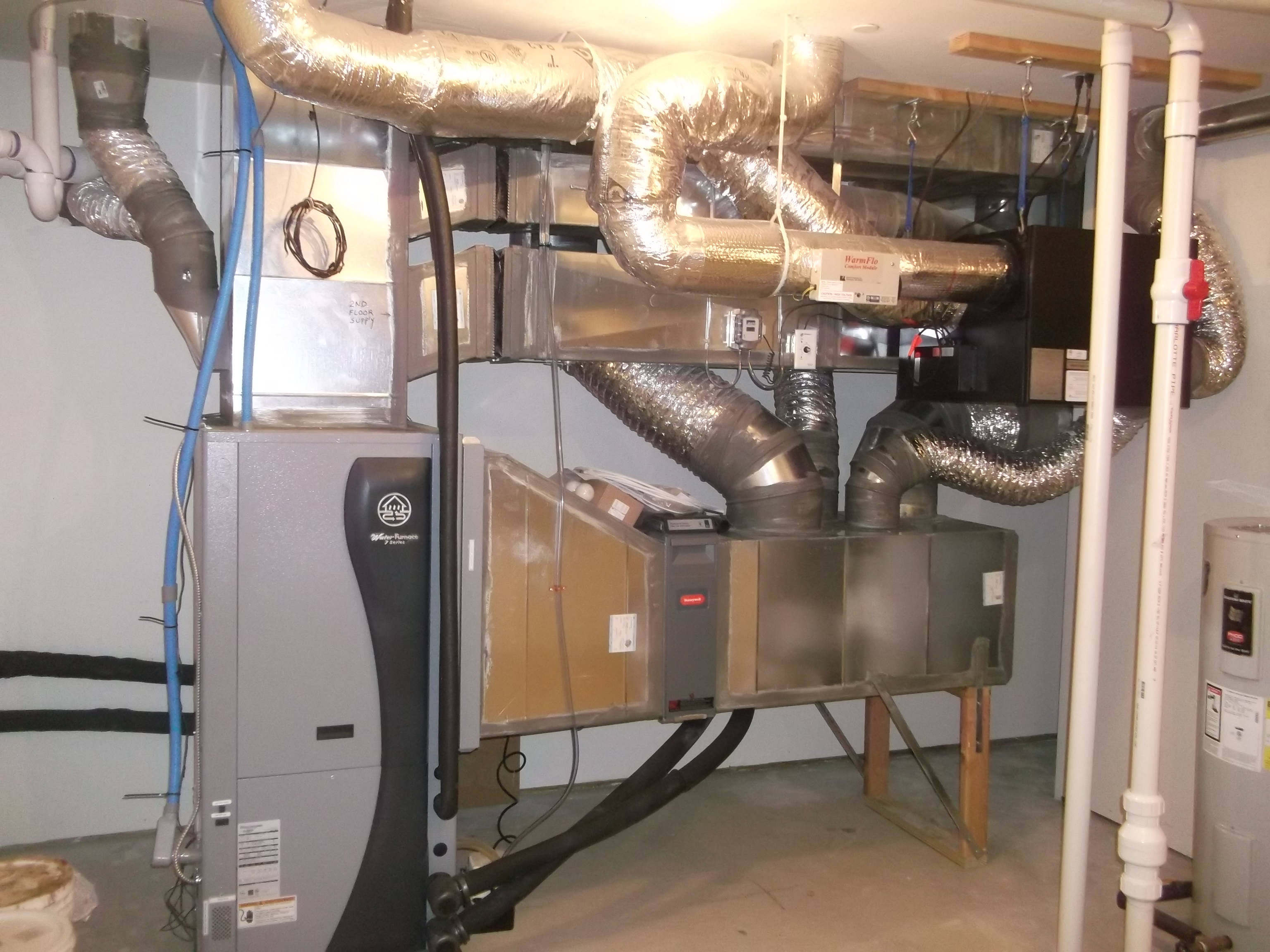
Right - An ultra-efficient (COP 5.7) ground source heat pump provides hot water to an air coil in the central air handler which uses a variable-speed electrically commutated fan motor to distribute conditioned air to the home’s ducts.
Image
Right - Drywall was installed before installing the duct chase to ensure the ducts will be separated from the attic.
Image
Image

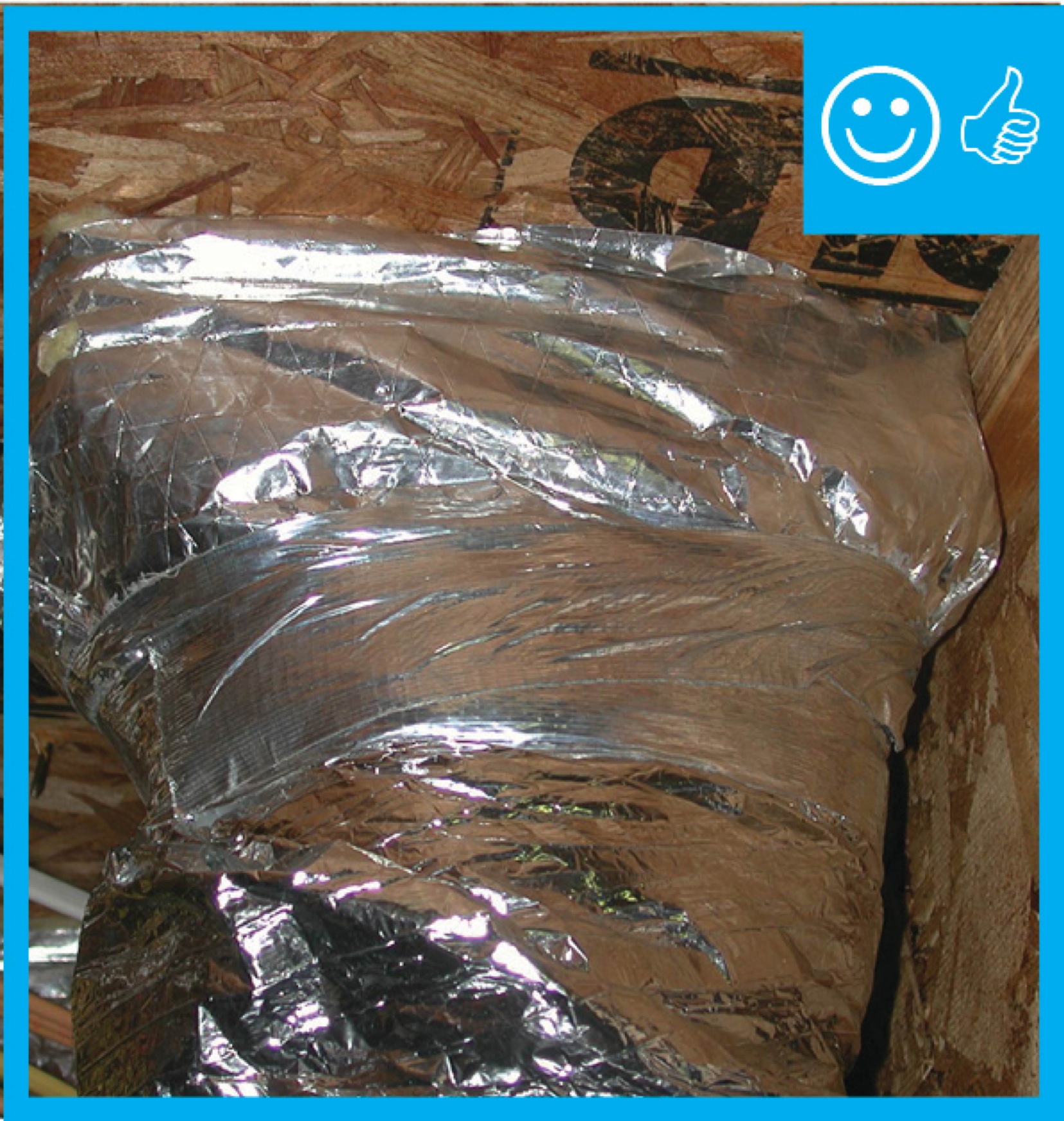
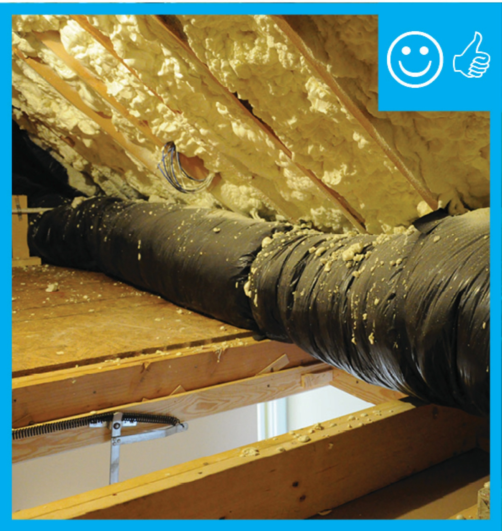
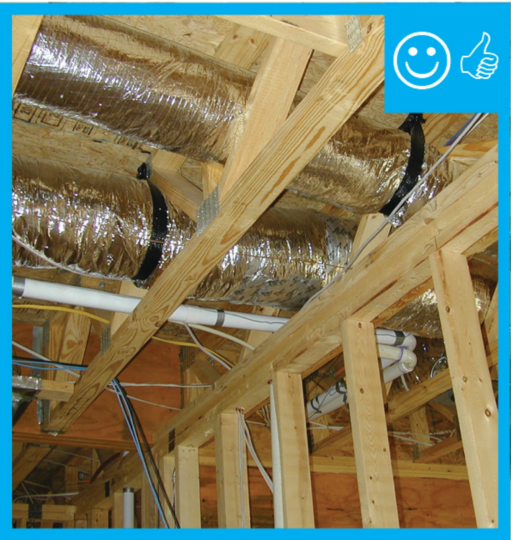
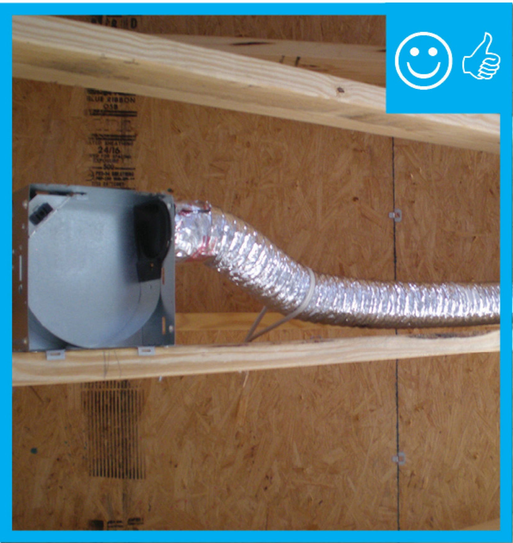
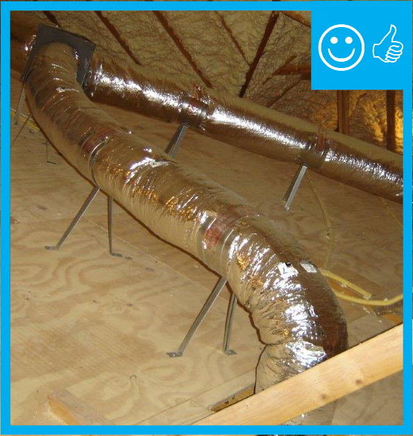
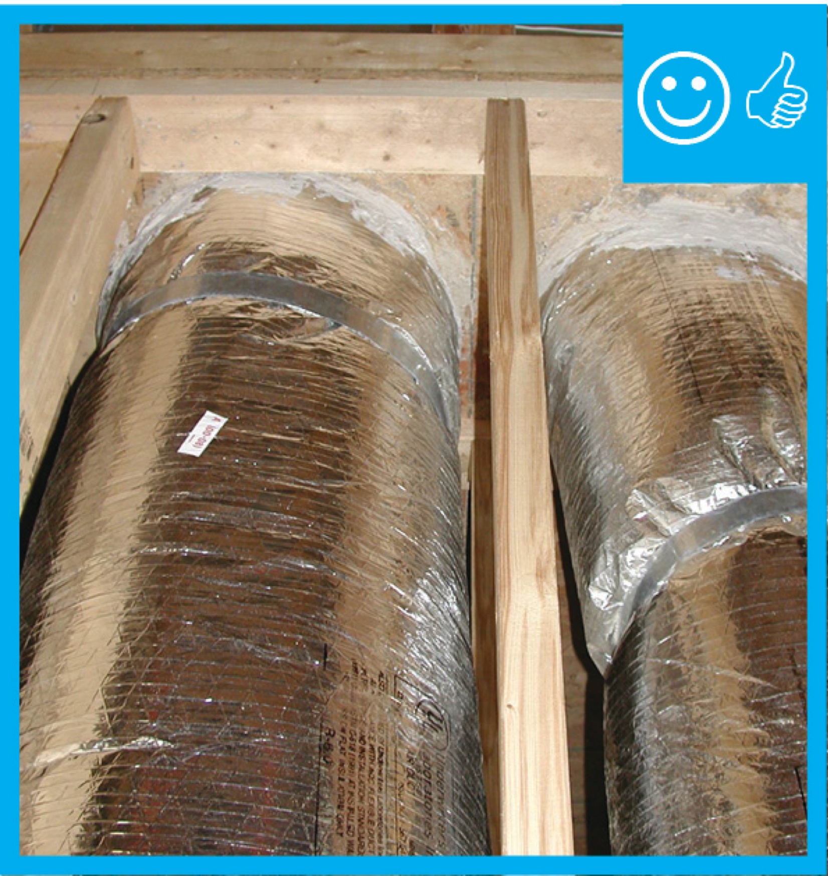
Right - Flex duct installed with adequate support and pulled taut to provide adequate air flow
Image
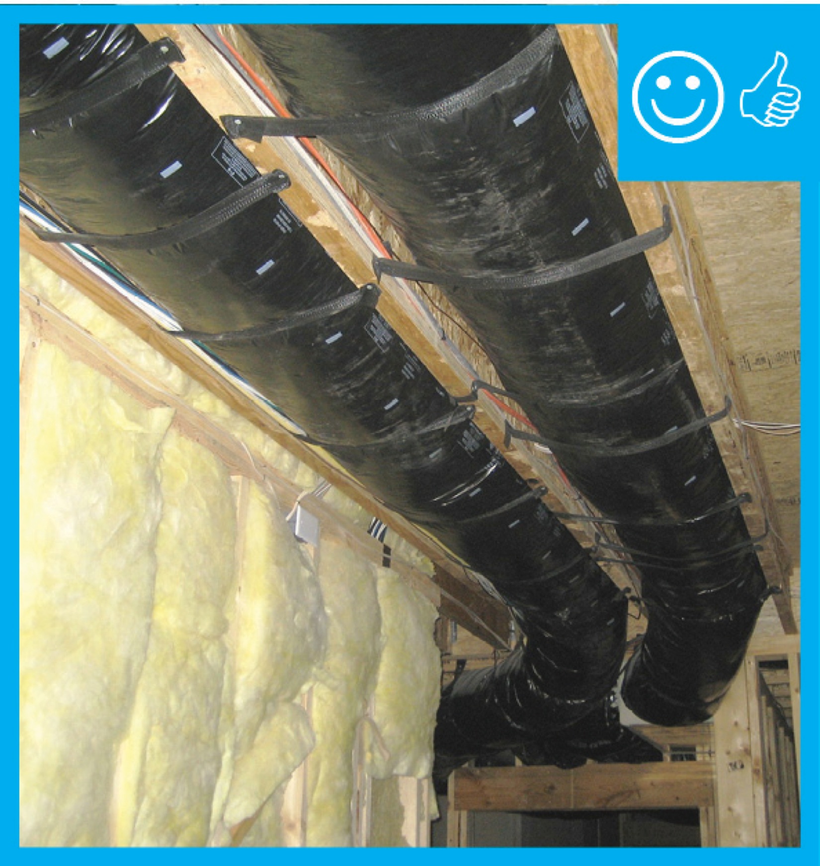
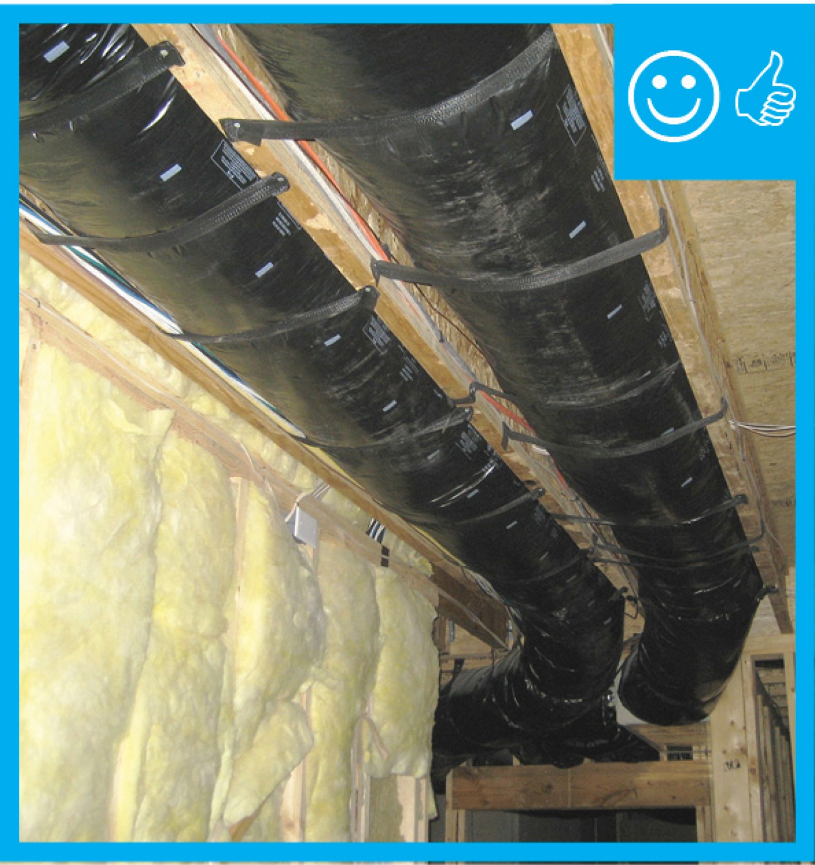
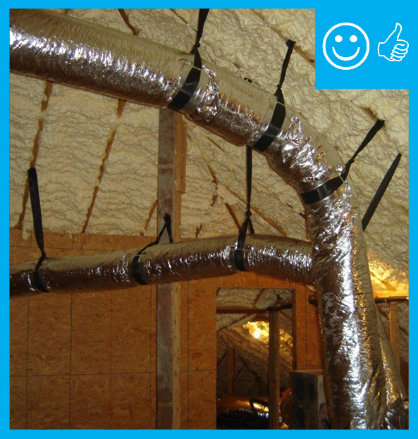
Right - Flex duct installed with frequent supports, straight runs, and gradual turns to allow good air flow
Image
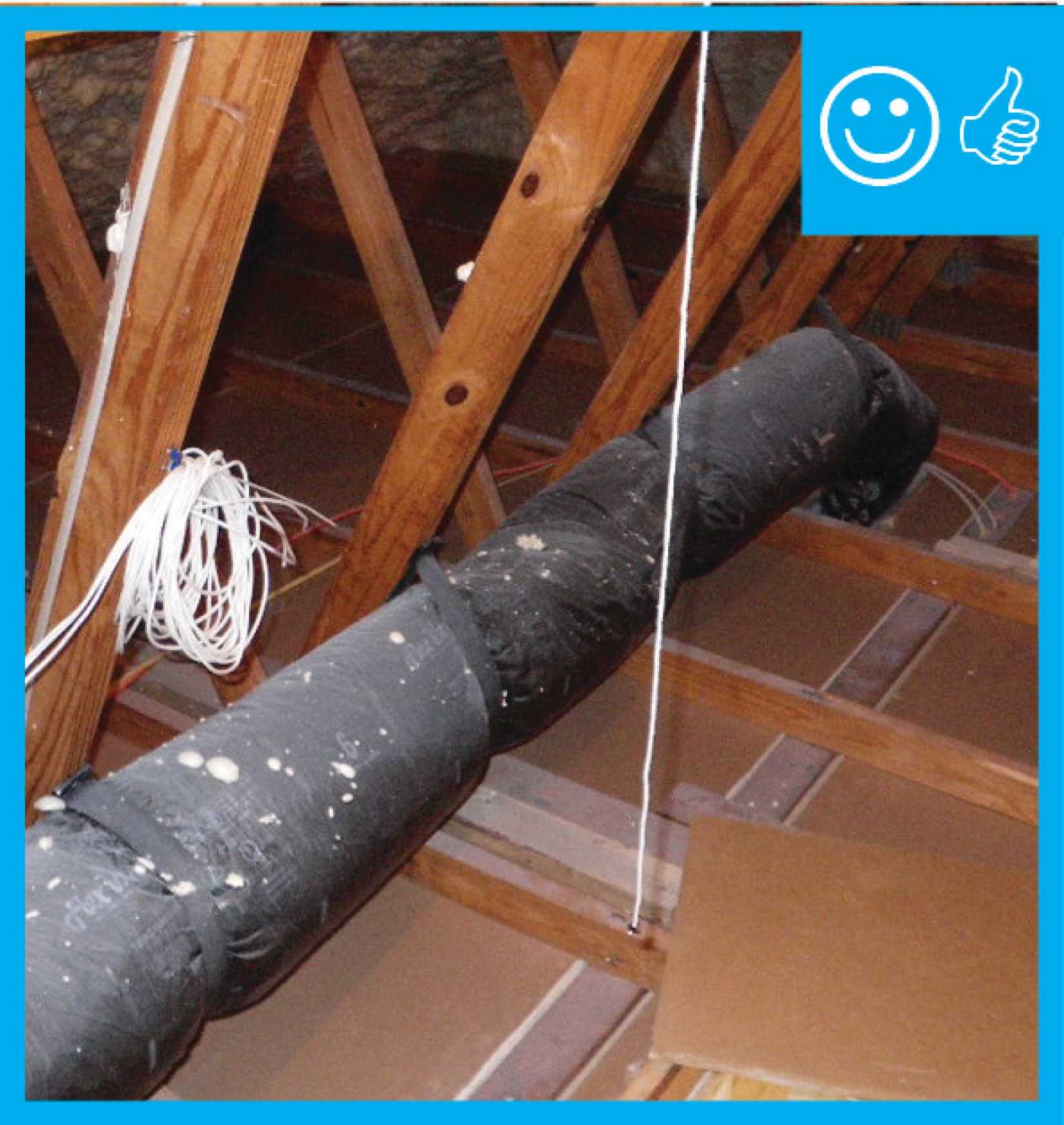
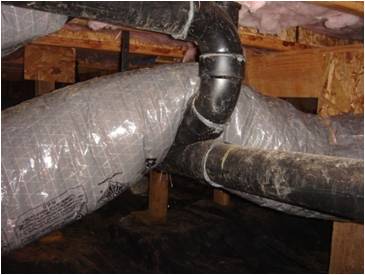
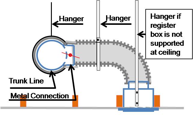
Right - HVAC ducts should be well-supported with minimal bends and pinching.
Image
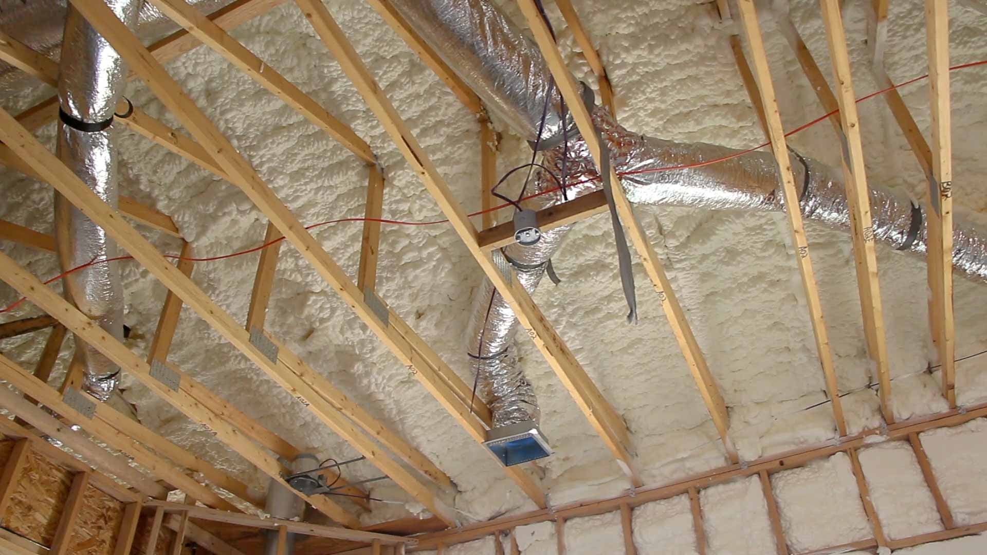
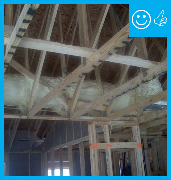
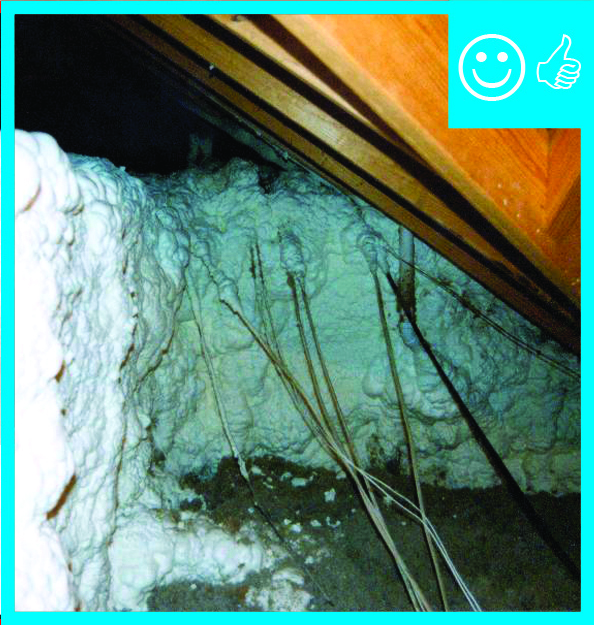
Right - Open-cell polyurethane spray foam to R-28 on underside of roof turns new attic into conditioned space for HVAC.
Image
Image
Image
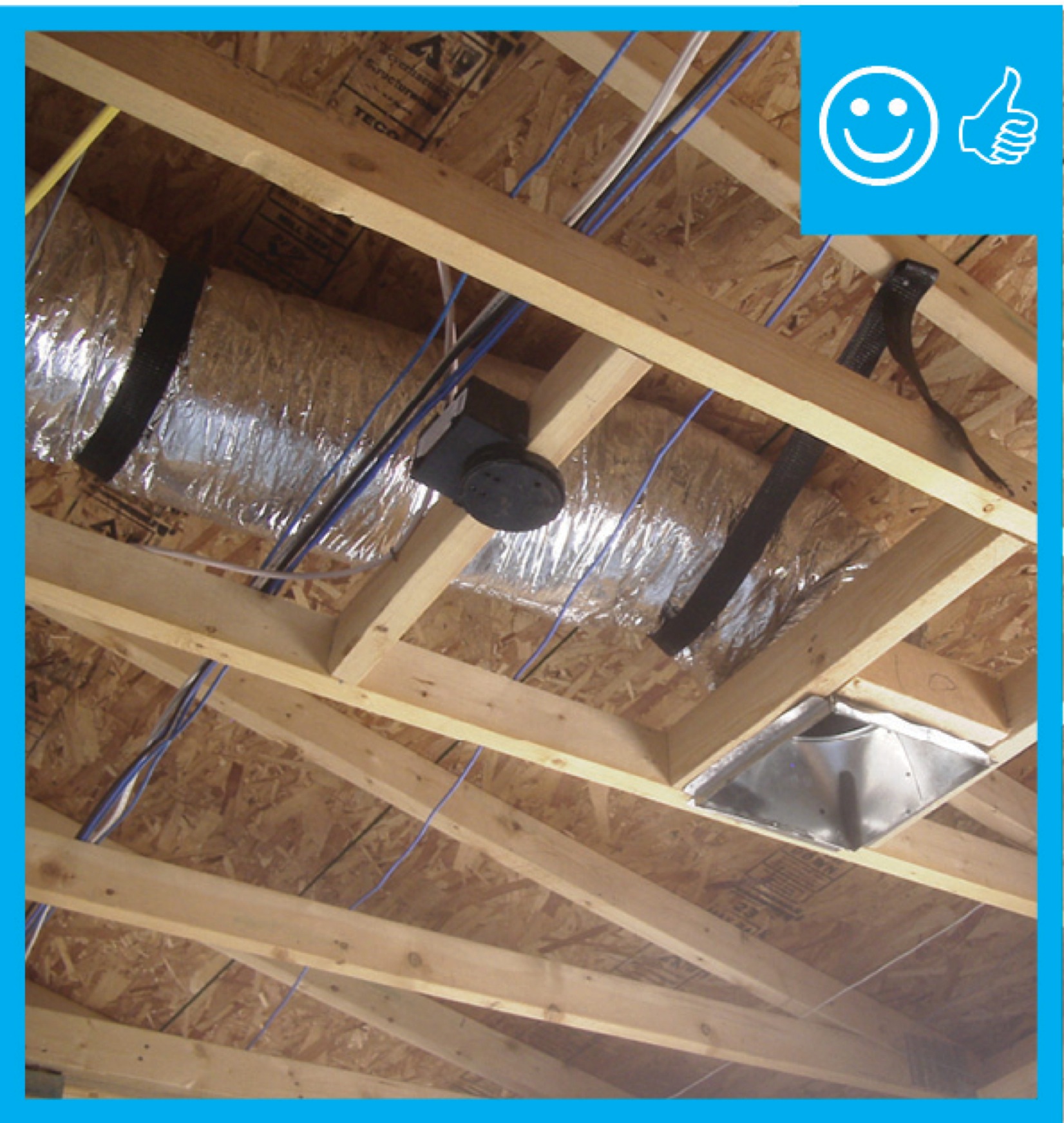
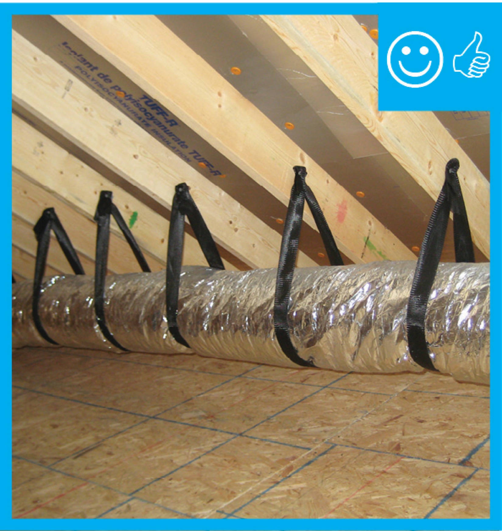
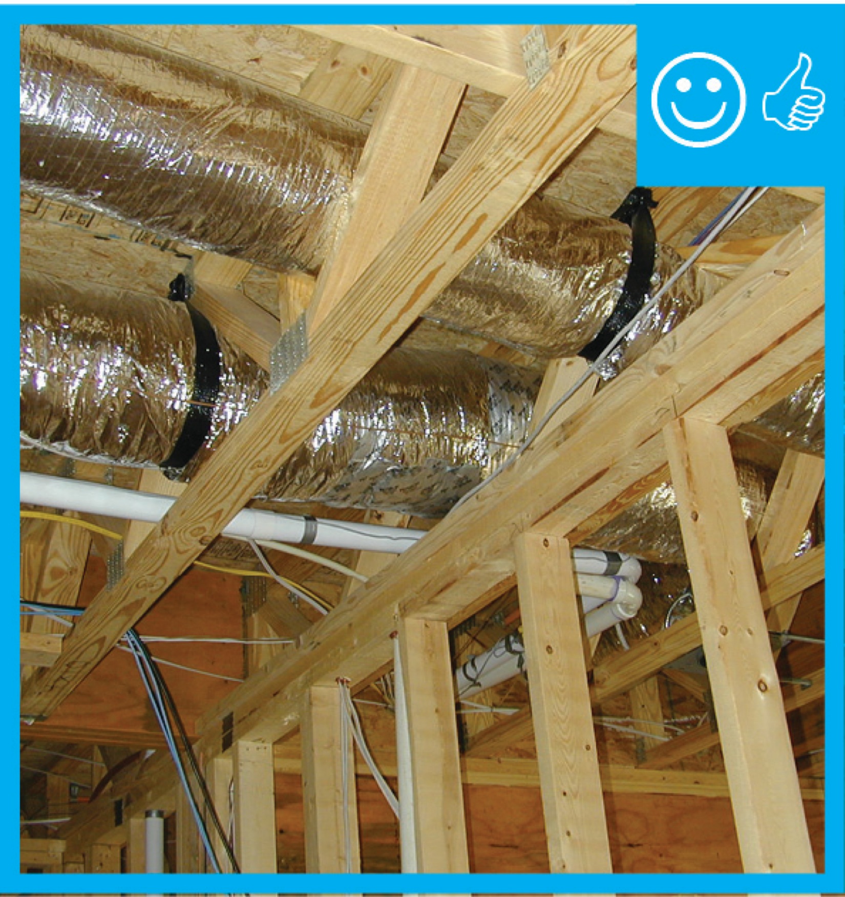
Right - Straps are spaced close enough together to provide adequate support of the flex duct
Image
Right - The butterfly damper of this crawlspace supply register opens when the HVAC fan is running; the damper duct is sealed with mastic and supported by strapping.
Image
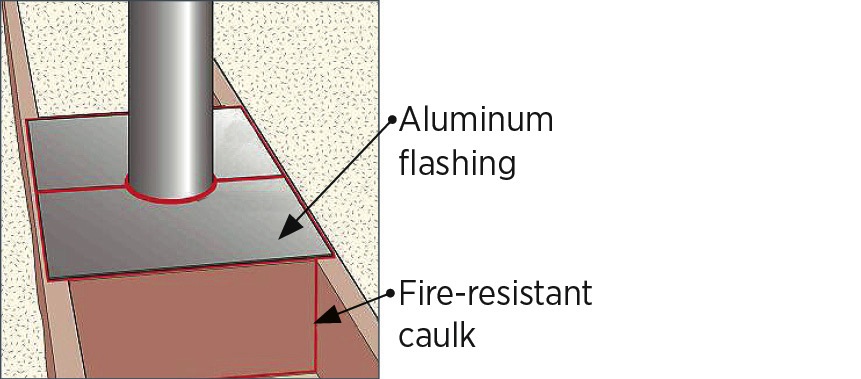
Right - The duct shows redundant sealing including the caulk, tape, and flashing
Image
Image
Right - The HVAC ducts are located in conditioned space in a dropped hallway ceiling with very short duct runs for more efficient delivery.
Image
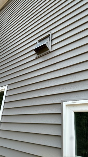
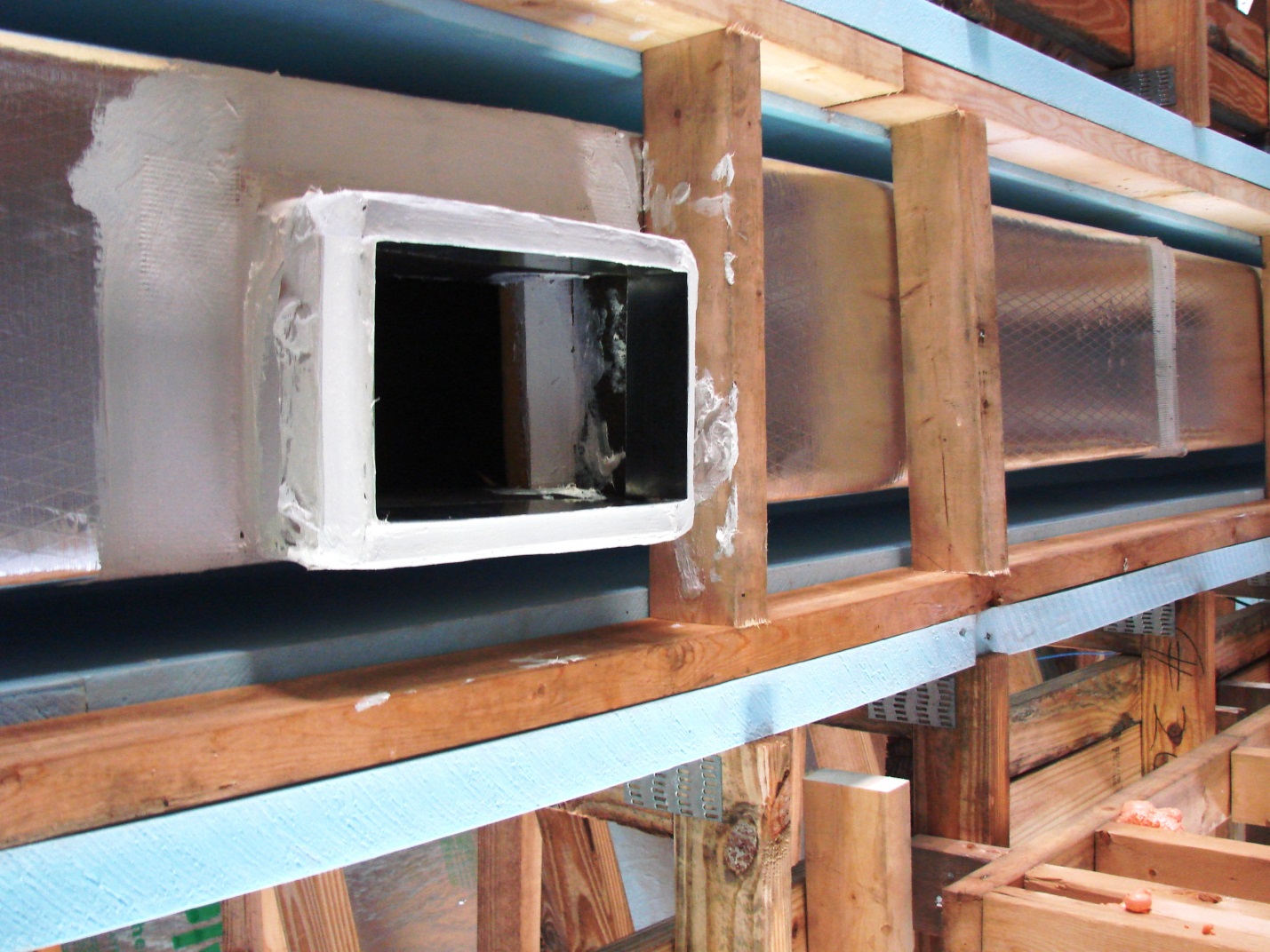
Right - The kitchen exhaust duct termination is integrated aesthetically and functionally with the exterior cladding; however, the opening should be screened to keep out pests.
Image
Image
Right - The precast insulated concrete walls of the basement provide a conditioned space for the high-efficiency (18 SEER, 9.5 HSPF) air-source heat pump, with its variable-speed fan, five-stage compressor, and MERV 11 filter.
Image
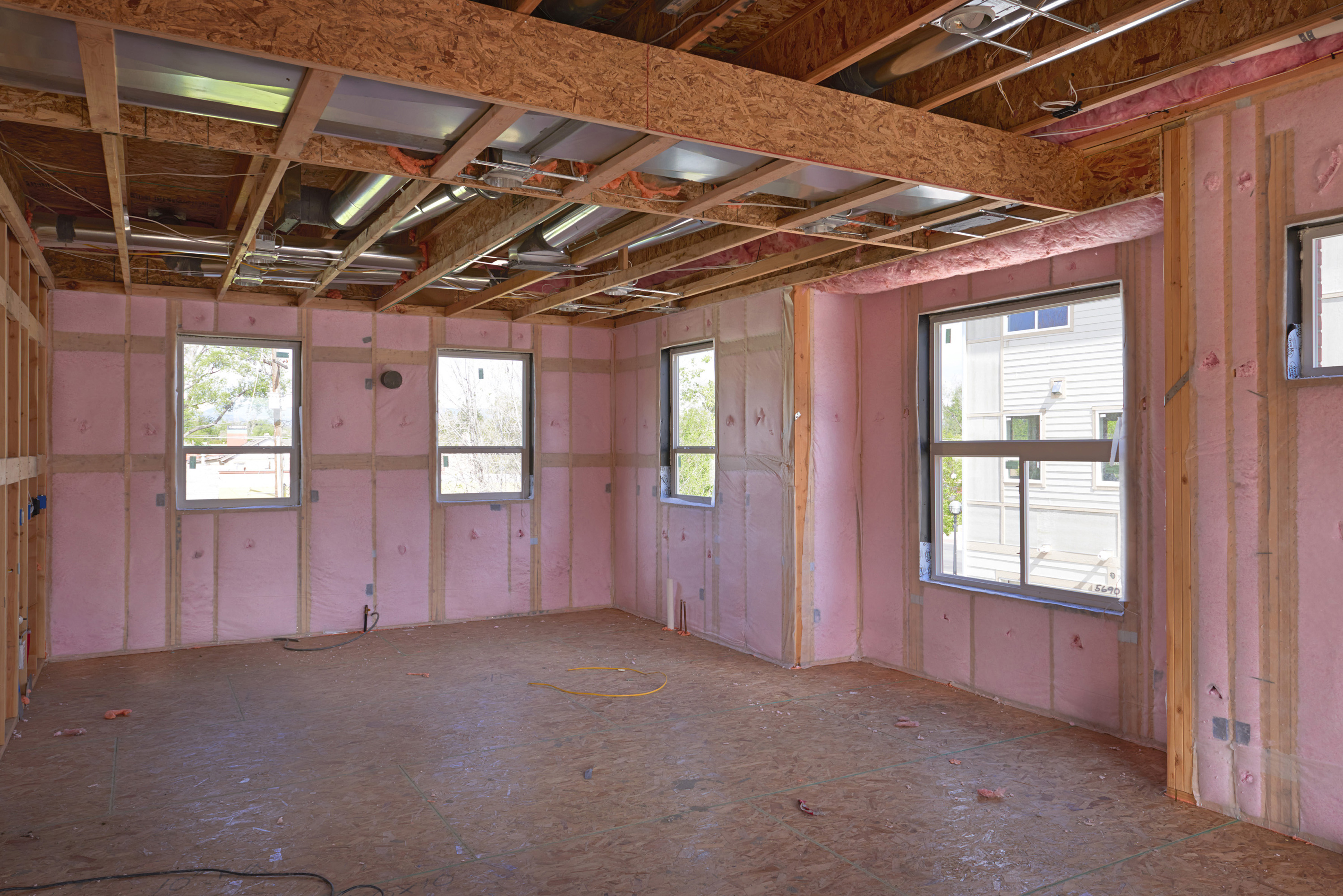
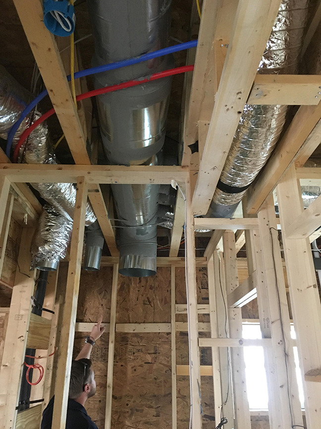
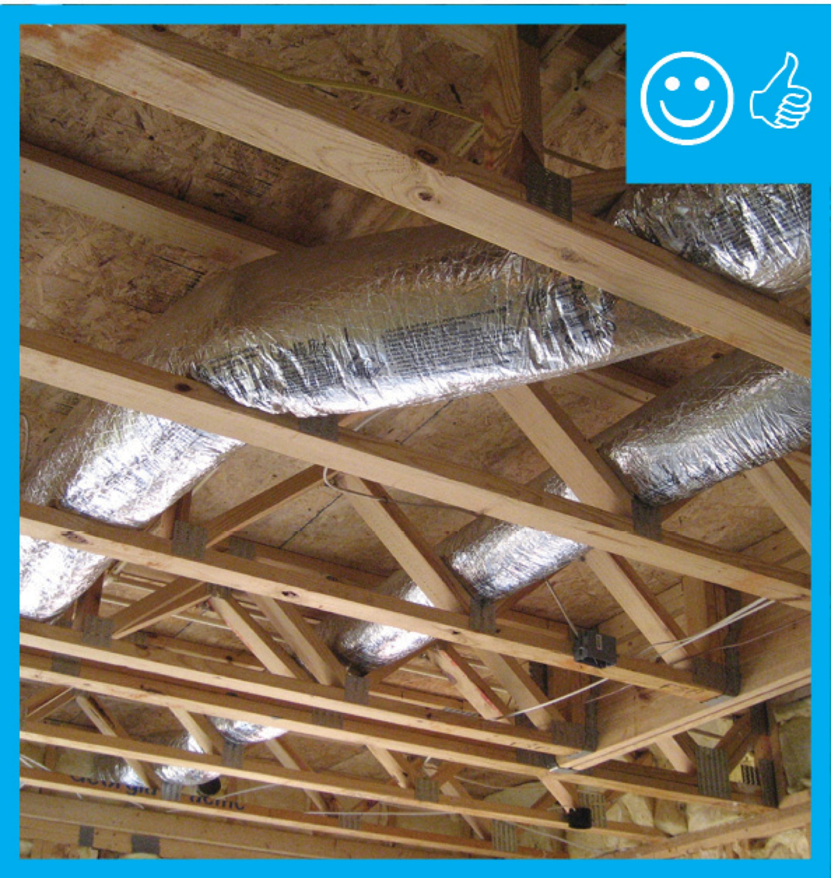
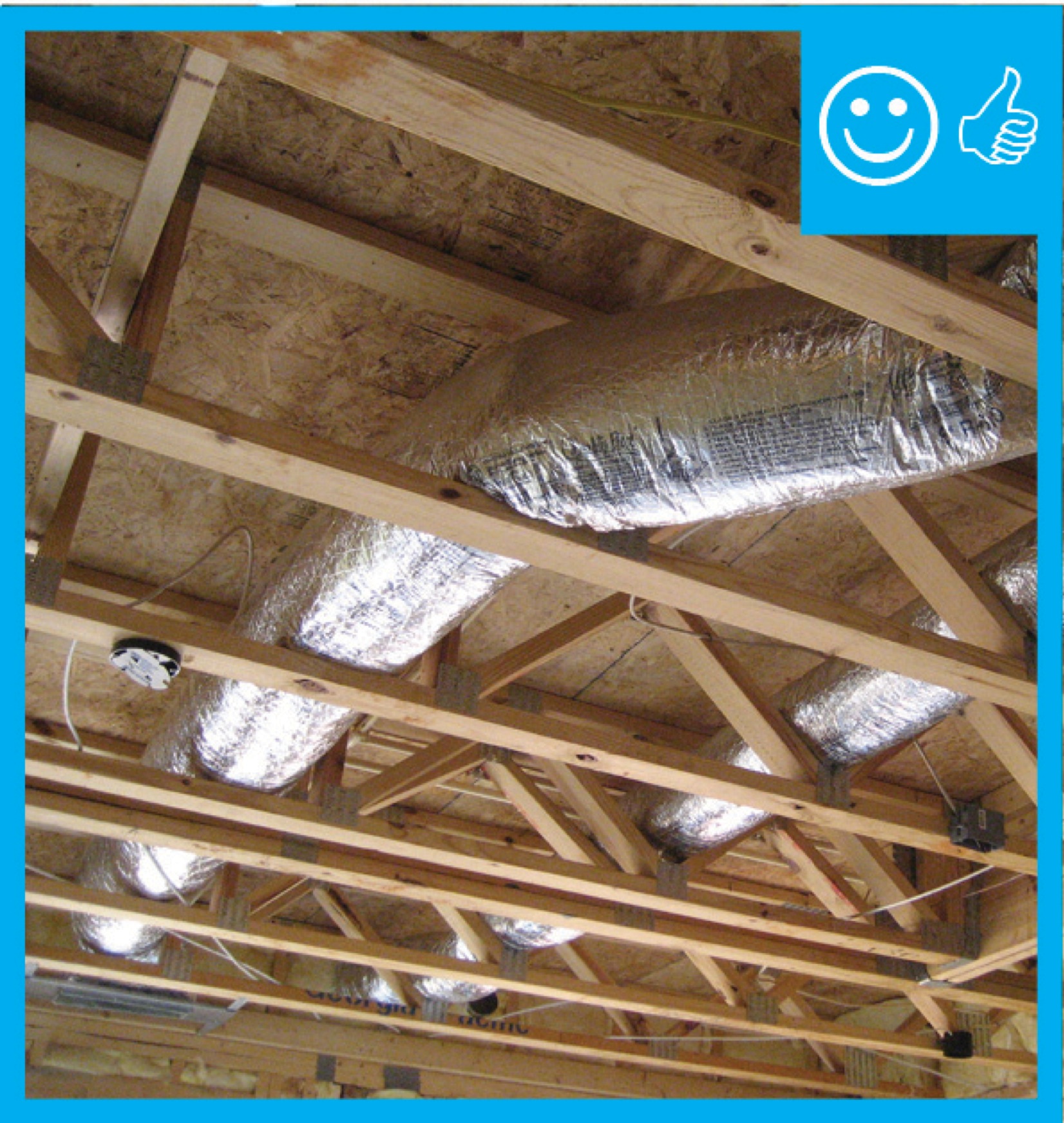
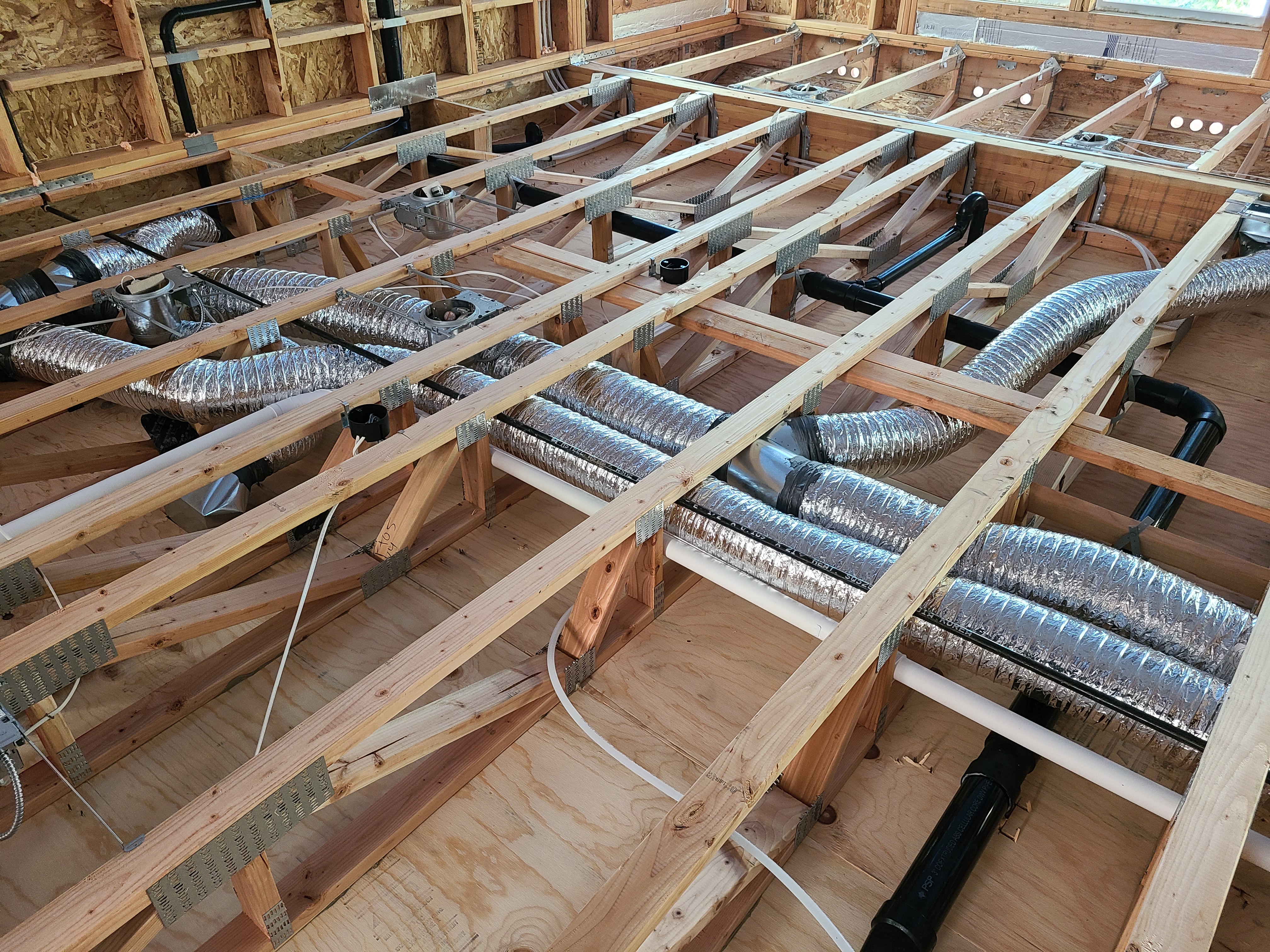
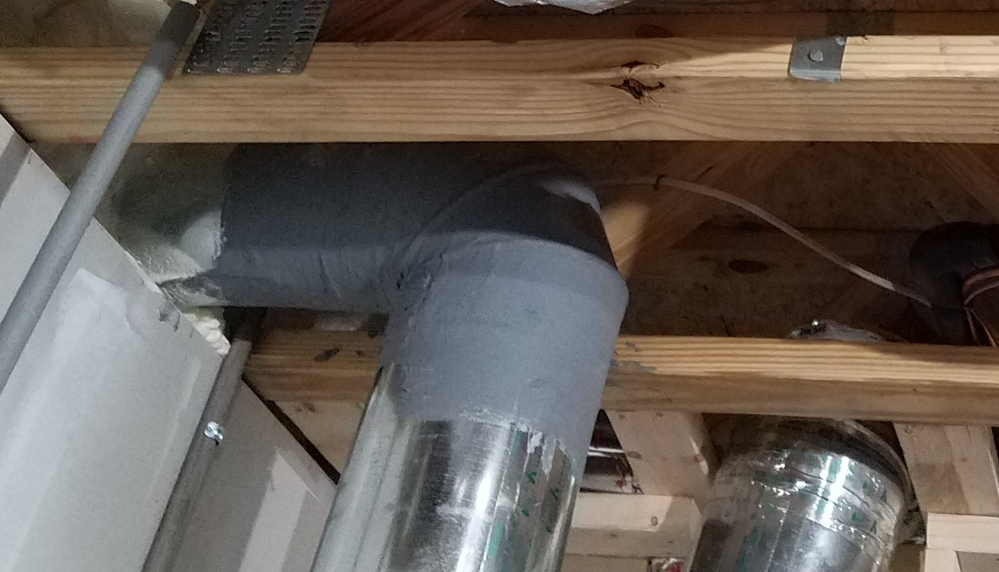
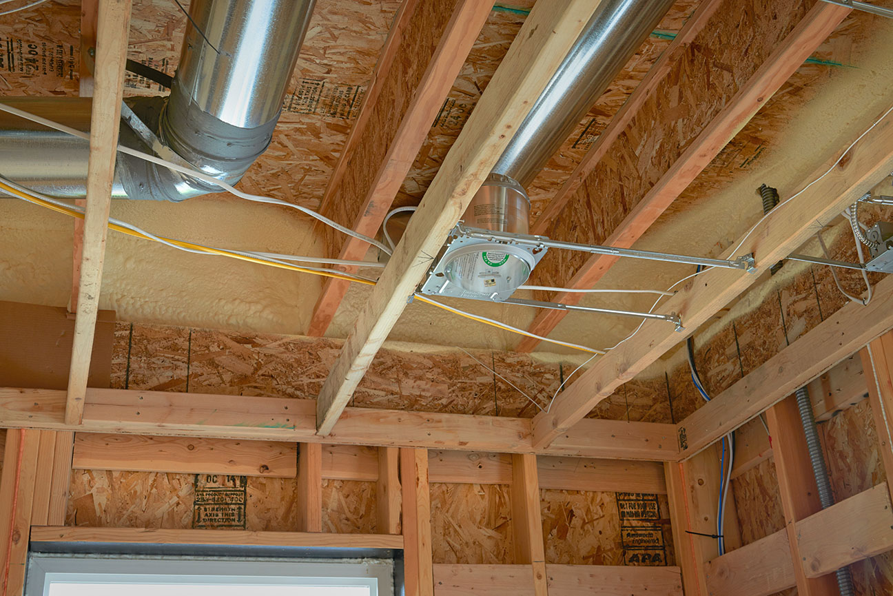
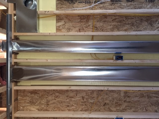
Right - The rigid metal HVAC ducting is installed between the floor joists rather than in an unconditioned attic or crawl space to minimize heat loss.
Image
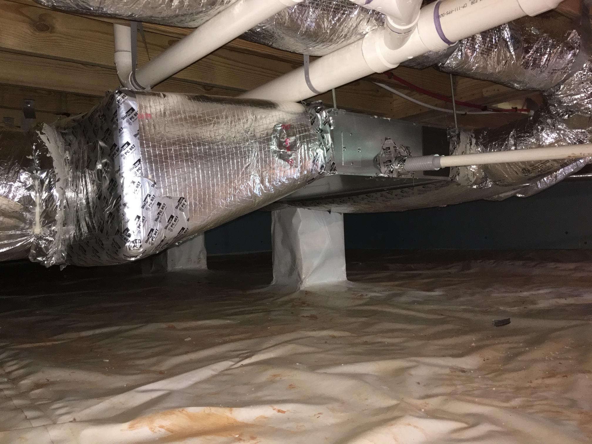
Right - the vapor barrier is extended up the sides of the piers in this crawlspace, which is sealed and insulated to house the HVAC ducts.
Image
Right - This duct penetration is properly flashed and integrated with the taped, foil-faced foam sheathing layer, which serves as the air and water barrier
Image
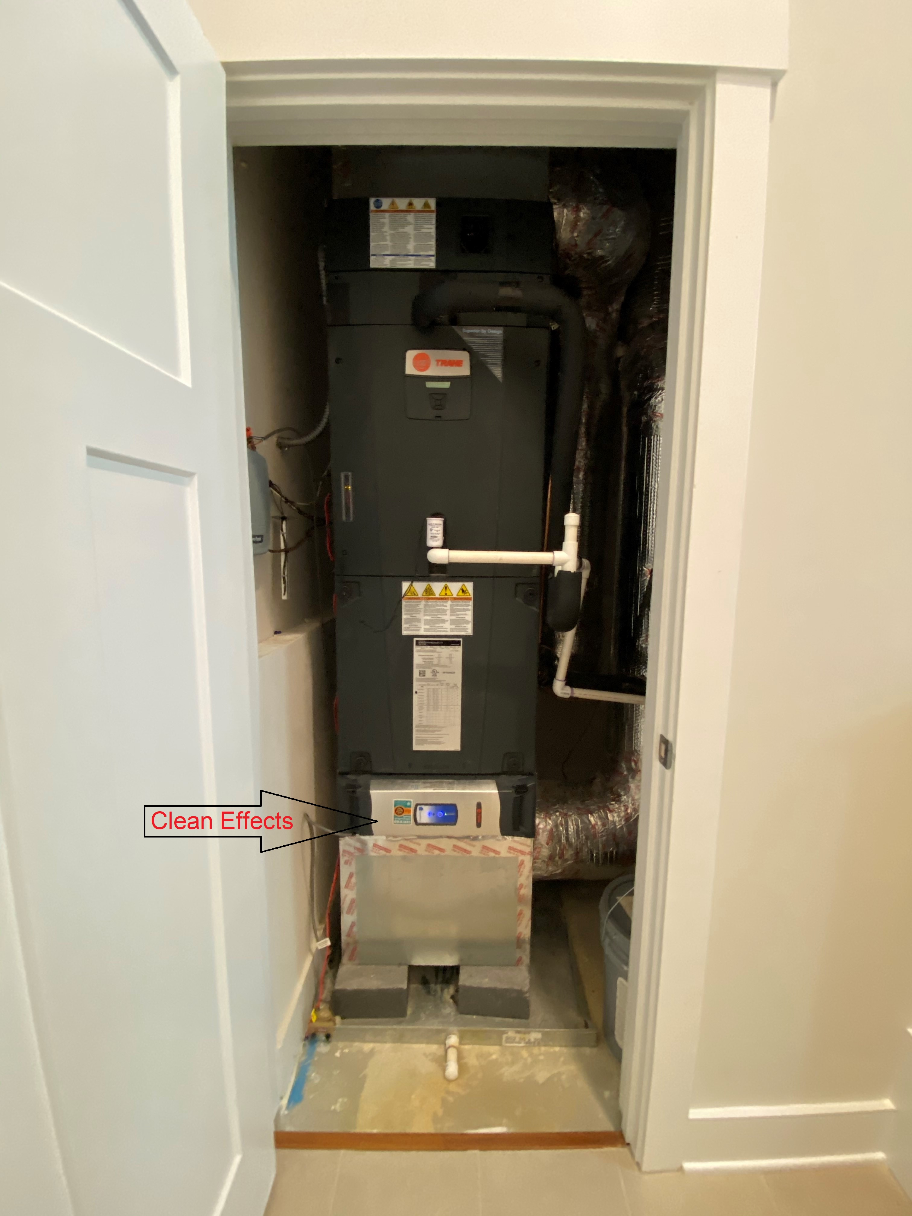
Right - This heat pump is located in a closet inside the home and all ducts are located within conditioned space between floors.
Image
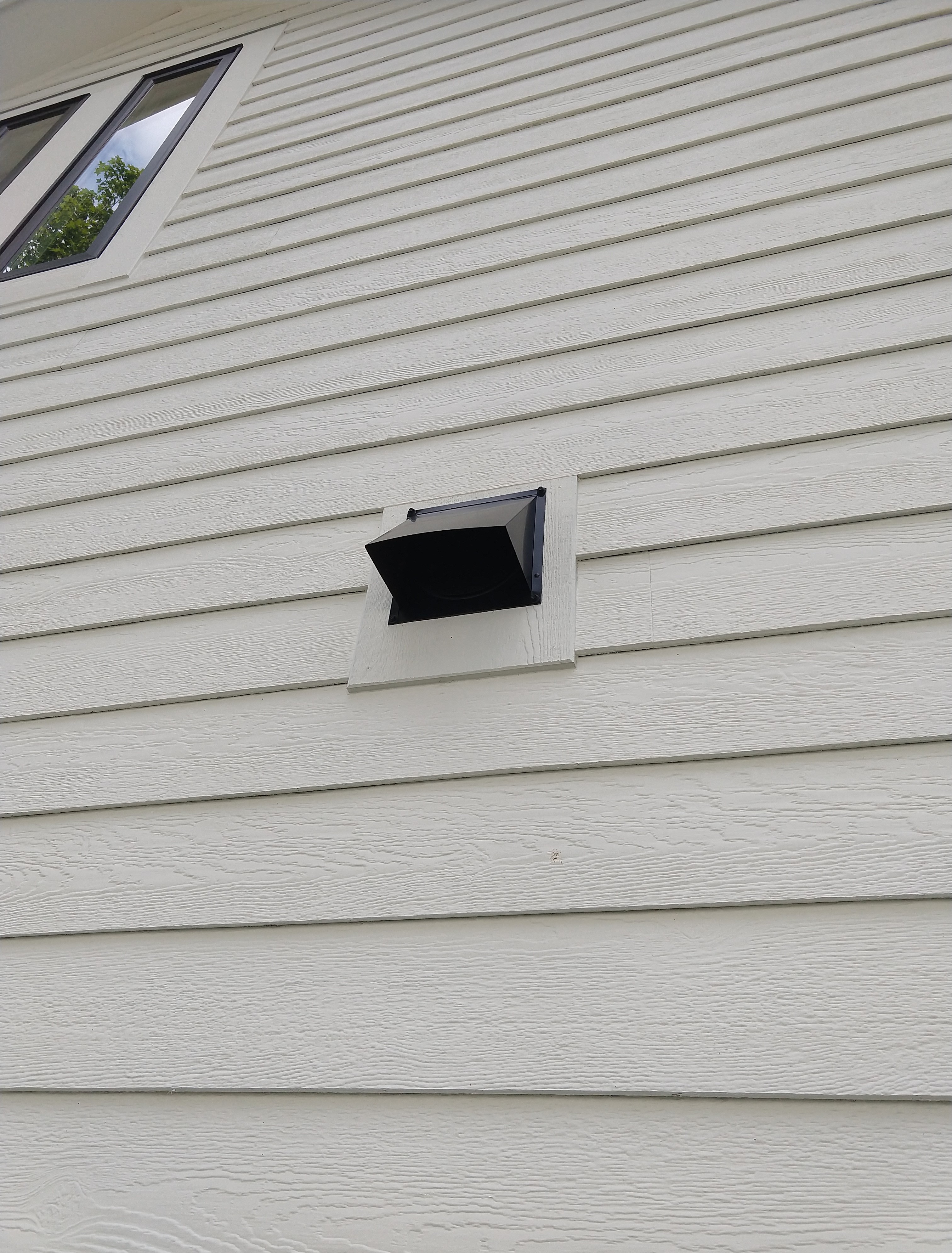
Right - This kitchen exhaust duct termination is integrated aesthetically and functionally with the exterior cladding.
Image
Right – a booster fan was installed in this long dryer duct to increase air flow and help prevent the duct from being clogged with lint
Image
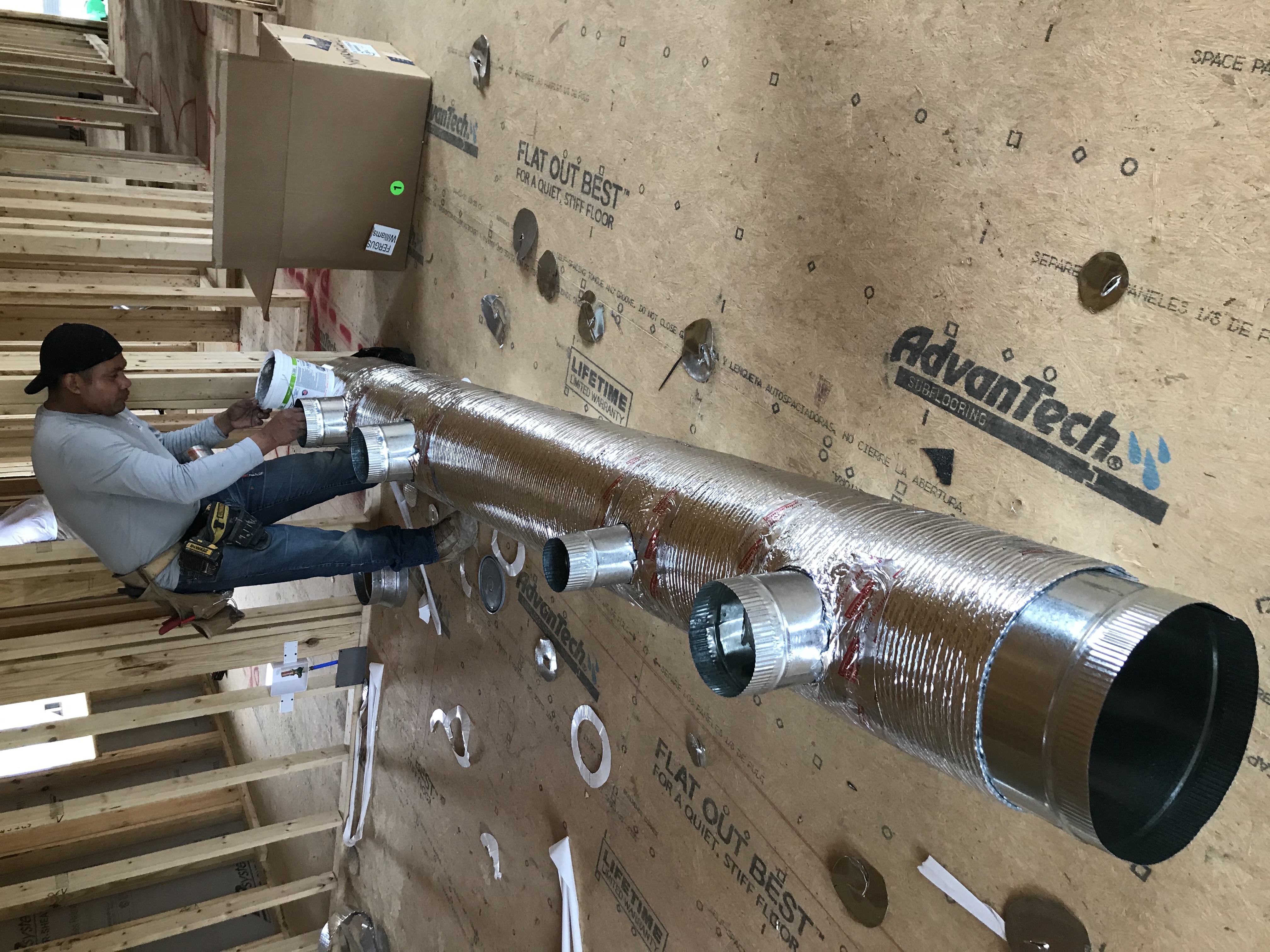
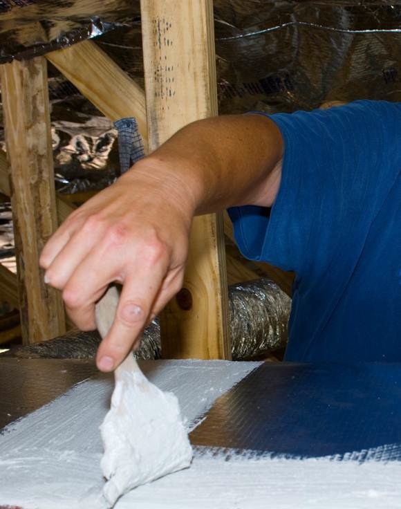
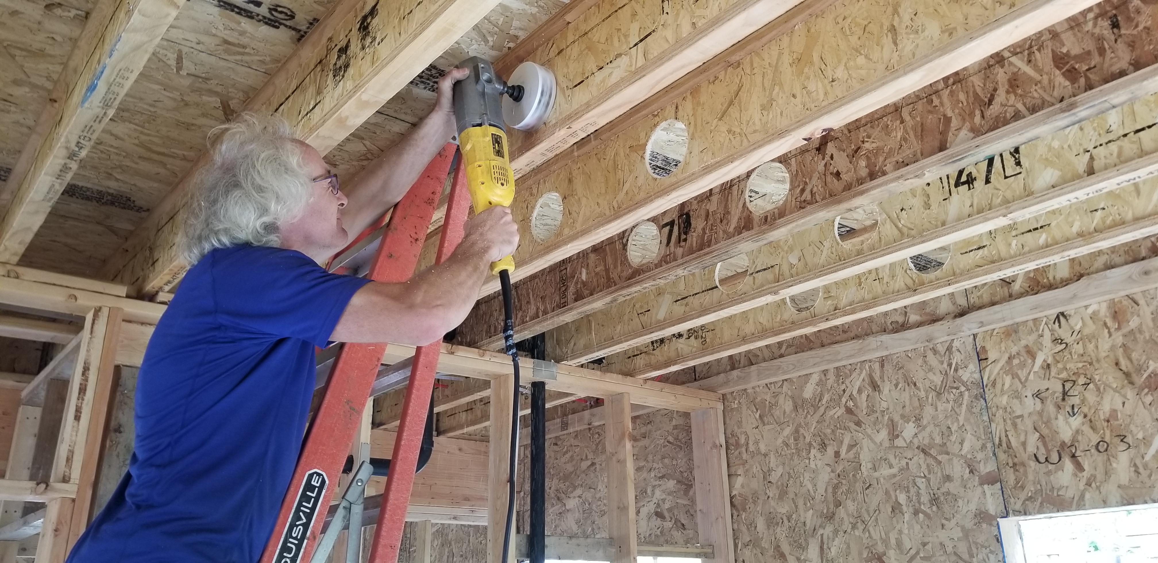
Right – A contractor installs mastic in branch duct take offs to air seal the seams where they attach to the trunk duct.
Image
Image
Right – All supply ducts in this home were located in conditioned space; any return ducts that were located in the attic were insulated with closed-cell spray foam and buried in the blown-in attic insulation to prevent air leakage and heat loss.
Image
Right – Batt insulation provides additional insulation for the home’s main duct chase.
Image
Right – Chase capped with rigid air barrier and duct work penetrations properly sealed
Image
Image

Image
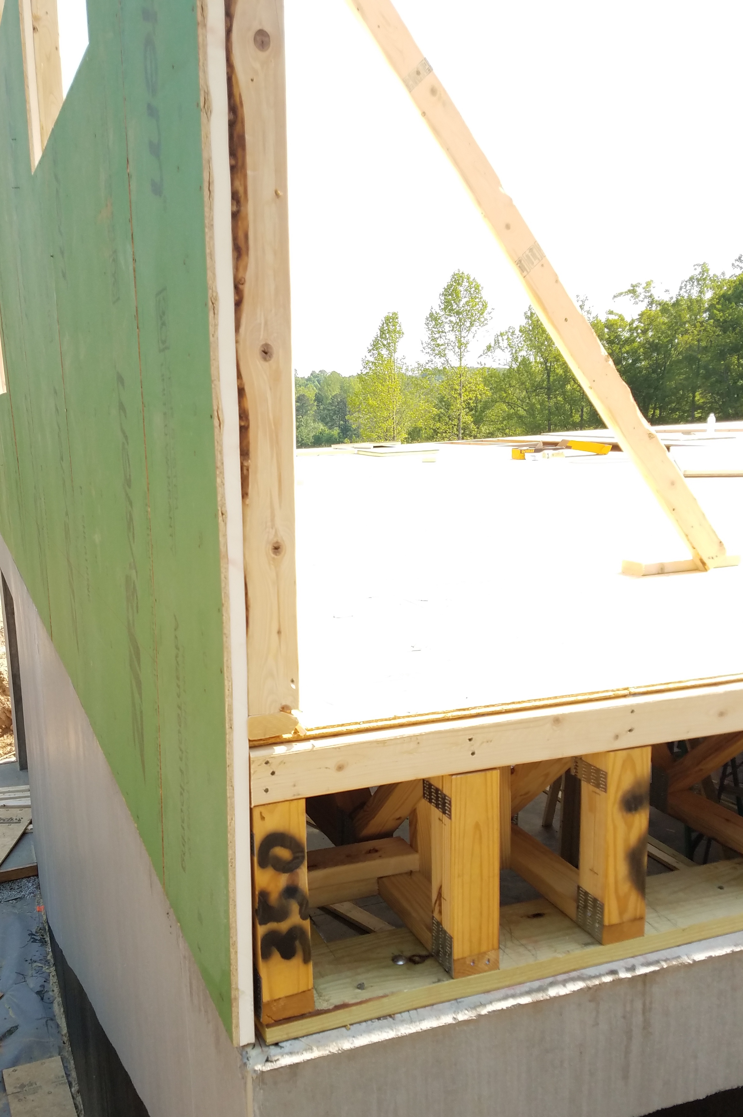
Right – Engineered open-web floor joists provide space between floors for ducting.
Image
Image
Image

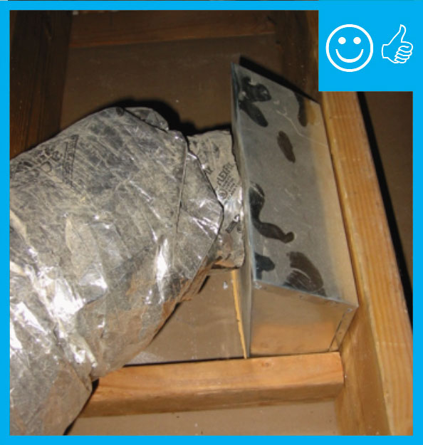
Right – Flex duct is properly connected to metal duct with a duct tie and connection is mastic sealed
Image
Image
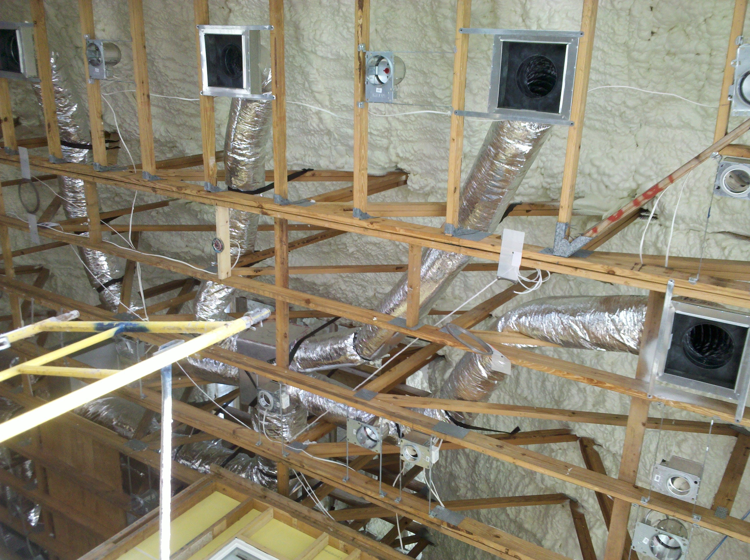
Right – Flex ducts are properly supported with straps that don’t pinch the insulation; closed-cell spray foam will be applied to the underside of the roof deck of this hot-humid climate home to provide an insulated attic space for the HVAC ducts.
Image
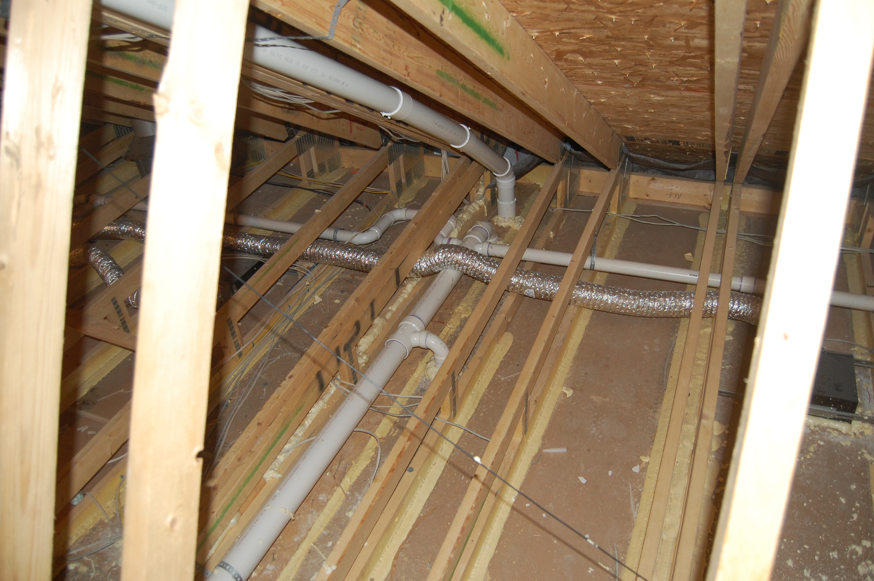
Right – Holes were drilled into the I joists between floors to run the small-diameter HRV ducts.
Image

Image
Image
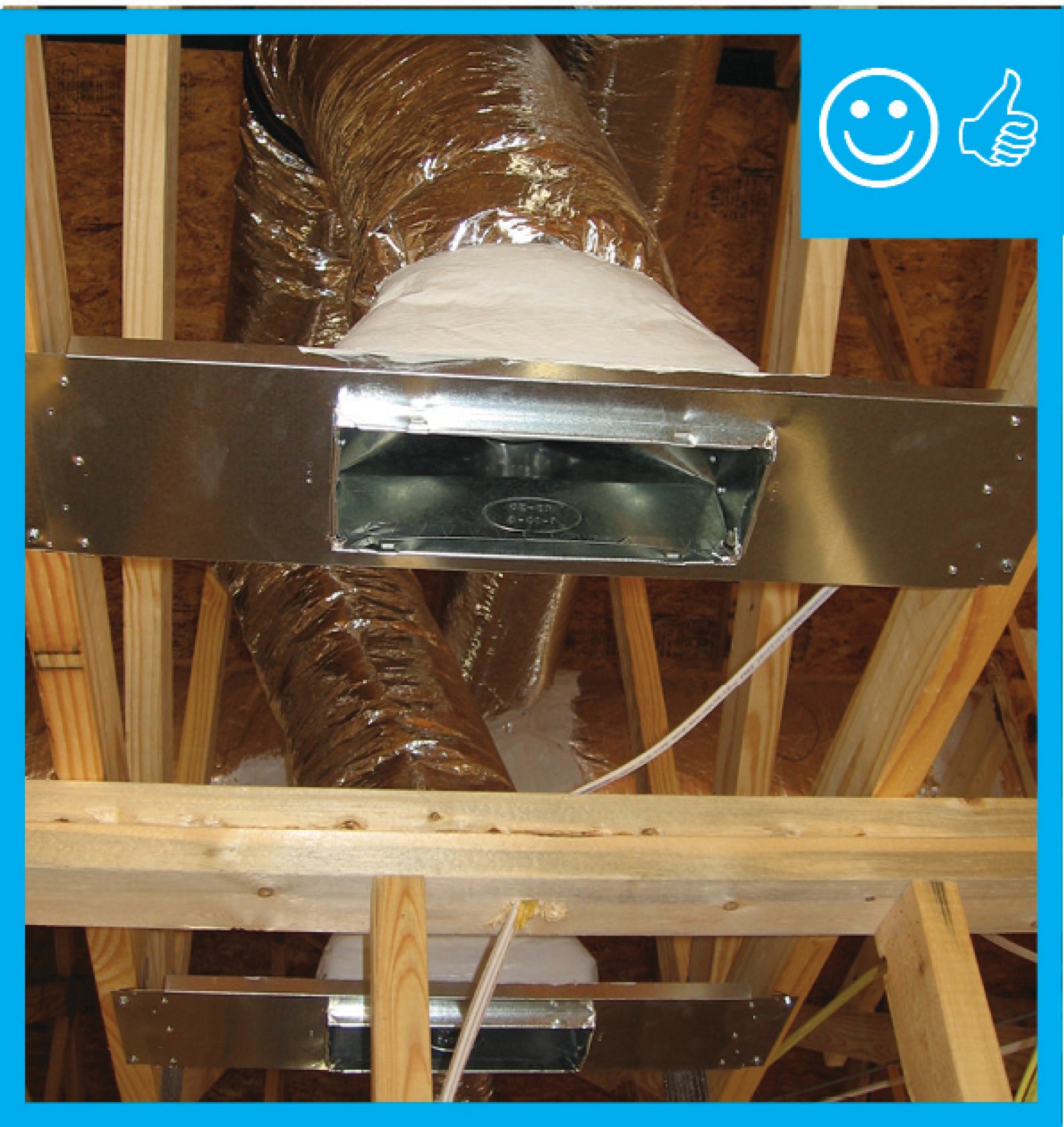
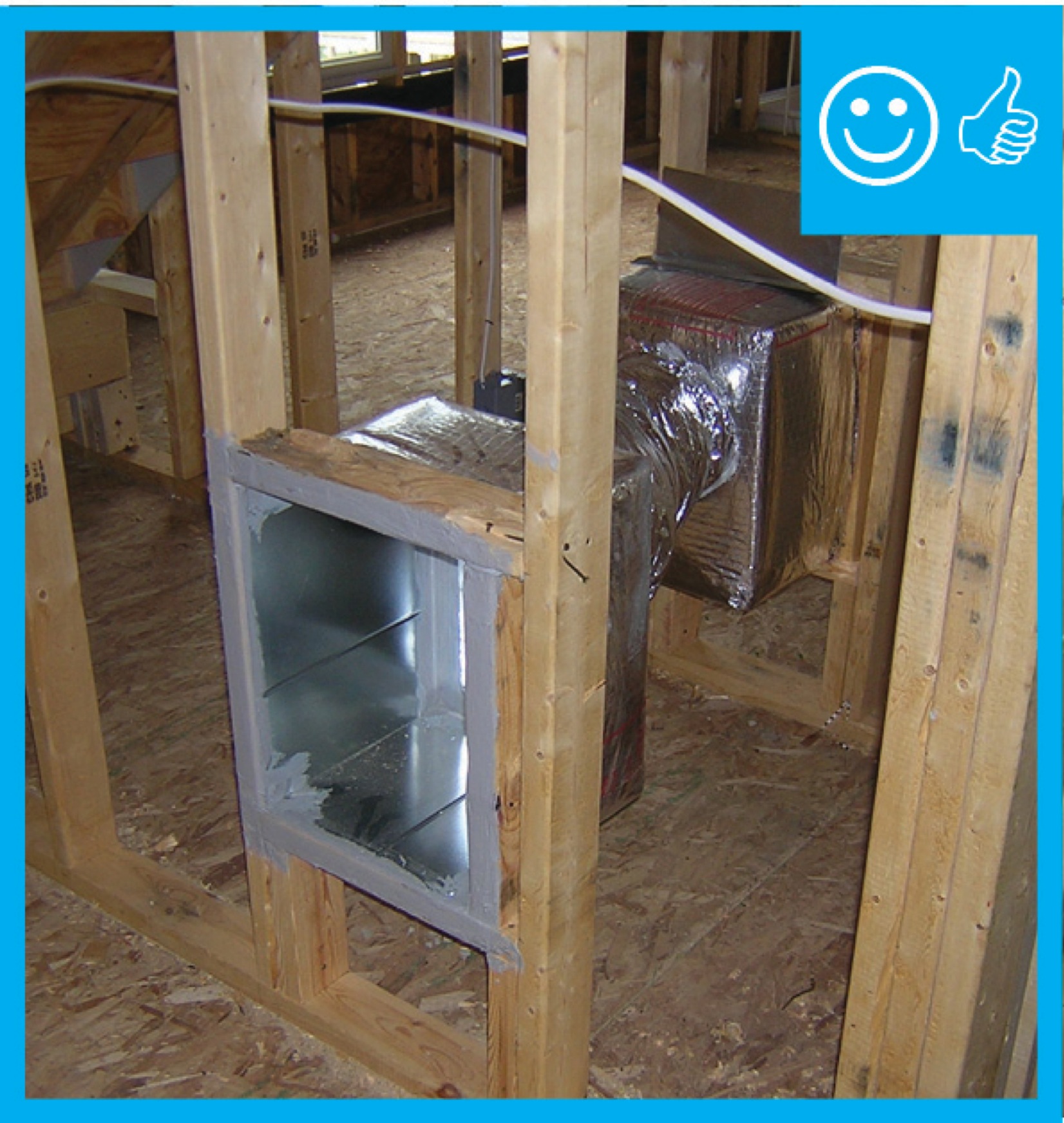
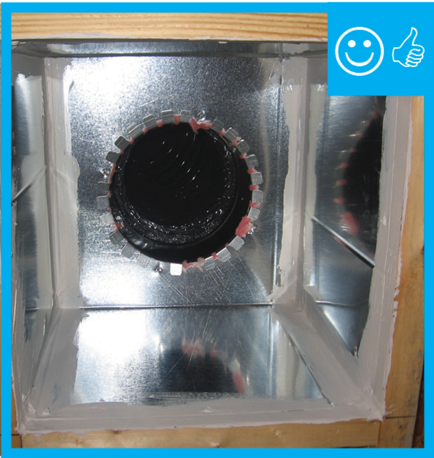
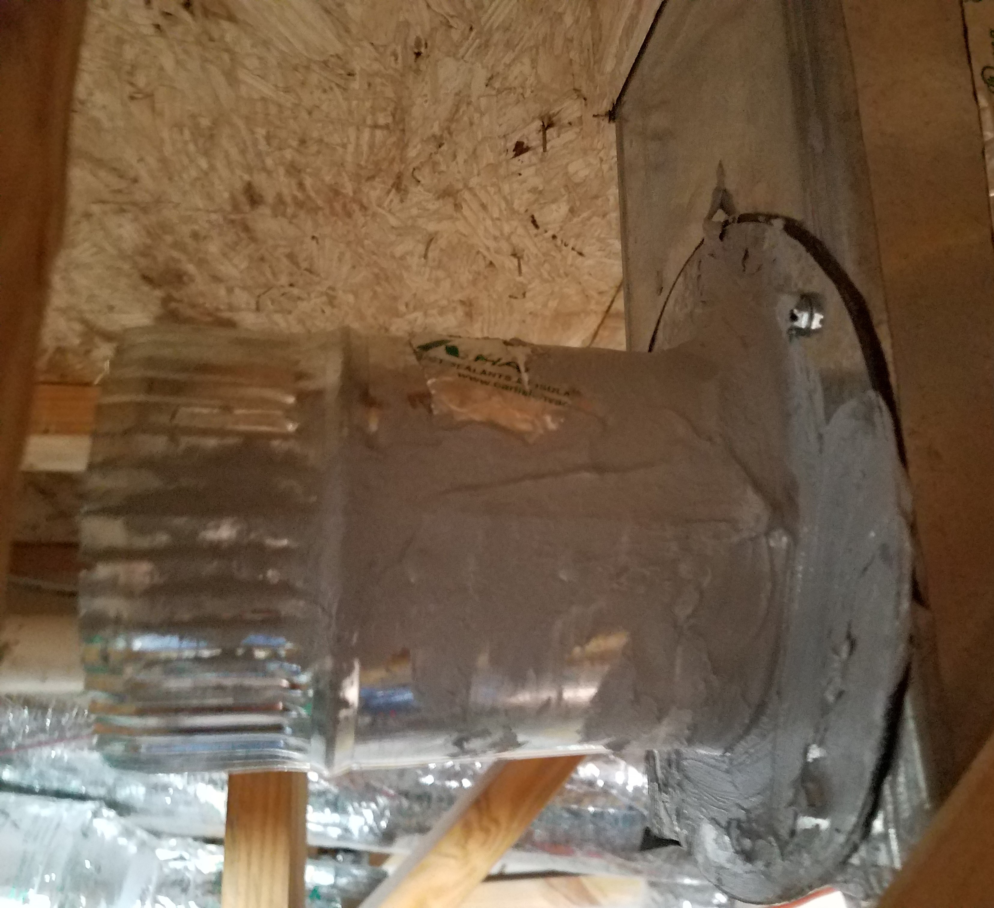
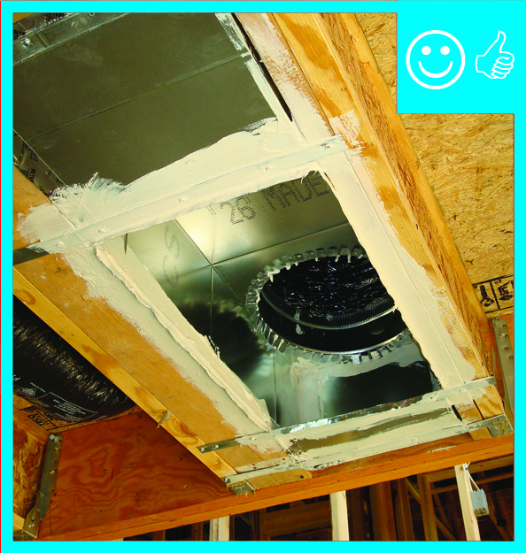
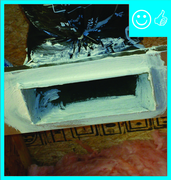
Right – Metal or fiberboard duct is mastic sealed at junction with duct register box
Image
Image
Image
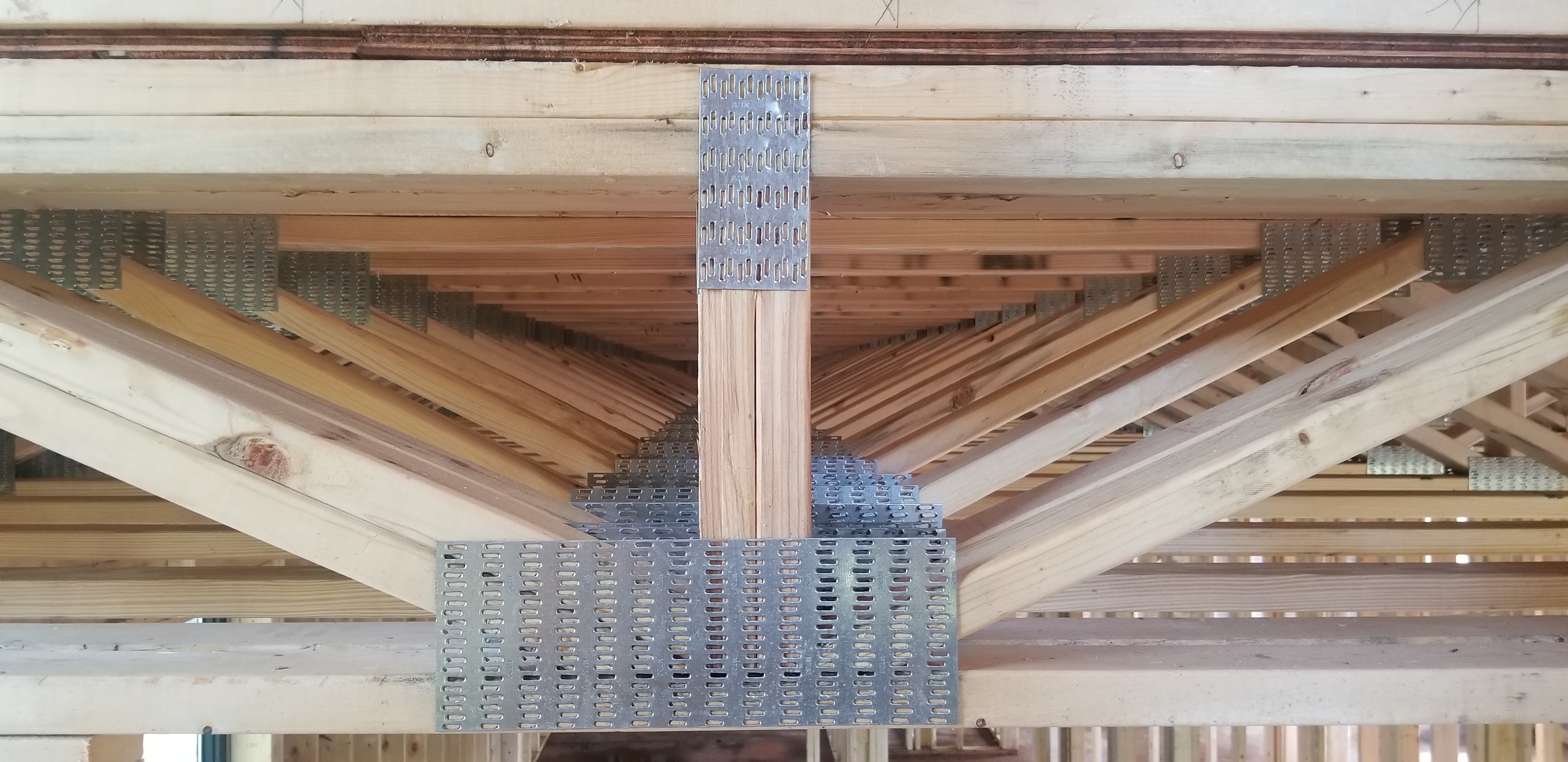
Right – Open web floor joists can provide a space between floors for HVAC ducting.
Image
Image
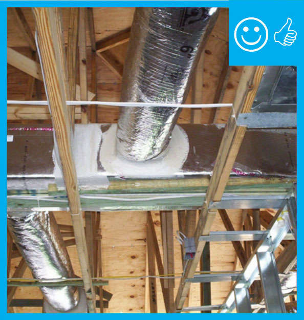
Right – Plastic tenting increases the height of the insulation above ducts that are located in the attic.
Image
Right – R-25 of open-cell spray foam lines this new home’s attic ceiling, to protect HVAC ducts from heat and cold.
Image
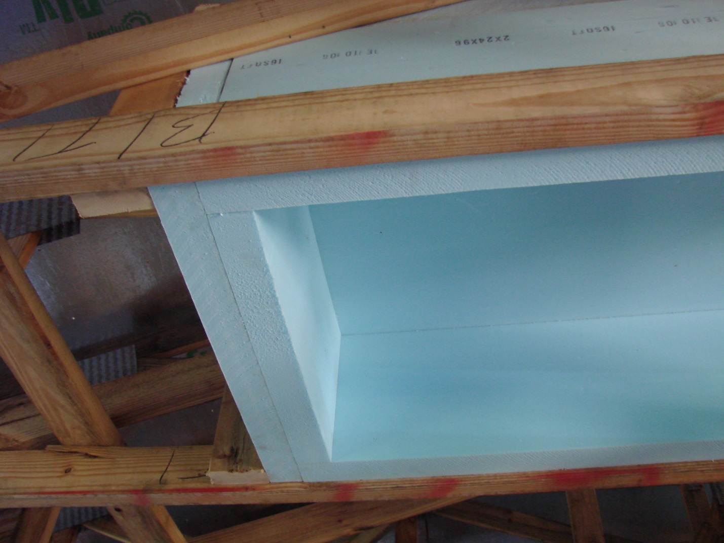
Right – Rigid foam is installed behind HVAC ducts to provide additional insulation to the ducts which are installed within the conditioned space.
Image

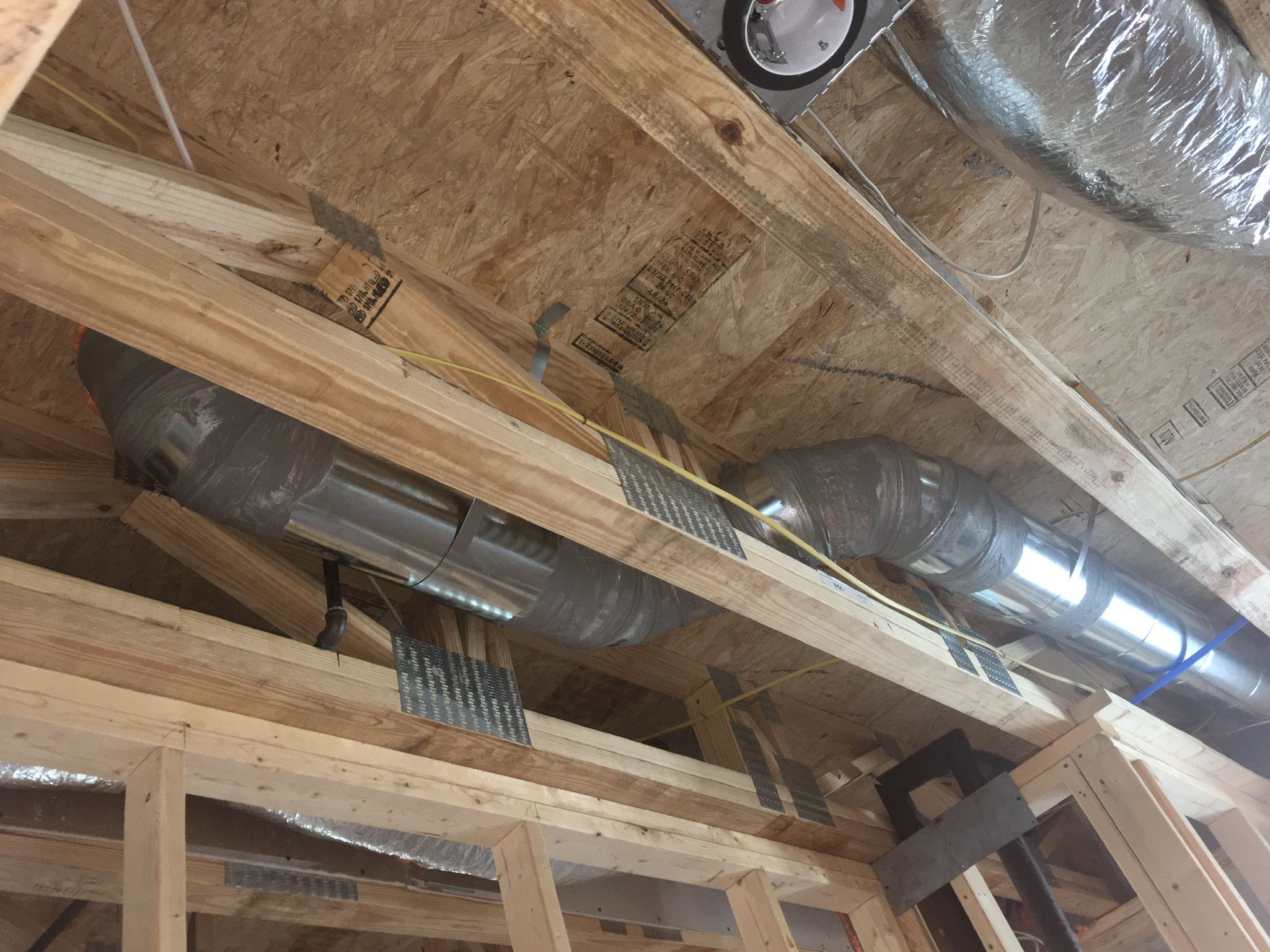
Right – The hard metal ducts are located in conditioned space between floor joists and all seams are sealed with approved metal tape.
Image
Image

Right – The termination of this kitchen exhaust duct is sealed to the wall to keep out air and water and is screened to keep out pests.
Image

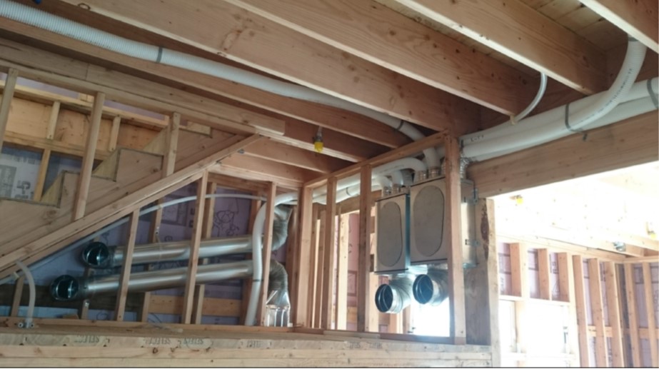
Right – This home uses a small-diameter high-velocity duct system with a main duct (plenum) that is one-fourth the size of a conventional duct and branch ducts with a 2- or 2.5-inch inside diameter.
Image
Right – This HRV is ducted separately from the home’s ductless heat pumps to provide filtered fresh air to sleeping and living areas and to exhaust stale air from the bathrooms and laundry.
Image
Right – This kitchen exhaust fan duct is made of smooth round steel duct that takes the shortest, most direct route to the outdoors and joints are sealed with mastic.
Image
Right – This supply duct is thoroughly sealed at all joints with mastic to prevent air leakage and the duct is equipped with a damper to provide zoned heating and cooling along with other trunk ducts.
Image
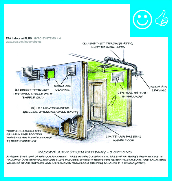
Right – Transfer grilles, Jump ducts, and wall grilles provide passive returns for air returning from bedrooms to the central HVAC system
Image
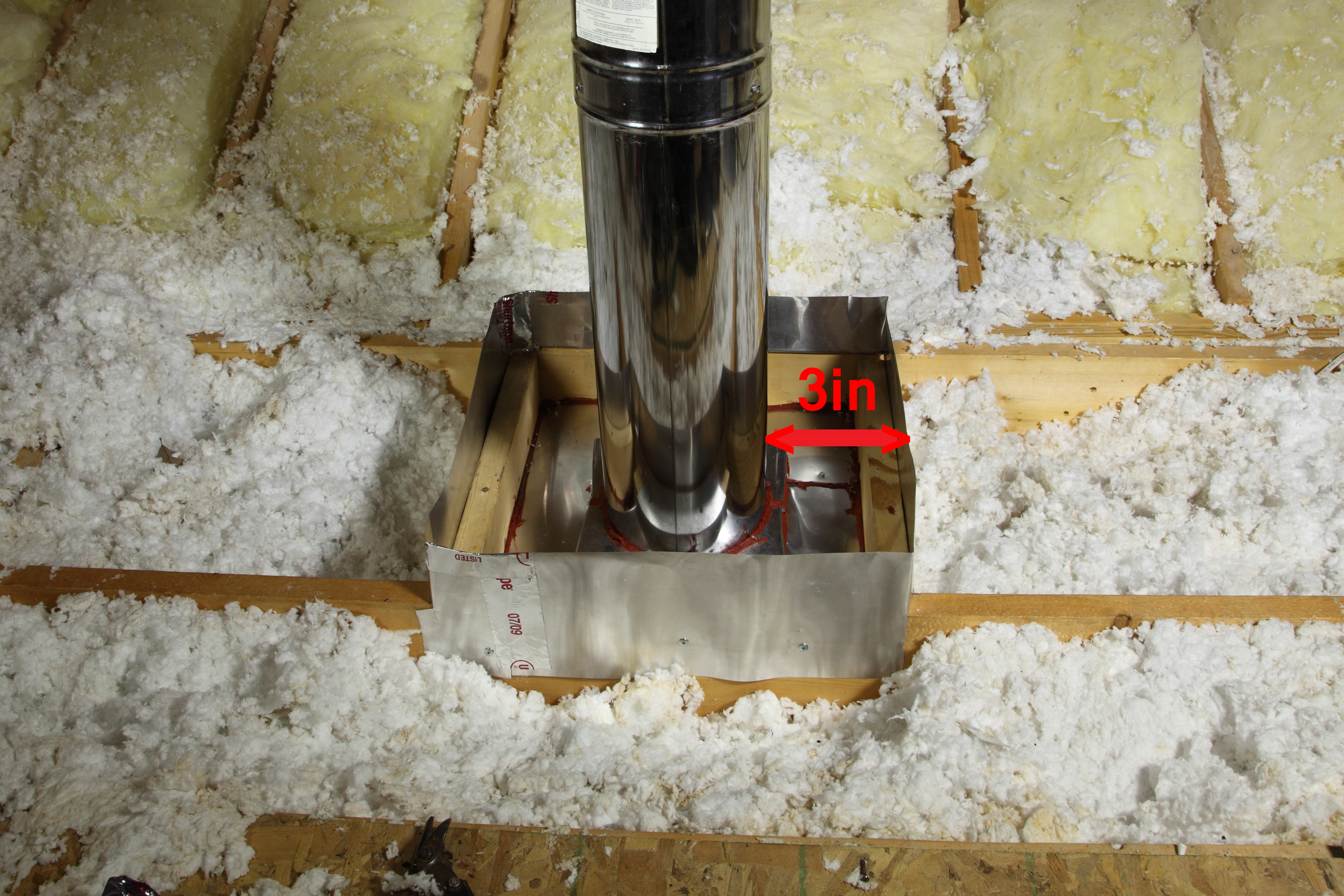
Right- This flue pipe has been air sealed with sheet metal and fire-rated caulk and an insulation dam has been constructed to keep insulation from touching the hot flue pipe
Image
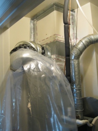
Right: A well-constructed air handler closet
Image

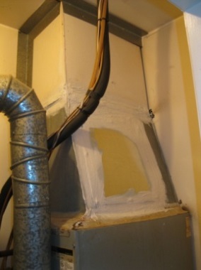
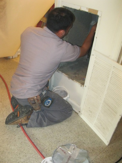
Right: Air seal all seams in the return air plenum before installing a new air handler
Image
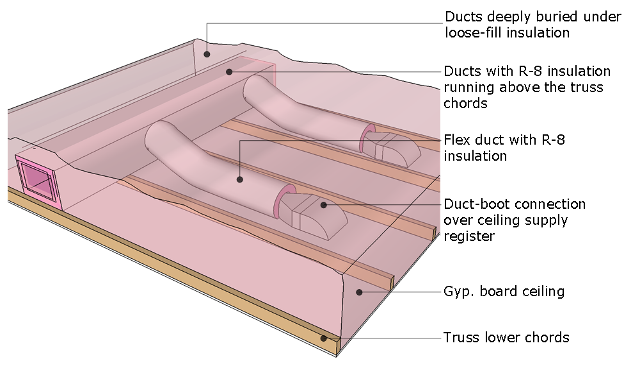
Right: Ducts are completely buried beneath insulation to the depth specified in the plans
Image
Right: ductwork is fully encapsulated with ccSPF prior to ceiling installation and burial
Image
Right: Ductwork is installed in direct contact with lower truss cords. In this picture the main trunk is laying on the truss cords and branch ducts are temporarily held with strapping across truss cords. Ducts are well sealed with mastic
Image
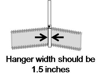
Right: If existing straps are narrower than 1.5 inches, add sheet metal saddles to keep the duct from sagging and pinching
Image
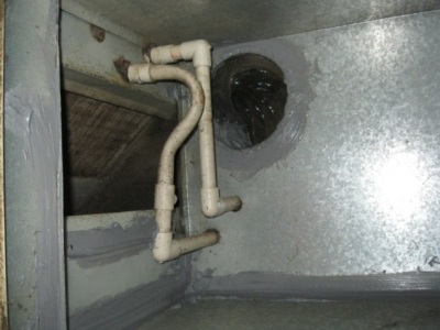
Right: Refrigerant piping is sealed where it exits the return plenum
Image
Image
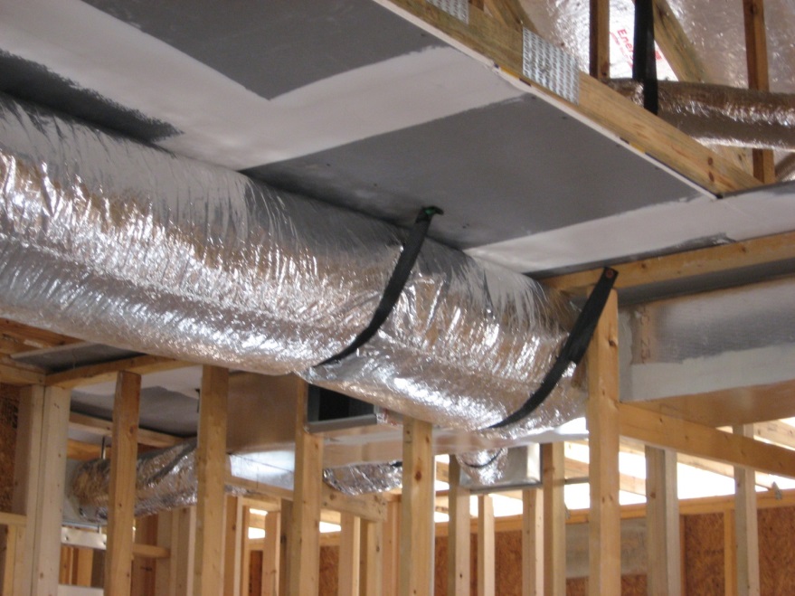
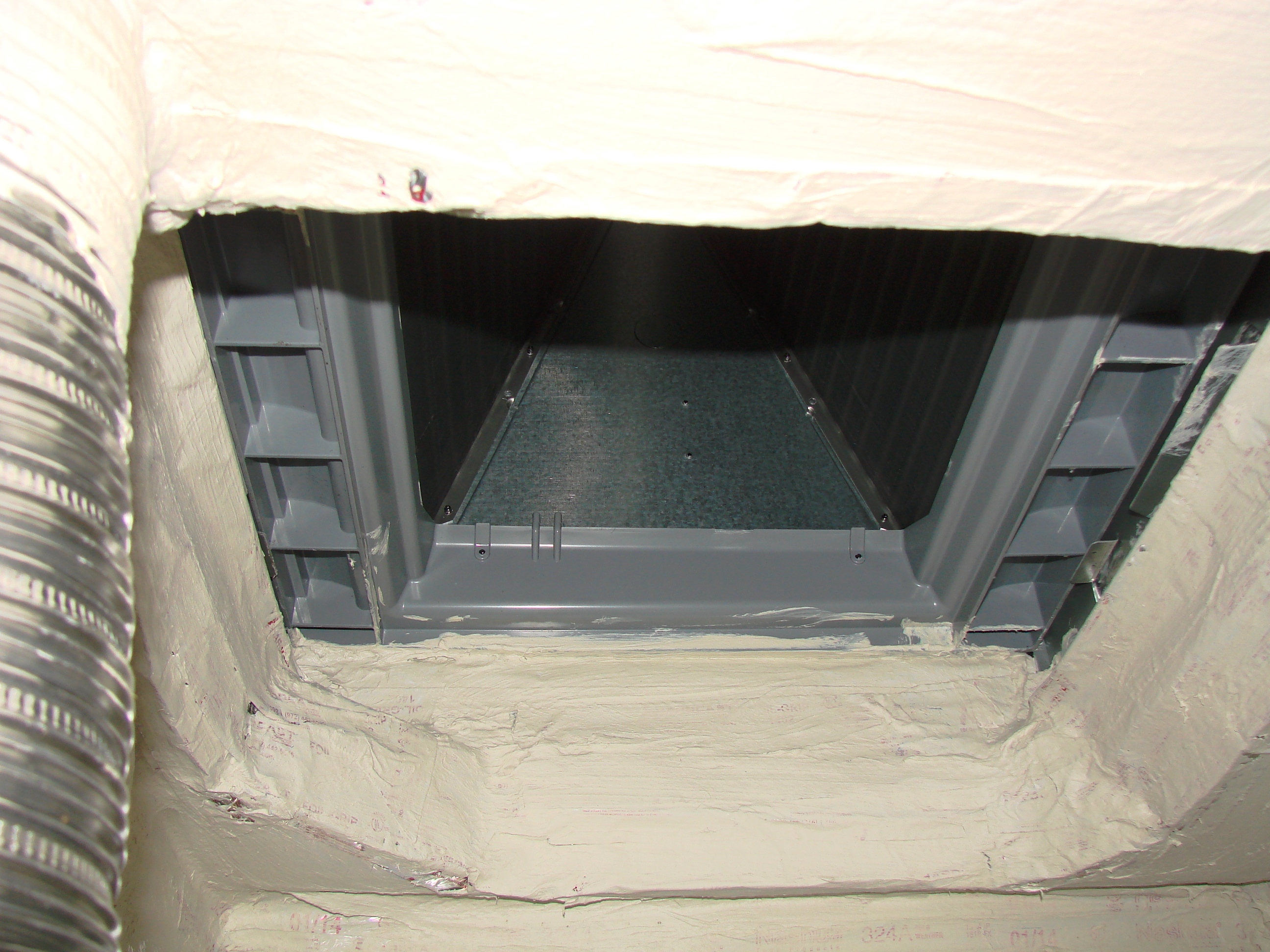
Right: Spray foam air seals and insulates raised ceiling duct chase
Image
Right: The bottom of the air handler cabinet is well sealed to the return platform