Showing results 201 - 300 of 422
Image
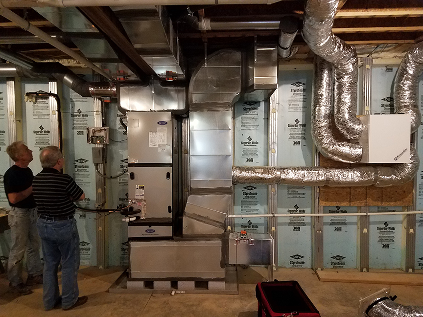
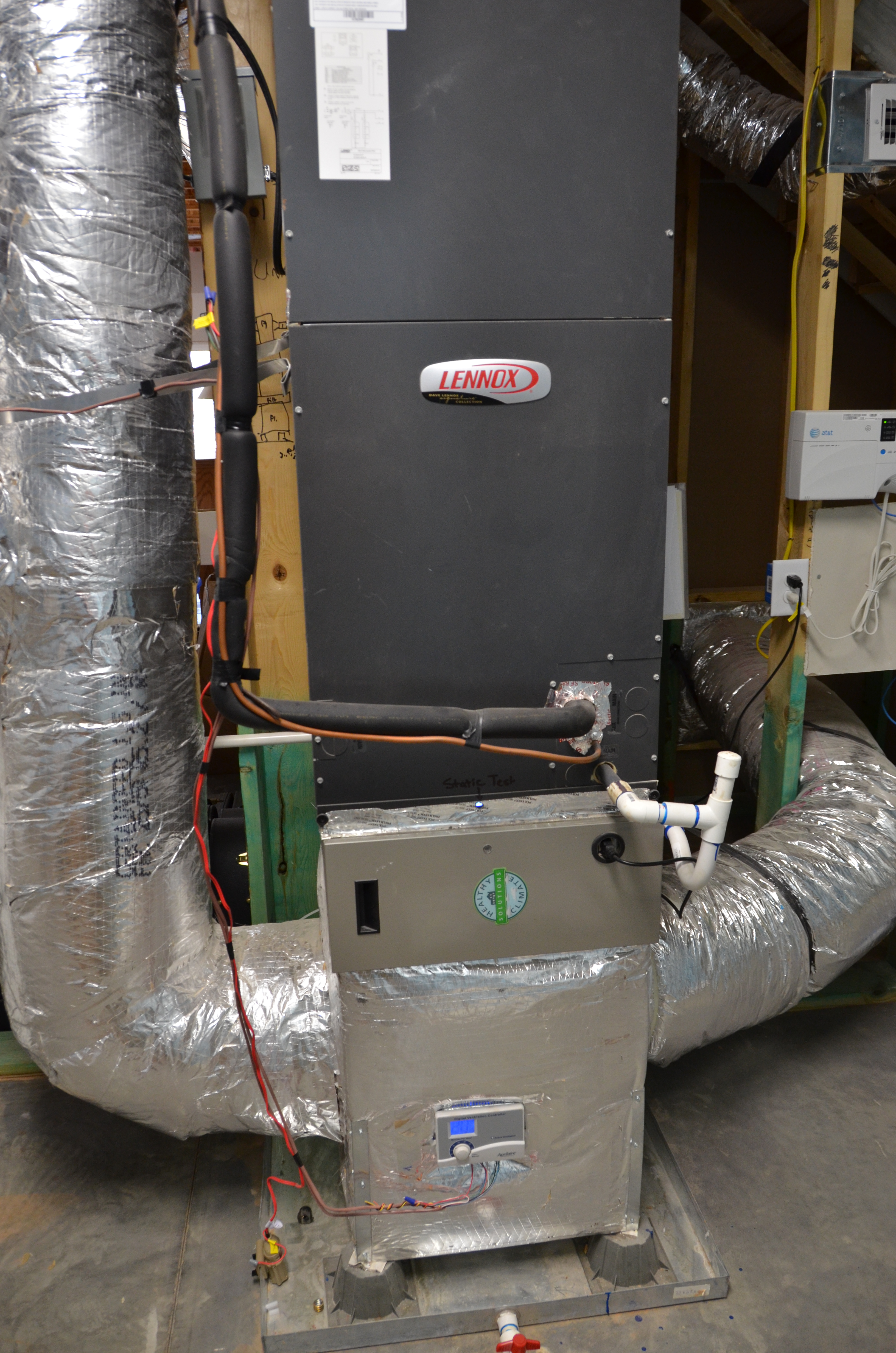
Right - The precast insulated concrete walls of the basement provide a conditioned space for the high-efficiency (18 SEER, 9.5 HSPF) air-source heat pump, with its variable-speed fan, five-stage compressor, and MERV 11 filter.
Image
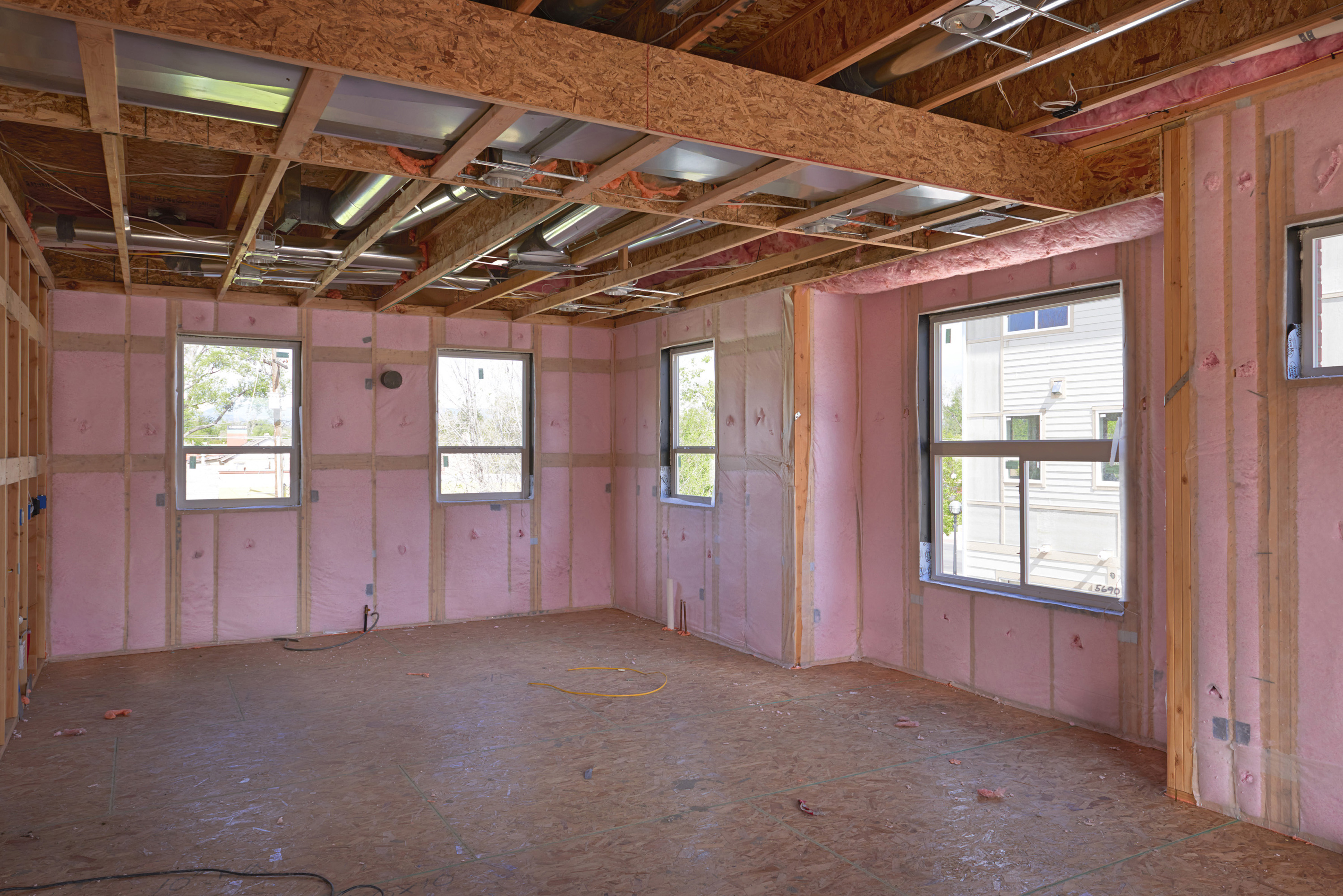
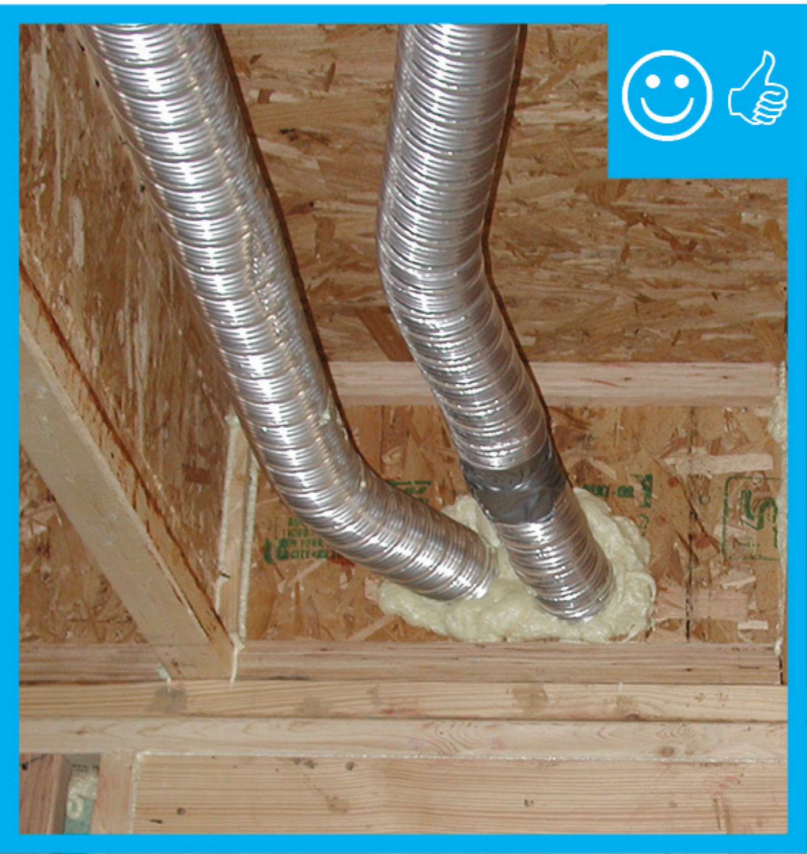
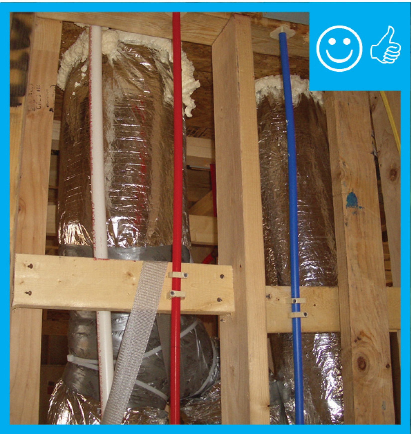
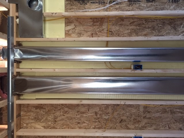
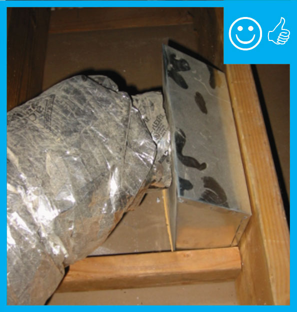
Right - The rigid metal HVAC ducting is installed between the floor joists rather than in an unconditioned attic or crawl space to minimize heat loss.
Image
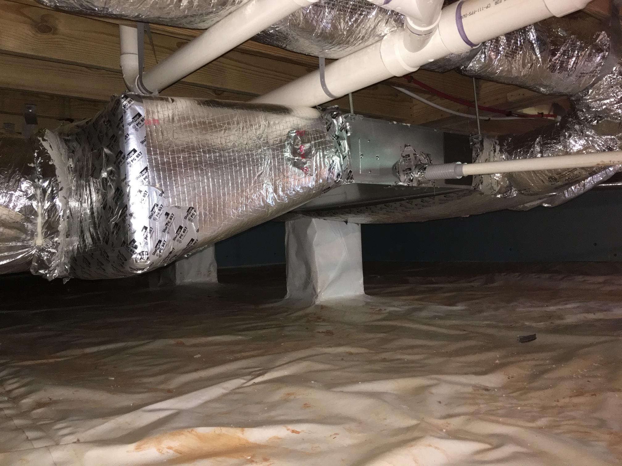
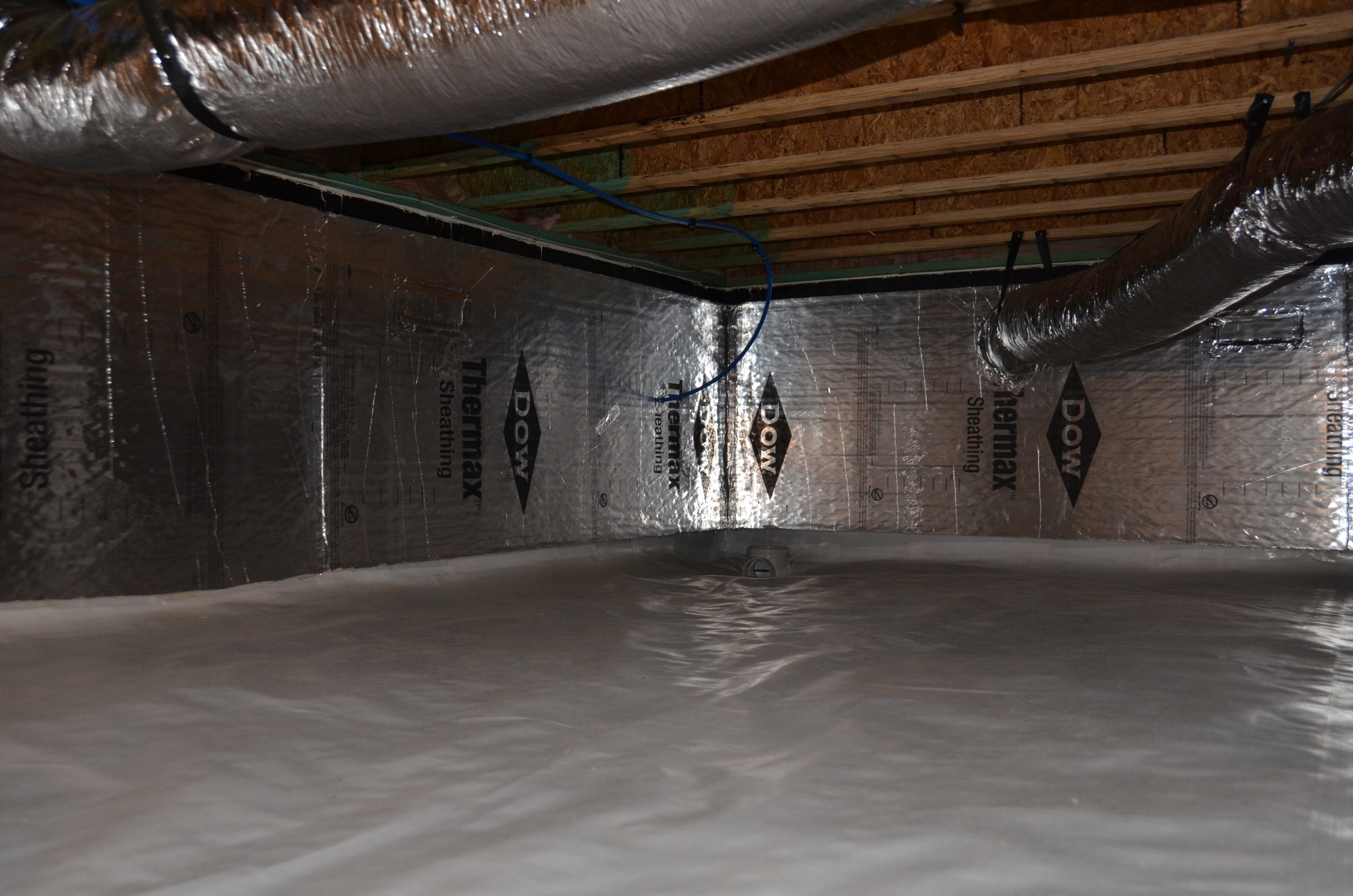
Right - the vapor barrier is extended up the sides of the piers in this crawlspace, which is sealed and insulated to house the HVAC ducts.
Image
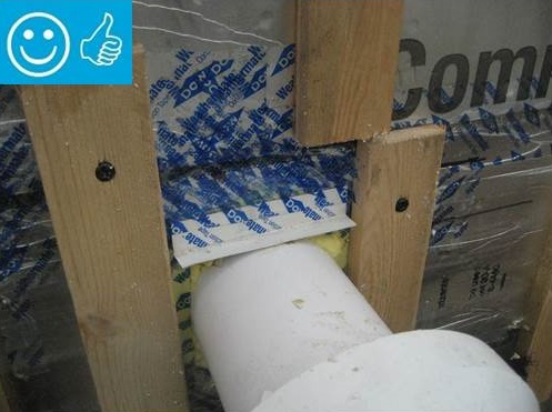
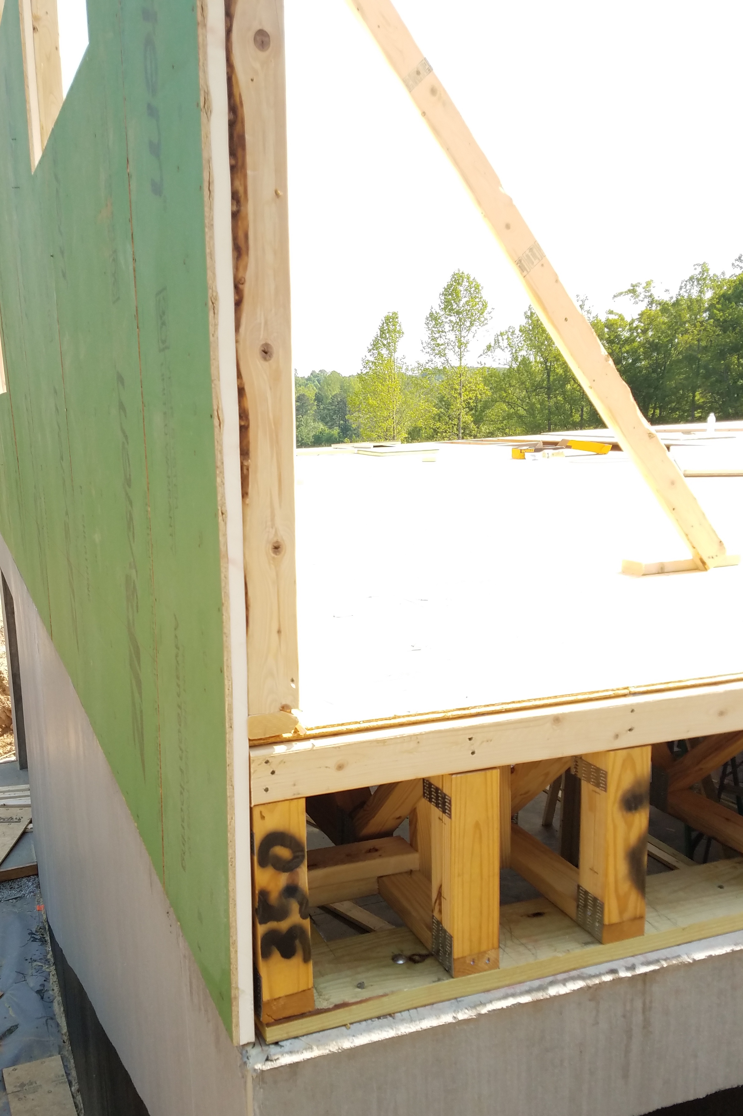
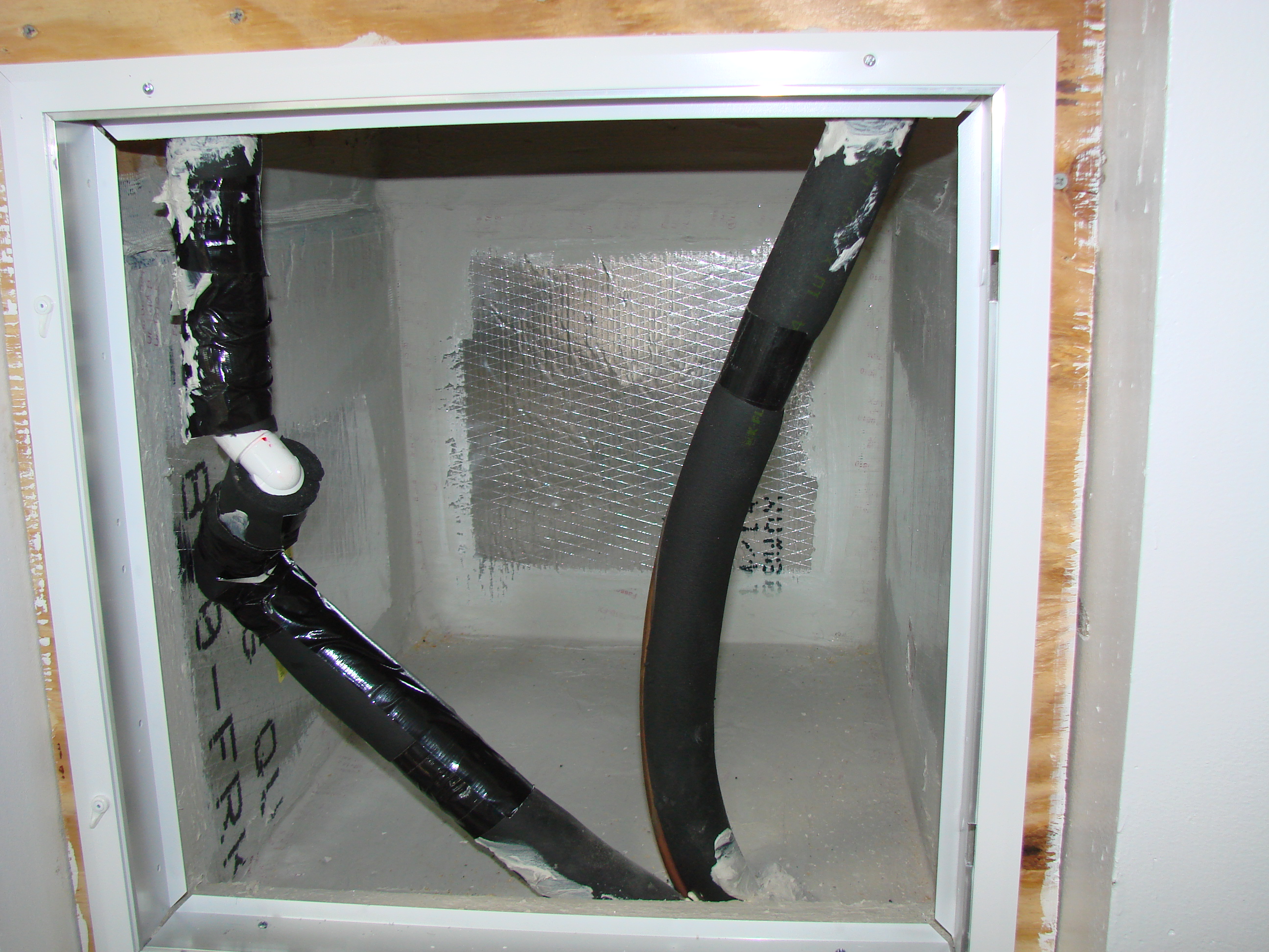
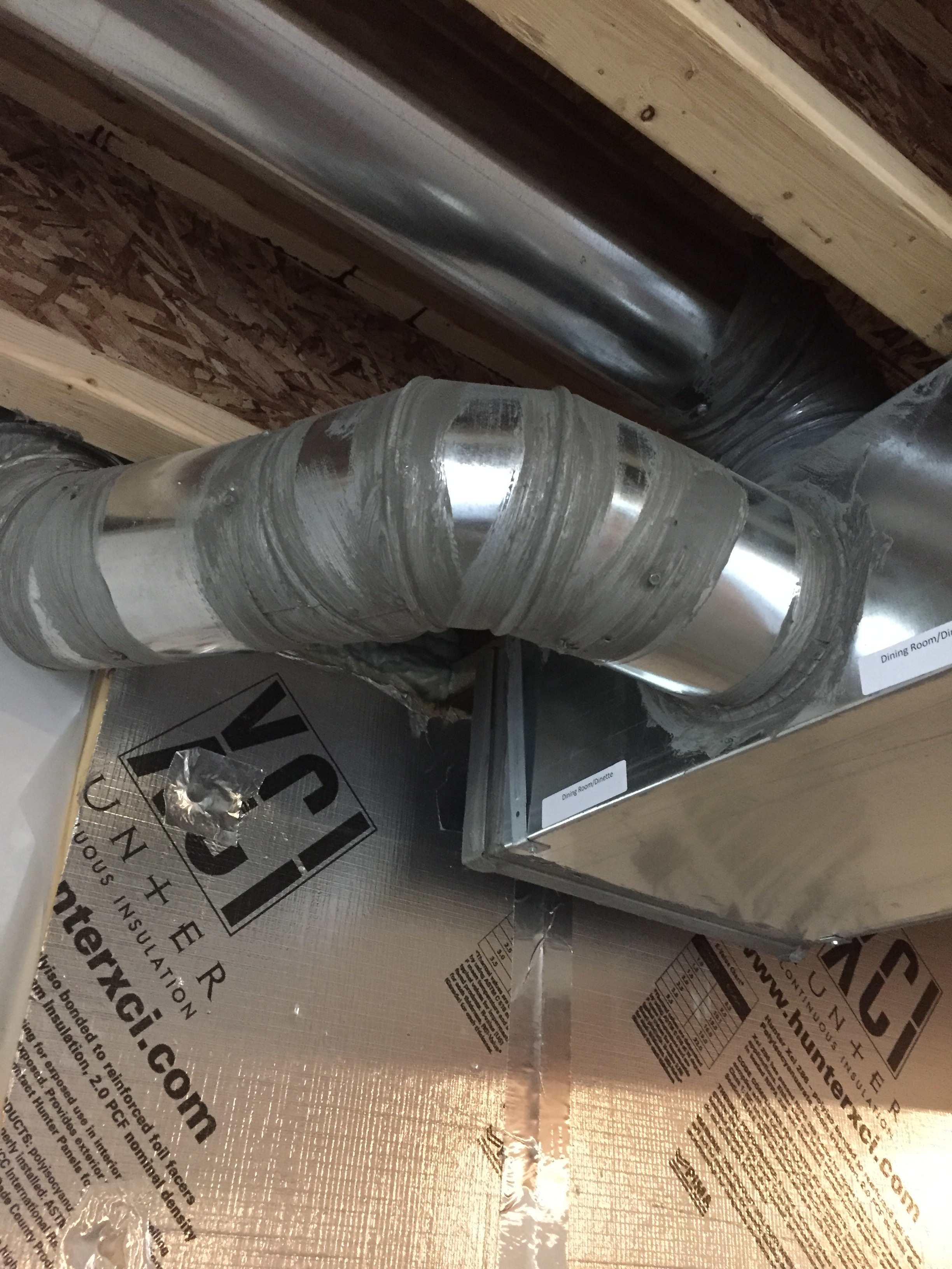
Right - This duct penetration is properly flashed and integrated with the taped, foil-faced foam sheathing layer, which serves as the air and water barrier
Image
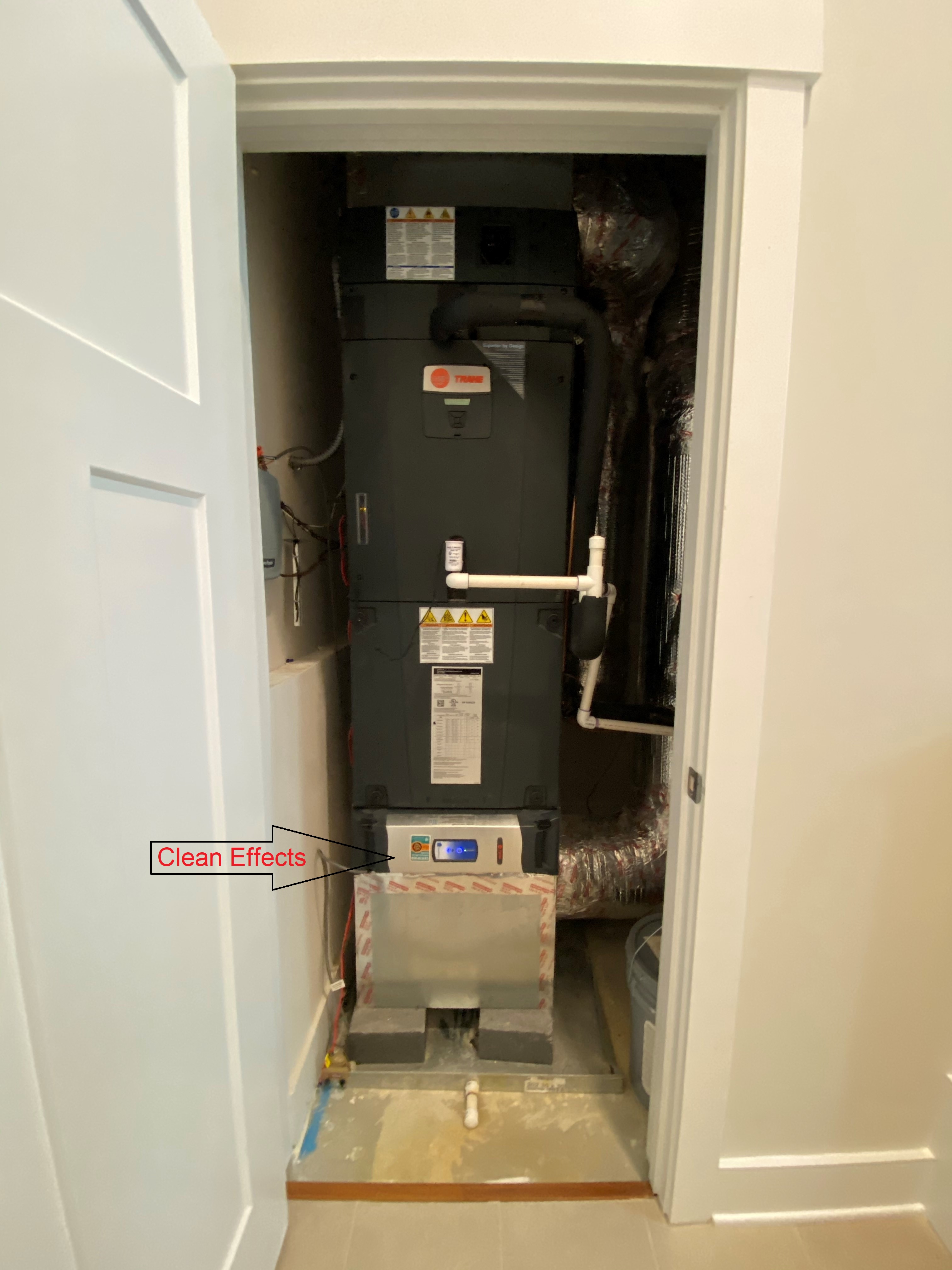
Right - This heat pump is located in a closet inside the home and all ducts are located within conditioned space between floors.
Image
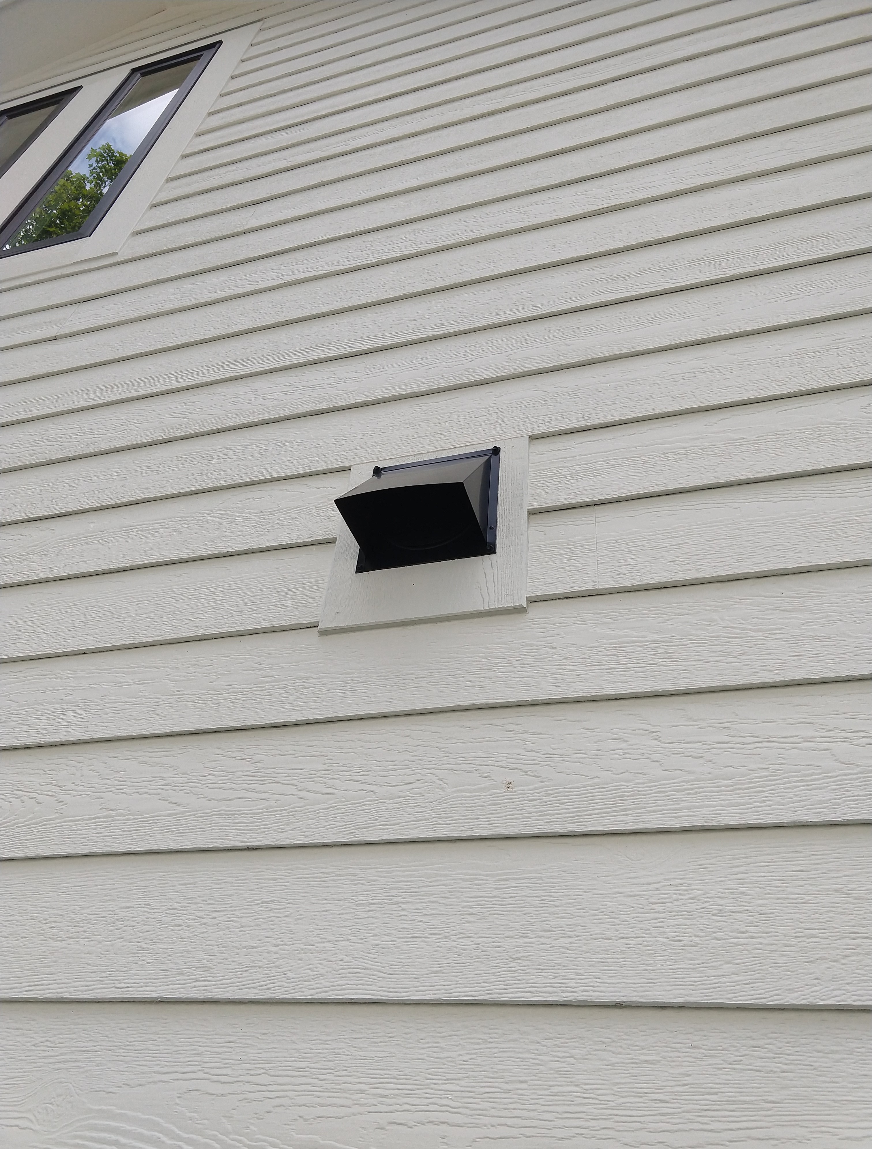
Right - This kitchen exhaust duct termination is integrated aesthetically and functionally with the exterior cladding.
Image
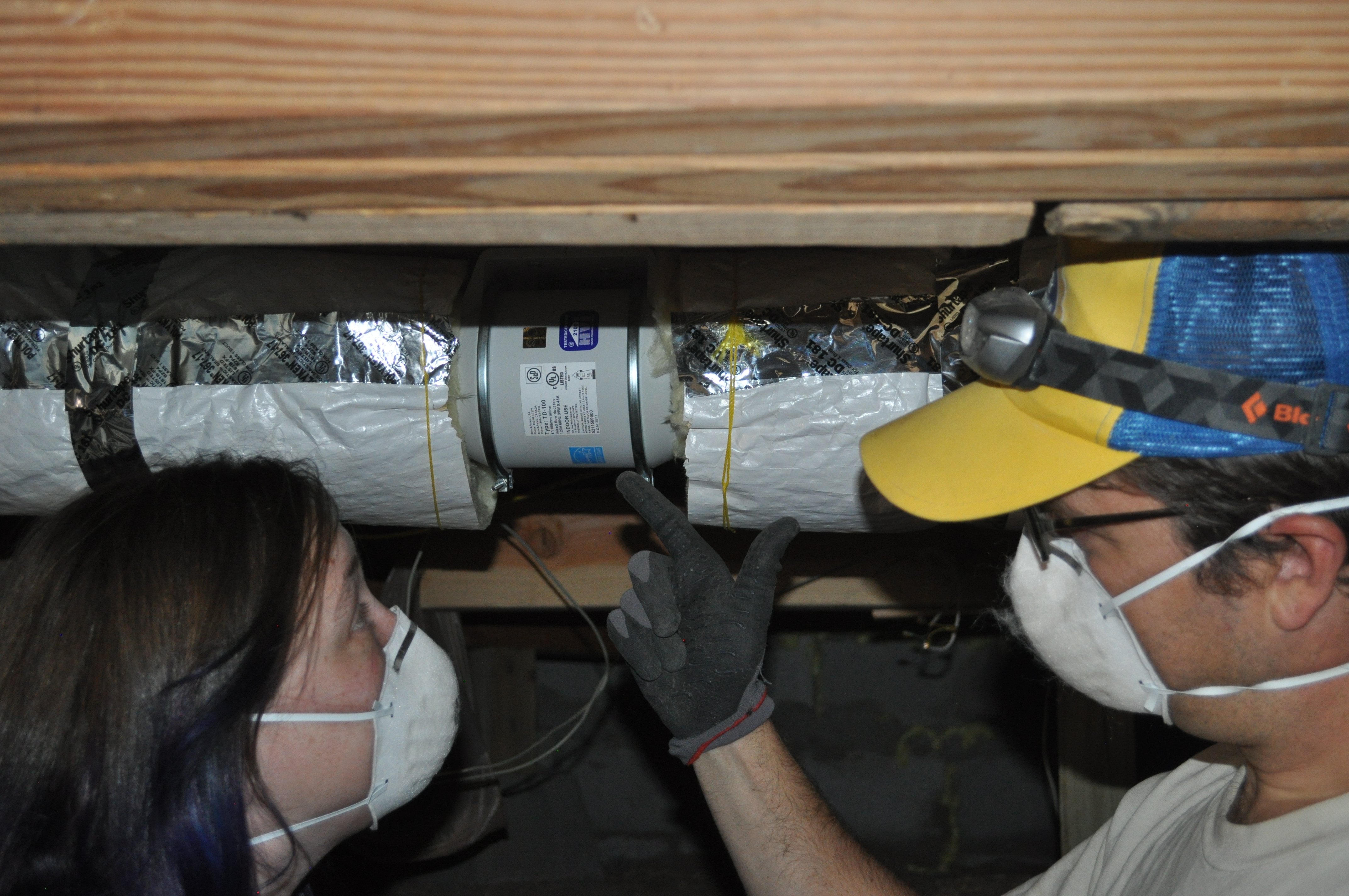
Right – a booster fan was installed in this long dryer duct to increase air flow and help prevent the duct from being clogged with lint
Image
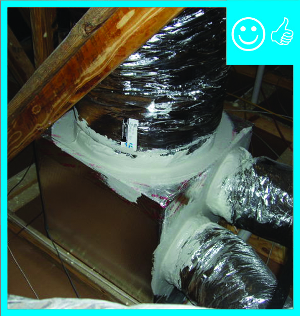
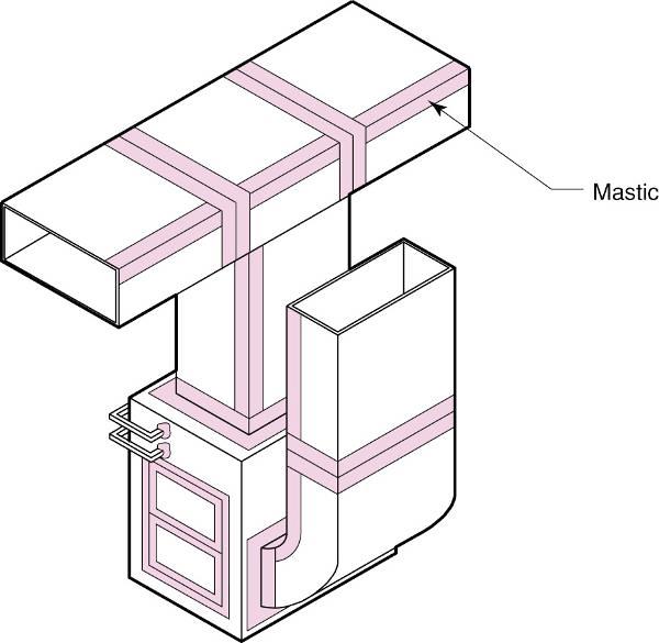
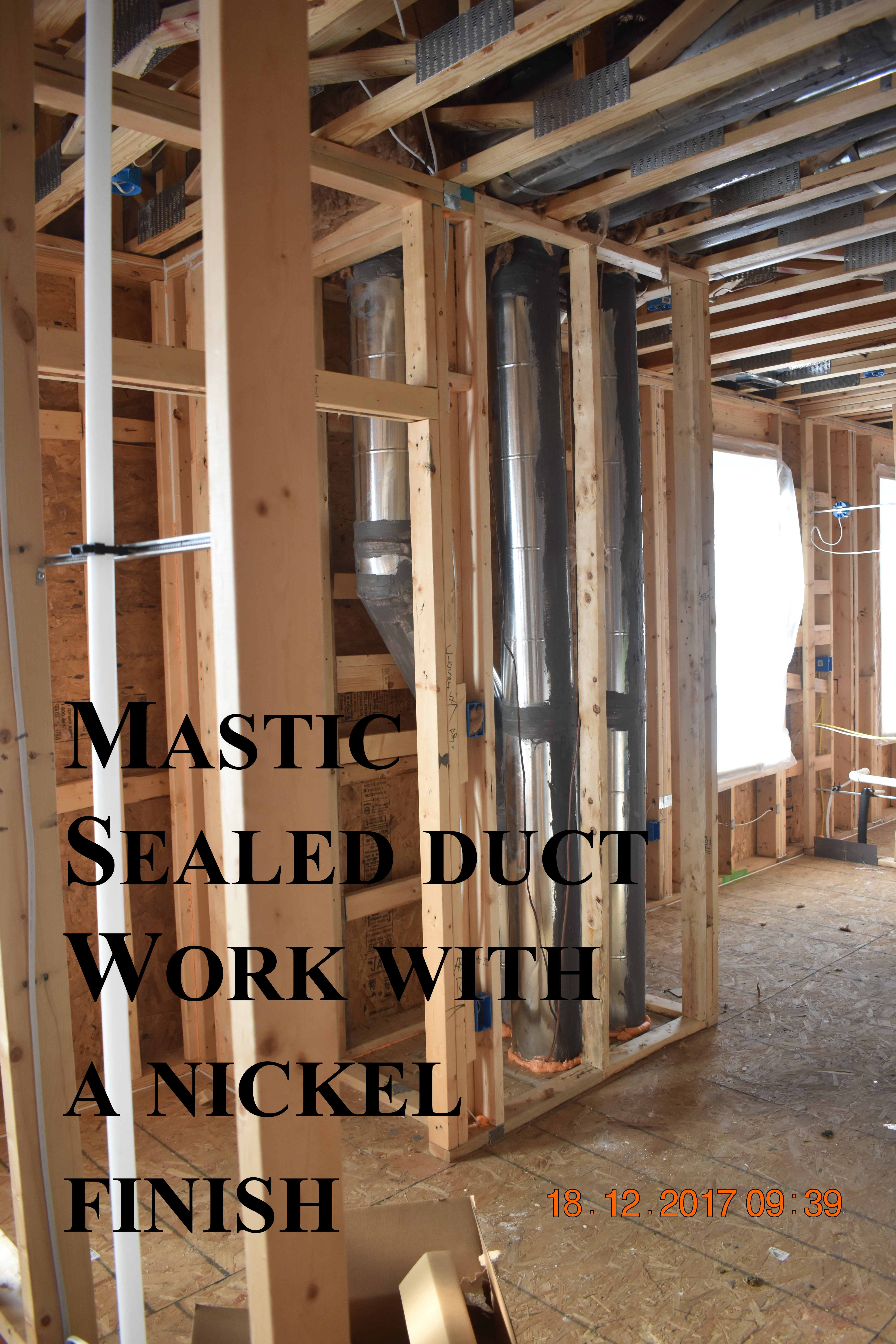
Right – A contractor installs mastic in branch duct take offs to air seal the seams where they attach to the trunk duct.
Image
Image
Right – All supply ducts in this home were located in conditioned space; any return ducts that were located in the attic were insulated with closed-cell spray foam and buried in the blown-in attic insulation to prevent air leakage and heat loss.
Image
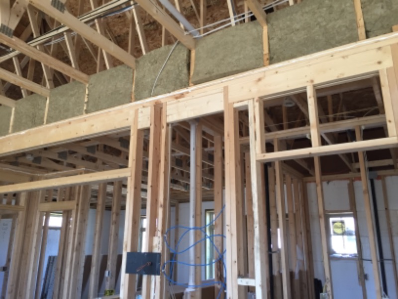
Right – Batt insulation provides additional insulation for the home’s main duct chase.
Image
Right – Chase capped with rigid air barrier and duct work penetrations properly sealed
Image
Image

Image
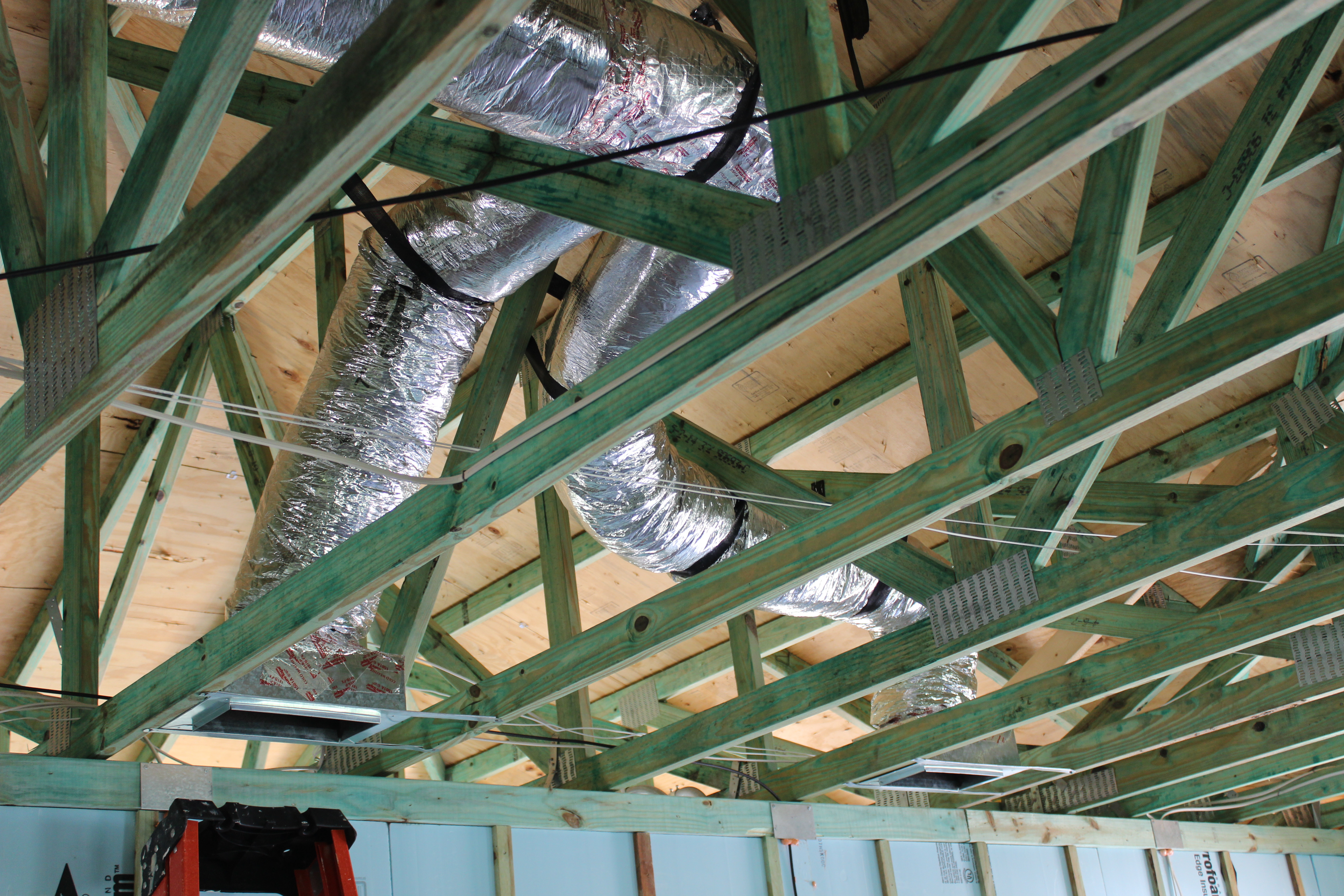
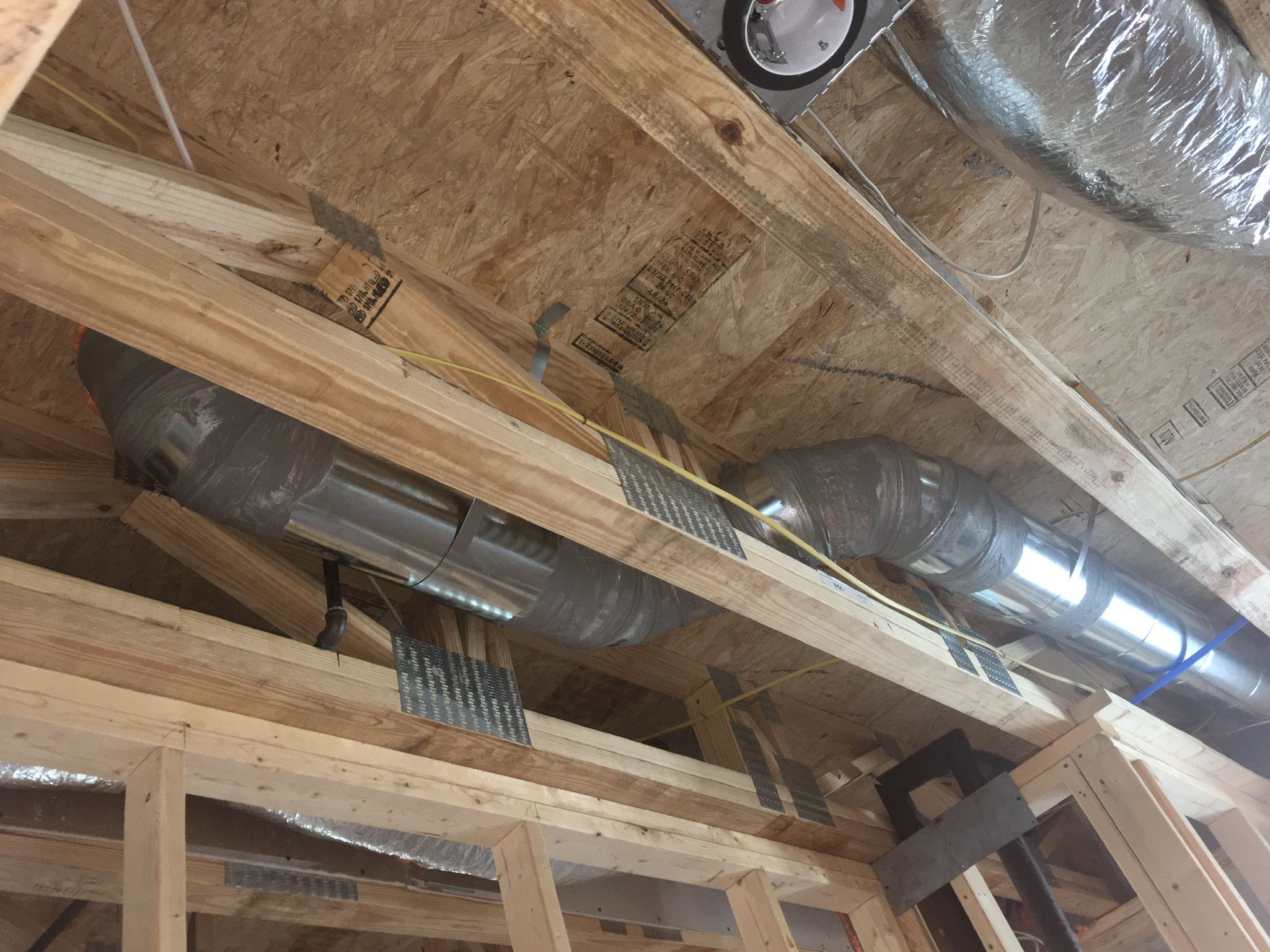
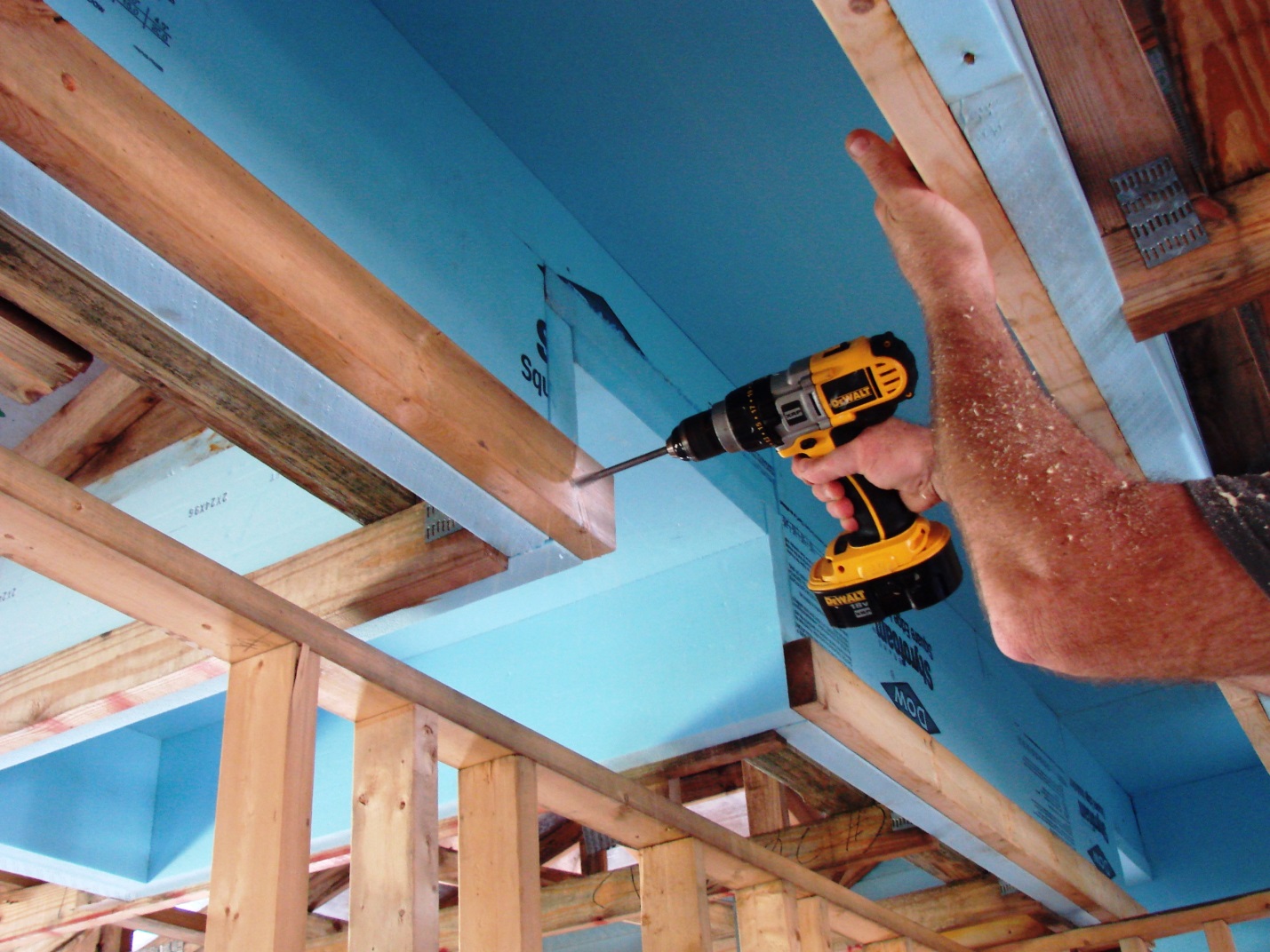
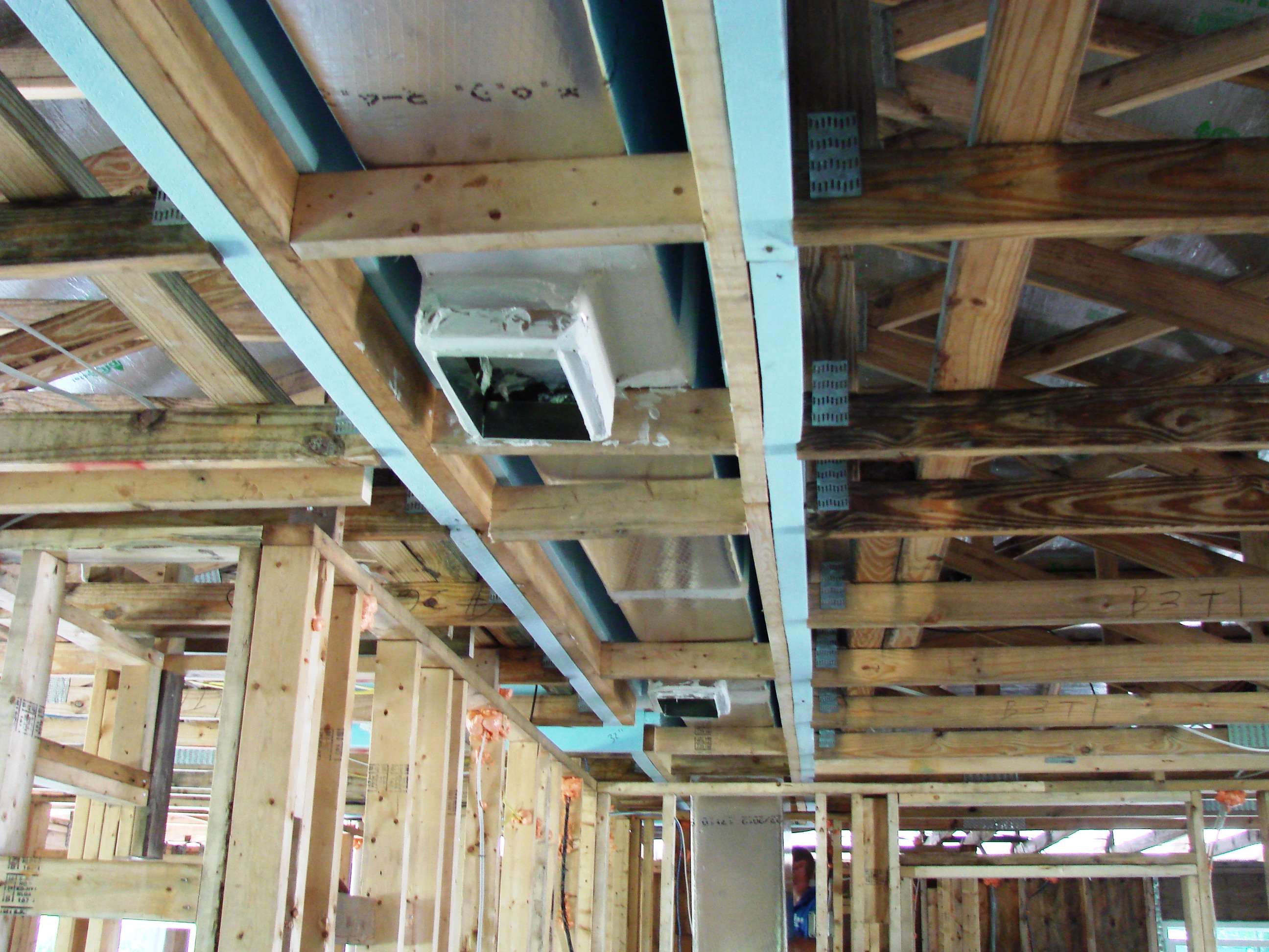
Right – Engineered open-web floor joists provide space between floors for ducting.
Image
Image
Image

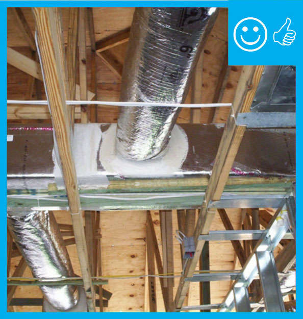
Right – Flex duct is properly connected to metal duct with a duct tie and connection is mastic sealed
Image
Image
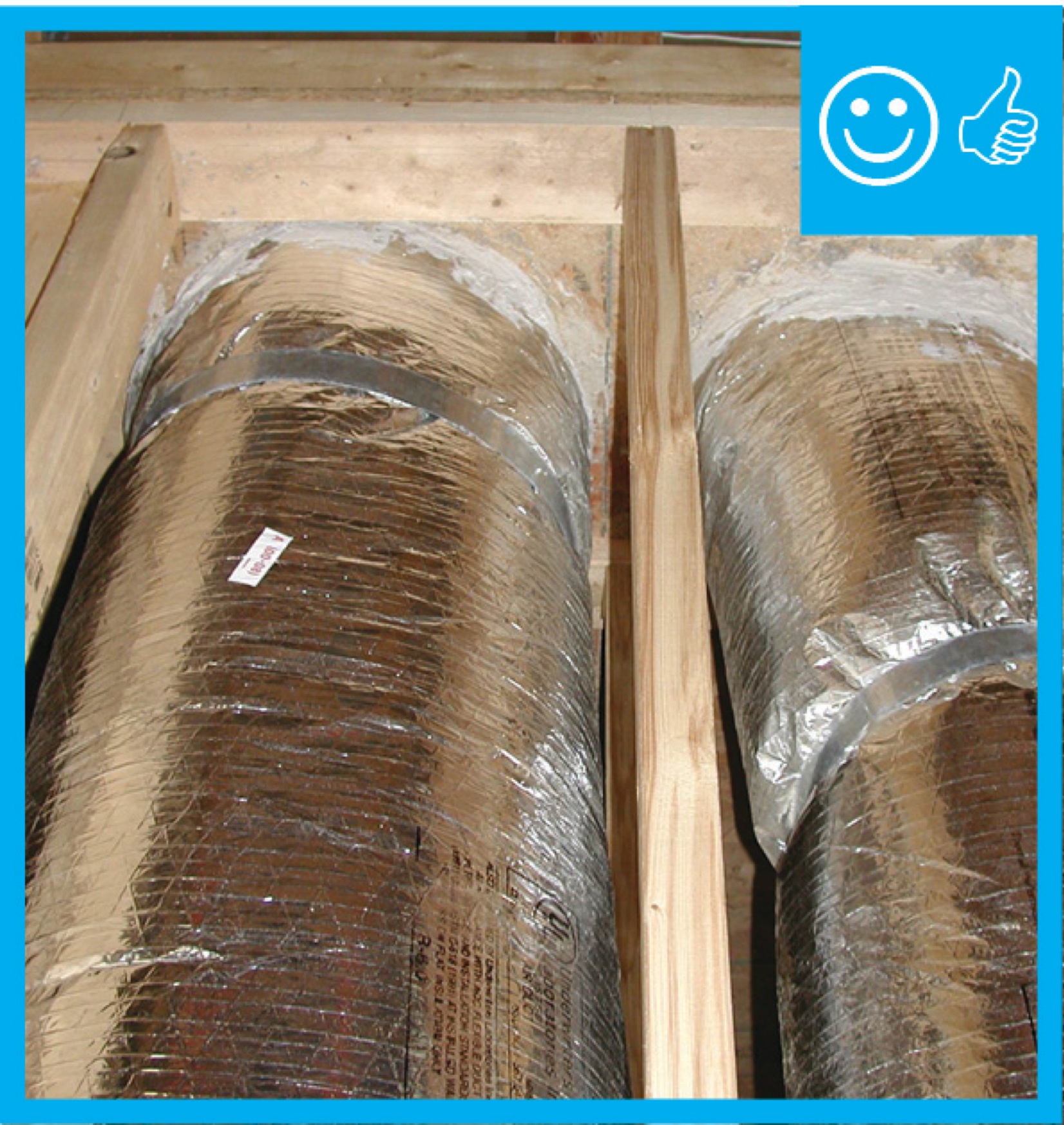
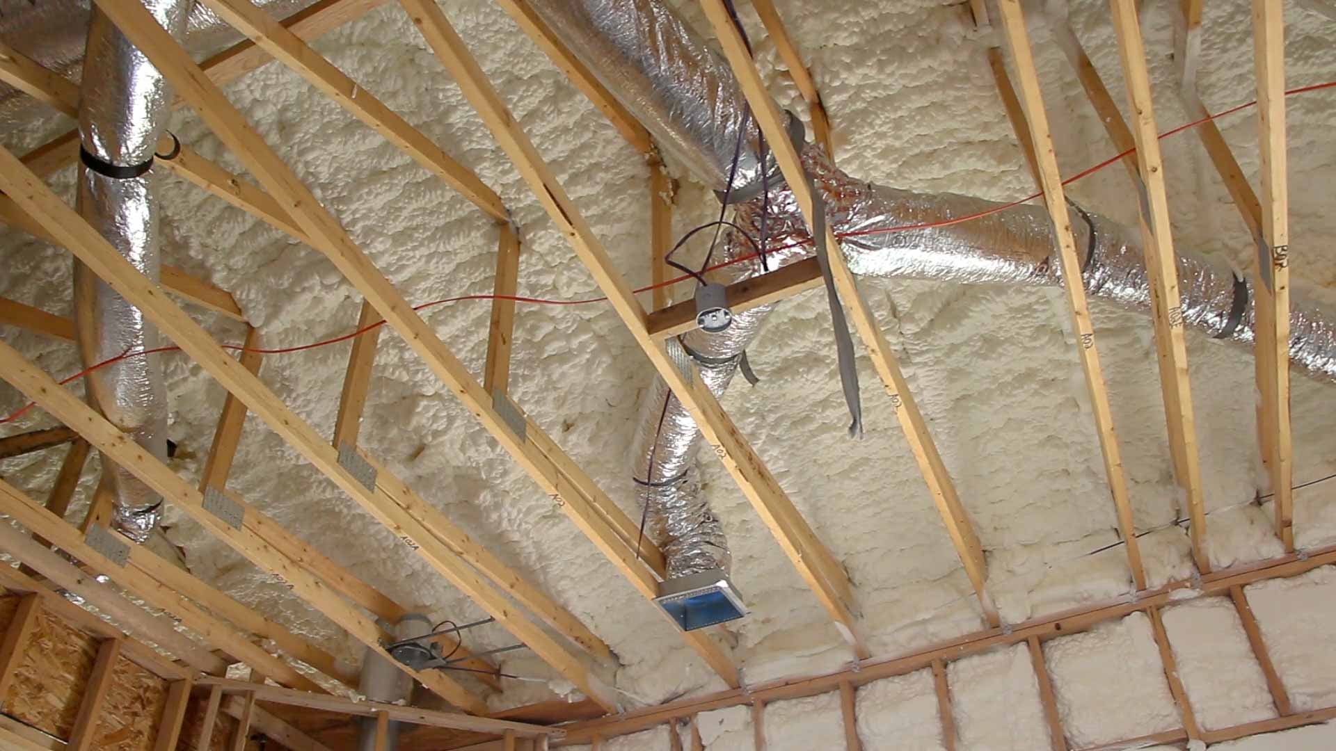
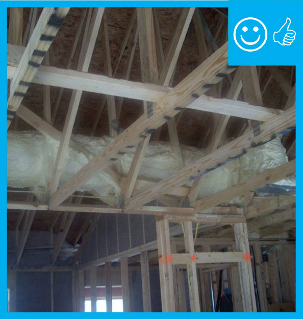
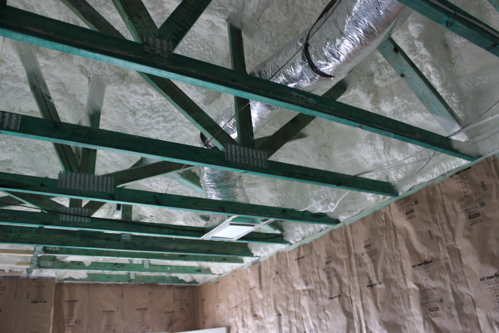
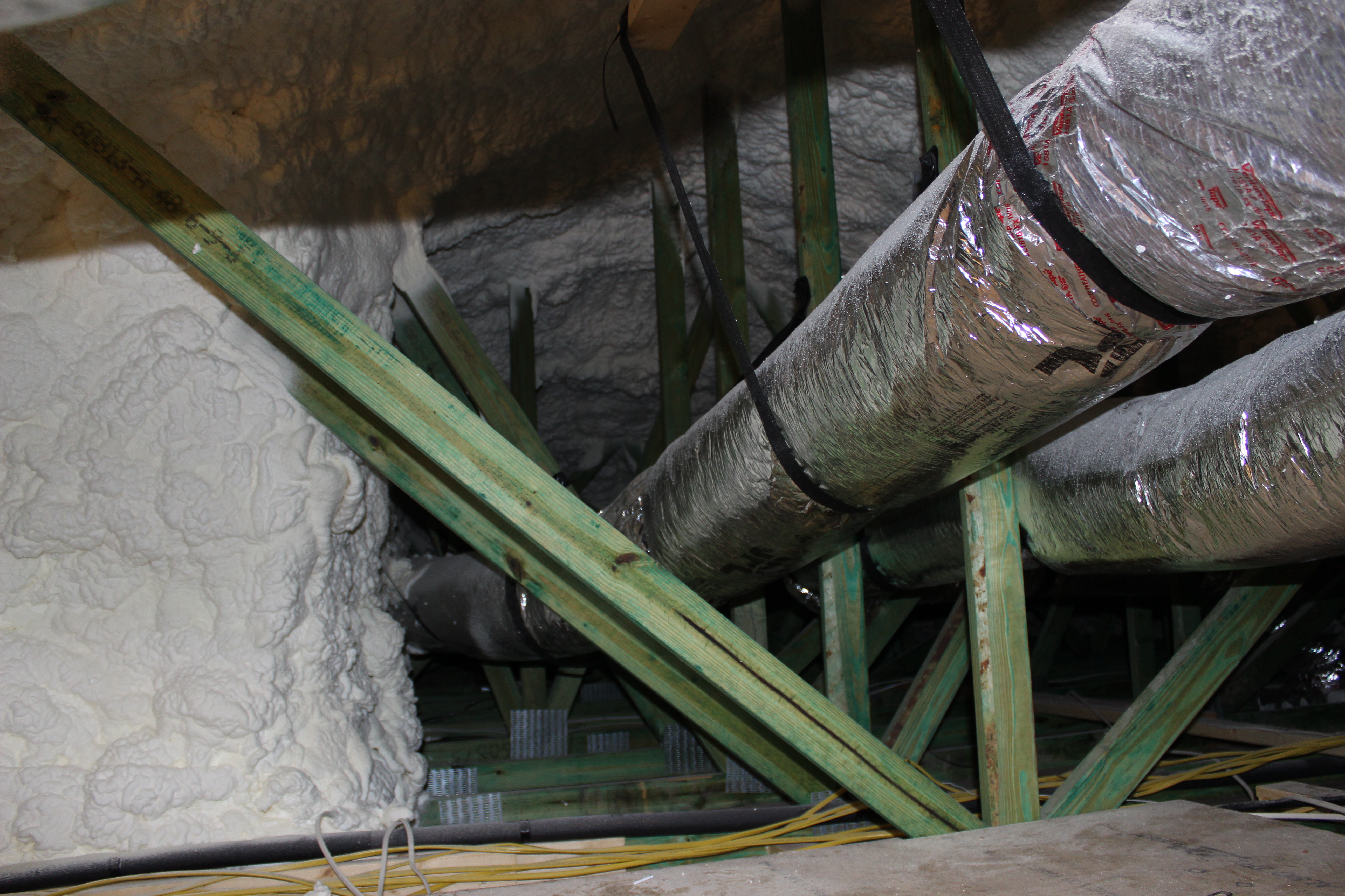
Right – Flex ducts are properly supported with straps that don’t pinch the insulation; closed-cell spray foam will be applied to the underside of the roof deck of this hot-humid climate home to provide an insulated attic space for the HVAC ducts.
Image
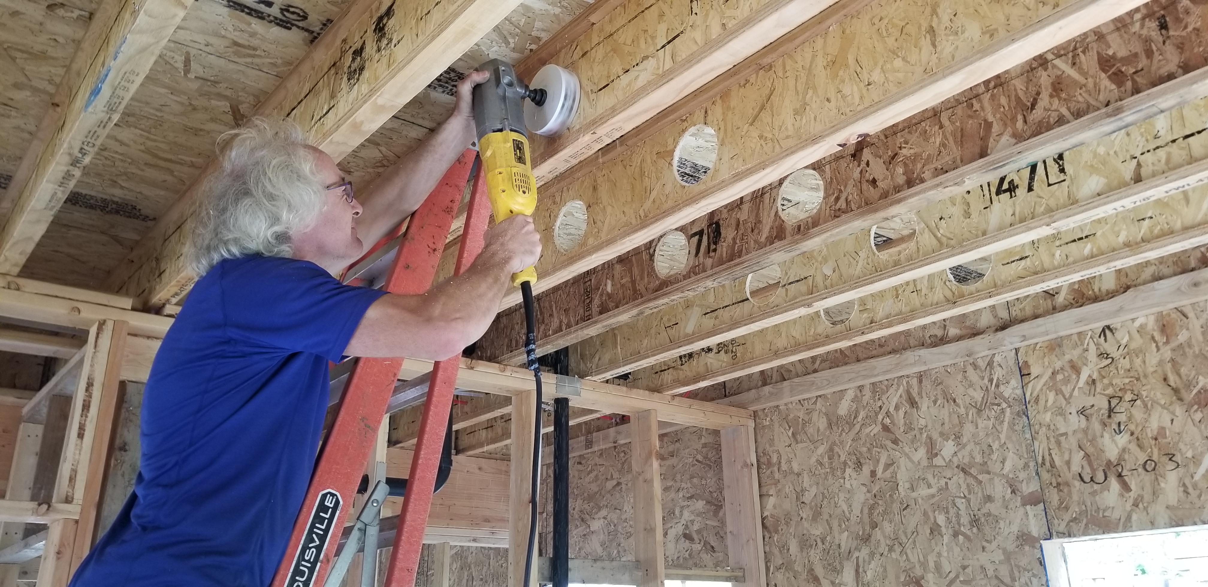
Right – Holes were drilled into the I joists between floors to run the small-diameter HRV ducts.
Image

Image
Image
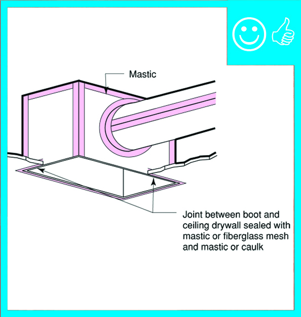
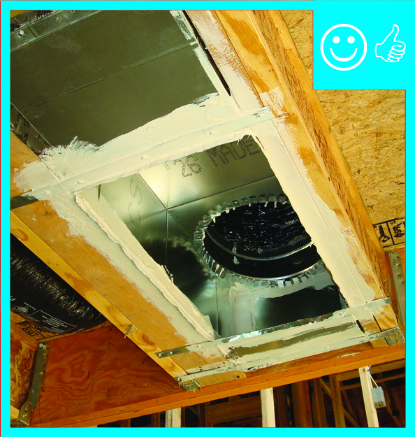
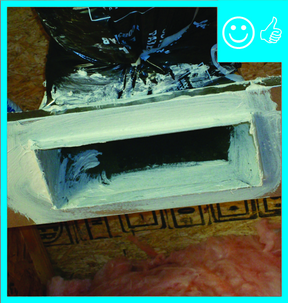
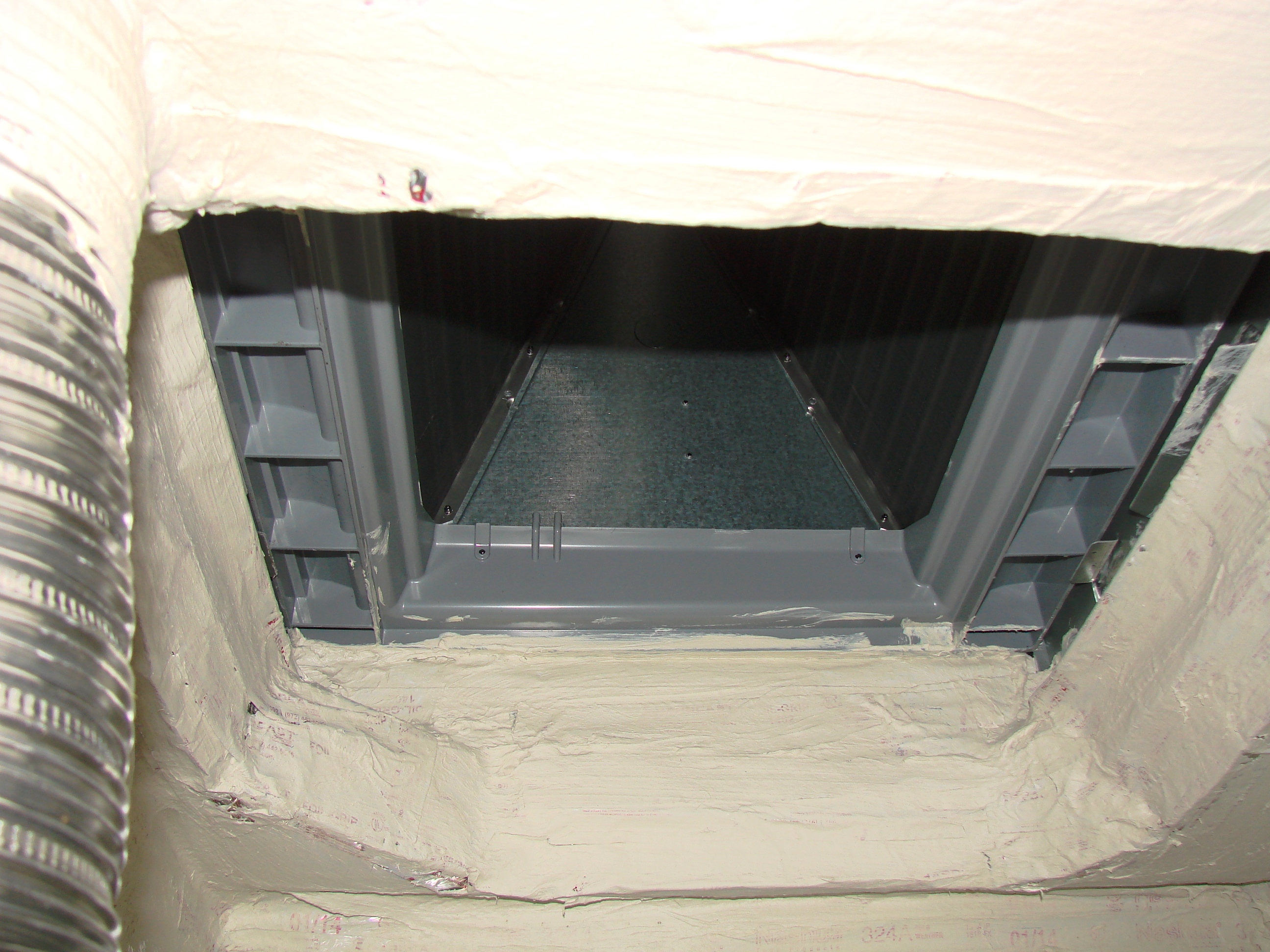
Right – Metal or fiberboard duct is mastic sealed at junction with duct register box
Image
Image
Image
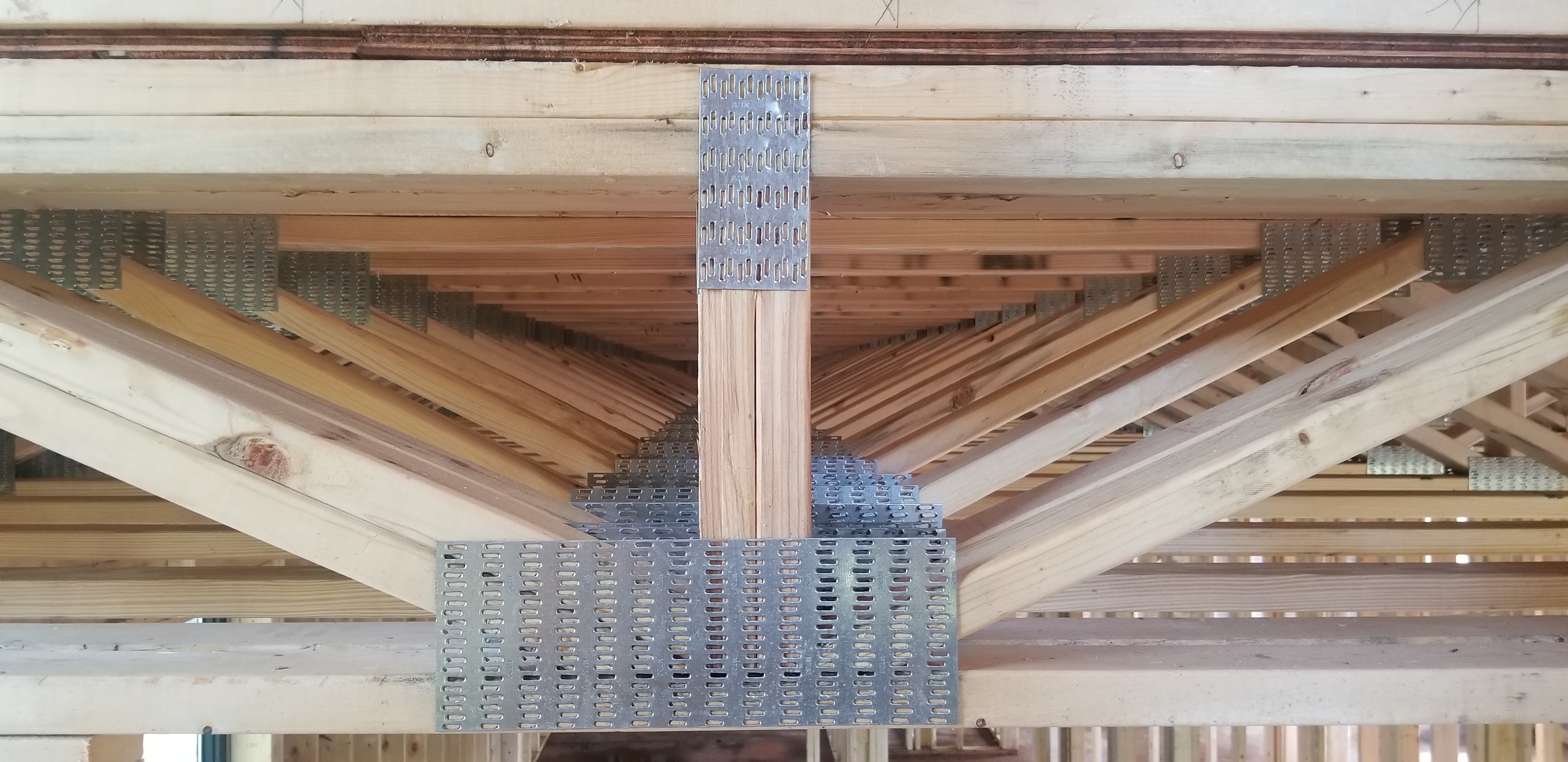
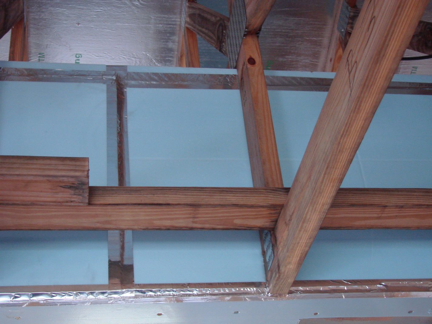
Right – Open web floor joists can provide a space between floors for HVAC ducting.
Image
Image
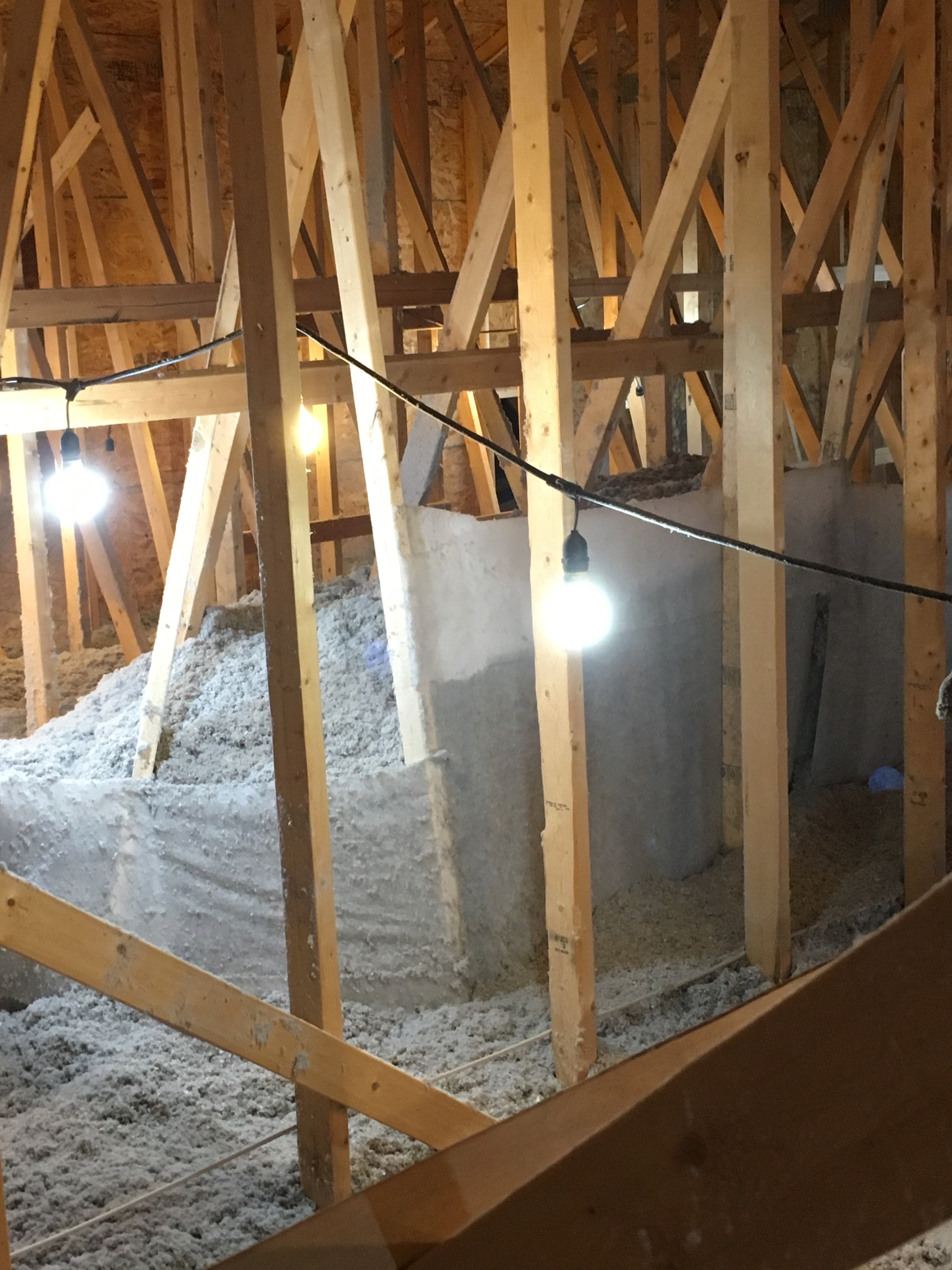
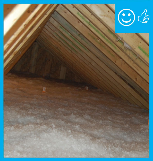
Right – Plastic tenting increases the height of the insulation above ducts that are located in the attic.
Image
Right – R-25 of open-cell spray foam lines this new home’s attic ceiling, to protect HVAC ducts from heat and cold.
Image
Right – Rigid foam is installed behind HVAC ducts to provide additional insulation to the ducts which are installed within the conditioned space.
Image

Right – The hard metal ducts are located in conditioned space between floor joists and all seams are sealed with approved metal tape.
Image
Image

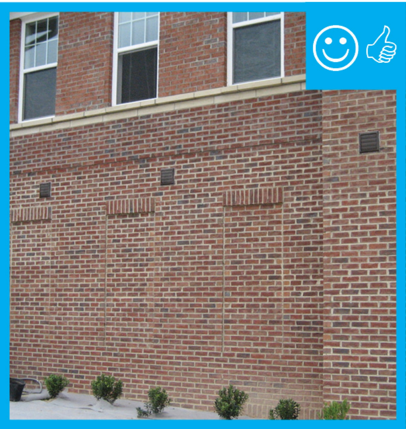
Right – The termination of this kitchen exhaust duct is sealed to the wall to keep out air and water and is screened to keep out pests.
Image

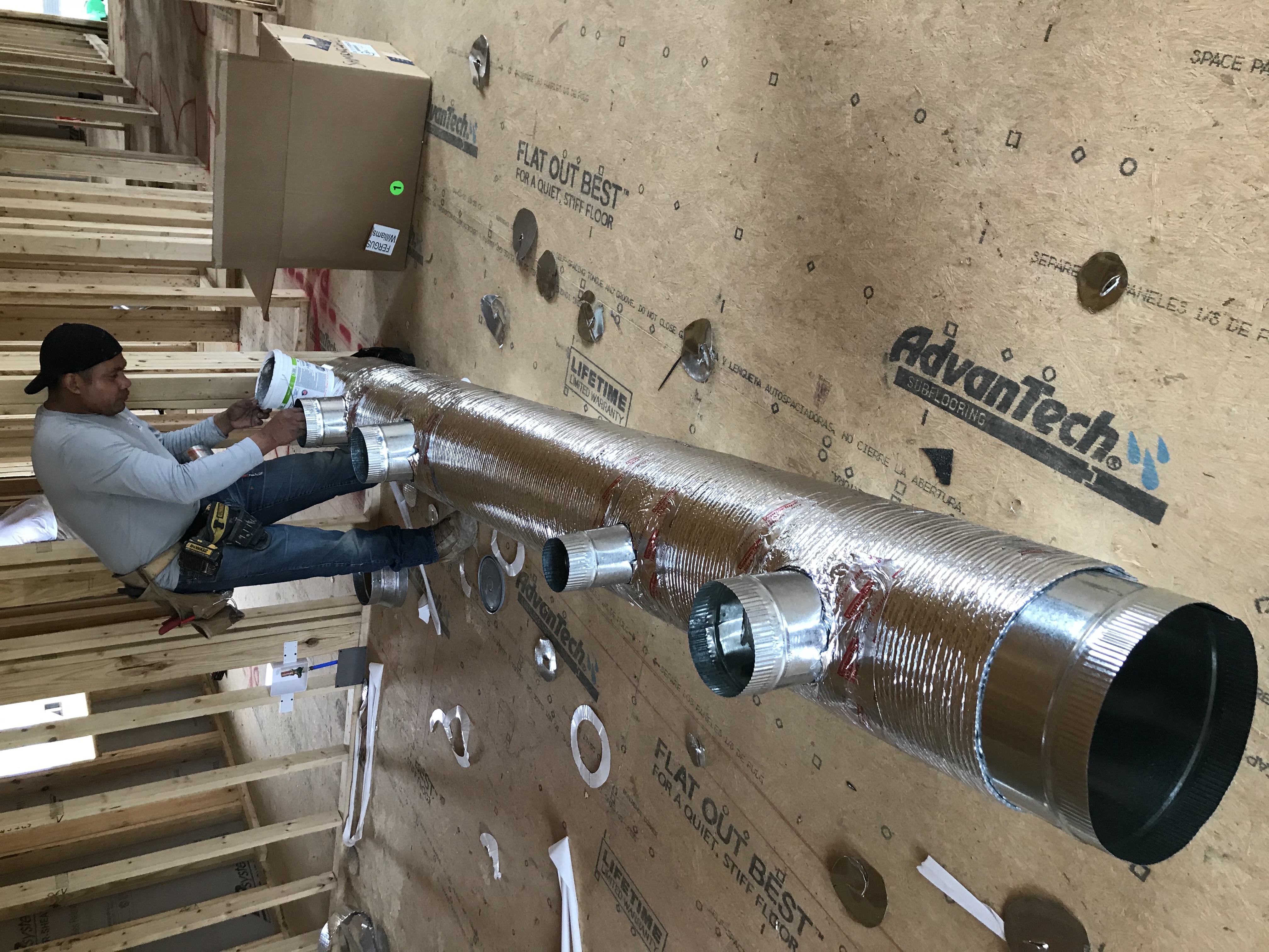
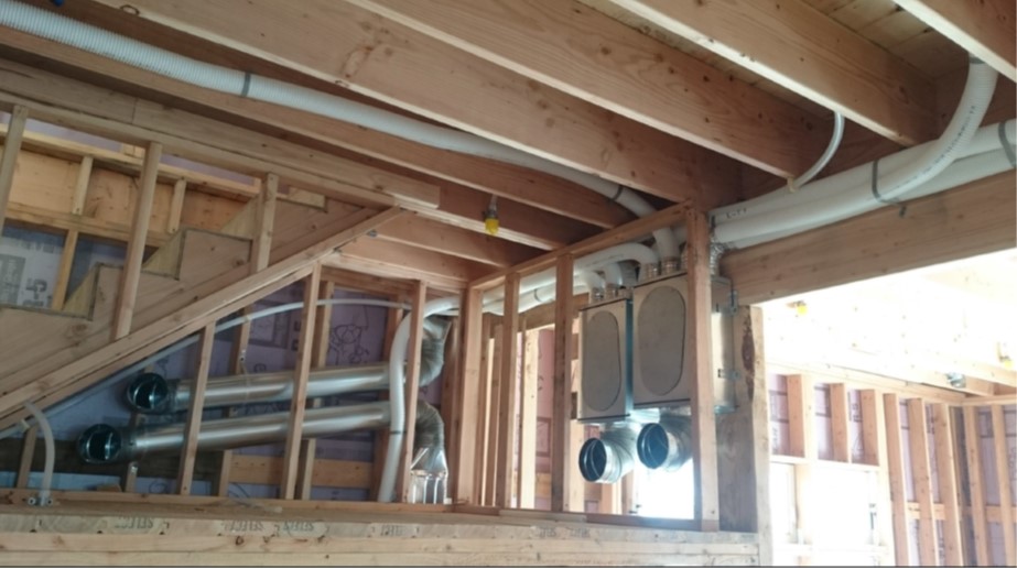
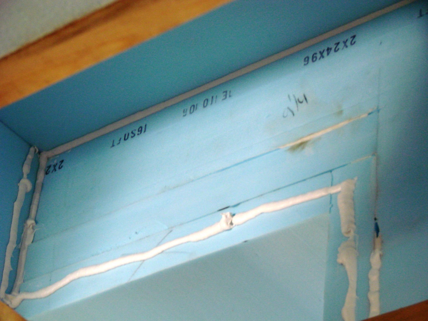
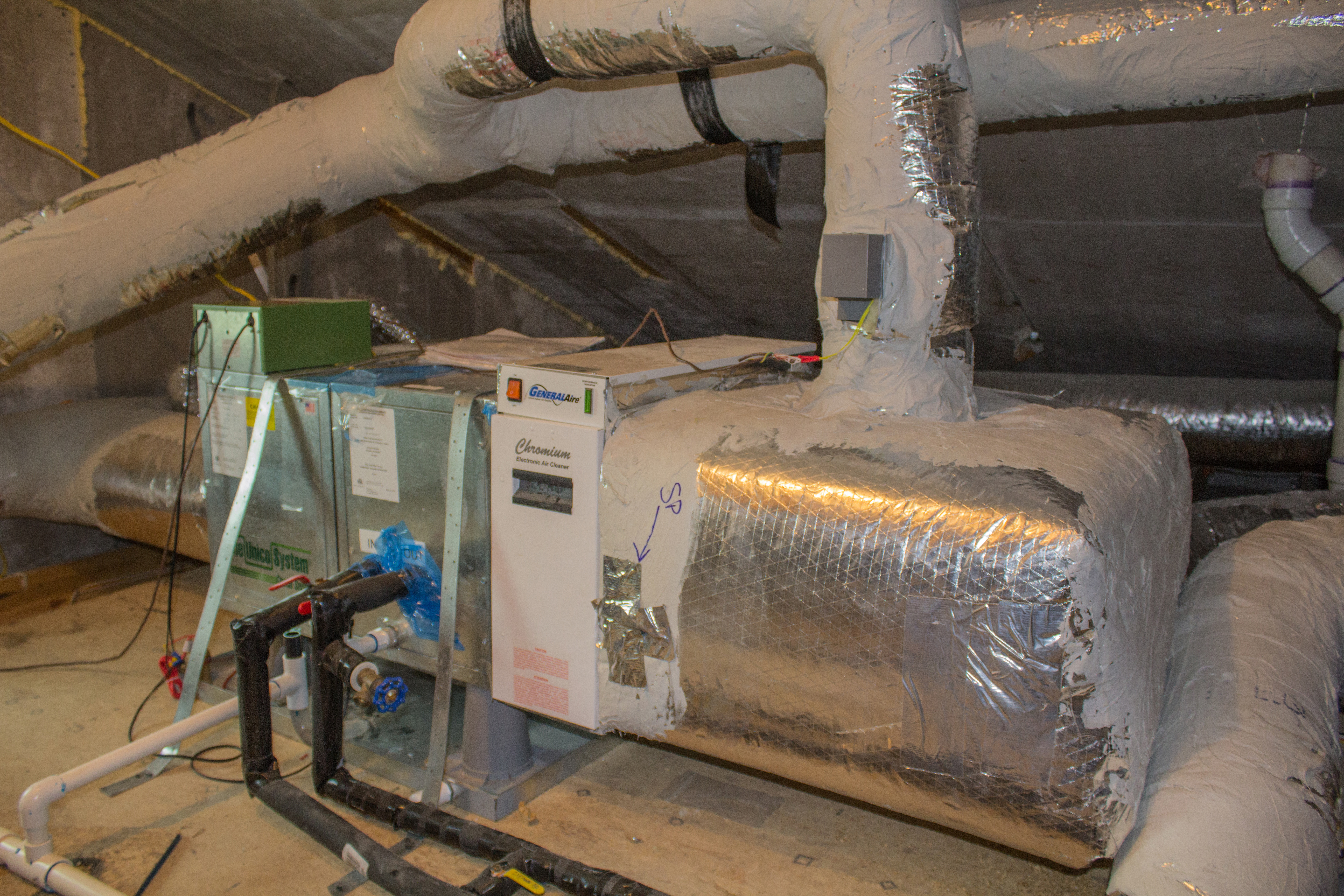
Right – This home uses a small-diameter high-velocity duct system with a main duct (plenum) that is one-fourth the size of a conventional duct and branch ducts with a 2- or 2.5-inch inside diameter.
Image
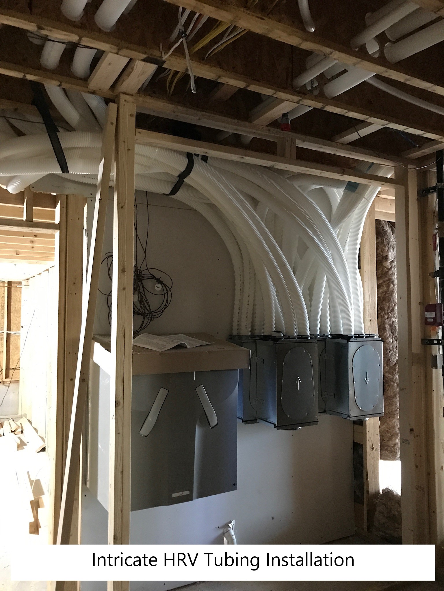
Right – This HRV is ducted separately from the home’s ductless heat pumps to provide filtered fresh air to sleeping and living areas and to exhaust stale air from the bathrooms and laundry.
Image
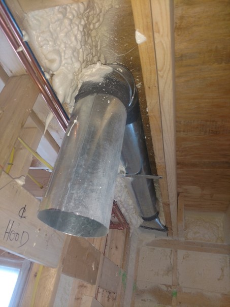
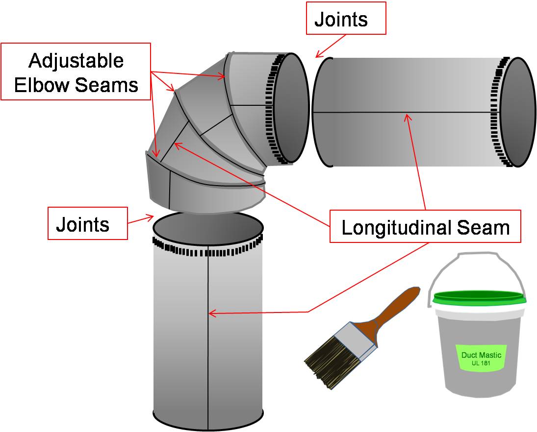
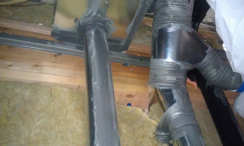
Right – This kitchen exhaust fan duct is made of smooth round steel duct that takes the shortest, most direct route to the outdoors and joints are sealed with mastic.
Image
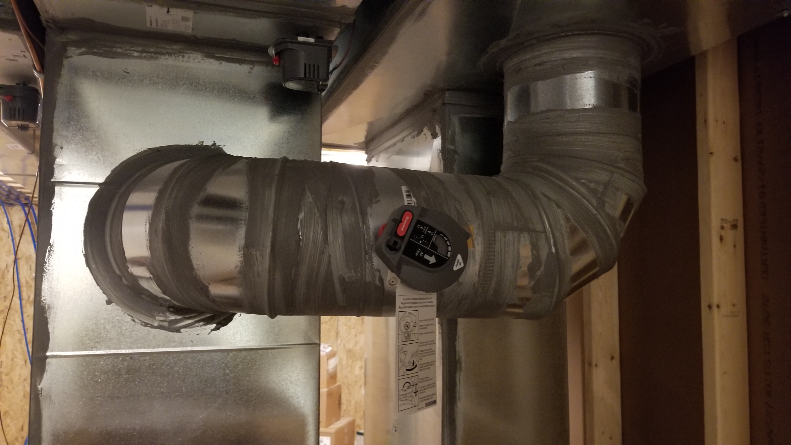
Right – This supply duct is thoroughly sealed at all joints with mastic to prevent air leakage and the duct is equipped with a damper to provide zoned heating and cooling along with other trunk ducts.
Image
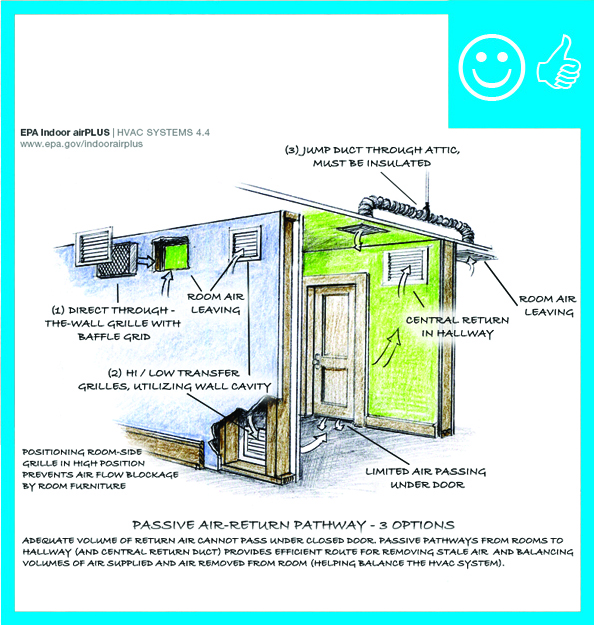
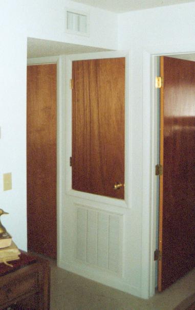
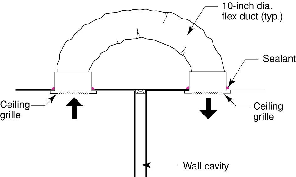
Right – Transfer grilles, Jump ducts, and wall grilles provide passive returns for air returning from bedrooms to the central HVAC system
Image
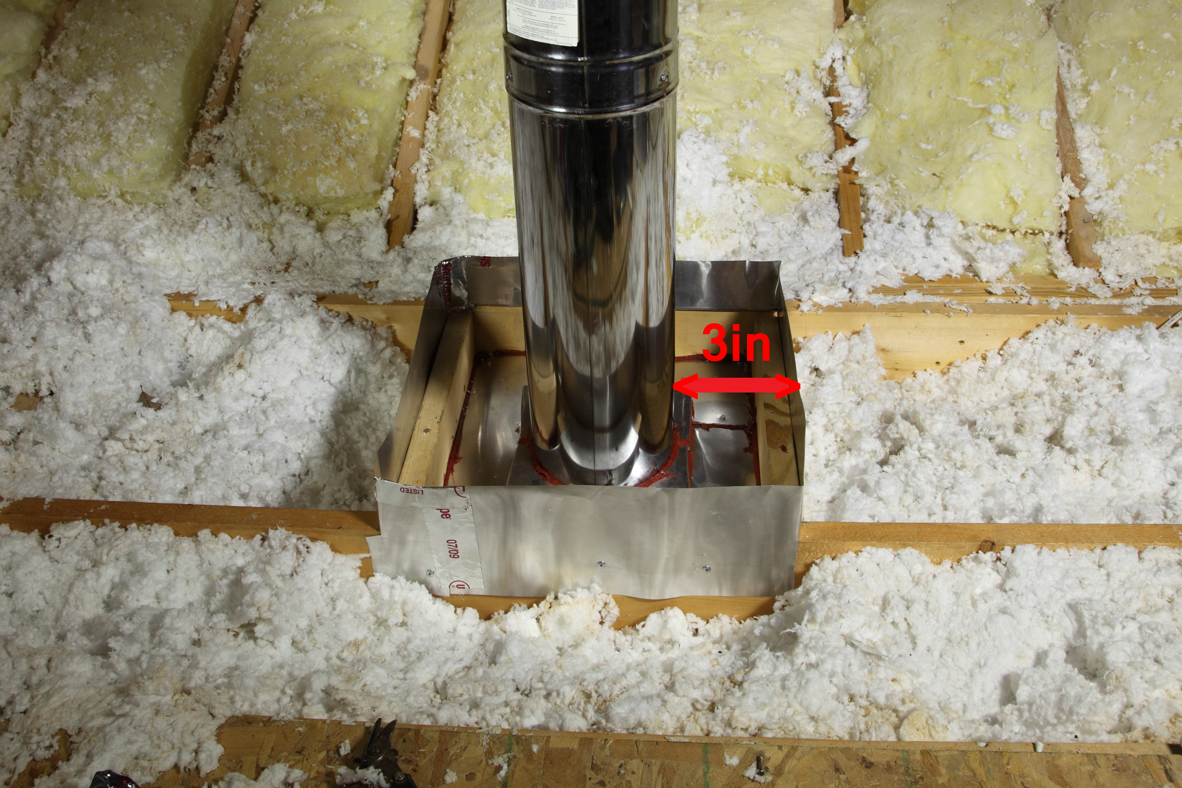
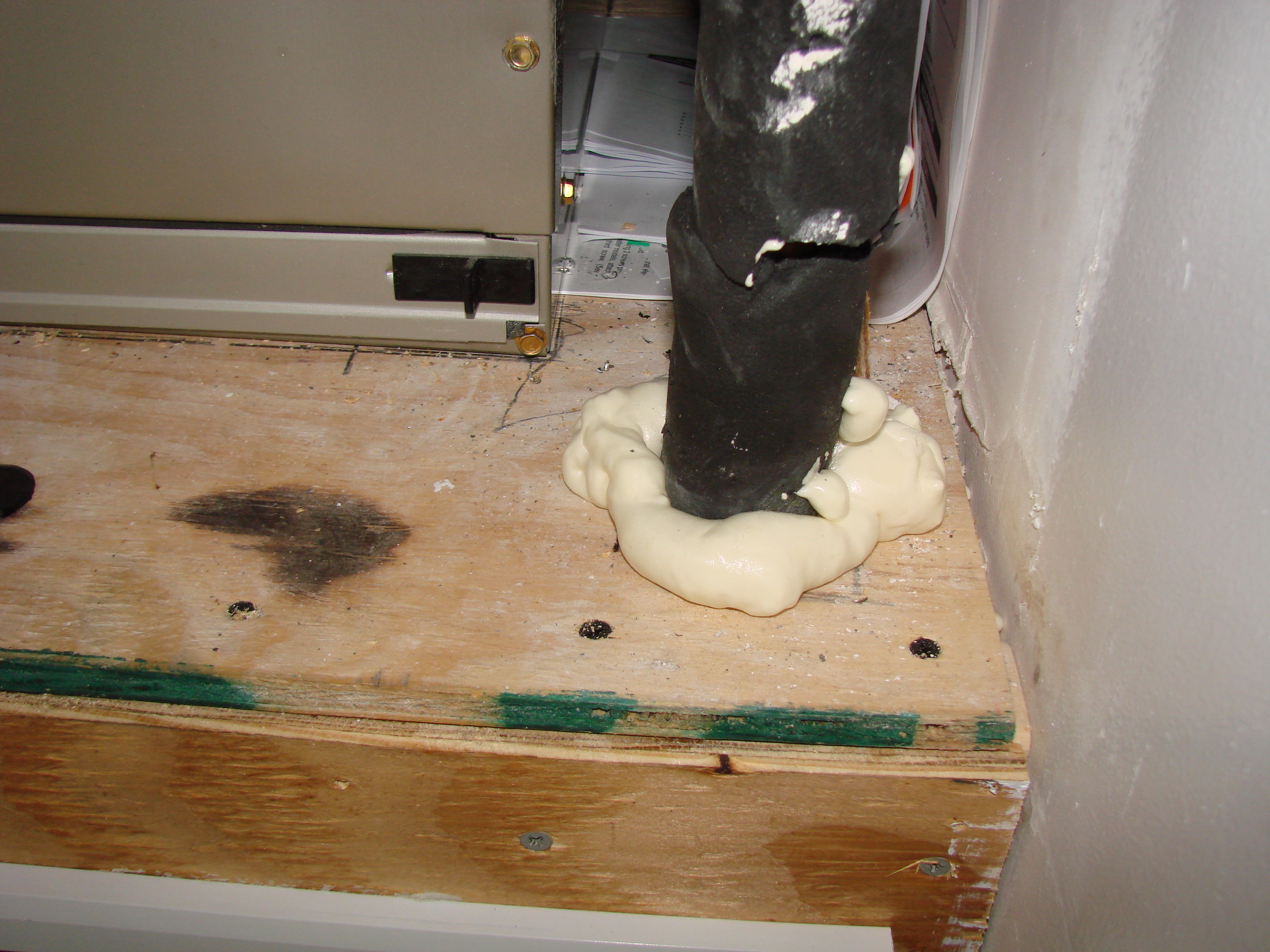
Right- This flue pipe has been air sealed with sheet metal and fire-rated caulk and an insulation dam has been constructed to keep insulation from touching the hot flue pipe
Image
Right: A well-constructed air handler closet
Image

Right: Air seal all seams in the return air plenum before installing a new air handler
Image
Right: Ducts are completely buried beneath insulation to the depth specified in the plans
Image
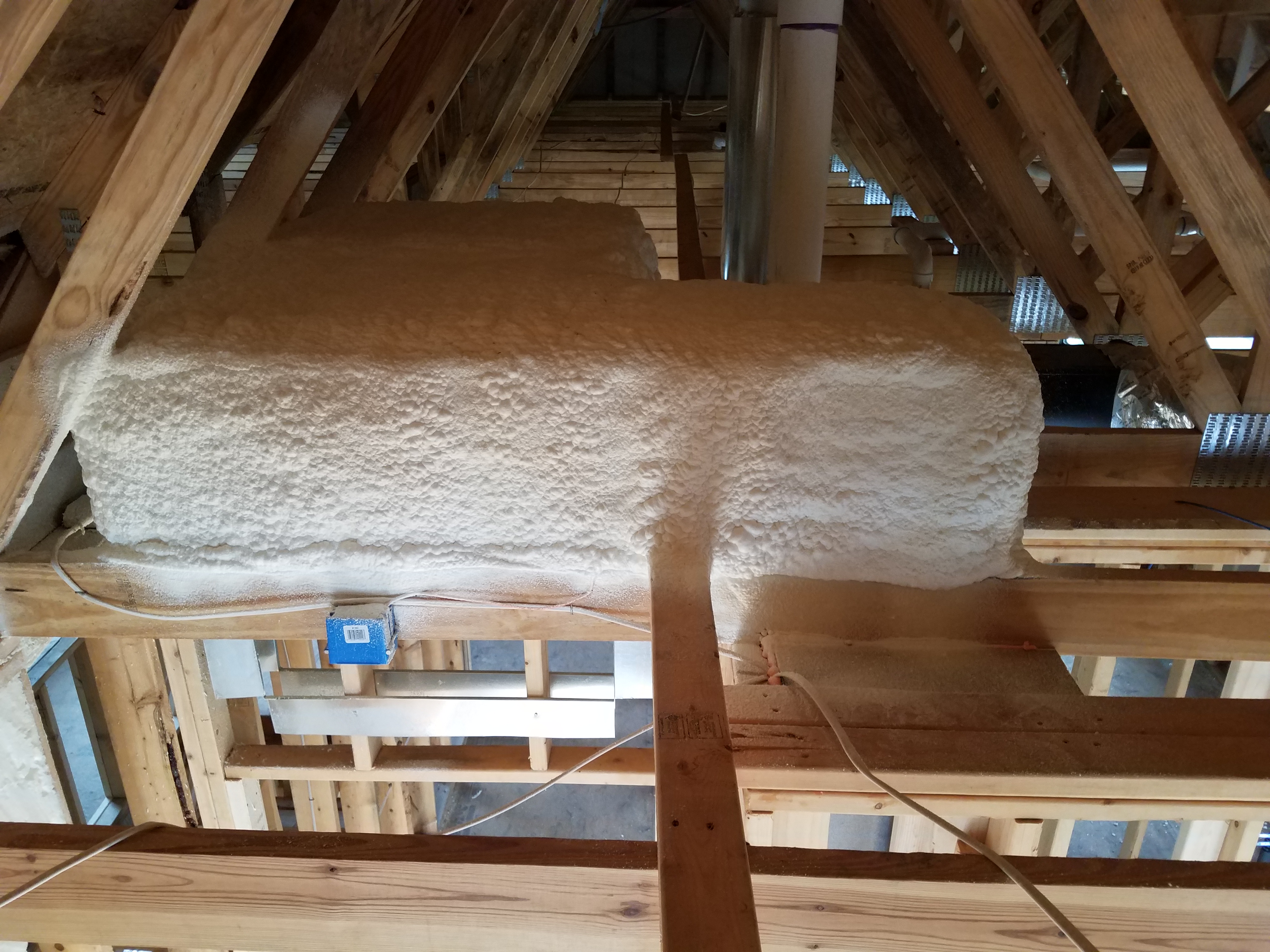
Right: ductwork is fully encapsulated with ccSPF prior to ceiling installation and burial
Image
Right: Ductwork is installed in direct contact with lower truss cords. In this picture the main trunk is laying on the truss cords and branch ducts are temporarily held with strapping across truss cords. Ducts are well sealed with mastic
Image
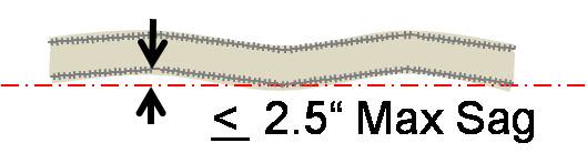
Right: If existing straps are narrower than 1.5 inches, add sheet metal saddles to keep the duct from sagging and pinching
Image
Right: Refrigerant piping is sealed where it exits the return plenum
Image
Image

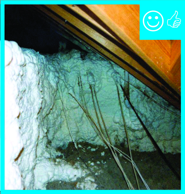
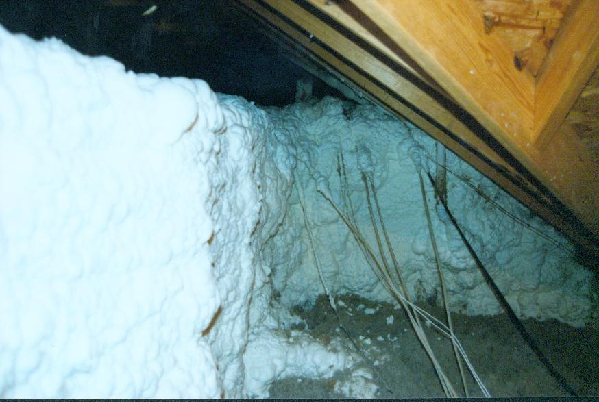
Right: Spray foam air seals and insulates raised ceiling duct chase
Image
Right: The bottom of the air handler cabinet is well sealed to the return platform
Image
Right: The plenum liner is well sealed to the filter-backed grille
Image
Right: Use mastic to air seal the return air plenum and to seal around refrigerant lines coming from the slab in the floor of the return
Image
Run-out duct is sealed with mastic
Image
Run-out ducts are installed over partition walls
Image
Image
Image
Image
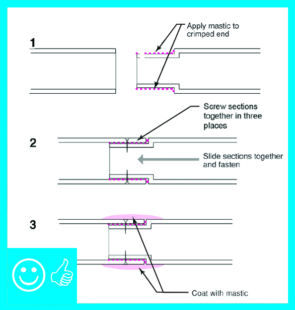
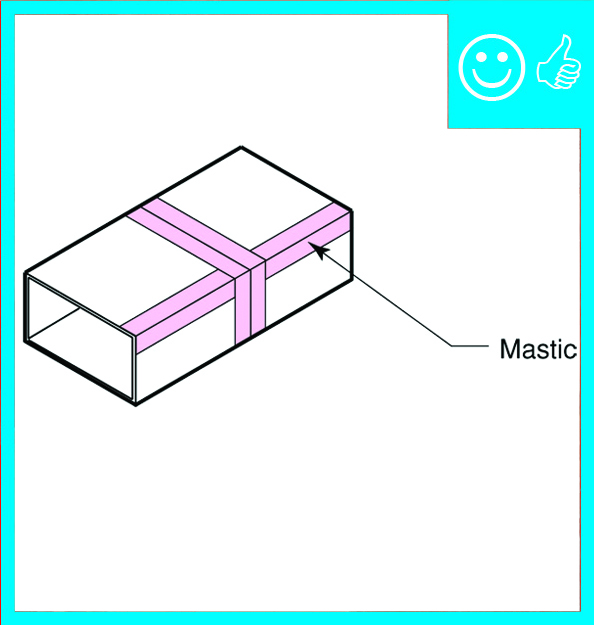
Seal all joints and seams in the metal ductwork with mastic before installing insulation
Image
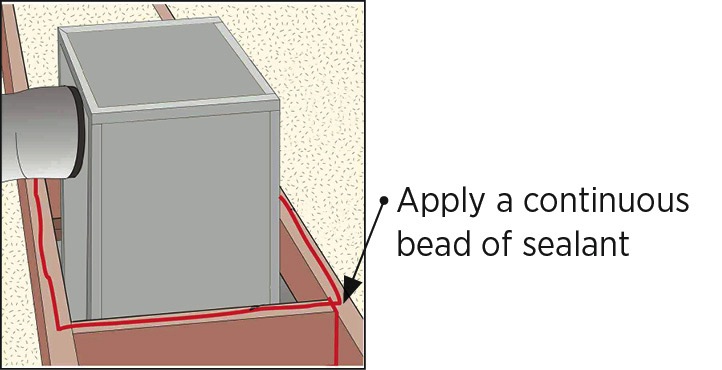
Seal all wood framing joints surrounding the chase with sealant and lay a bead of sealant along top edge of chase framing
Image
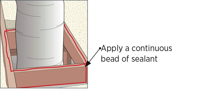
Seal all wood framing joints surrounding the chase with sealant and lay a bead of sealant on top edge of chase framing
Image
Seal bottom layer of rigid insulation with adhesive, tape and nails
Image
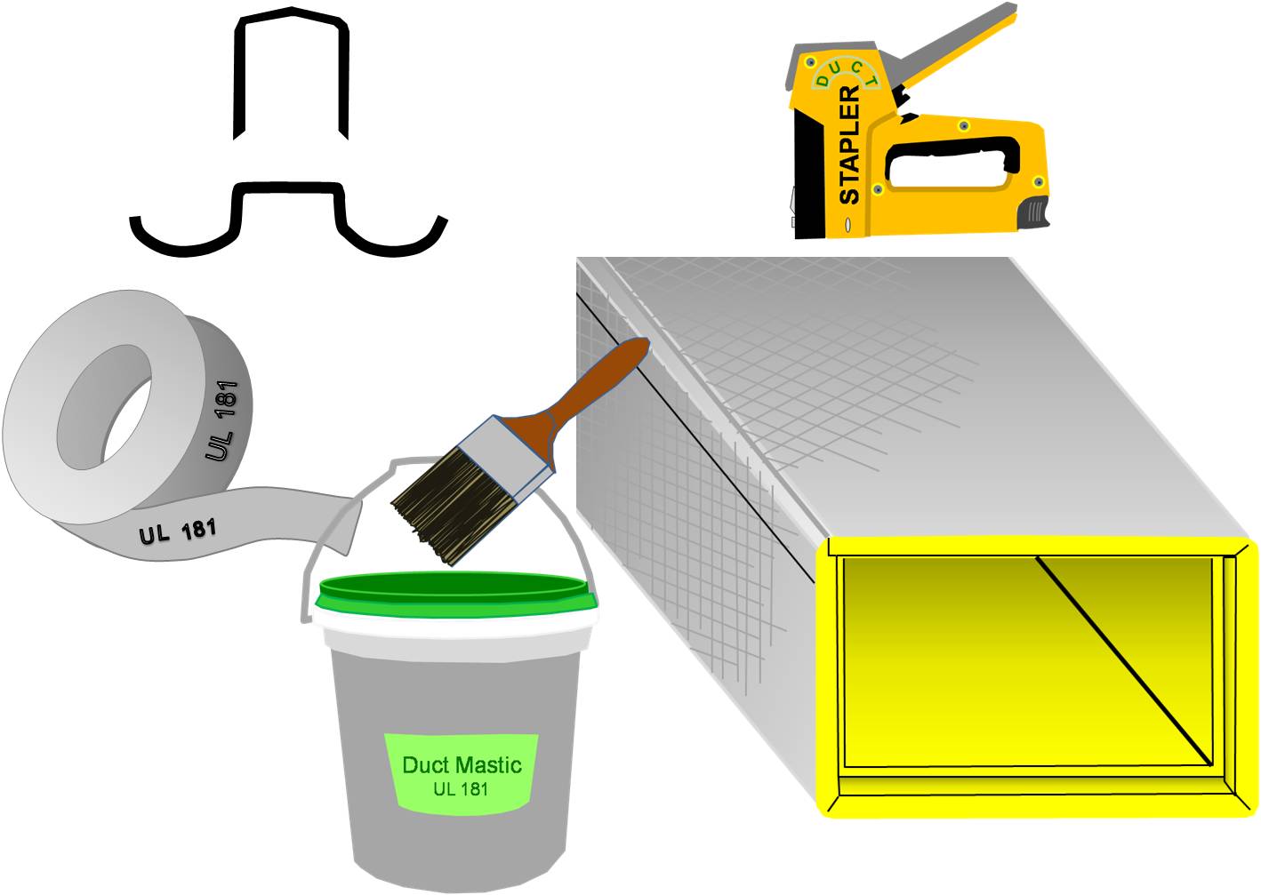
Seal seams in fiber board ducts with out-clinching staples, UL-181A-approved tape, and mastic
Image
Image
Second layer of rigid insulation is adhered with foam
Image
Seperate dwellings with their own seperate exhaust terminations
Image
Image
Some builders create pan joists by attaching a solid sheet good to the bottom of a floor joist to create a return air pathway
Image
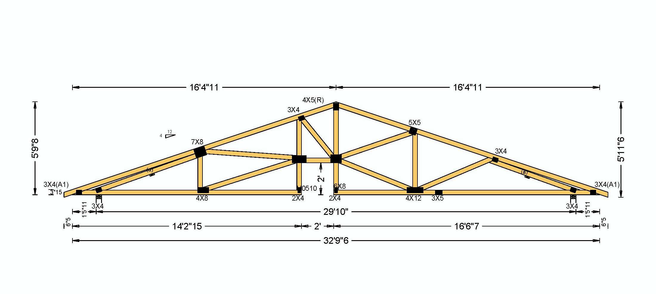
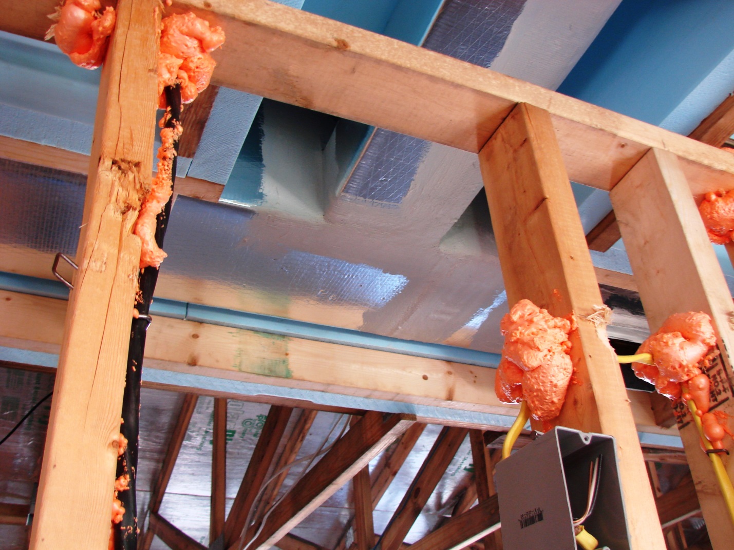
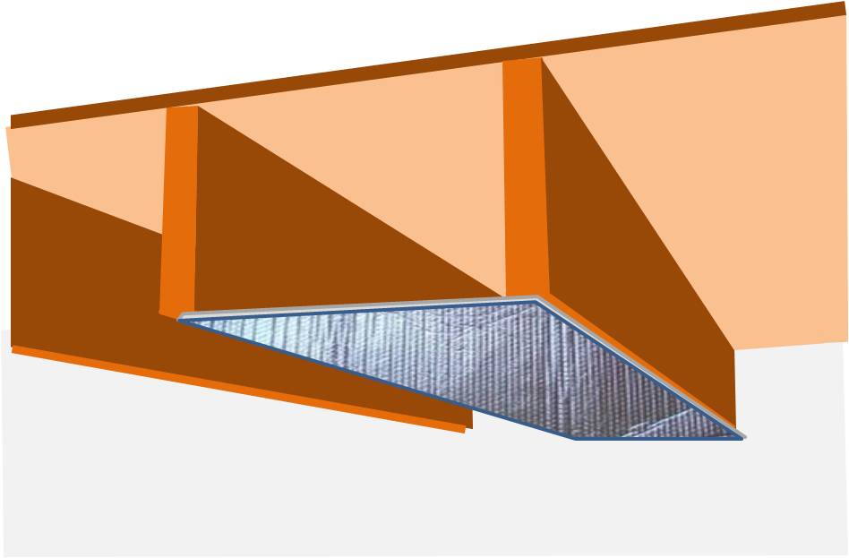
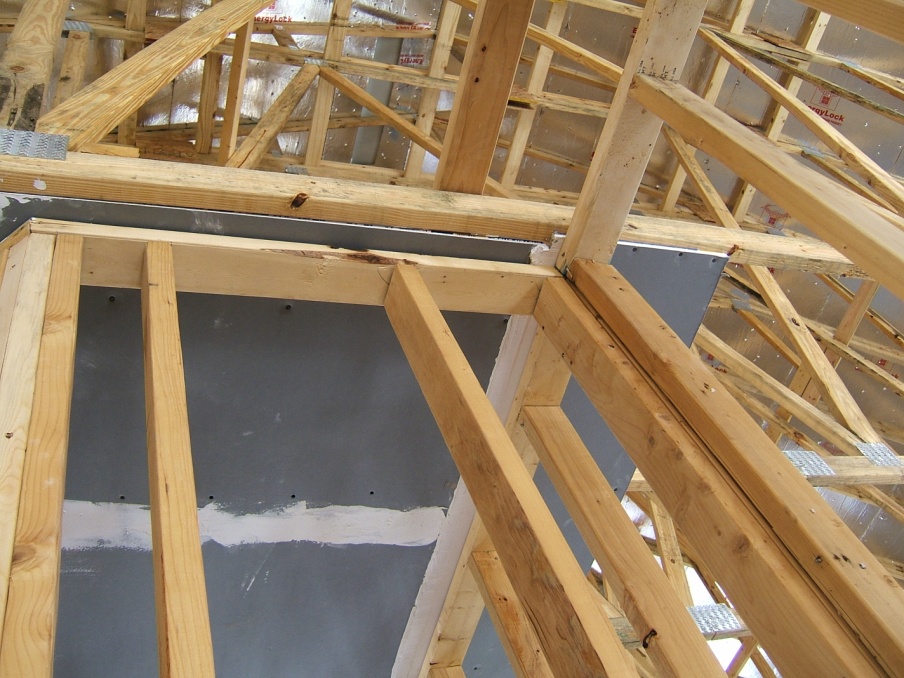
Specially designed roof trusses come with a two-foot by two-foot notch cut next to the center post providing space to install an insulated duct chase inside the home’s conditioned space but above the normal ceiling height.
Image

Image
Image
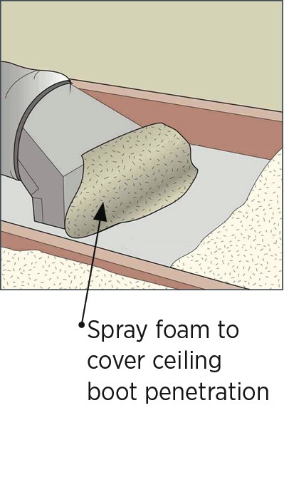
Spray foam insulation used for raised ceiling duct chase
Image
Spray foam insulation used for raised ceiling duct chase.
Image
Standard 2 in. by 4 in. stud secures duct chase - made of rigid insulation in this example
Image
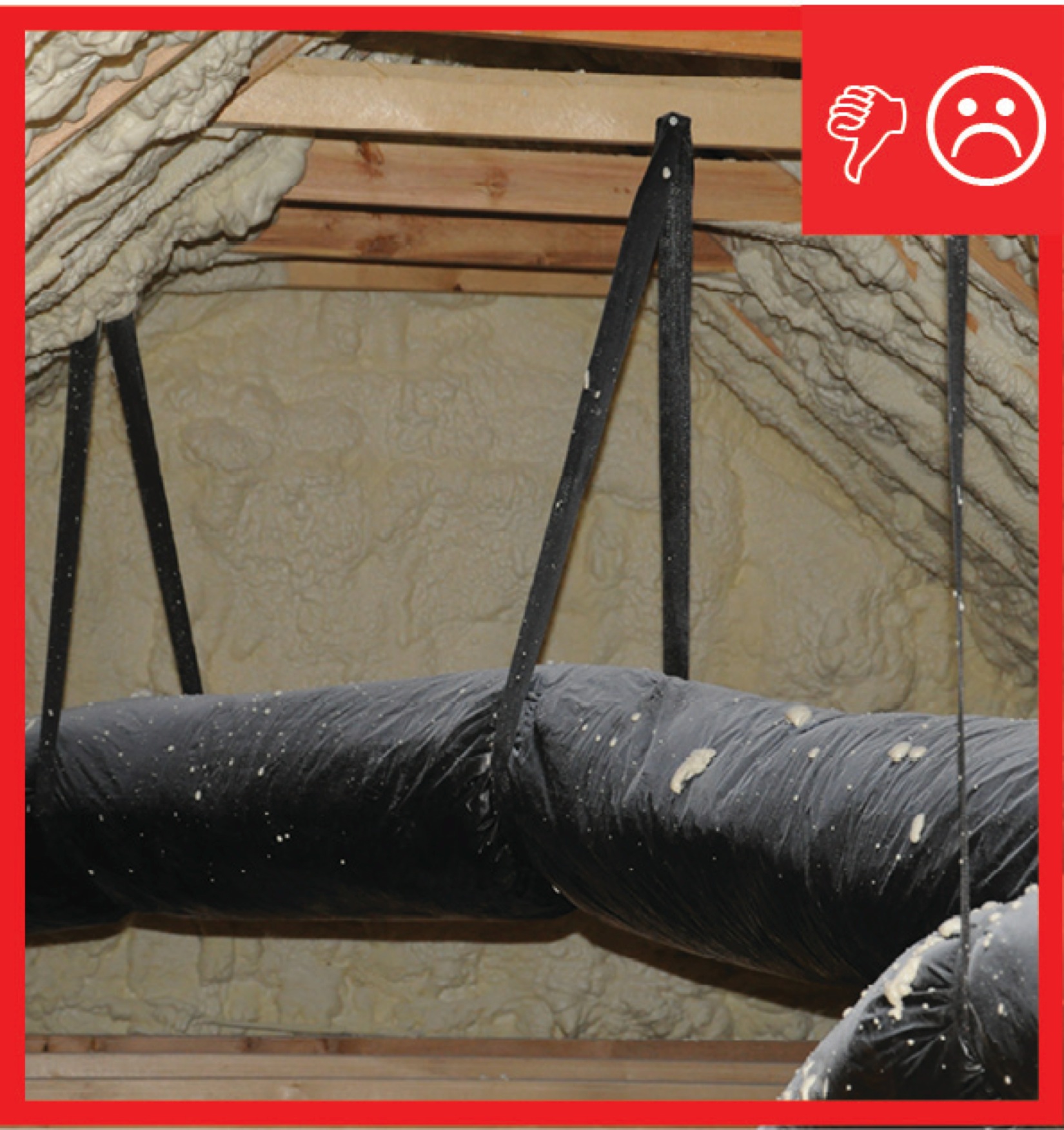
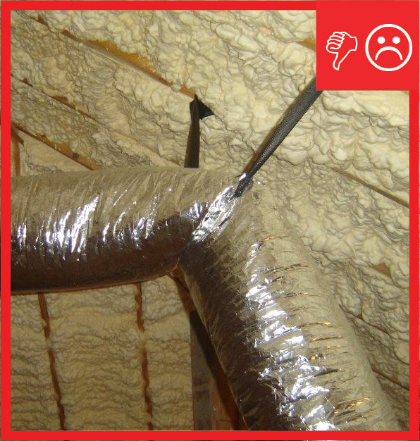
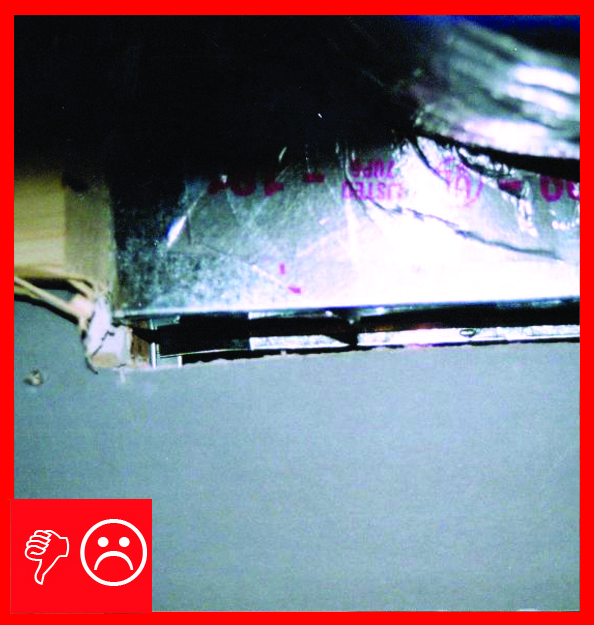
Straps are spaced too far apart causing the straps to compress the duct under its own weight
Image

The AC unit has a drip pan and automatic shutoff in case the condensate drain gets clogged.
Image
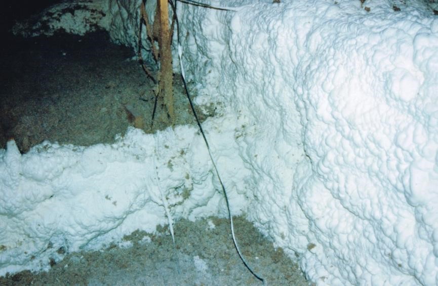
The attic duct chase insulated and sealed to the attic floor with spray foam
Image
The attic is sealed and insulated along the underside of the roof deck with 5.5 inches of polyurethane spray foam, providing conditioned space for the HVAC system.
Image
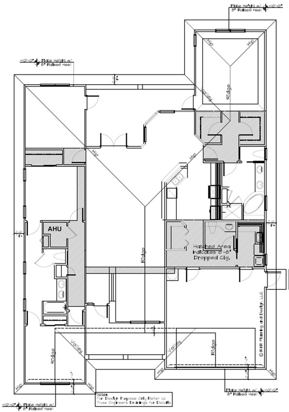
The chase is laid out on the plans (grey highlighted areas) to aid sub-contractors to execute the design
Image
The drywall above the chase extends beyond adjoining top plates for a continuous air barrier
Image
The drywall above the dropped ceiling duct chase extends beyond adjoining top plates for a continuous air barrier
Image
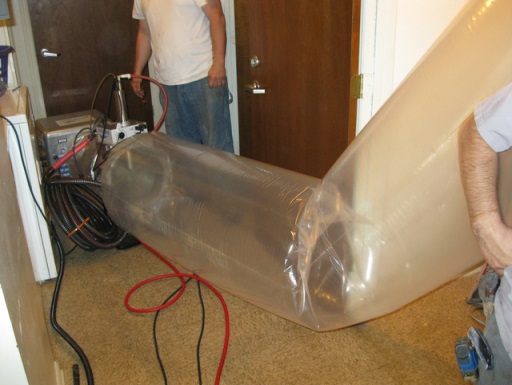
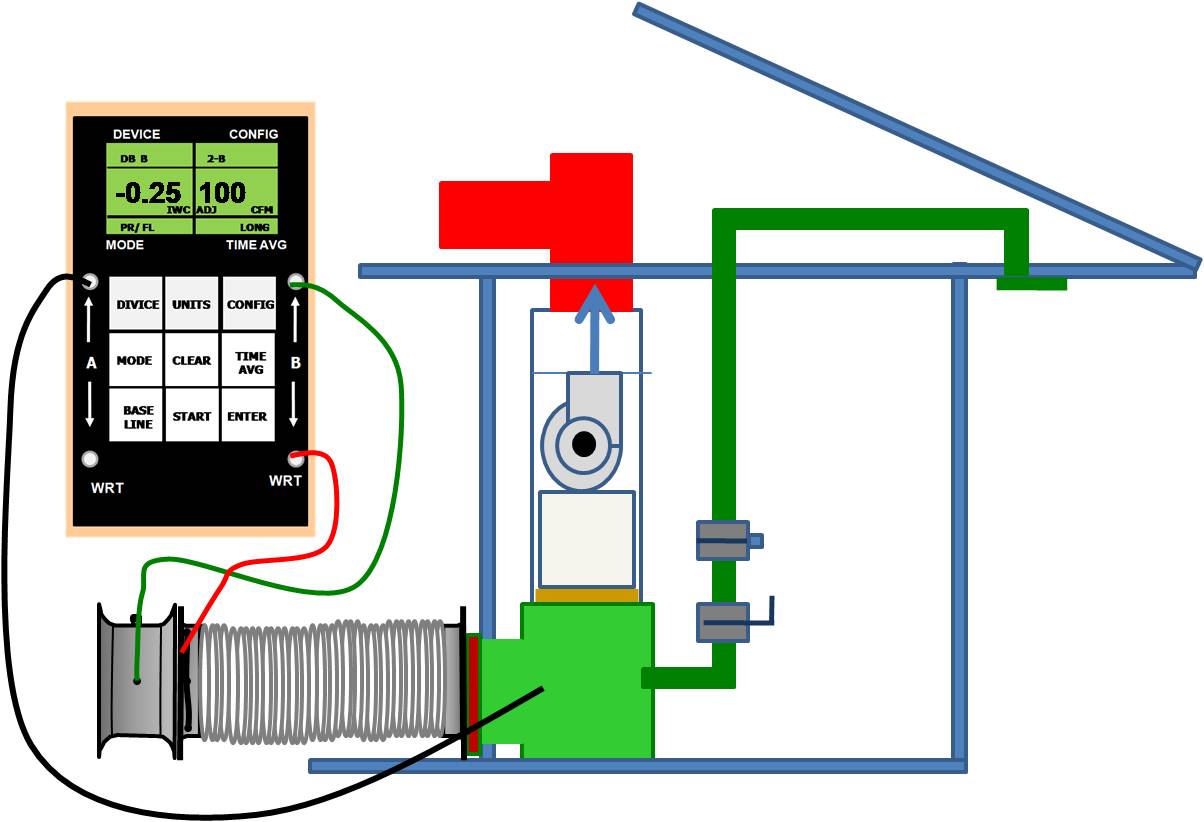
The duct sealing spray injection system application tunnel inflates as the injection system operates
Image
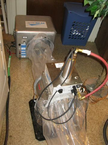
The duct sealing spray injection system includes a blower/heater (background) and the sealant injection unit (foreground)
Image
Image
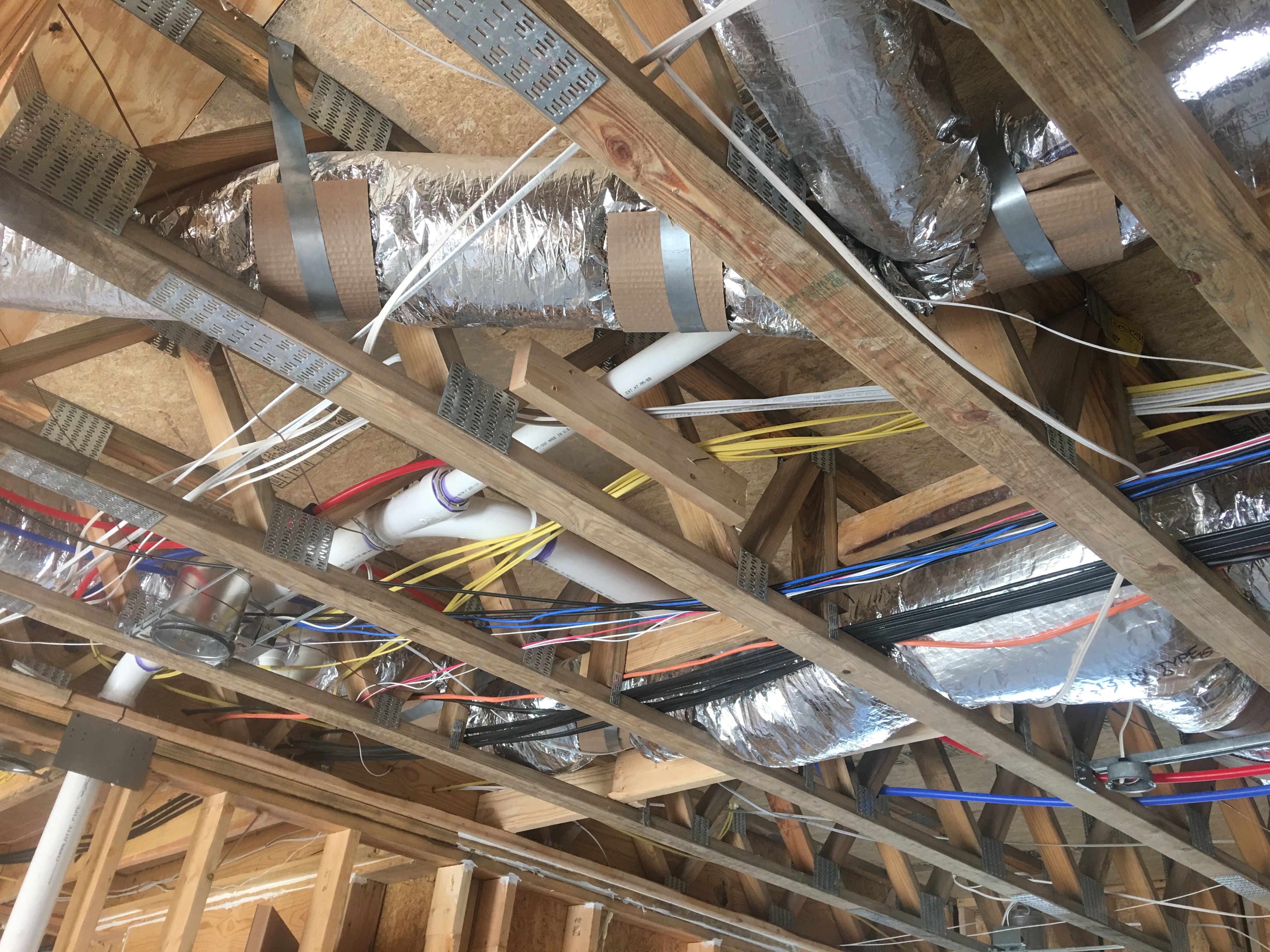
The ducts are located in conditioned space in open-web joists between the floors and supported to prevent sagging.
Image
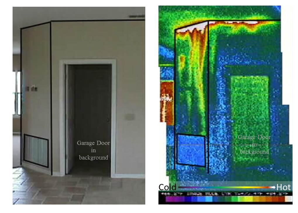
The grille in the photo on the left brings air into a return air plenum under an air handler platform. As shown in the infrared image on the right, the plenum is not air sealed so hot attic air is being pulled into the air handler closet.
Image
Image
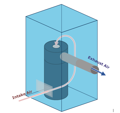
The heat pump water heater’s evaporator fan provides enough air movement for active ventilation of a small room when the exhaust is ducted; intake air enters passively through a wall grille
Image
The high-efficiency air-to-air heat pump is set in an overflow pan with an emergency shut off sensor in case the condensate tube were to clog and cause condensate to fill up the pan.
Image
Image
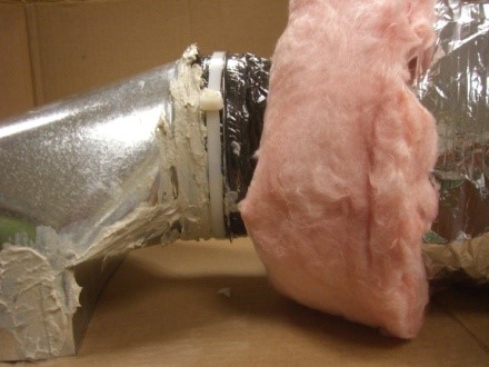
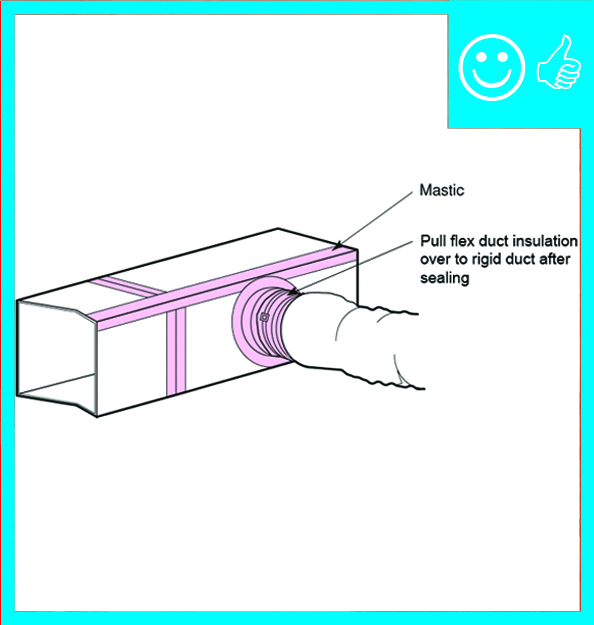
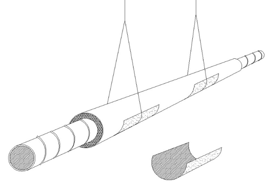
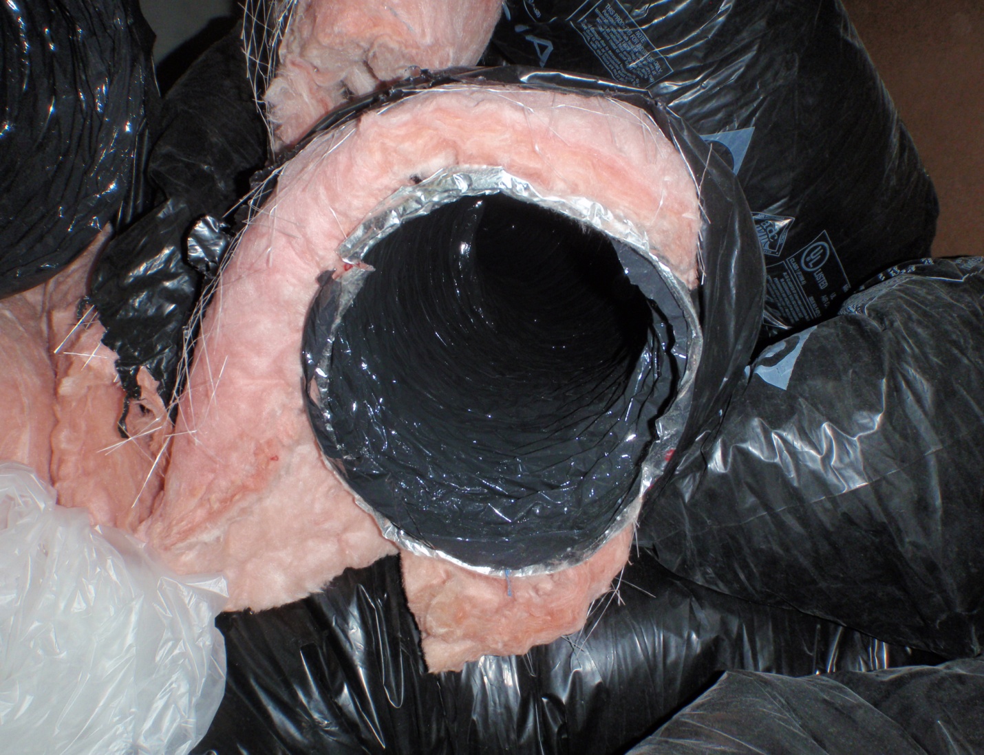
The inner liner of the flex duct is fastened to the collar with a tension tie, the connection is sealed with mastic, then the outer layer is pulled over and sealed with mastic or foil tape (Steven Winter Associates 2013).
Image
Image
Image
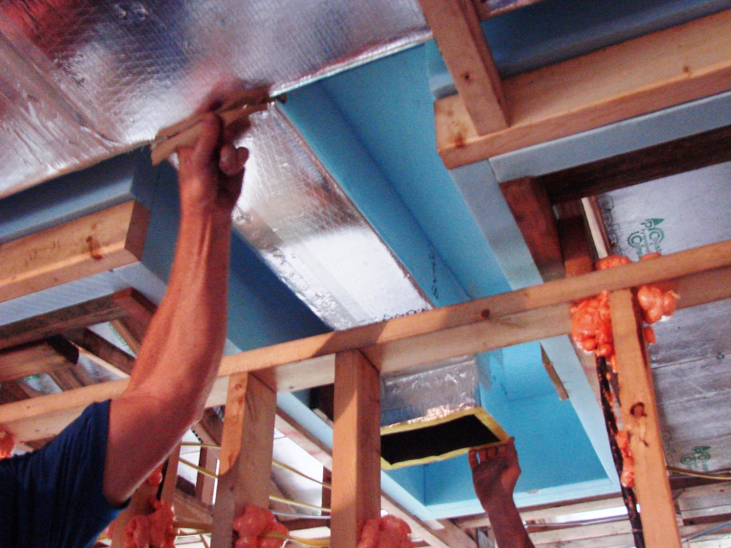
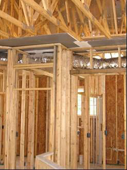
The main trunk line of the ducts runs within an insulated duct chase installed in a notch designed into the roof trusses that runs the length of the home to provide supply air directly to most of the home’s ceiling registers.
Image
Image
The sealed, insulated crawlspace is a clean, dry location to house the main floor heating ducts and also provides bonus storage space.
Image
Image
Image
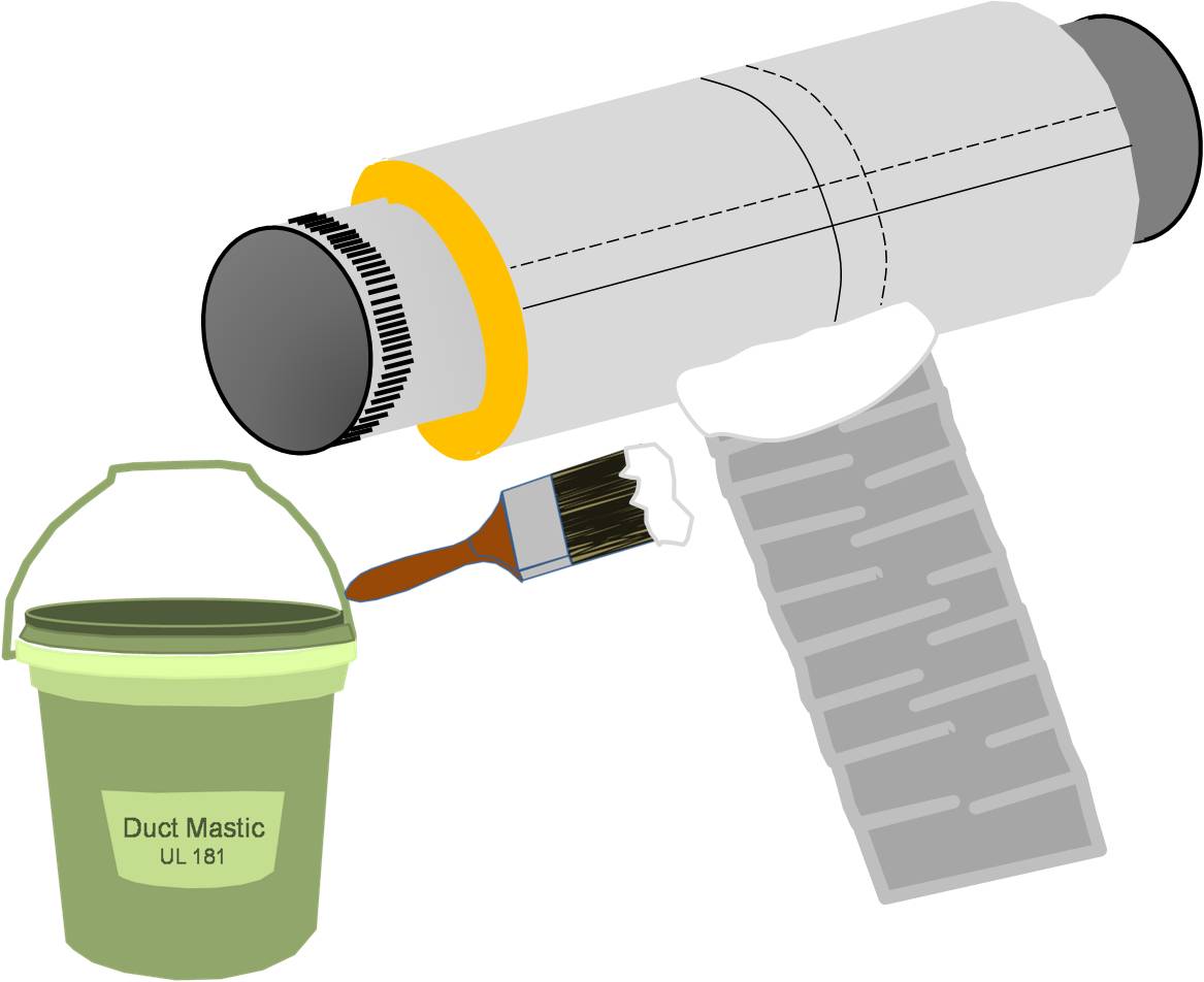
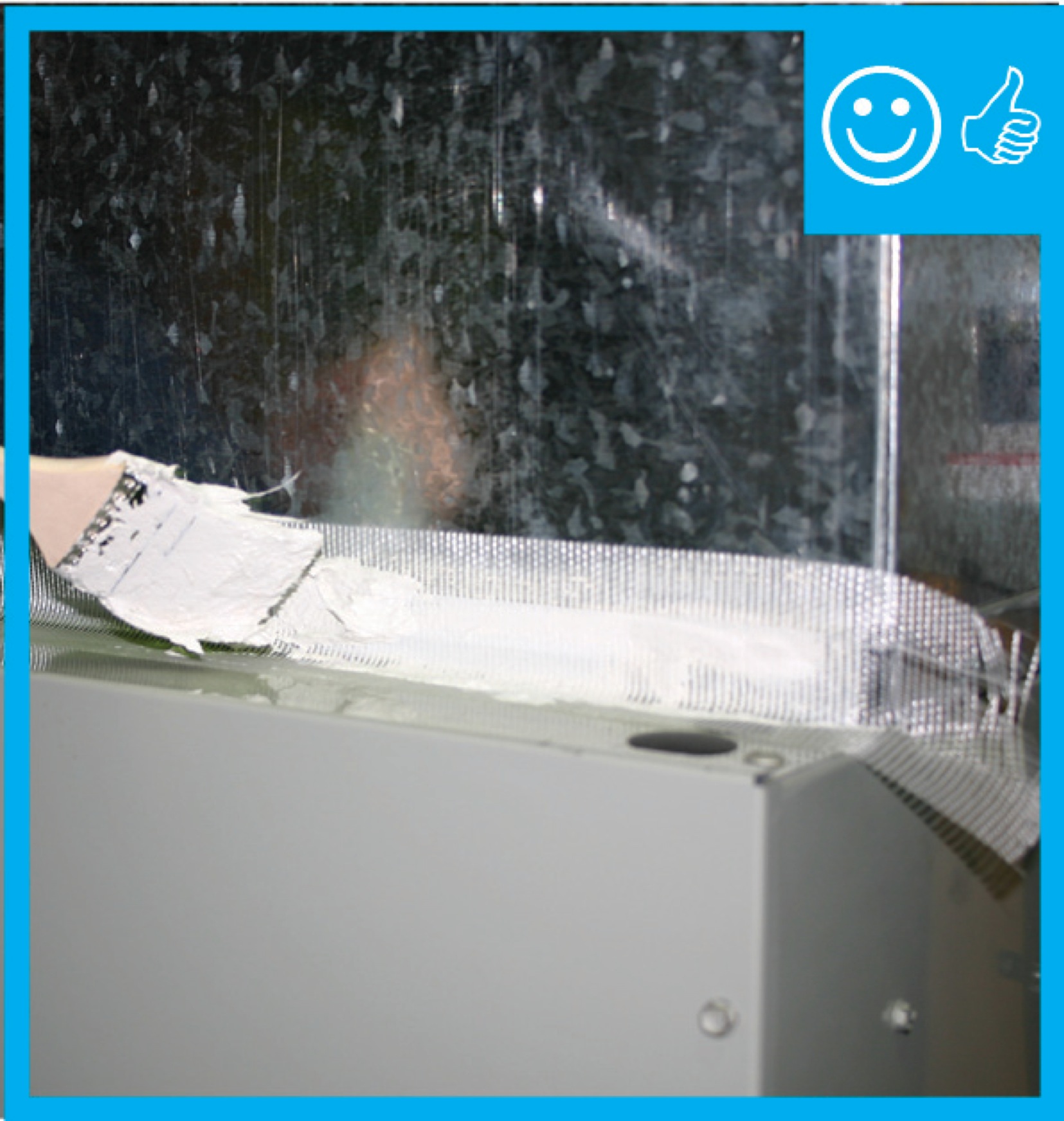
The tape is covered with mastic to ensure an airtight seal between the duct and the fitting
Image
Image