Showing results 101 - 200 of 422
Image
Image
Image
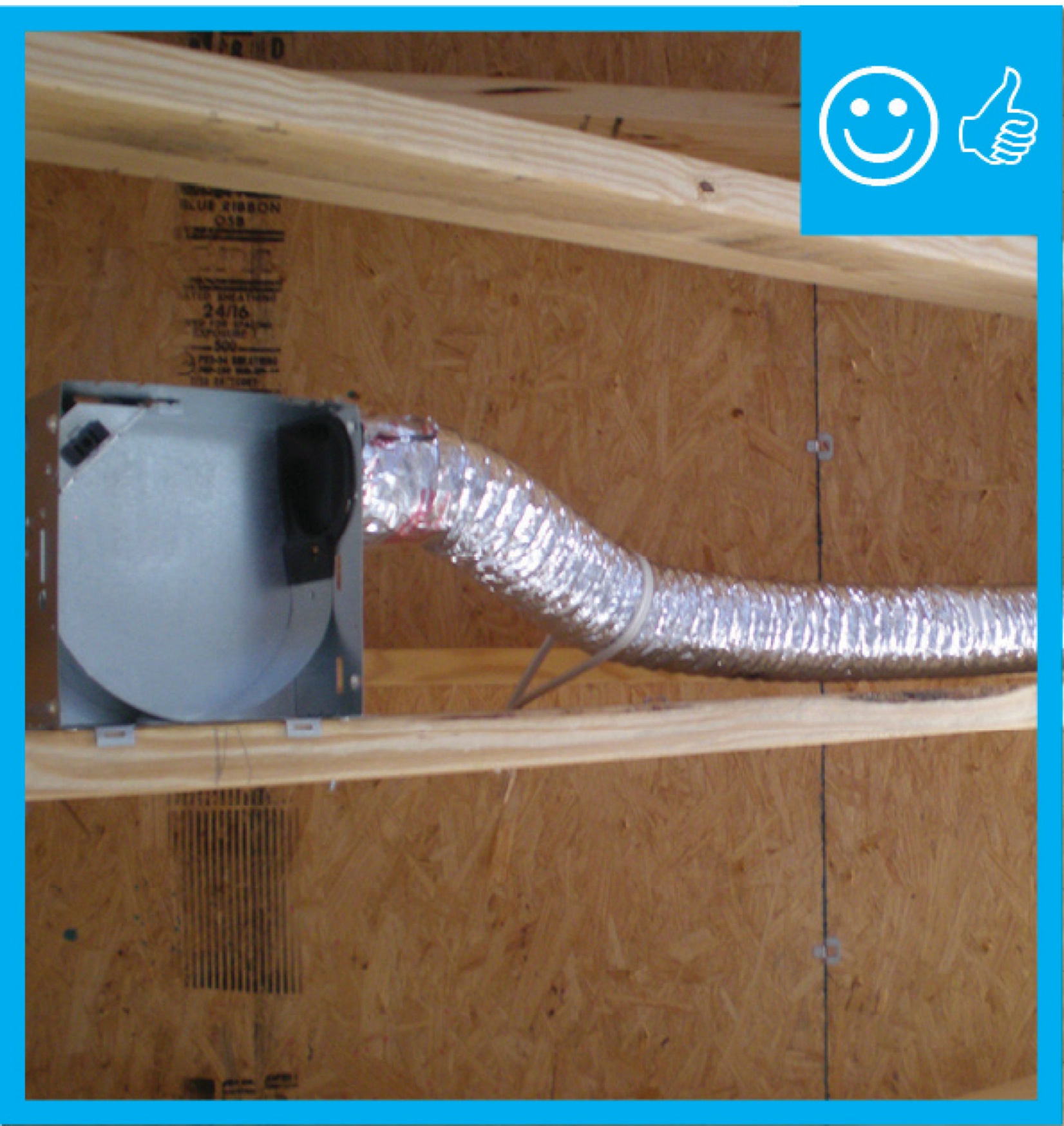
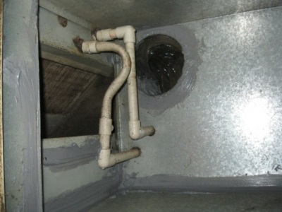
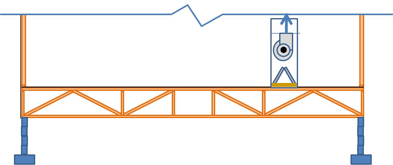
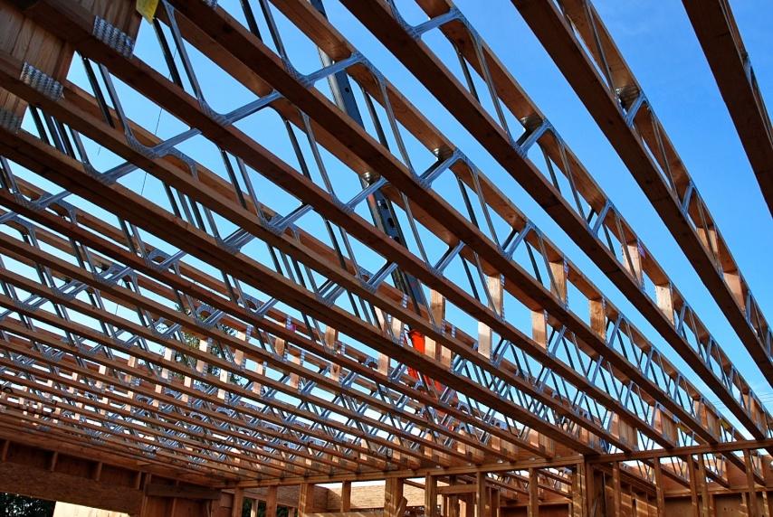
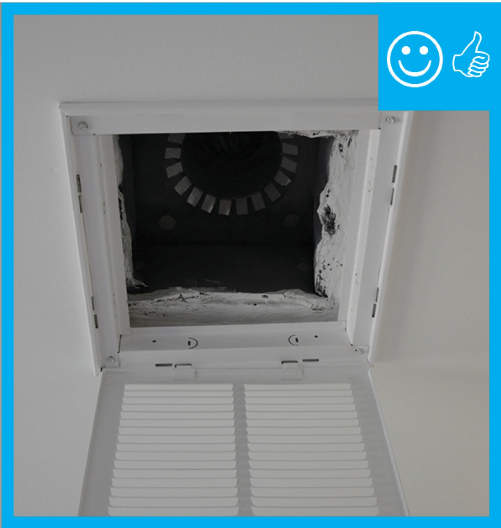
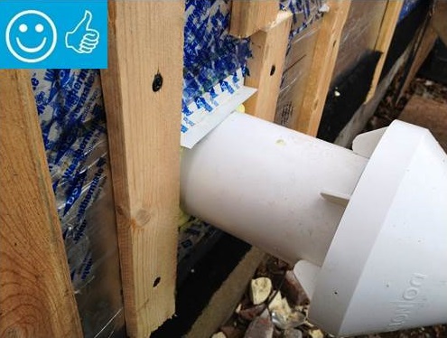
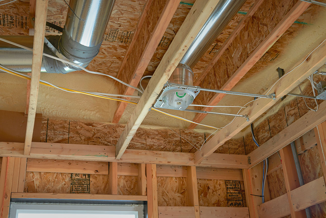
Fan housing was oriented in the correct direction to allow proper exhaust duct installation
Image
Image
Image
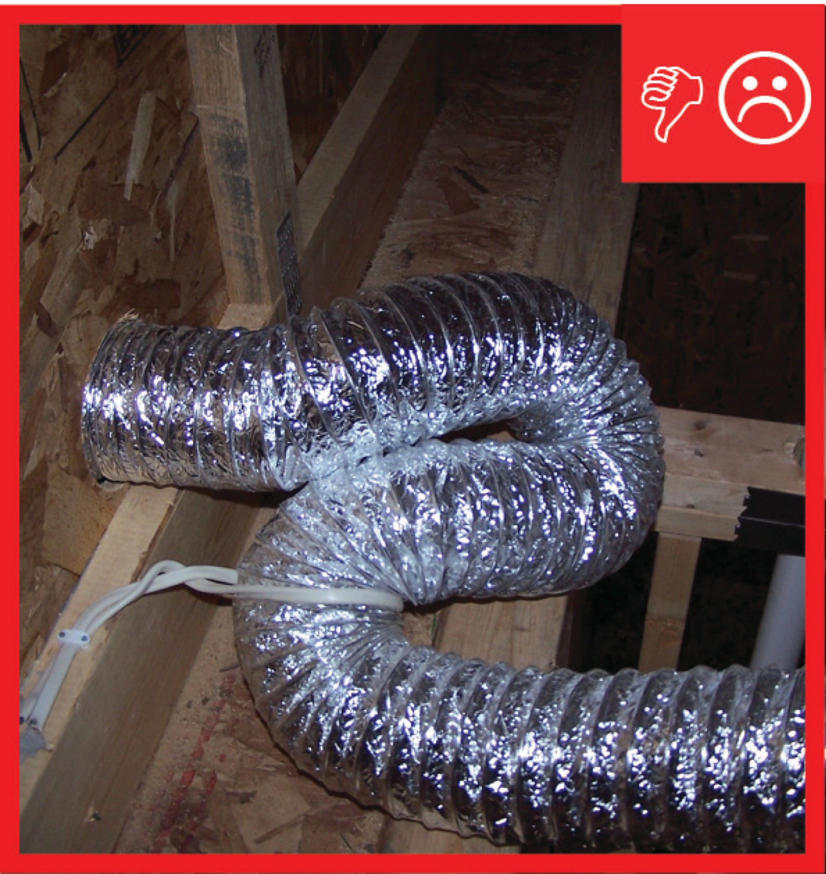
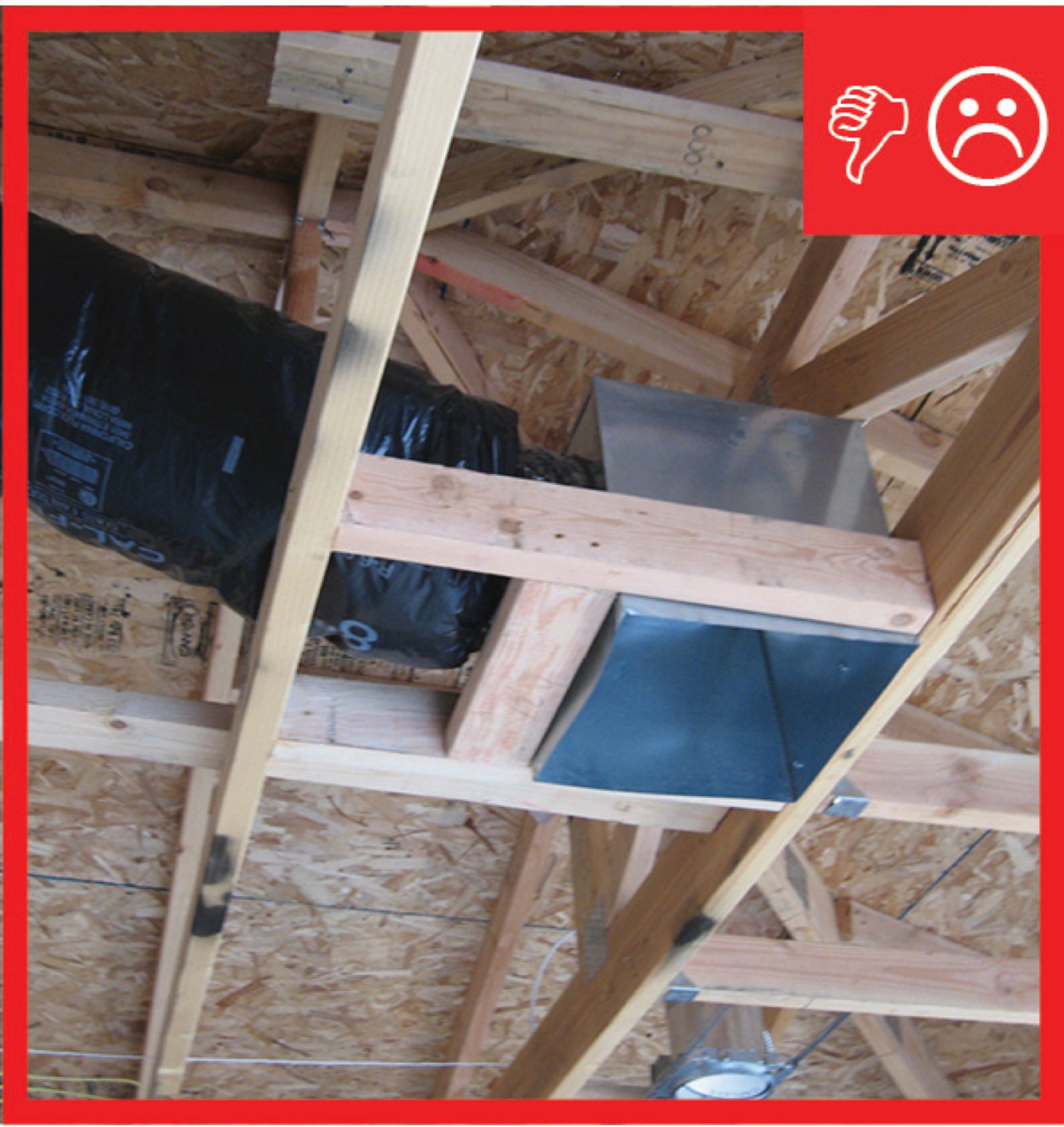
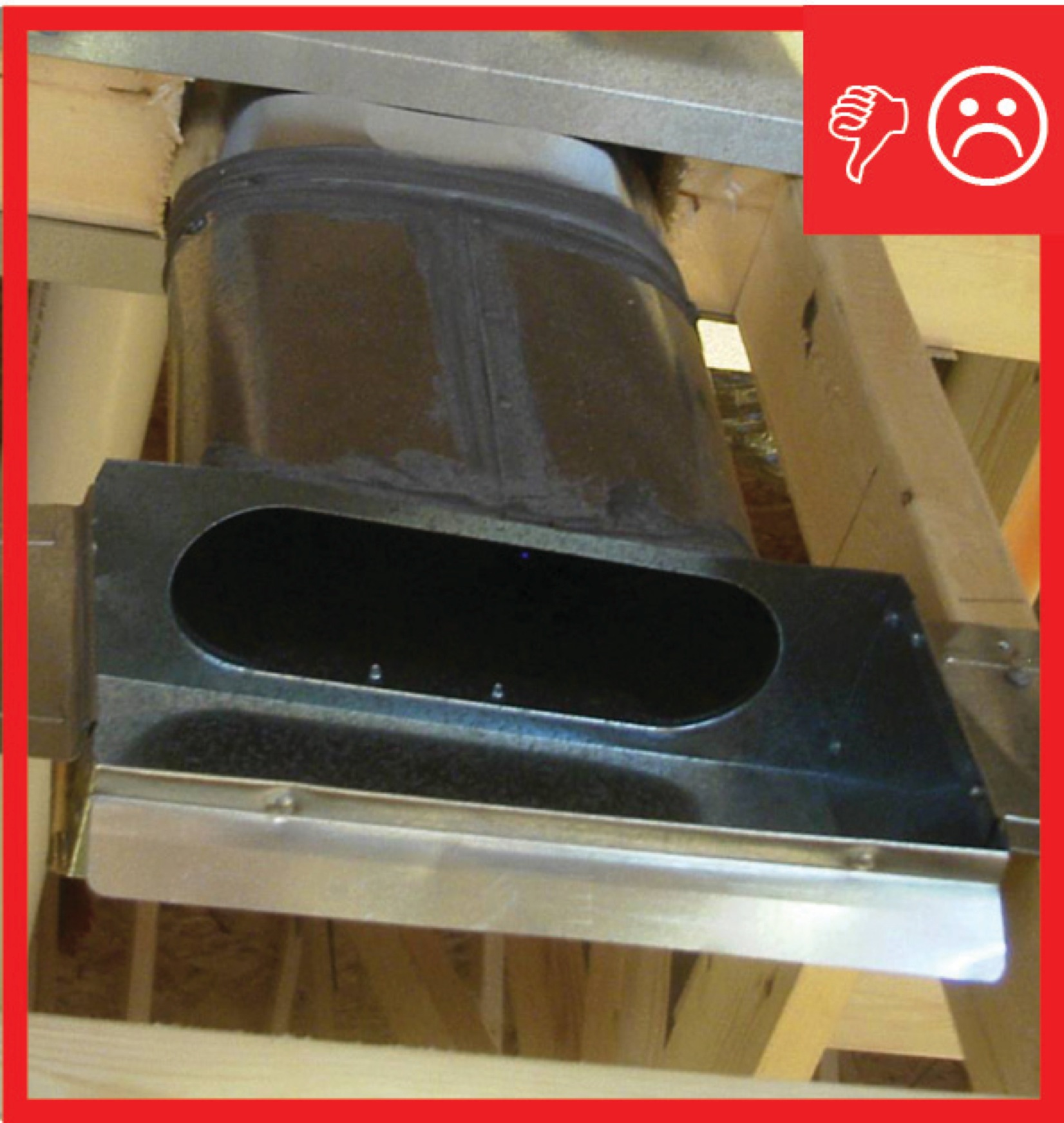
Fans from seperate dwellings exhausted together without back-draft dampers and not sealed
Image
Image
Image
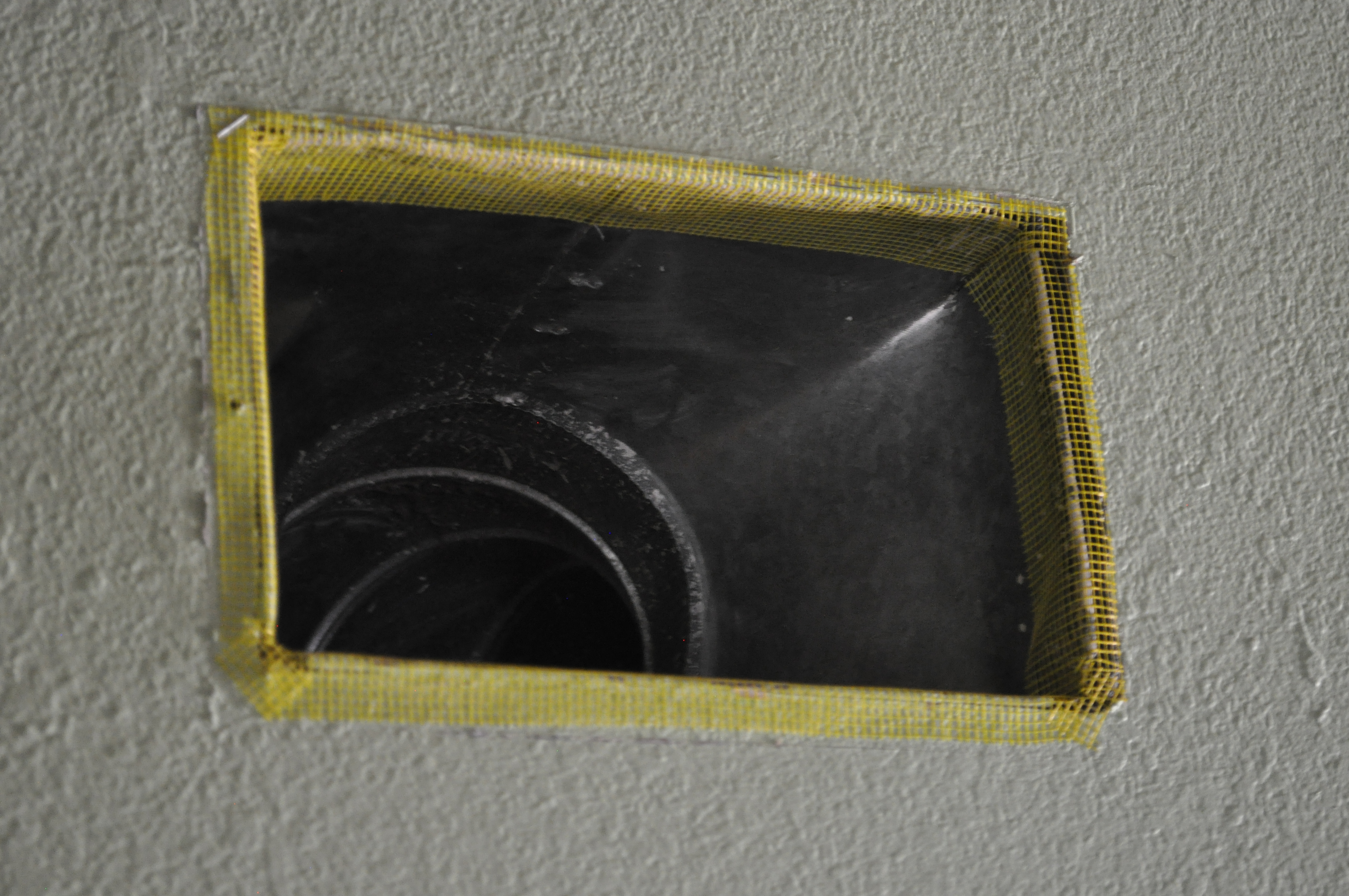
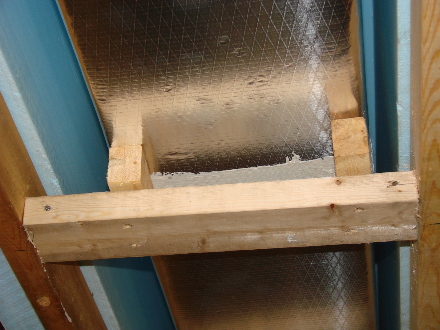
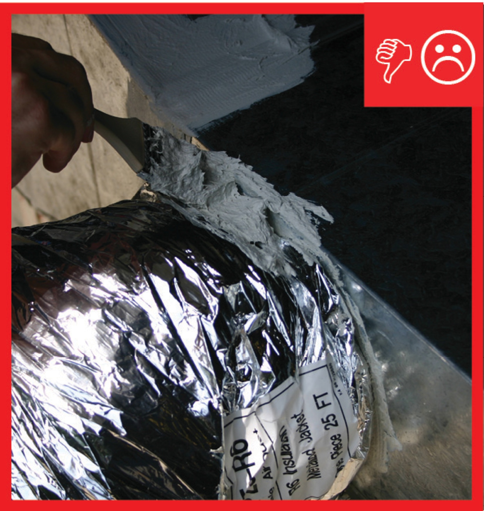
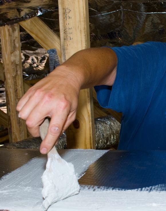
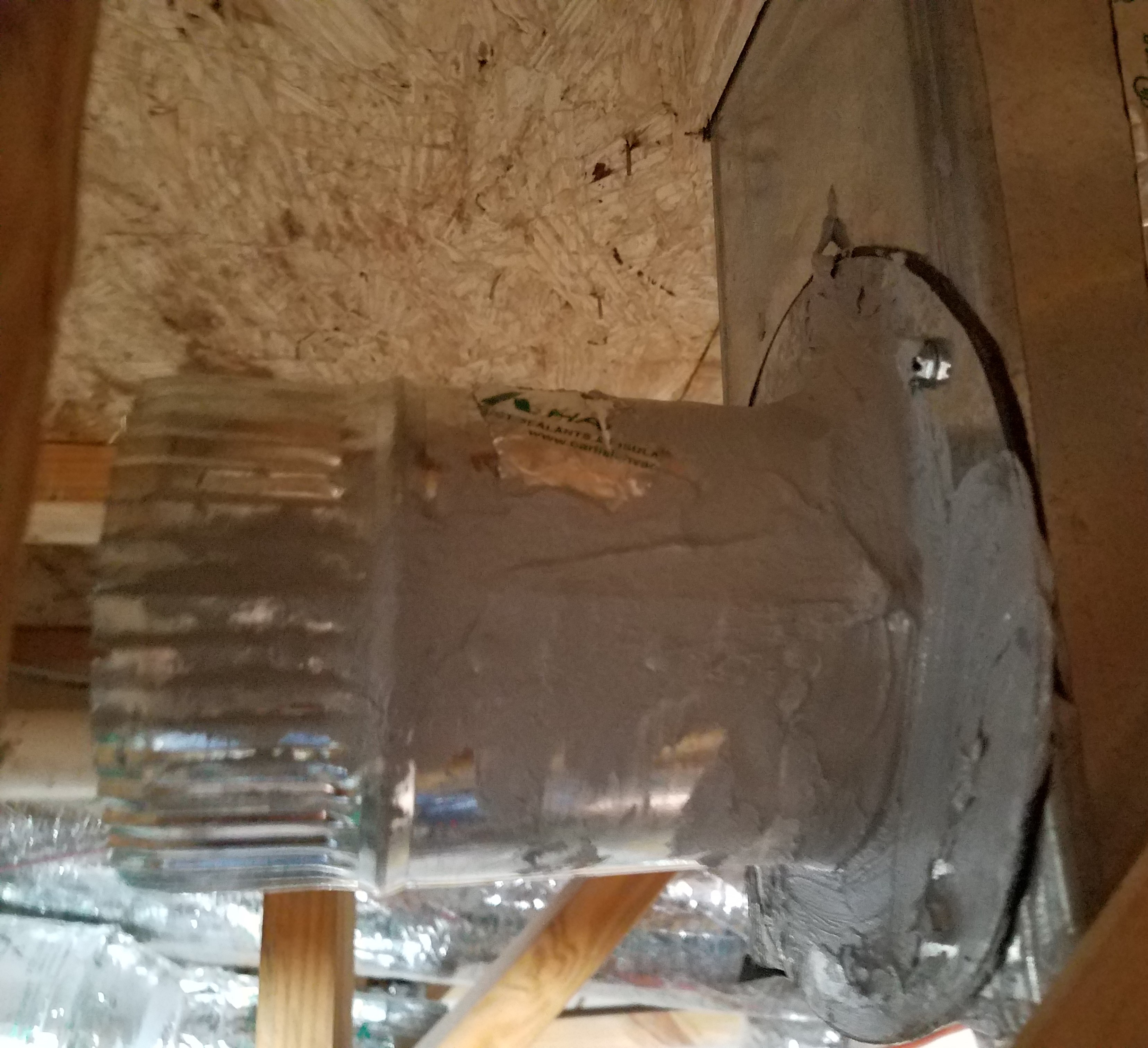
Fiberglass mesh tape is installed around a duct boot in preparation for air sealing with mastic
Image
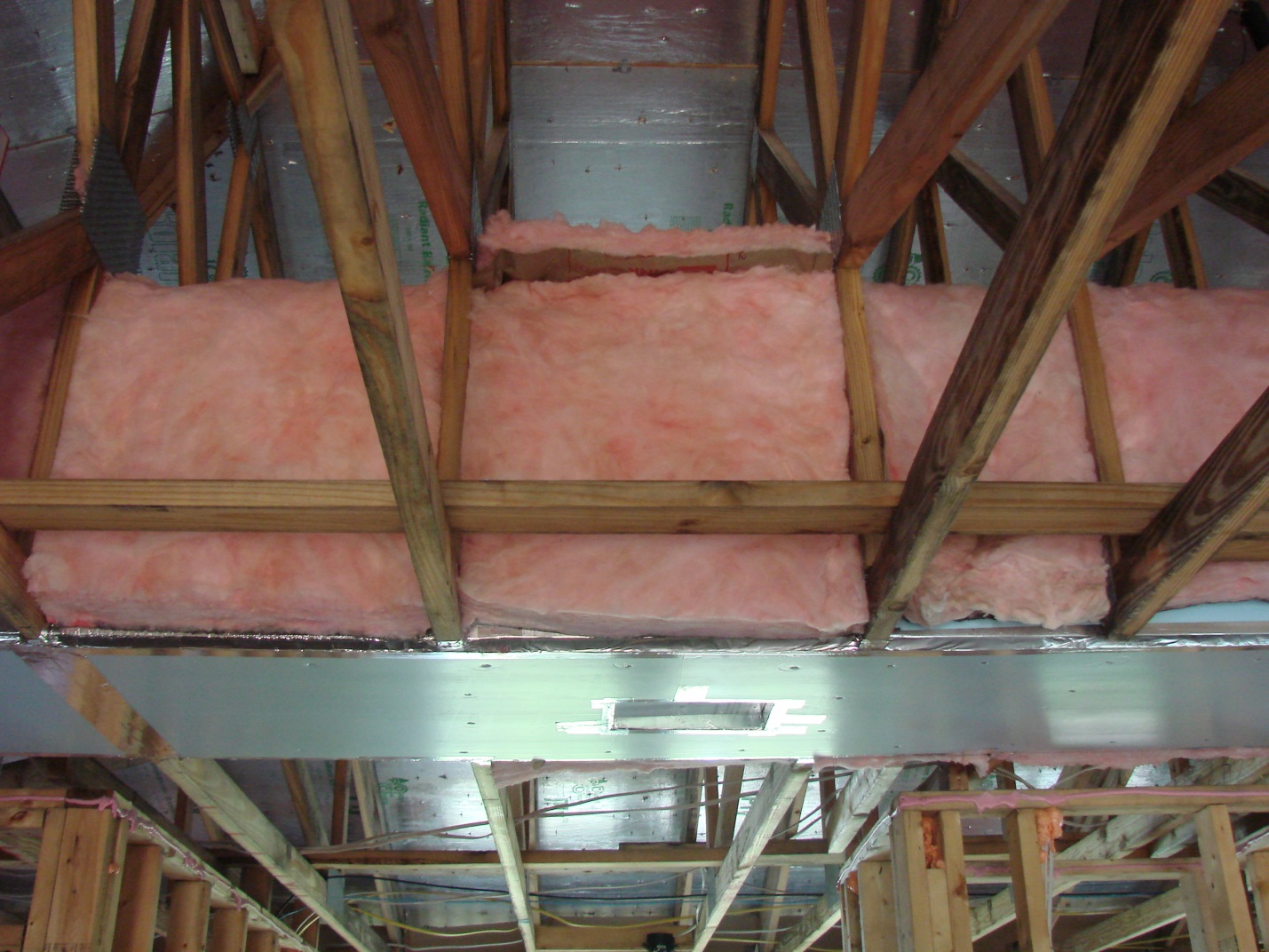
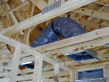
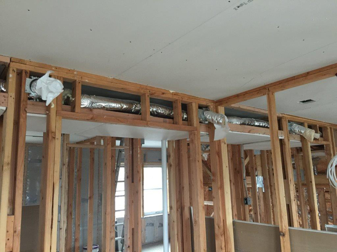
Finished raised ceiling duct chase
Image
Image
Image
Image
Image
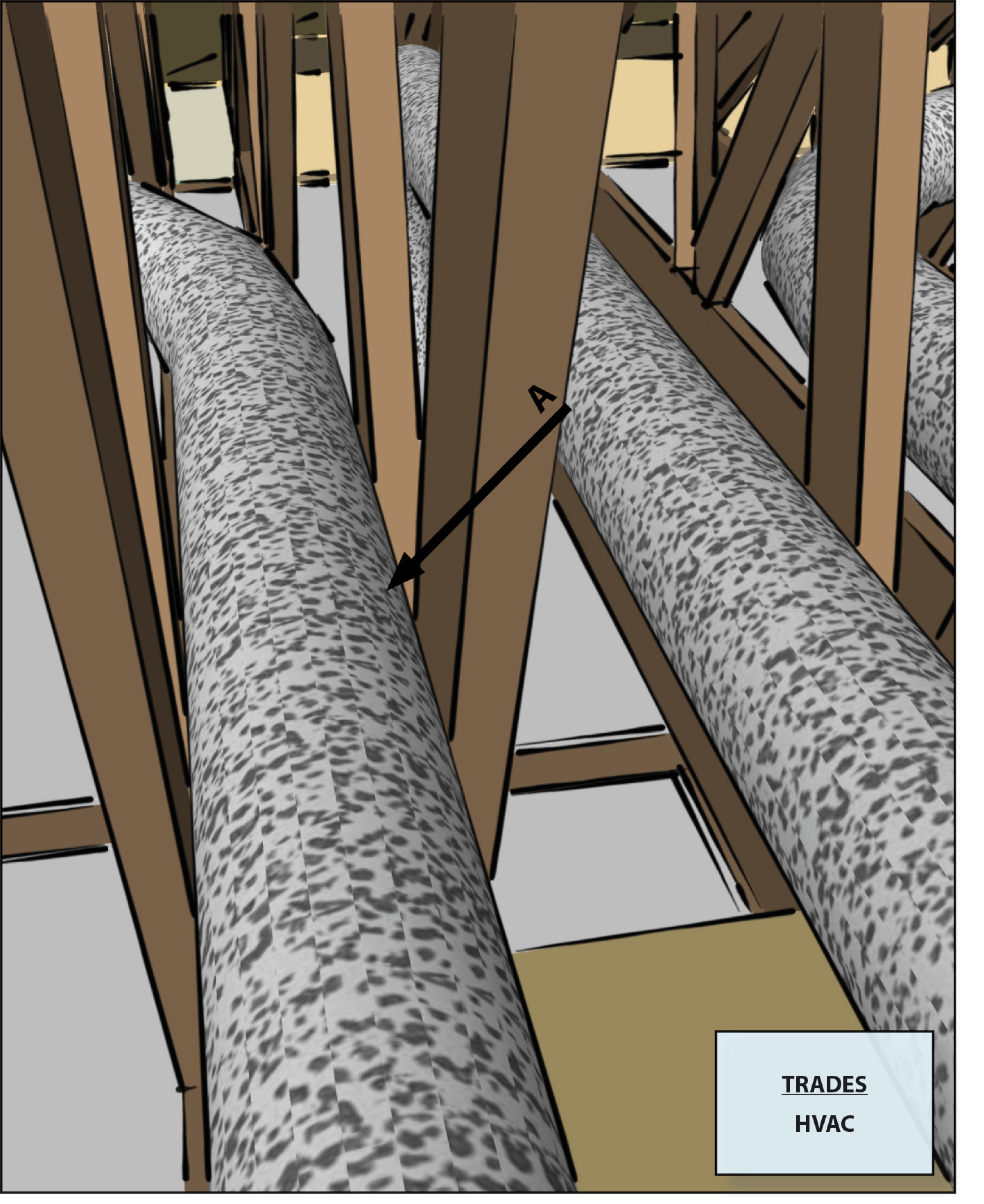
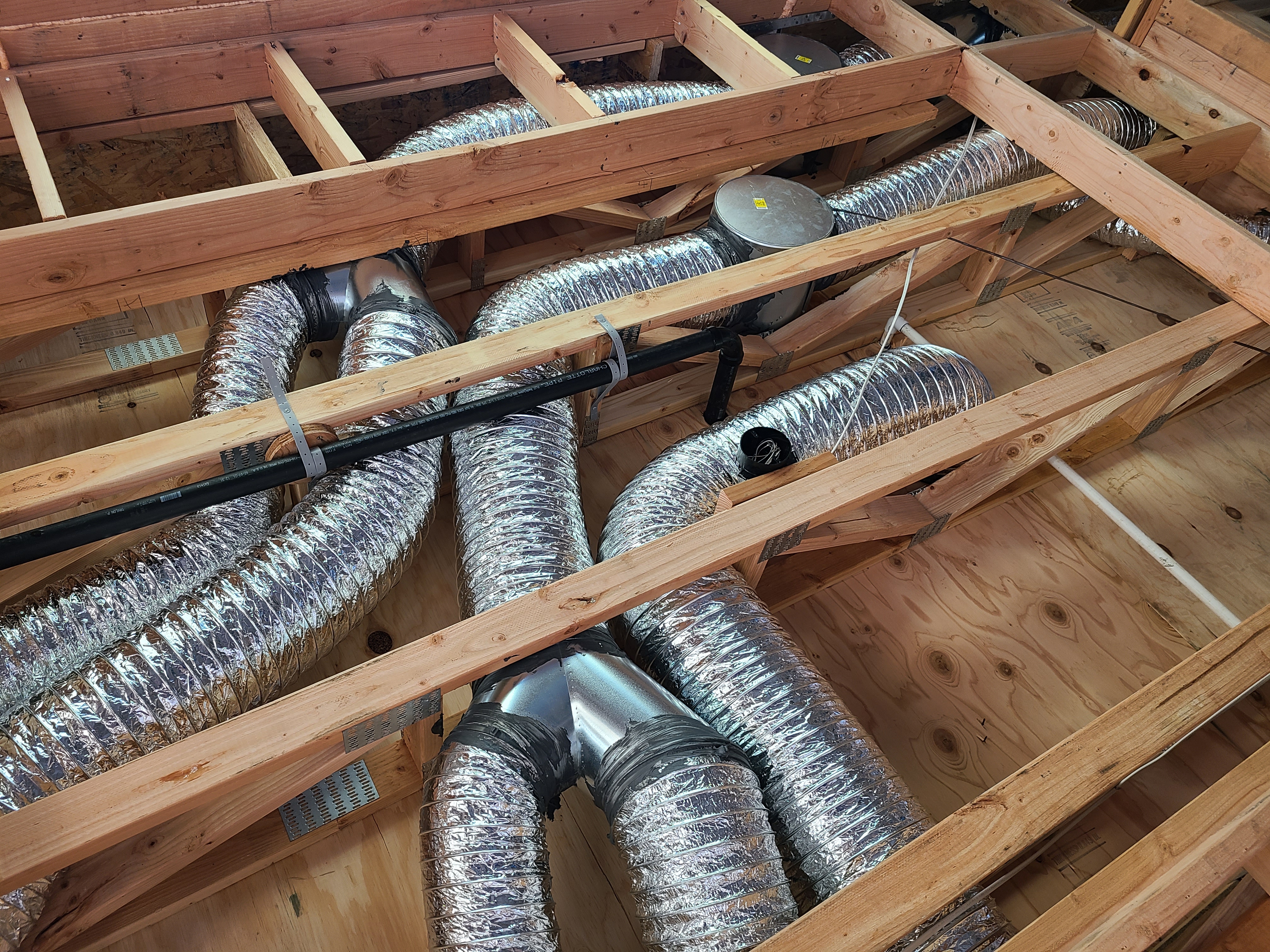
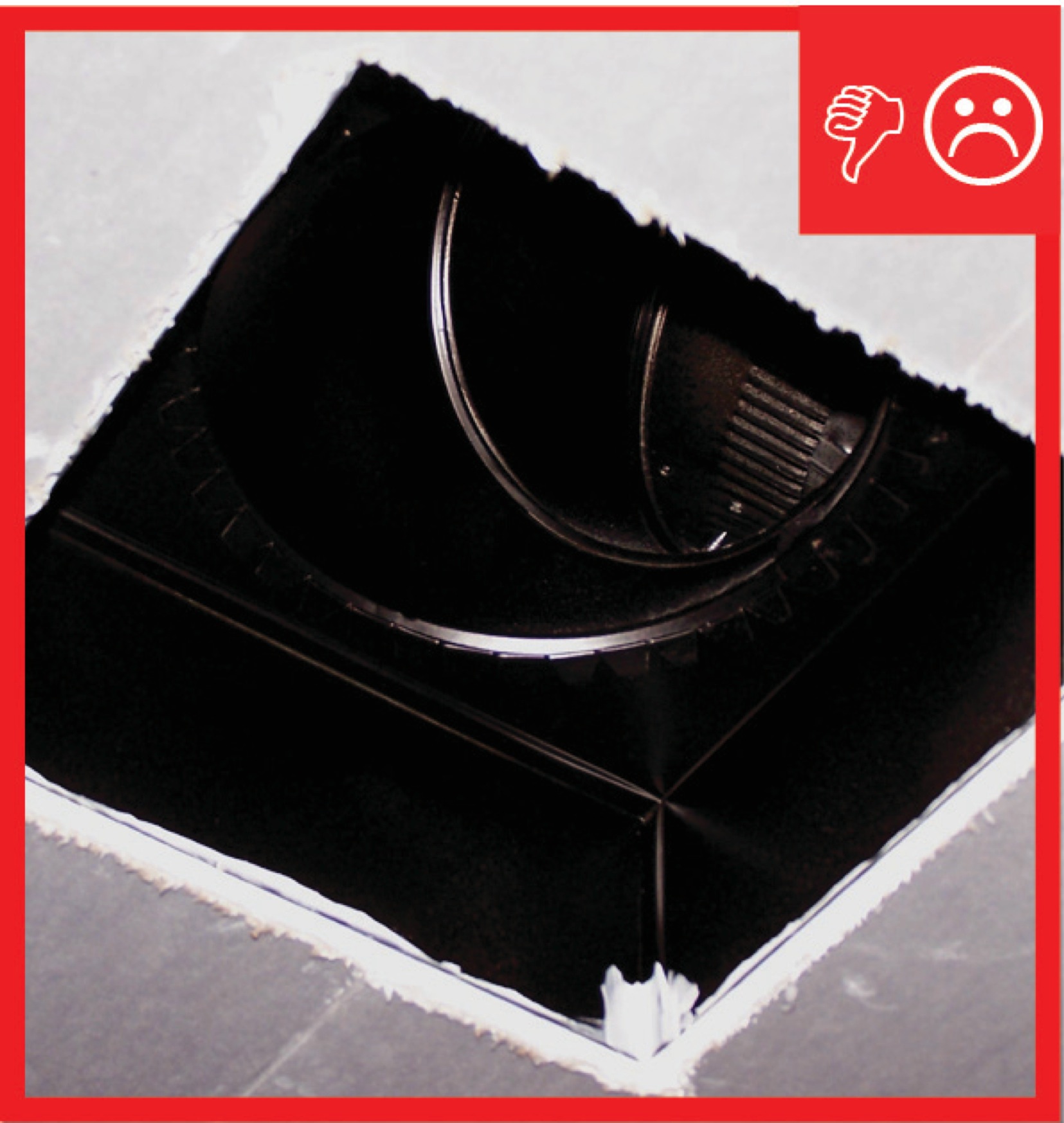
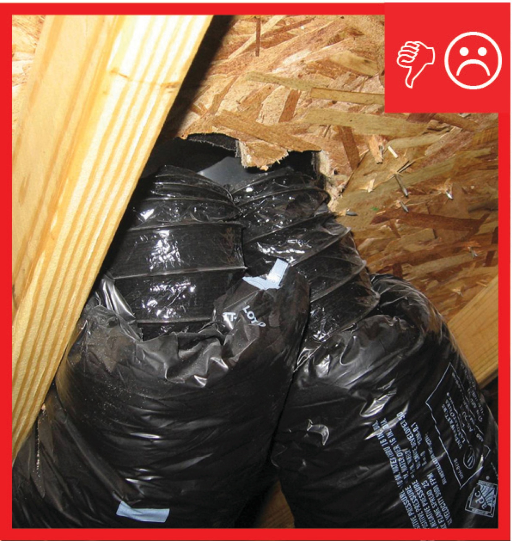
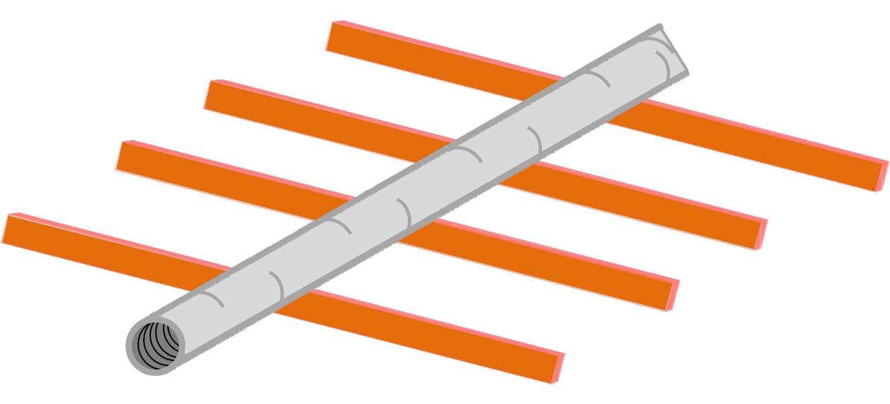
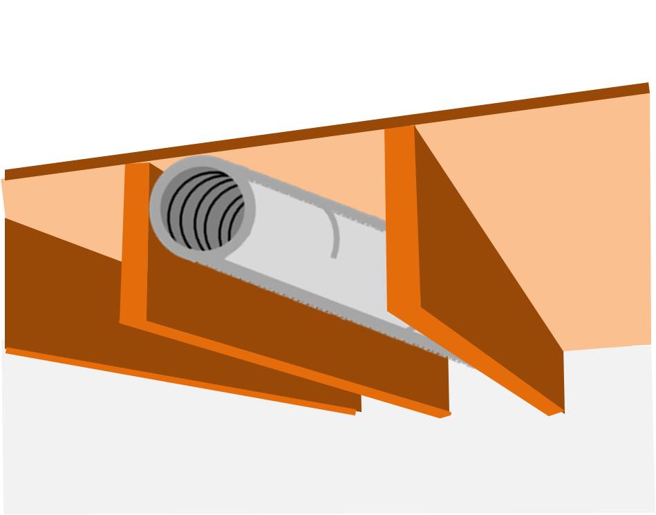
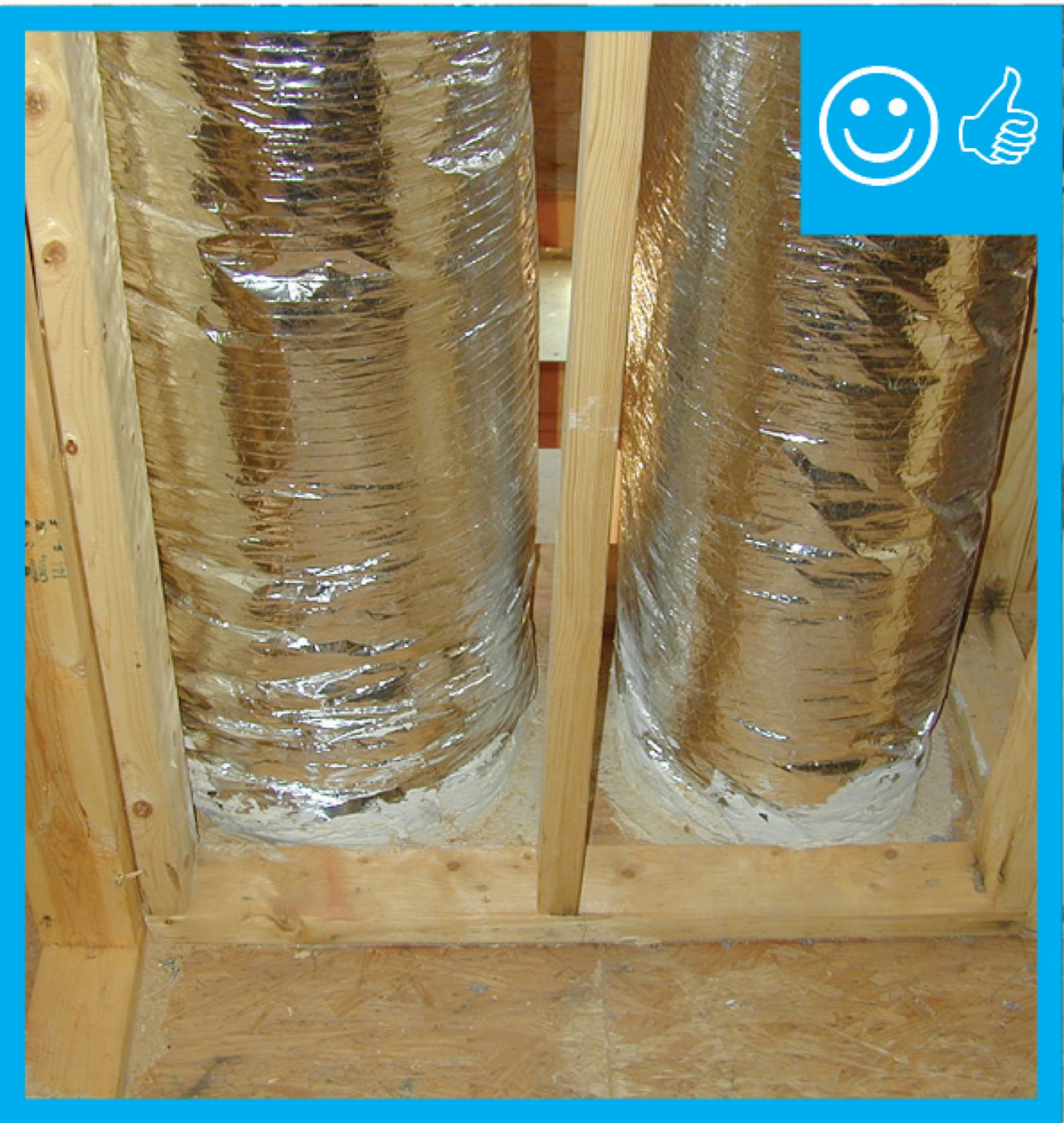
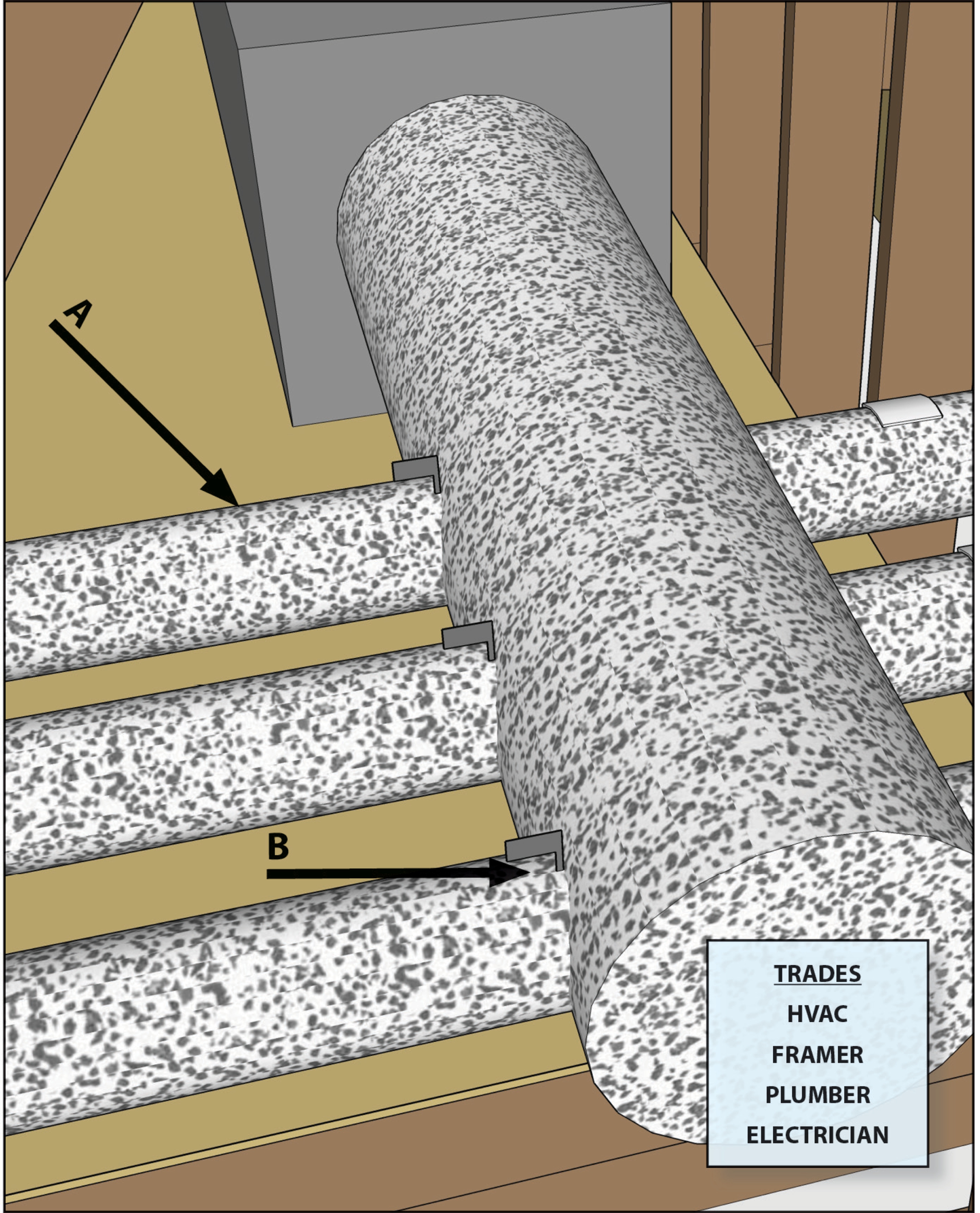
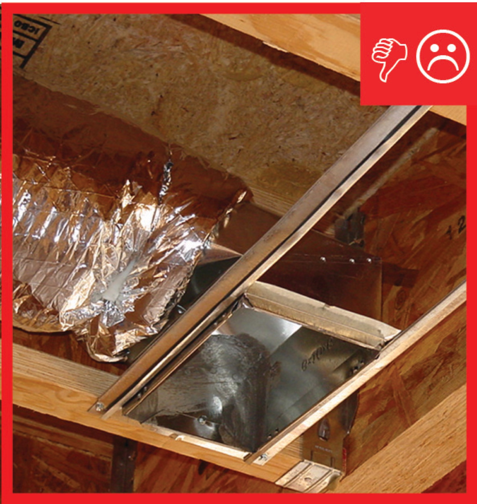
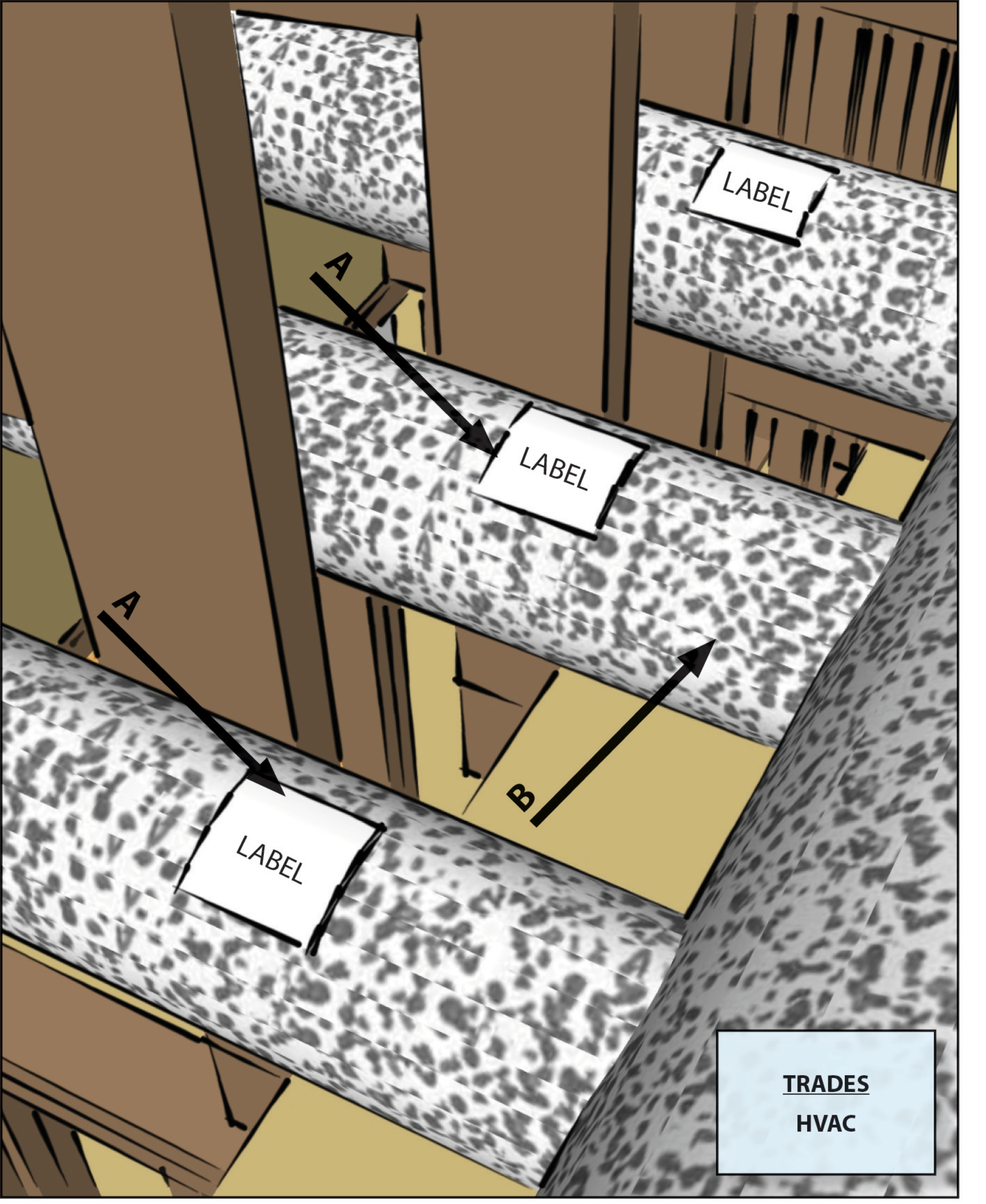
Flexible ducts in unconditioned space not installed in cavities smaller than outer duct diameter; in conditioned space not installed in cavities smaller than inner duct diameter
Image
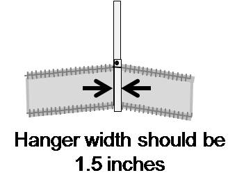
Flexible ducts supported at intervals as recommended by mfr. but at a distance ≤ 5 ft
Image
Image
Image
Image
Image
Image

Fresh air intakes and exhaust vents are ducted to each unit in this multifamily building
Image
Image

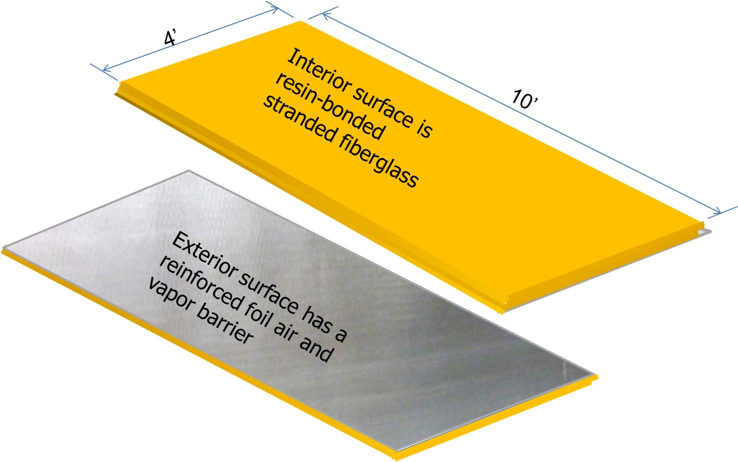
Hand tools for cutting fiber board sheets include a knife, straight edge, and color-coded edge-cutting tools
Image
Image
Image
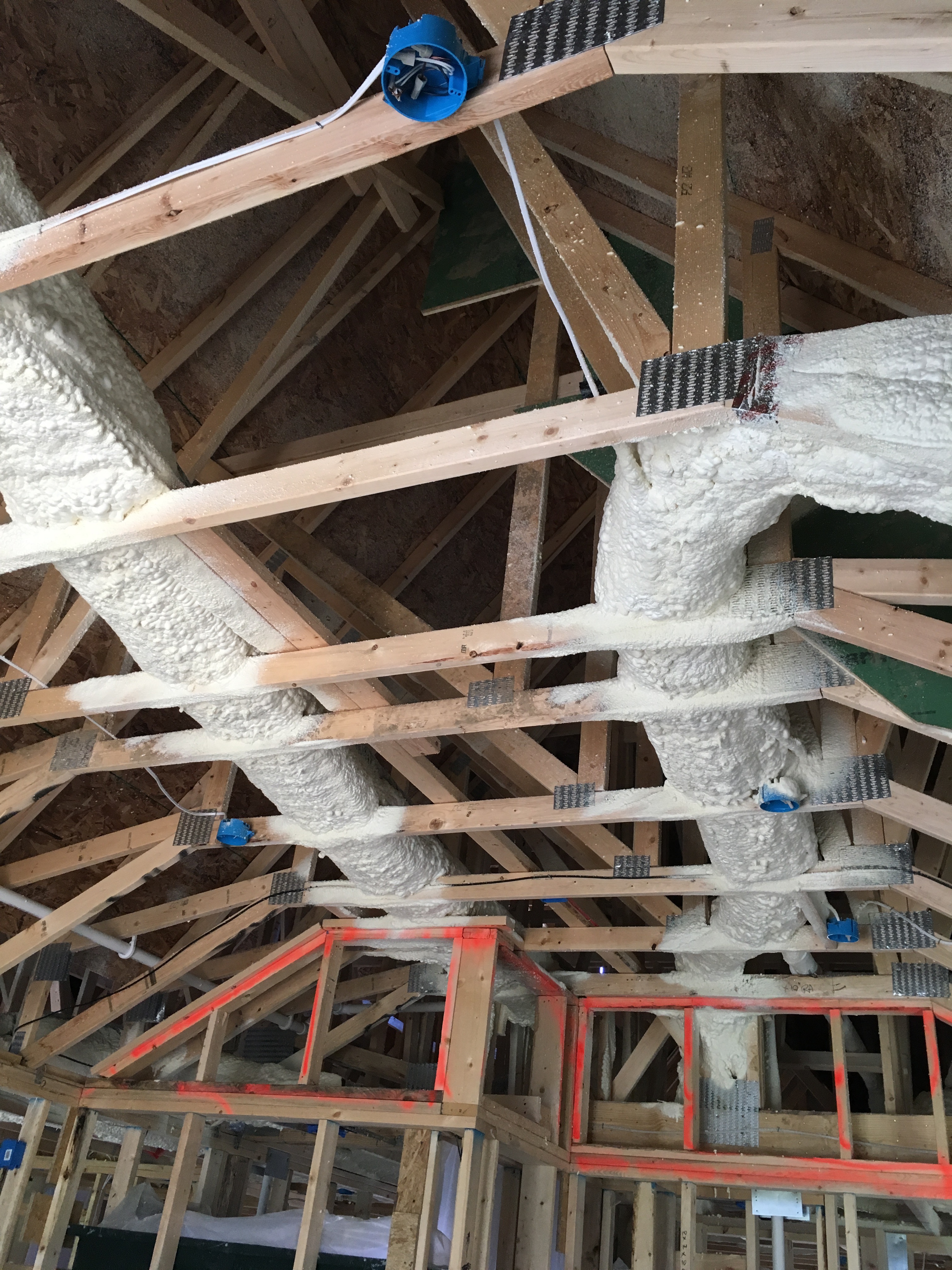
HVAC ducts can be encapsulated in 3 inches of closed-cell spray foam, then buried in R-49 of blown fiberglass insulation after the ceiling drywall is installed in the vented attic.
Image
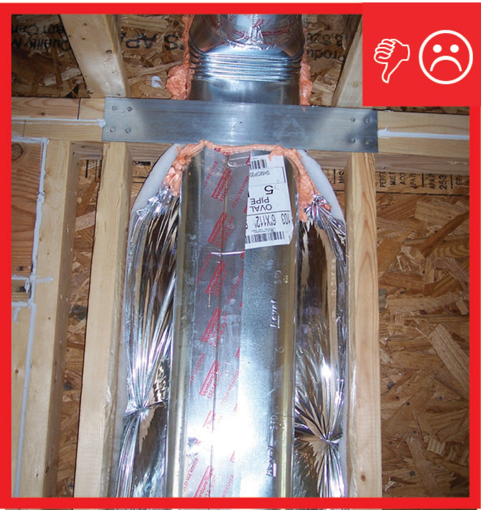
HVAC ducts, cavities used as ducts, and combustion inlets and outlets may pass perpendicularly through exterior walls but shall not be run within exterior walls unless at least R-6 continuous insulation is provided on exterior side of the cavity
Image
If a dropped soffit is used to house a duct, the soffit space must equal the duct diameter plus the insulation thickness
Image

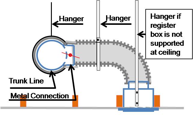
If airflow must be limited to a supply register, use balancing dampers at the trunk line rather than looping duct to control airflow
Image
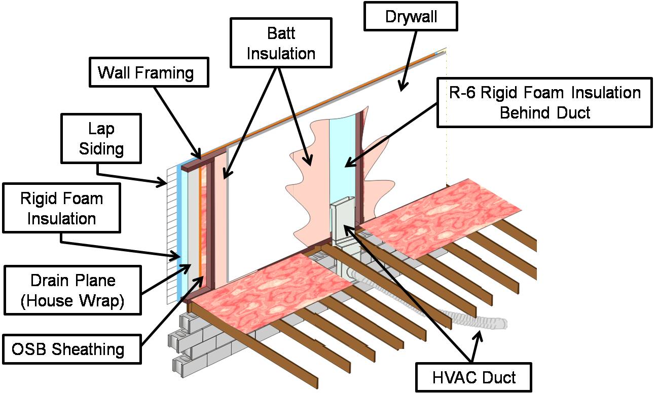
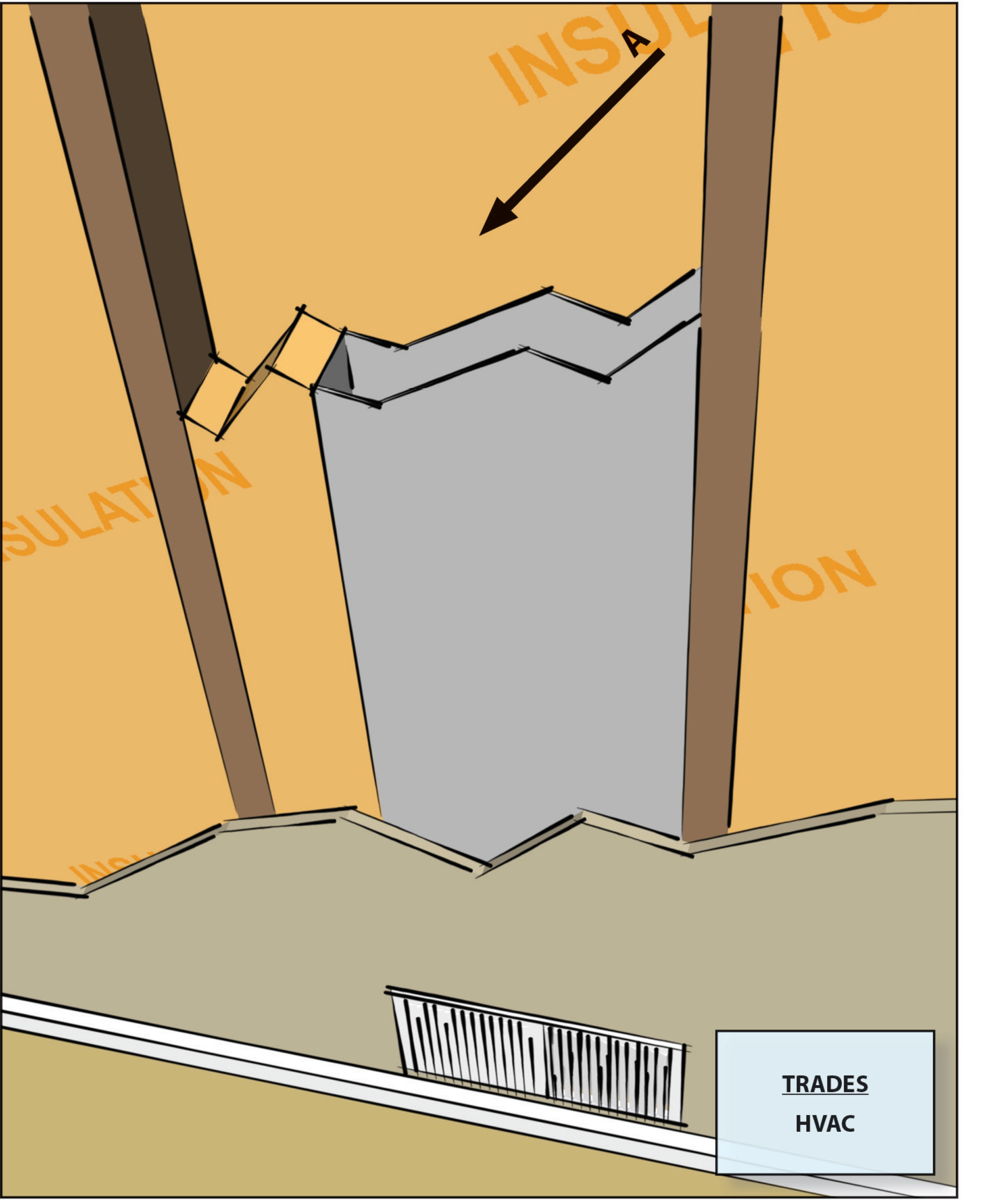
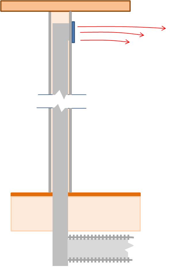
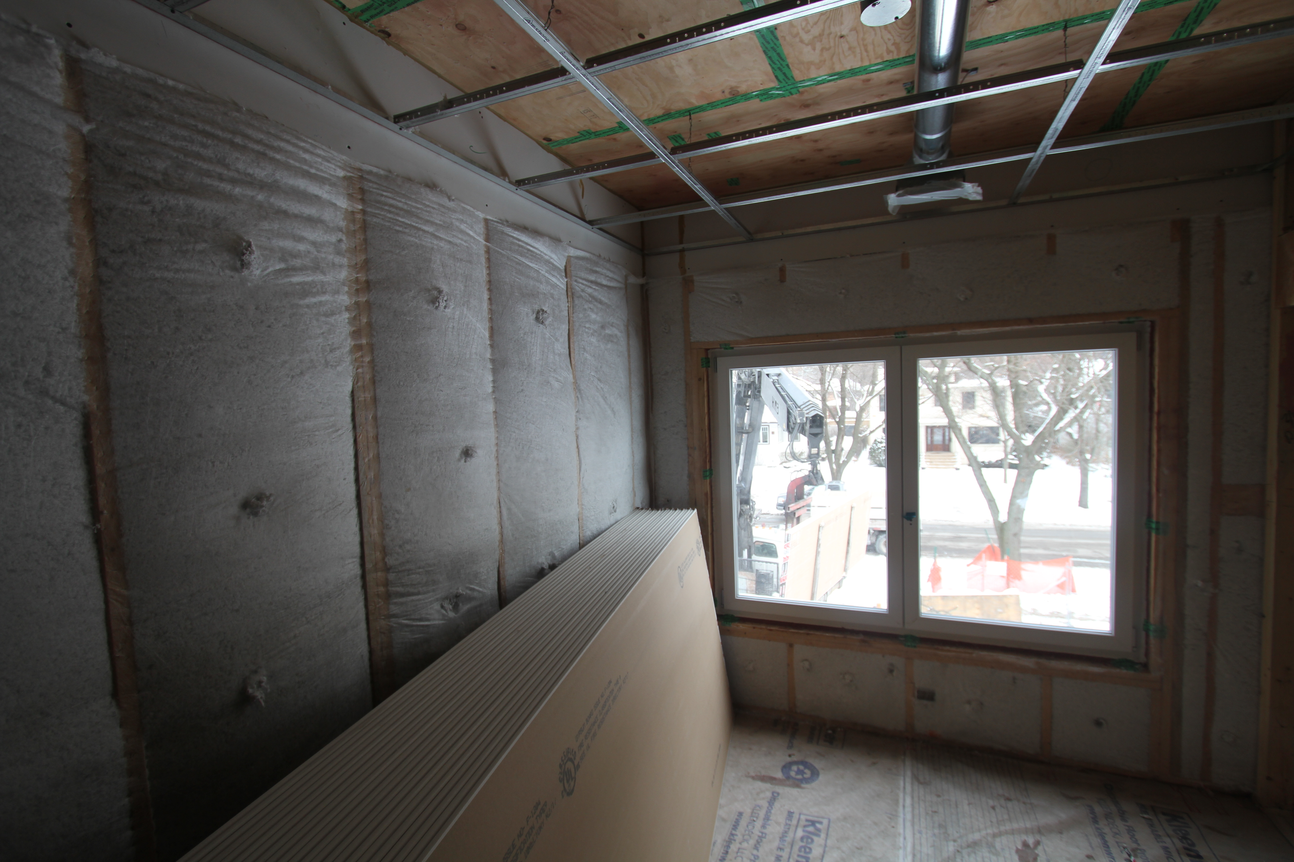
If HVAC duct must be installed in an exterior wall, separate it from the exterior with at least R-6 of continuous rigid insulation
Image
Image
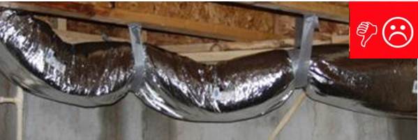
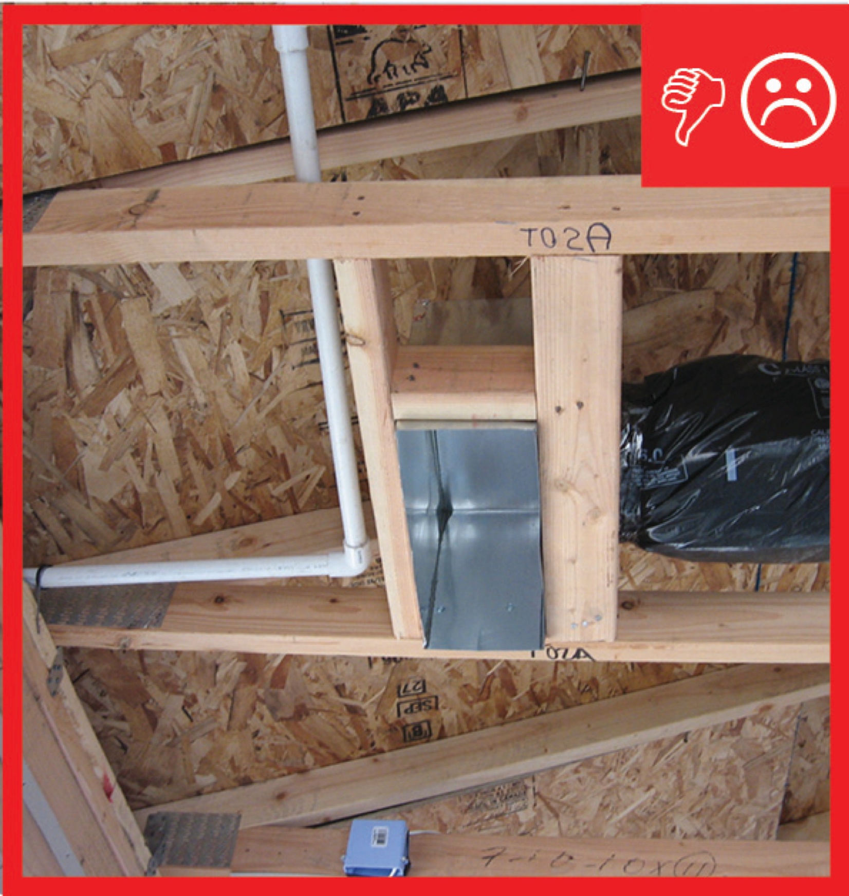
Inadequate amount of insulation installed with compression, misalignment, and voids
Image

Install bottom layer of rigid insulation
Image
Install duct supports in line with ceiling trusses
Image
Image
Image
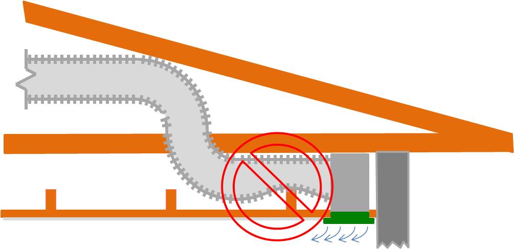
Install supply registers in floors or ceilings to avoid routing ducts through exterior walls
Image
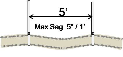
Install supports every 5 feet so that maximum allowable sag in flexible duct is no more than one-half inch per foot
Image
Install supports every 5 feet so that maximum allowable sag in flexible duct is no more than one-half inch per foot
Image
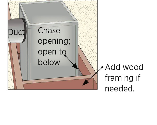
Install wood framing cross pieces in the attic rafter bays on each side of the duct chase
Image

Image
Image
Image
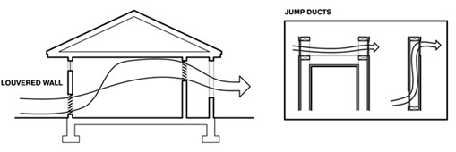
Jump ducts are installed in the ceiling to connect closed rooms with open space to provide a return air path and balance air pressure
Image

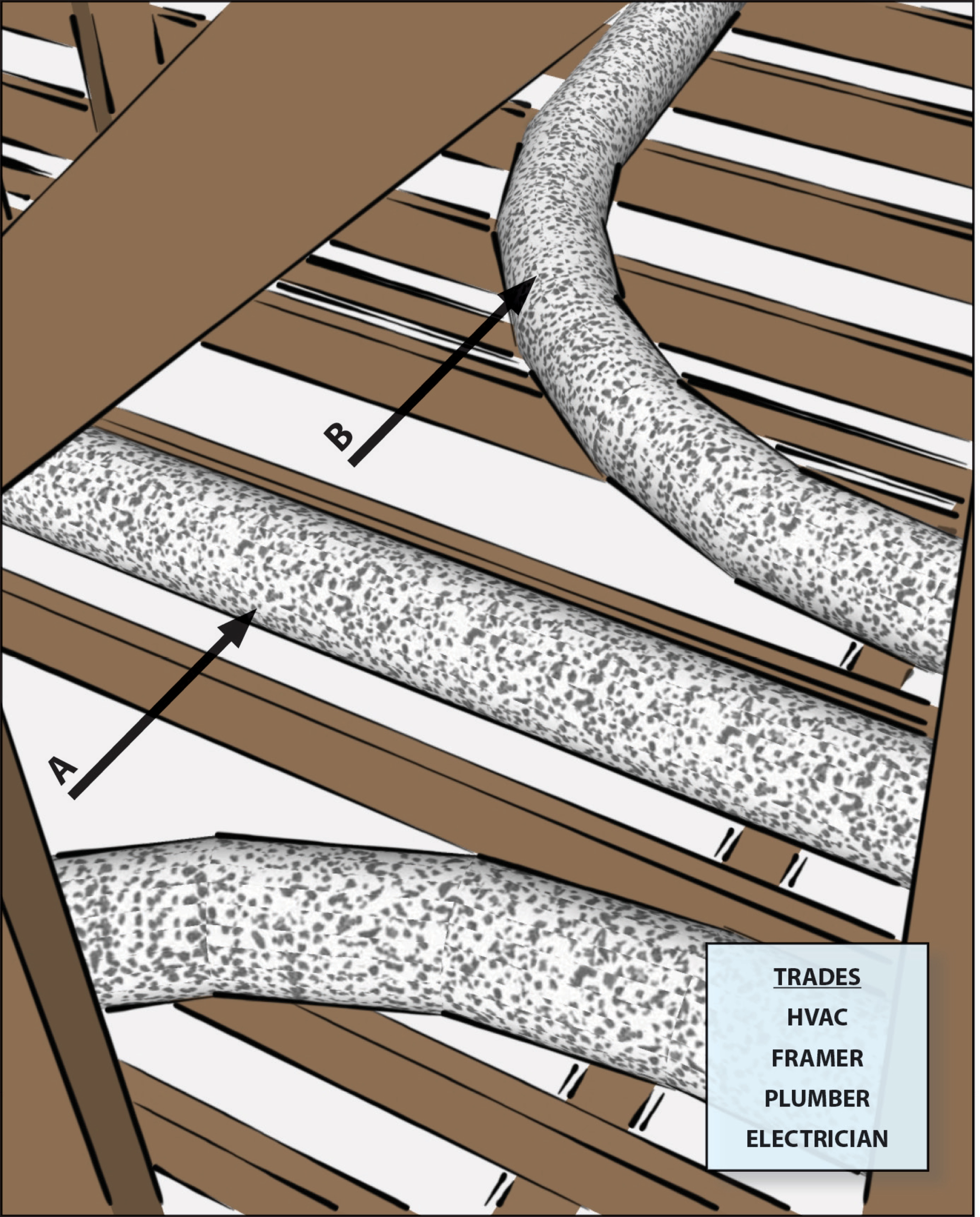
Lay out duct so that no radius of a bend or turn is less than the diameter of the airway
Image
Image
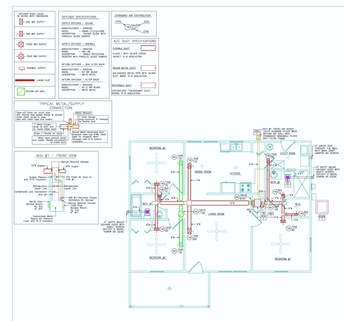
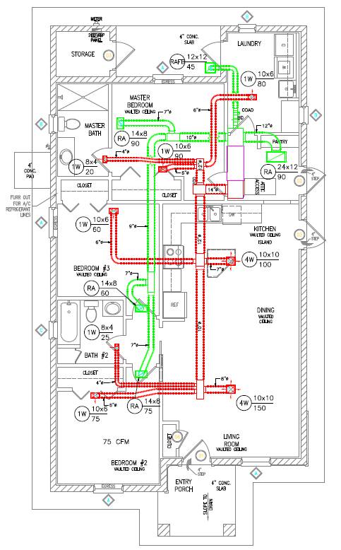
Manual D details show duct size and chase path
Image
Image
Image
Image
Image
Image
Image
Image
Image
Image
Image
Image
Image
Open floor trusses used as return air plenums can draw air from any place connected to that floor
Image
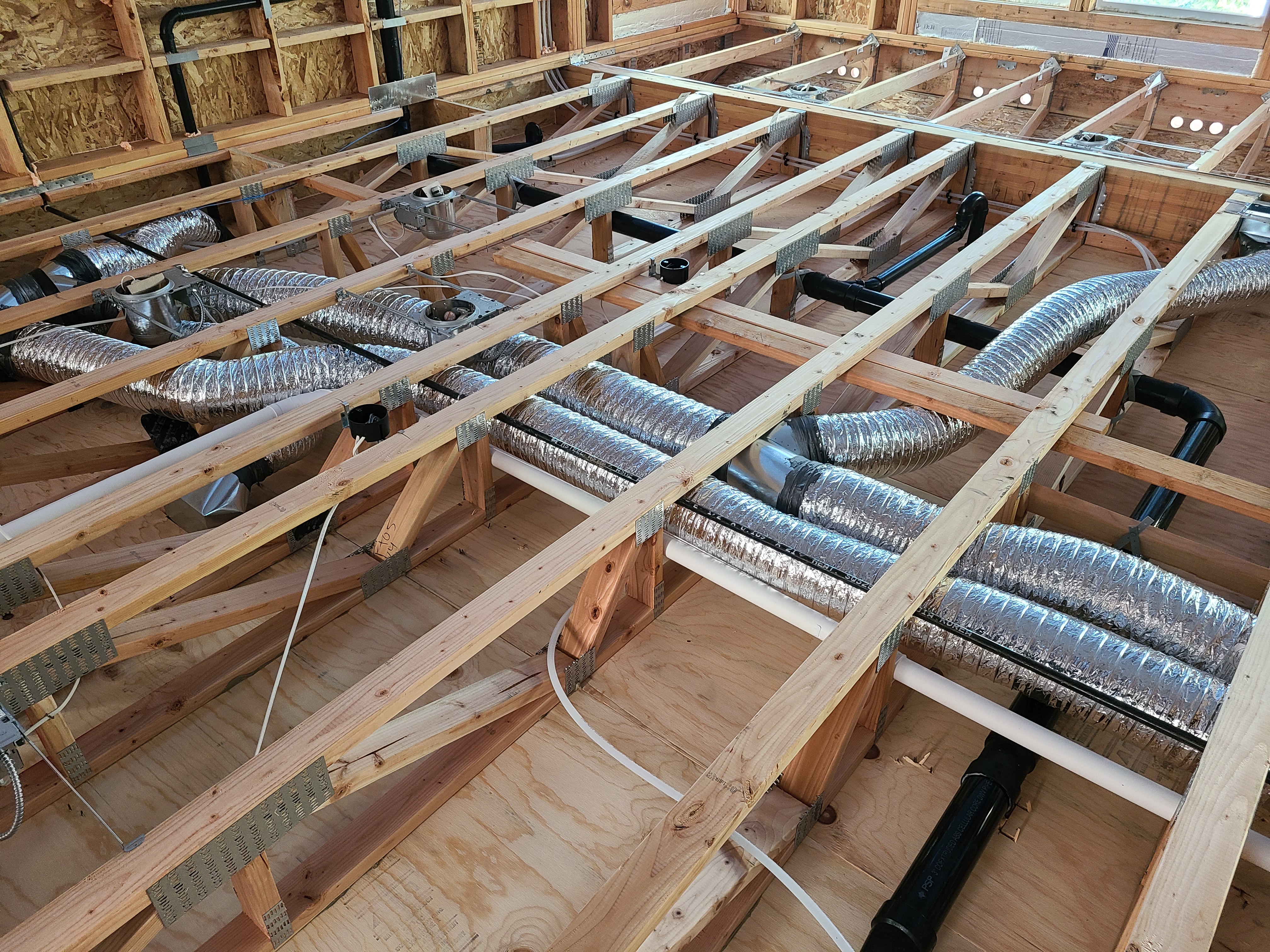
Open-web floor joists provide space for ducts between the floors of a two-story home.
Image
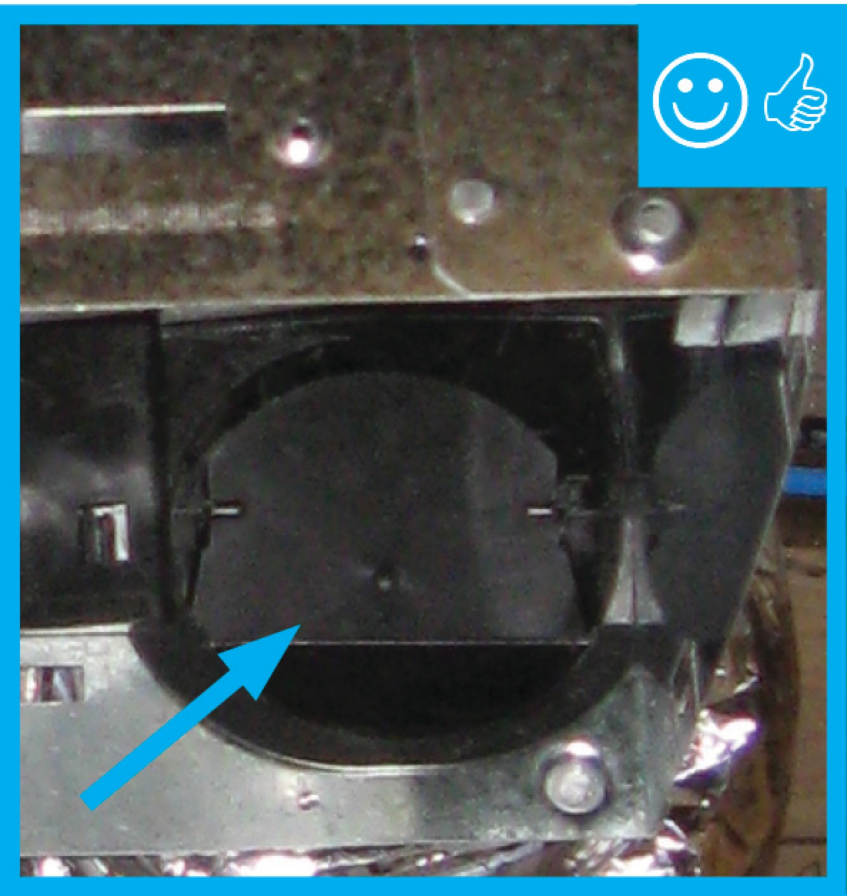
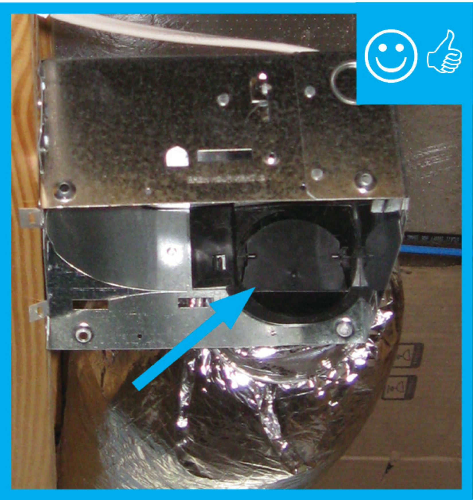
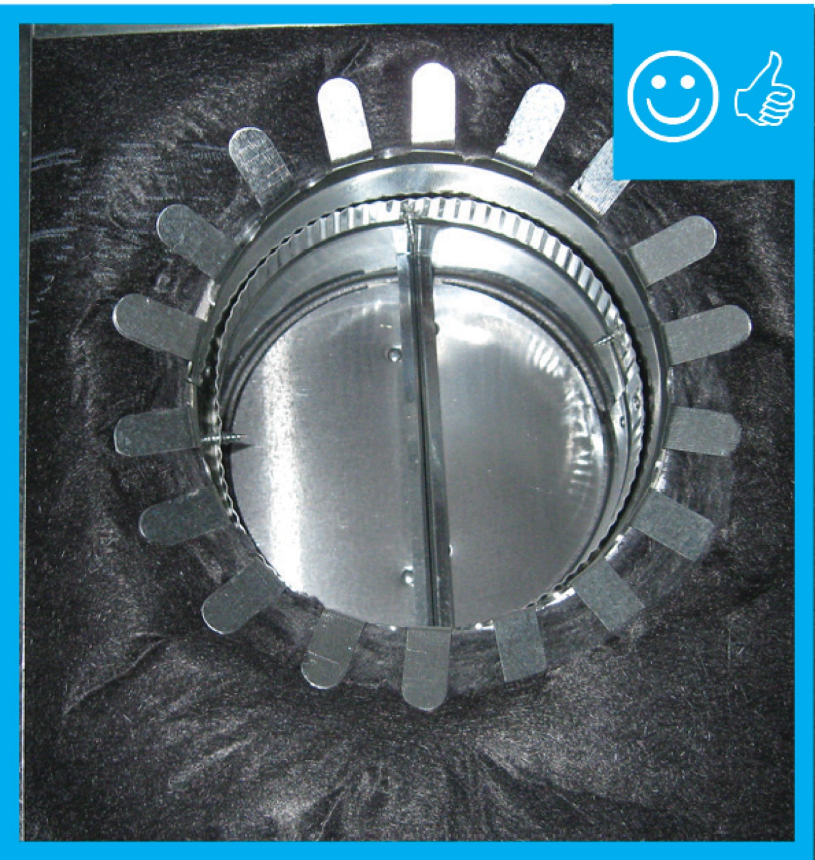
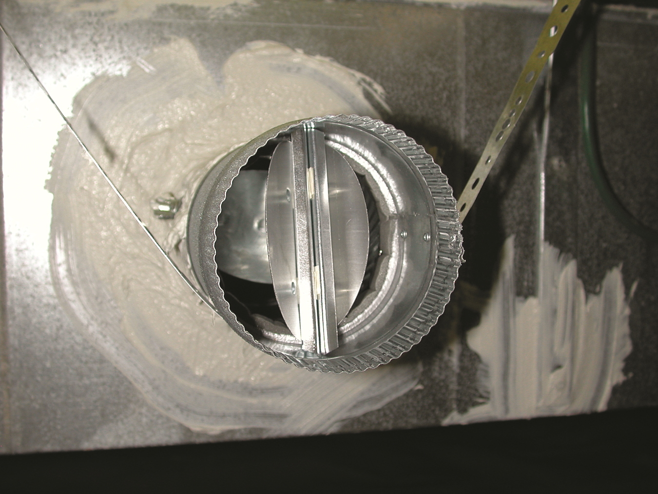
Packing tape has been removed and damper will be able to function properly once fan is installed
Image
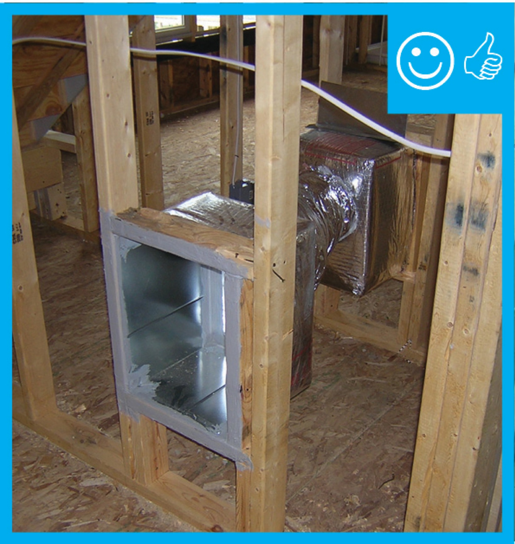
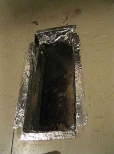
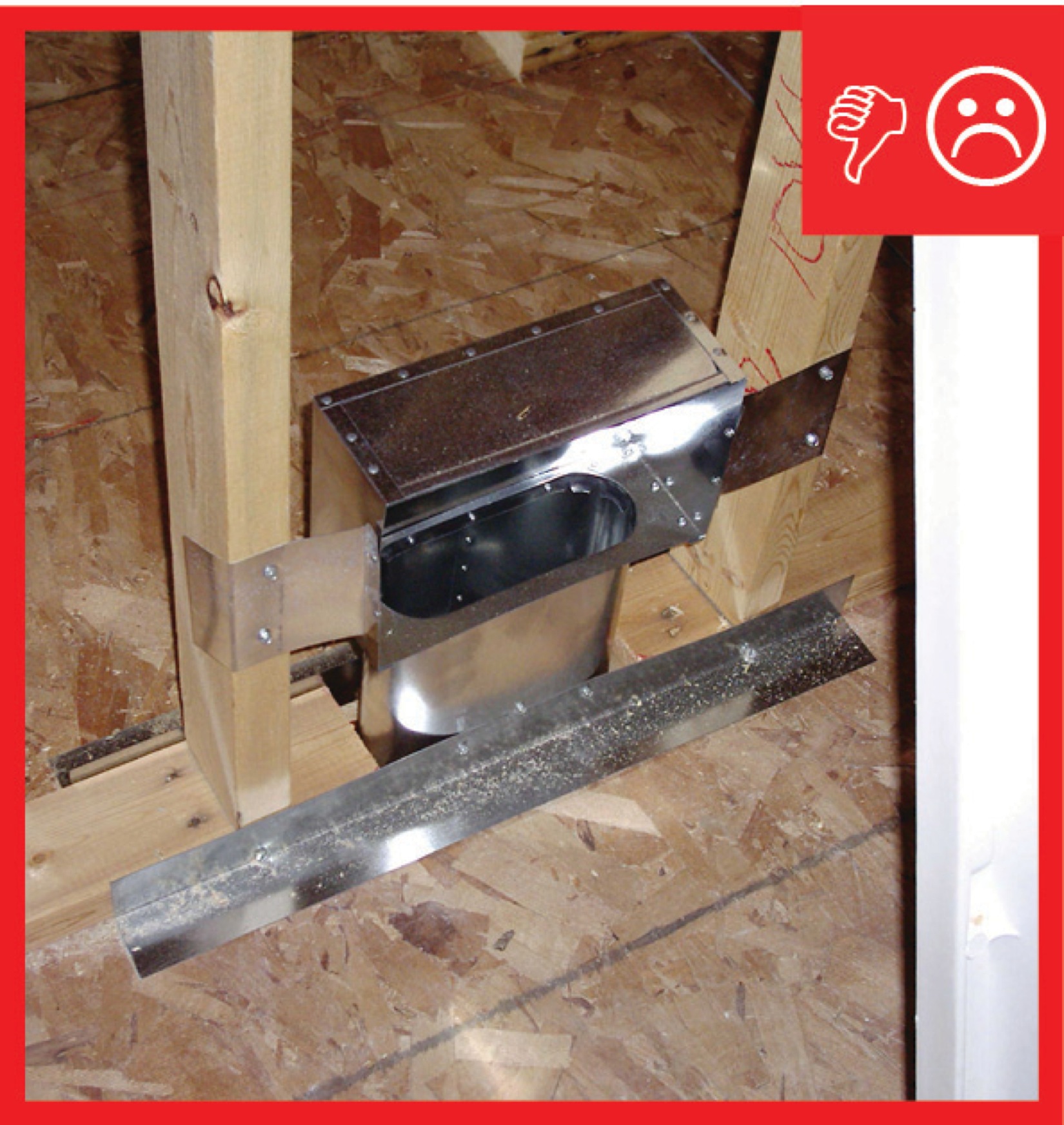
Pan stock is used to form a boot for future register installation
Image
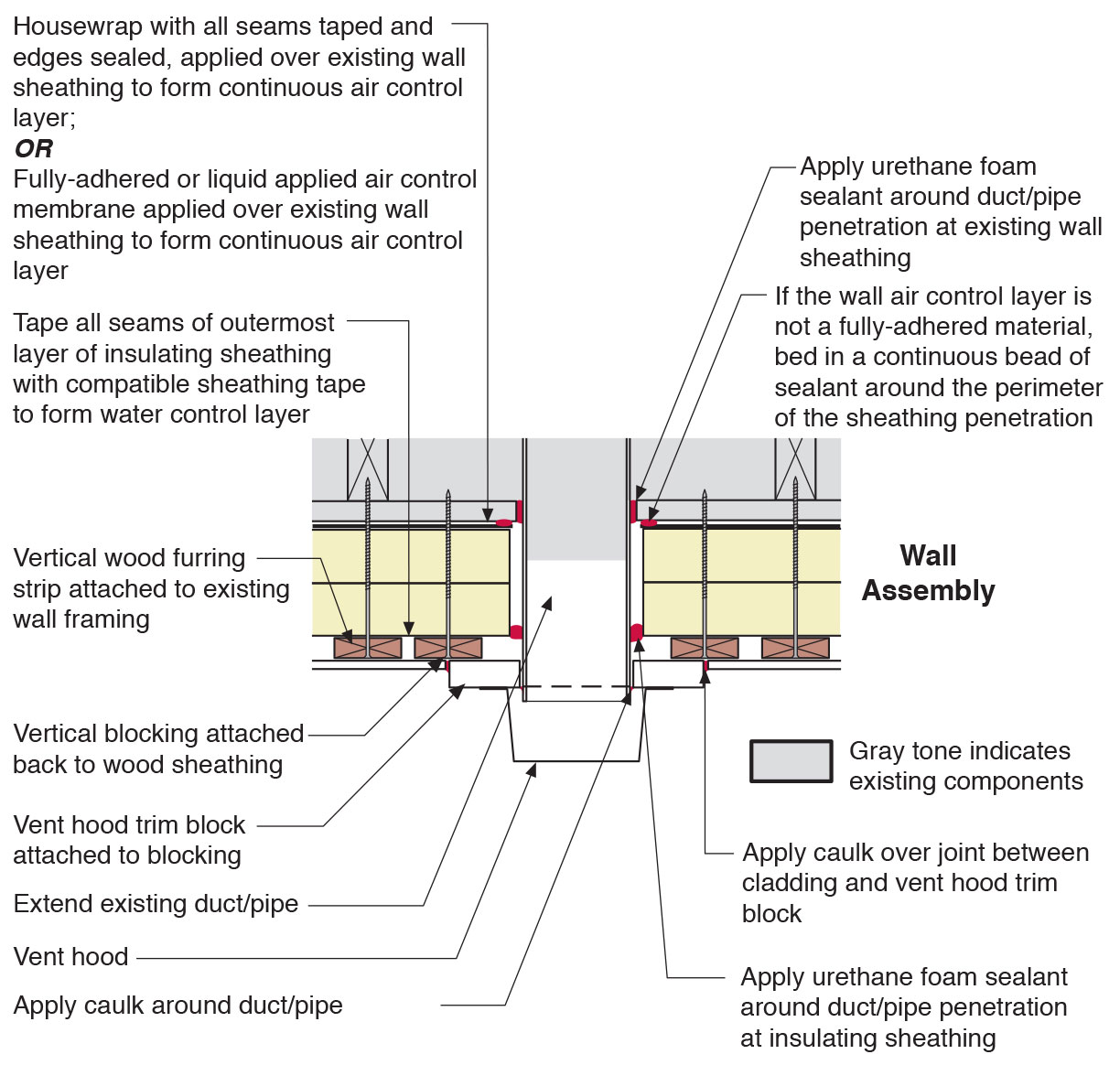
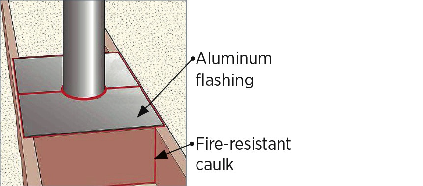
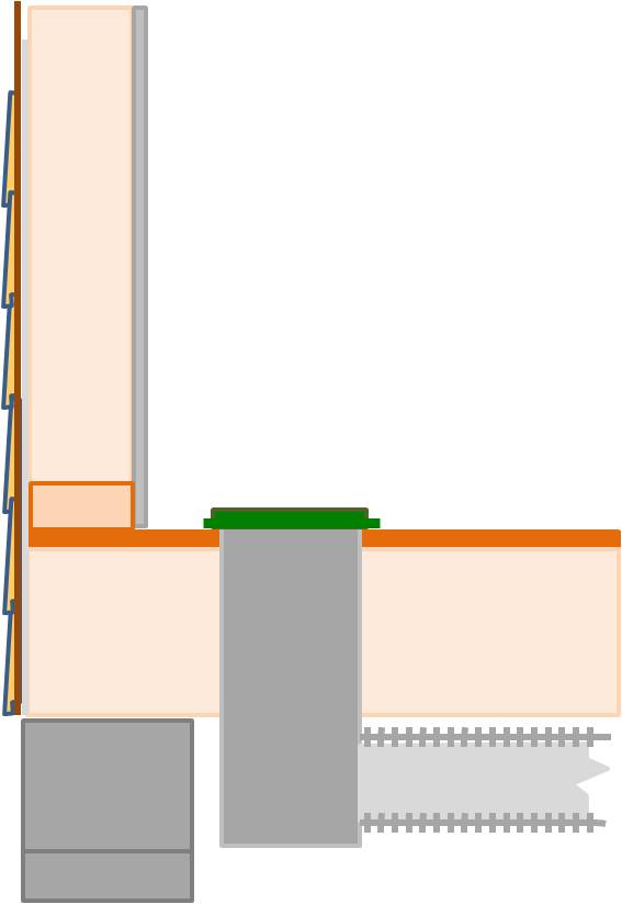
Plan view of duct or pipe penetration through exterior wall showing flashing and air sealing details
Image

Prepare chase with adhesive for bottom insulation
Image
Prescriptive Path: Supply ducts in unconditioned attic have insulation ≥ R-8. Performance Path: Supply ducts in unconditioned attic have insulation ≥ R-6
Image
Image
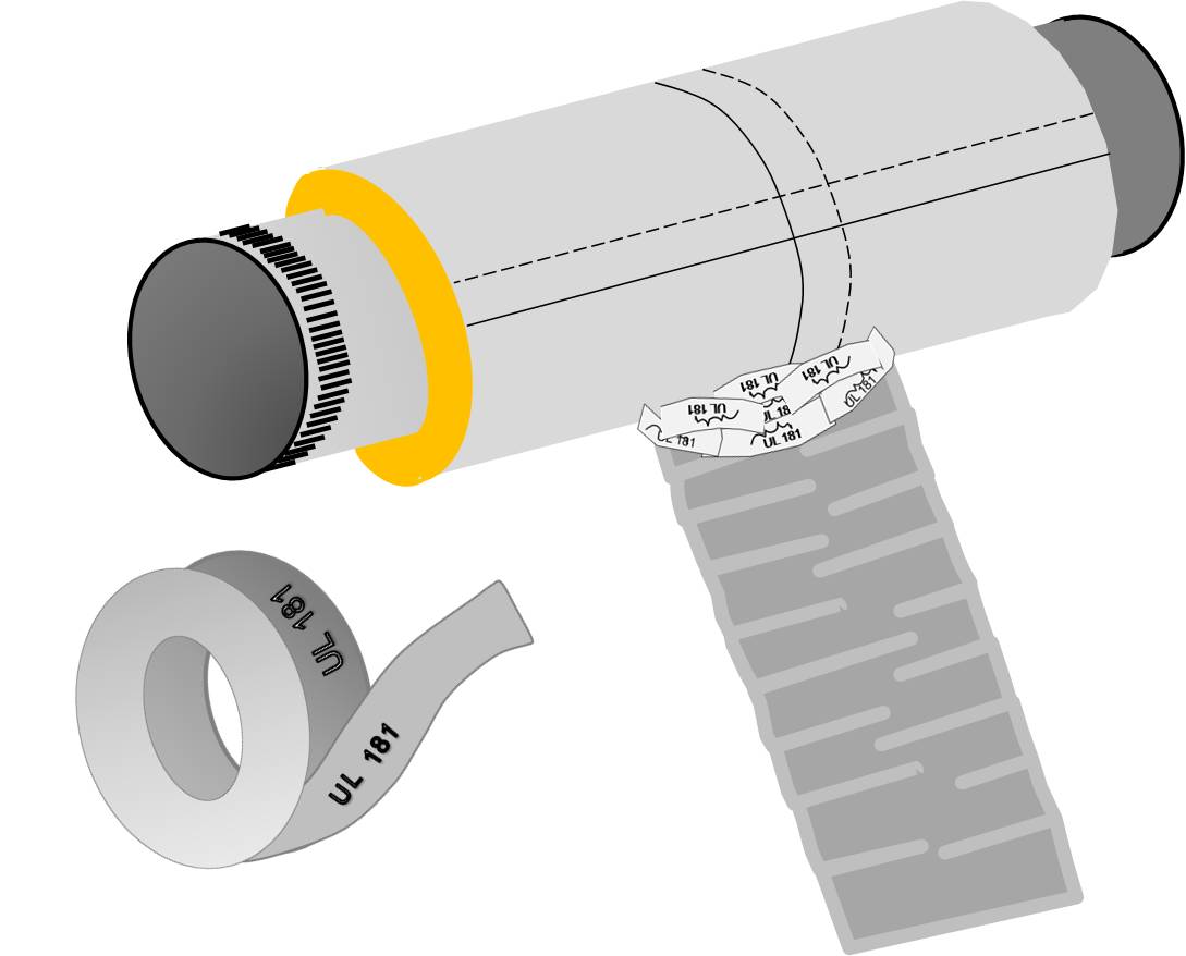
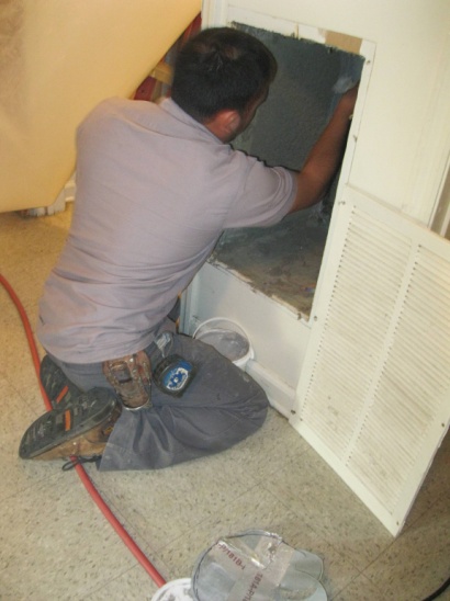
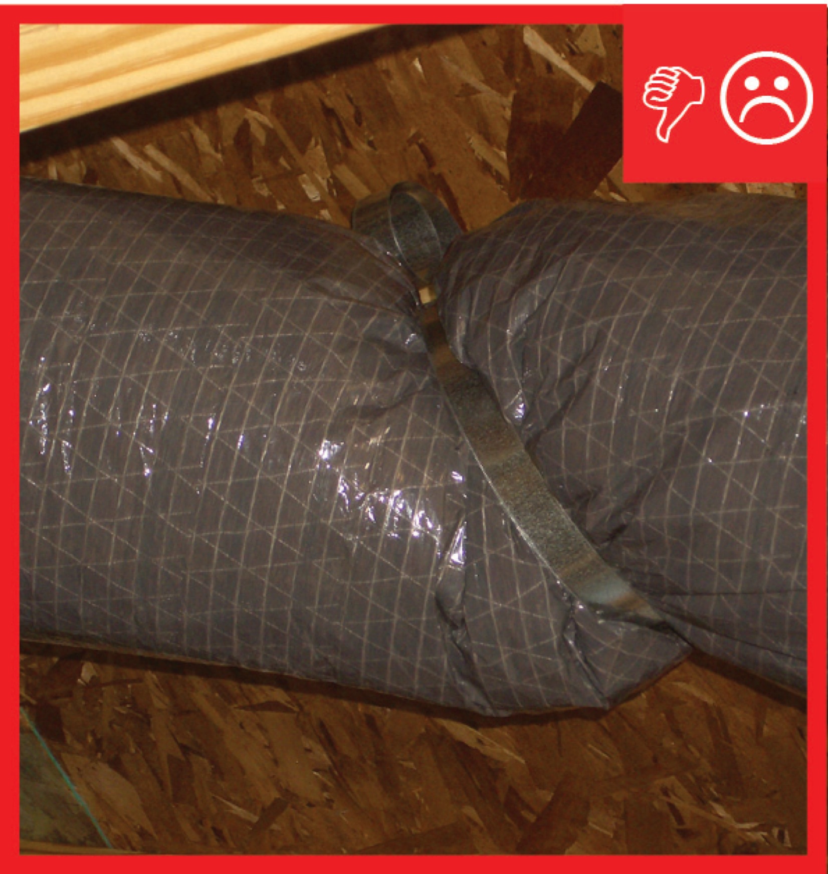
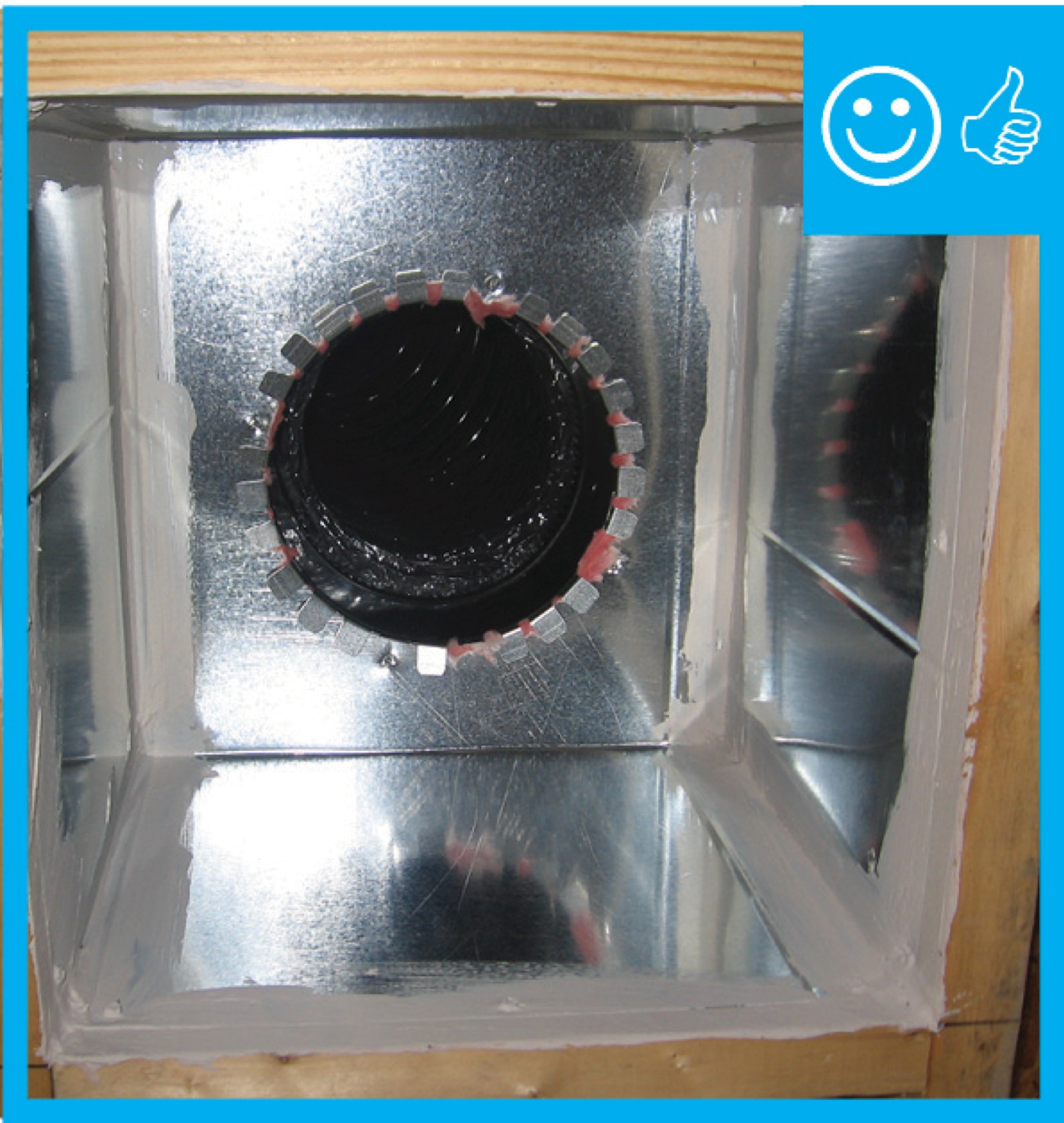
Pull the insulation and outer liner of the flex duct over the collar to come in full contact with the liner and insulation of the trunk line or fitting and tape in place
Image
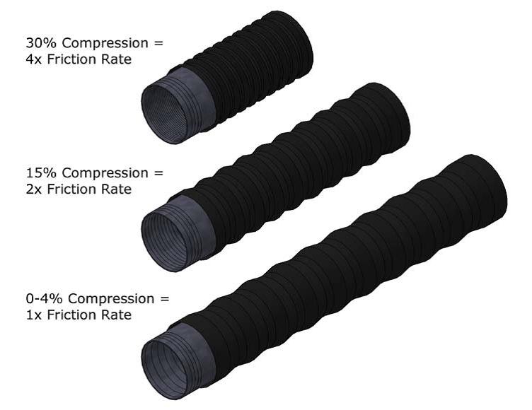
Pulling flex duct taut when installing greatly reduces the amount of friction caused by the ducting
Image
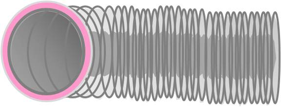
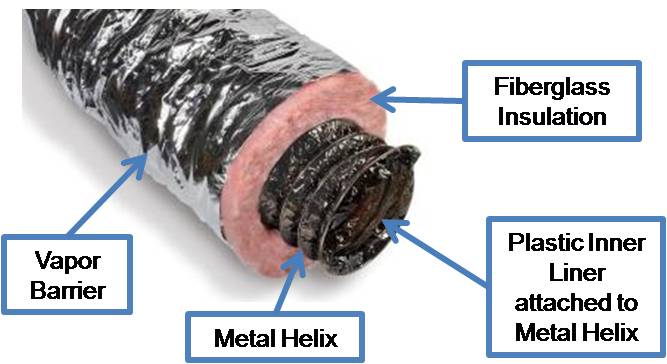
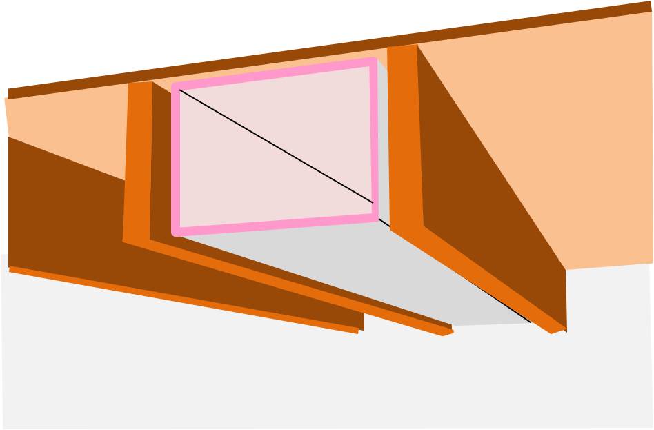
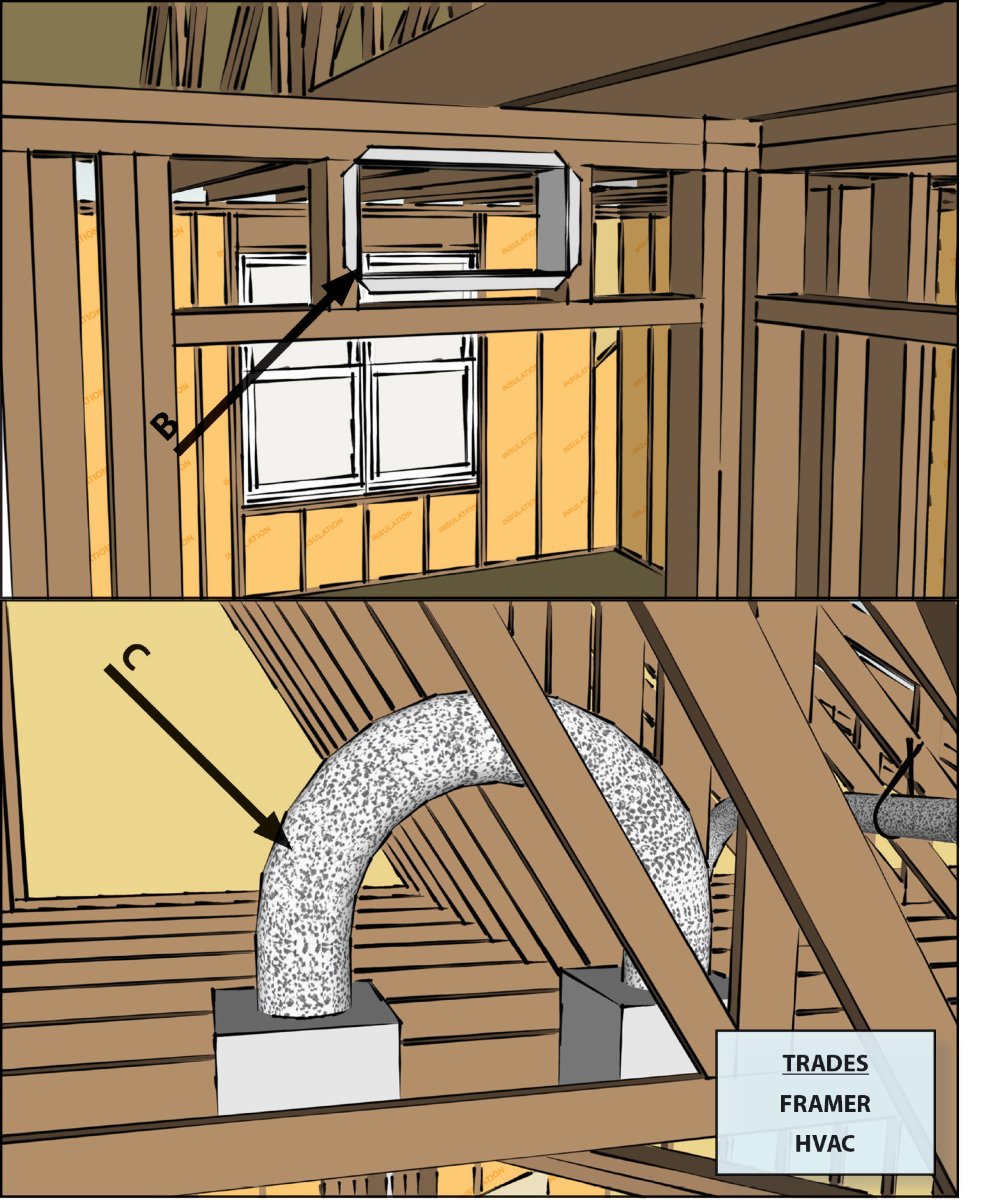
R-6 flexible duct has 2 inches of insulation around the inner liner so a 12-inch duct requires a 16x16-inch chase
Image
Raised ceiling chase sealed with drywall mud
Image
Raised ceiling duct chase is not visible as finished product
Image
Rater-measured duct leakage to outdoors ≤ 4 CFM25 per 100 sq. ft. of conditioned floor area
Image
Image
Image
Image
Image
Image
Right - a dropped ceiling below a taped plywood air barrier provides a service cavity for ducts and wiring.
Image
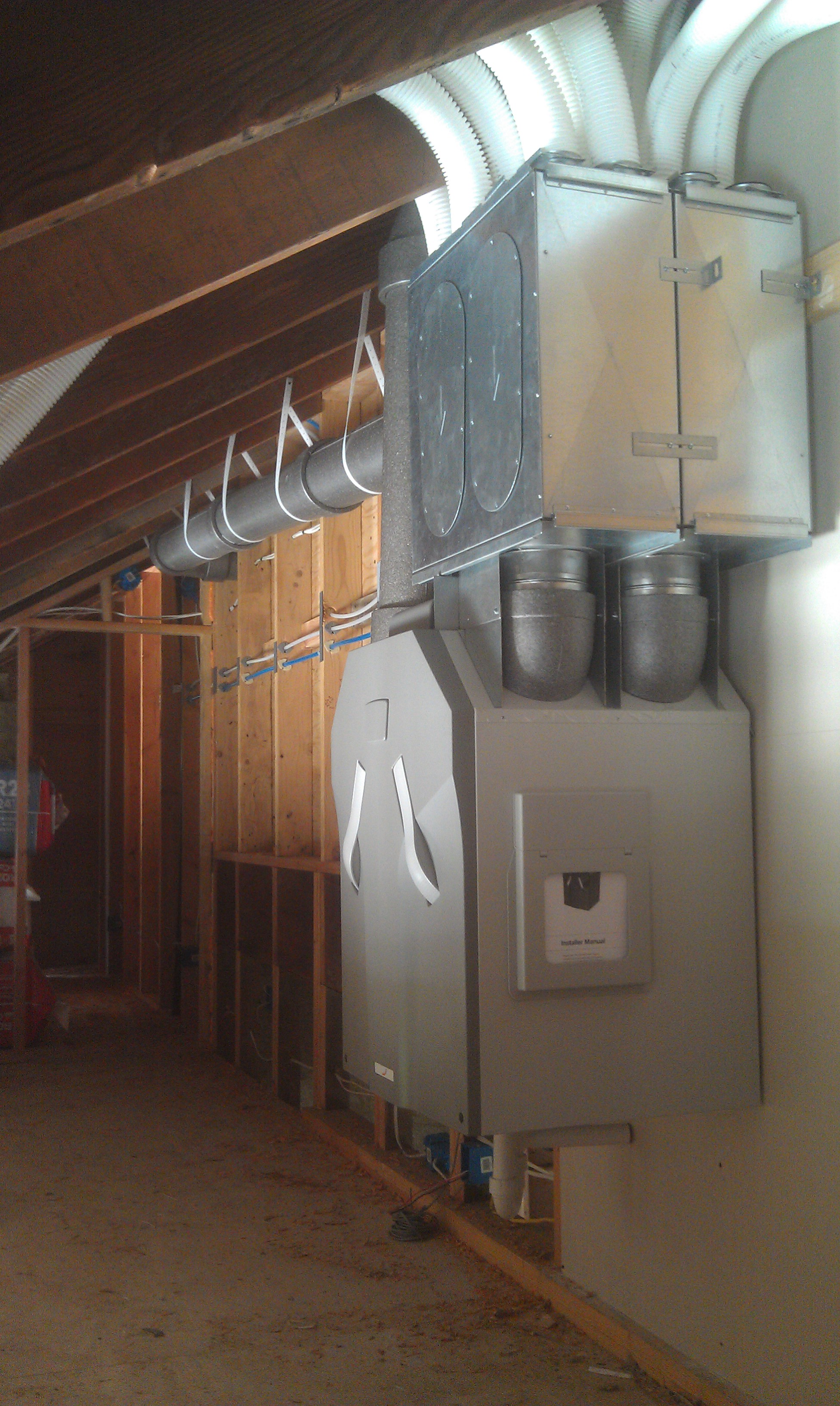
Right - A heat recovery ventilator supplies all living spaces with fresh air while transferring heat for energy savings.
Image
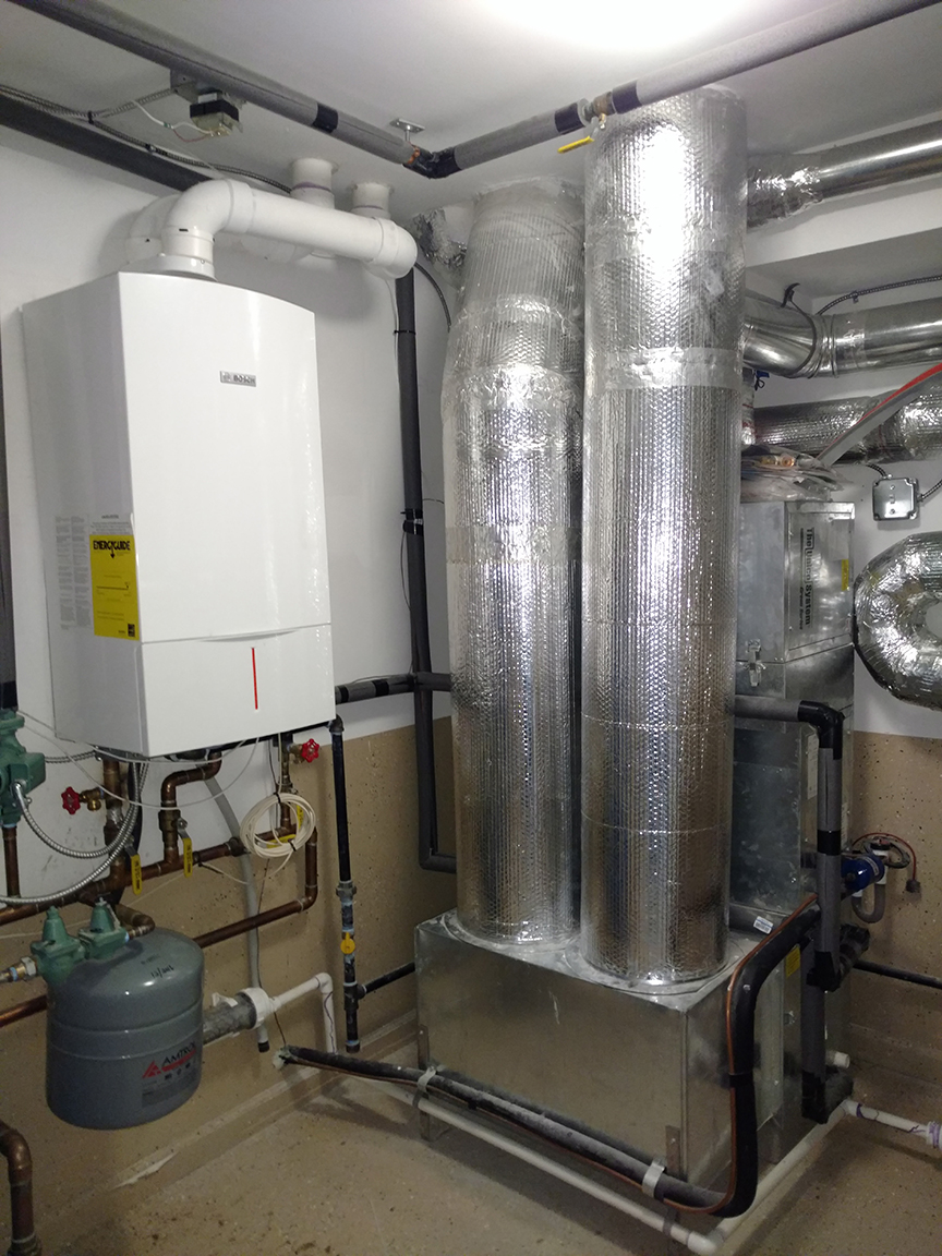
Right - A high-efficiency (95 AFUE) wall-hung gas-fired boiler heats water for the hydro-coil space heating system and also provides a back-up for the solar hot water system.
Image

Right - All seams in the HVAC equipment and ductwork are sealed with mastic; because the HVAC equipment is in the garage, it is an air-sealed closet.
Image
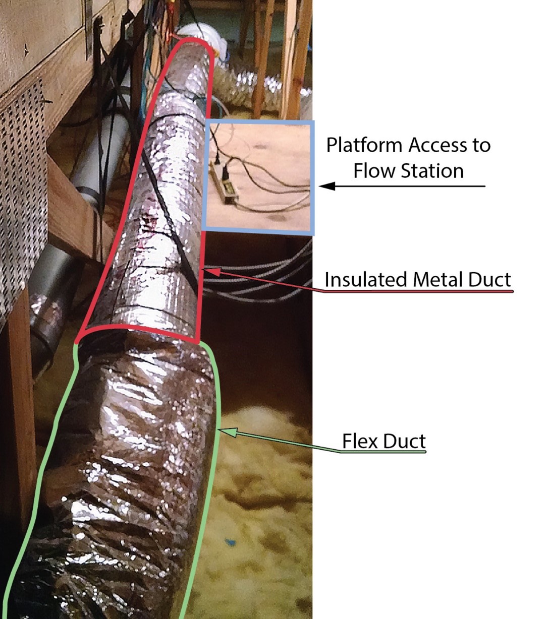
Right - An in-line air flow testing station is installed in a straight section of smooth metal duct (red outline) to determine the air flow rate of a fresh air intake for a whole house ventilation system.
Image
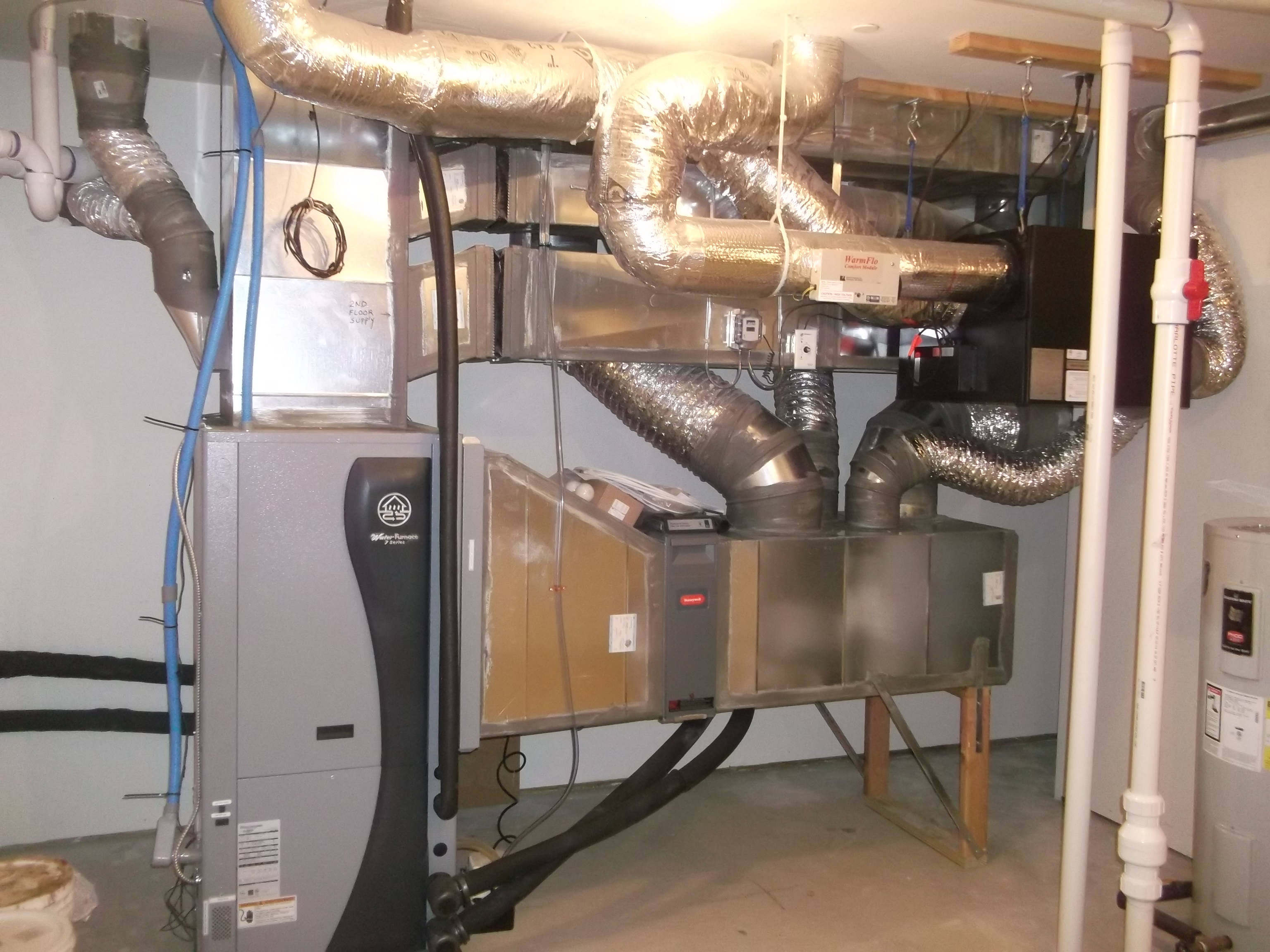
Right - An ultra-efficient (COP 5.7) ground source heat pump provides hot water to an air coil in the central air handler which uses a variable-speed electrically commutated fan motor to distribute conditioned air to the home’s ducts.
Image
Right - Drywall was installed before installing the duct chase to ensure the ducts will be separated from the attic.
Image
Image

Right - Flex duct installed with adequate support and pulled taut to provide adequate air flow
Image
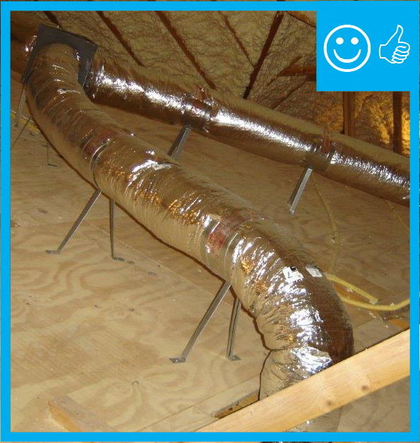
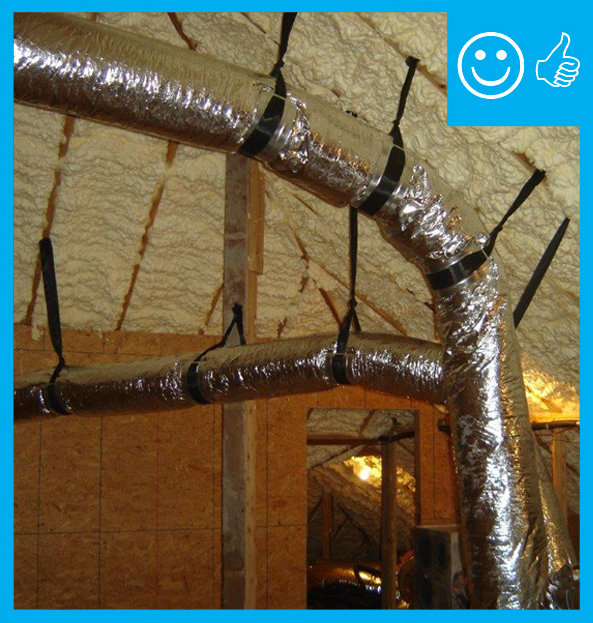
Right - Flex duct installed with frequent supports, straight runs, and gradual turns to allow good air flow
Image
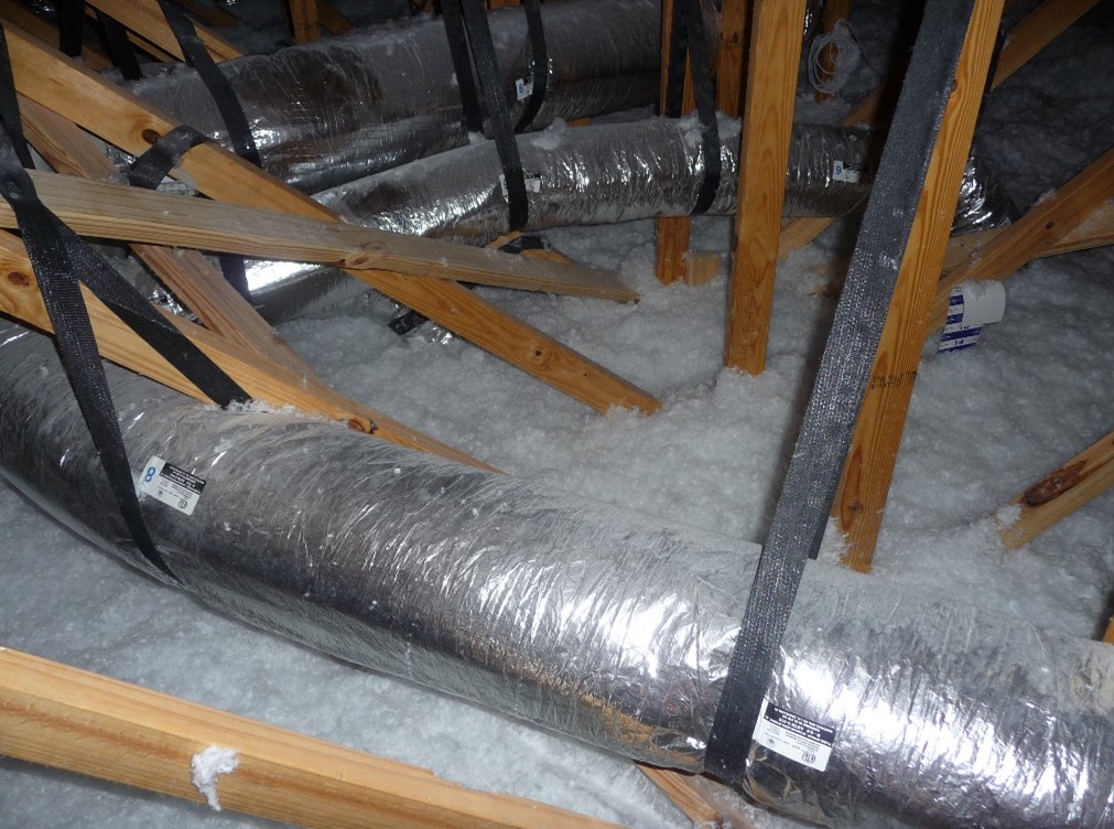
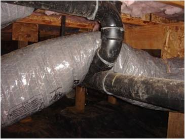
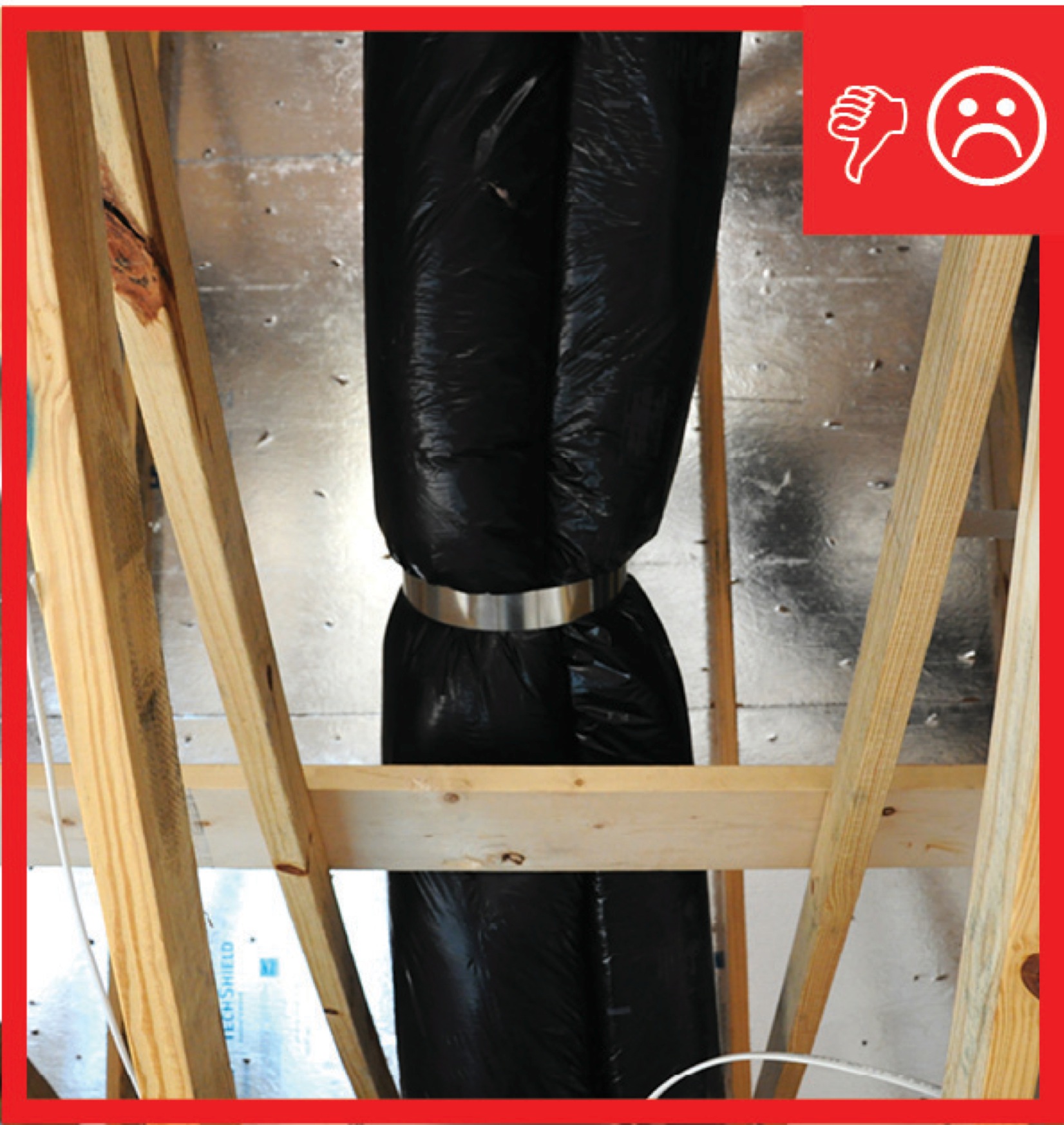
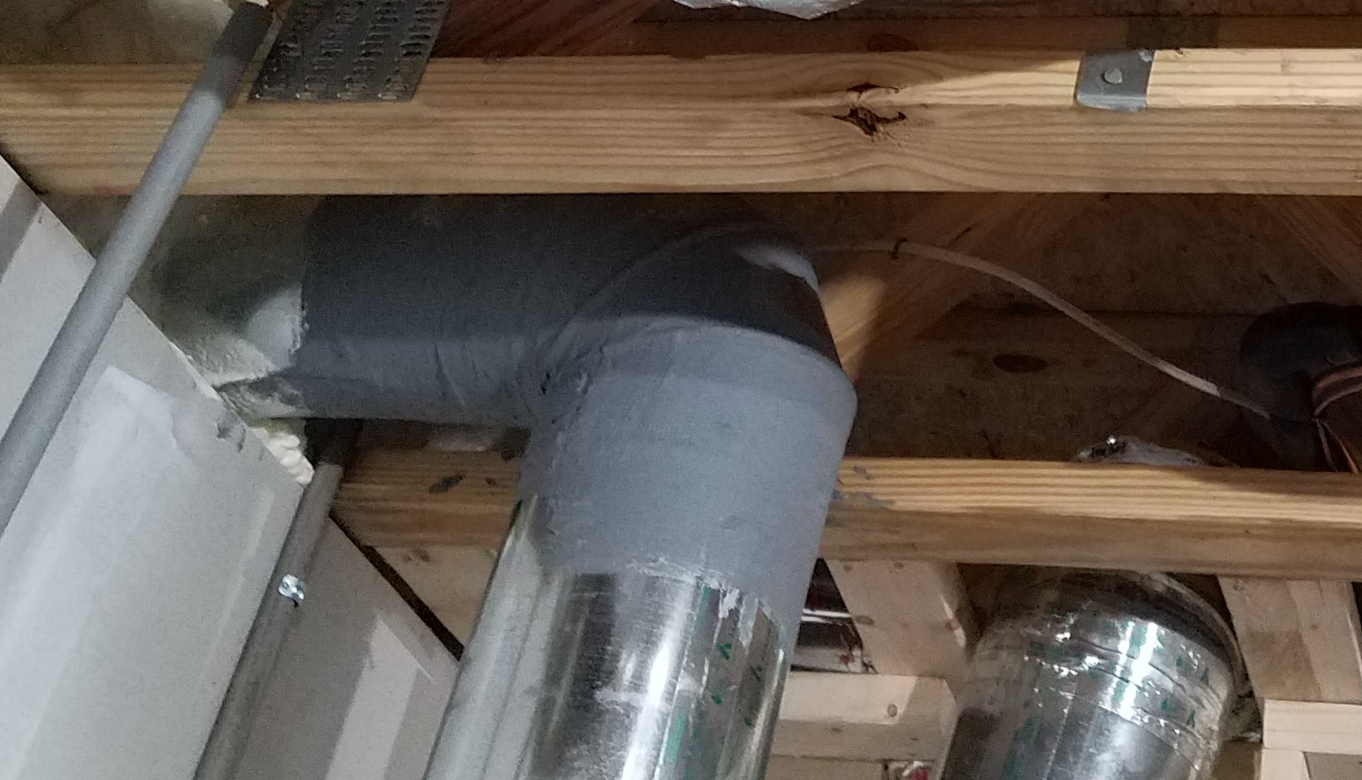
Right - HVAC ducts should be well-supported with minimal bends and pinching.
Image
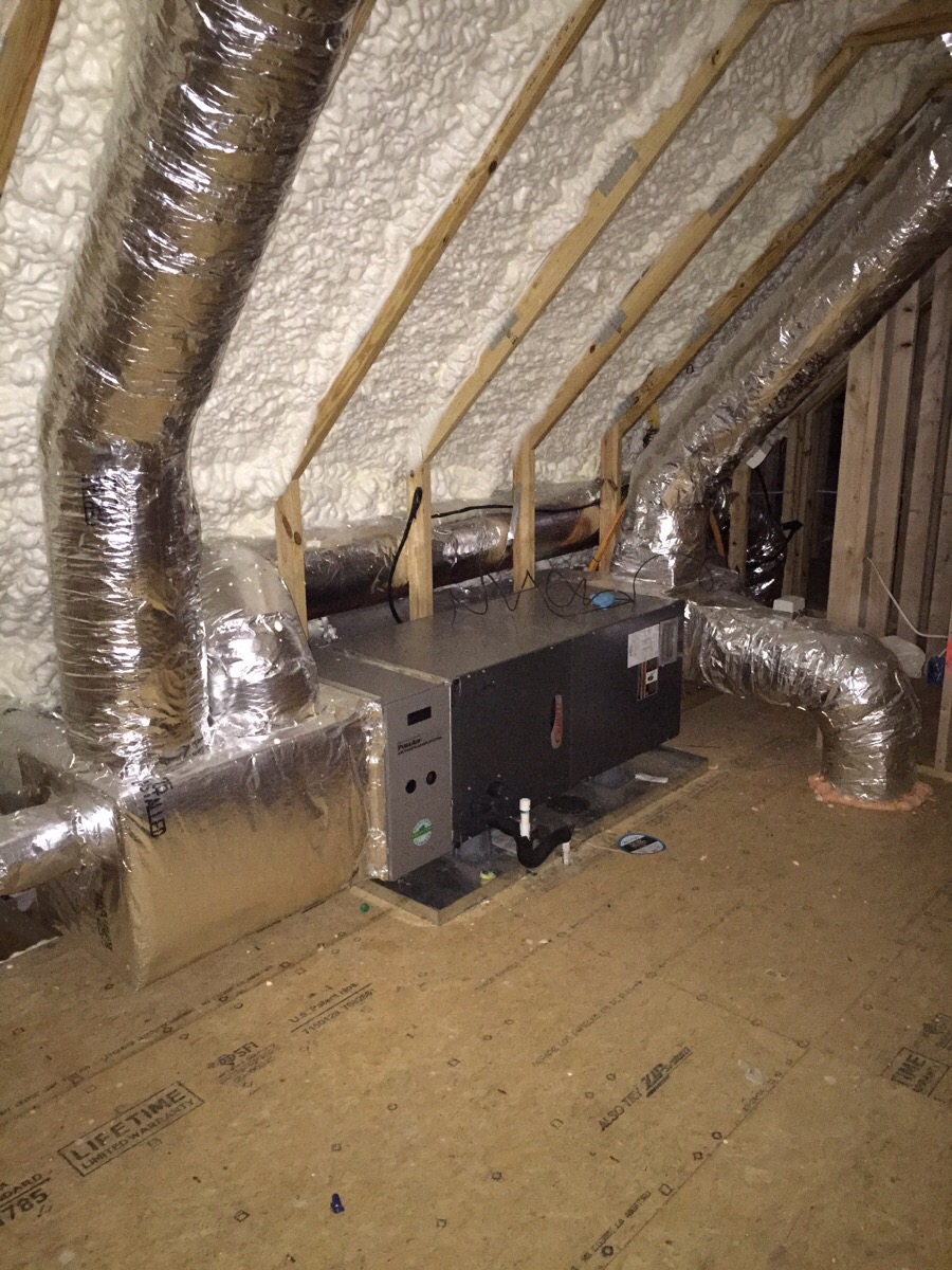
Right - Open-cell polyurethane spray foam to R-28 on underside of roof turns new attic into conditioned space for HVAC.
Image
Image
Image
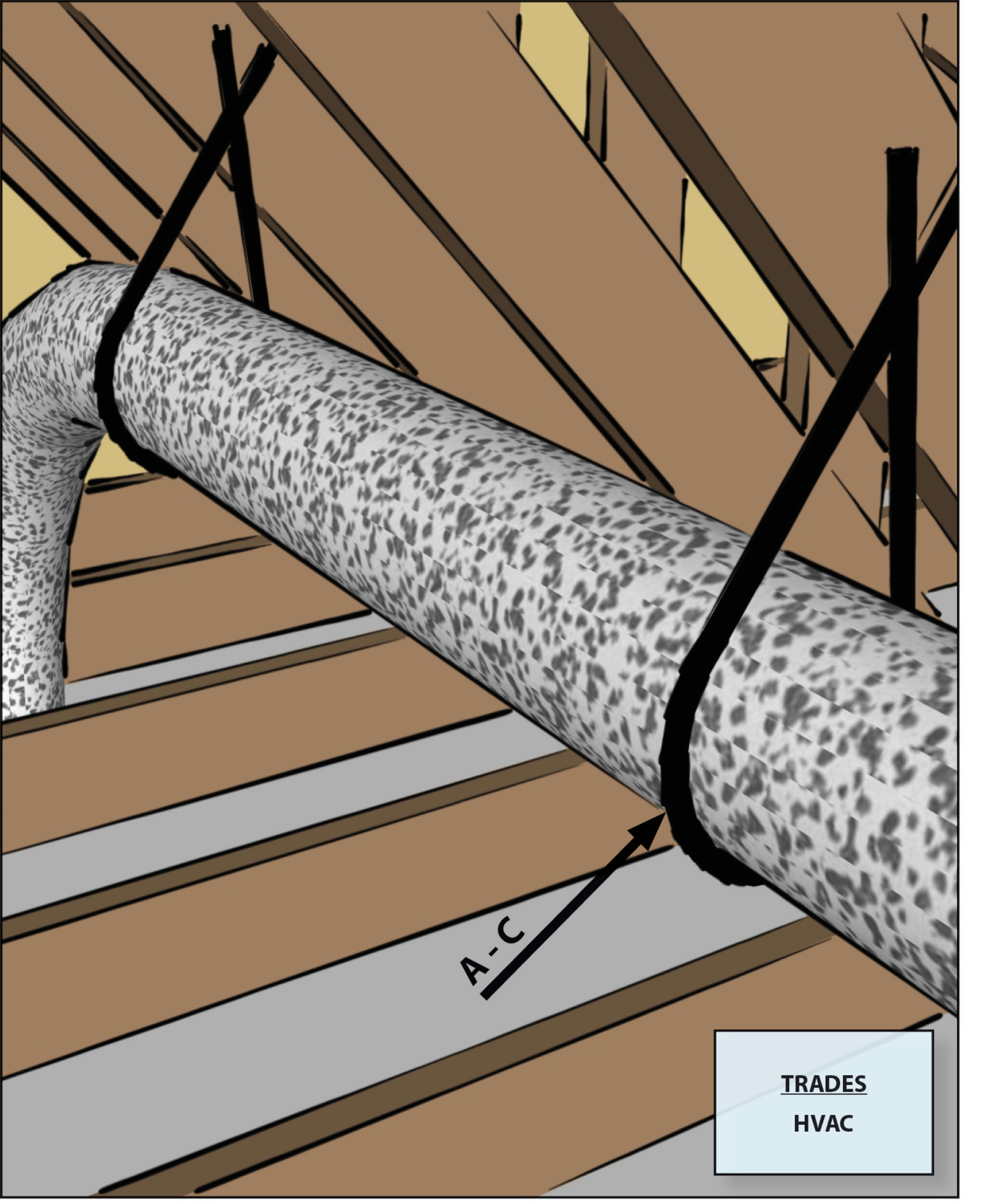
Right - Straps are spaced close enough together to provide adequate support of the flex duct
Image
Right - The butterfly damper of this crawlspace supply register opens when the HVAC fan is running; the damper duct is sealed with mastic and supported by strapping.
Image
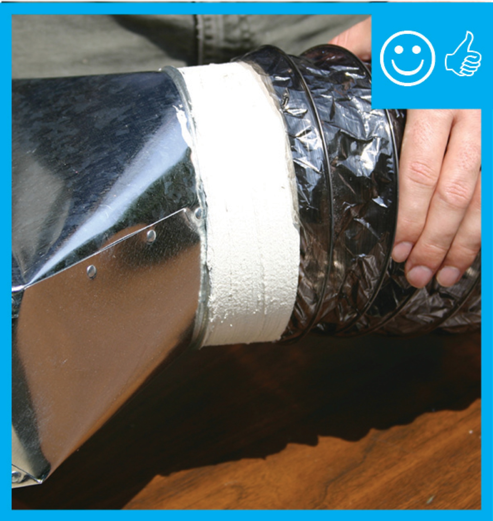
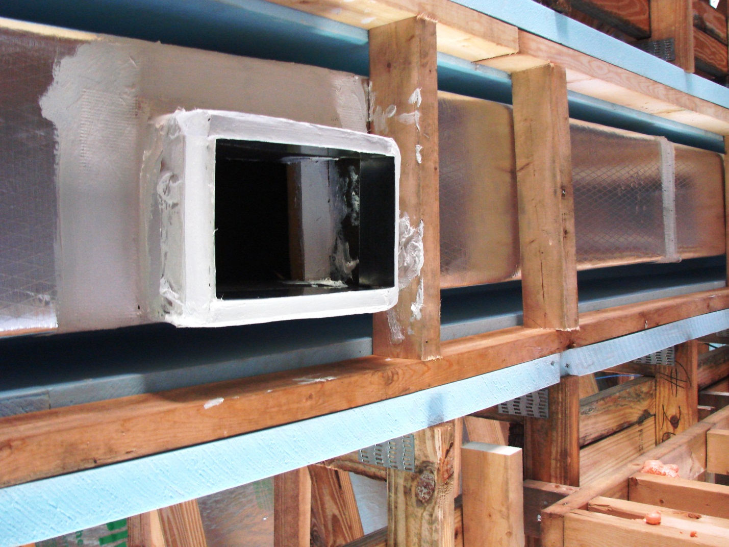
Right - The duct shows redundant sealing including the caulk, tape, and flashing
Image
Image
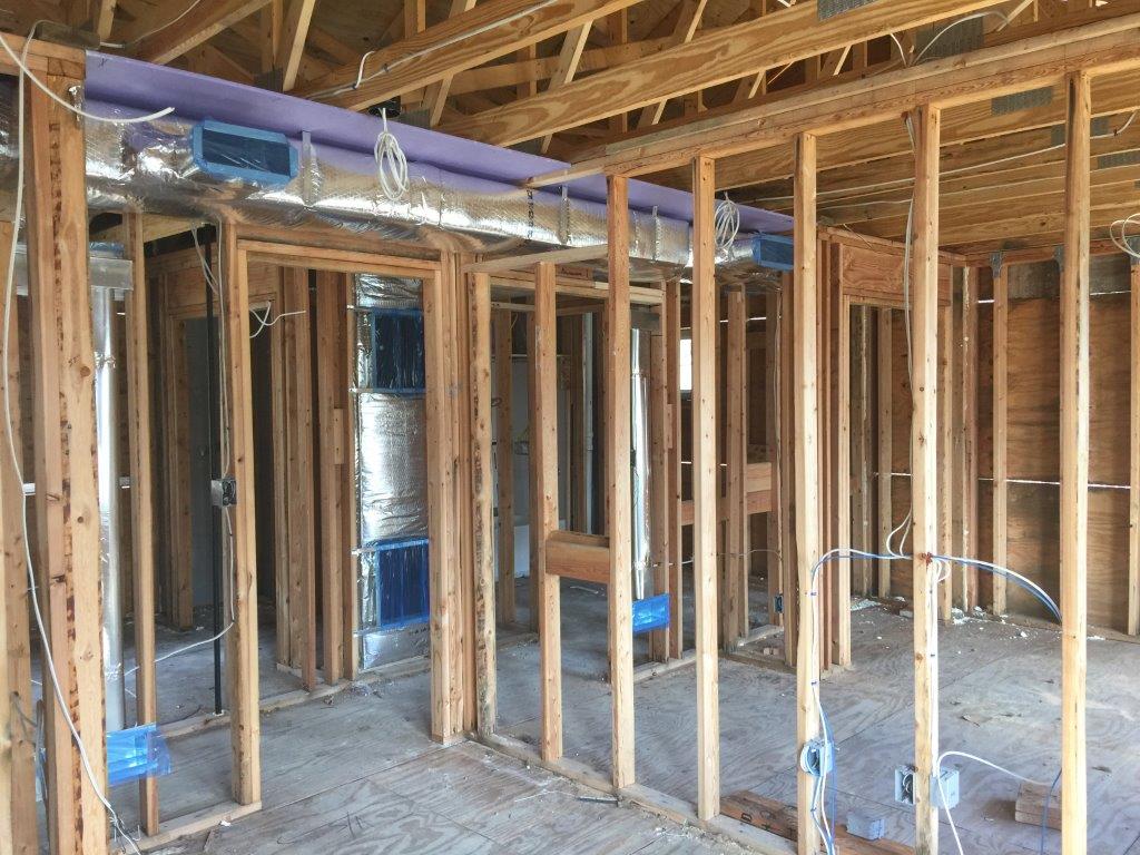
Right - The HVAC ducts are located in conditioned space in a dropped hallway ceiling with very short duct runs for more efficient delivery.
Image
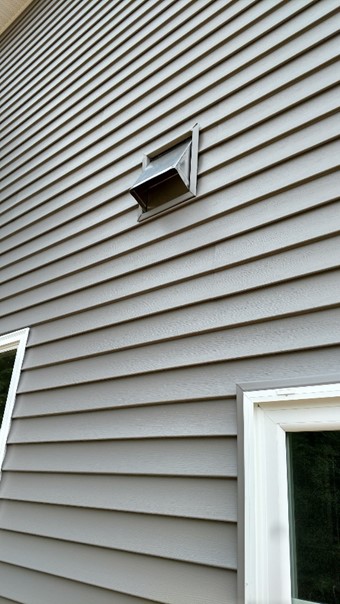
Right - The kitchen exhaust duct termination is integrated aesthetically and functionally with the exterior cladding; however, the opening should be screened to keep out pests.
Image