Showing results 1 - 229 of 229
Image
Image
A constant airflow regulator is a modulating orifice that automatically regulates airflows in duct systems to constant levels
Image
A constant airflow regulator is fitted into the neck of the supply duct to control air flow to deliver the design airflow regardless of pressure variations
Image
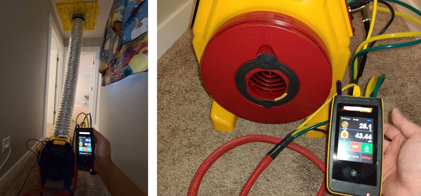
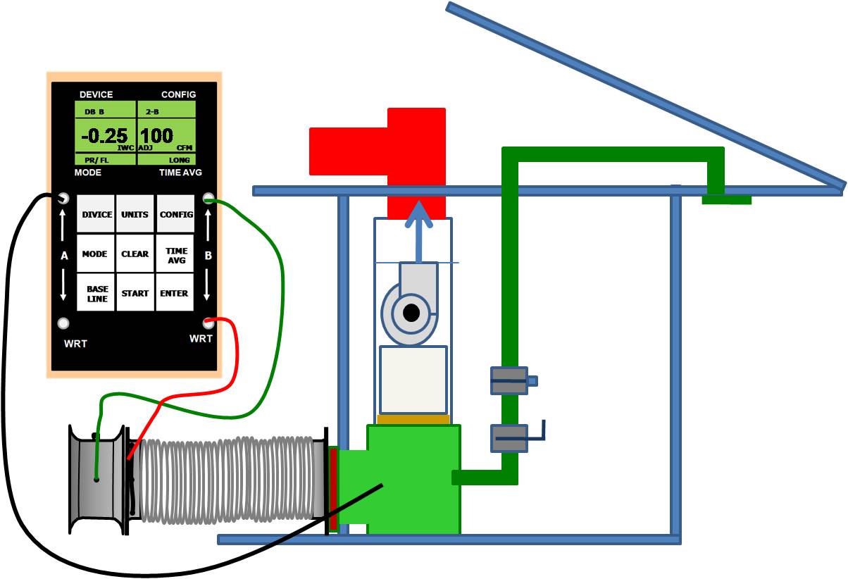
A duct leakage test is performed on a ducted heat pump system using a duct tester (blower fan) and a digital manometer.
Image
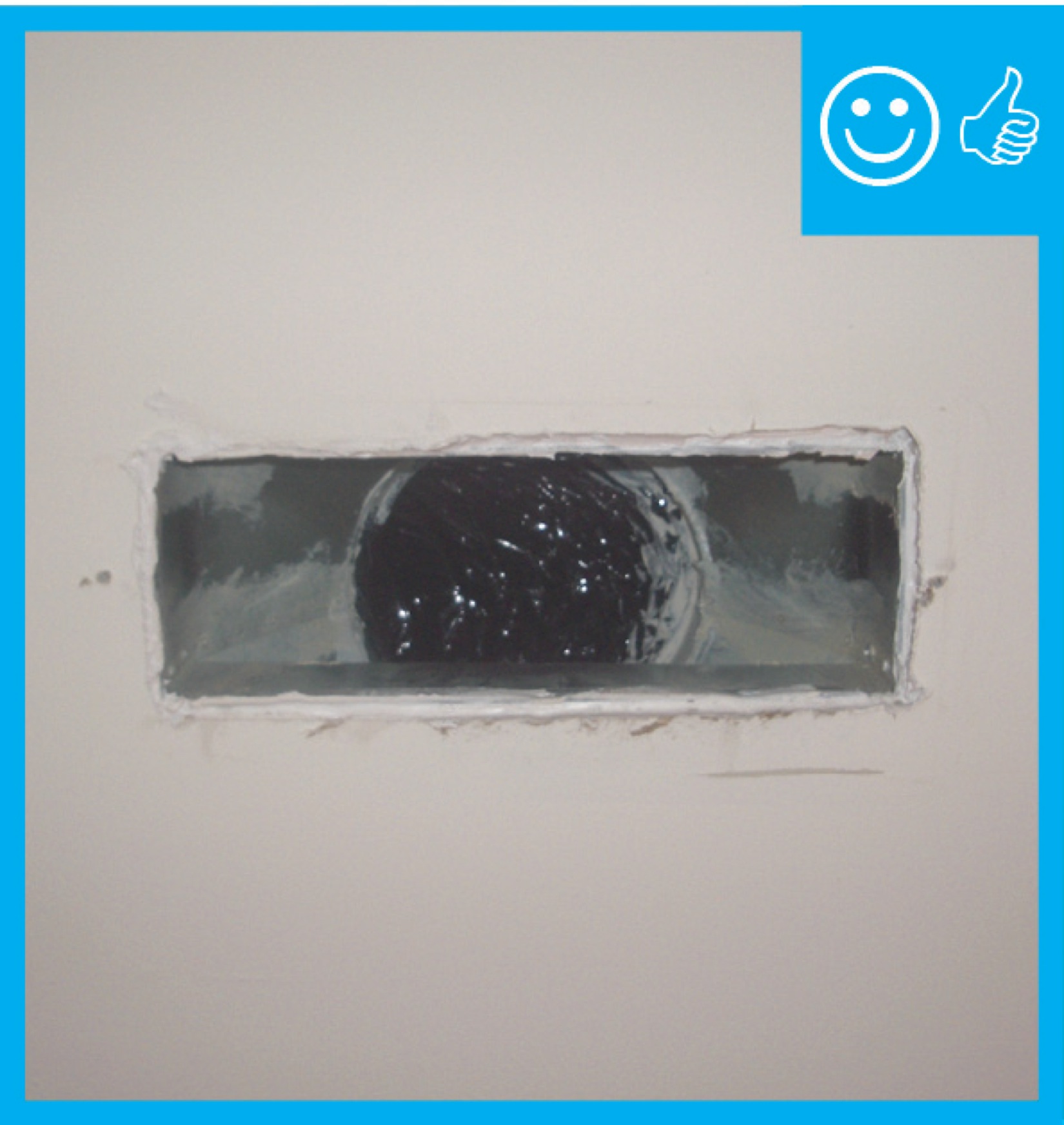
A ducted central return brings air from central return registers back to the air handler through insulated, air-sealed ducts
Image
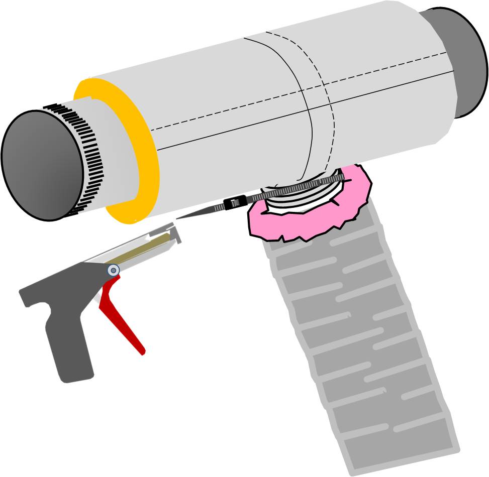
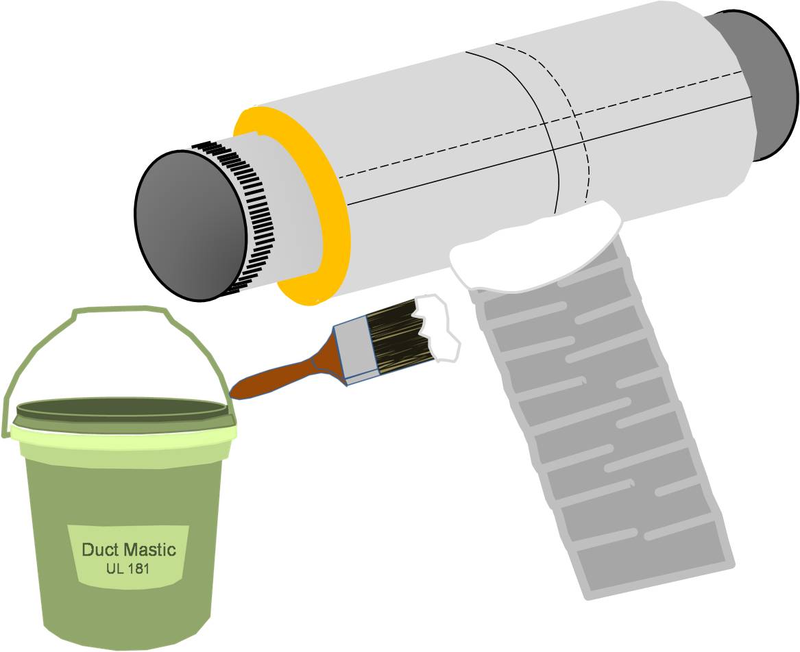
A nylon draw band and tensioning tool are used to secure the inner coil of the pre-insulated flexible duct
Image

A nylon draw band and tensioning tool are used to secure the inner liner of the pre-insulated flexible duct
Image
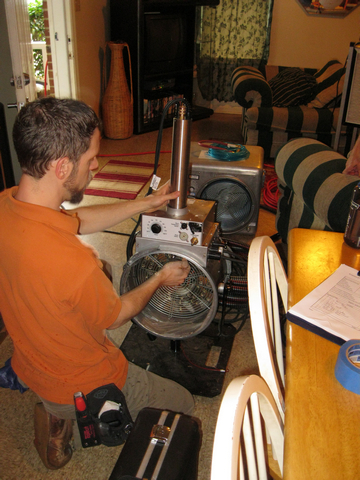
A technician assembles the spray sealant injection system to seal HVAC ducts from the inside
Image

Image
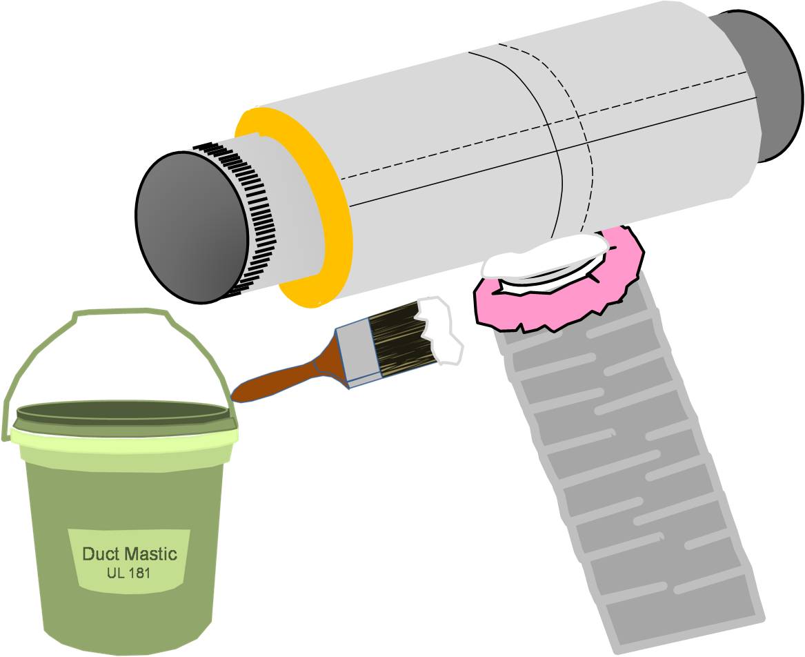
After securing the inner coil, cover the draw band and the seam with a generous amount of mastic
Image
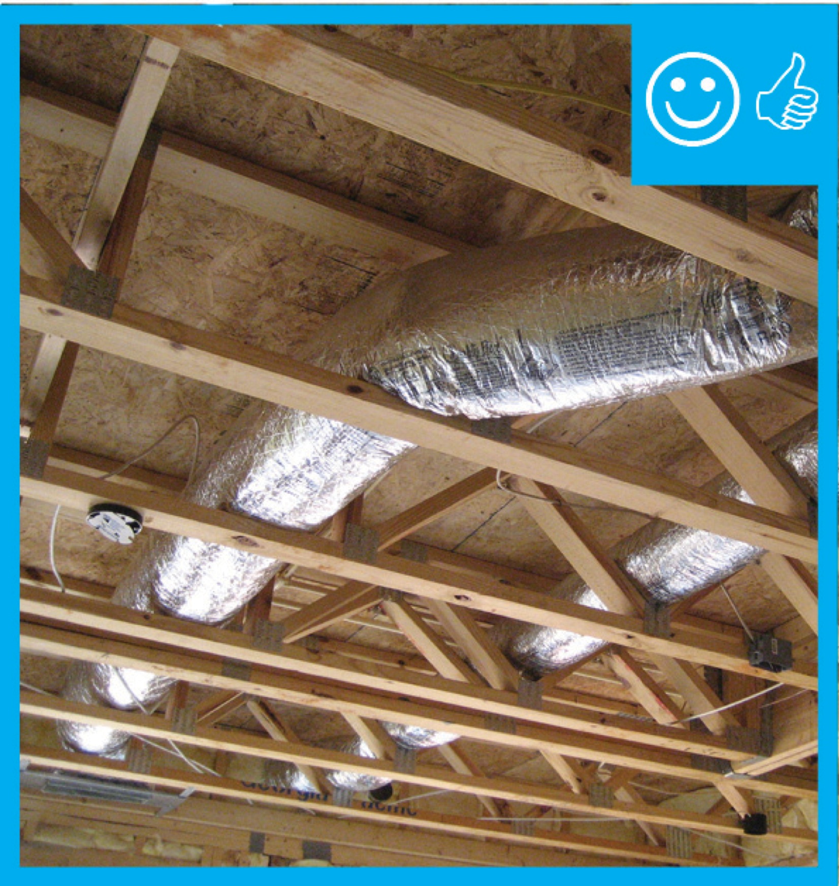
Air seal and insulate flex ducts
Image
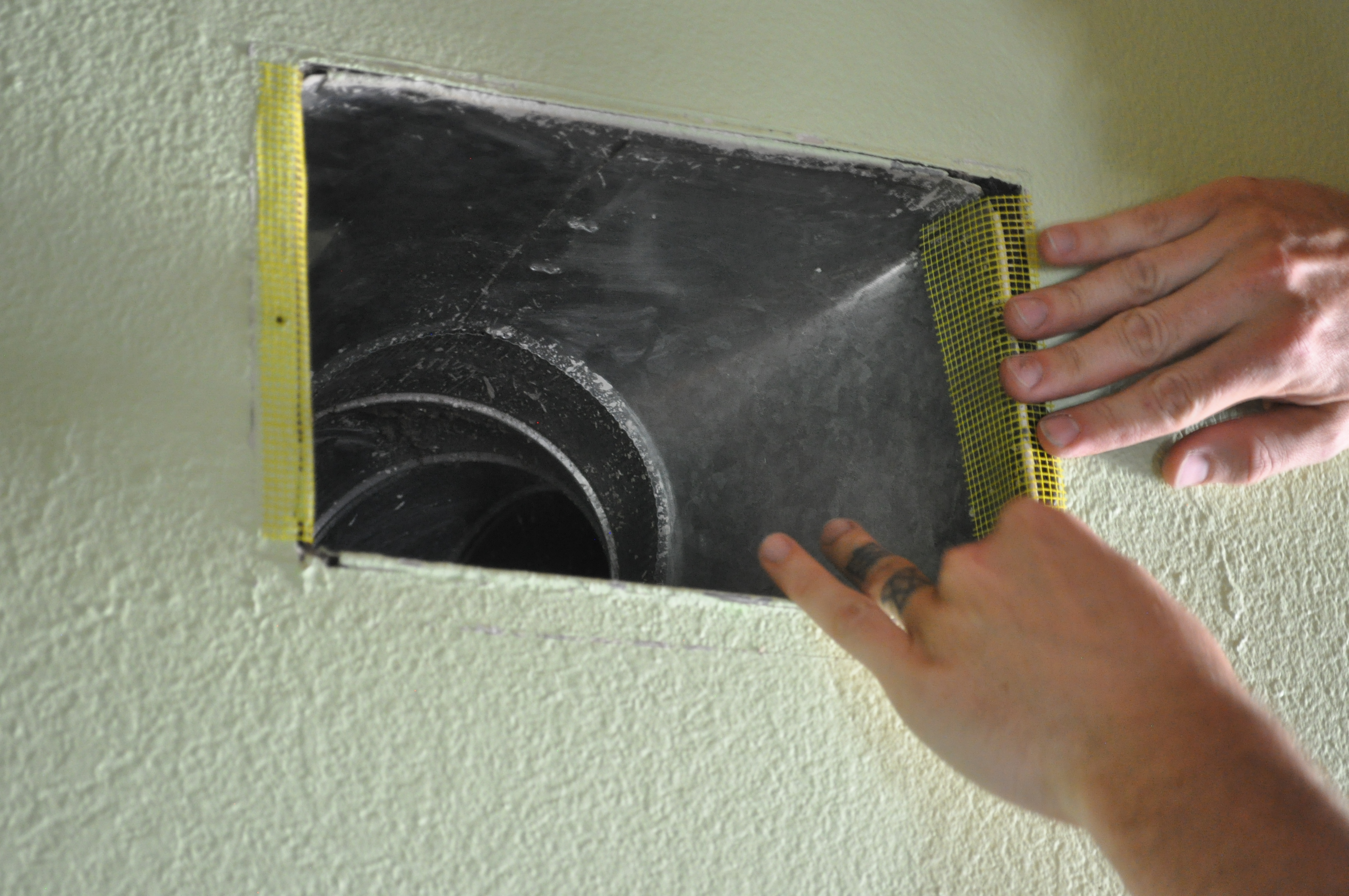
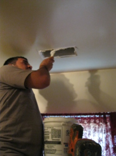
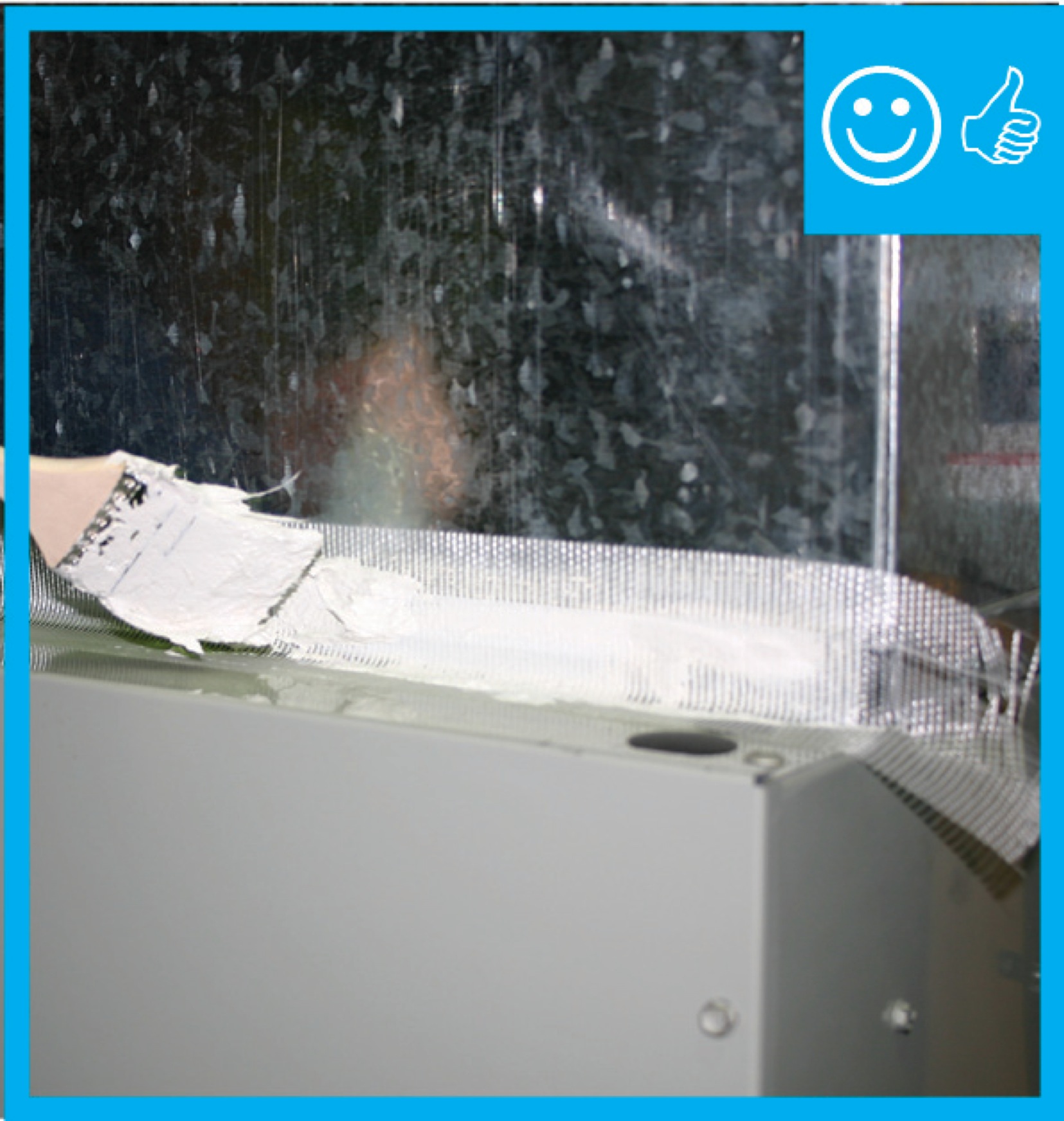
Air seal duct boot to ceiling by installing fiberglass mesh tape and mastic over seam
Image
All other supply ducts and all return ducts in unconditioned space have insulation ≥ R-6
Image
Image
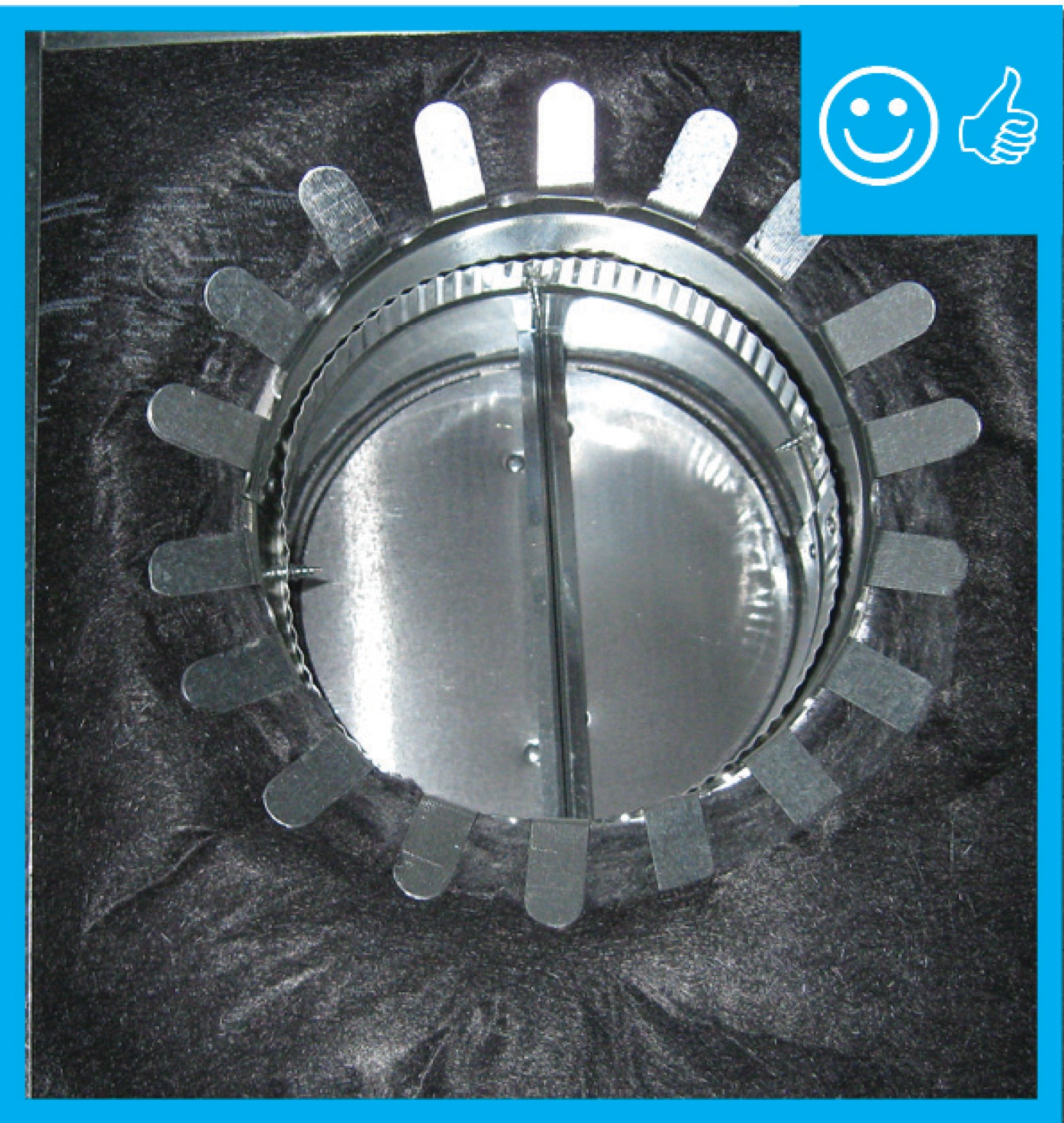
Back-draft damper still has a piece of tape that prevented it from rattling during shipping
Image
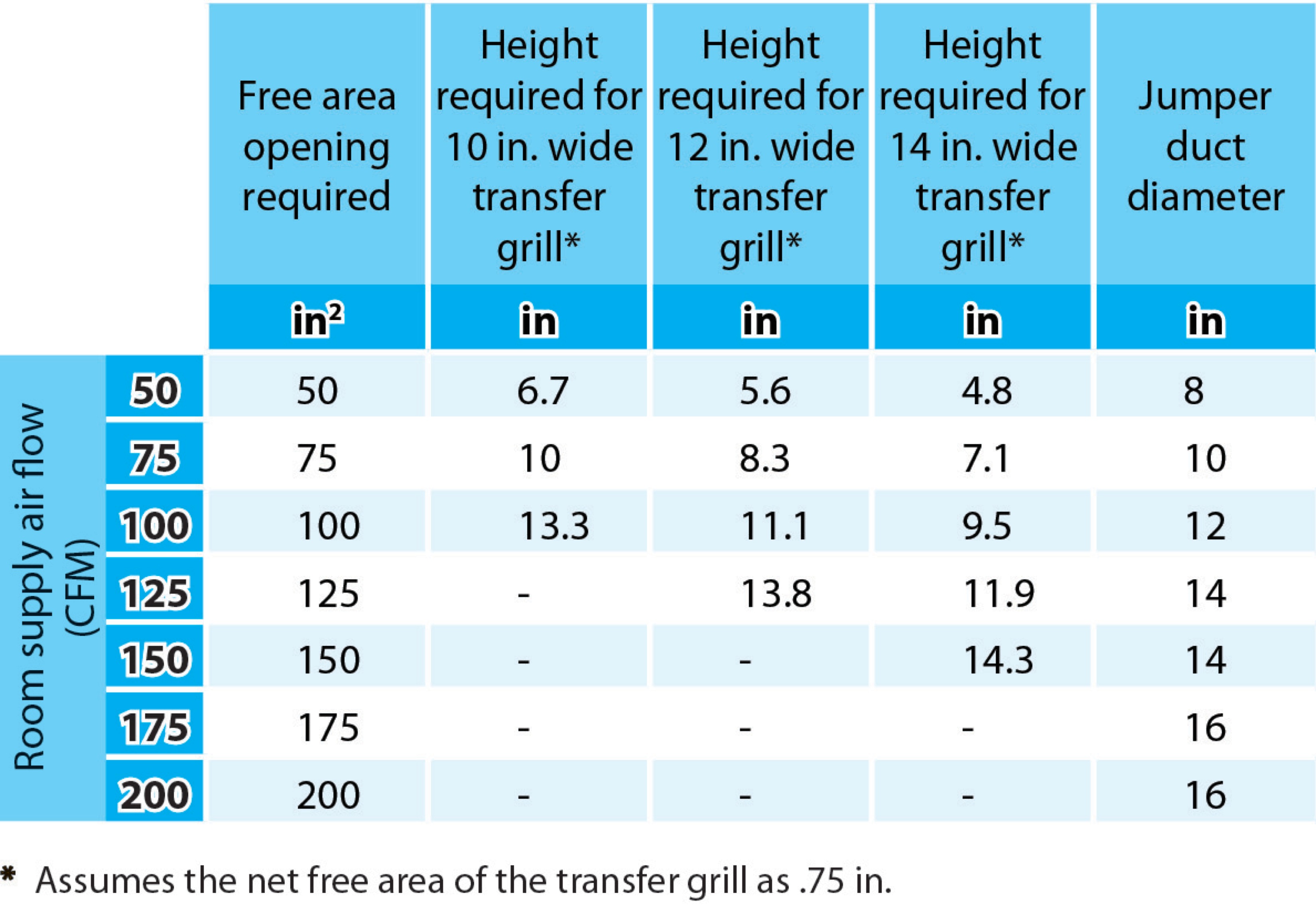
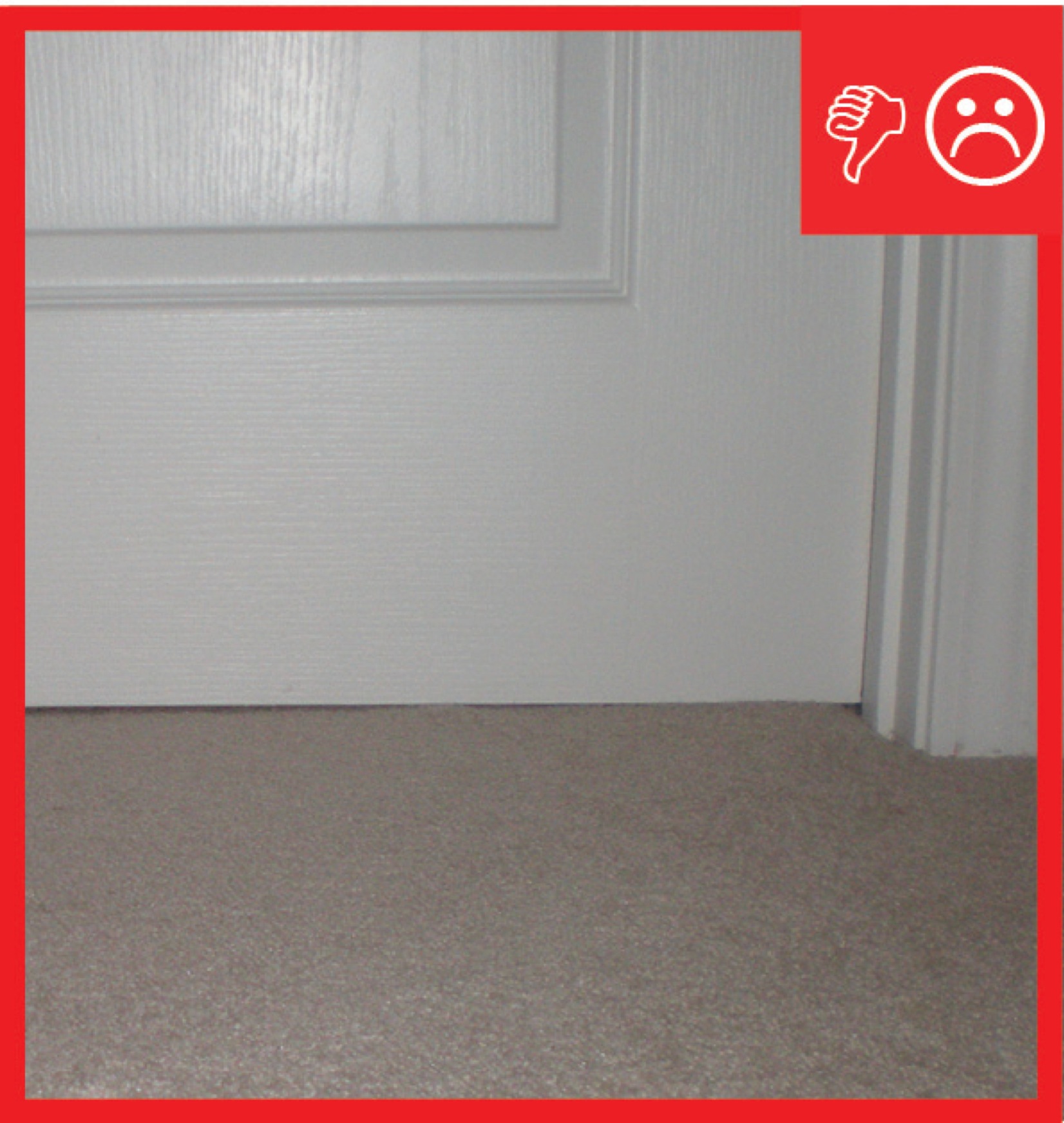
Bedrooms pressure-balanced and provide 1 sq. in. of free area opening per 1 CFM of supply air or achieve a Rater-measured pressure differential ≤ 3 Pa
Image

Bedrooms pressure-balanced and provide 1 sq. in. of free area opening per 1 CFM of supply air or achieve a Rater-measured pressure differential ≤ 3 Pa
Image
Image
Image

Image
Image
Image
Image
Image
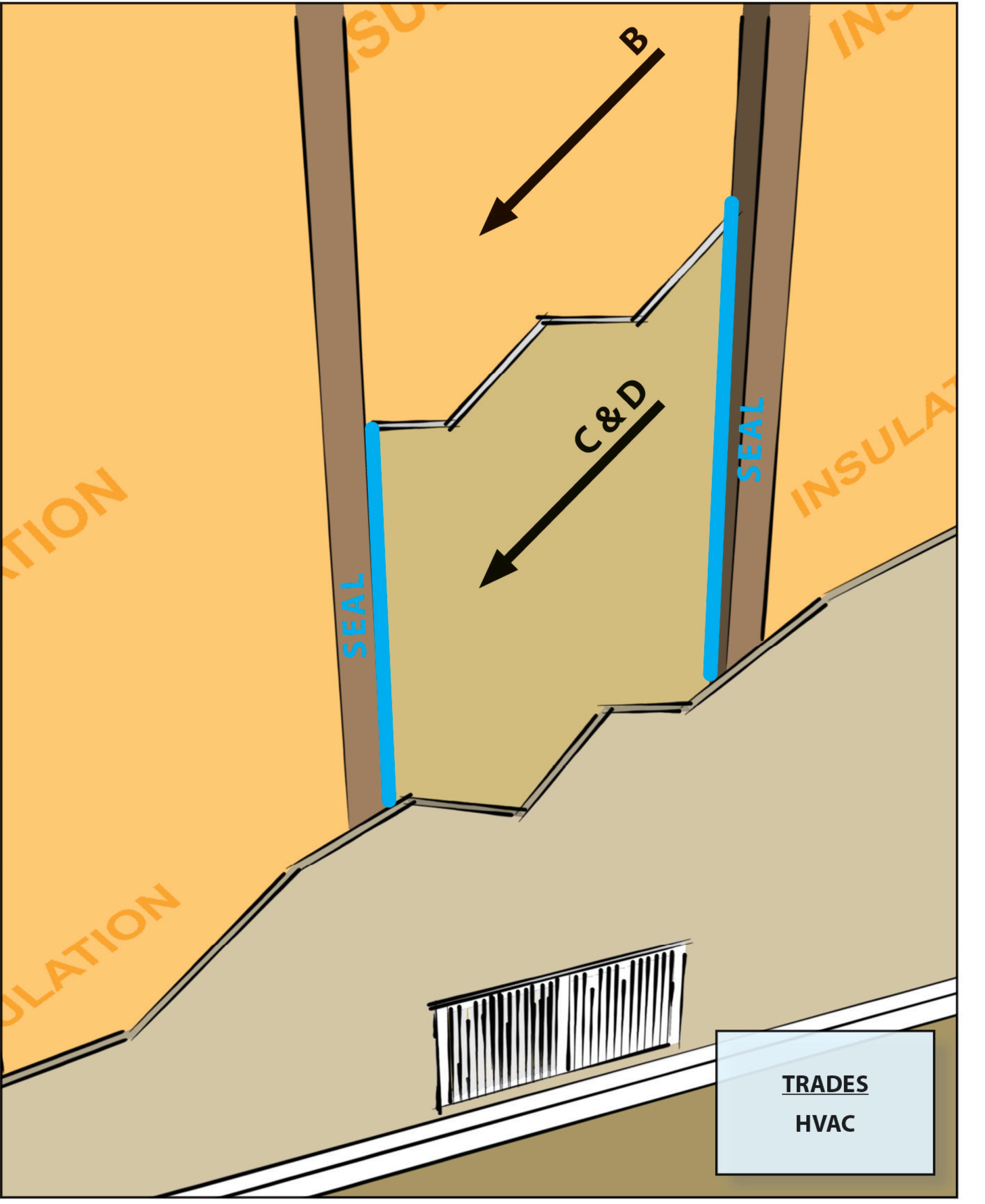
Building cavities not used as supply or return ducts unless they meet Items 3.2, 3.3, 4.1, and 4.2 of this Checklist
Image
Image
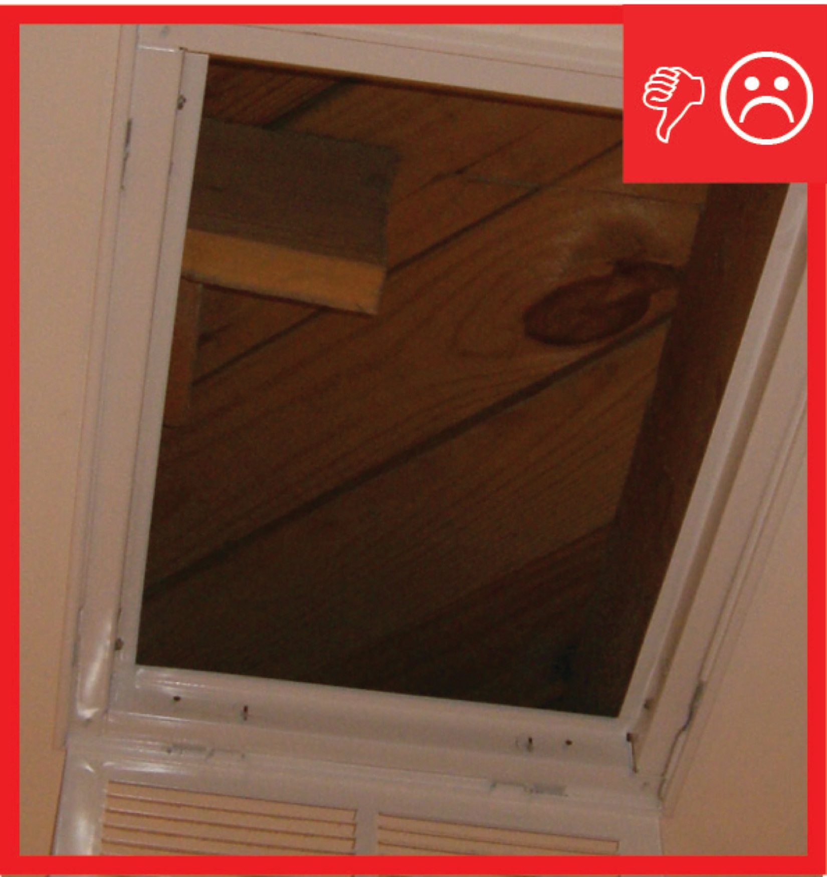
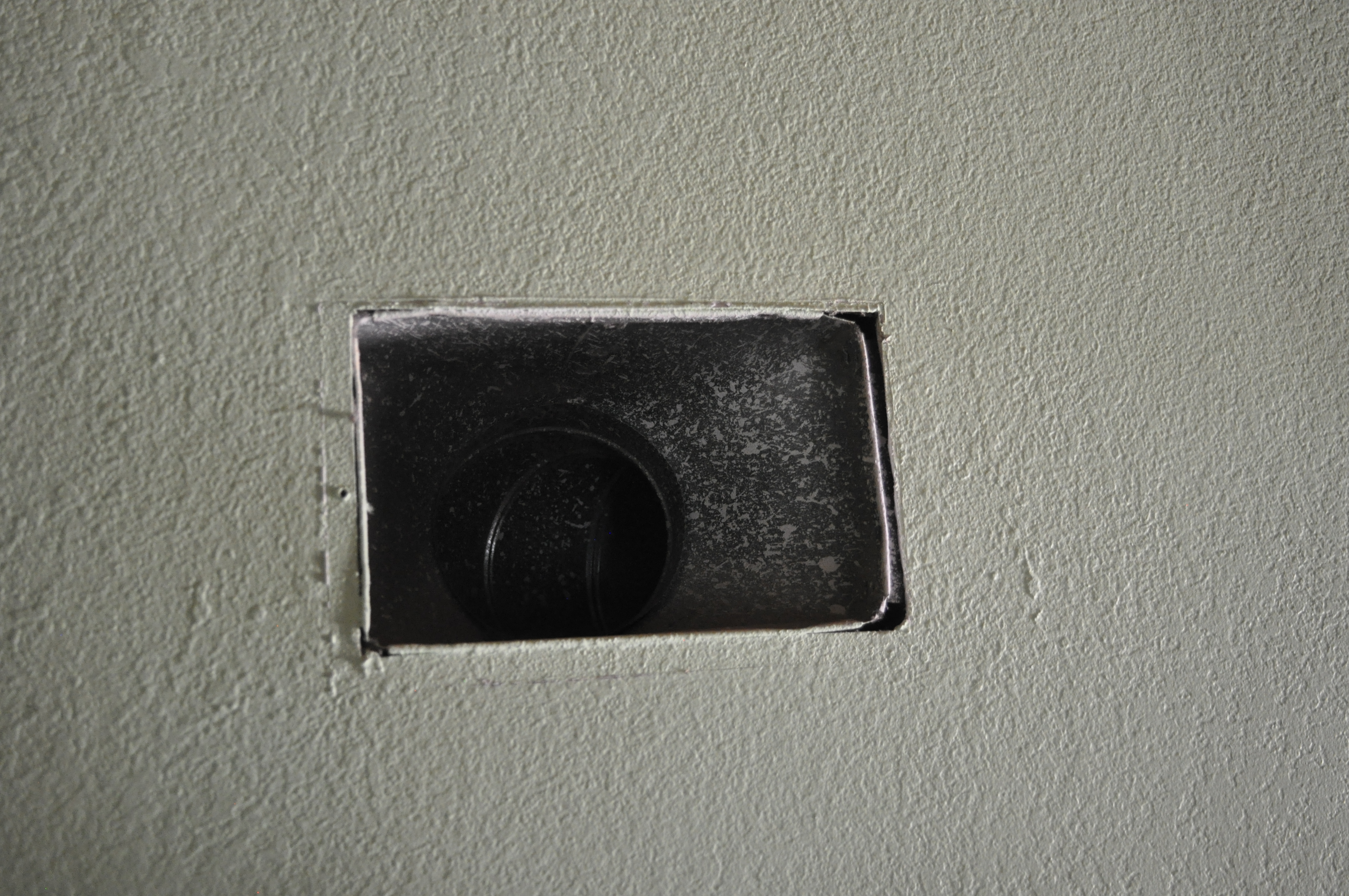
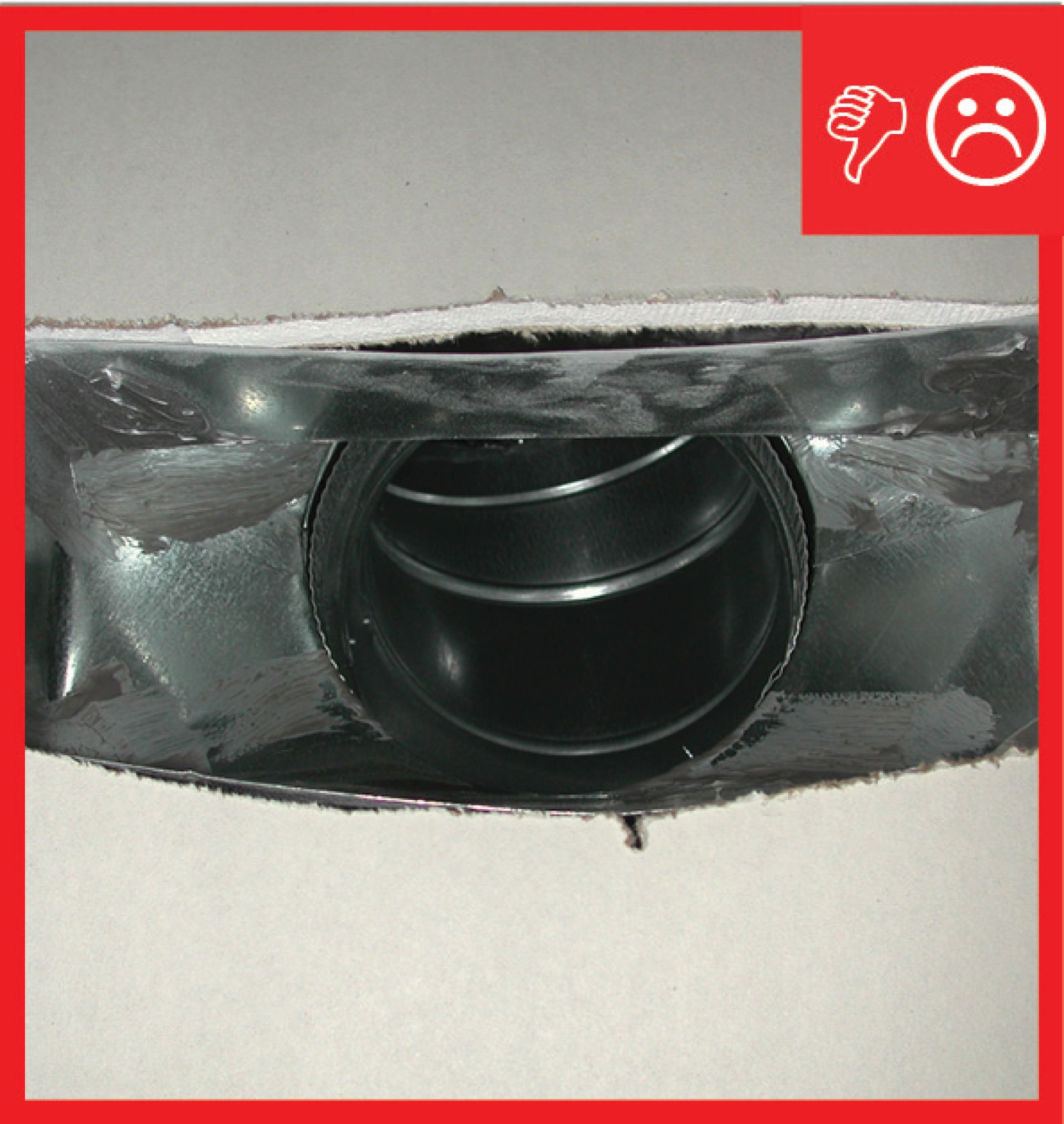
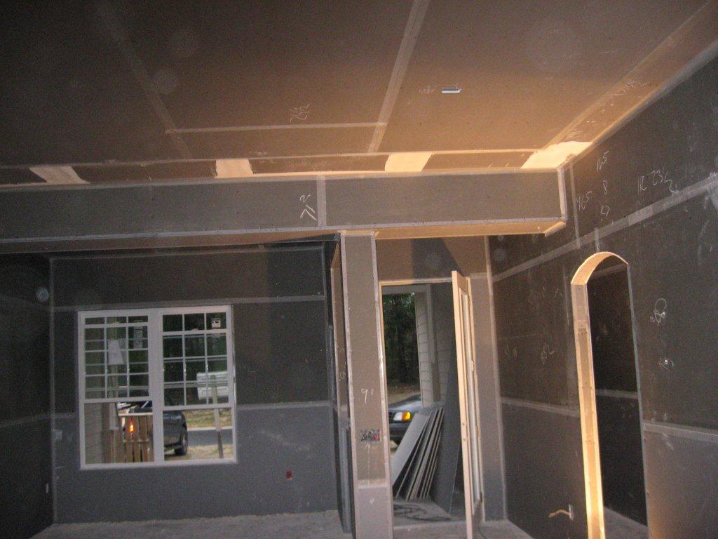
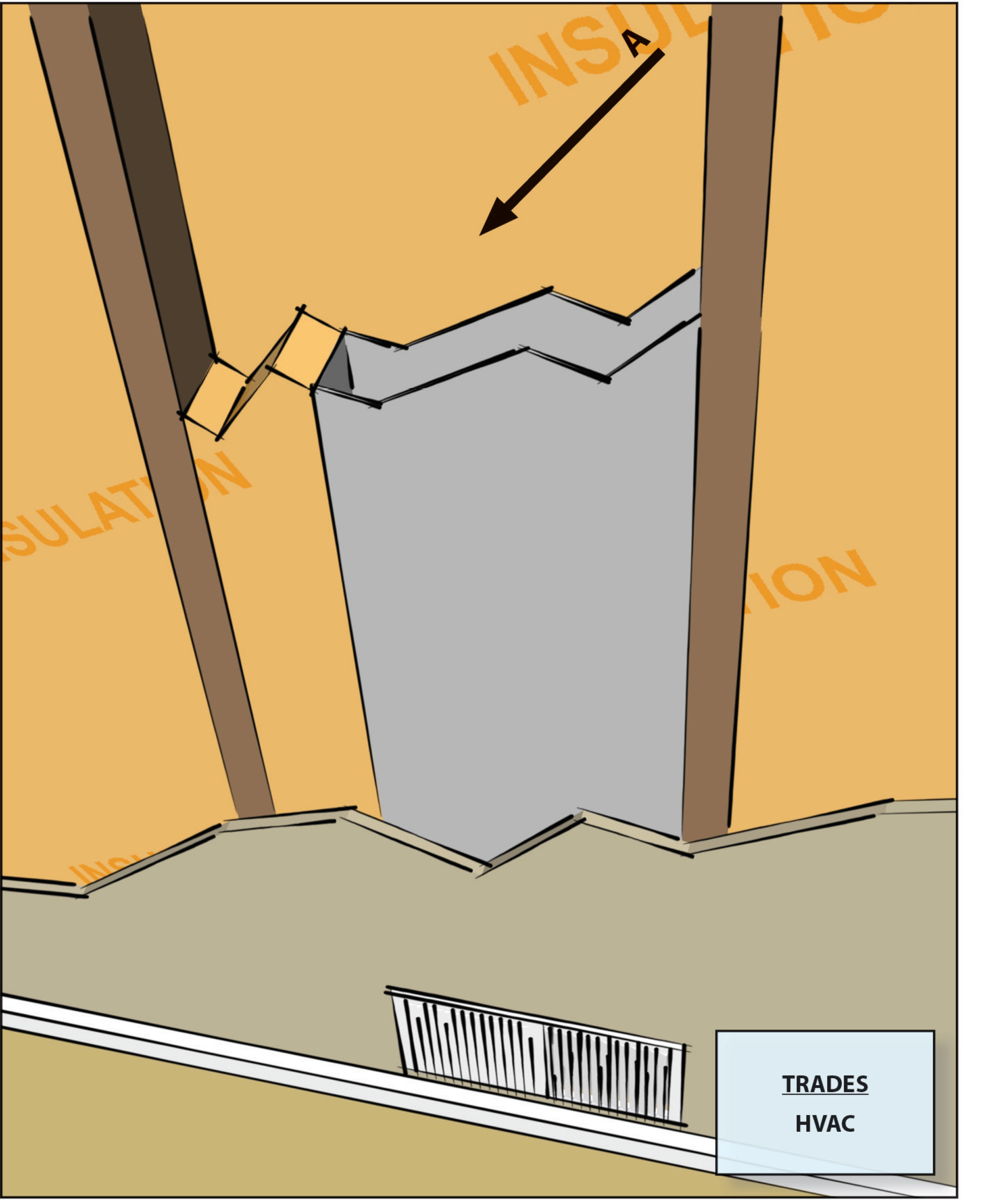
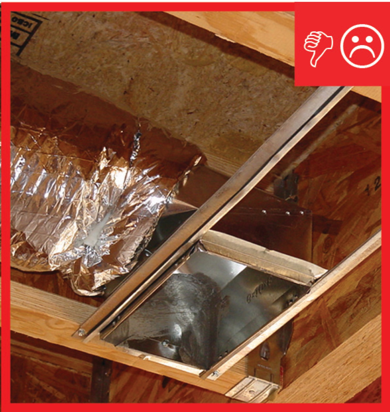
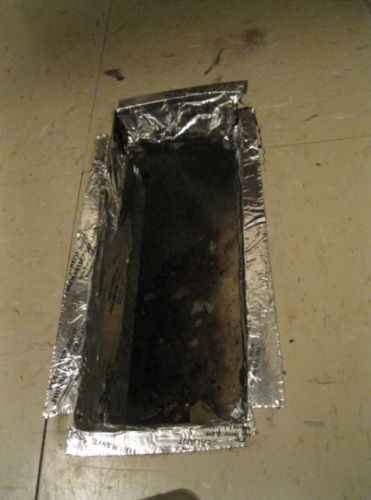
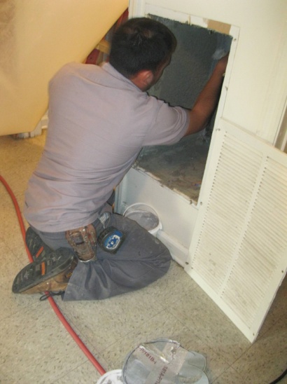
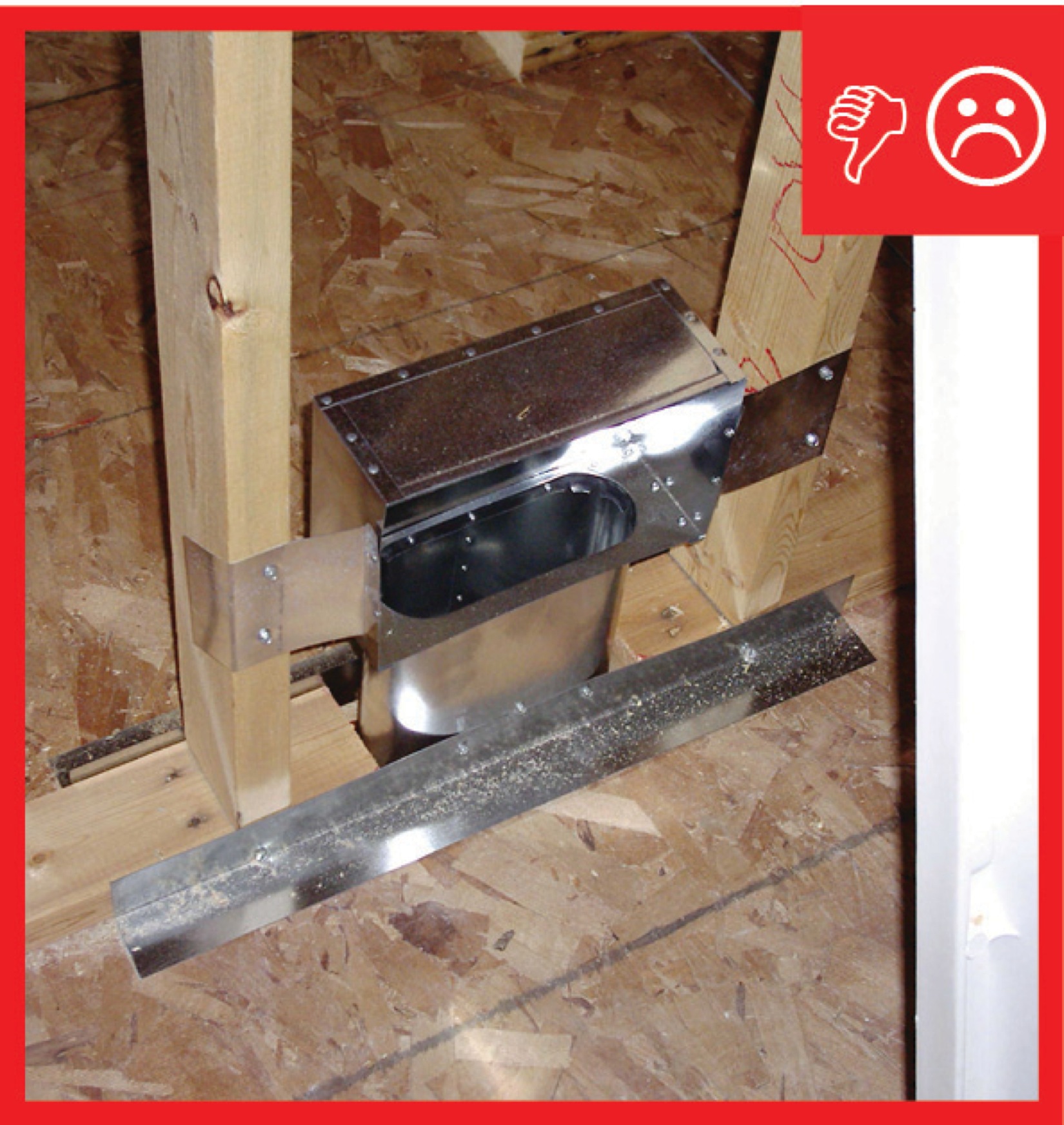
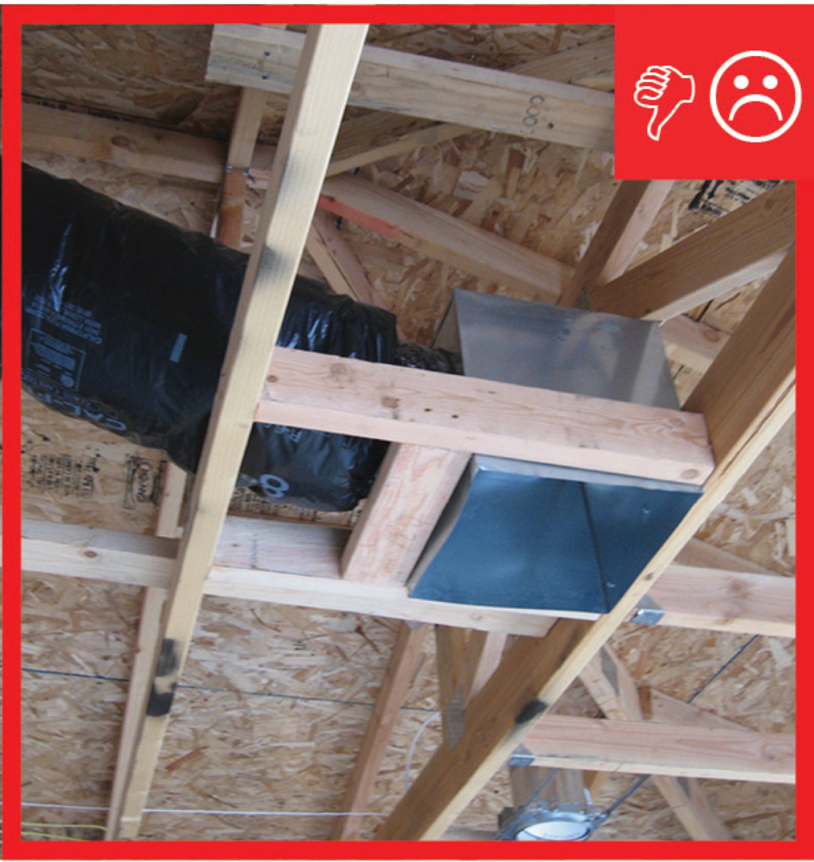
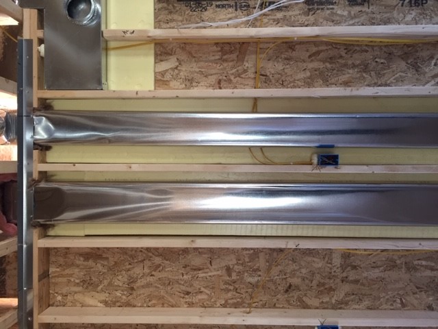
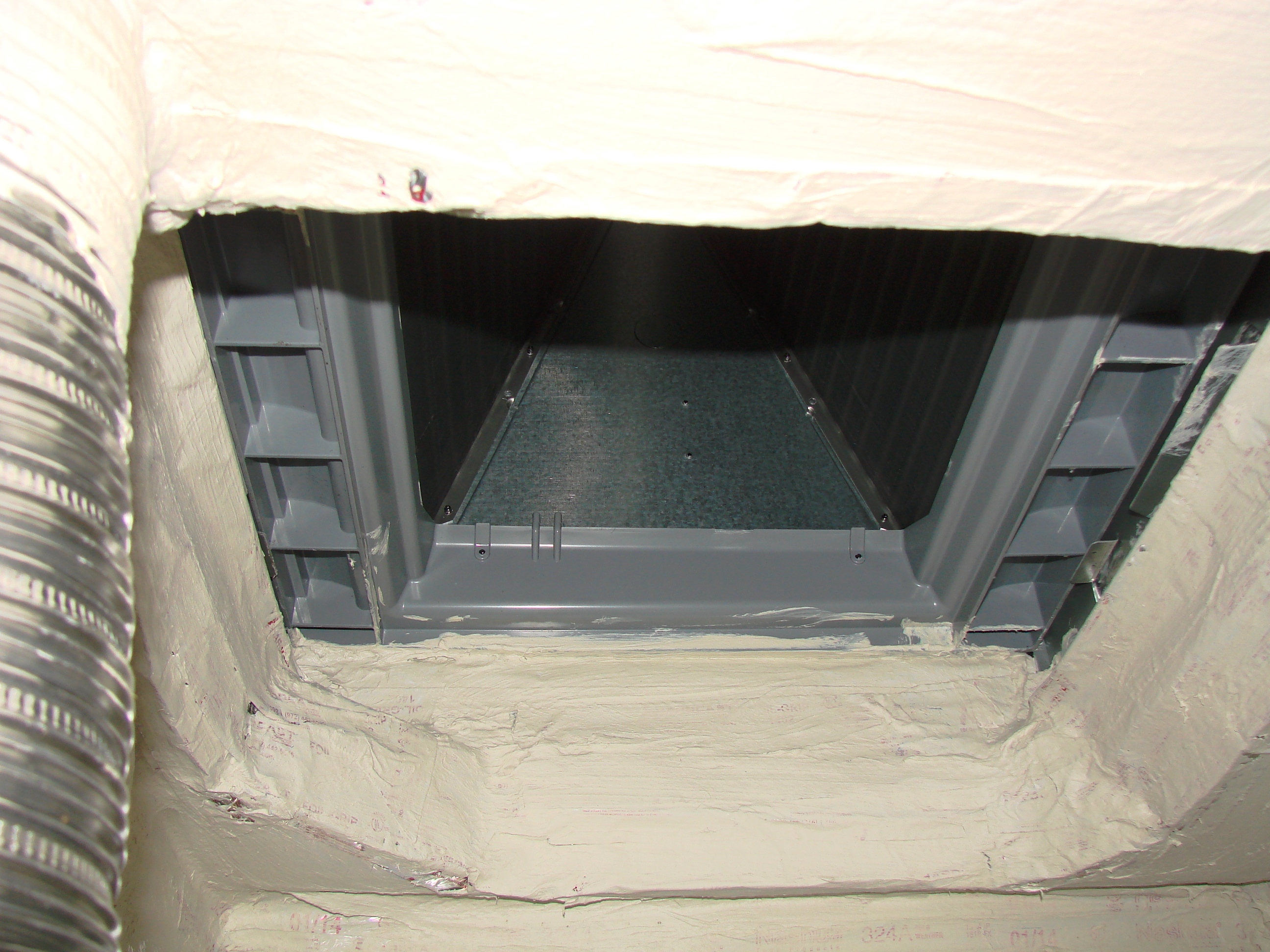
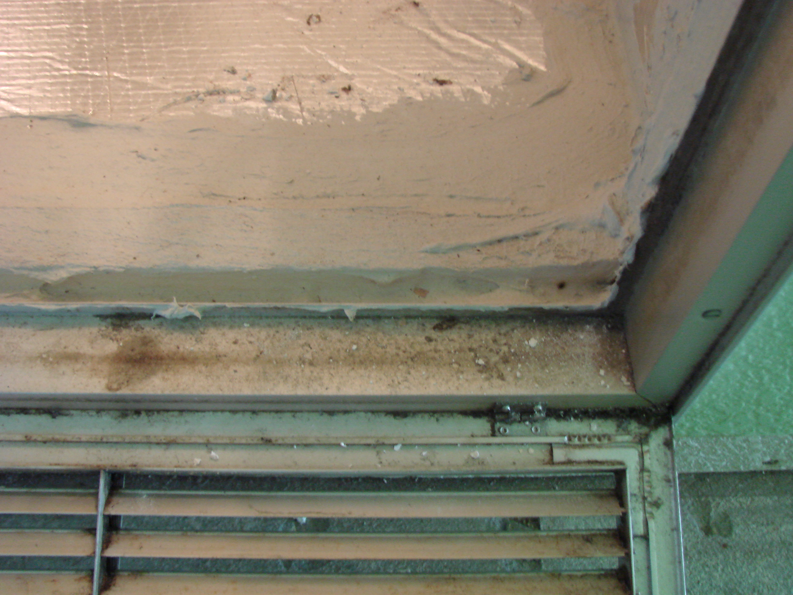
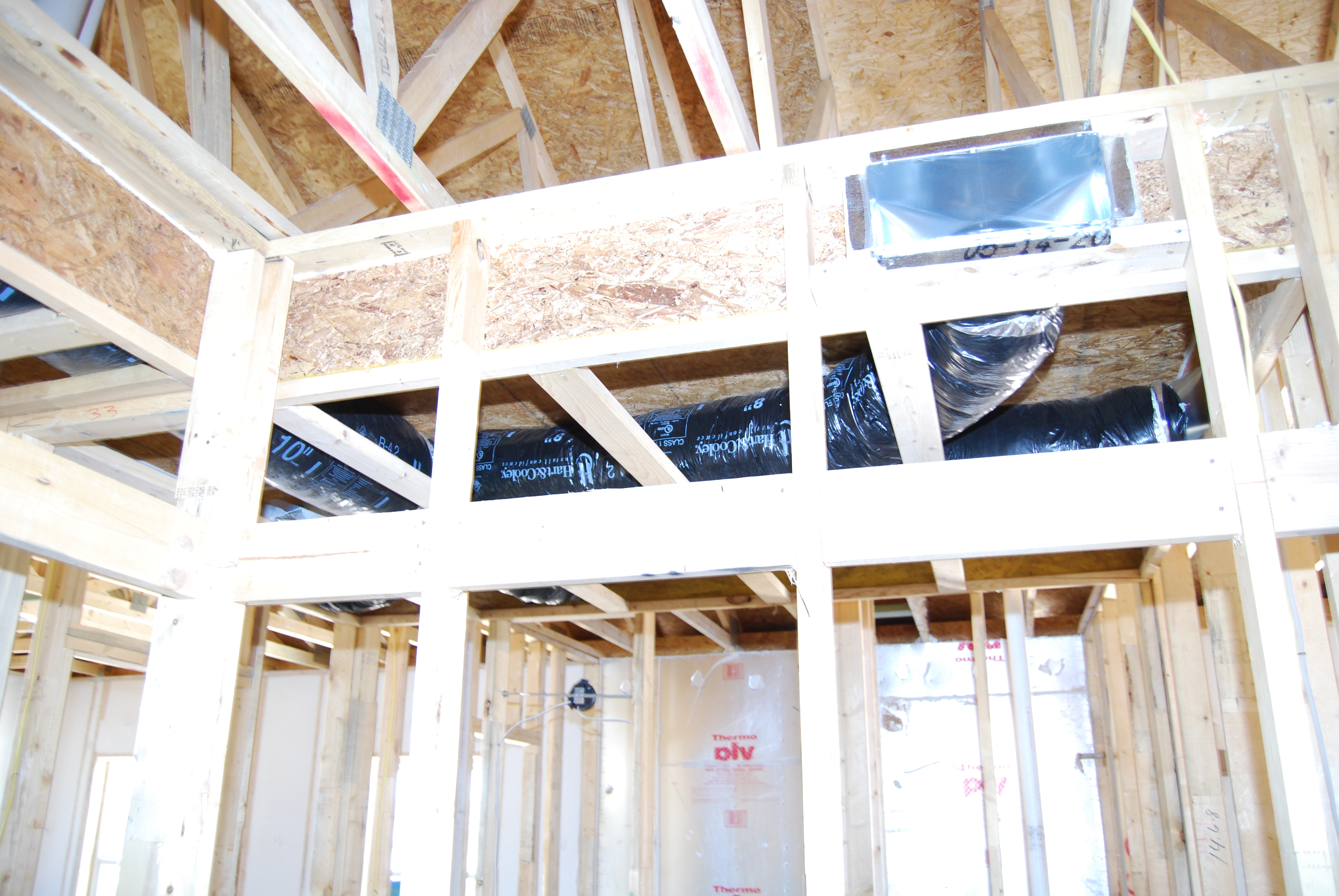
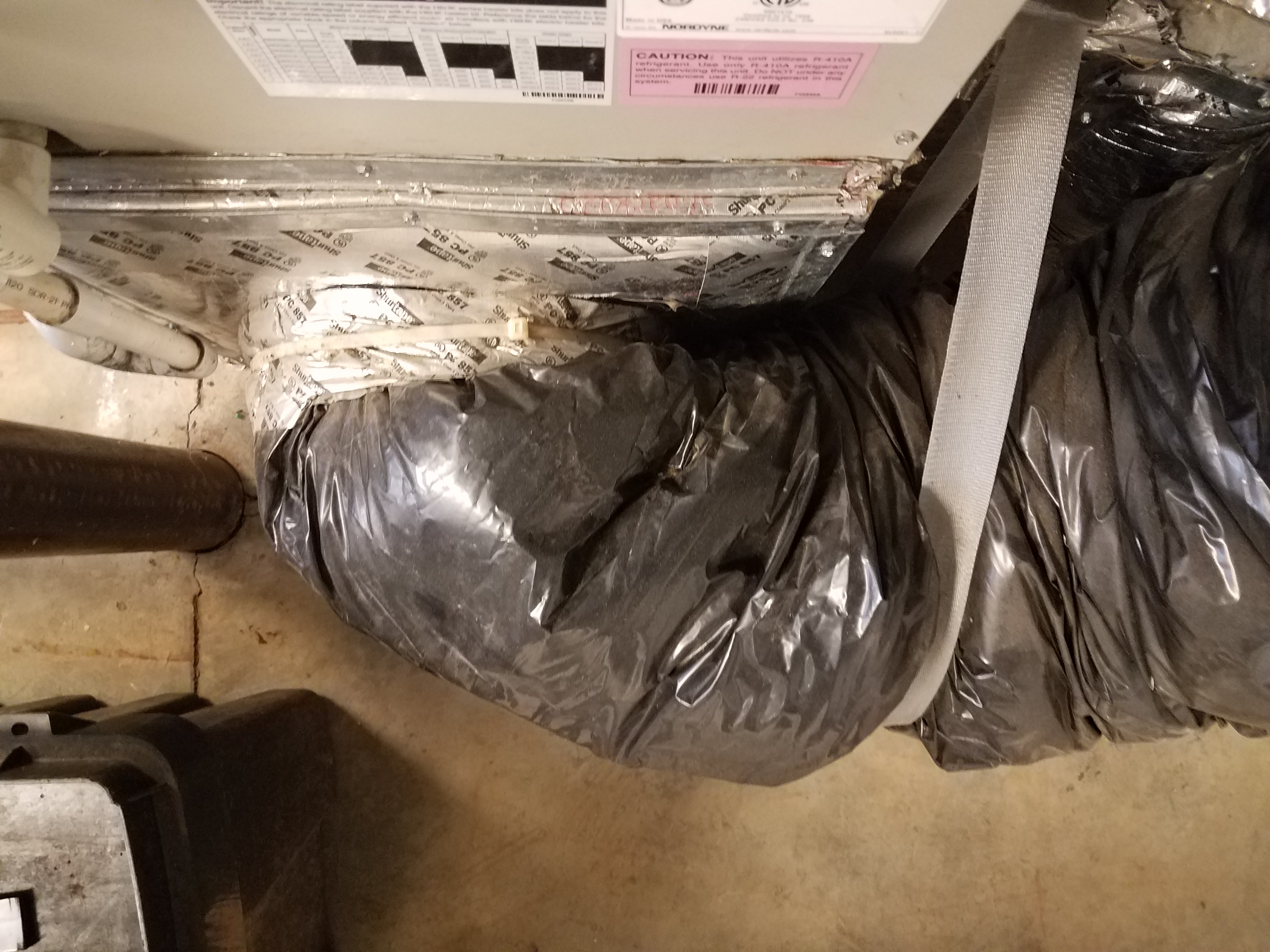
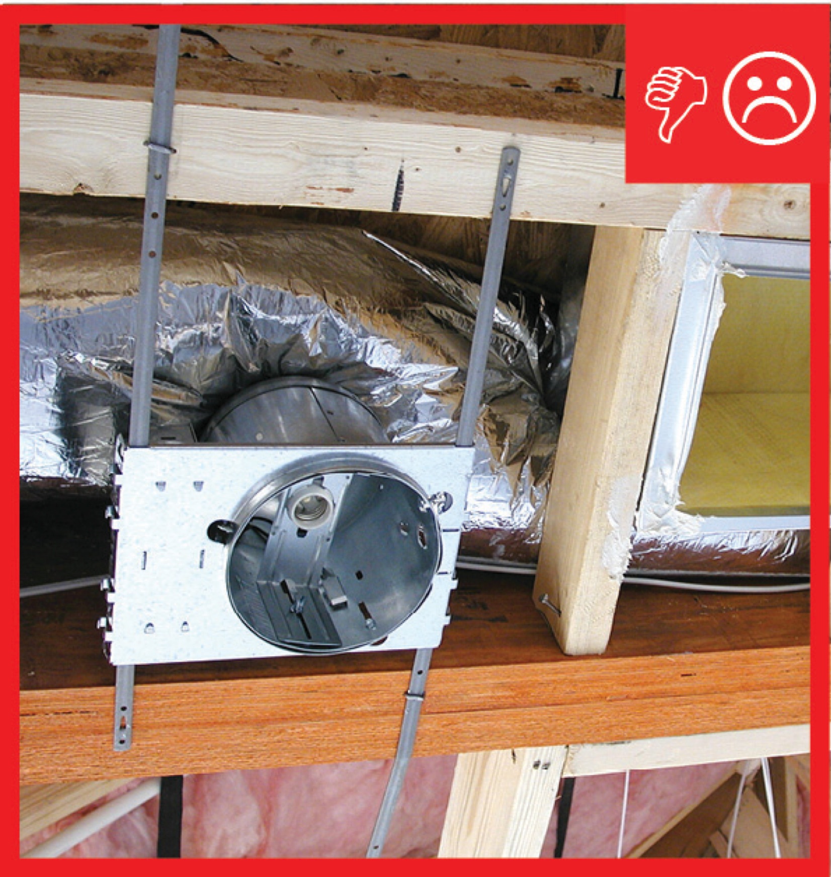
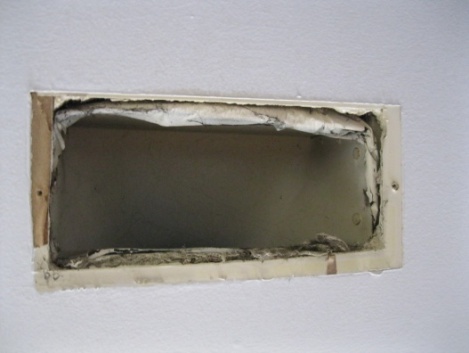
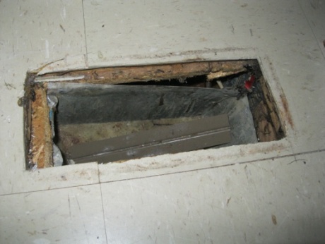
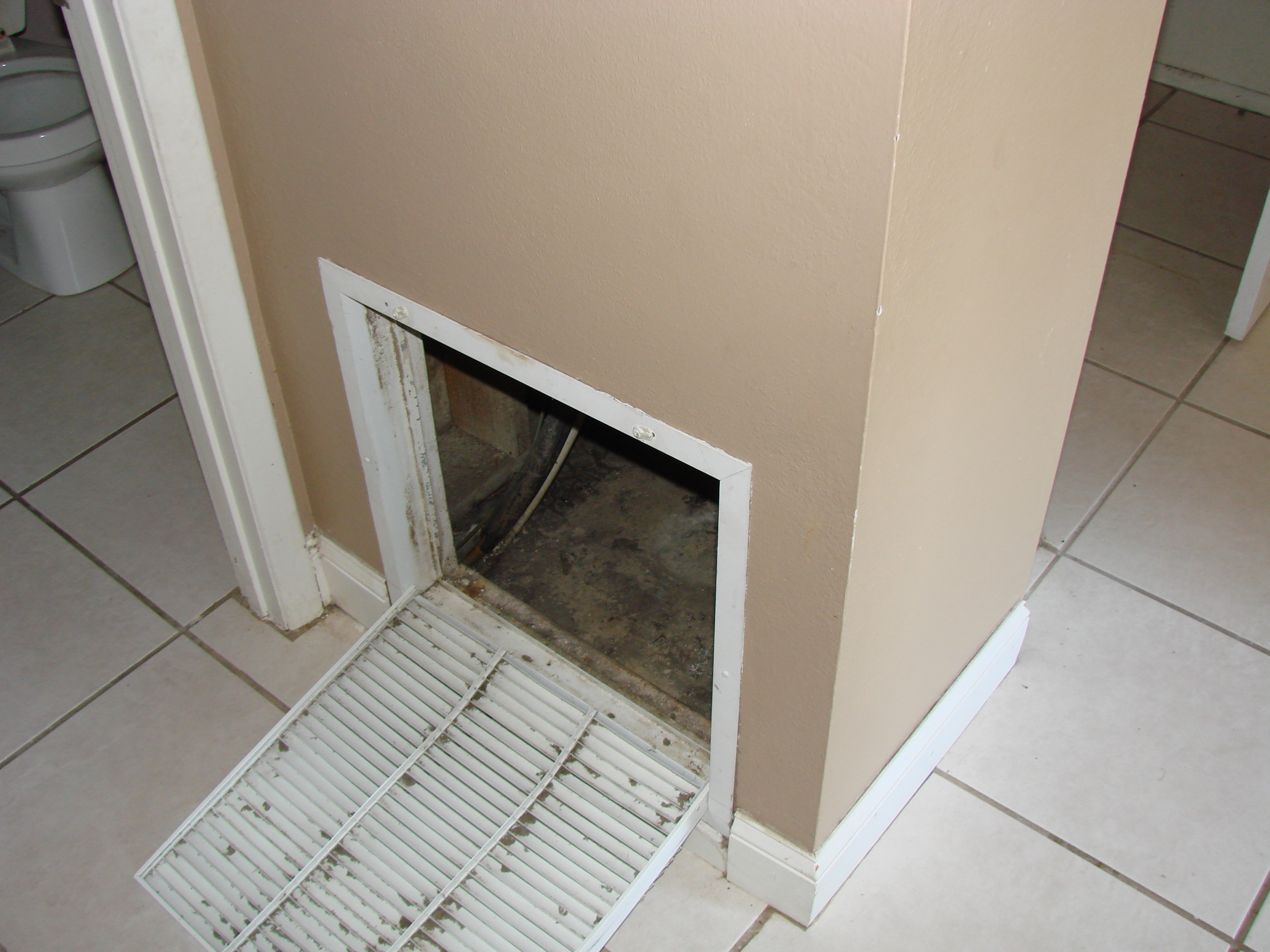
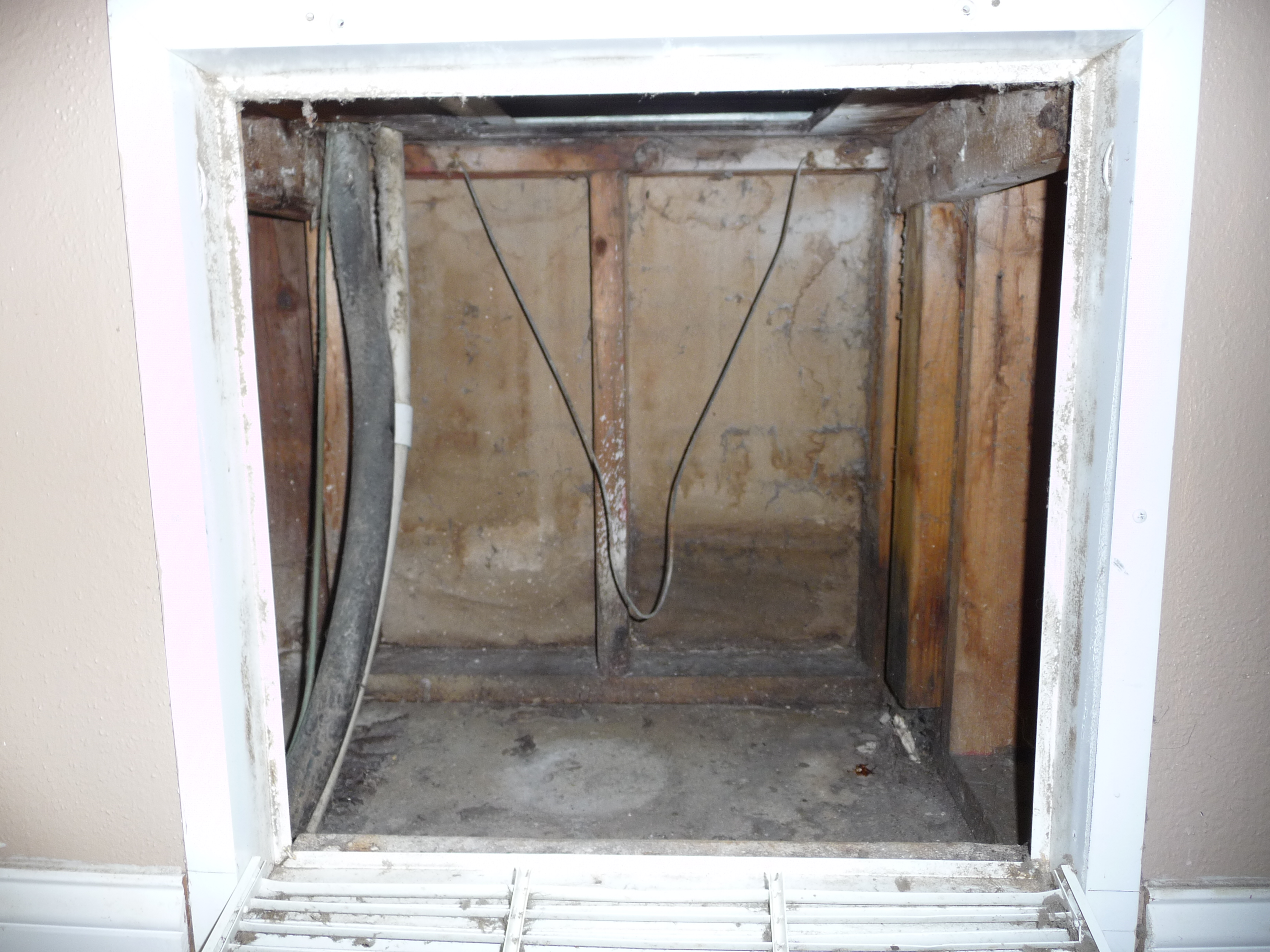
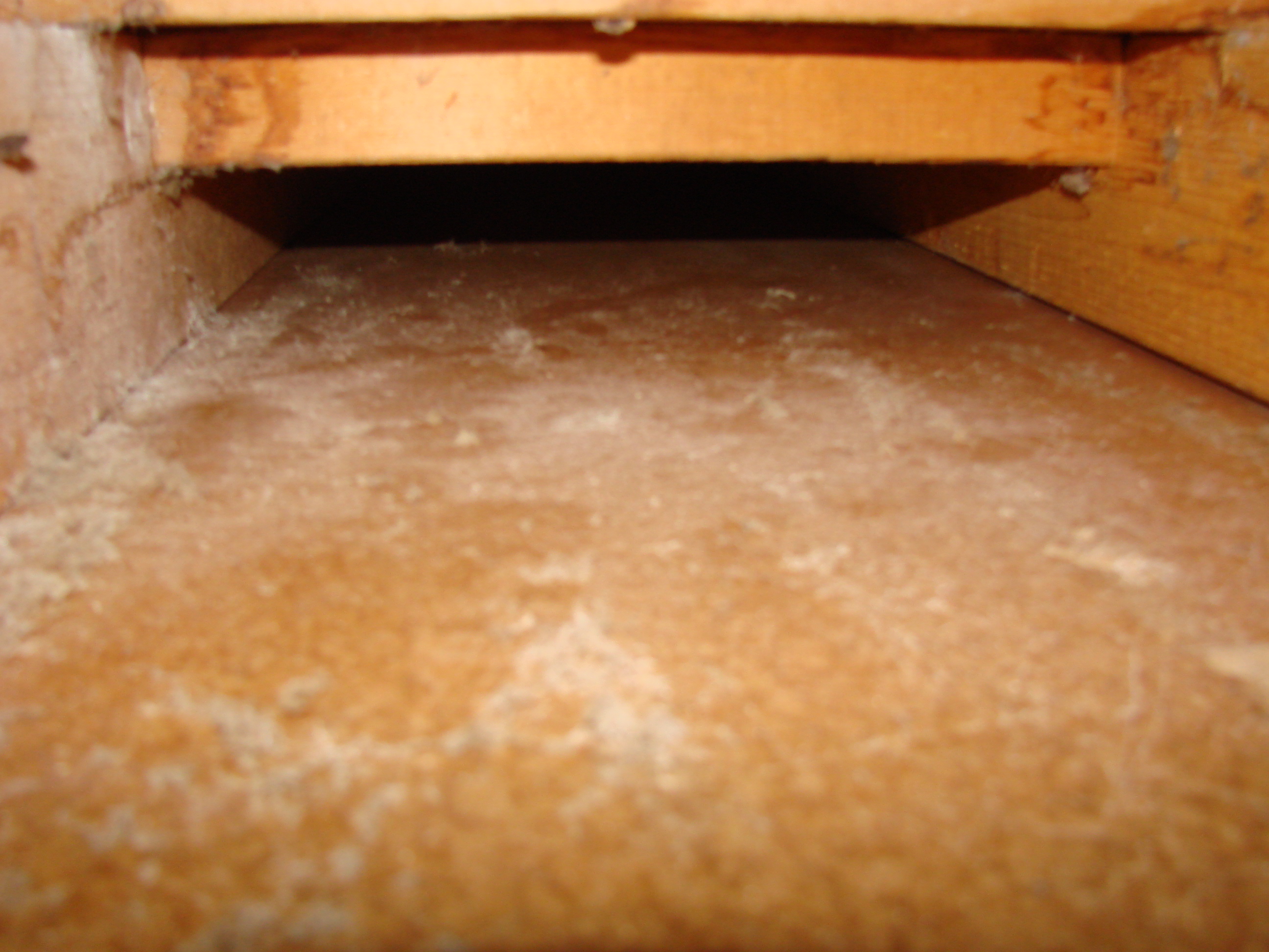
Cavity used for return is not insulated and is not air sealed, which will pull in air from outside
Image
Image
Image
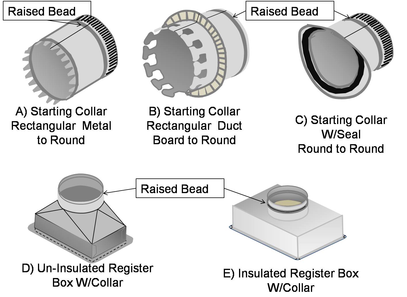
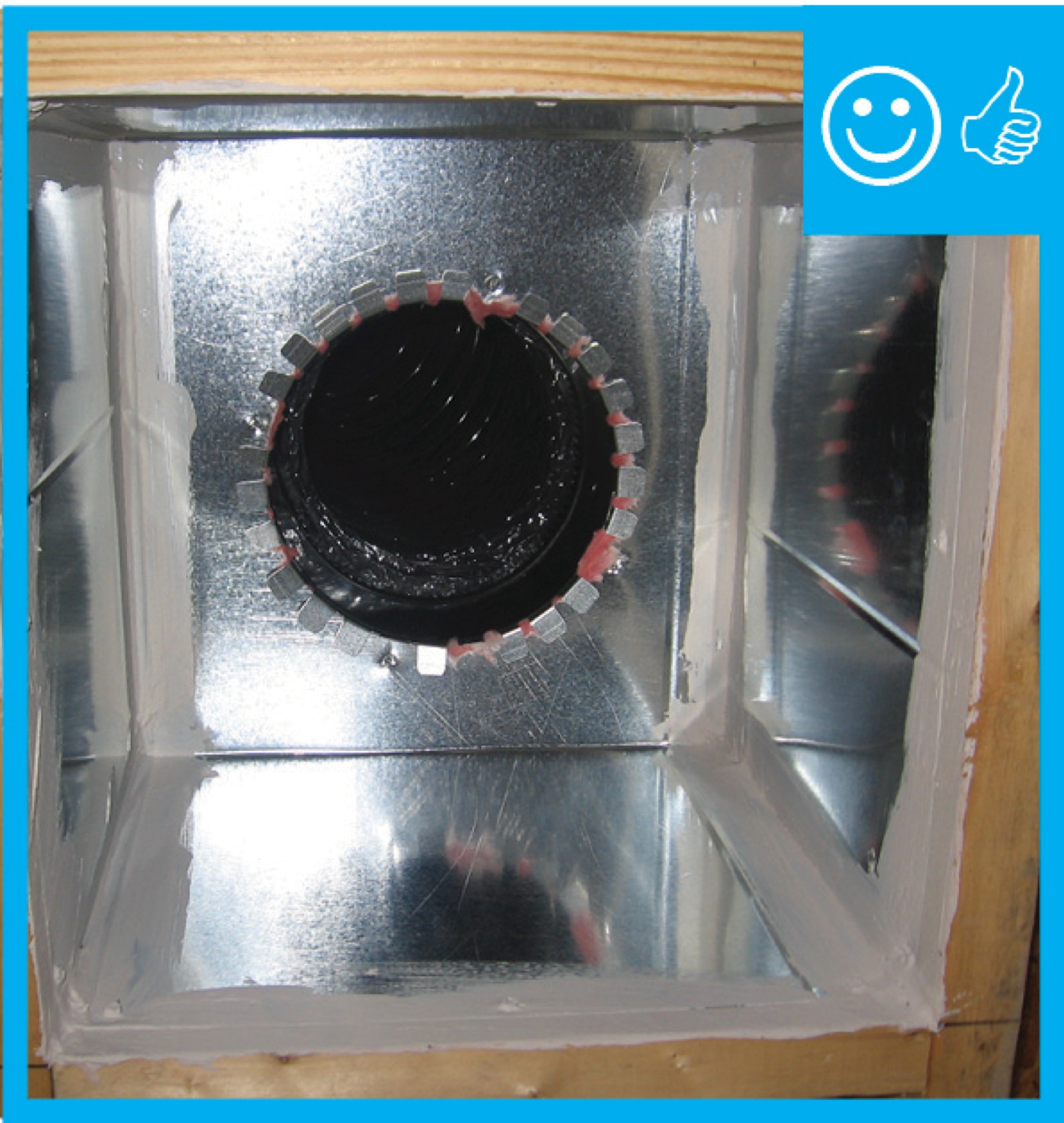
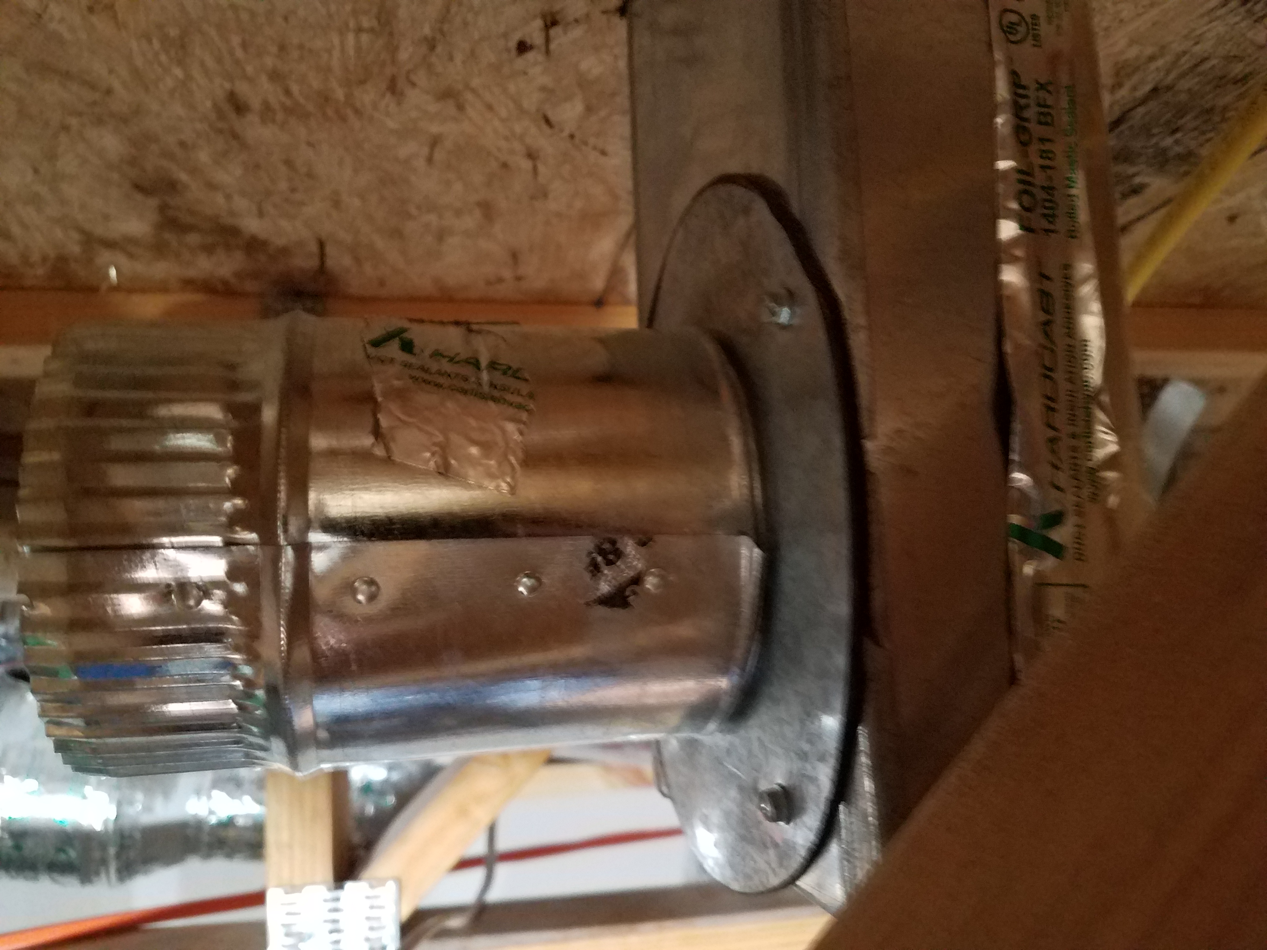
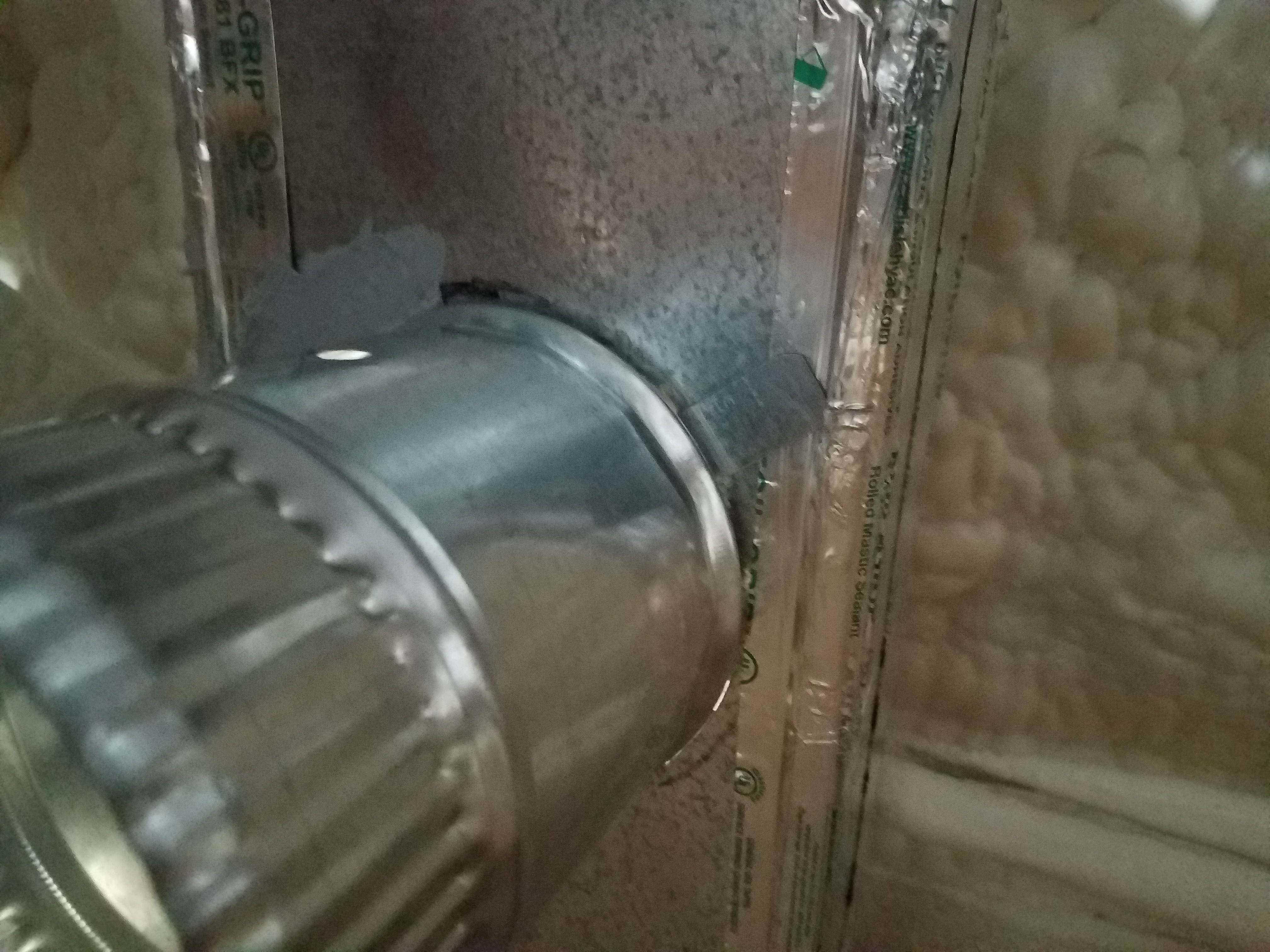
Collars that are specifically made for flexible duct have a raised bead to prevent the duct from slipping off
Image

Image
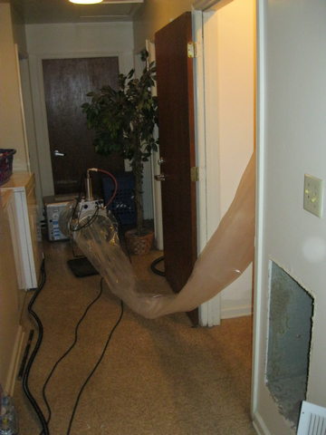
Connect the plastic application tunnel from the injection equipment to the supply plenum.
Image
Image
Image
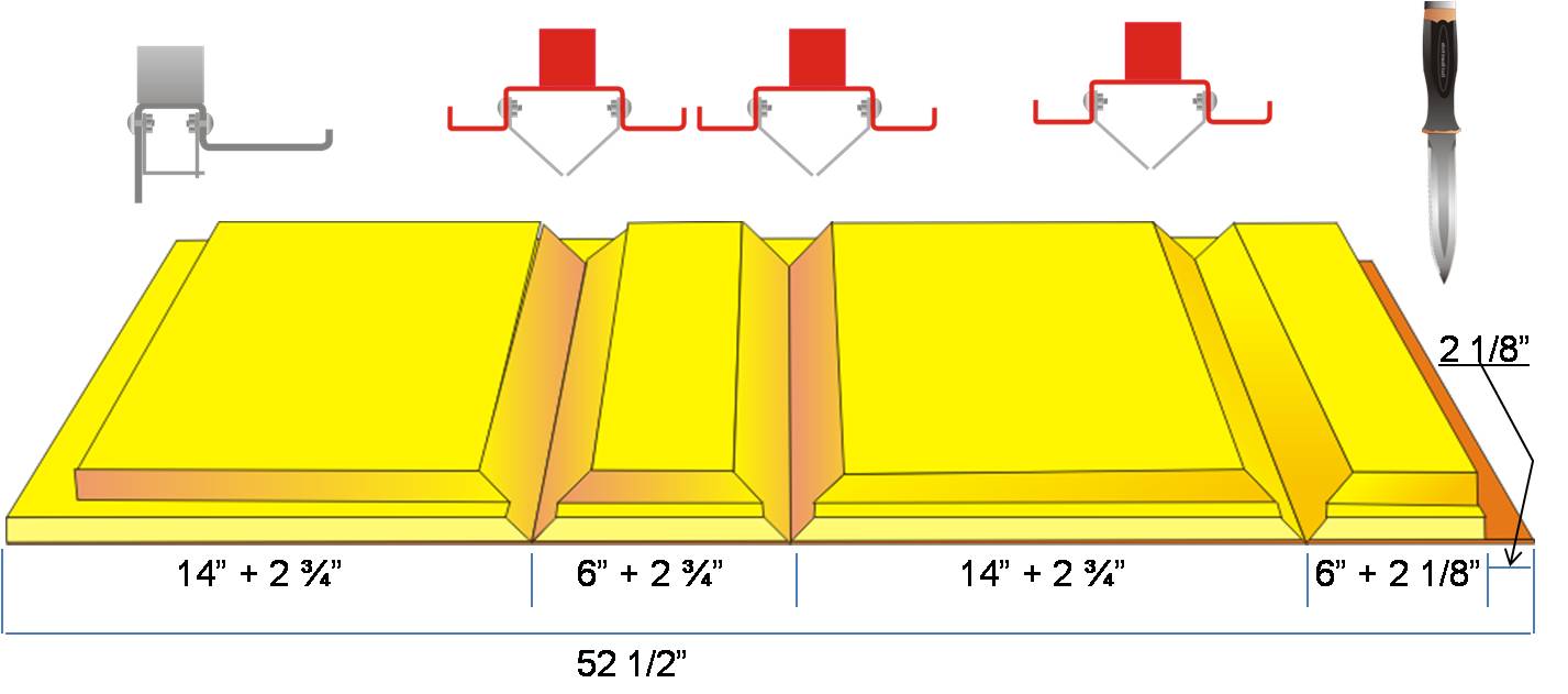
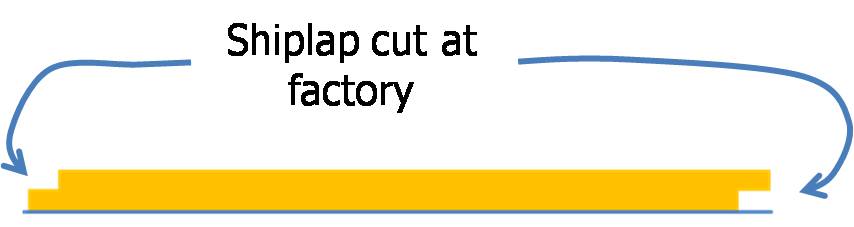
Cut fiber board with a red V-groove tool and a gray shiplap tool to create mitered corners and a shiplapped edge for duct sections
Image
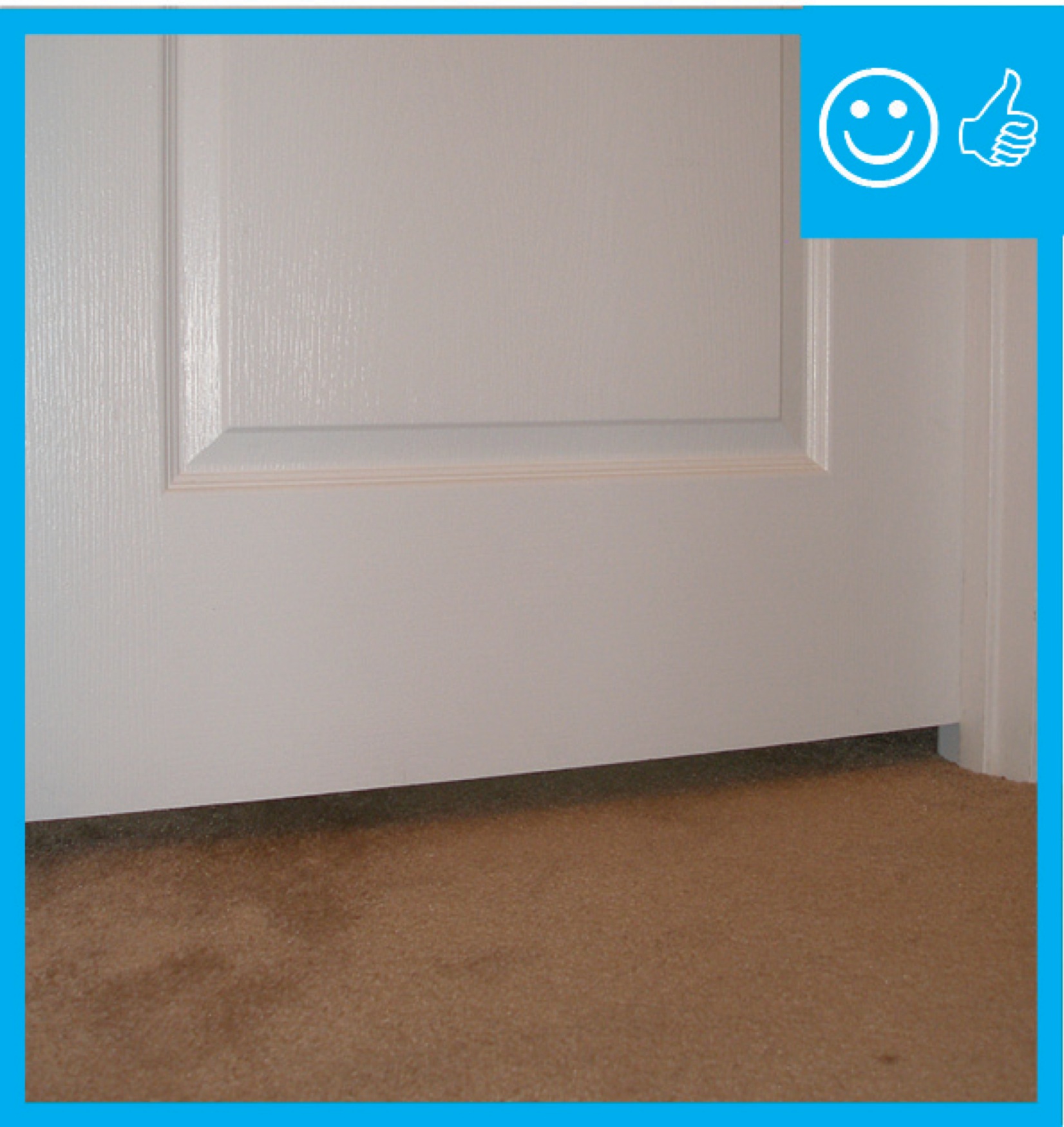
Door has been undercut to allow for specified amount of air flow therefore contributing to pressure balancing
Image
Image
Image
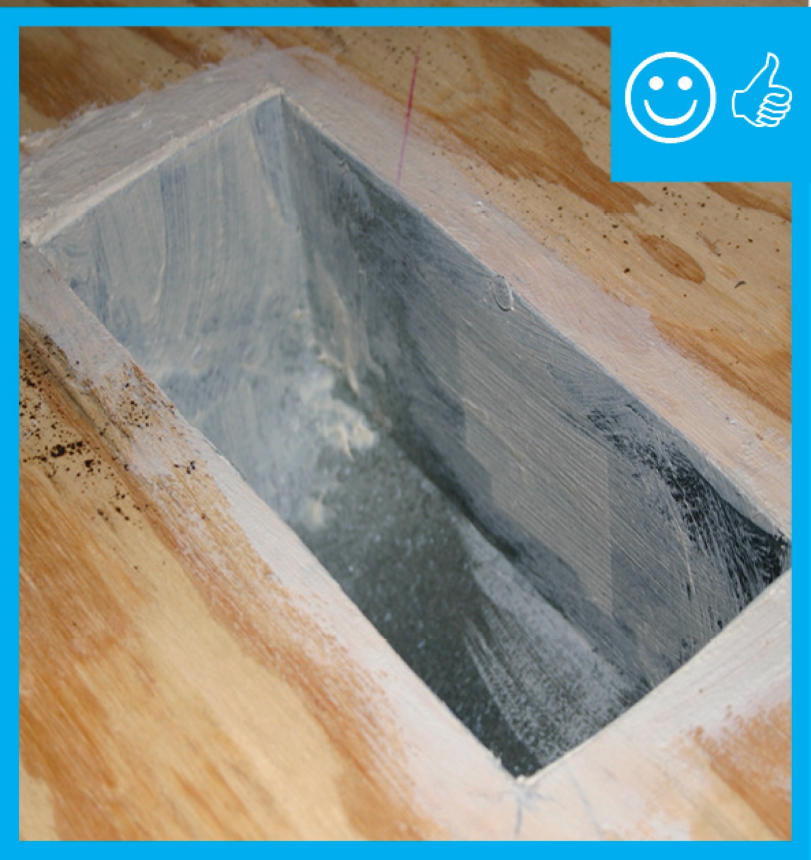
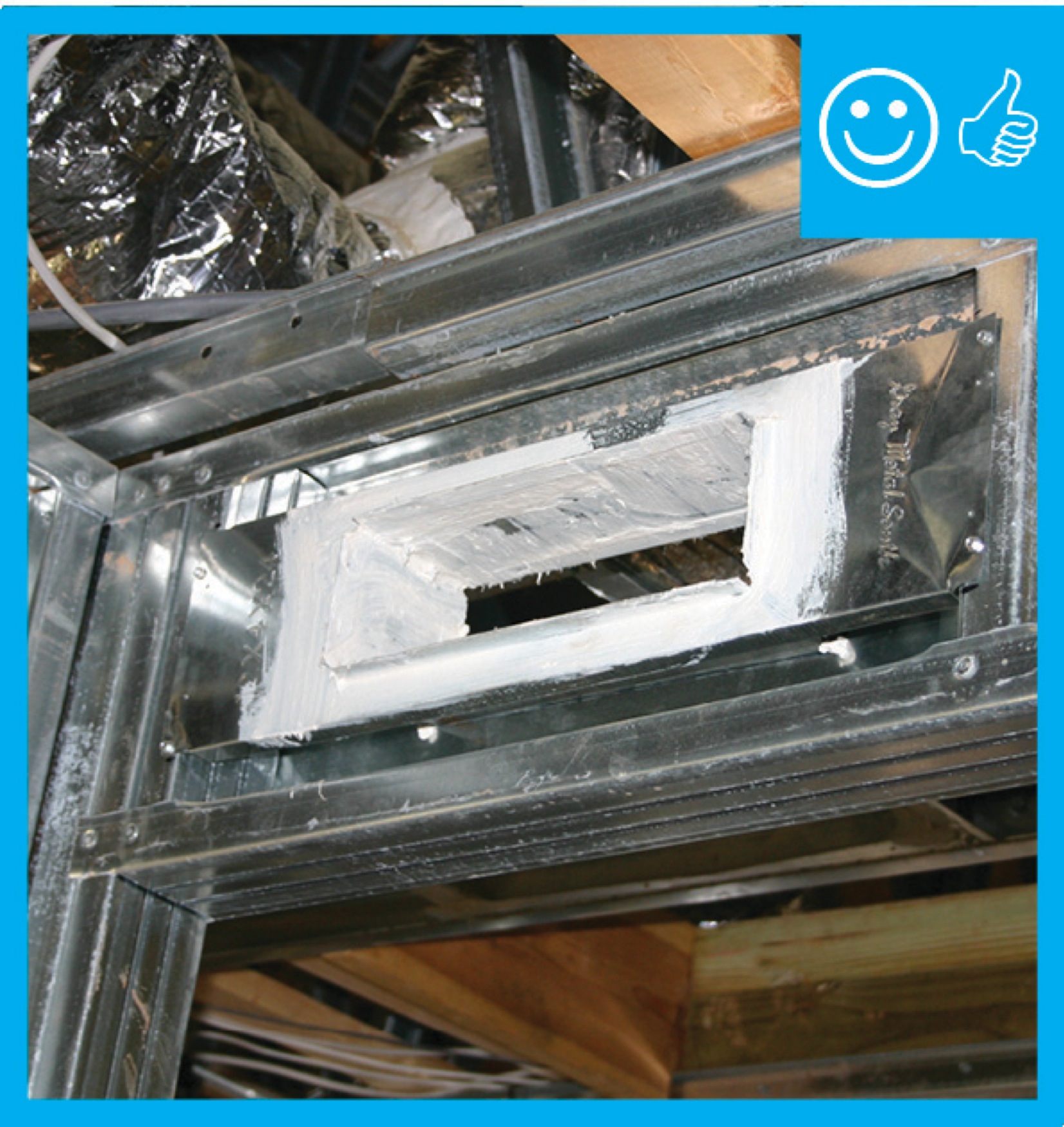
Duct boot is air sealed to ceiling by covering the seam with fiberglass mesh tape and mastic
Image
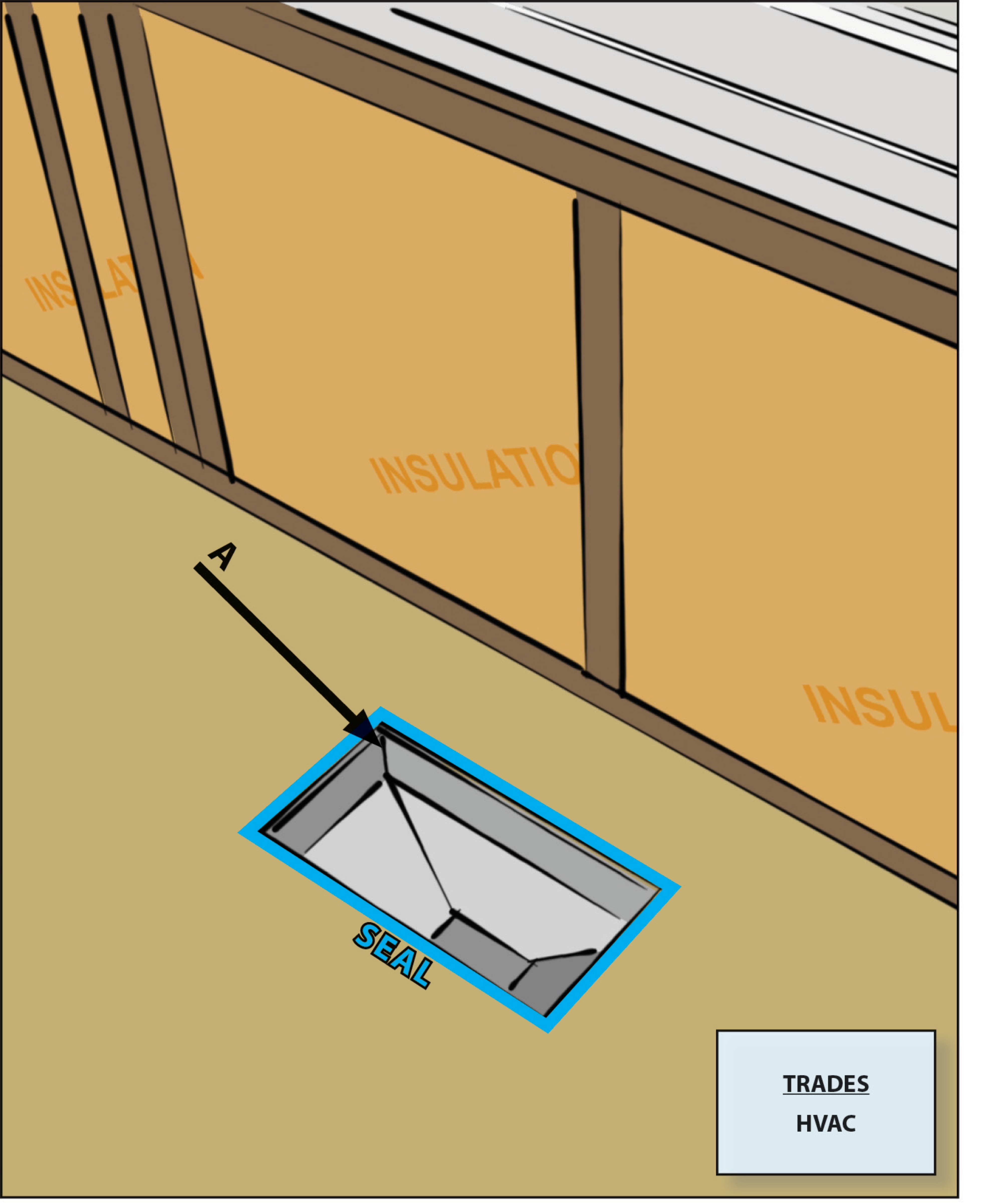
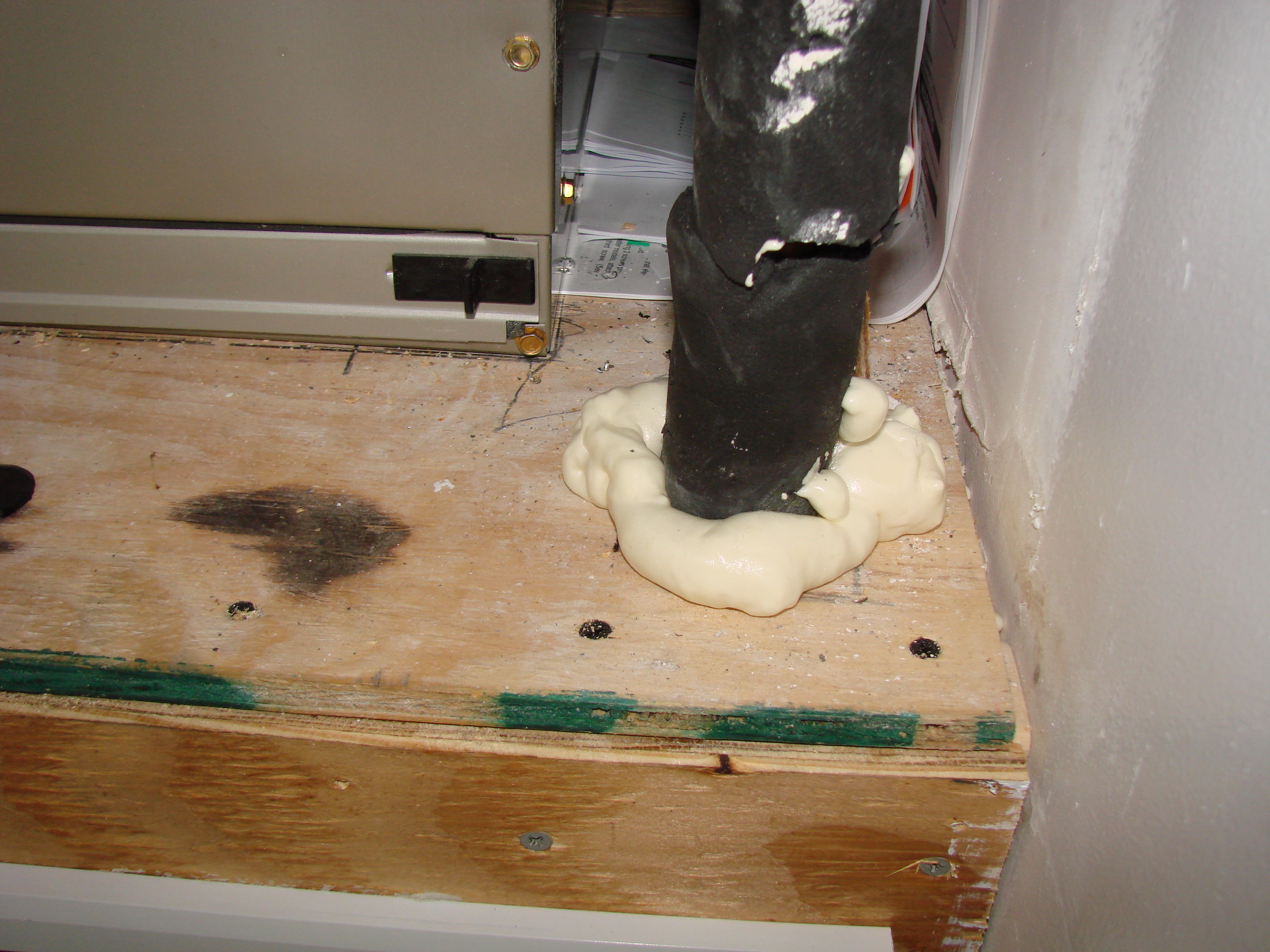
Duct boots sealed to floor, wall, or ceiling using caulk, foam, mastic tape, or mastic paste
Image
Image
Image
Image
Image
Image
Image
Image
Image
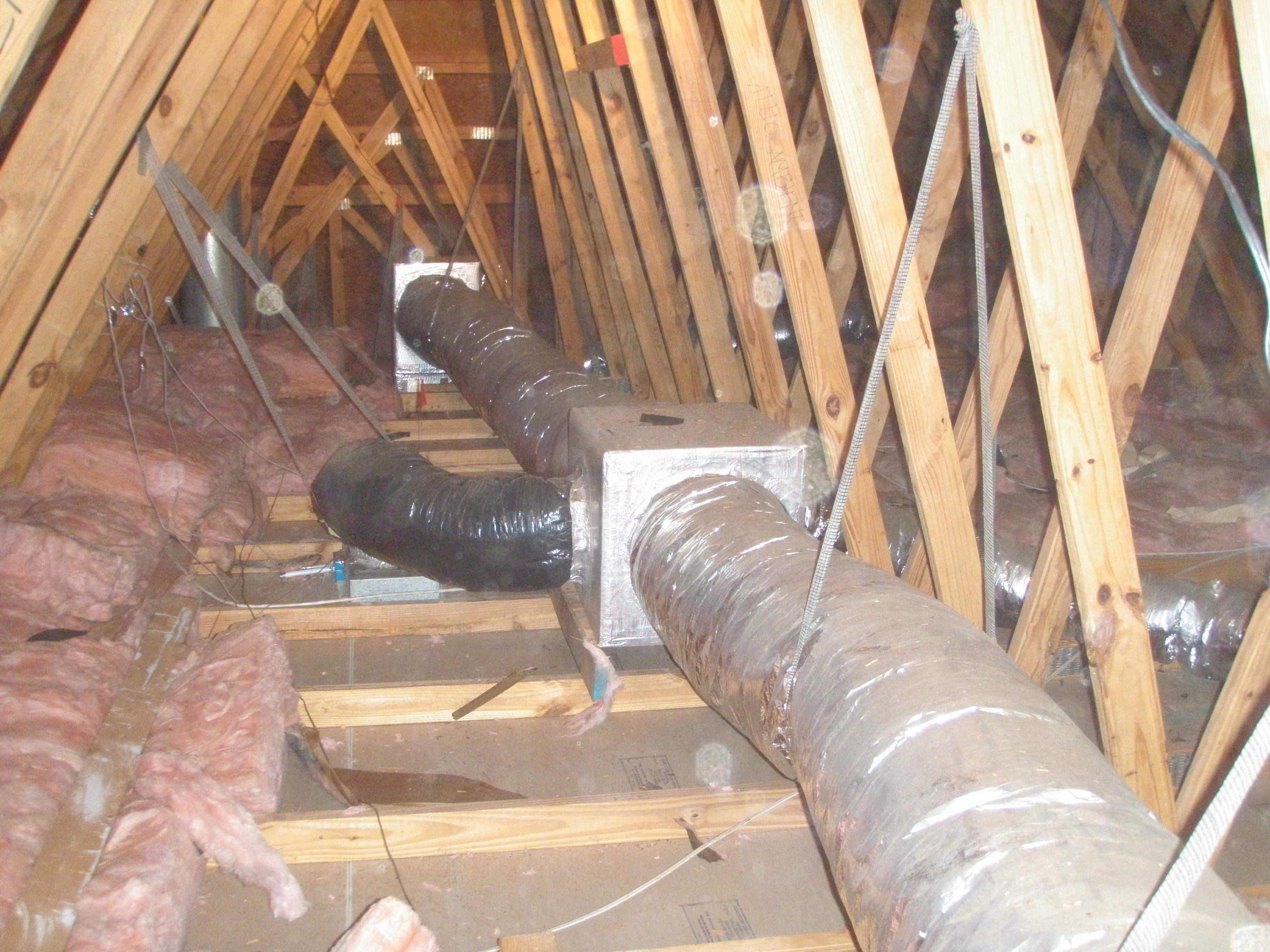
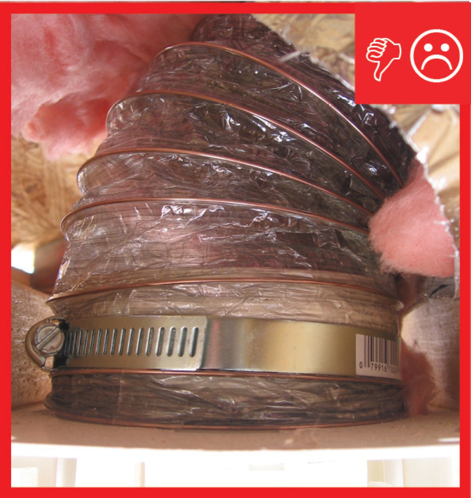
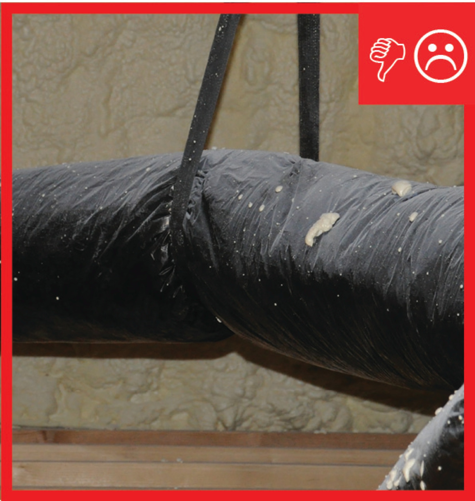
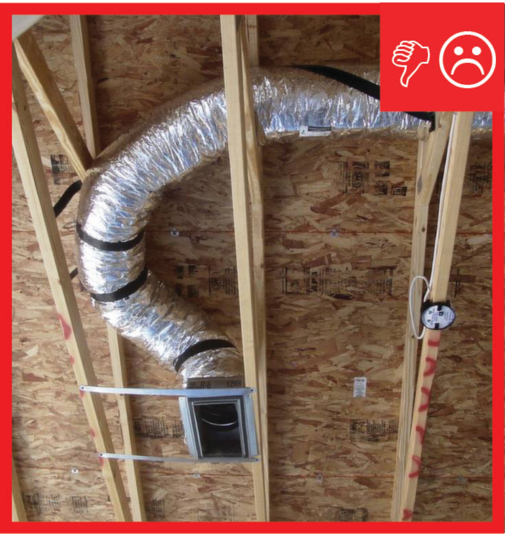
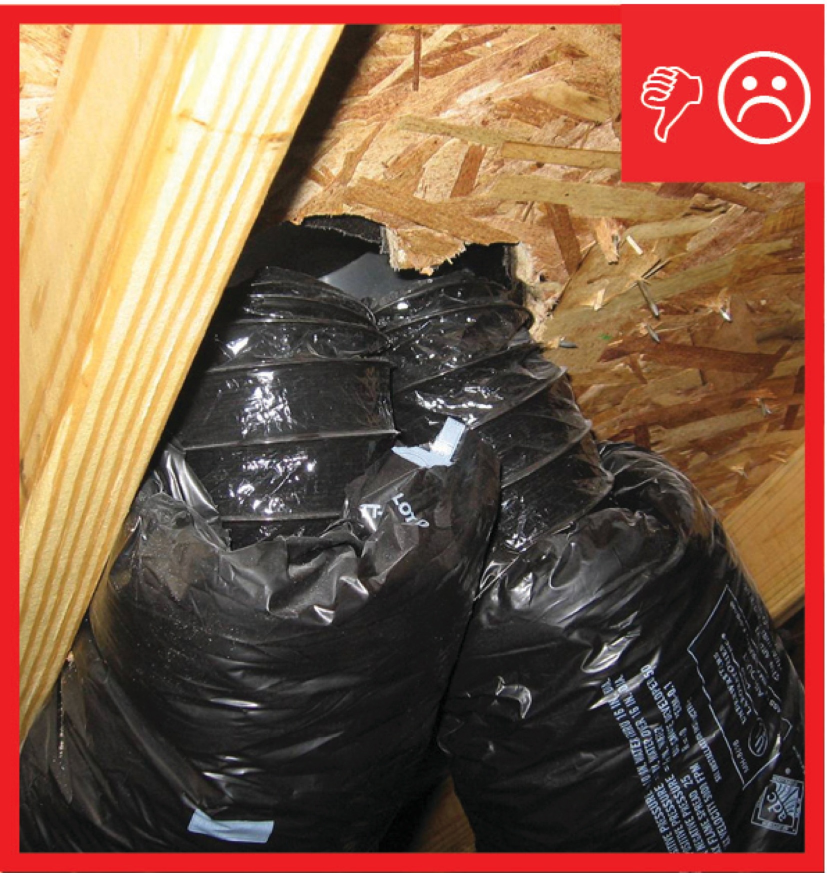
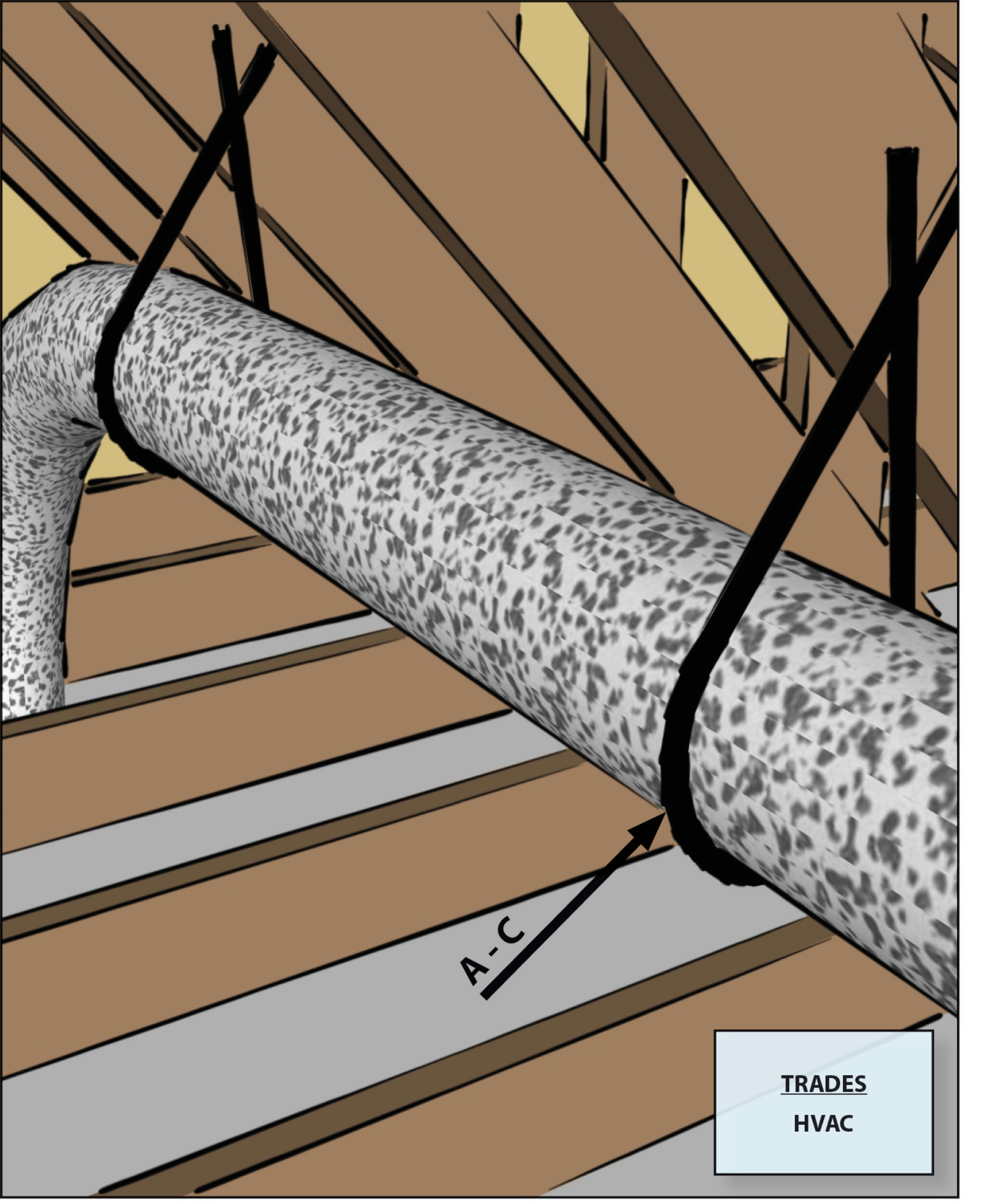
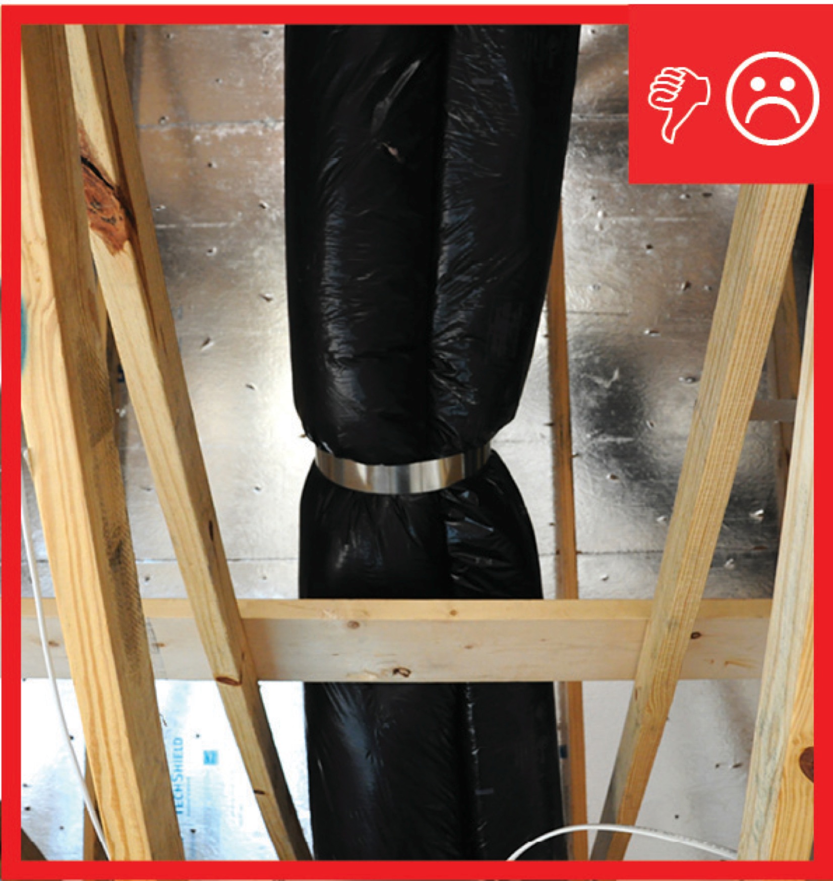
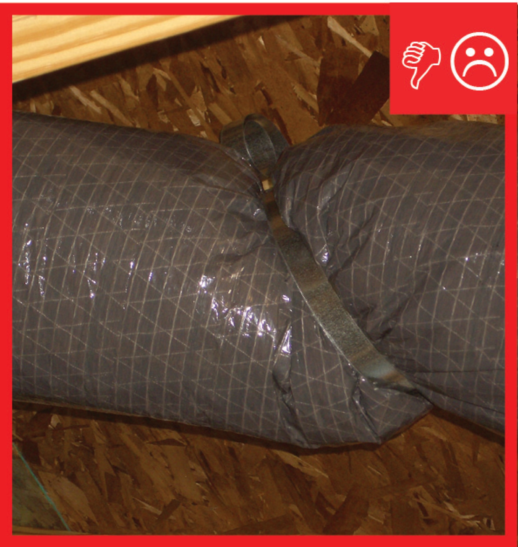
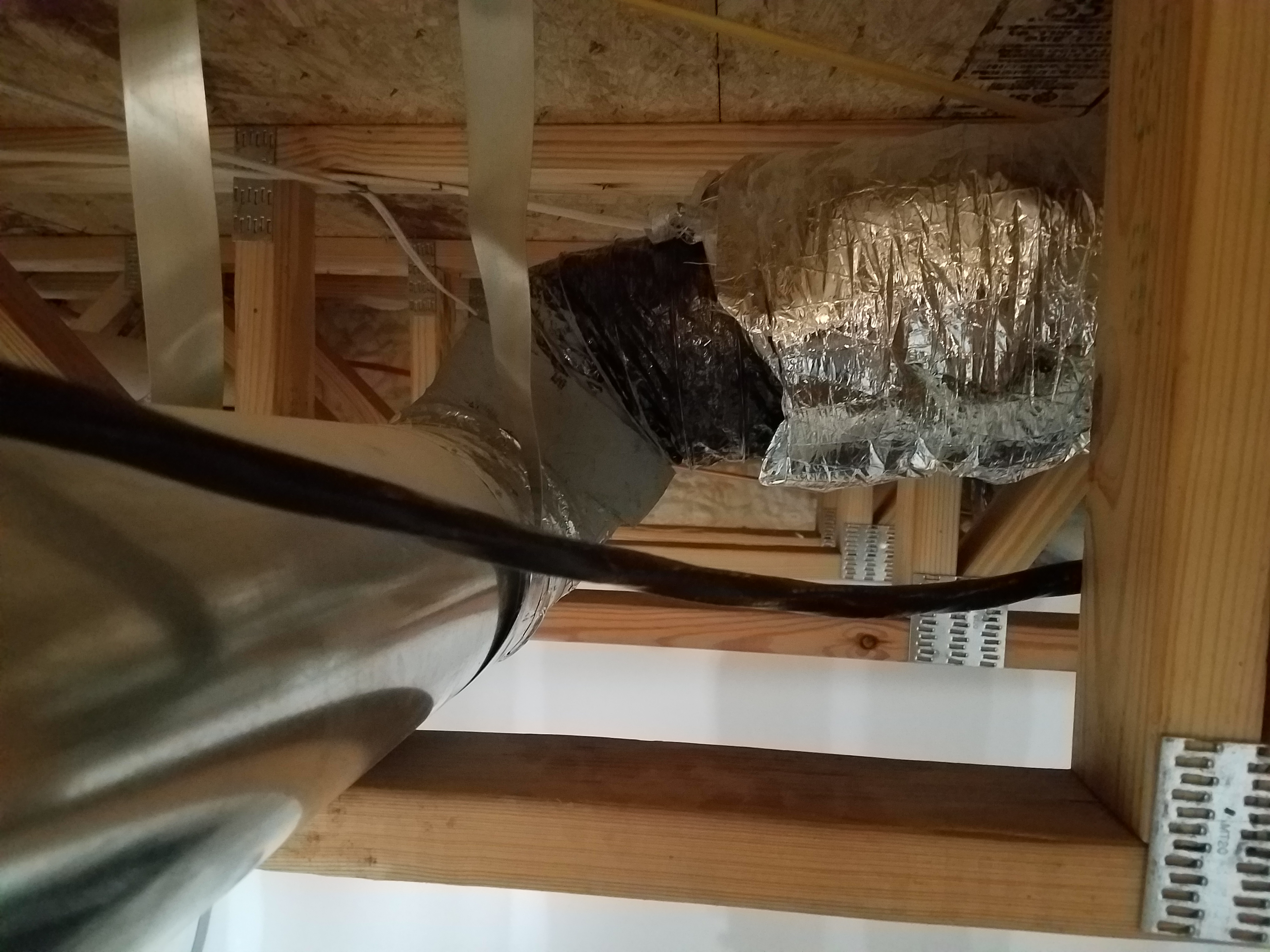
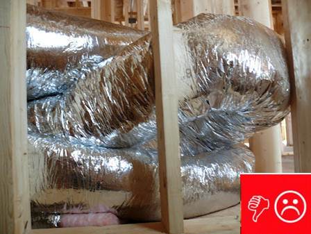
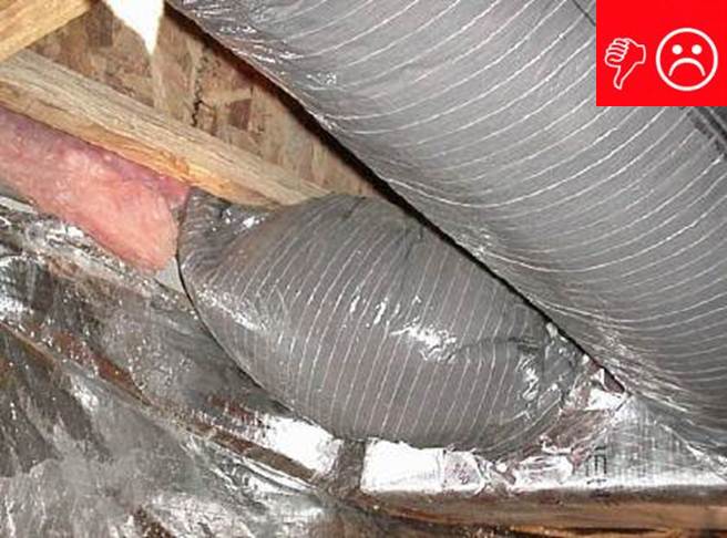
Duct lacks adequate support to carry the weight so the few straps are pinching the duct
Image
Image
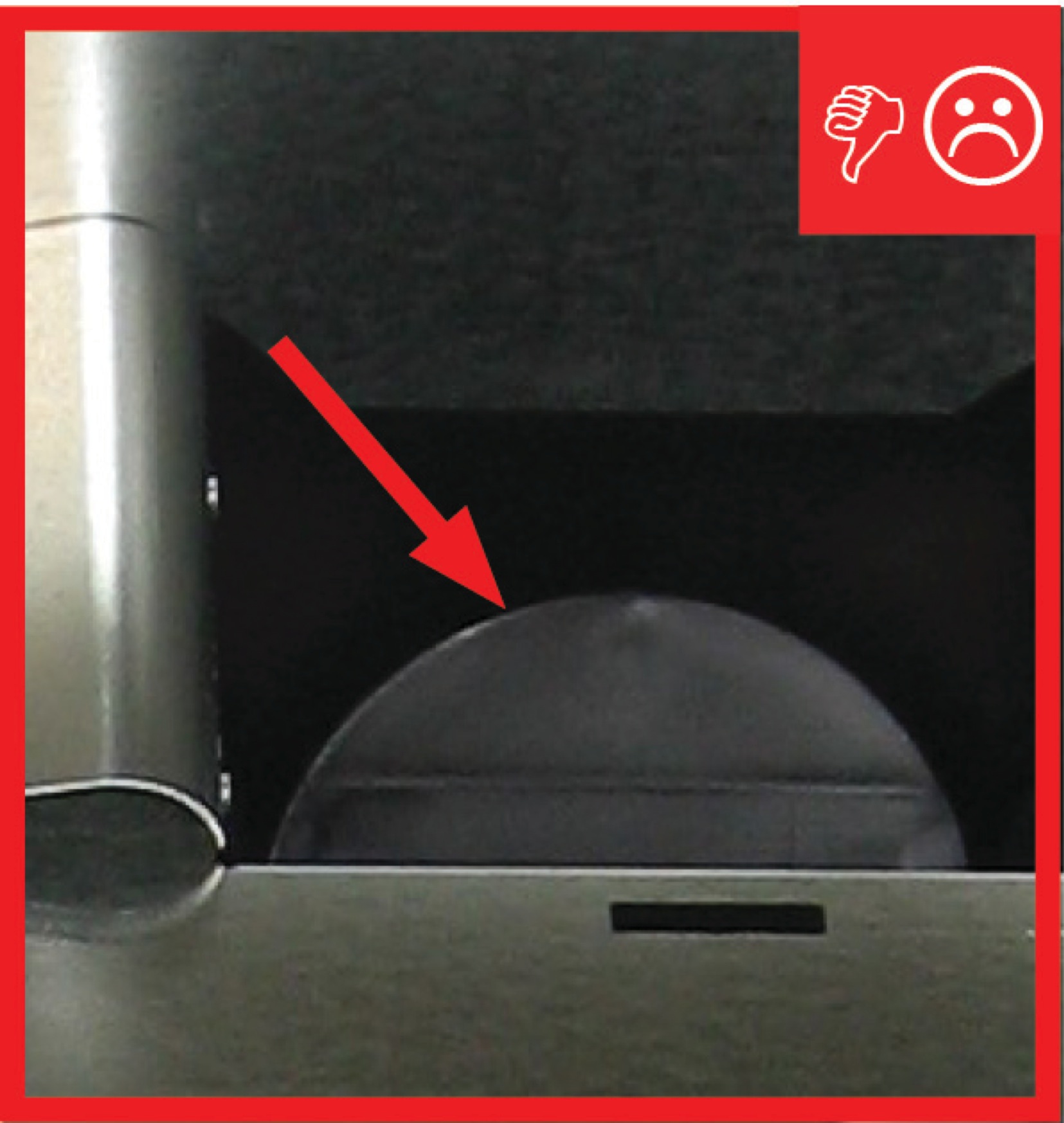
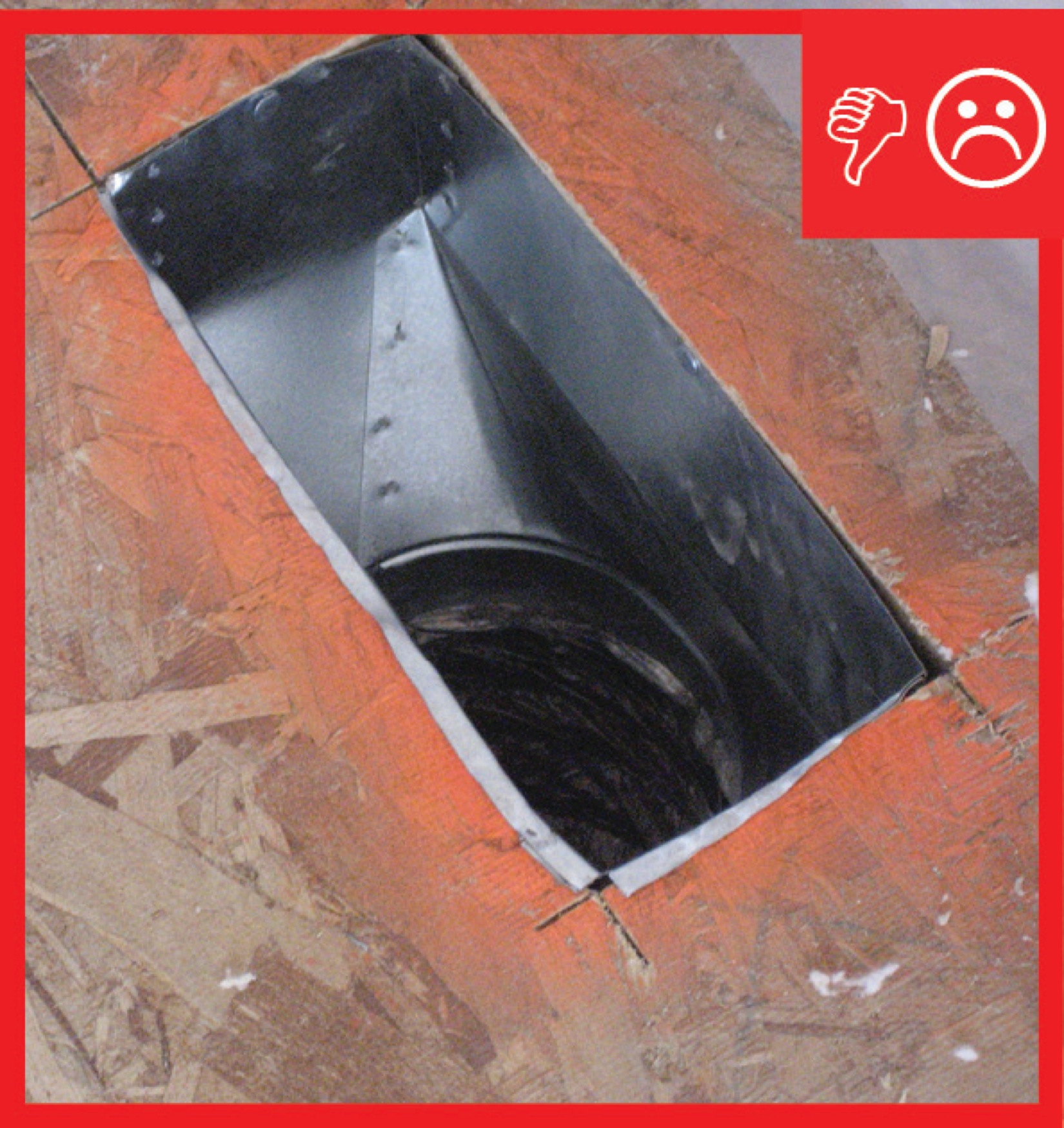
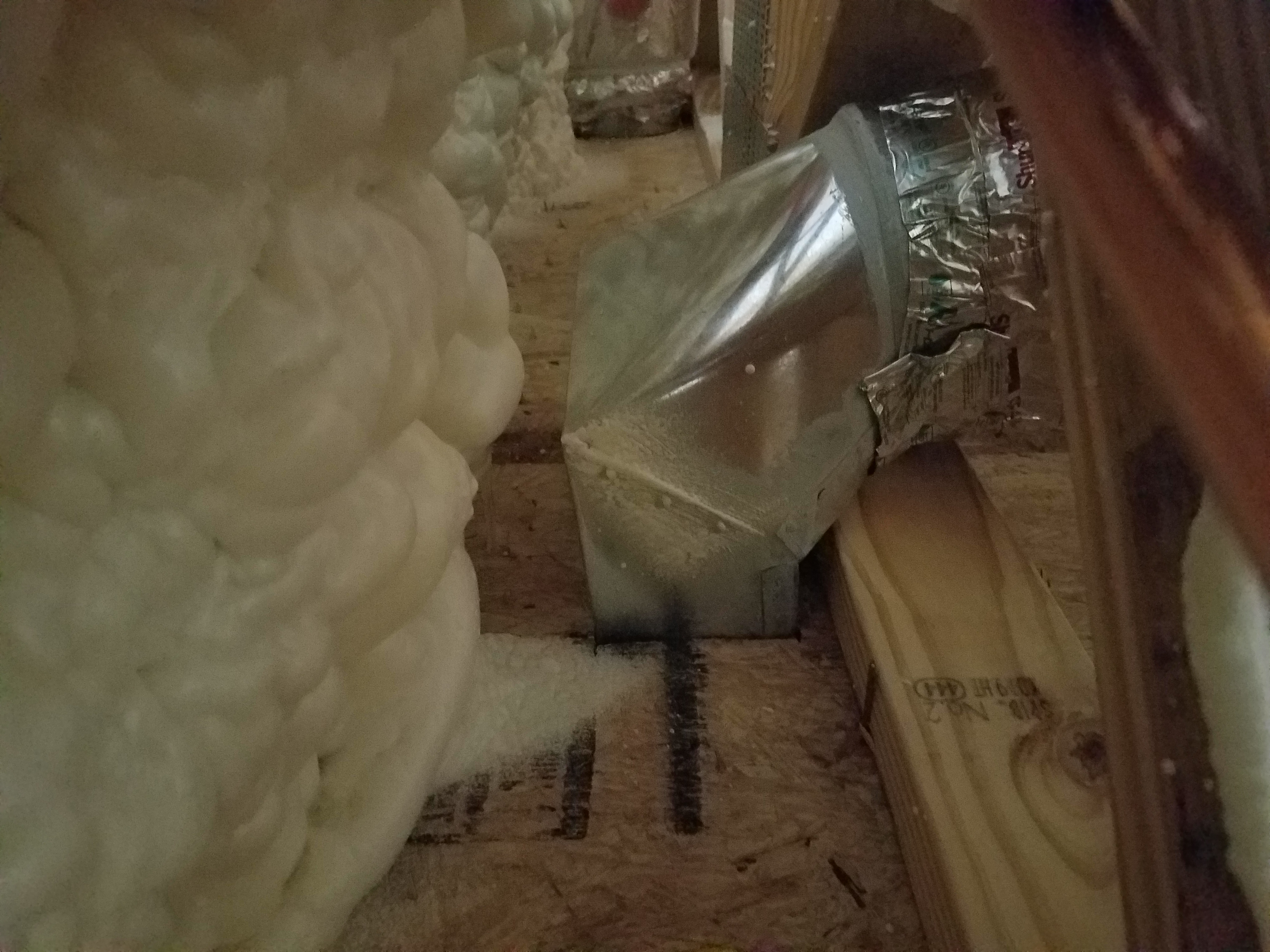
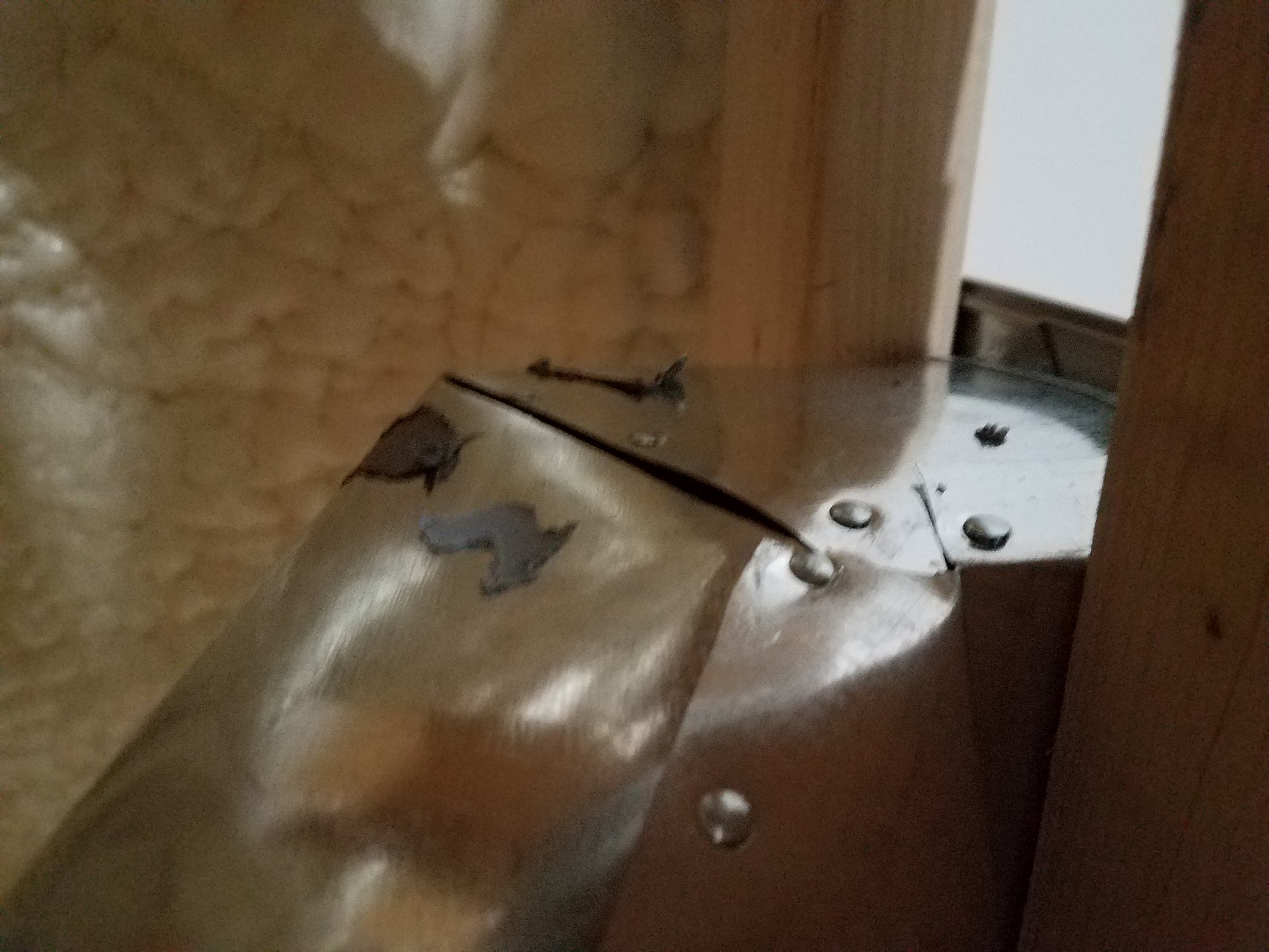
Duct to boot connection of jump duct not fastened and sealed
Image
Image
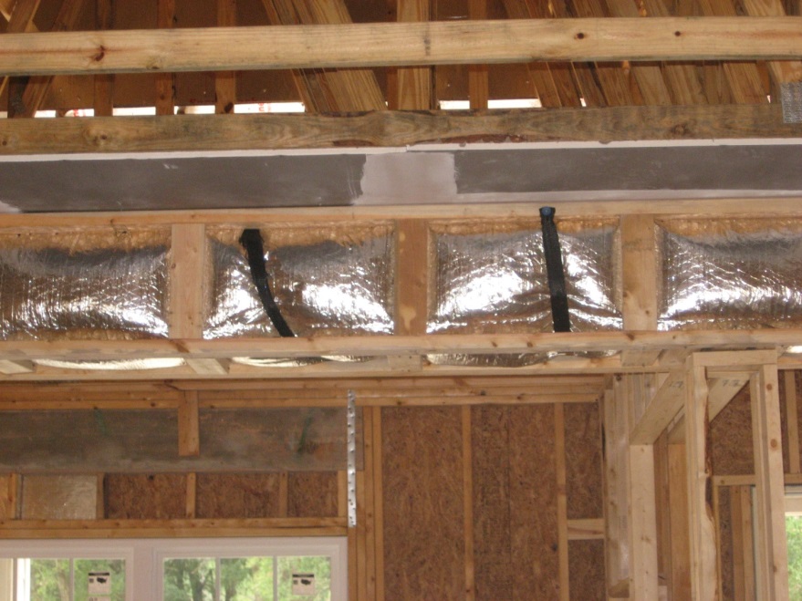
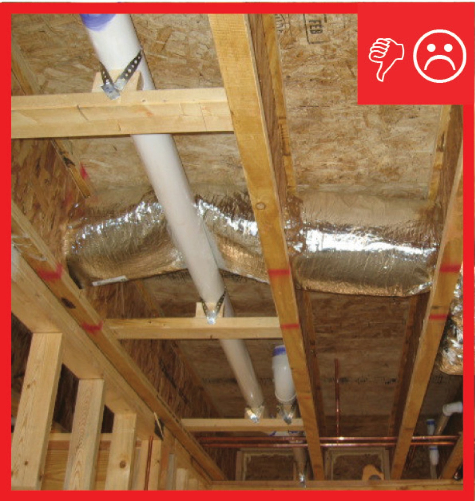
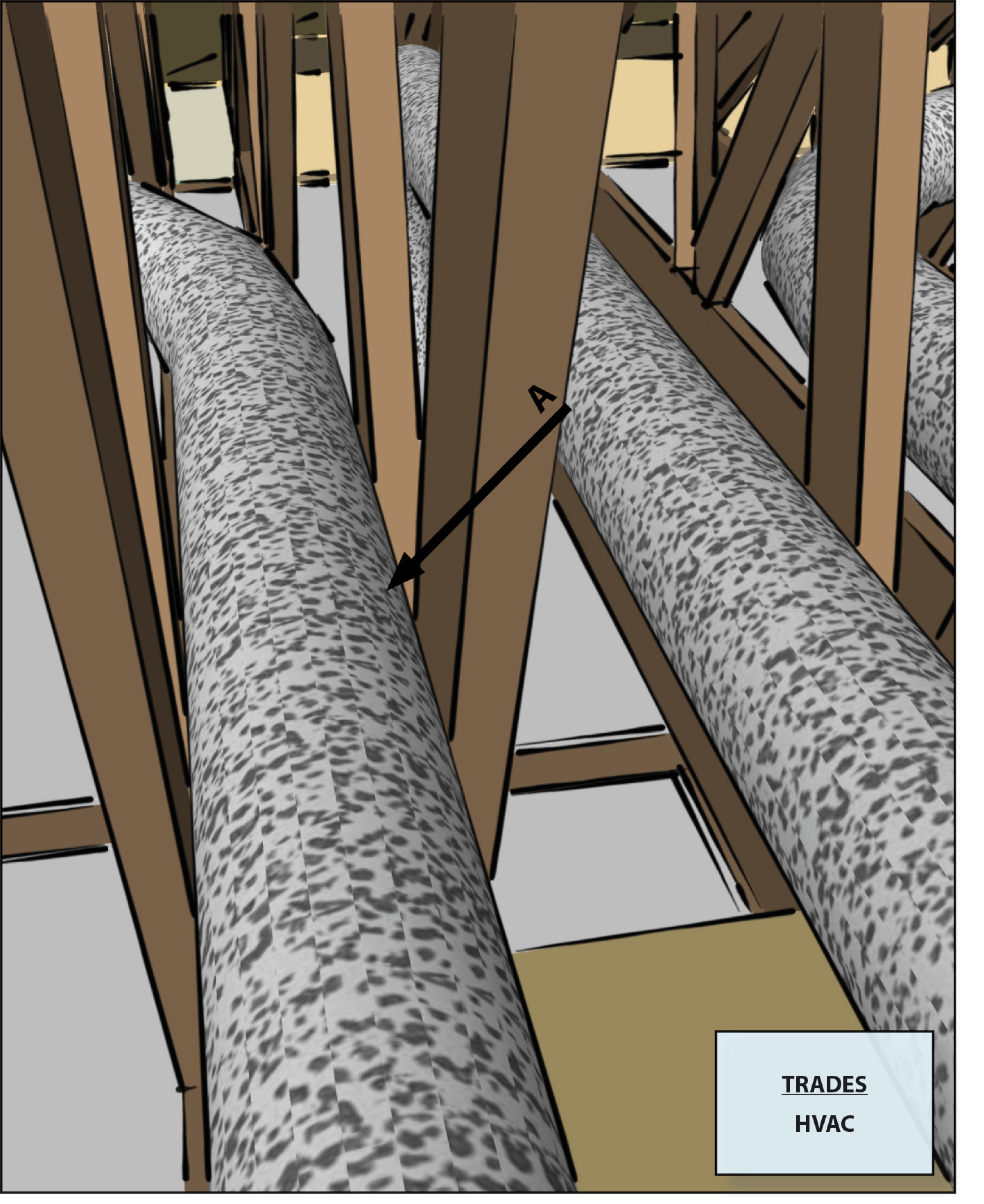
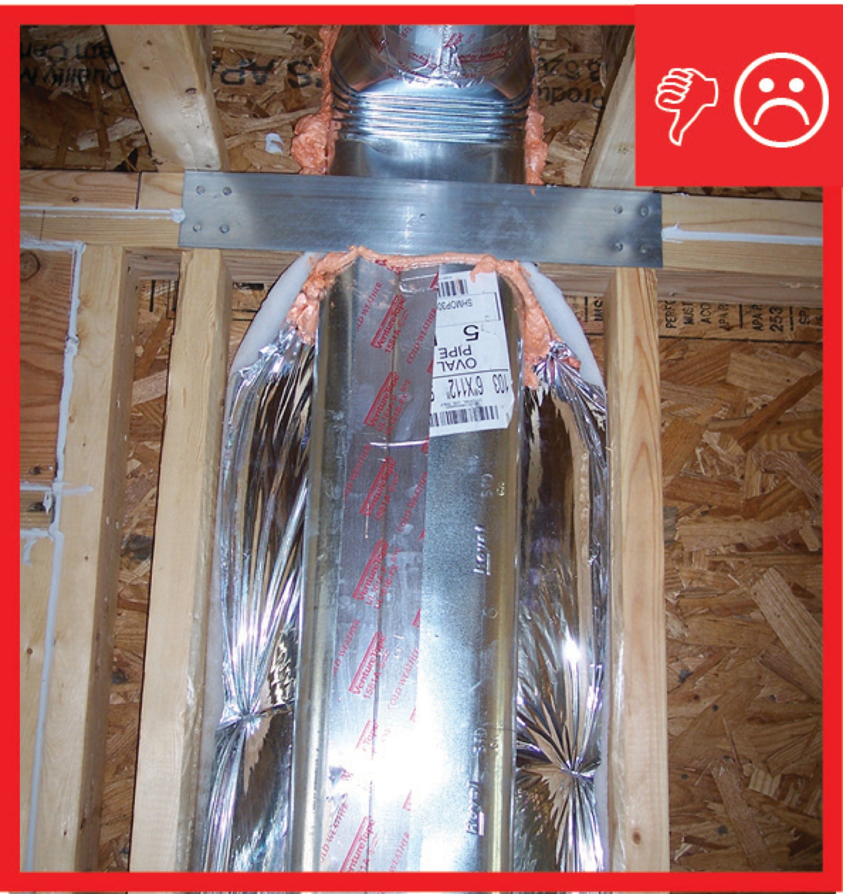
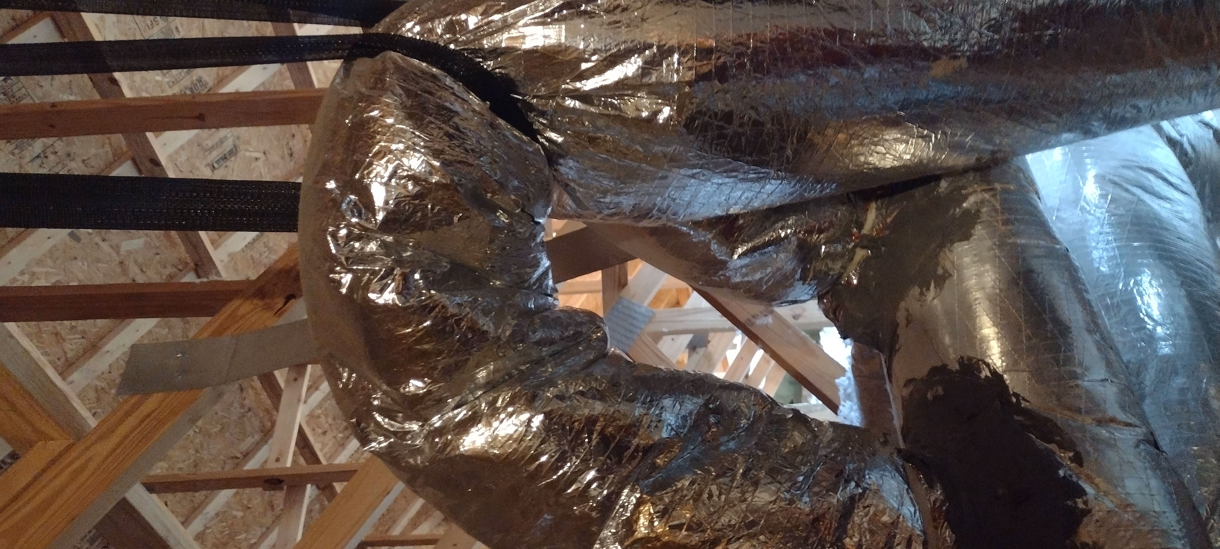
Ducts are insulated but strapping is compressing the insulation therefore reducing the R-value
Image
Image
Image
Image
Image
Image
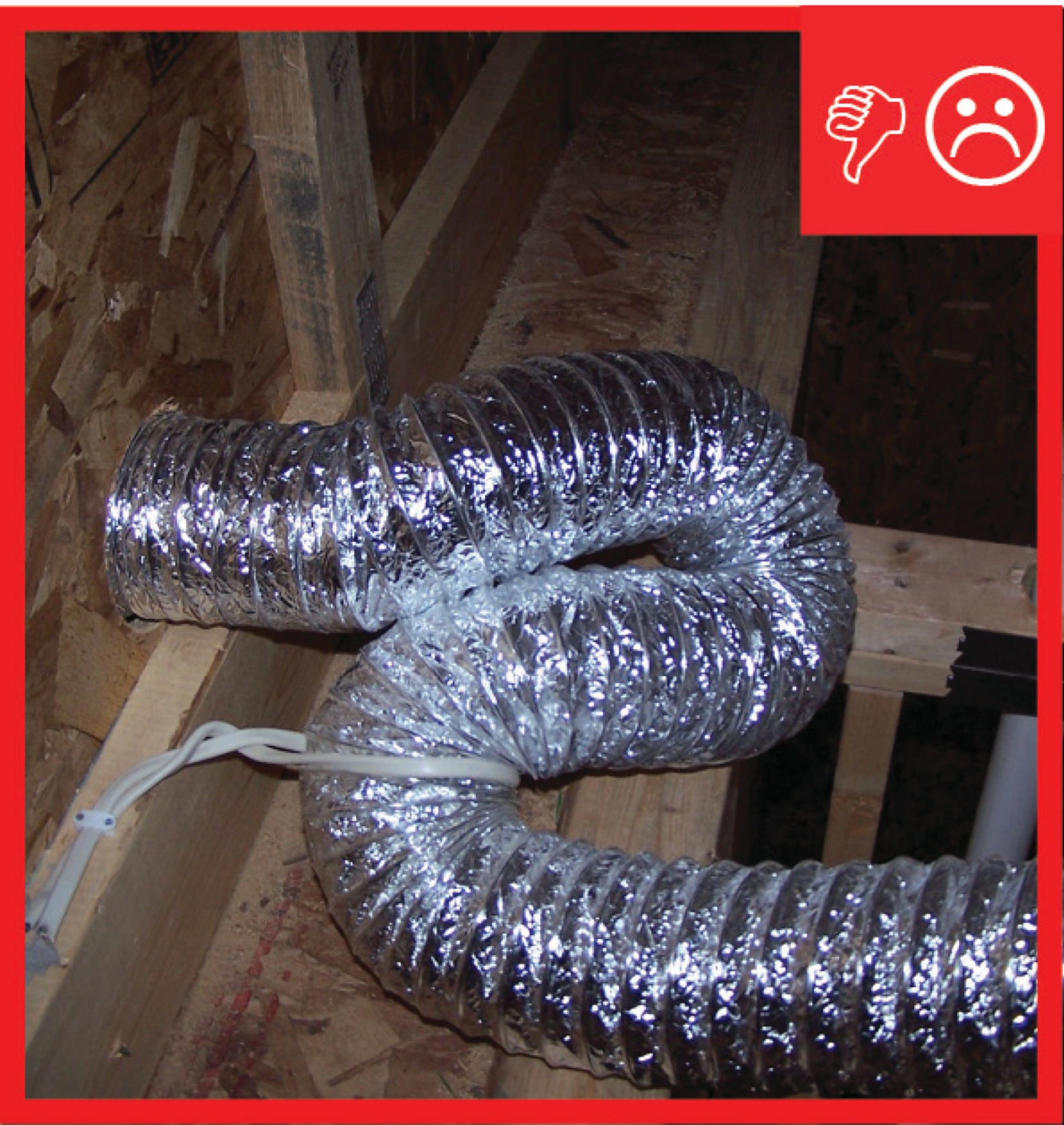
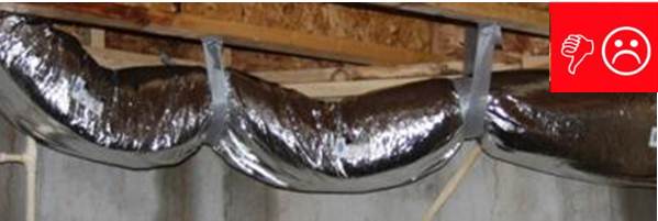
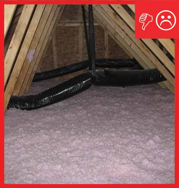
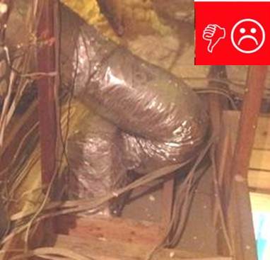
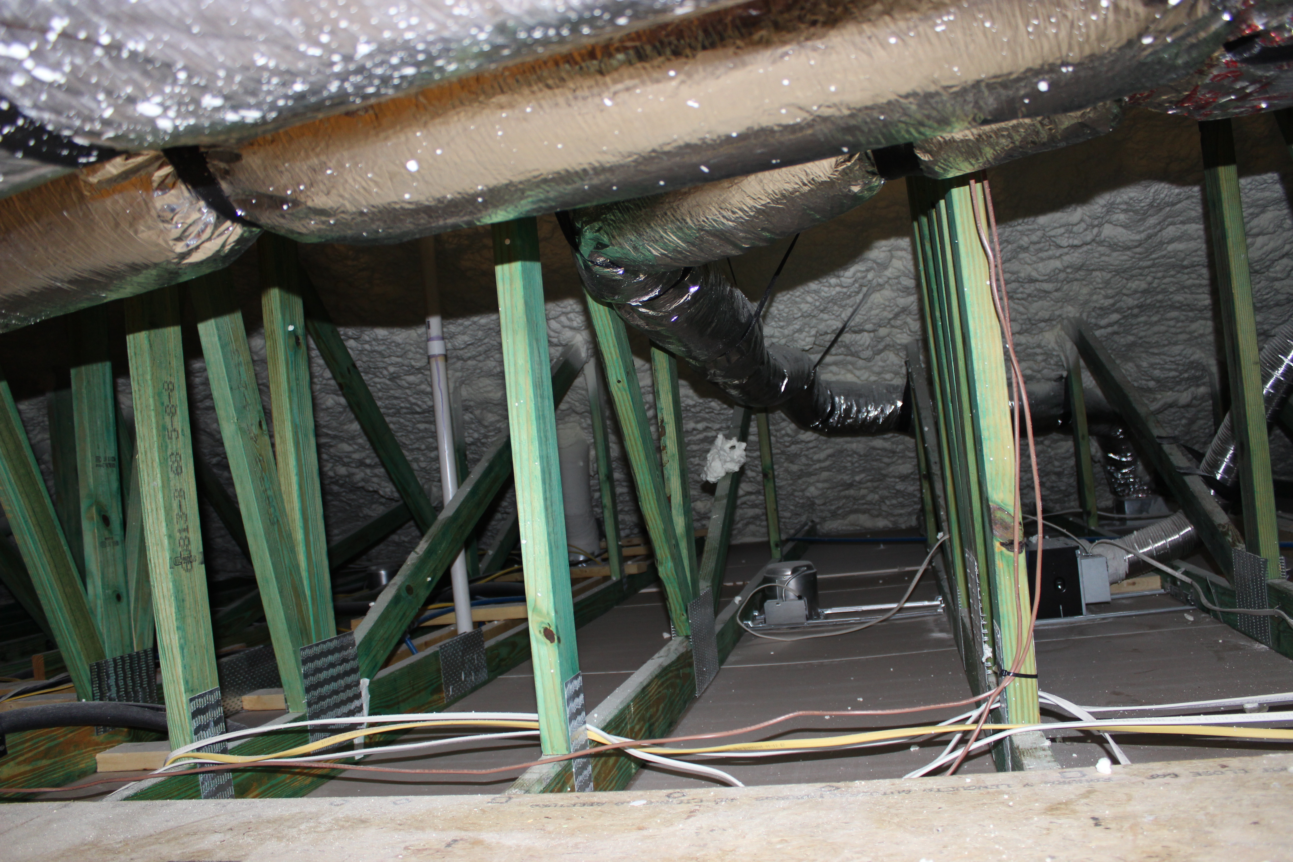
Ducts sagging because supports not installed at regular intervals
Image
Image
Image
Image
Image
Image
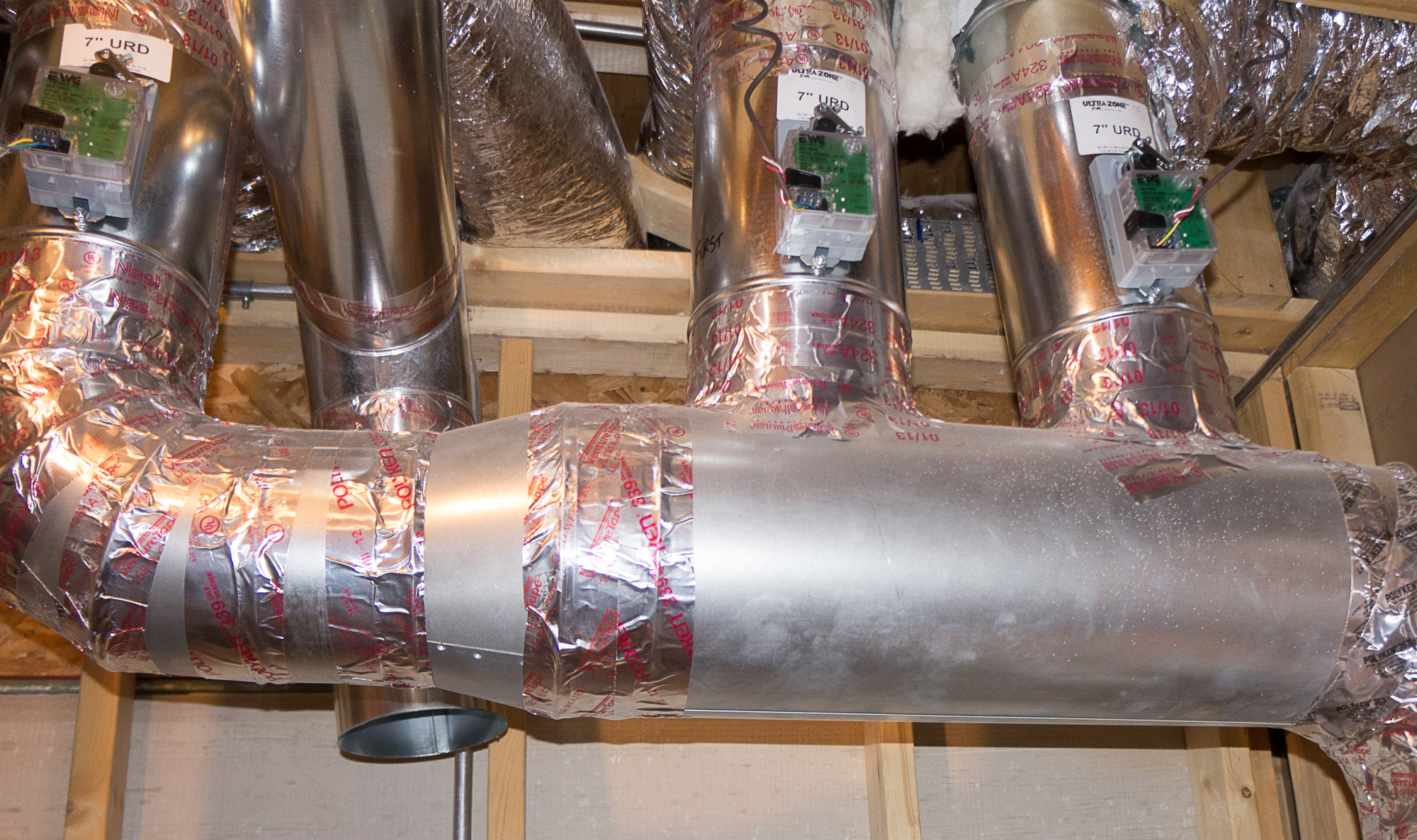
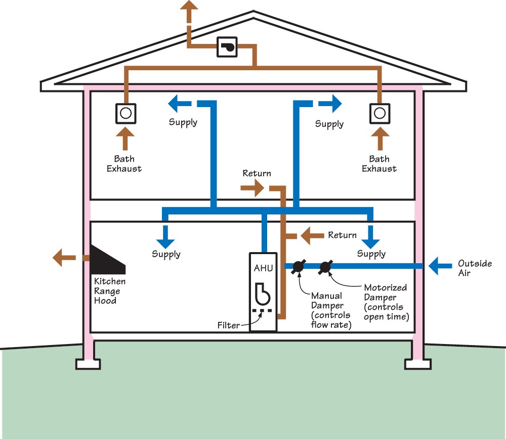
Electronically controlled dampers allow this central air system to provide zoned heating and cooling to specific parts of the home.
Image
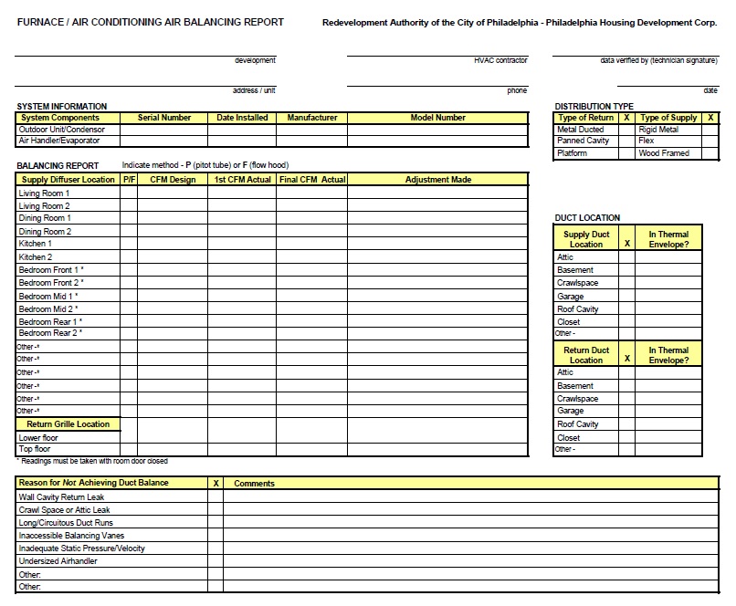
Example of an HVAC installer’s balancing report form
Image
Image
Image
Image
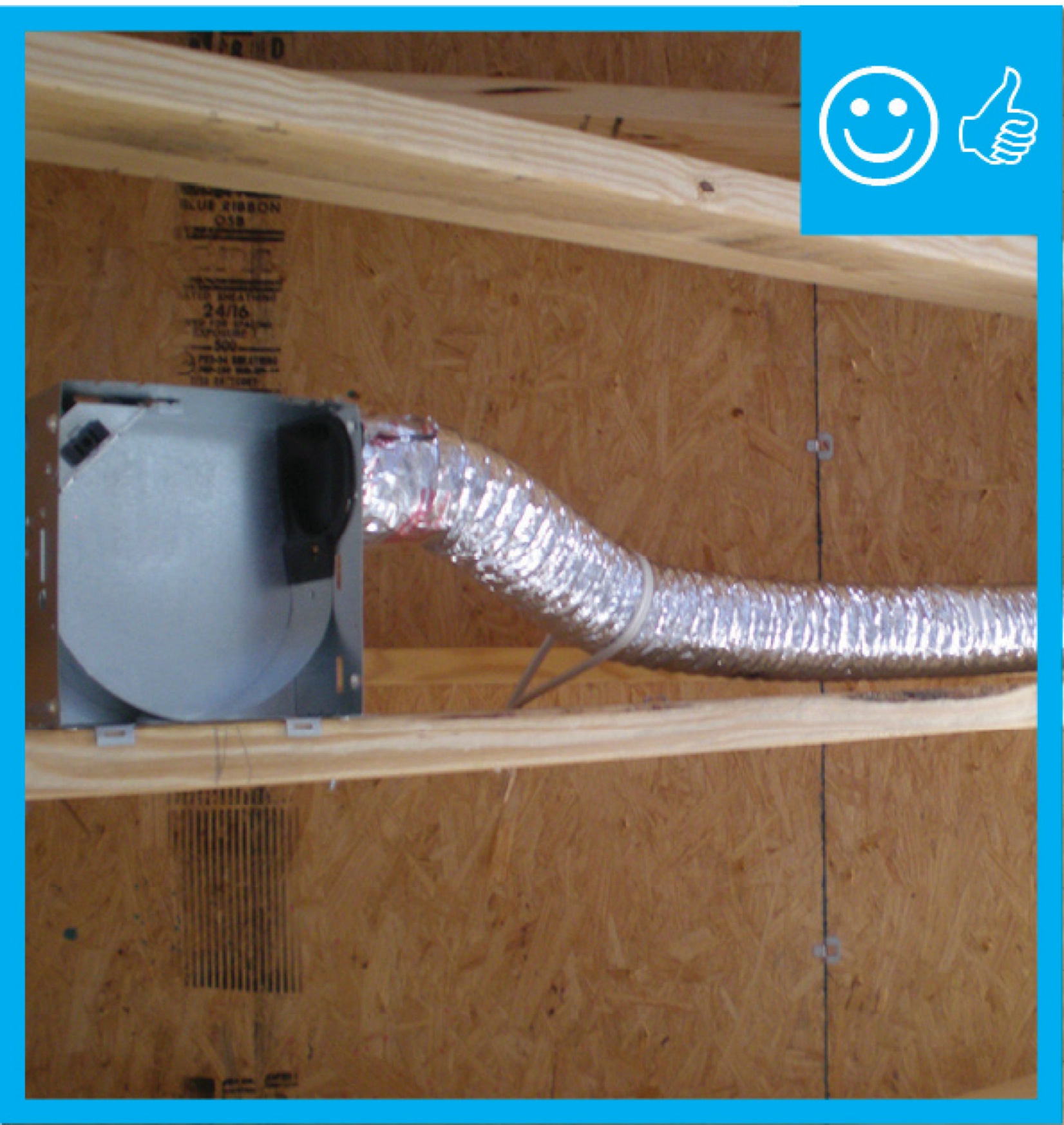
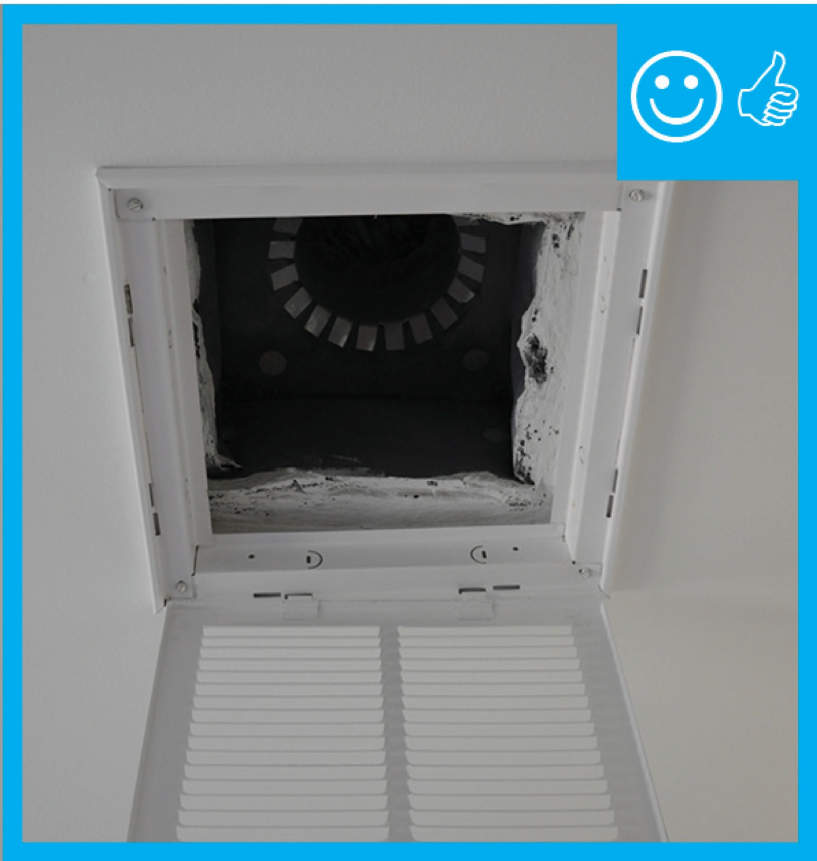
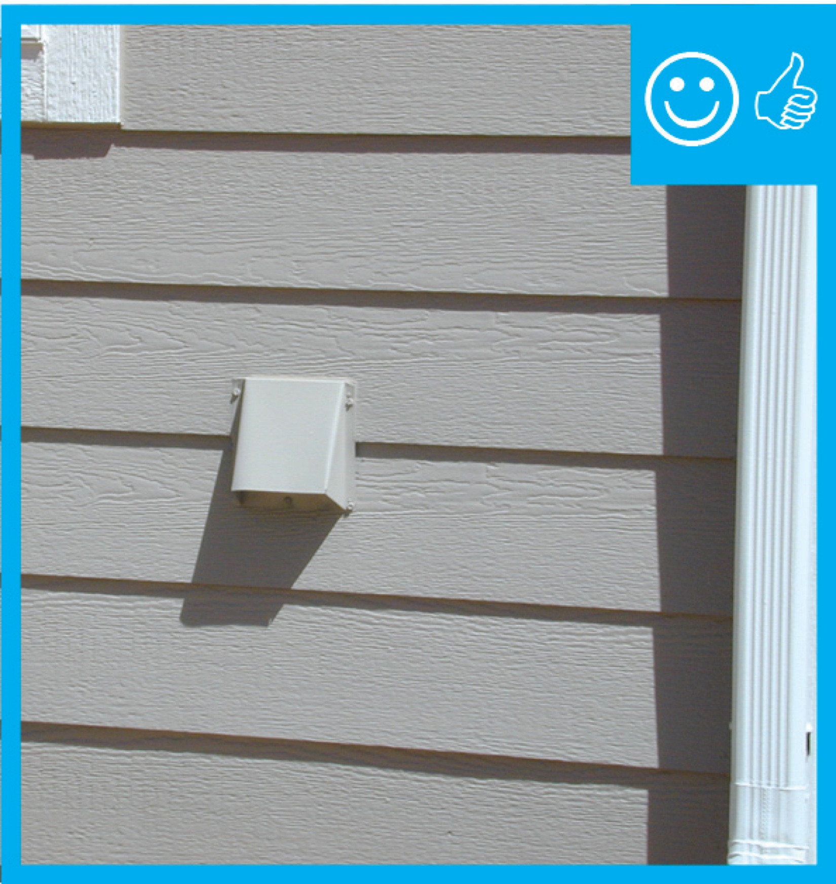
Fan housing was oriented in the correct direction to allow proper exhaust duct installation
Image
Image
Image
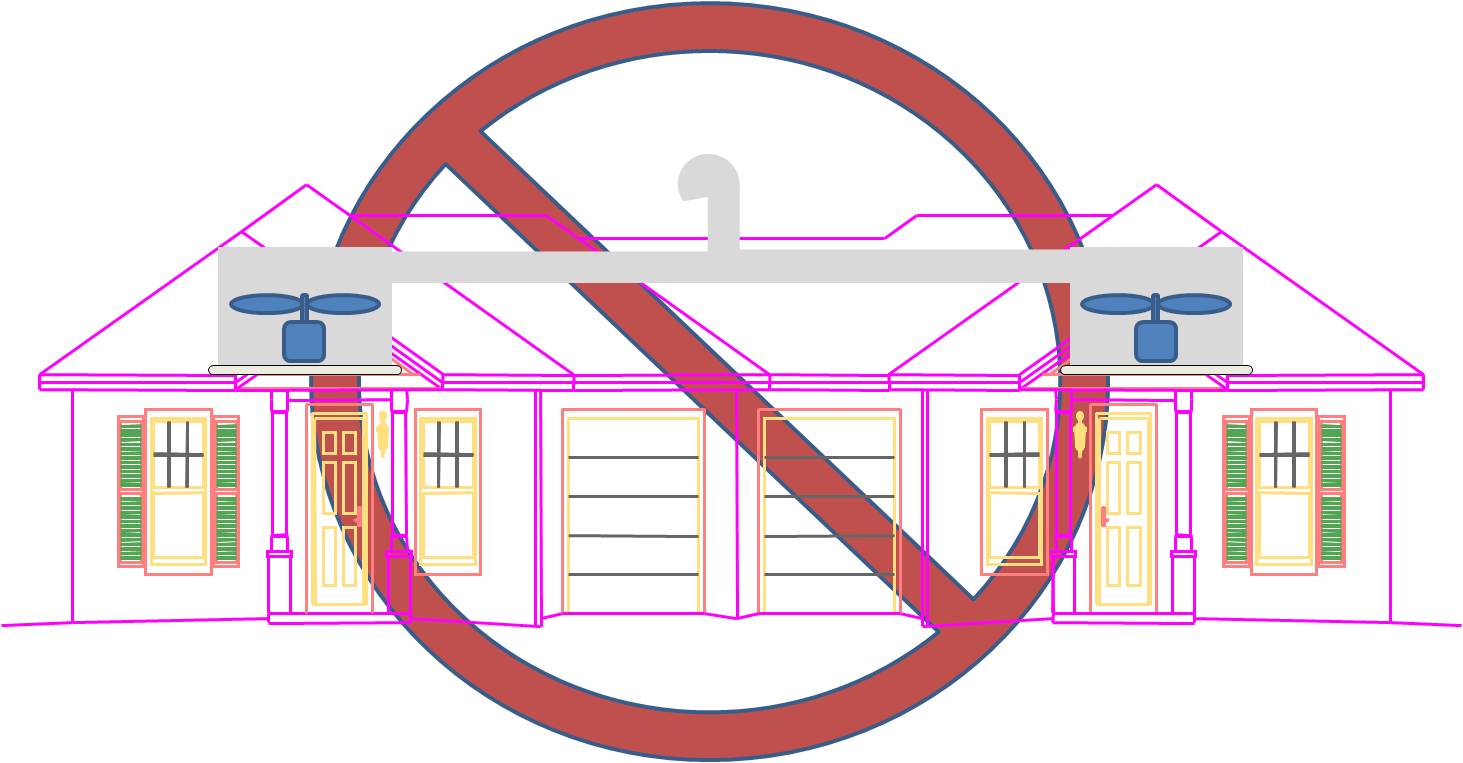
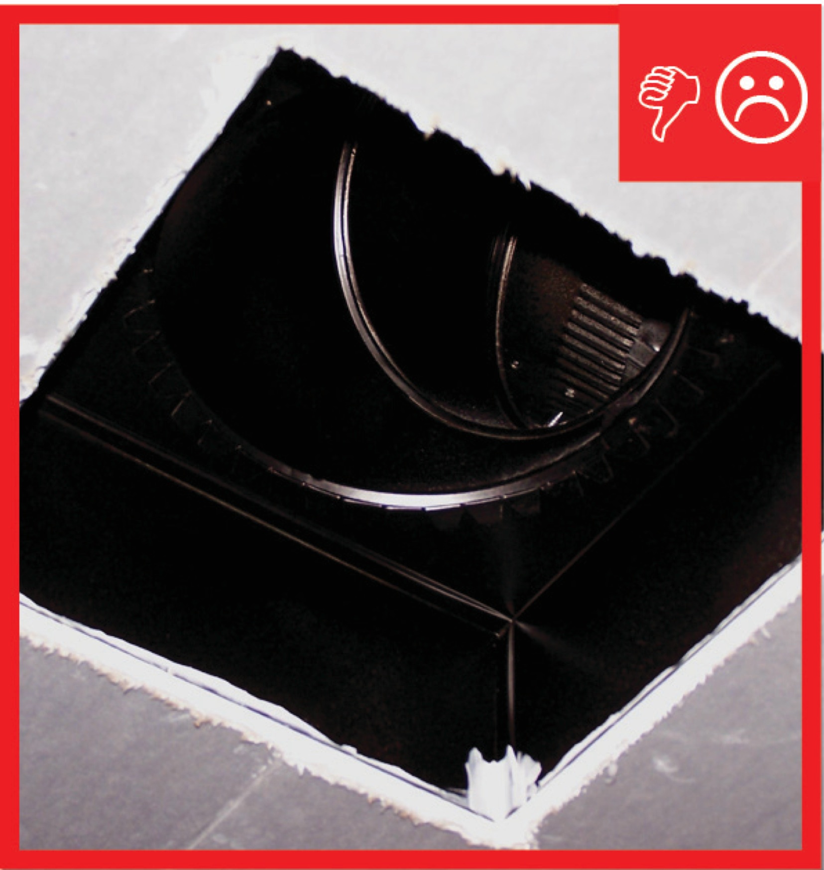
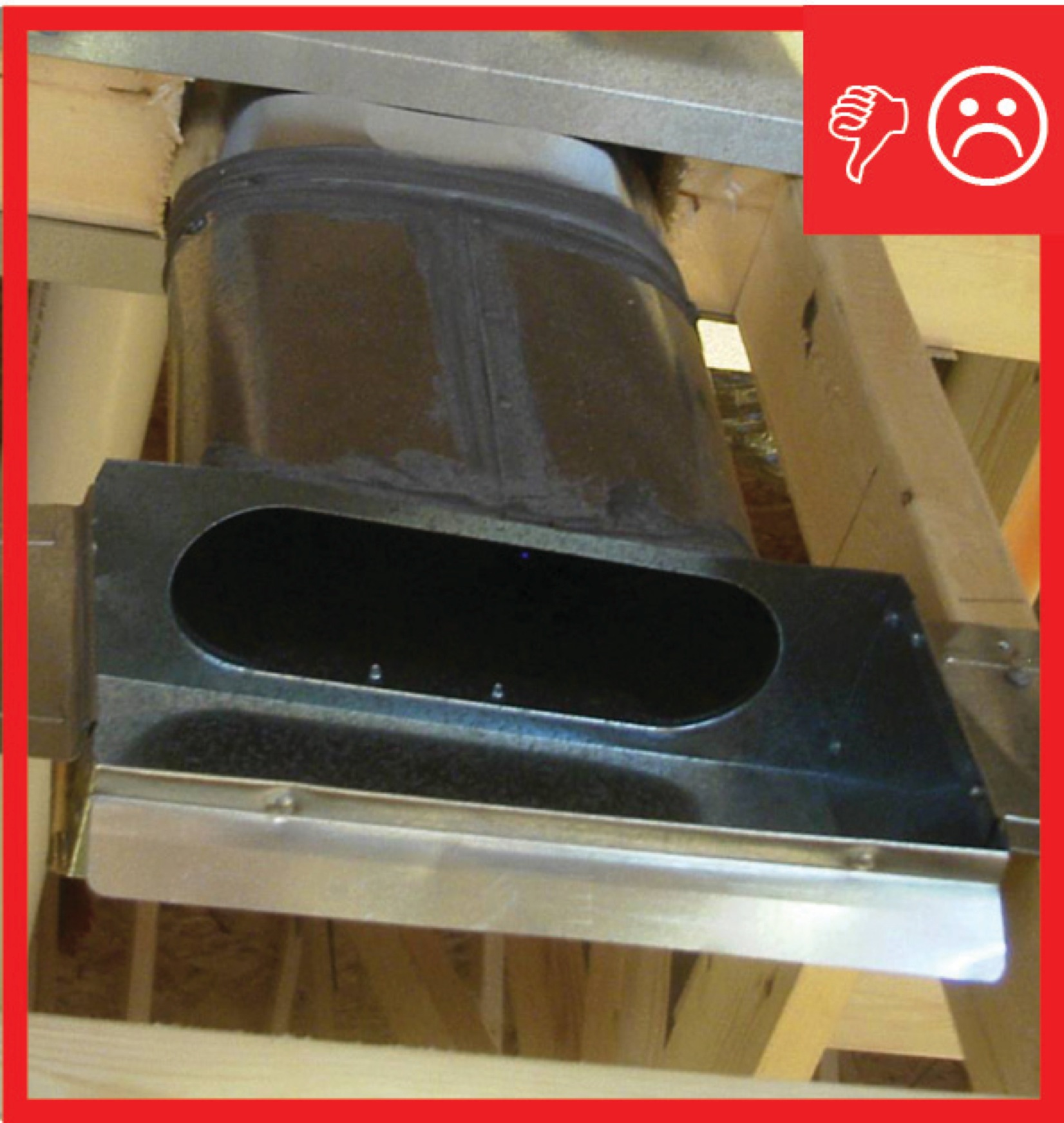
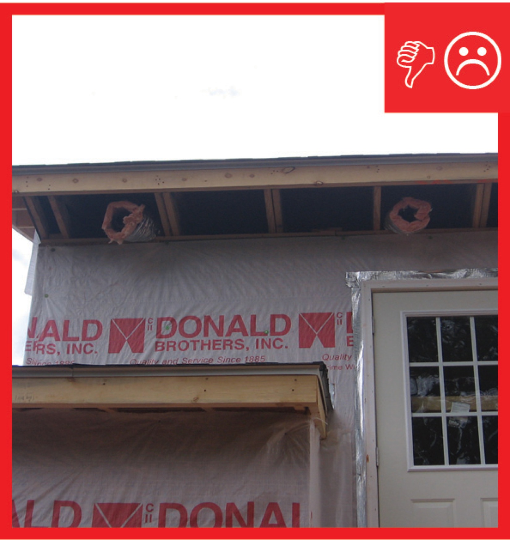
Fans from seperate dwellings exhausted together without back-draft dampers and not sealed
Image
Image
Image
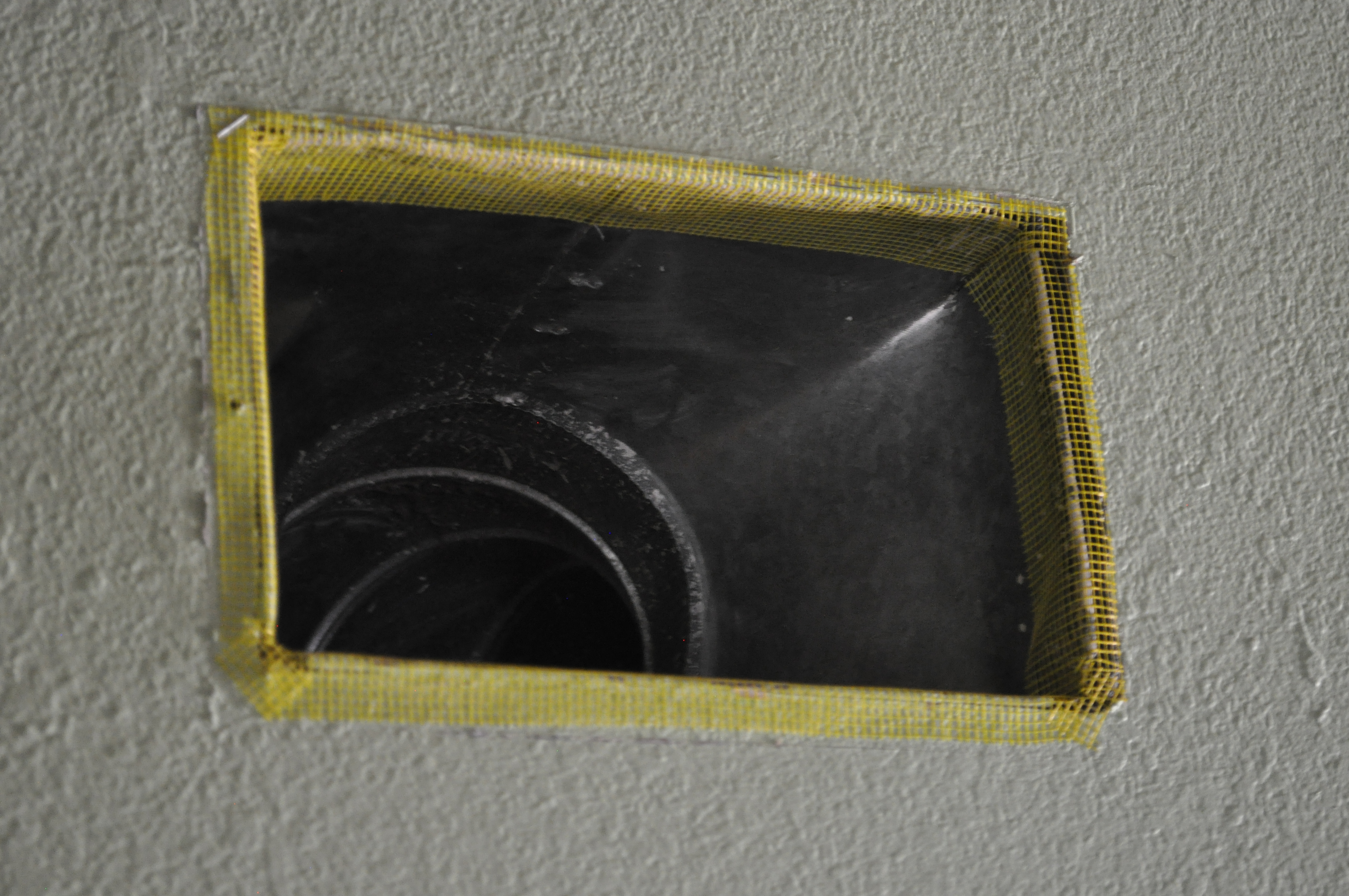
Fiberglass mesh tape is installed around a duct boot in preparation for air sealing with mastic
Image
Image
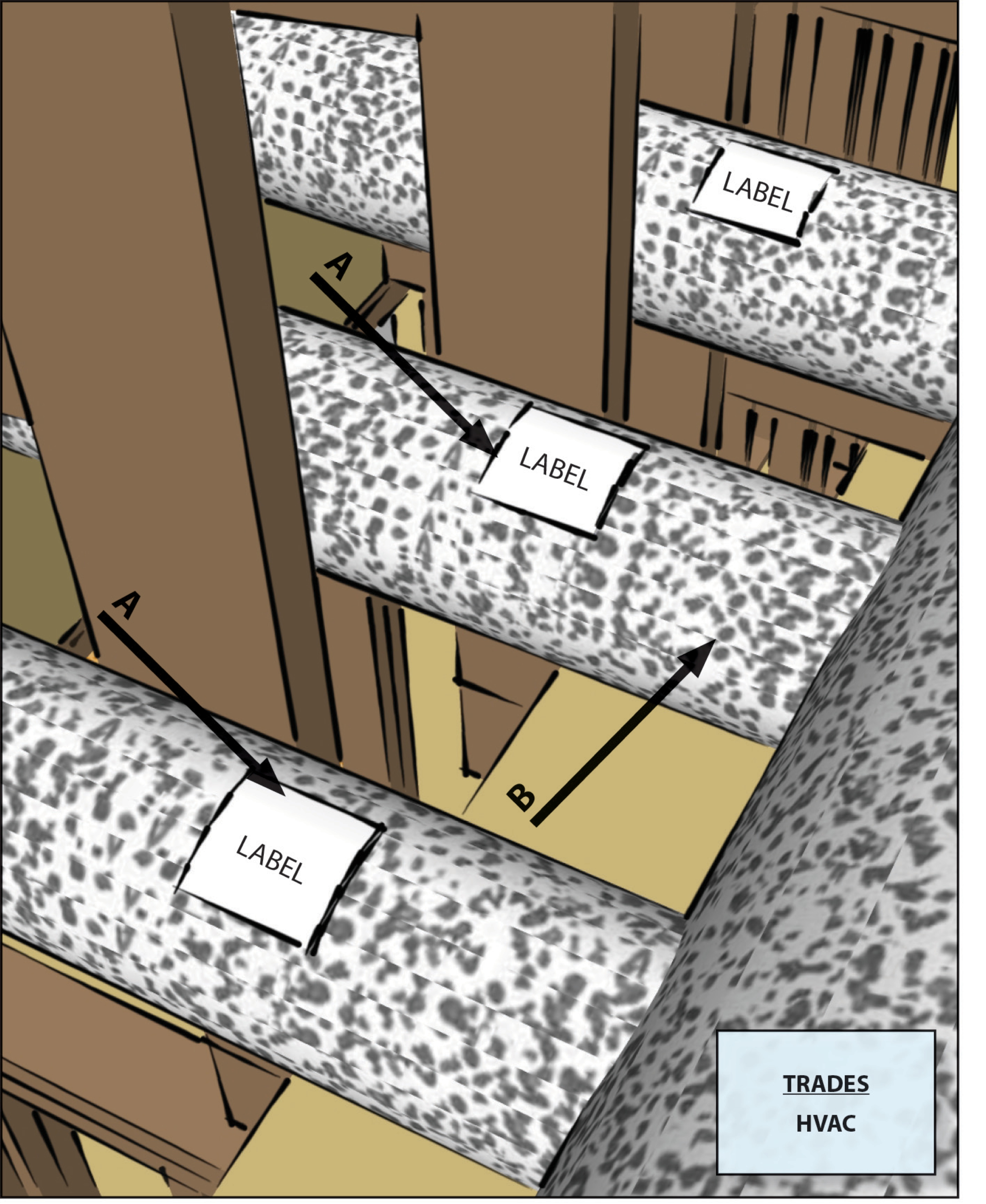
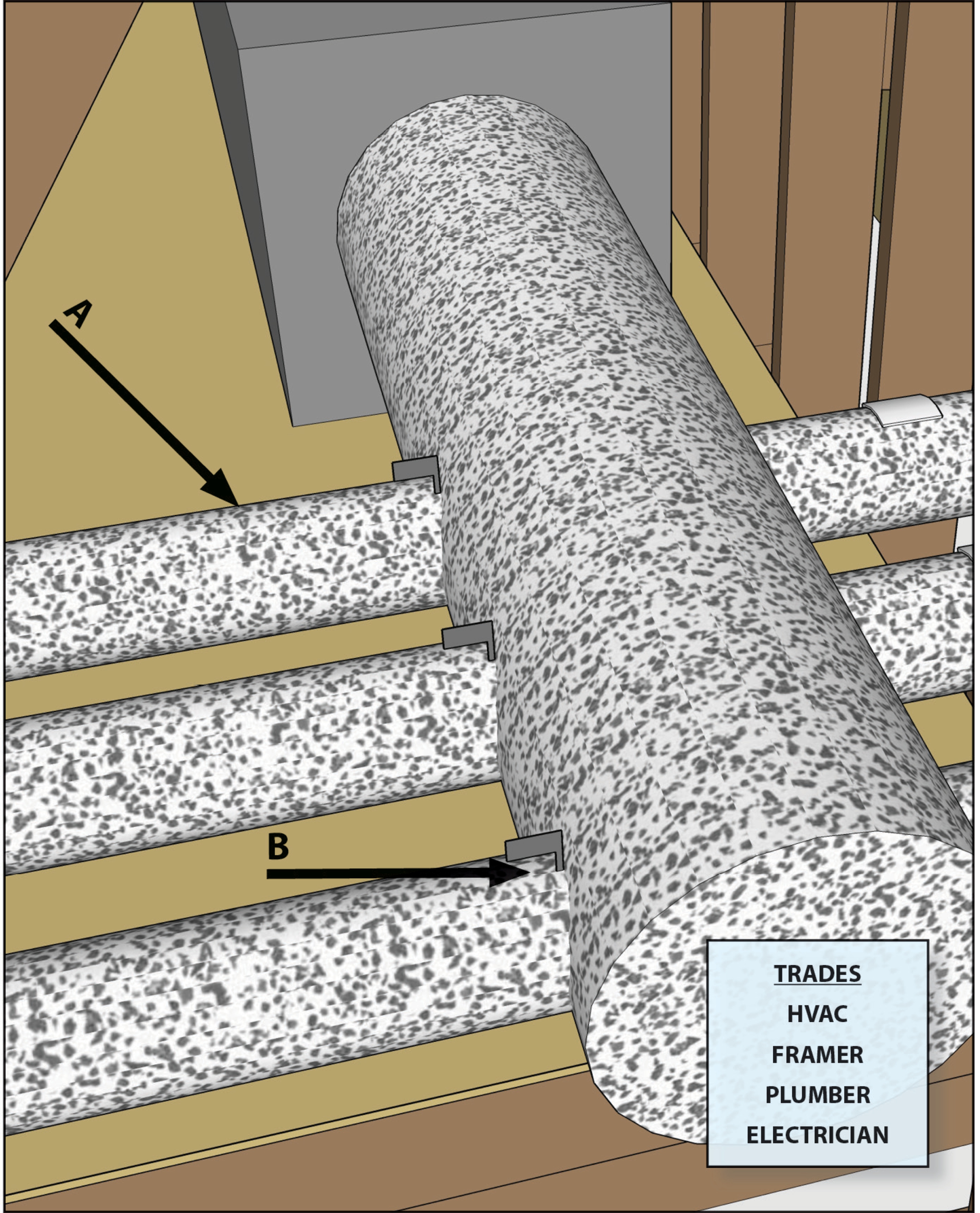
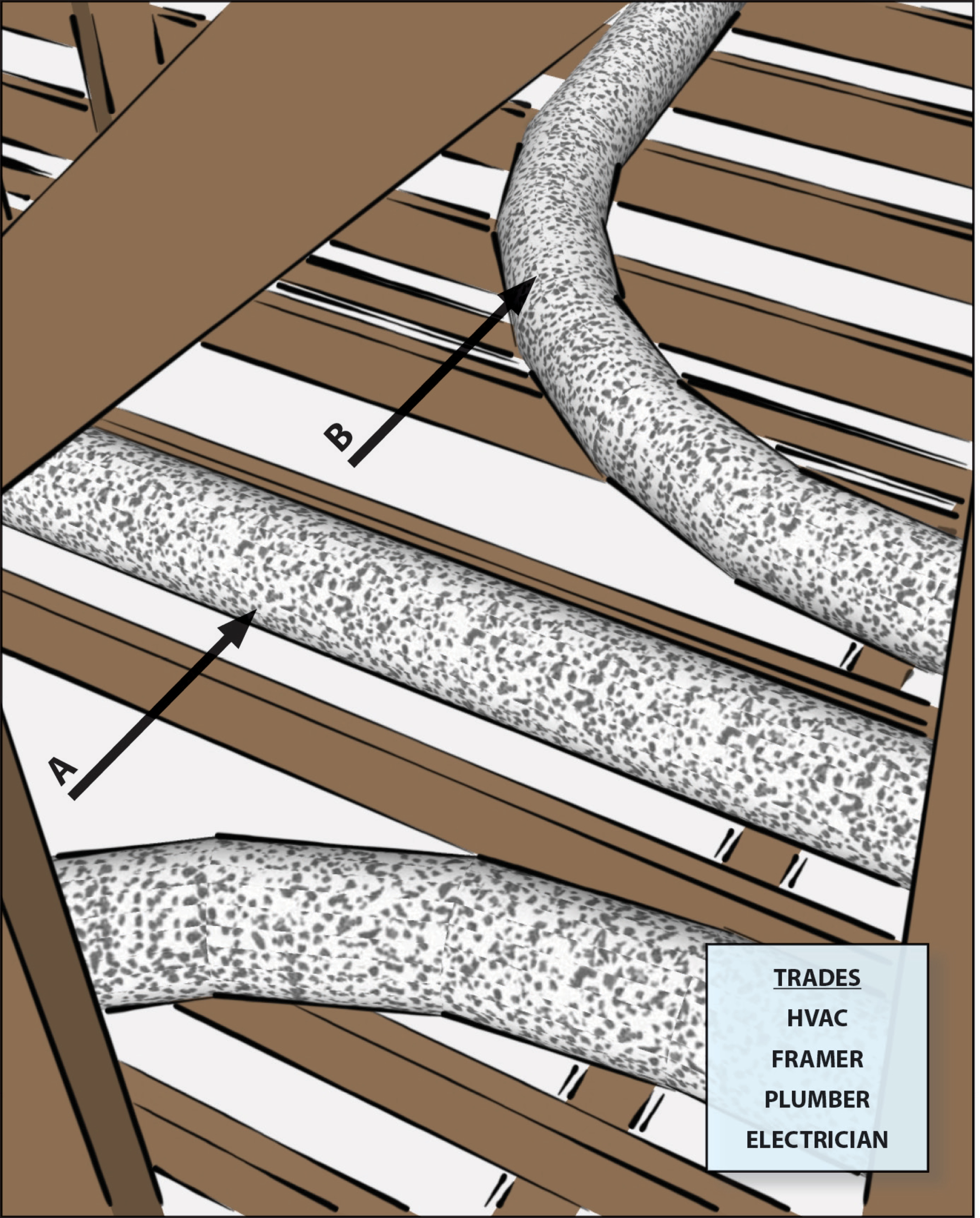
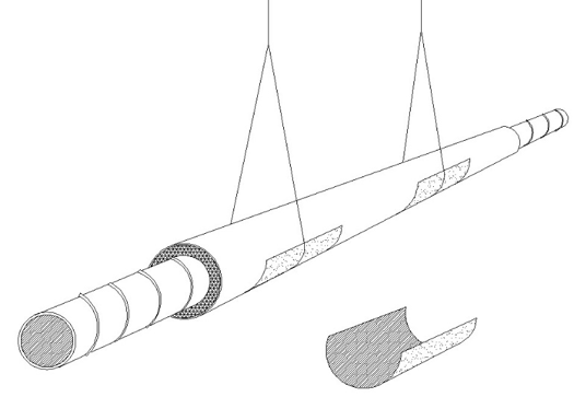
Flexible ducts in unconditioned space not installed in cavities smaller than outer duct diameter; in conditioned space not installed in cavities smaller than inner duct diameter
Image
Flexible ducts supported at intervals as recommended by mfr. but at a distance ≤ 5 ft
Image
Image
Image

Hand tools for cutting fiber board sheets include a knife, straight edge, and color-coded edge-cutting tools
Image
Image
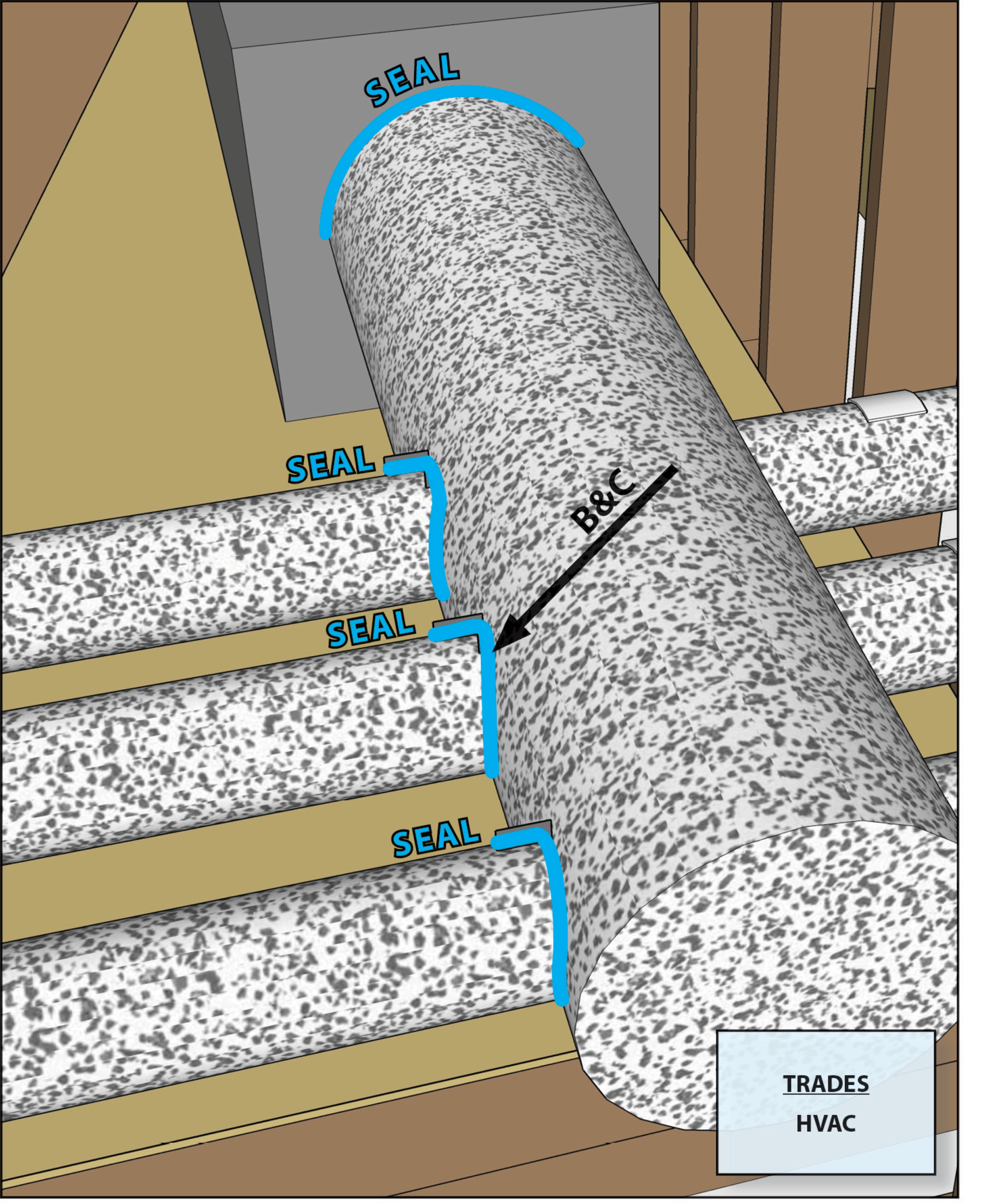
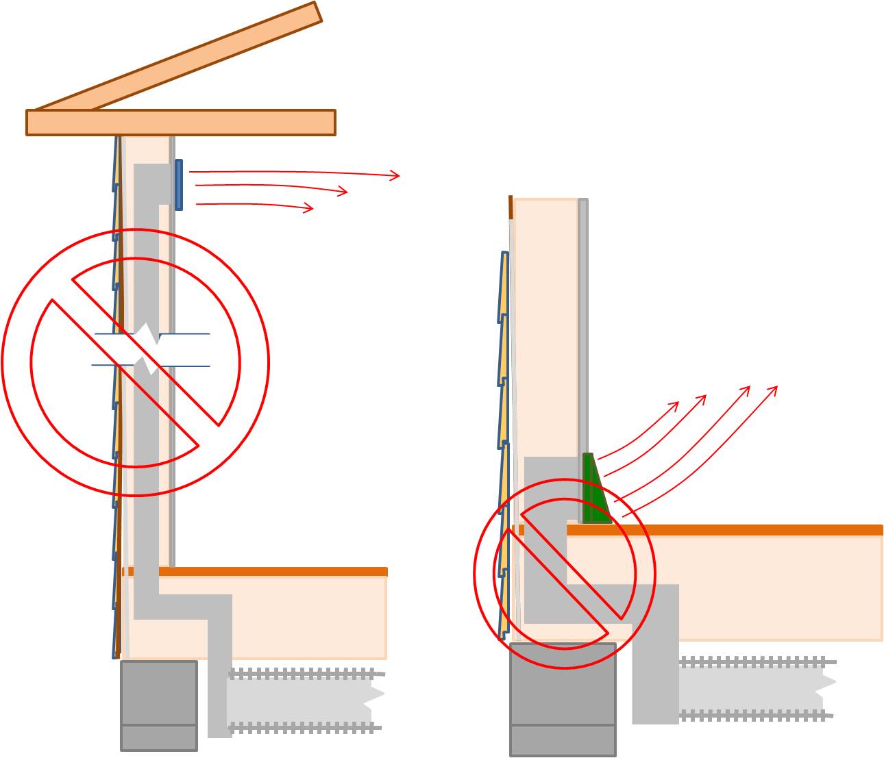
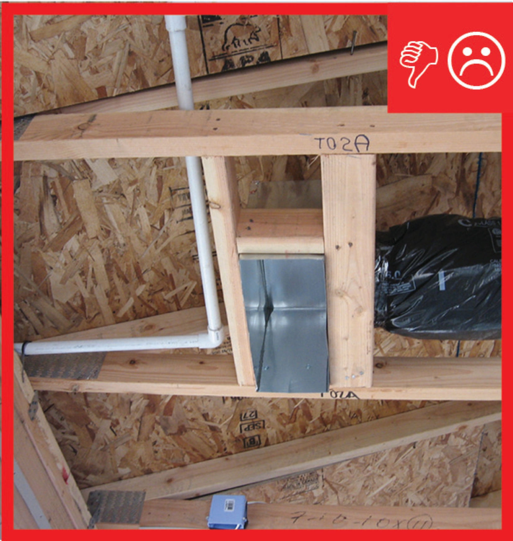
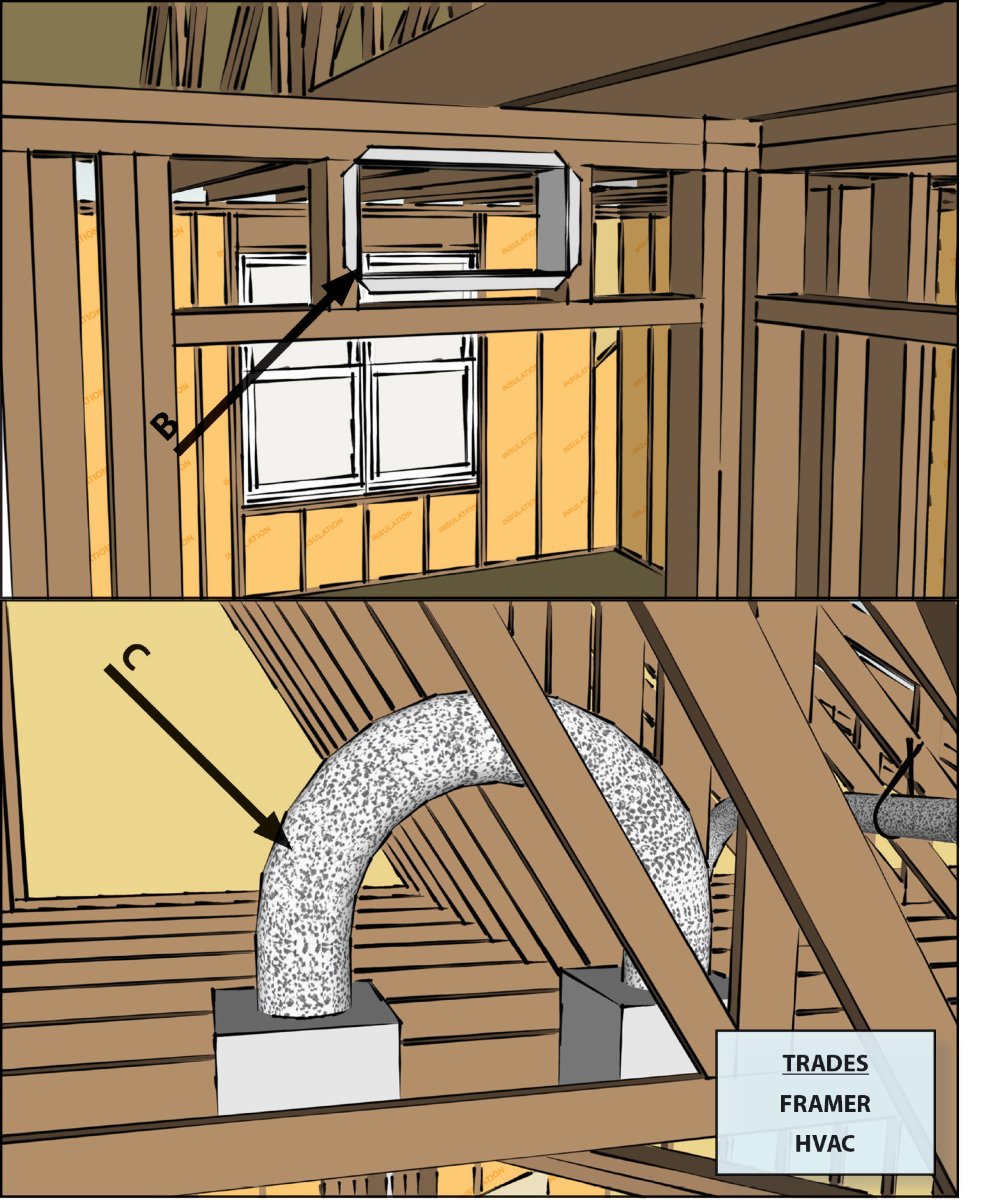
HVAC ducts, cavities used as ducts, and combustion inlets and outlets may pass perpendicularly through exterior walls but shall not be run within exterior walls unless at least R-6 continuous insulation is provided on exterior side of the cavity
Image
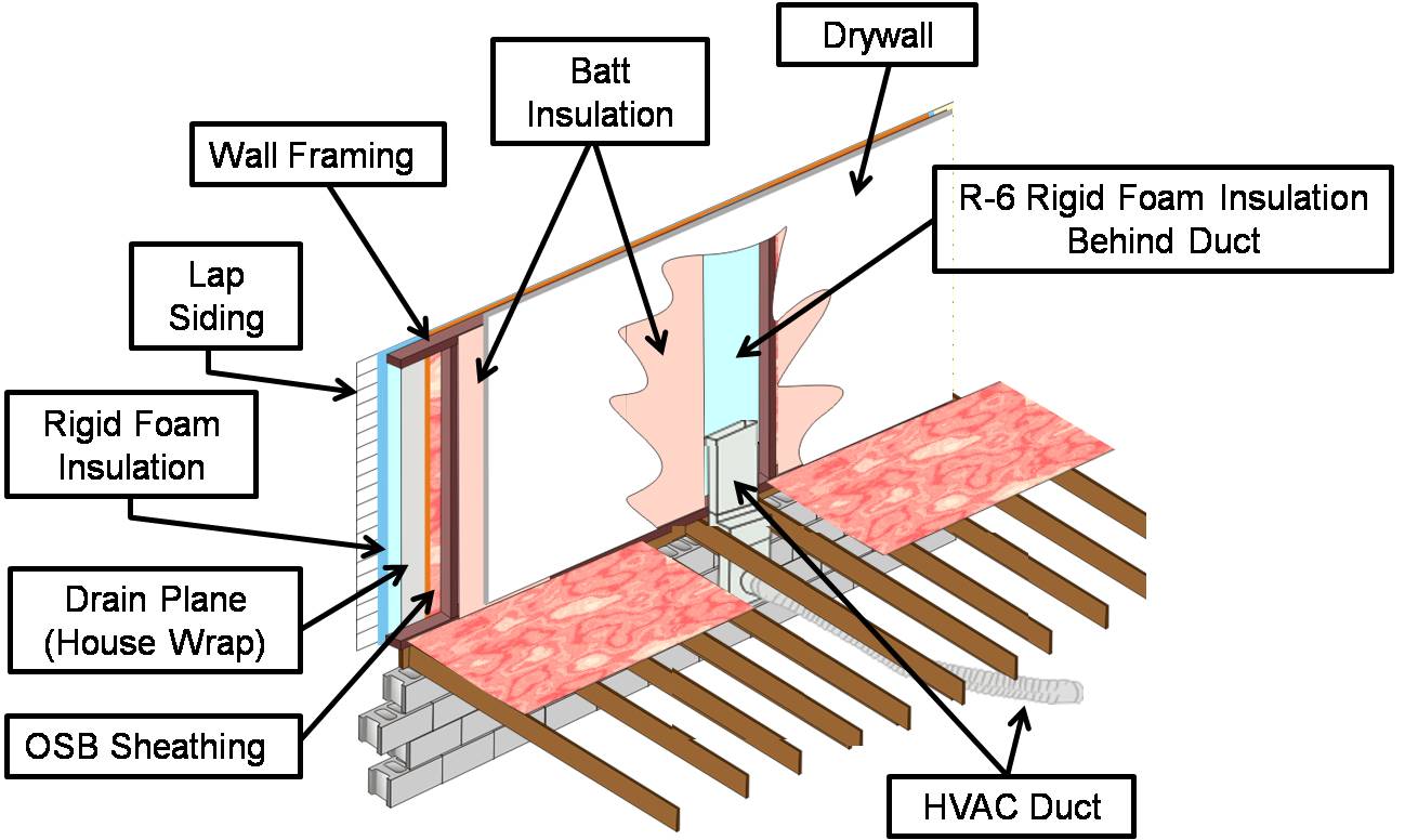
If HVAC duct must be installed in an exterior wall, separate it from the exterior with at least R-6 of continuous rigid insulation
Image
Image
Inadequate amount of insulation installed with compression, misalignment, and voids
Image
Image
Image
Install supply registers in floors or ceilings to avoid routing ducts through exterior walls
Image

Image
Image
Image
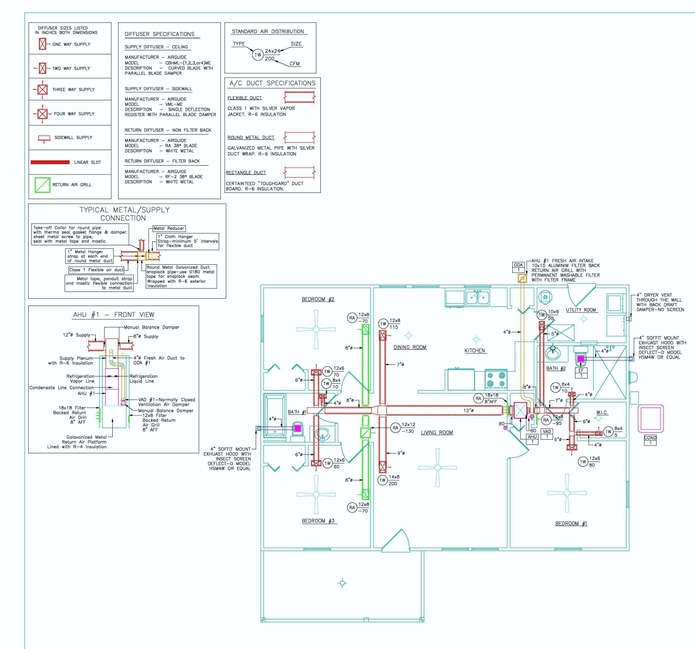
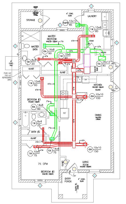
Manual D details show duct size and chase path
Image
Image
Image
Image
Image
Image
Image
Image
Image
Image
Image
Image
Image
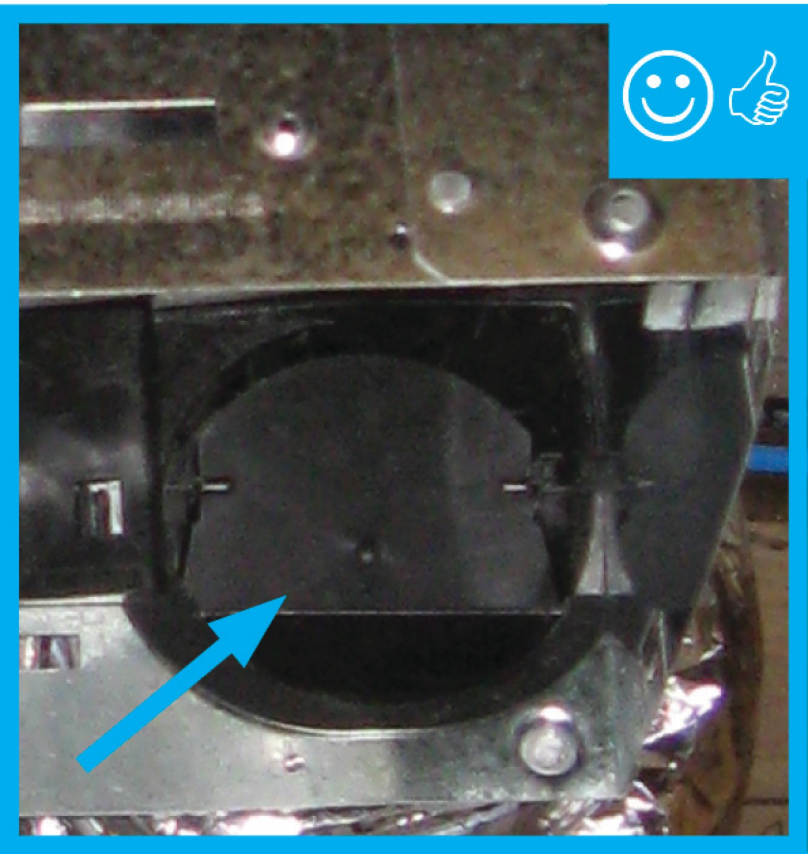
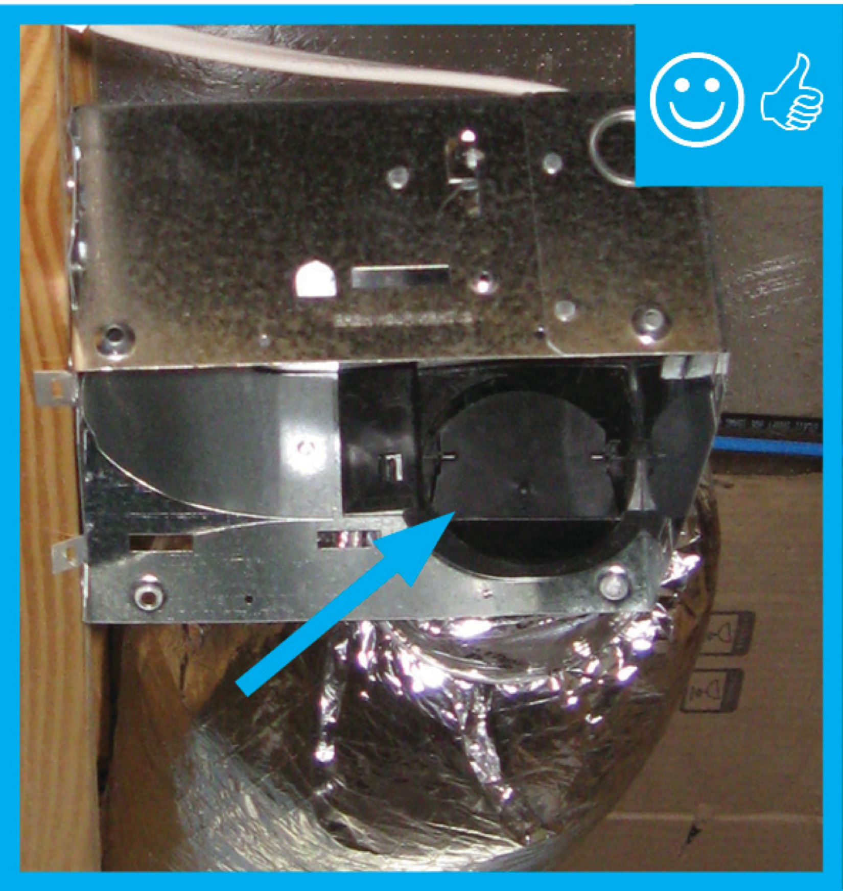
Packing tape has been removed and damper will be able to function properly once fan is installed
Image

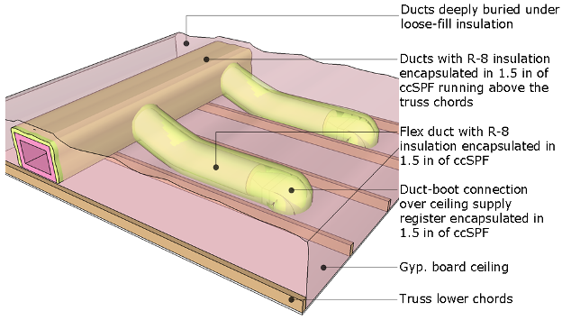
Prescriptive Path: Supply ducts in unconditioned attic have insulation ≥ R-8. Performance Path: Supply ducts in unconditioned attic have insulation ≥ R-6
Image
Image
Pull the insulation and outer liner of the flex duct over the collar to come in full contact with the liner and insulation of the trunk line or fitting and tape in place
Image
Rater-measured duct leakage to outdoors ≤ 4 CFM25 per 100 sq. ft. of conditioned floor area
Image
Image
Image
Image
Image

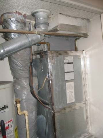
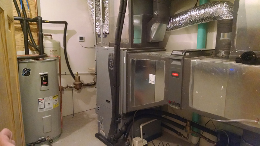
Right - All seams in the HVAC equipment and ductwork are sealed with mastic; because the HVAC equipment is in the garage, it is an air-sealed closet.
Image
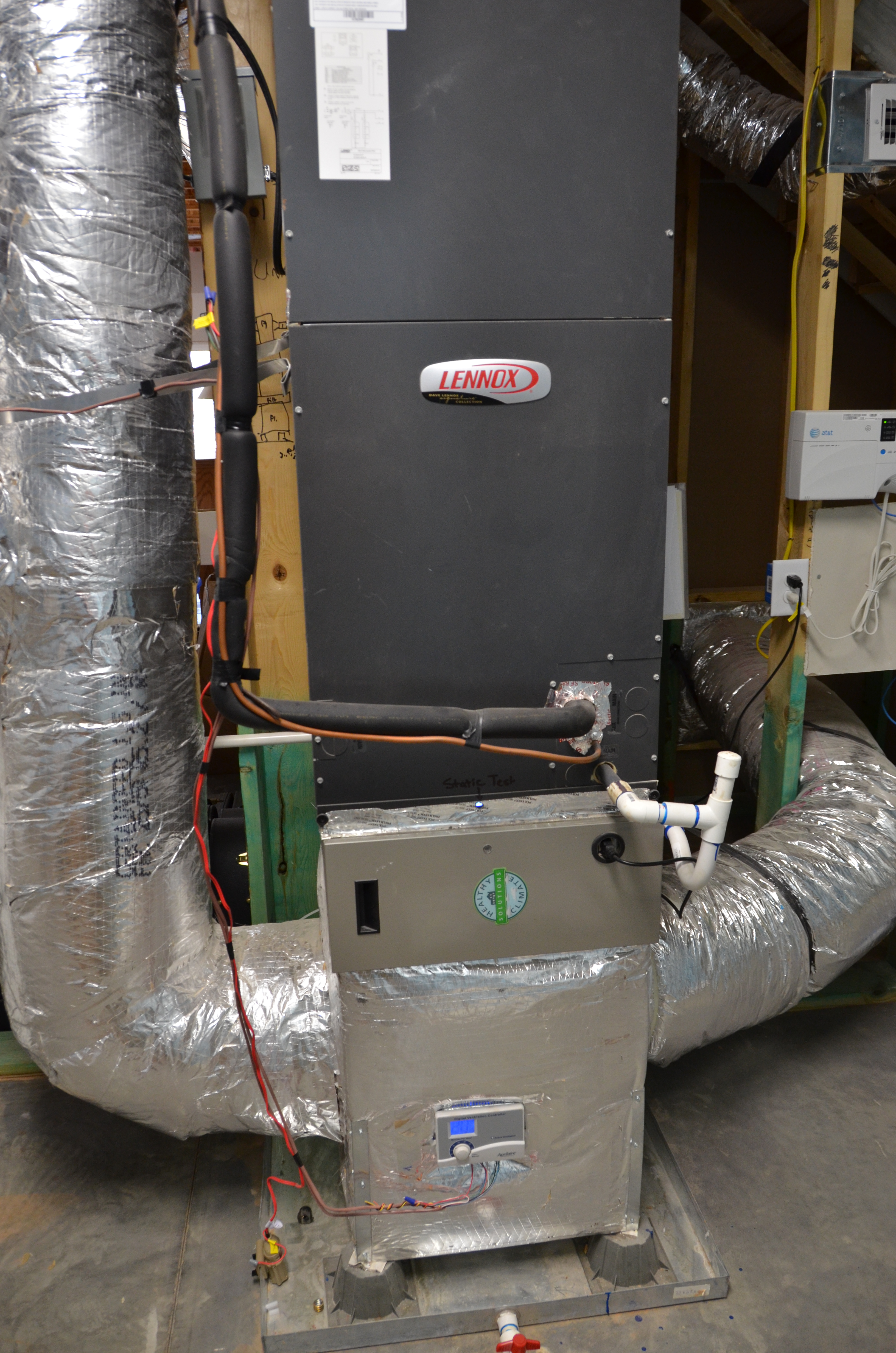
Right - An ultra-efficient (COP 5.7) ground source heat pump provides hot water to an air coil in the central air handler which uses a variable-speed electrically commutated fan motor to distribute conditioned air to the home’s ducts.
Image
Image

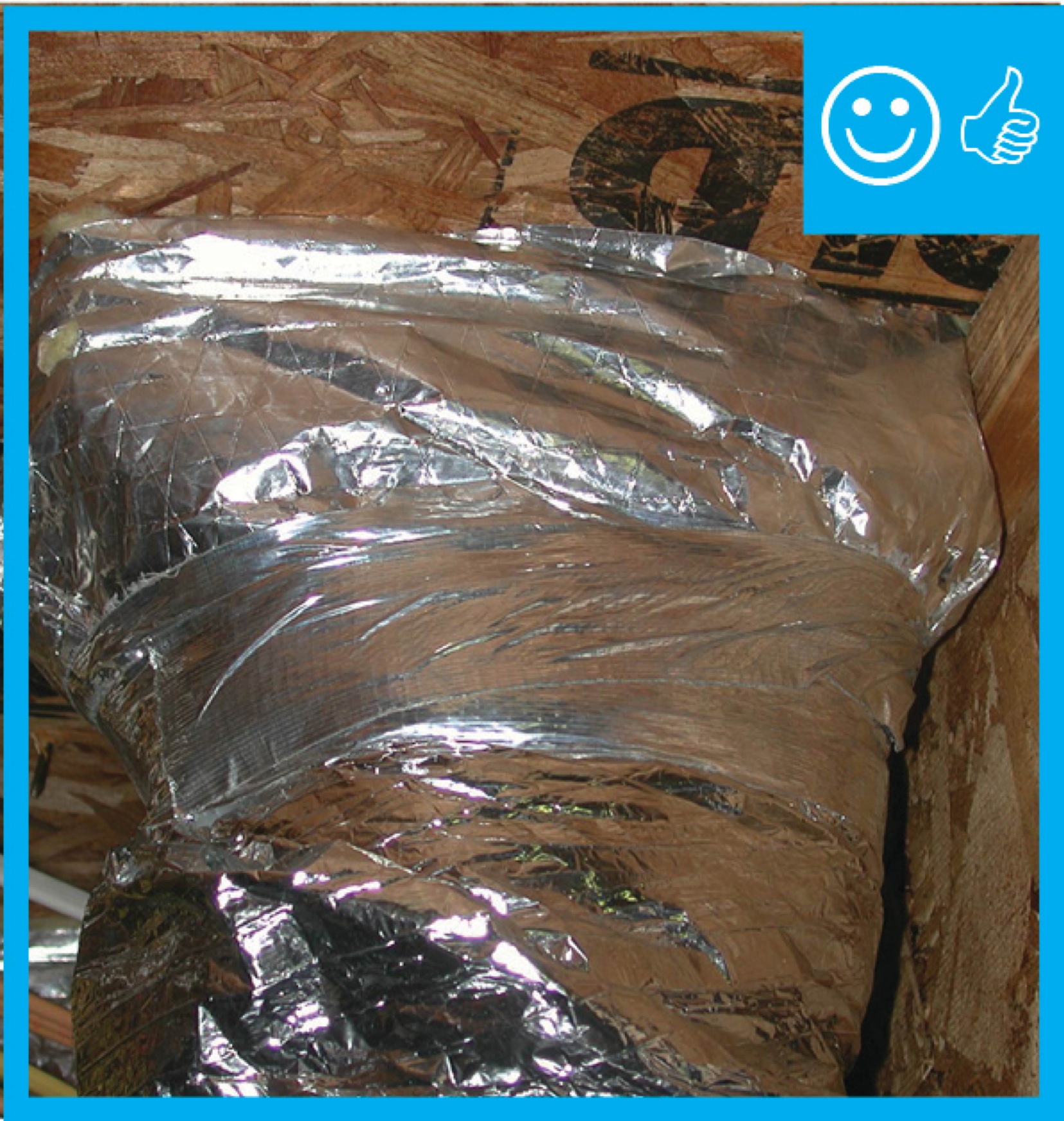
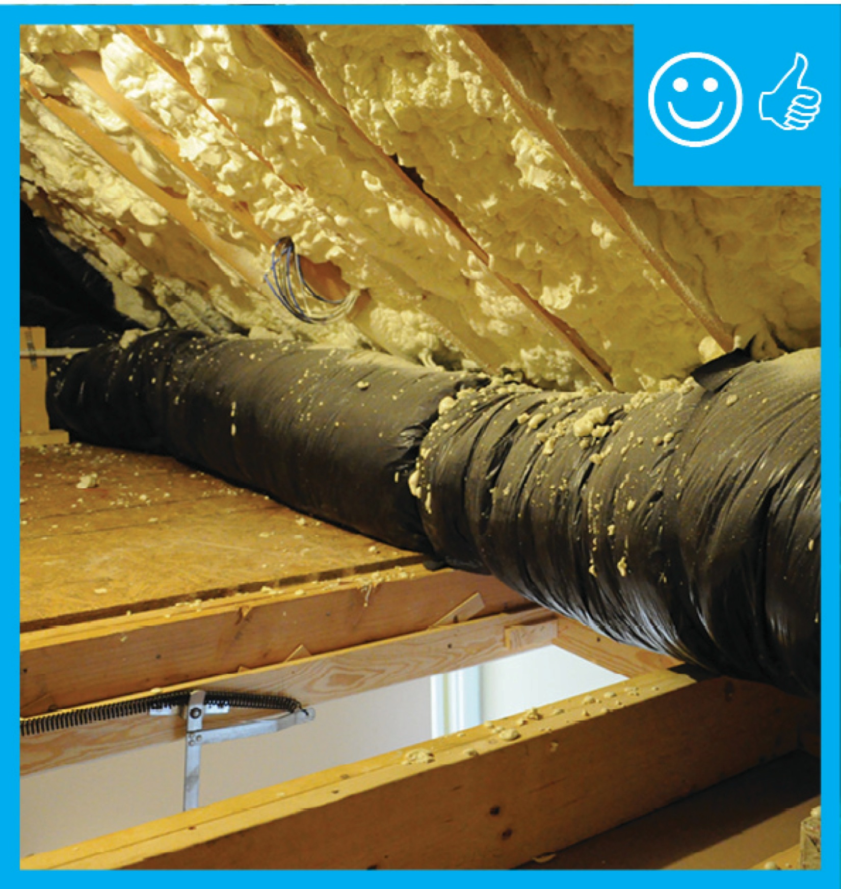
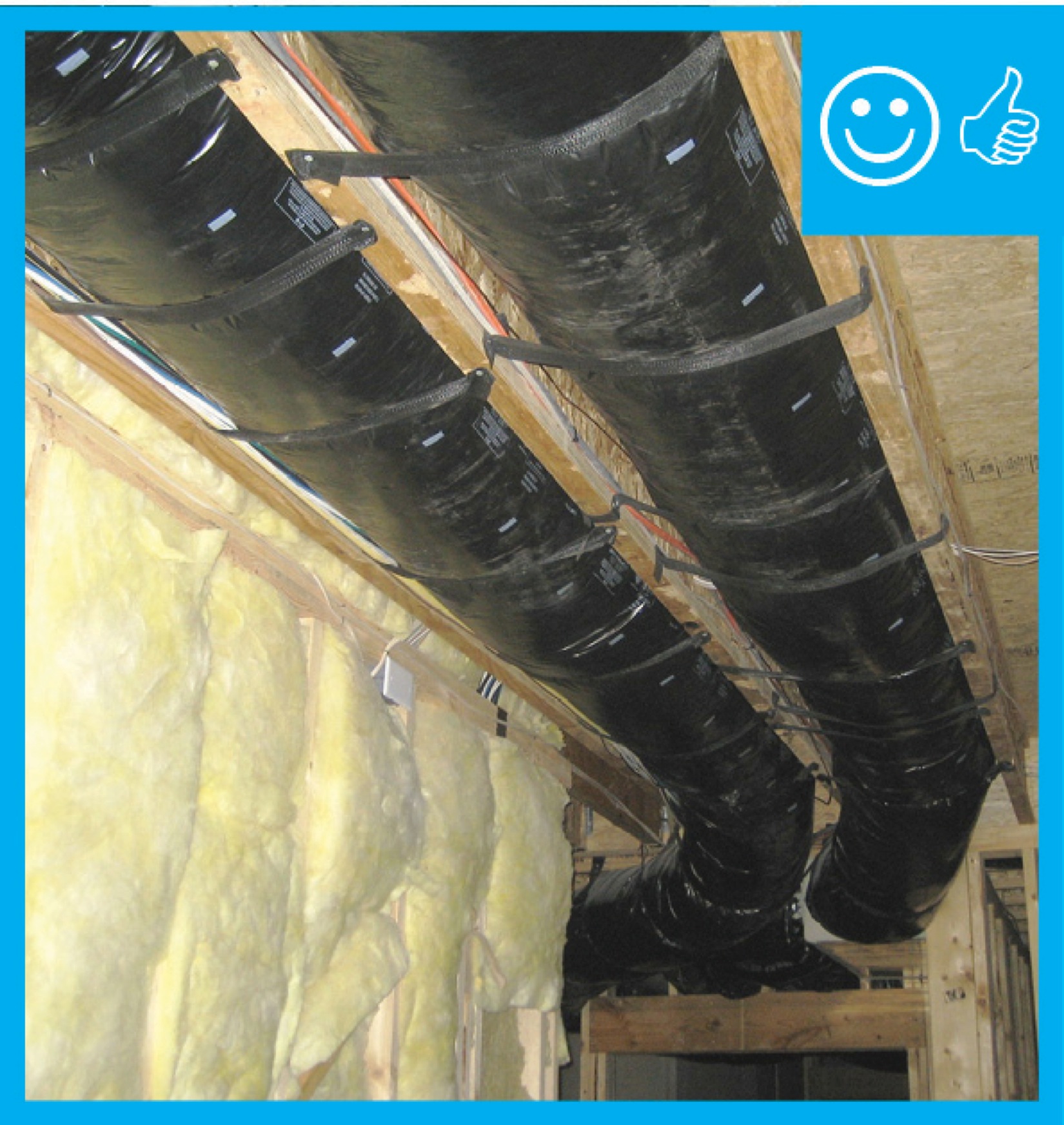
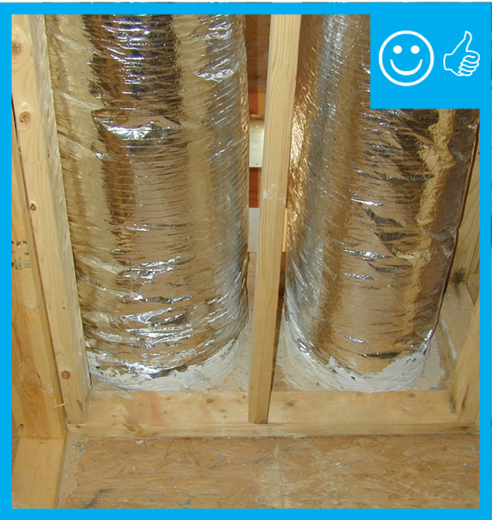
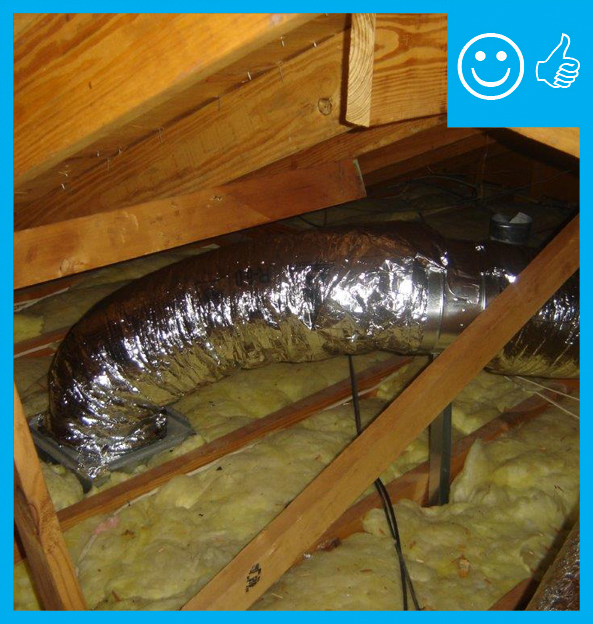
Right - Flex duct installed with adequate support and pulled taut to provide adequate air flow
Image
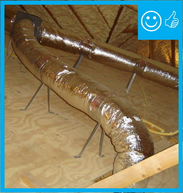
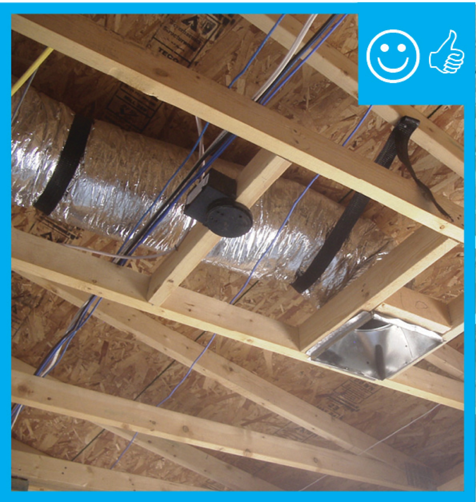
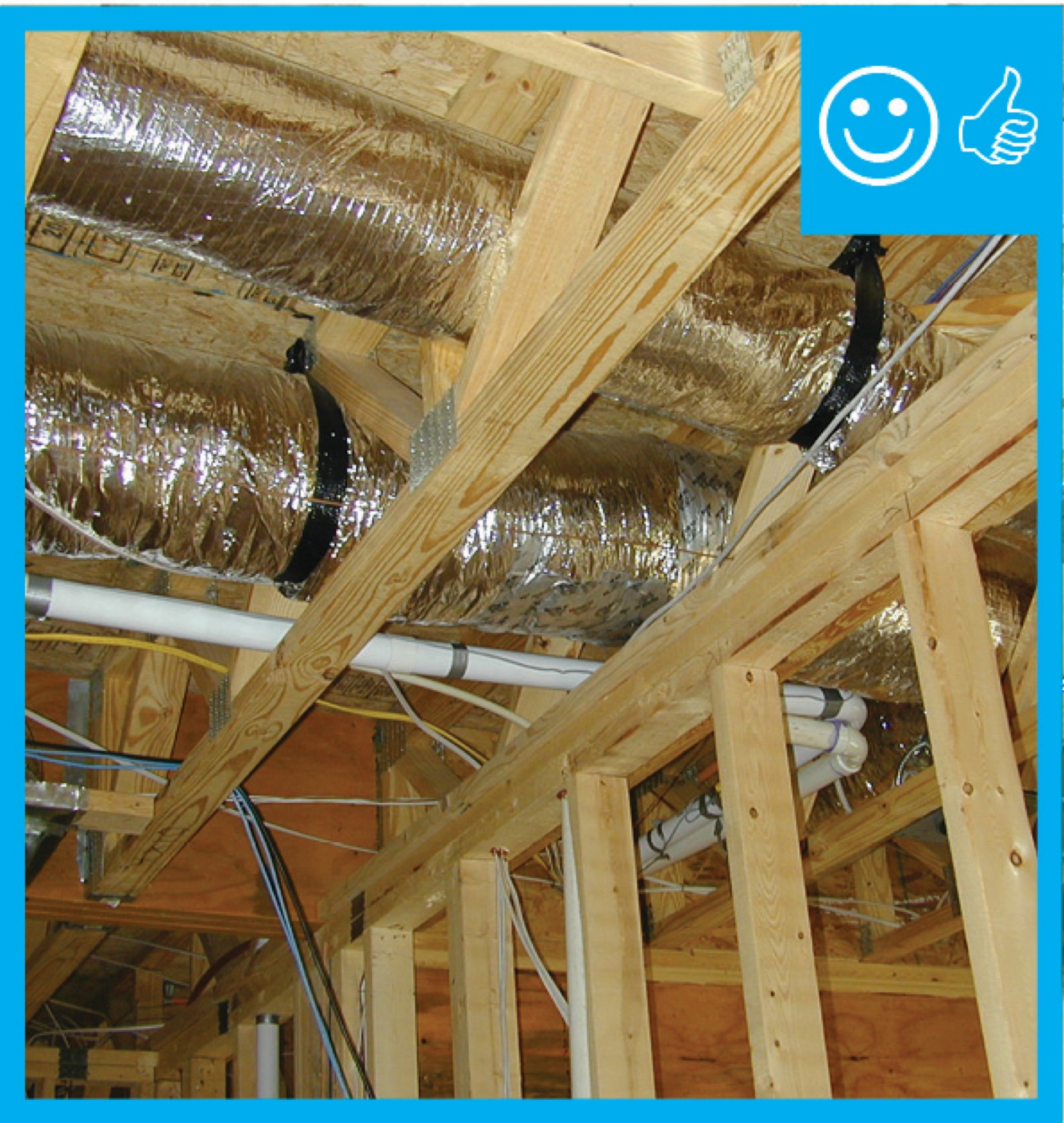
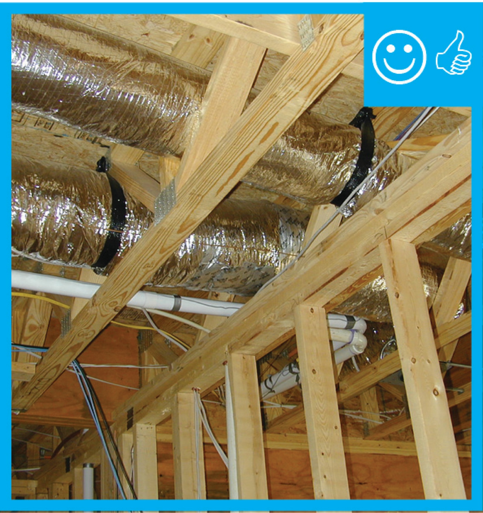
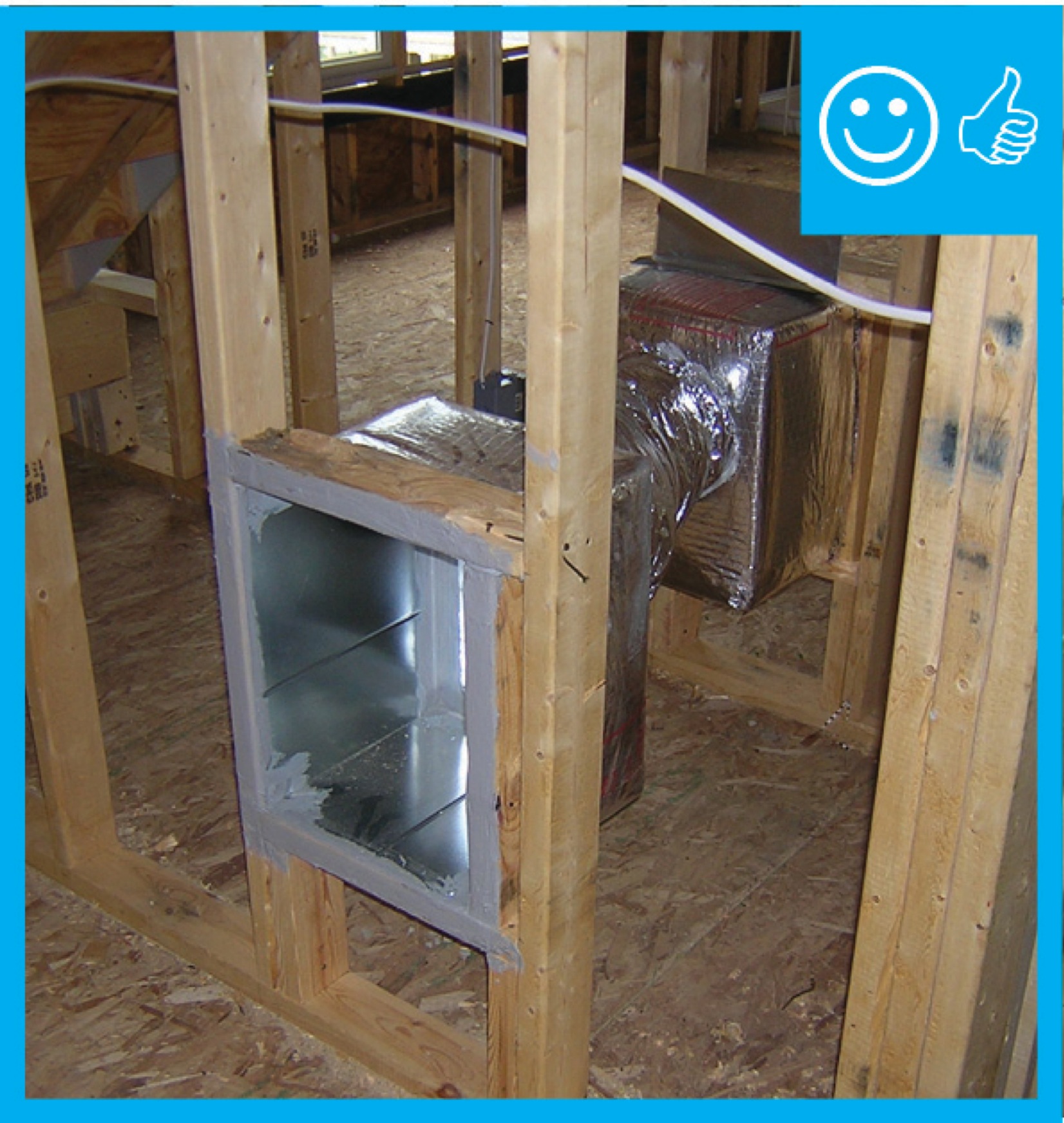
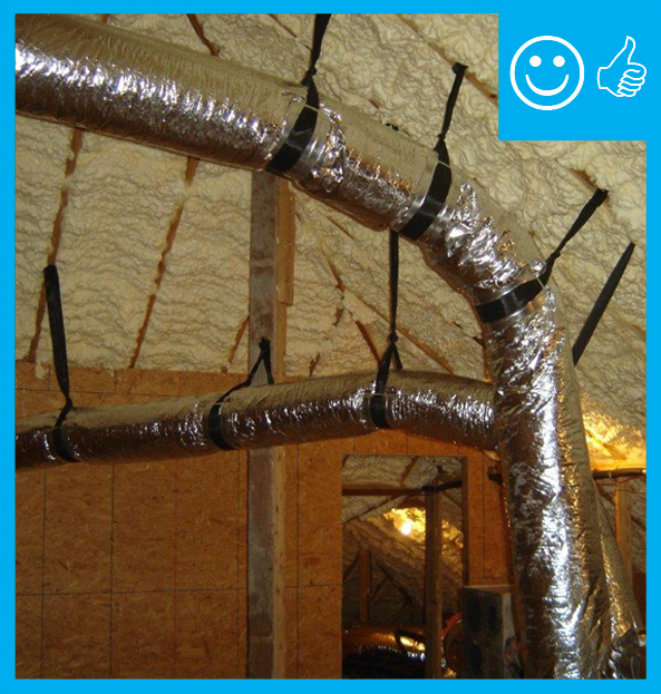
Right - Flex duct installed with frequent supports, straight runs, and gradual turns to allow good air flow
Image
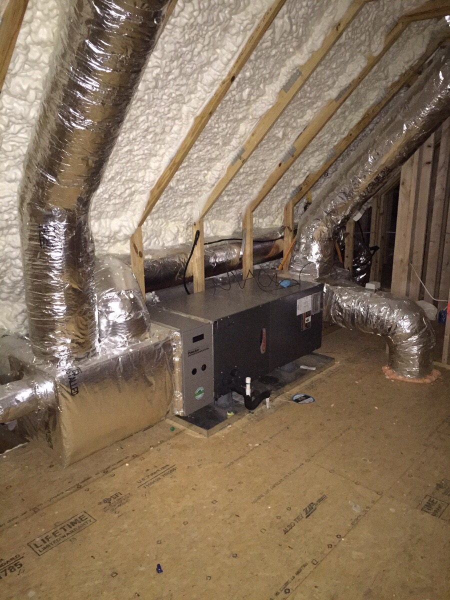
Right - Open-cell polyurethane spray foam to R-28 on underside of roof turns new attic into conditioned space for HVAC.
Image
Image
Image
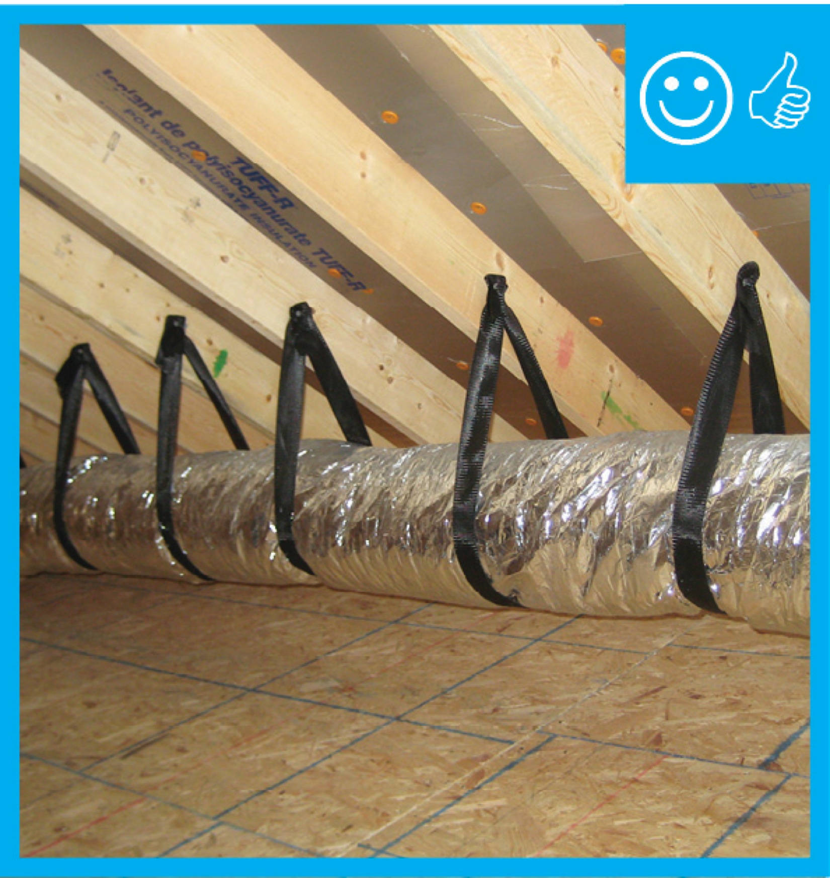
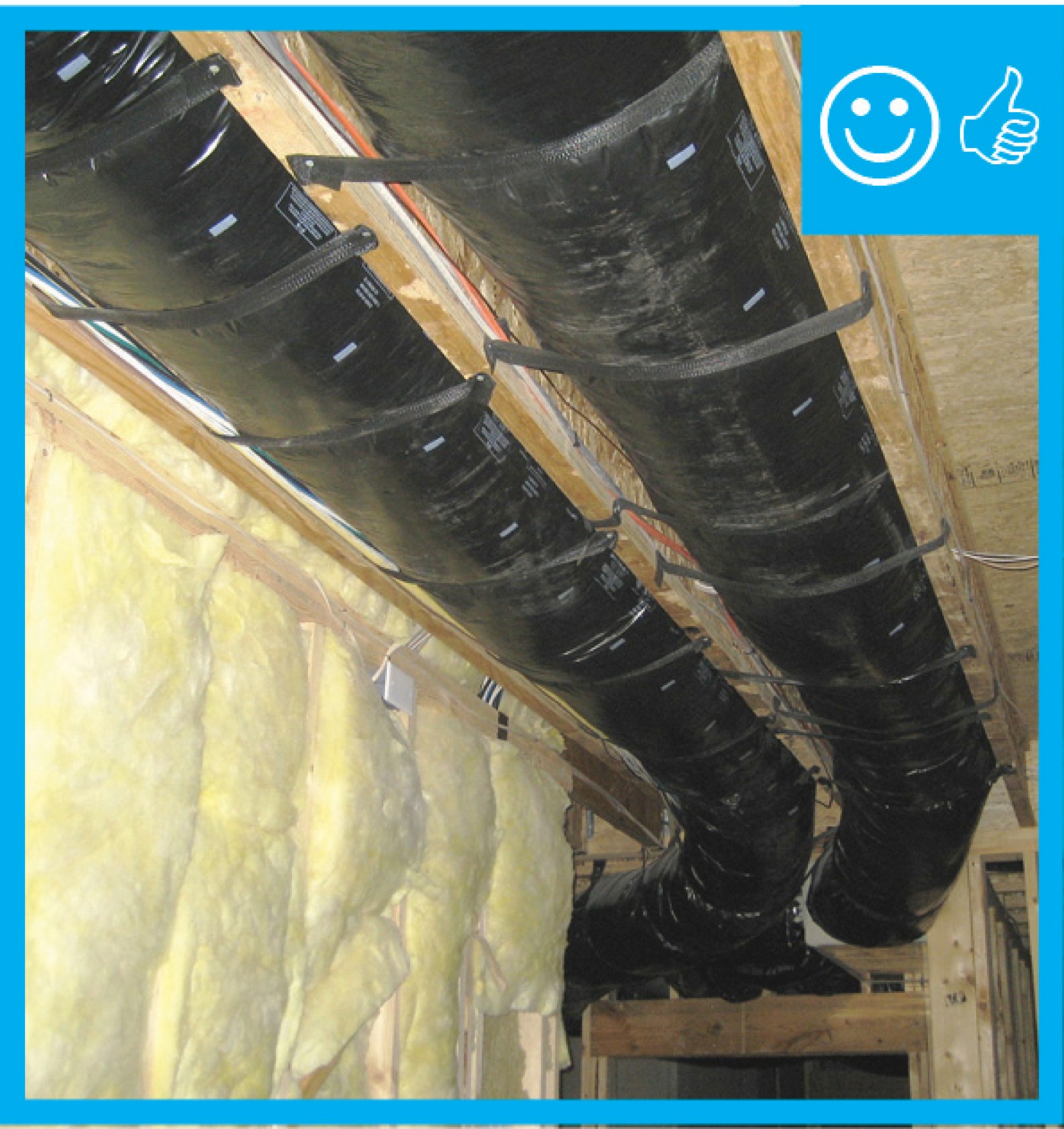
Right - Straps are spaced close enough together to provide adequate support of the flex duct
Image
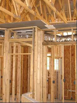
Right - The HVAC ducts are located in conditioned space in a dropped hallway ceiling with very short duct runs for more efficient delivery.
Image
Image
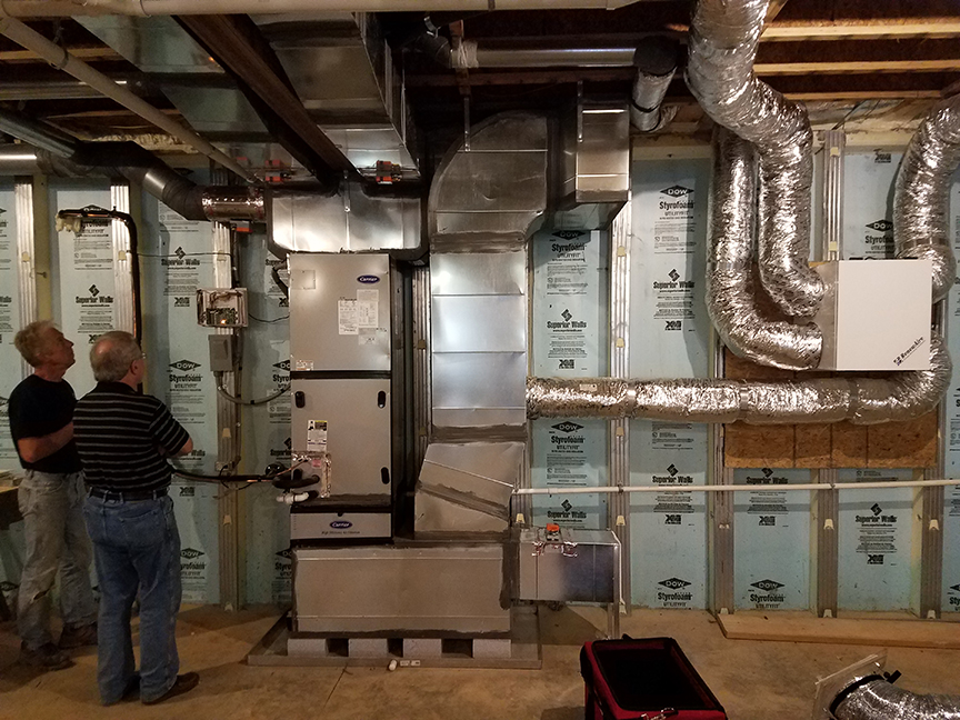
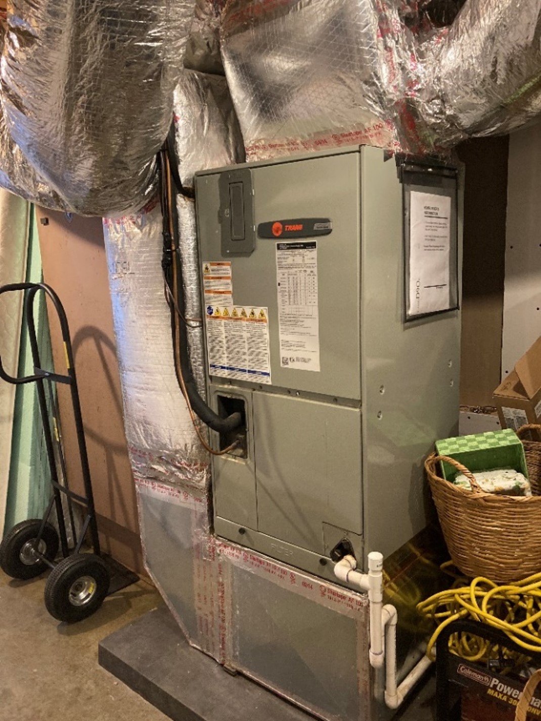
Right - The precast insulated concrete walls of the basement provide a conditioned space for the high-efficiency (18 SEER, 9.5 HSPF) air-source heat pump, with its variable-speed fan, five-stage compressor, and MERV 11 filter.
Image
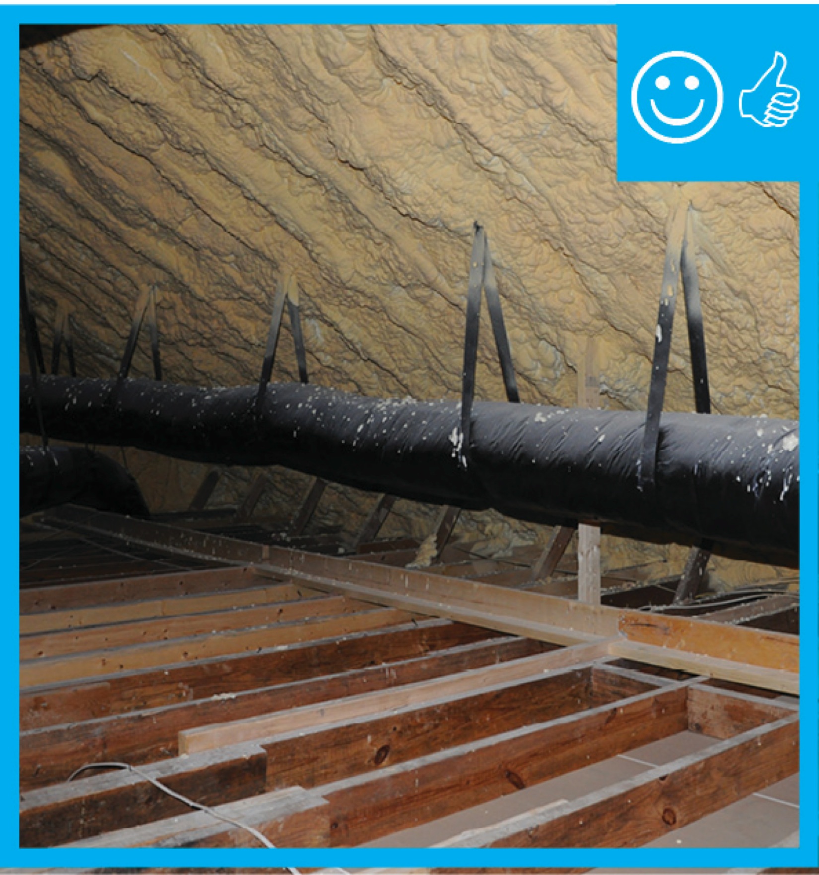
Right – Flex ducts are properly supported with straps that don’t pinch the insulation; closed-cell spray foam will be applied to the underside of the roof deck of this hot-humid climate home to provide an insulated attic space for the HVAC ducts.
Image
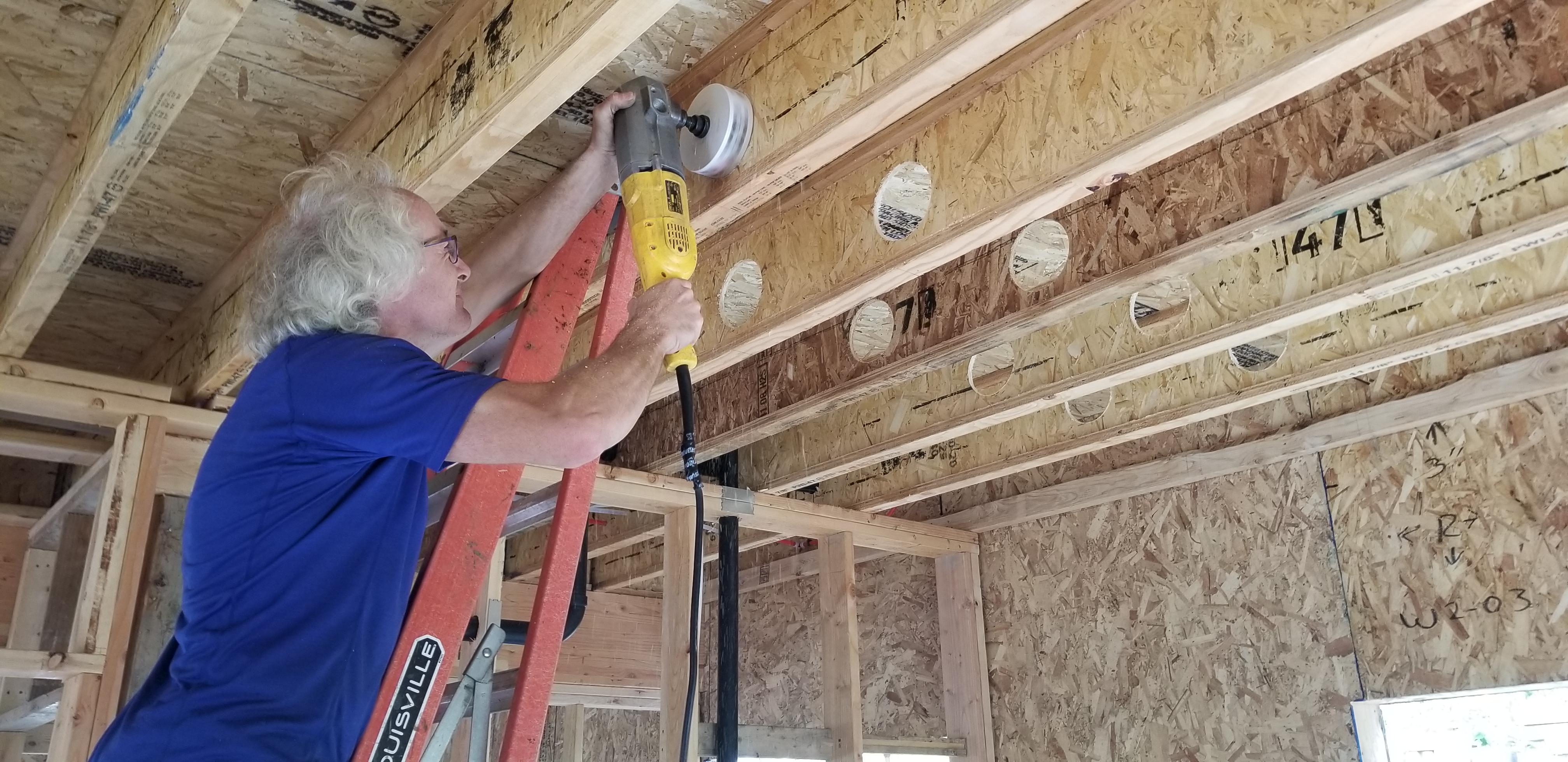
Right – Holes were drilled into the I joists between floors to run the small-diameter HRV ducts.
Image
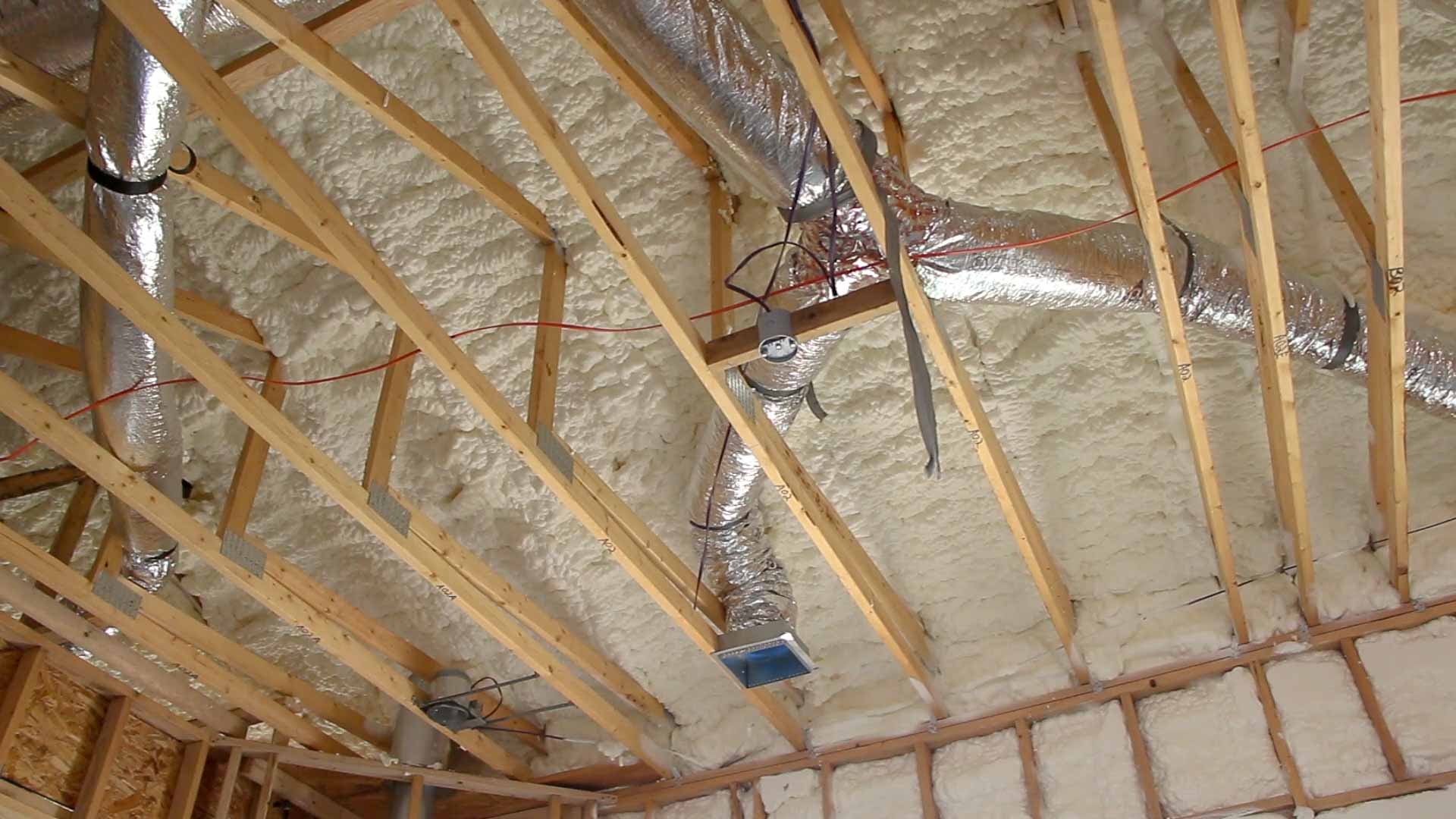
Right – R-25 of open-cell spray foam lines this new home’s attic ceiling, to protect HVAC ducts from heat and cold.
Image
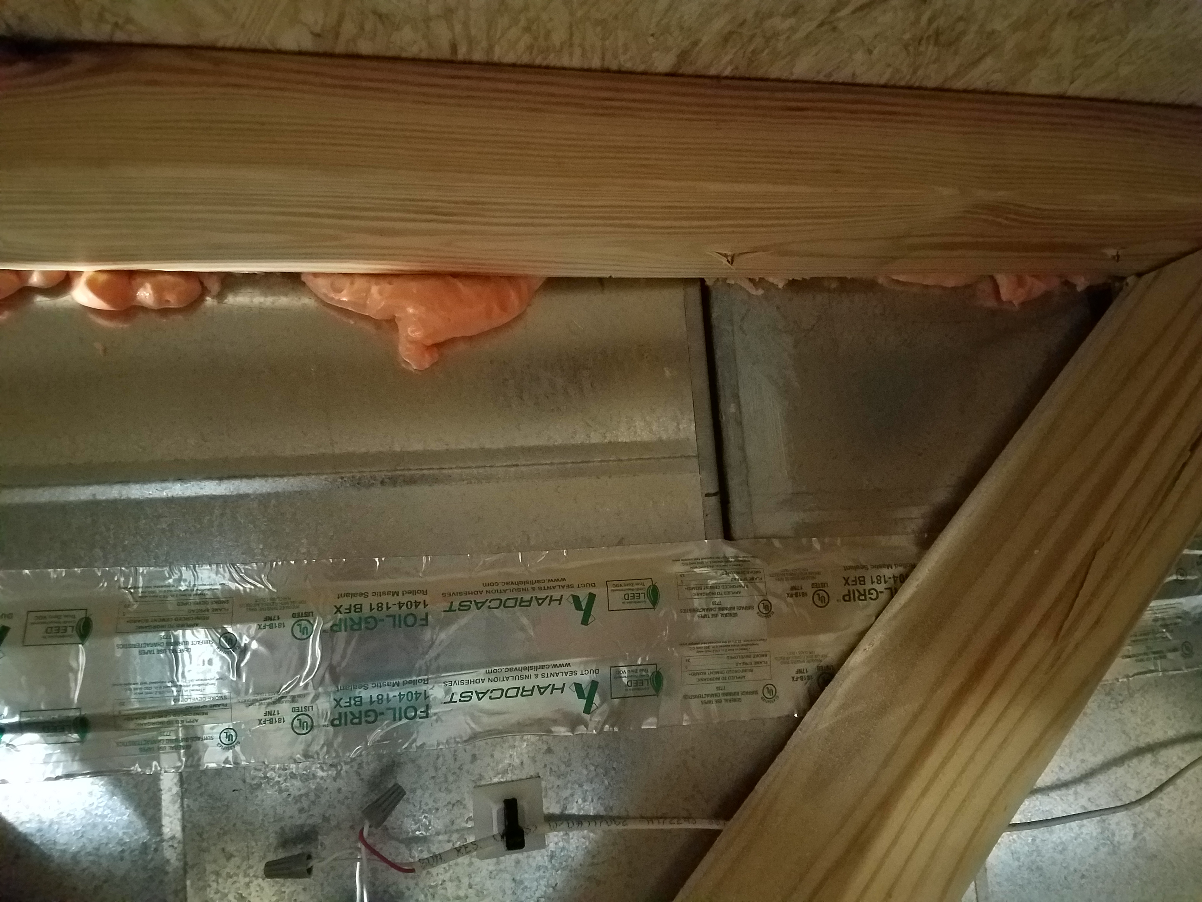
Right – Rigid foam is installed behind HVAC ducts to provide additional insulation to the ducts which are installed within the conditioned space.
Image
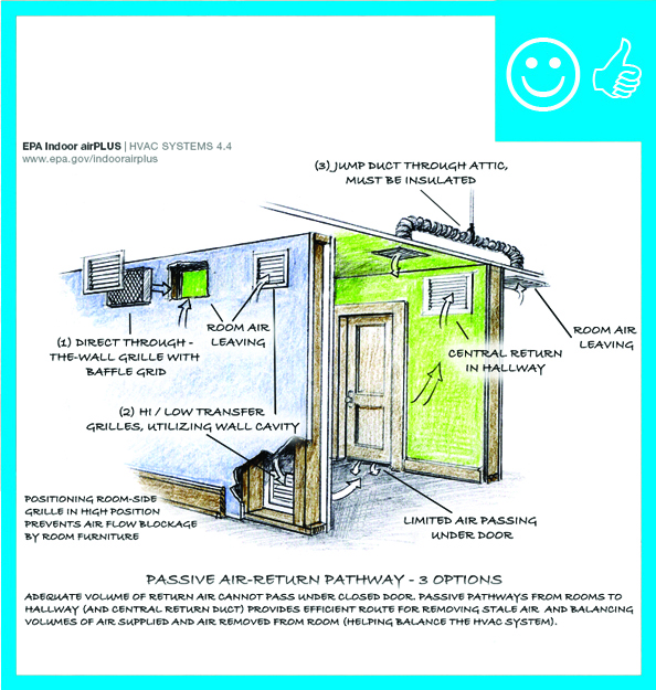
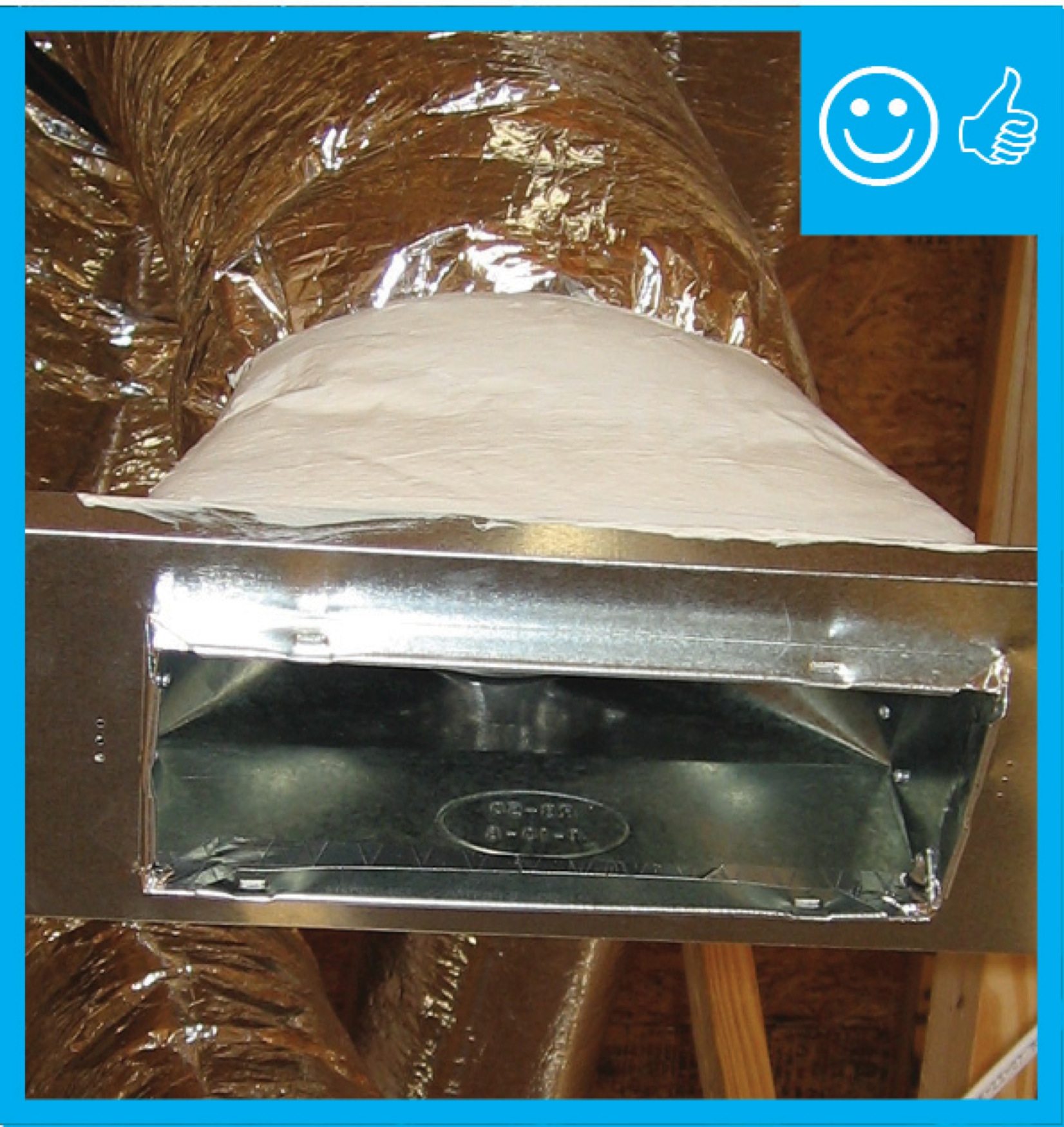
Right – Transfer grilles, Jump ducts, and wall grilles provide passive returns for air returning from bedrooms to the central HVAC system
Image
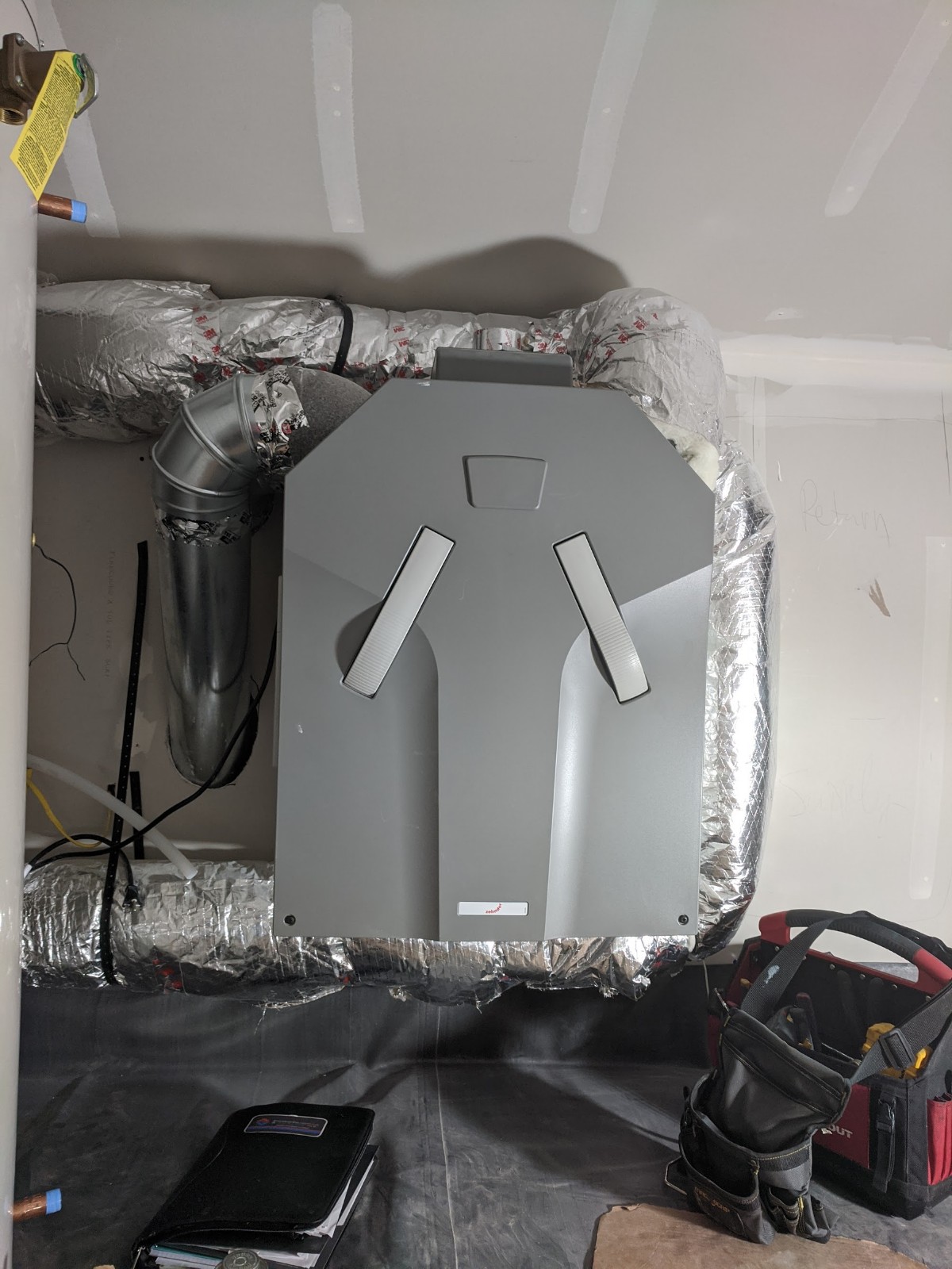
Right: A well-constructed air handler closet
Image

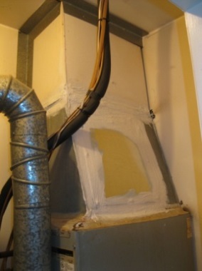
Right: Air seal all seams in the return air plenum before installing a new air handler
Image
Right: If existing straps are narrower than 1.5 inches, add sheet metal saddles to keep the duct from sagging and pinching
Image
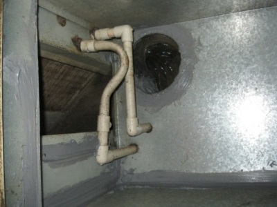
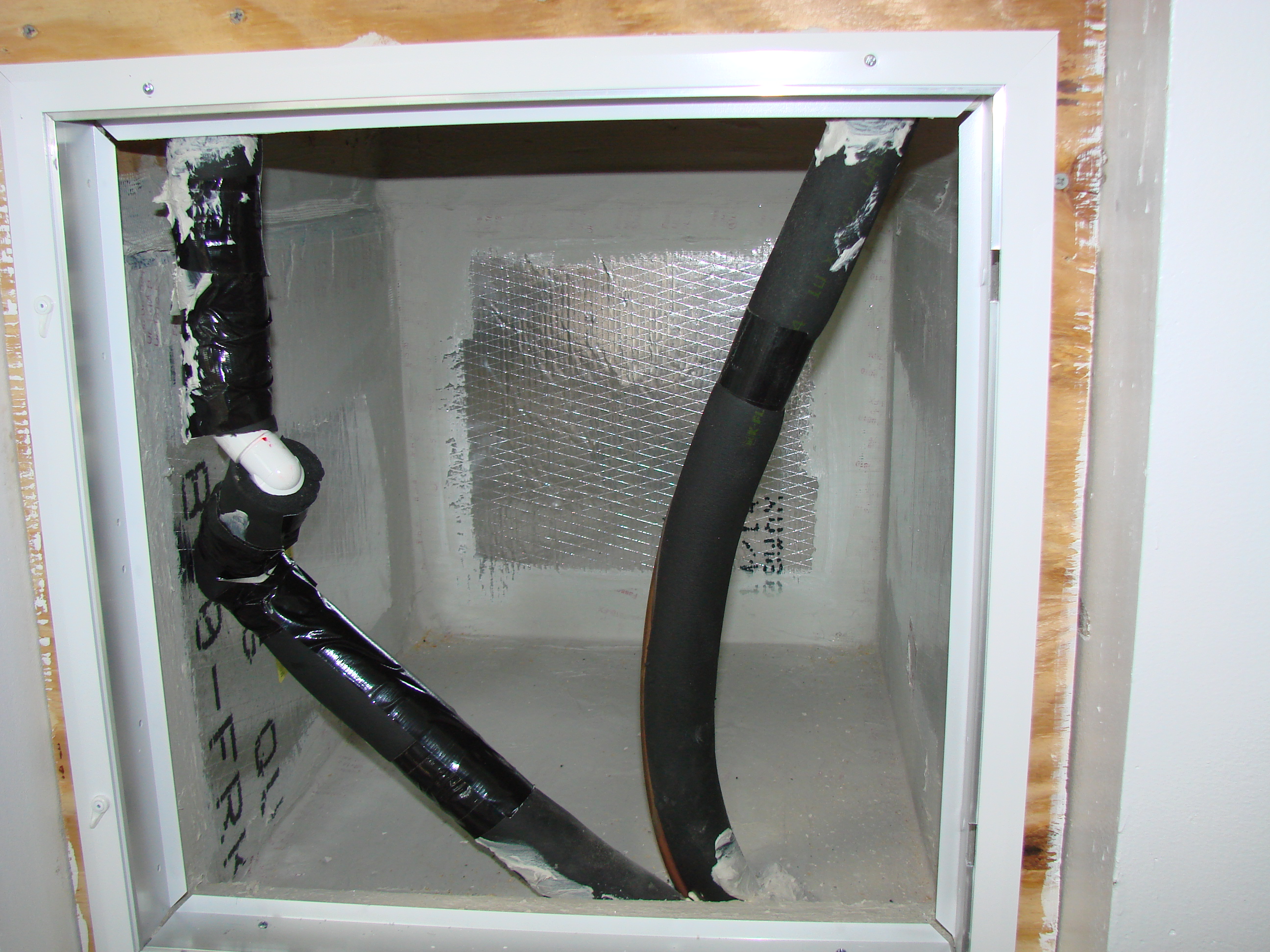
Right: Refrigerant piping is sealed where it exits the return plenum
Image
Right: The bottom of the air handler cabinet is well sealed to the return platform
Image
Right: The plenum liner is well sealed to the filter-backed grille
Image
Right: Use mastic to air seal the return air plenum and to seal around refrigerant lines coming from the slab in the floor of the return
Image
Image
Image
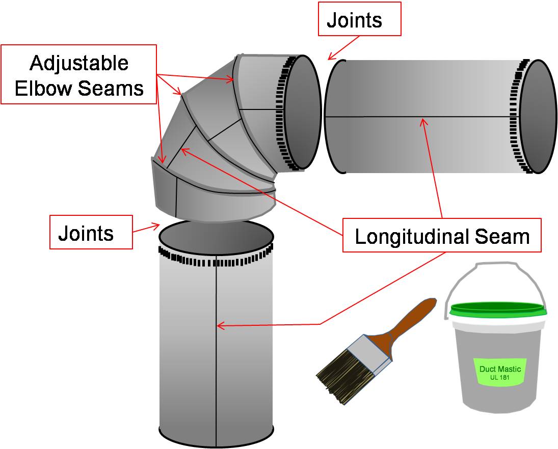
Seal all joints and seams in the metal ductwork with mastic before installing insulation
Image
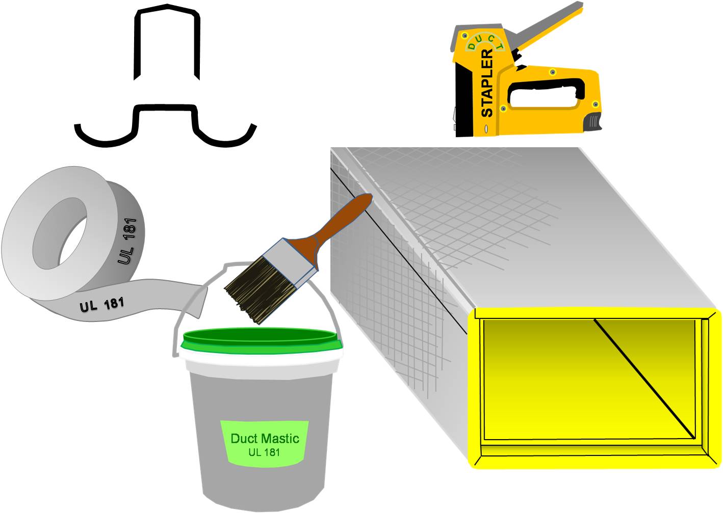
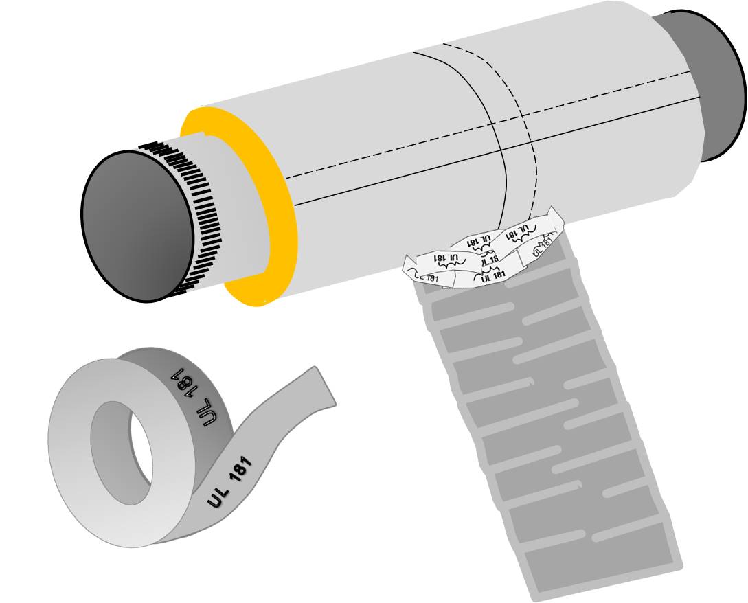
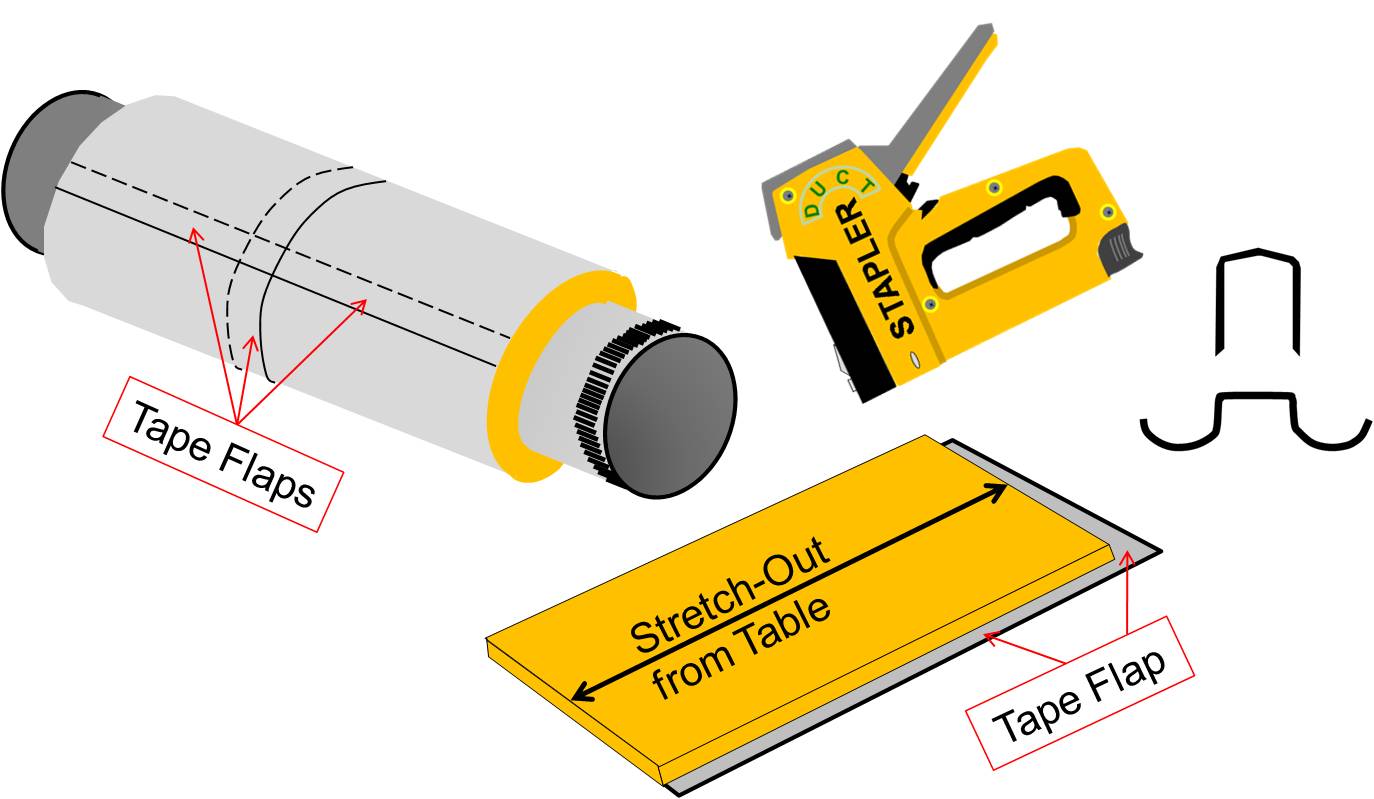
Seal seams in fiber board ducts with out-clinching staples, UL-181A-approved tape, and mastic
Image
Image
Seperate dwellings with their own seperate exhaust terminations
Image
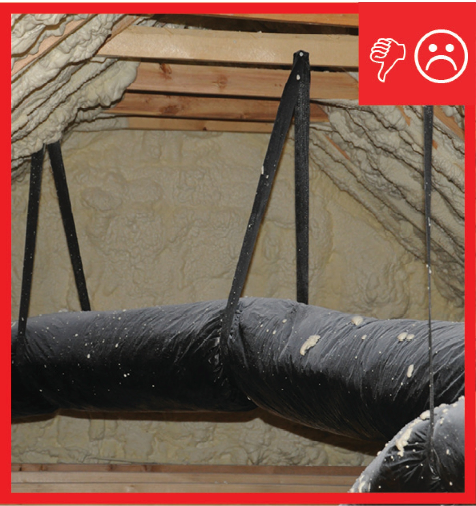
Straps are spaced too far apart causing the straps to compress the duct under its own weight
Image

The AC unit has a drip pan and automatic shutoff in case the condensate drain gets clogged.
Image
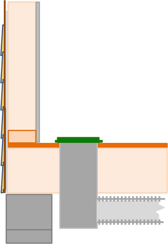
The drywall above the dropped ceiling duct chase extends beyond adjoining top plates for a continuous air barrier
Image
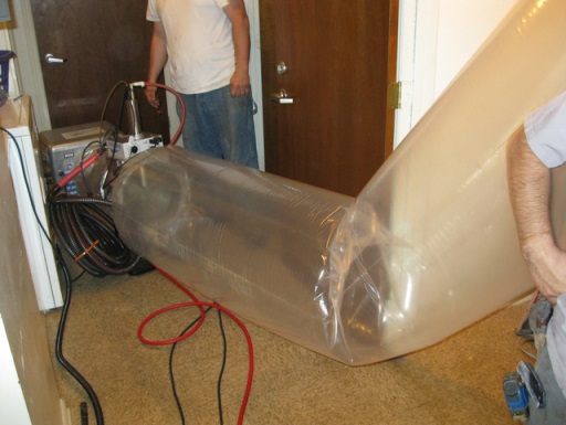
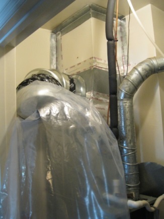
The duct sealing spray injection system application tunnel inflates as the injection system operates
Image
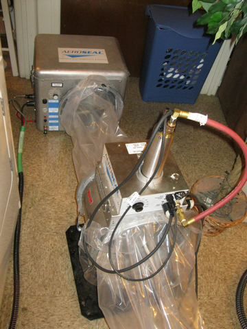
The duct sealing spray injection system includes a blower/heater (background) and the sealant injection unit (foreground)
Image
Image
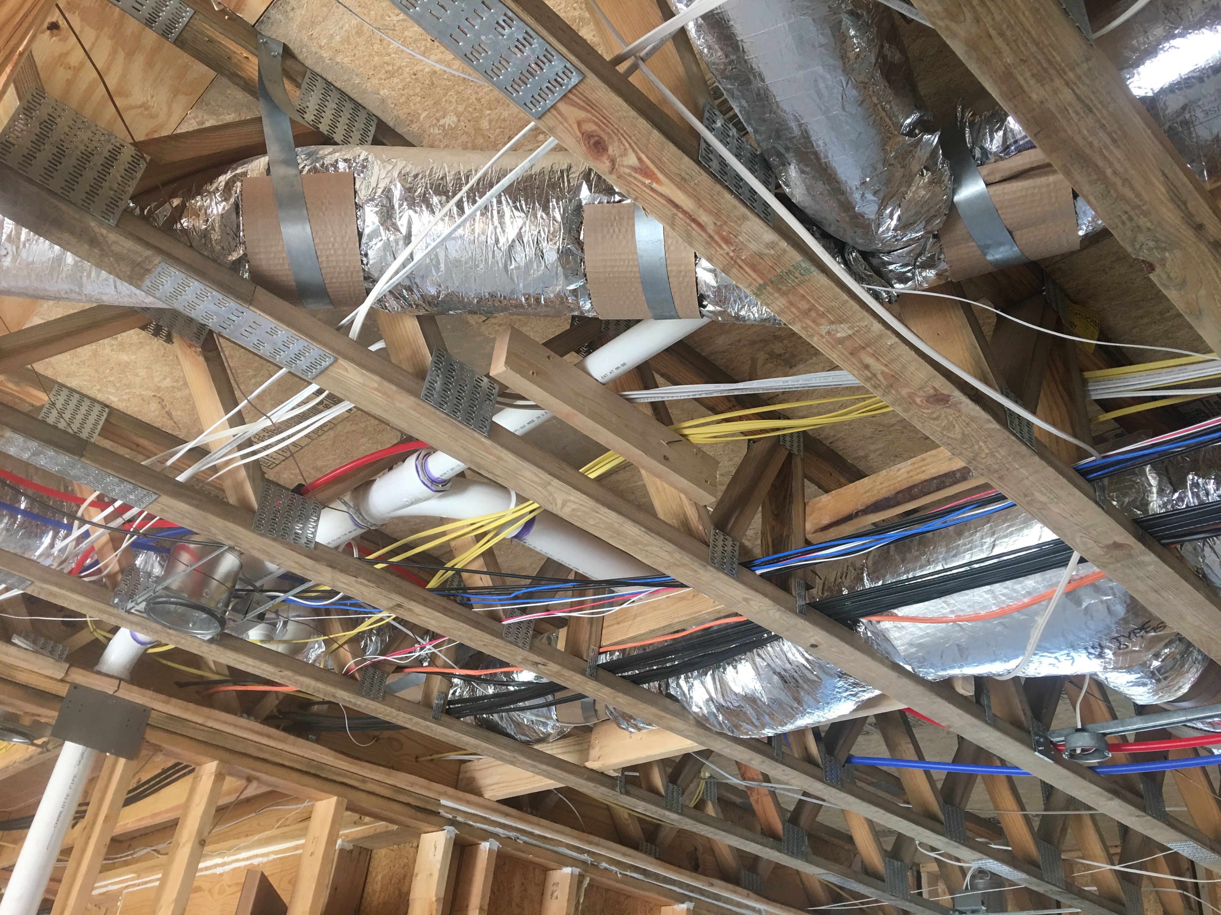
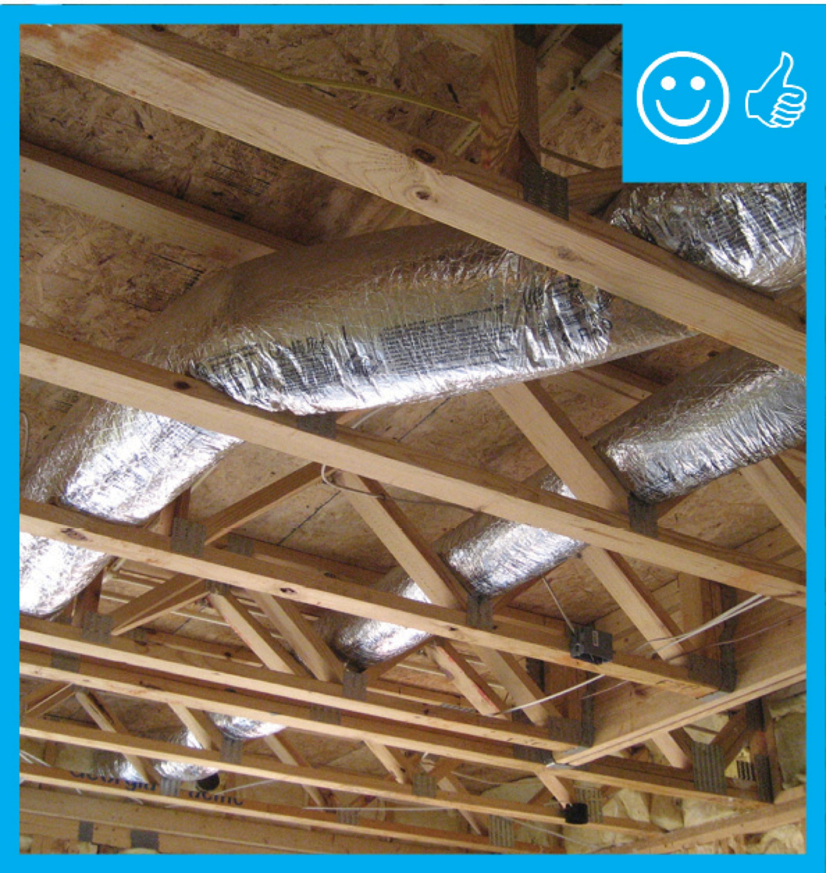
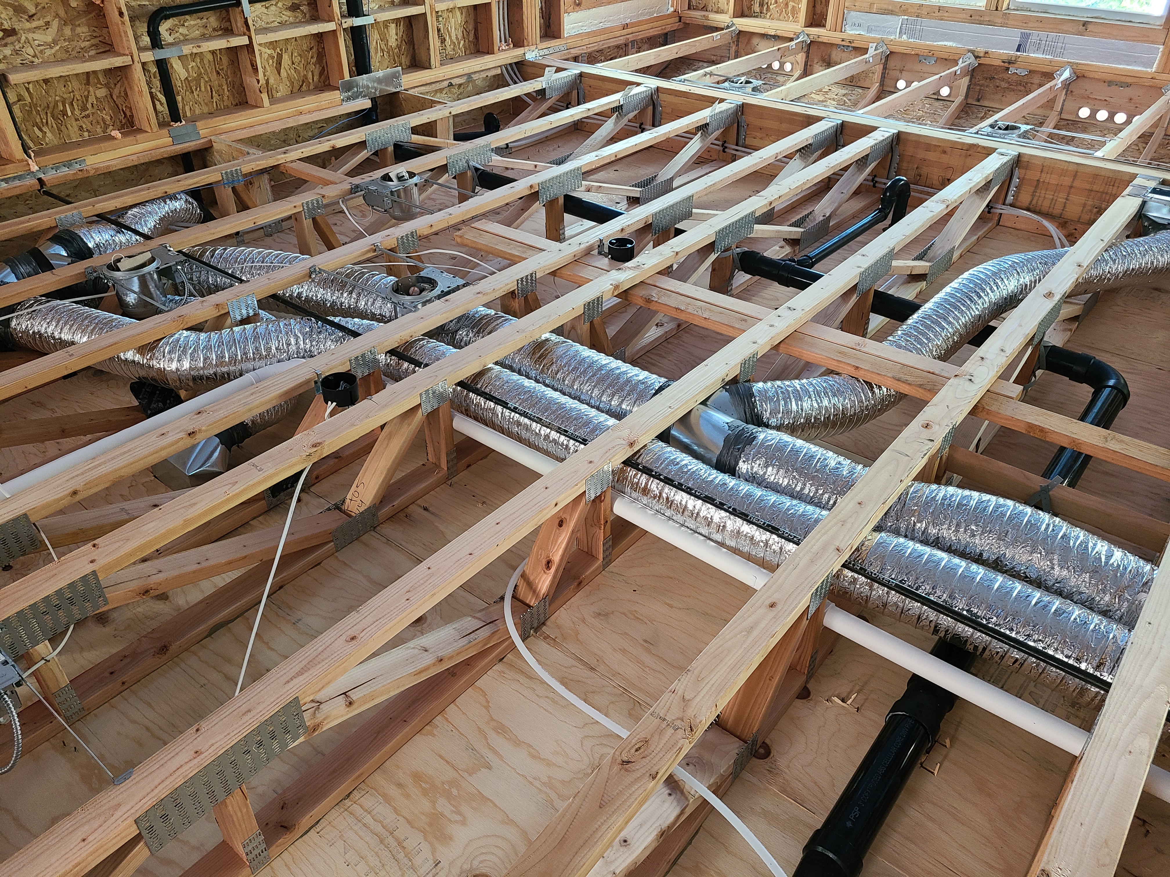
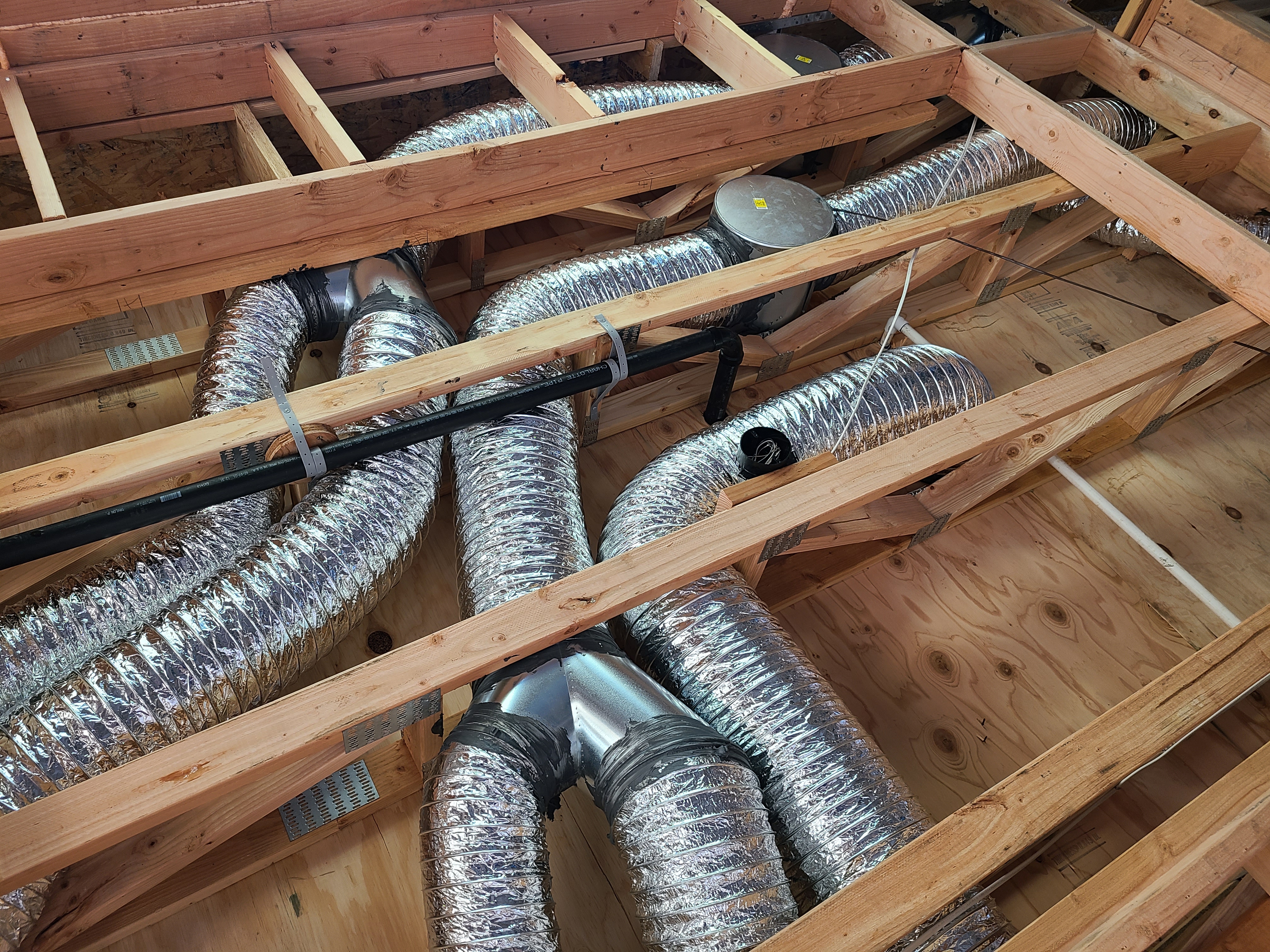
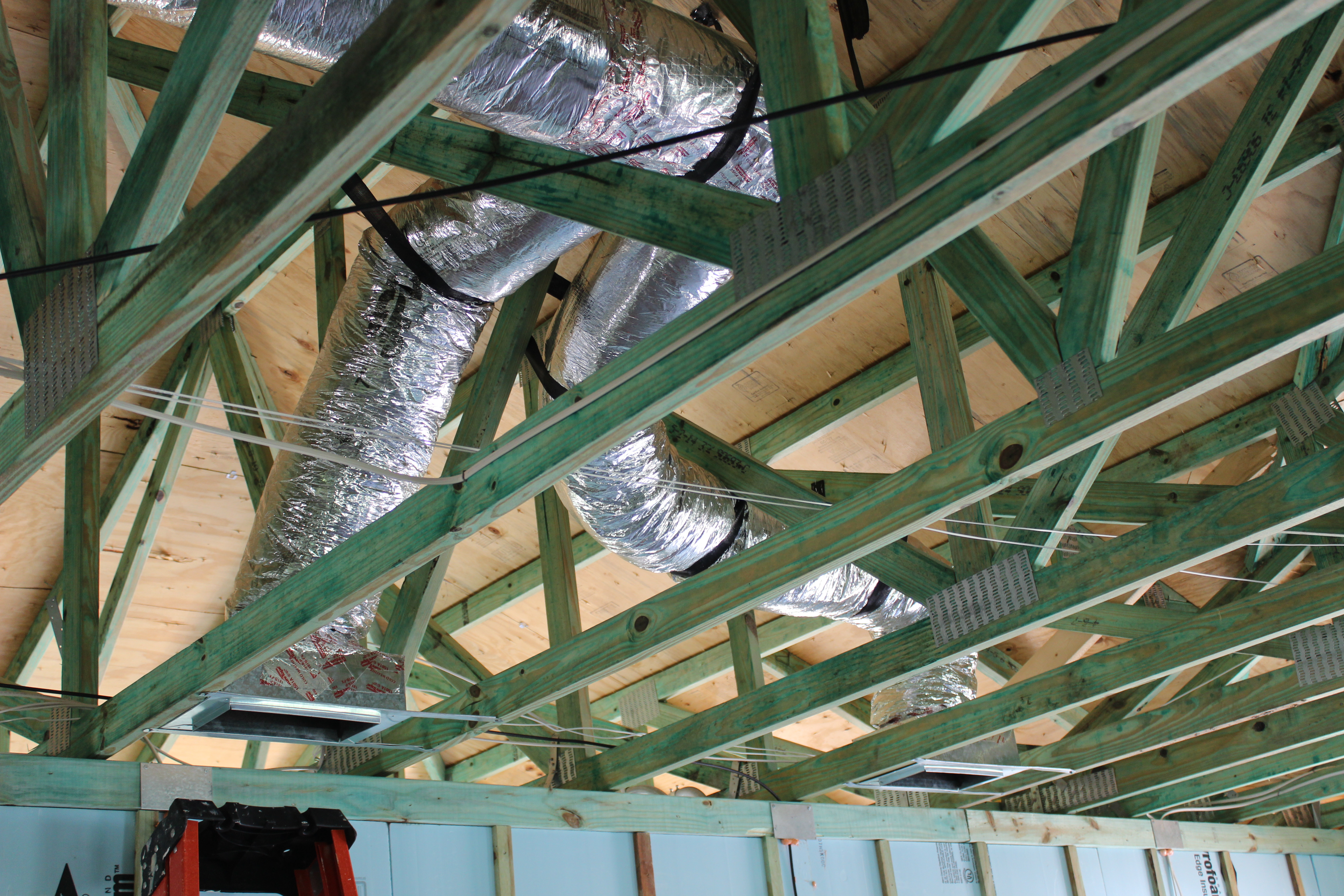
The ducts are located in conditioned space in open-web joists between the floors and supported to prevent sagging.
Image
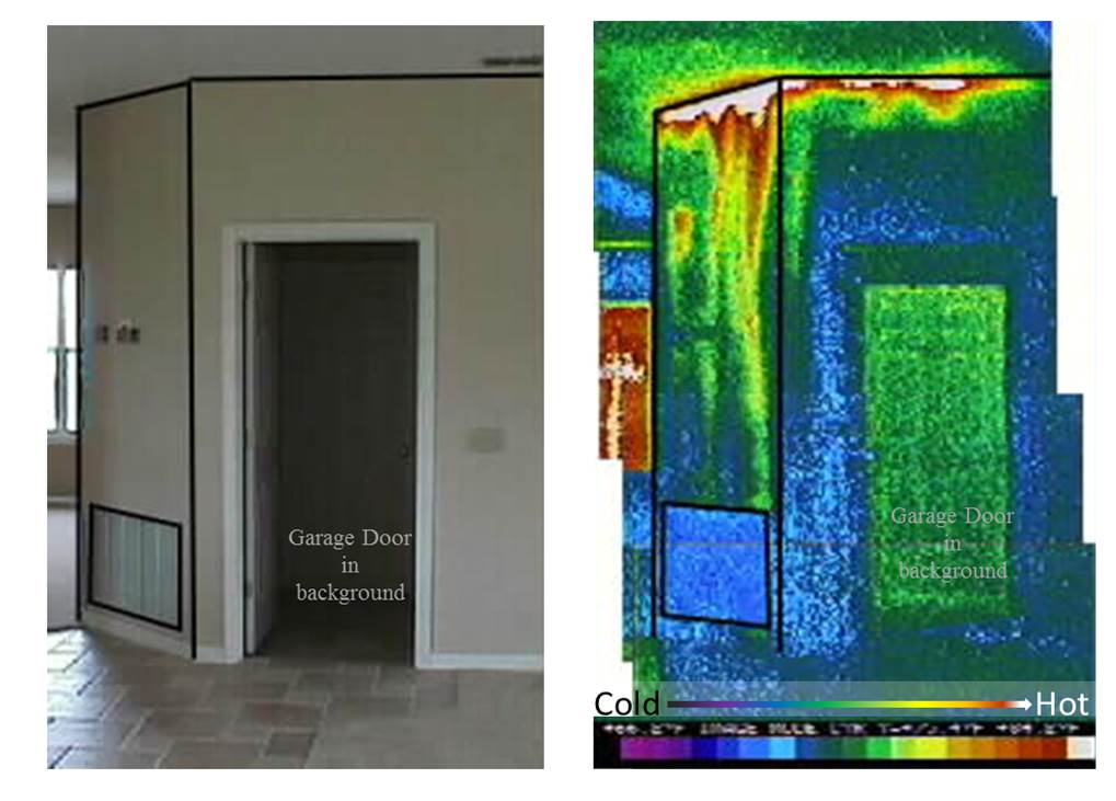
The grille in the photo on the left brings air into a return air plenum under an air handler platform. As shown in the infrared image on the right, the plenum is not air sealed so hot attic air is being pulled into the air handler closet.
Image
Image
The high-efficiency air-to-air heat pump is set in an overflow pan with an emergency shut off sensor in case the condensate tube were to clog and cause condensate to fill up the pan.
Image
Image
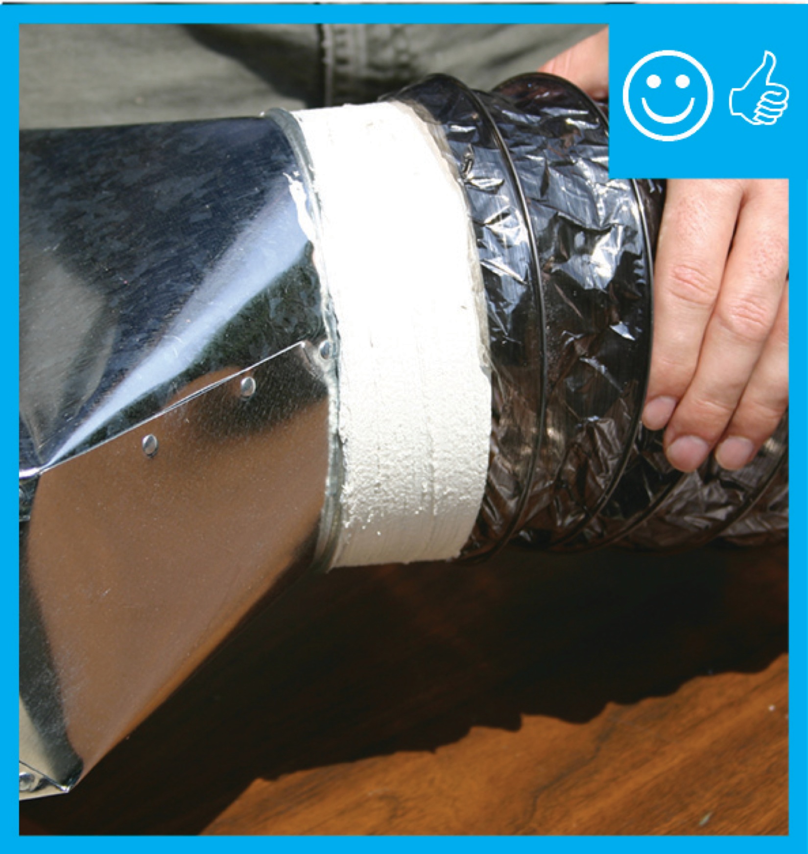
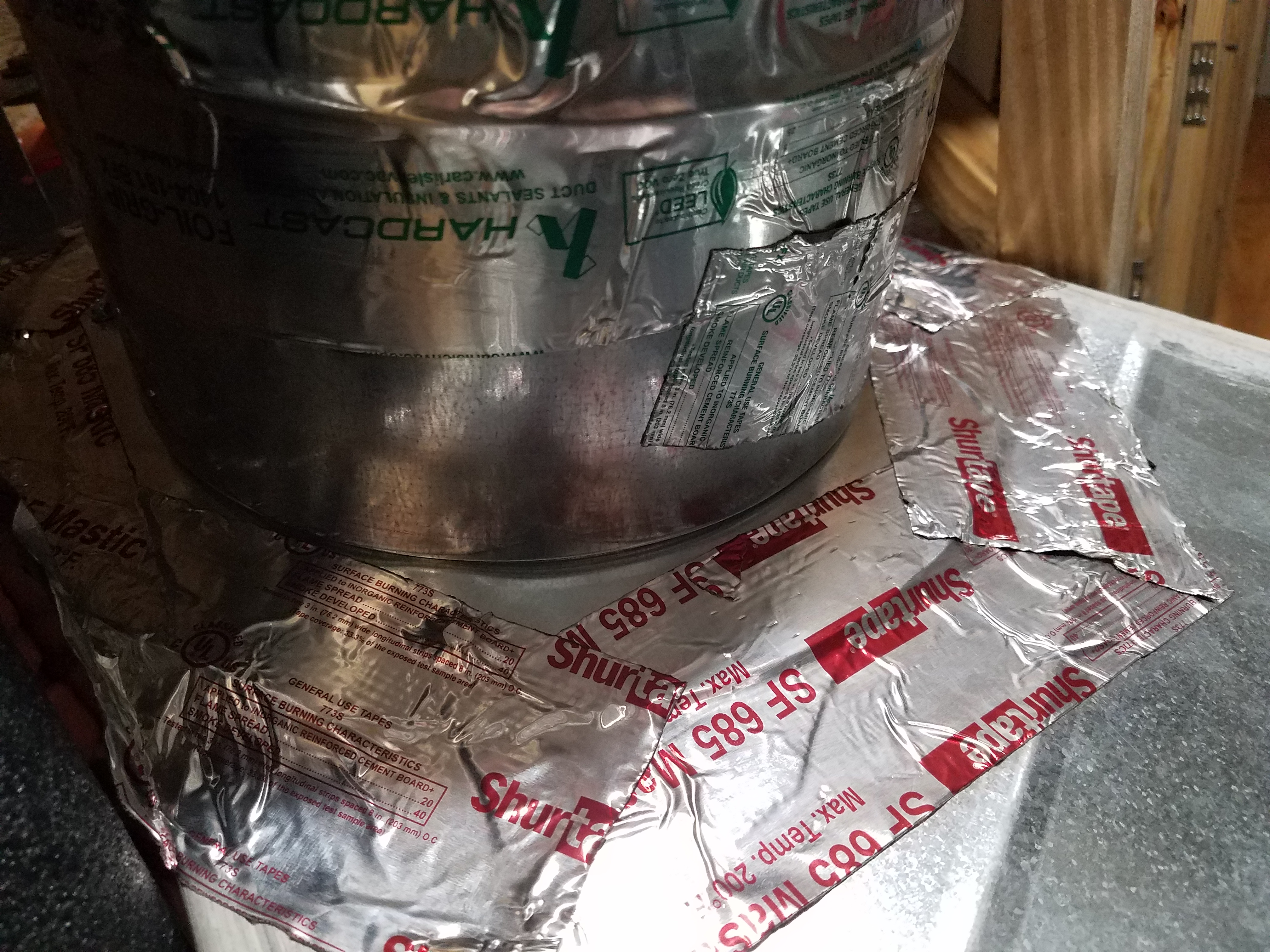
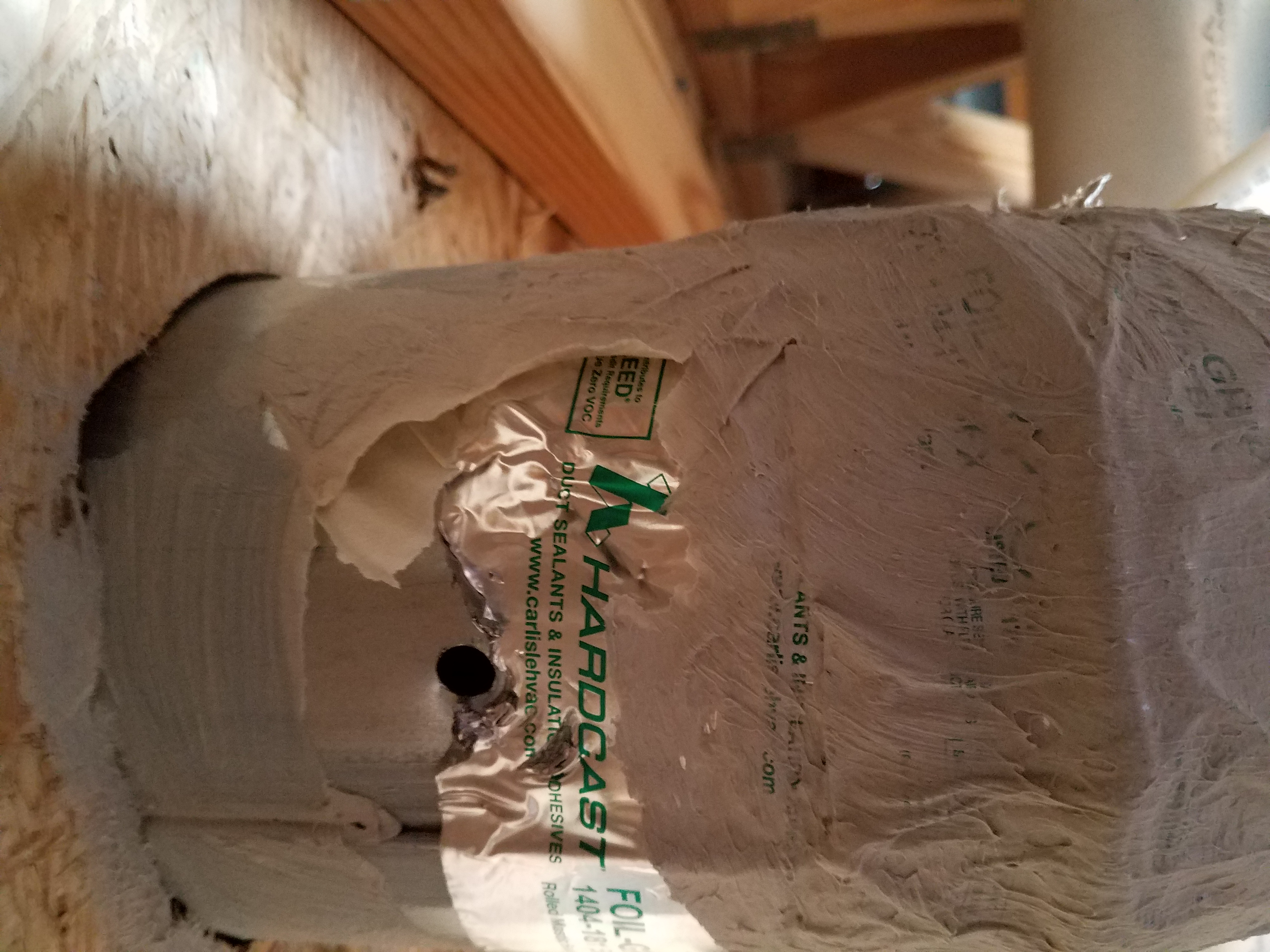
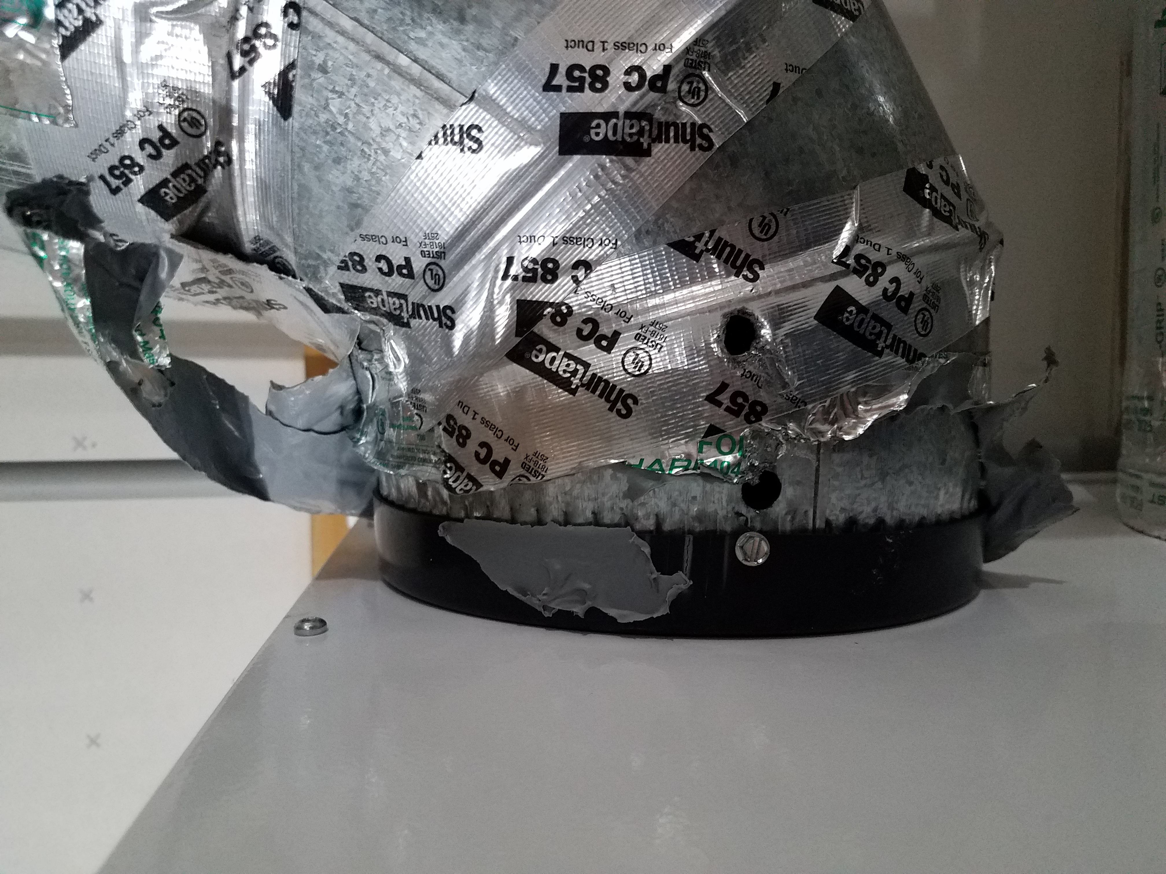
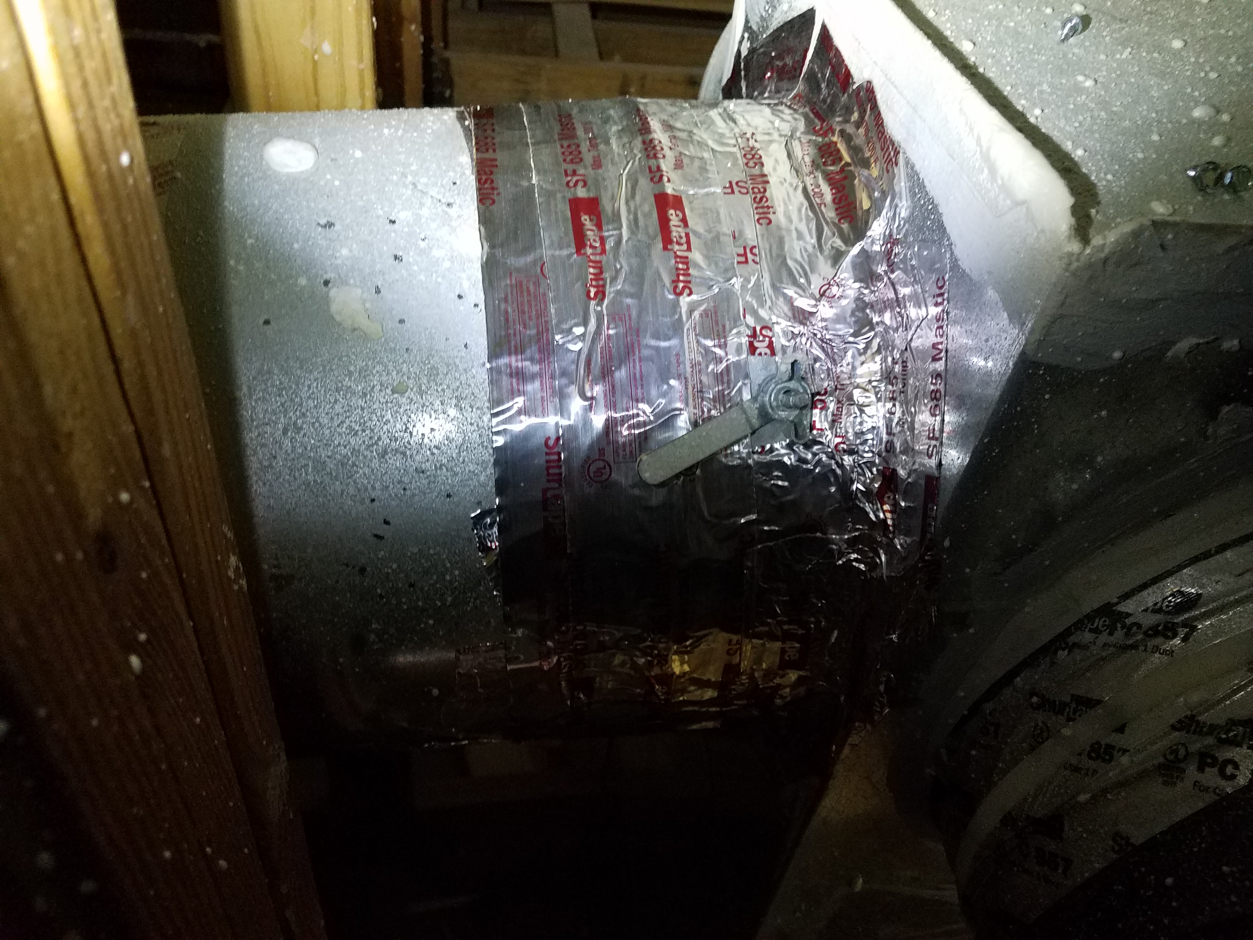
The tape is covered with mastic to ensure an airtight seal between the duct and the fitting
Image
These ducts were installed within the home's conditioned space in a central chaise down the main hallway.
Image
This “high static ducted cassette” heat pump system is similar to a traditional centrally ducted system, serving several areas of a home from one indoor unit
Image

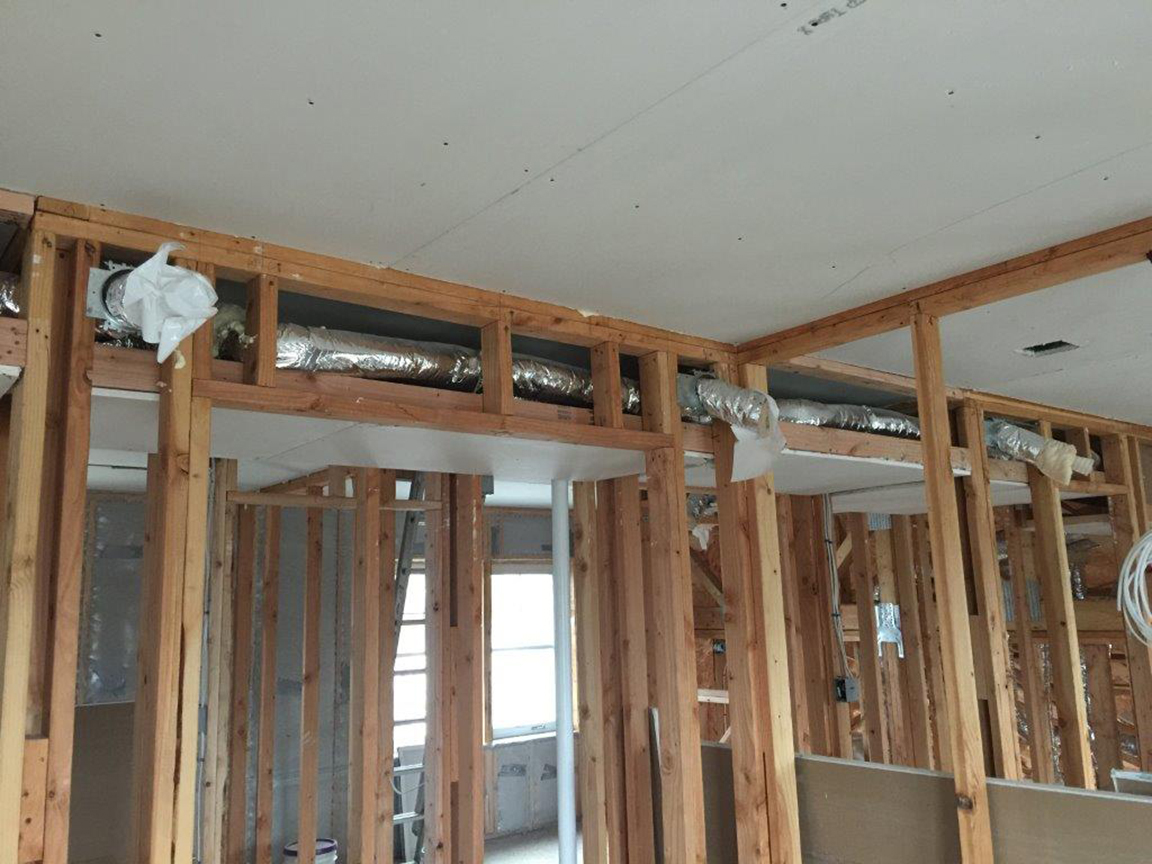
This dropped soffit runs the length of the house providing a convenient place to locate one trunk duct with several very short side ducts that supply heat and cooling to most rooms of the house.
Image
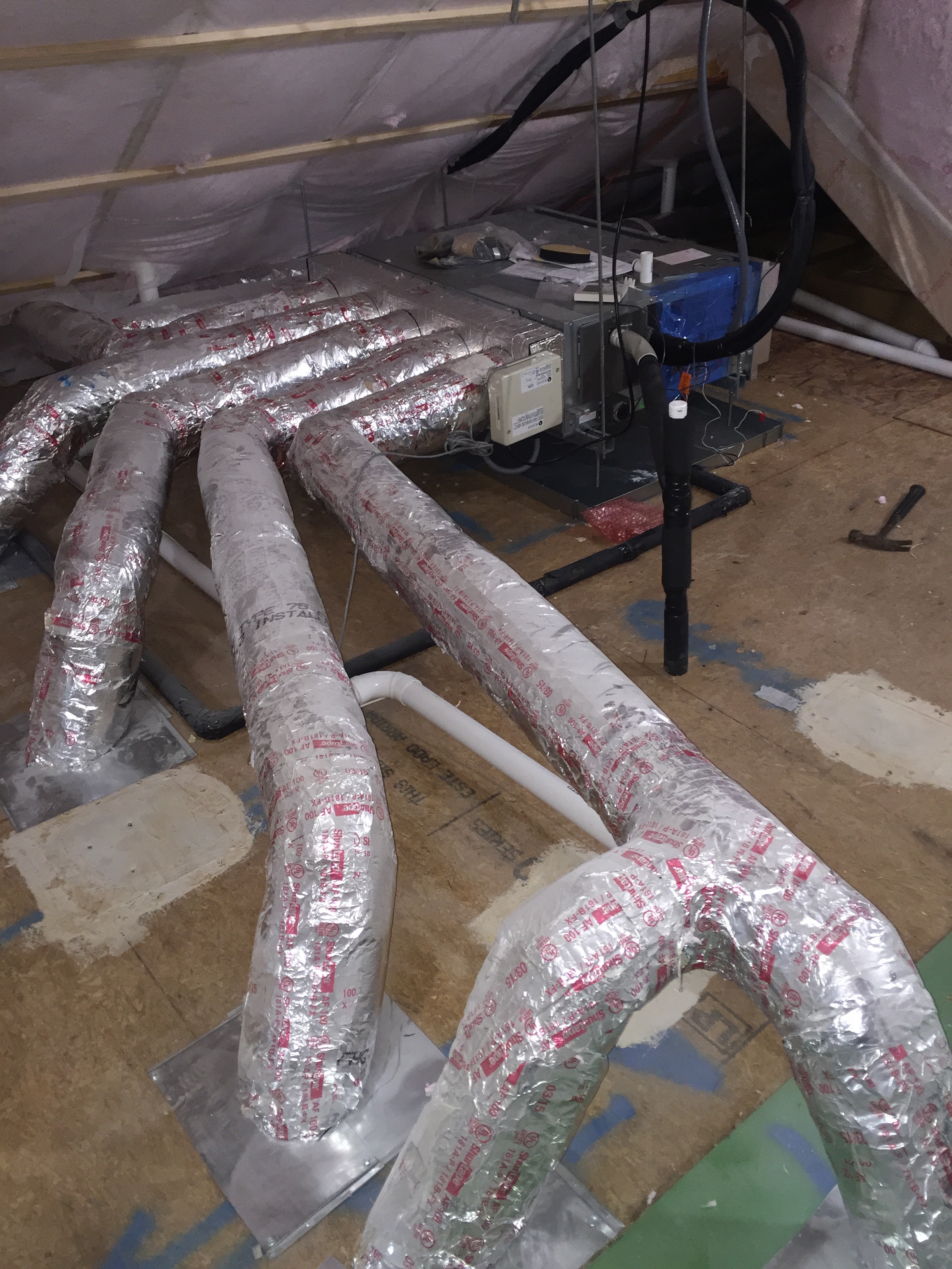
This ducted mini-split heat pump was installed in the unvented, conditioned attic and ducted with short duct runs to several nearby rooms.
Image
This home’s ultra-efficient ground-source heat pump provides hot water for space heating as well as domestic hot water for the 50-gallon storage tank.
Image
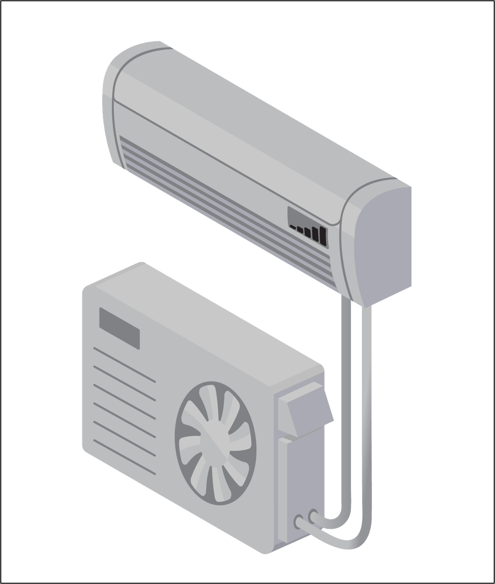
This single-zone mini-split ductless heat pump has only one indoor wall-mounted unit and one outdoor unit.
Image
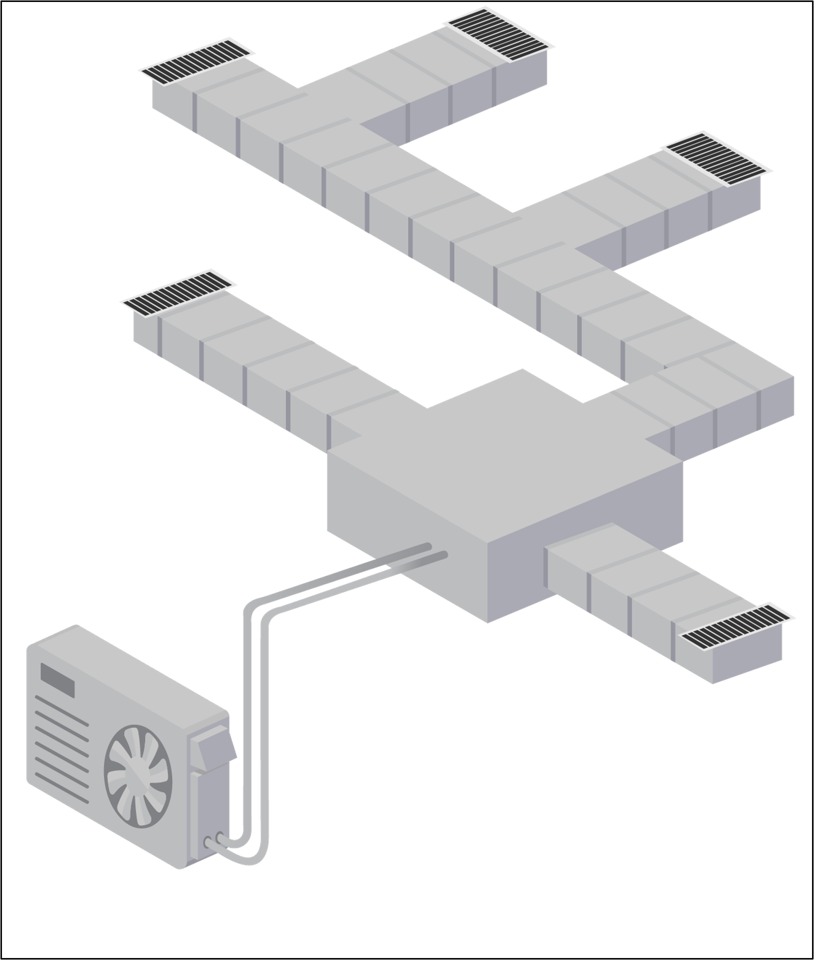
This traditional centrally ducted heat pump heats and cools the entire home through a network of ducts.
Image

This typical dropped ceiling hallway chase shows a complicated air sealing scheme where chase ceiling drywall meets sidewall top plates
Image
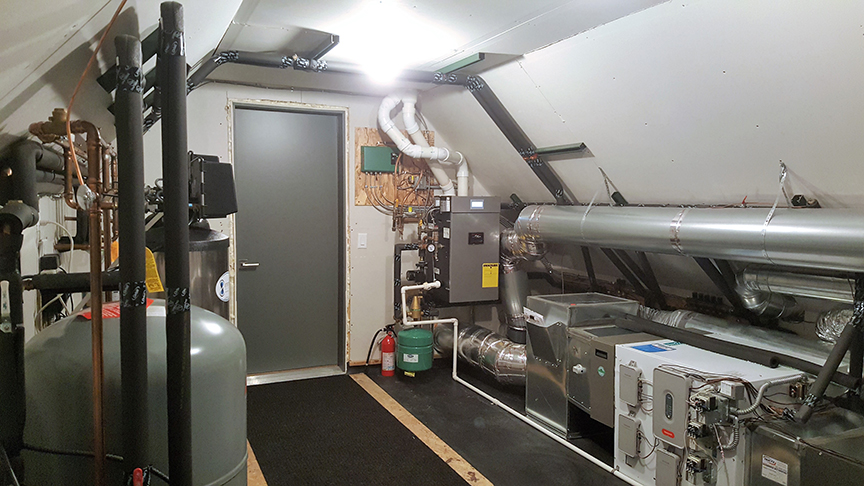
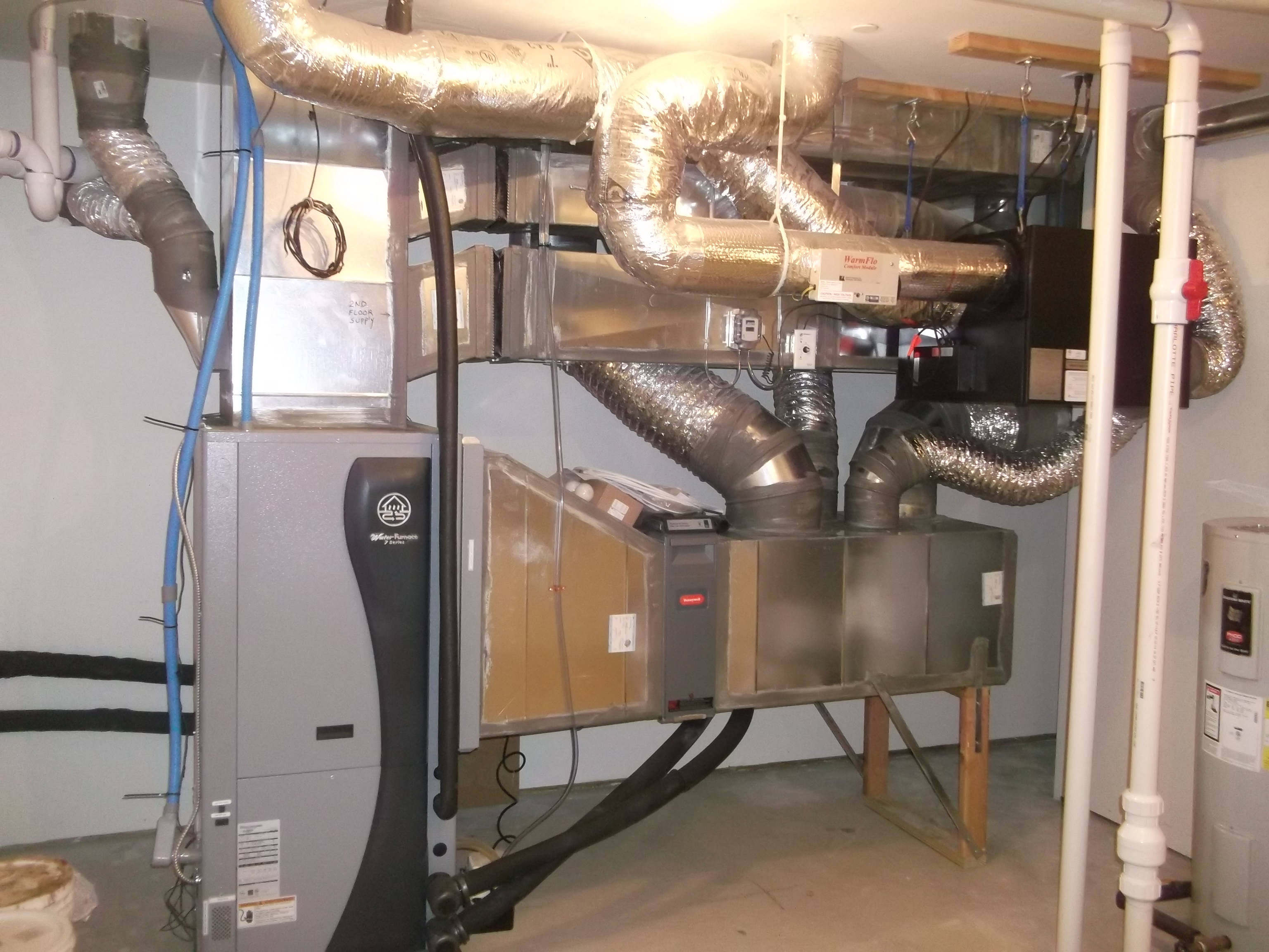
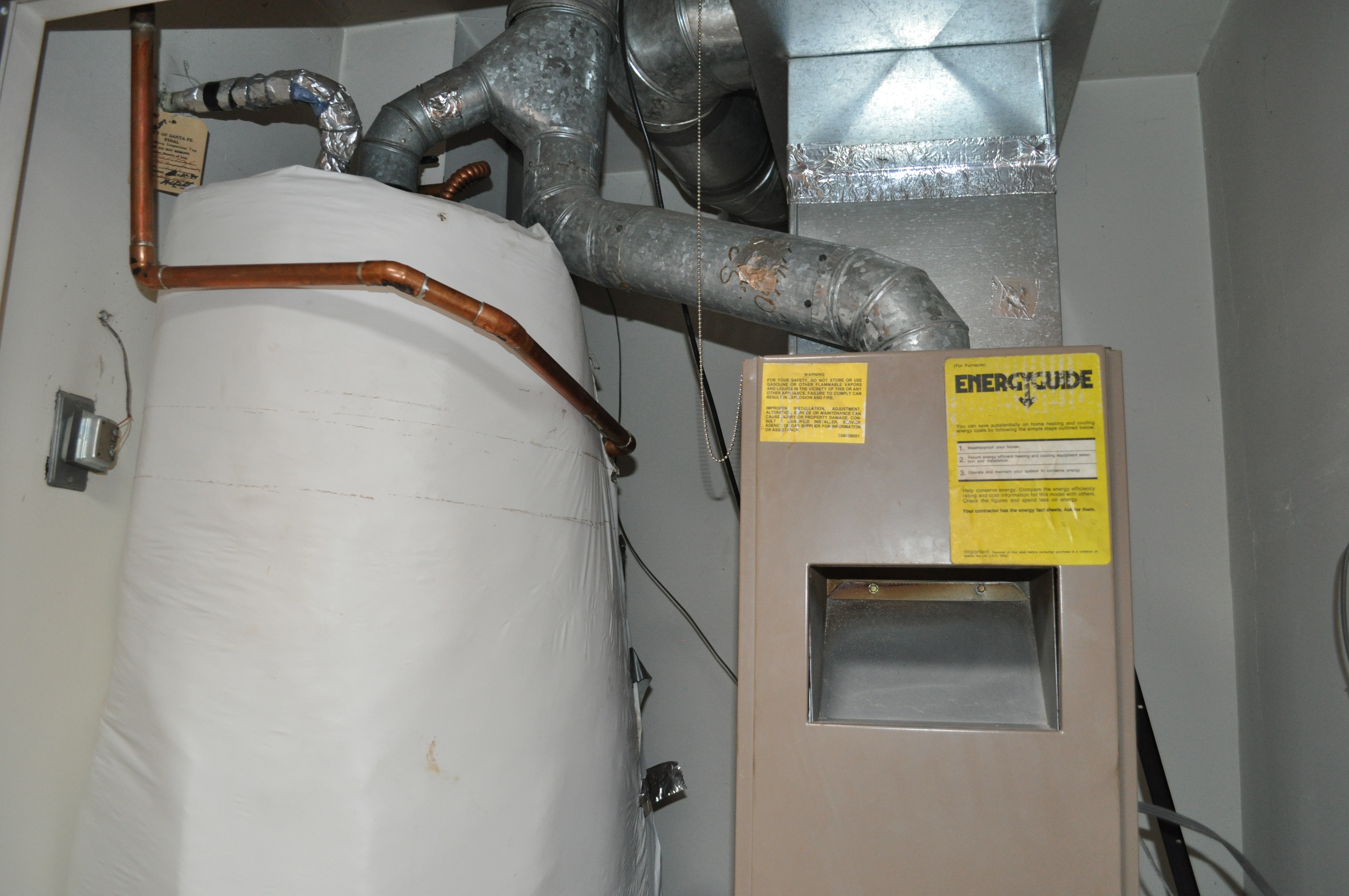
This utility room houses a high-efficiency gas boiler to provide hot water for the radiant floor heating system and faucets. It also has a central air source heat pump and an energy recovery ventilator.
Image

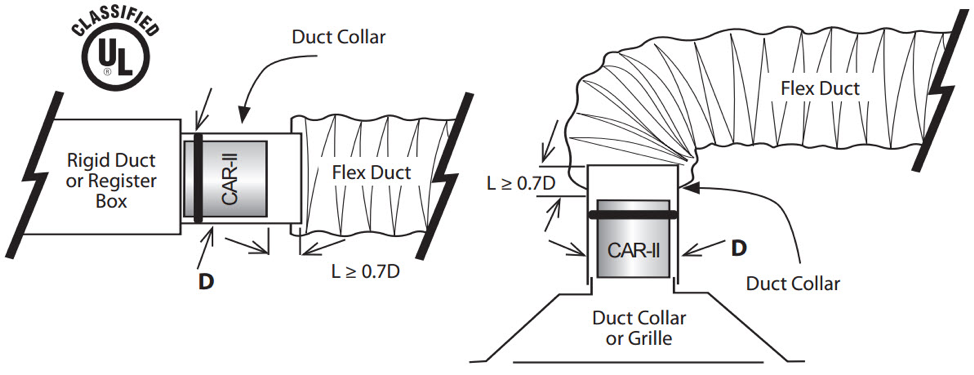
To attach the flex duct to a main trunk duct or any other connection, the flex duct is pulled over the connecting collar at least 2 inches past the raised bead, then the insulation is pulled back
Image
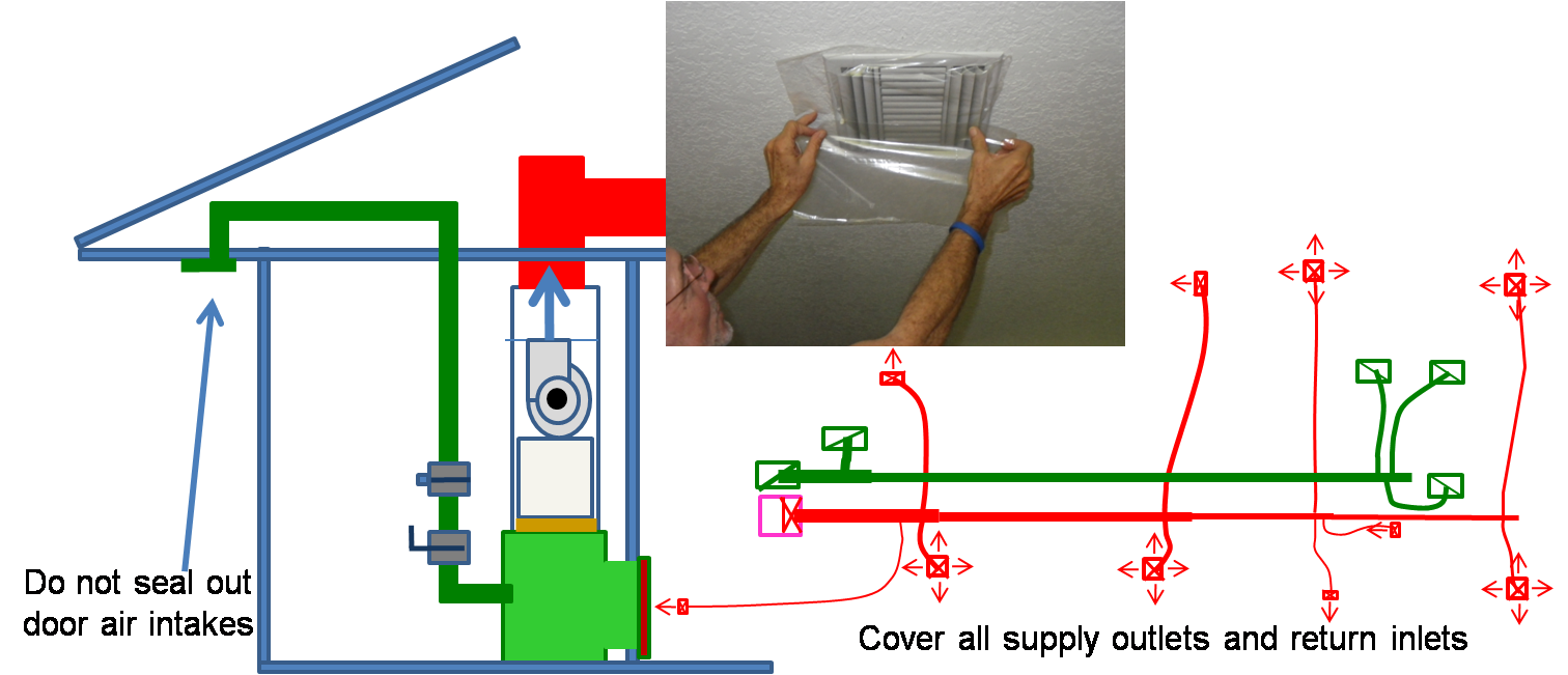
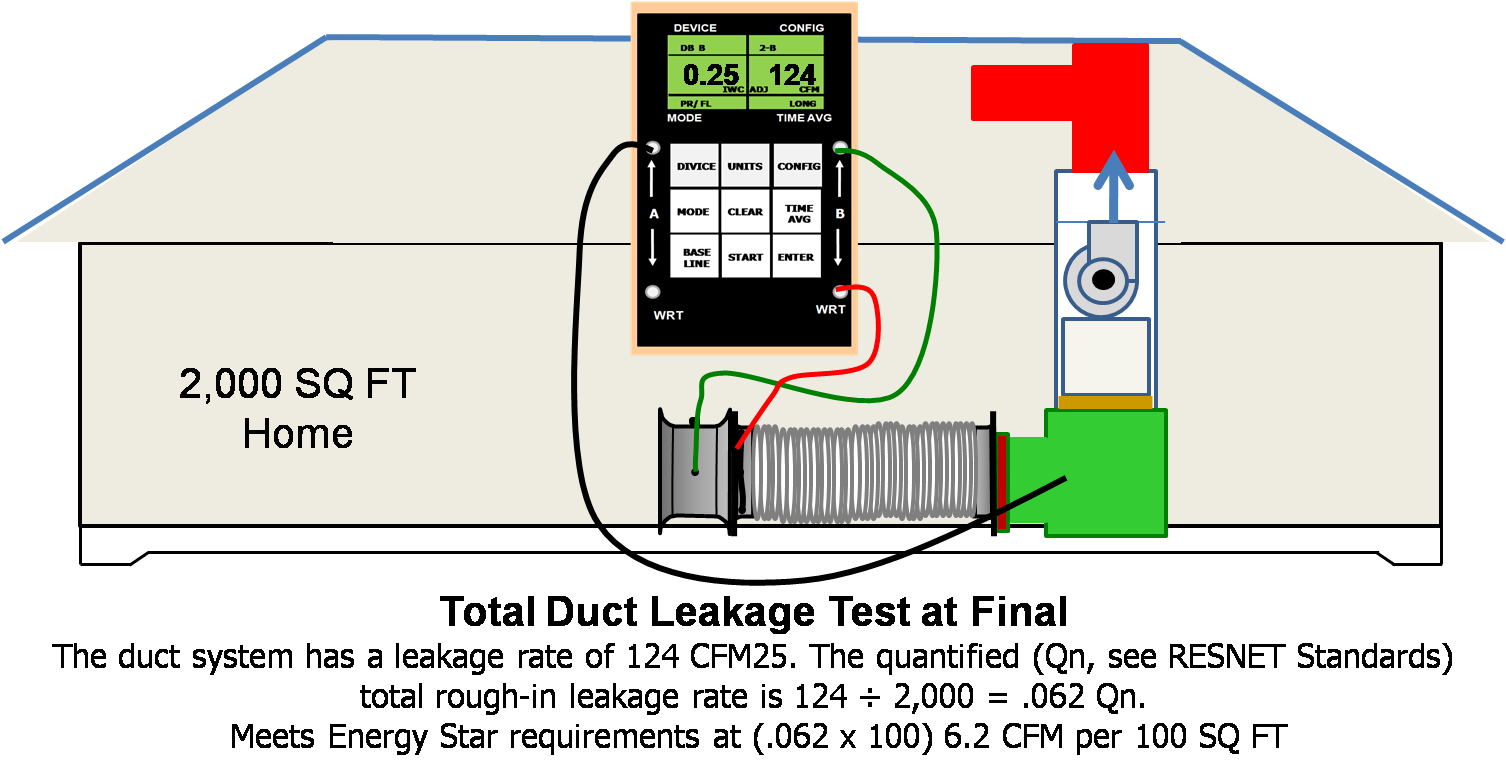
To prepare for a total duct test at final, cover all of the supply outlets and return inlets
Image
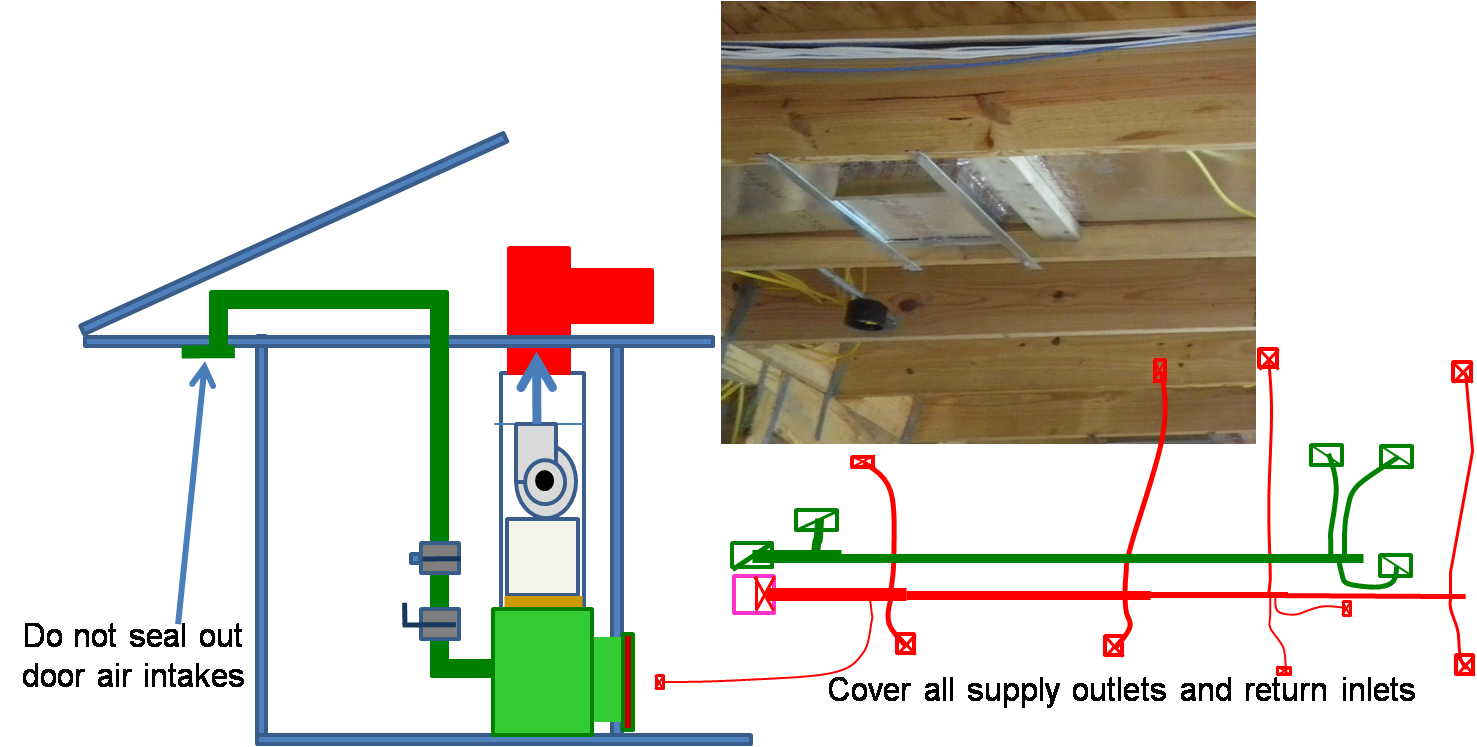
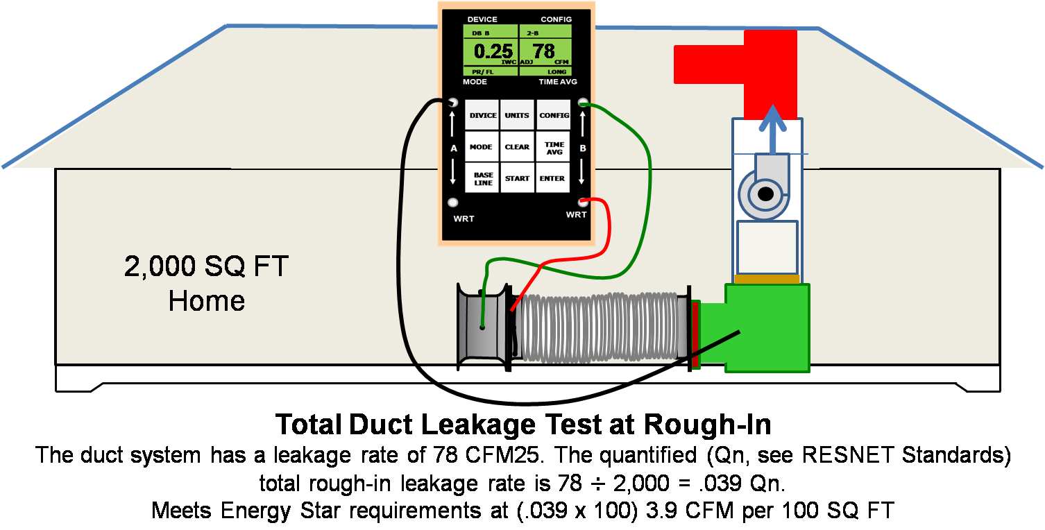
To prepare for a total duct test at rough-in, cover all of the supply outlets and return inlets
Image

Image
Image
Image
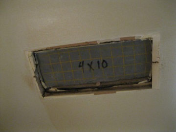
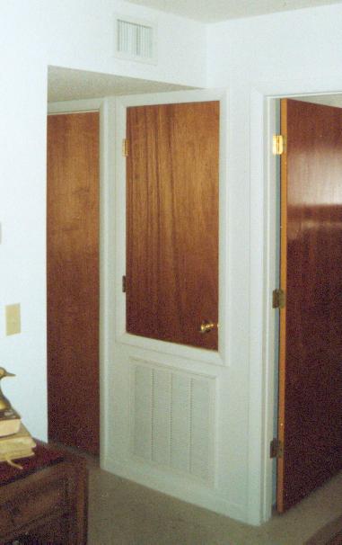
Transfer grills and jump ducts provide pathways for air to reach the centrally located HVAC return grille, even when bedroom doors are shut.
Image
Image
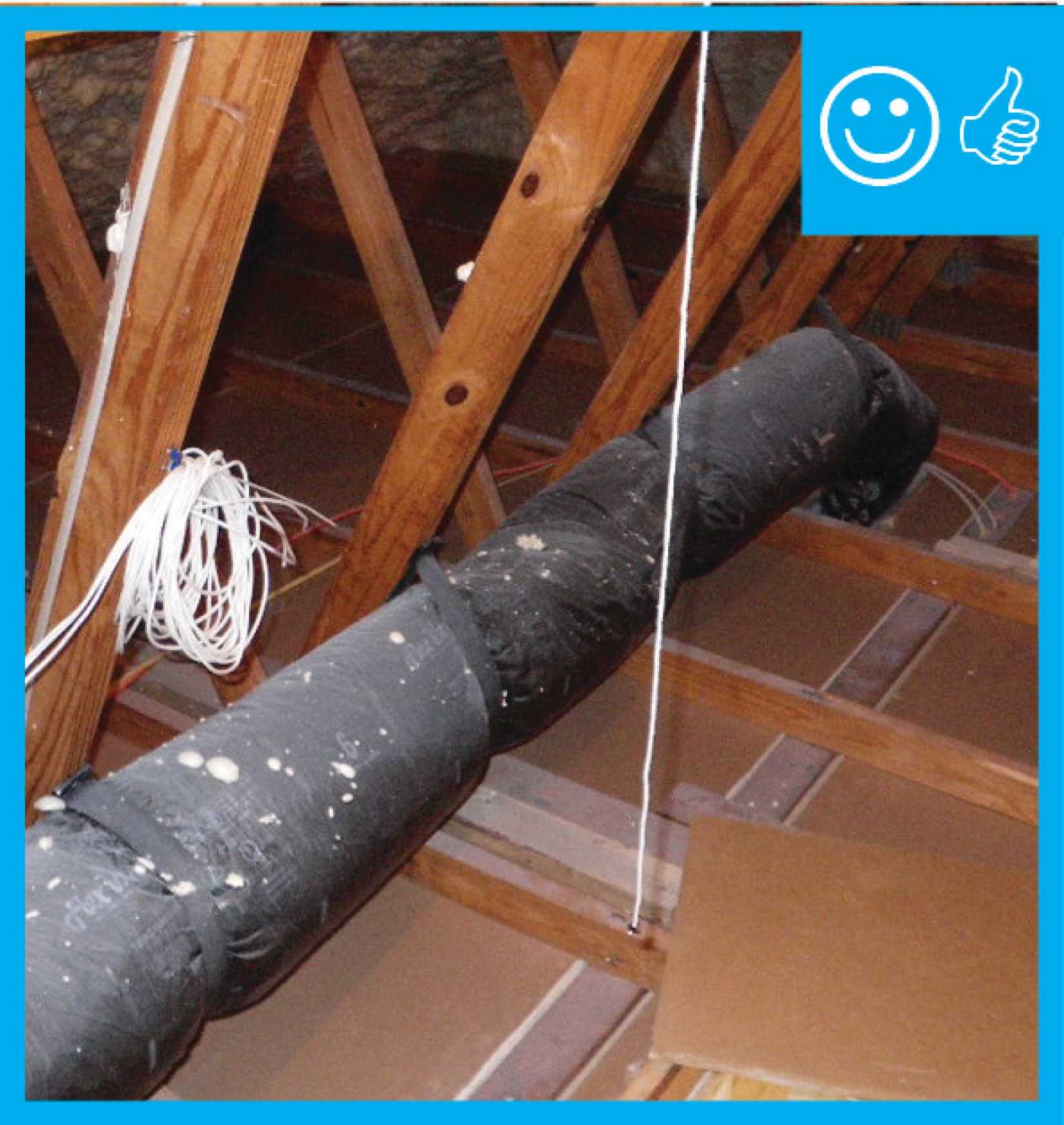
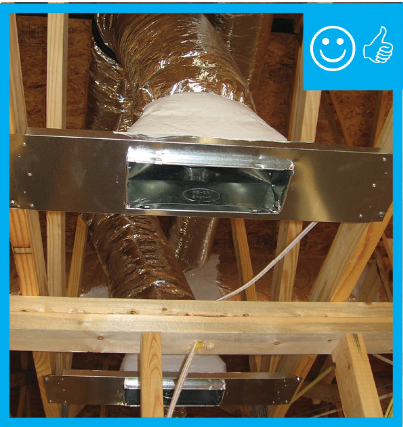
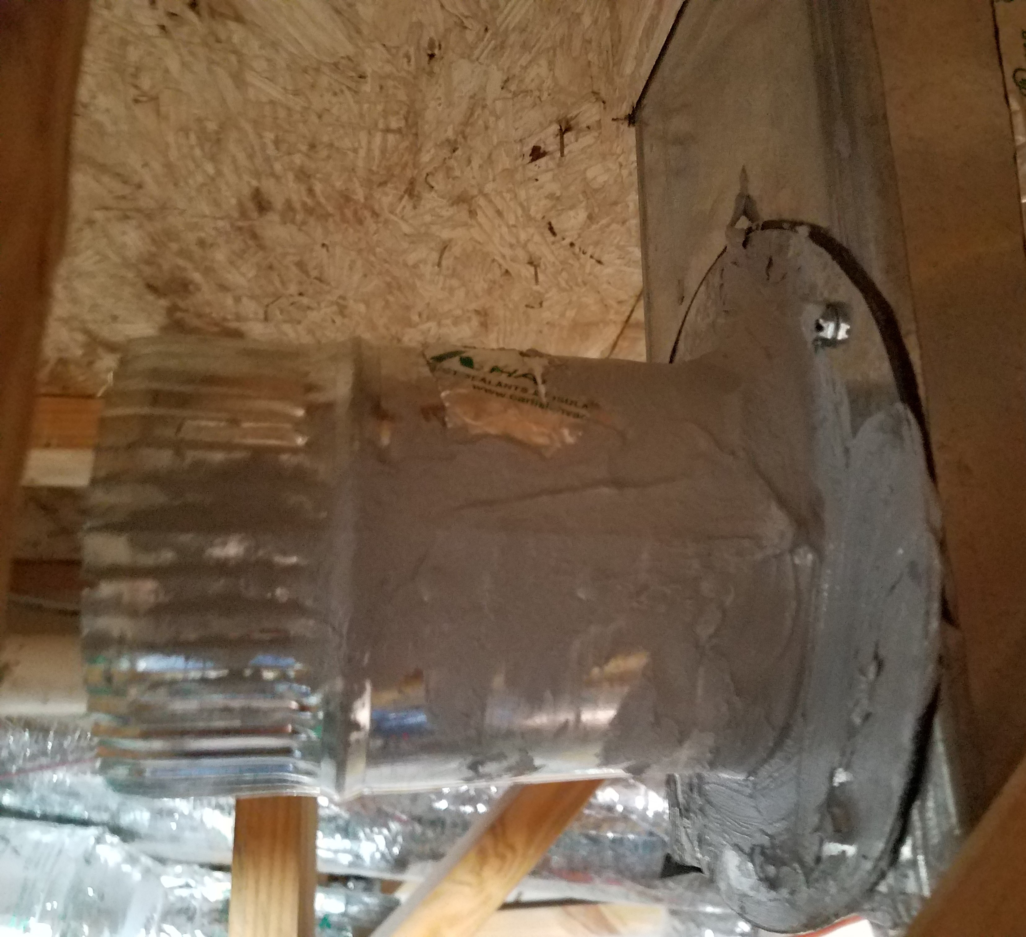
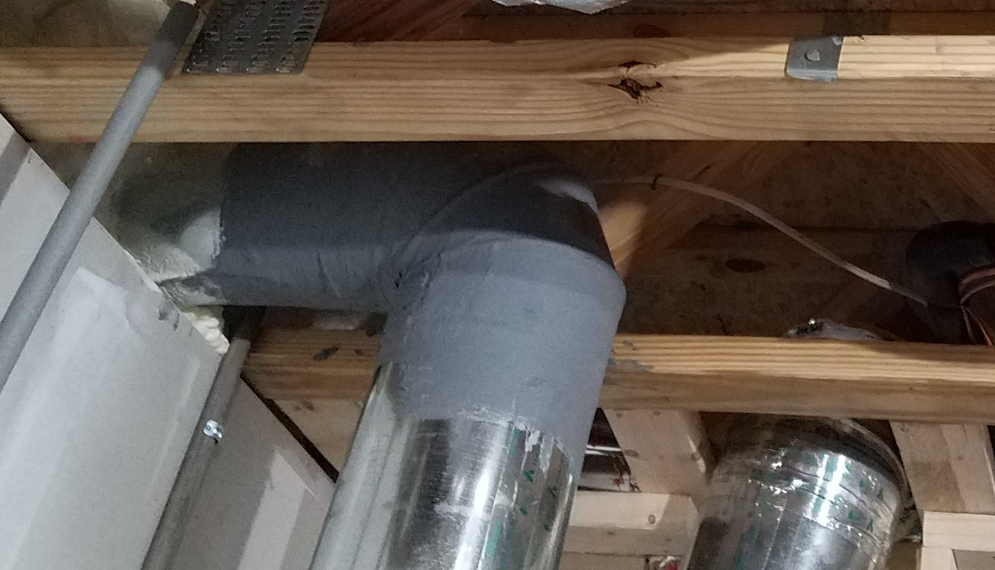
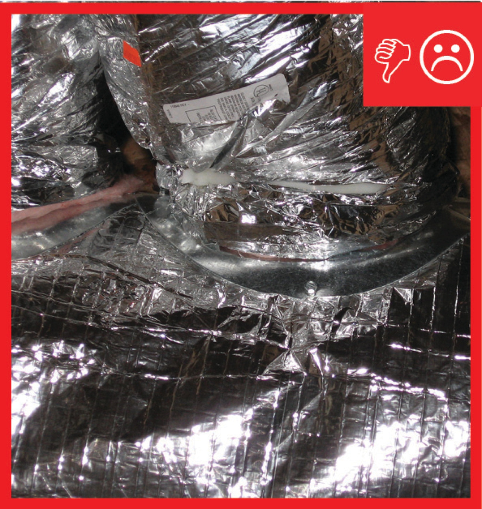
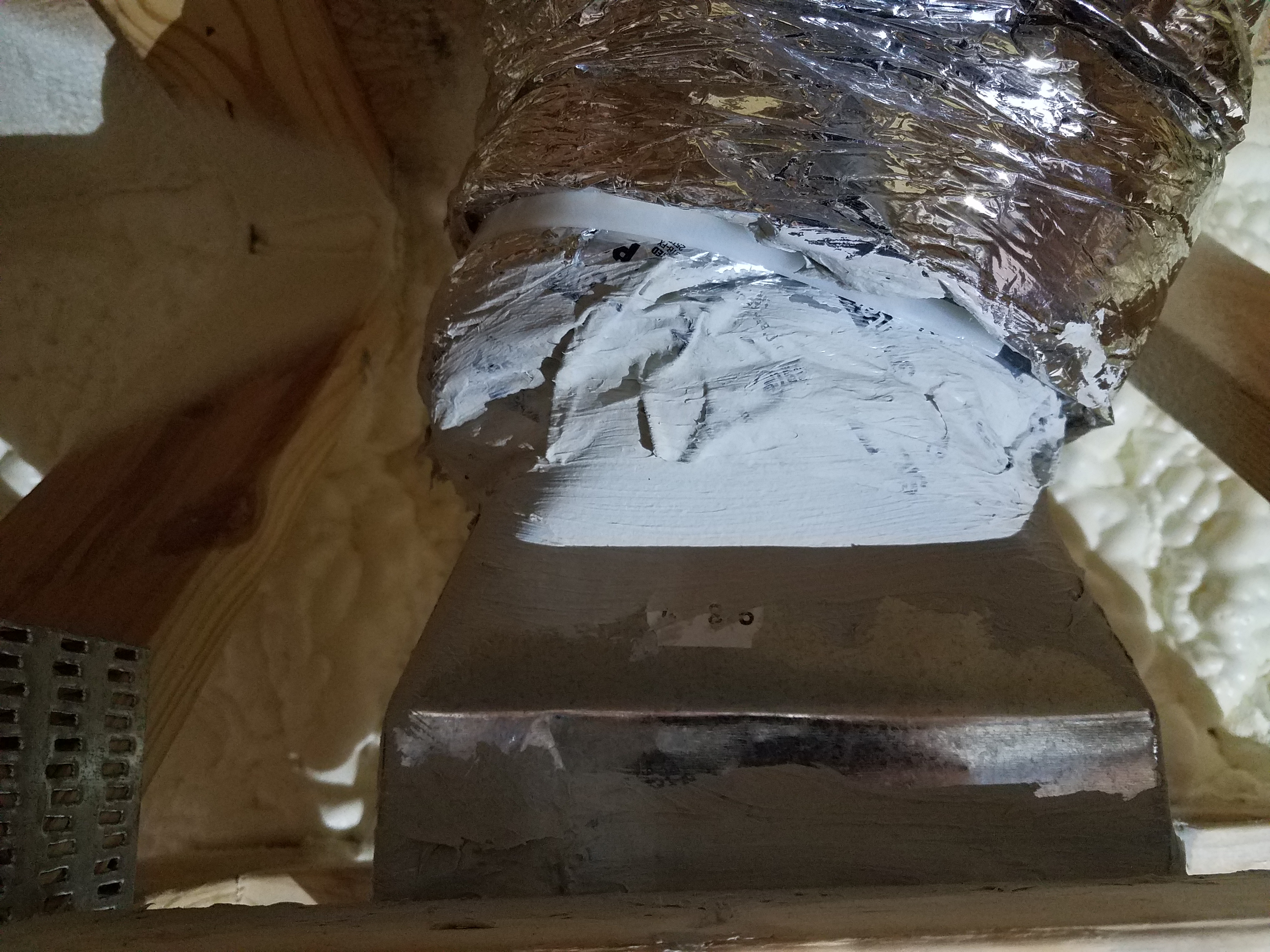
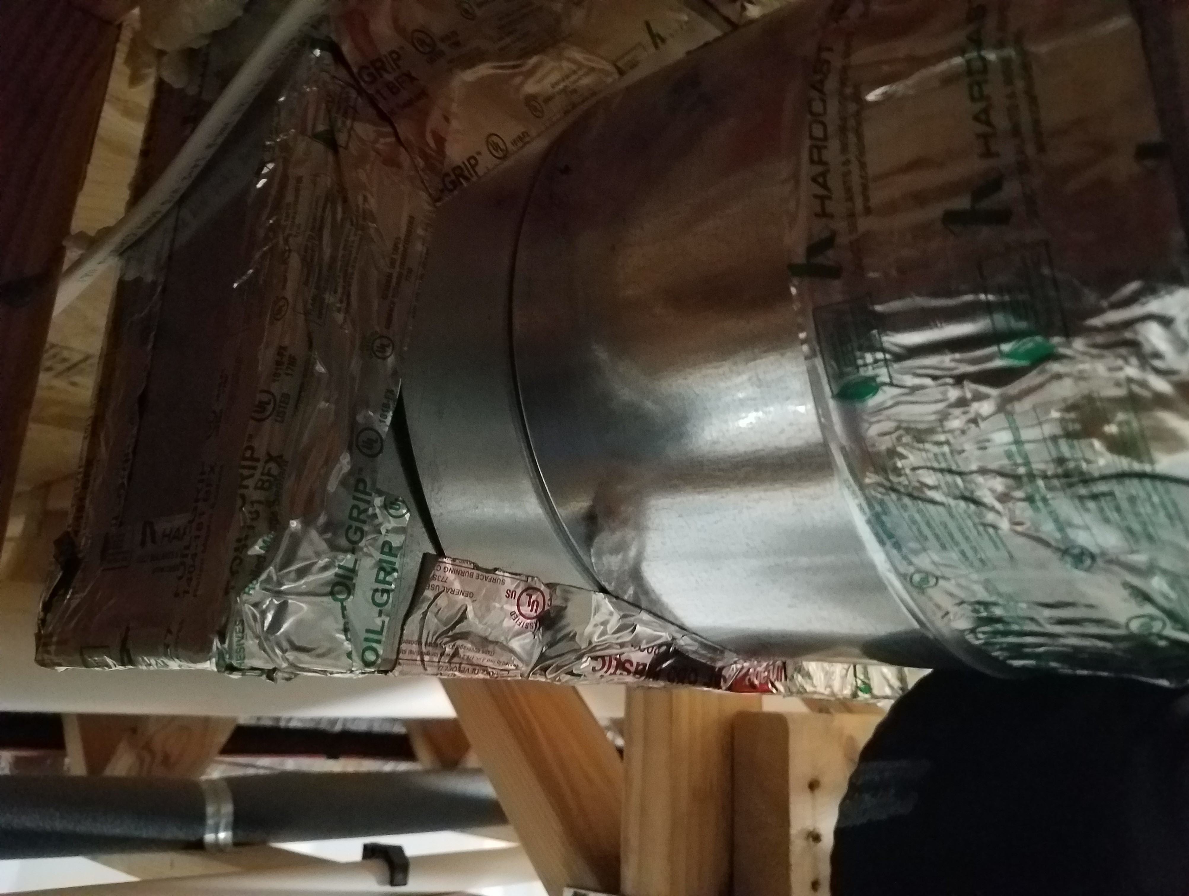
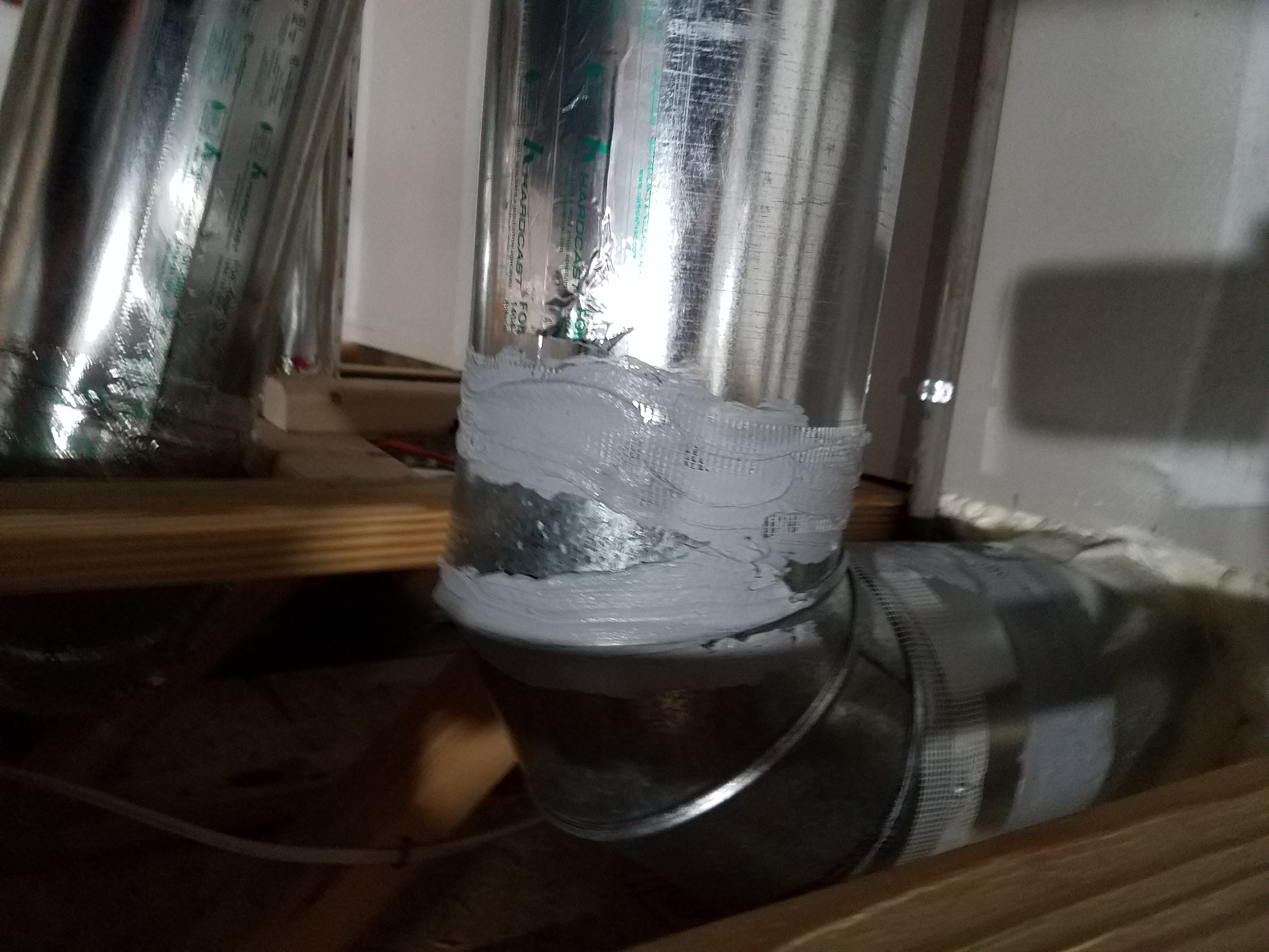
Trunk to duct connections are properly insulated and have been sealed with mastic
Image
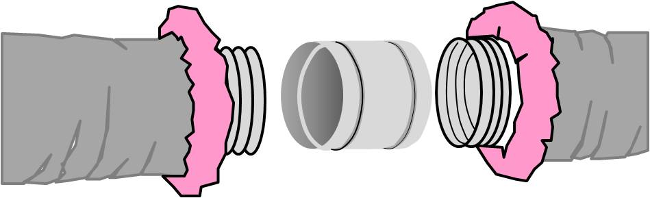
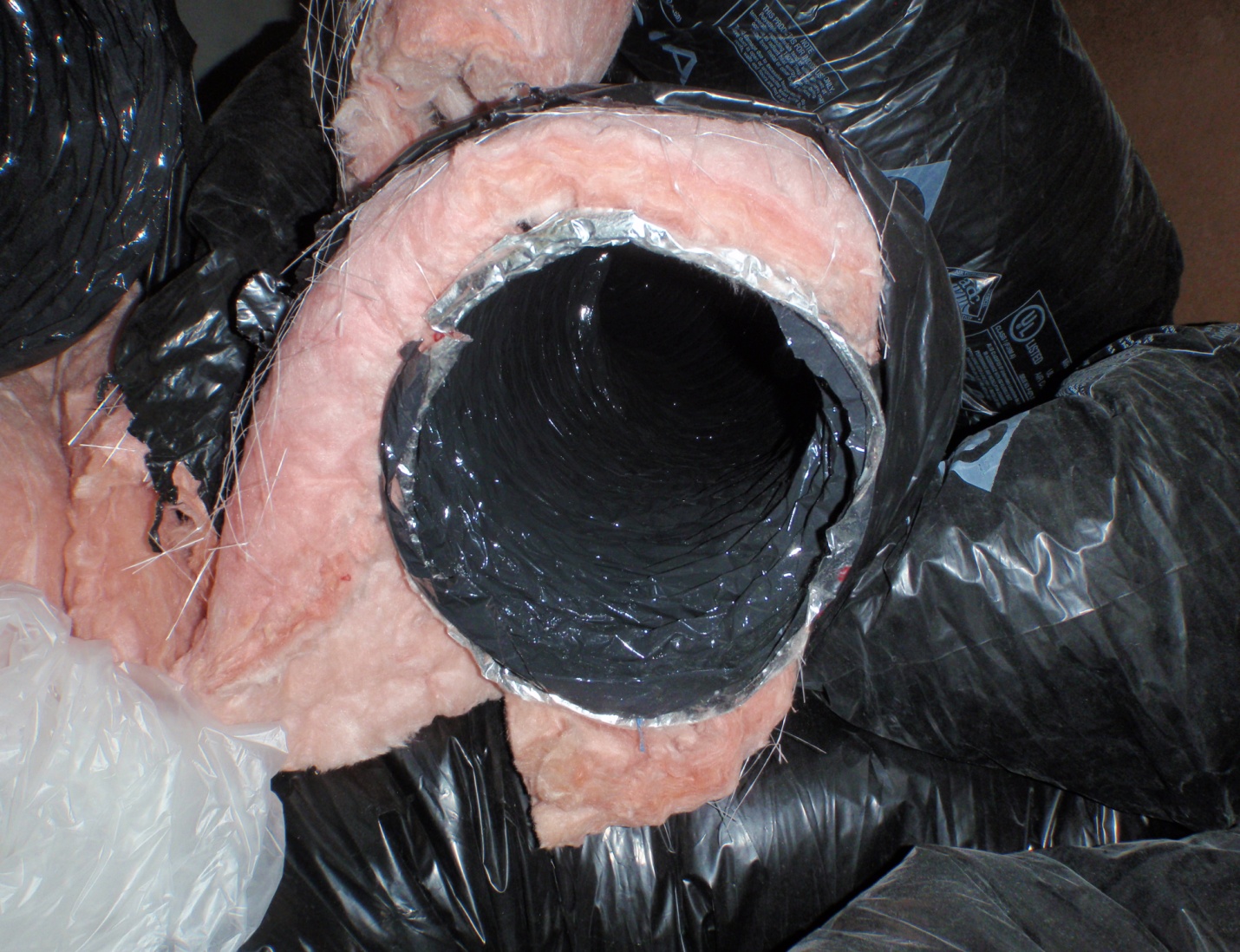
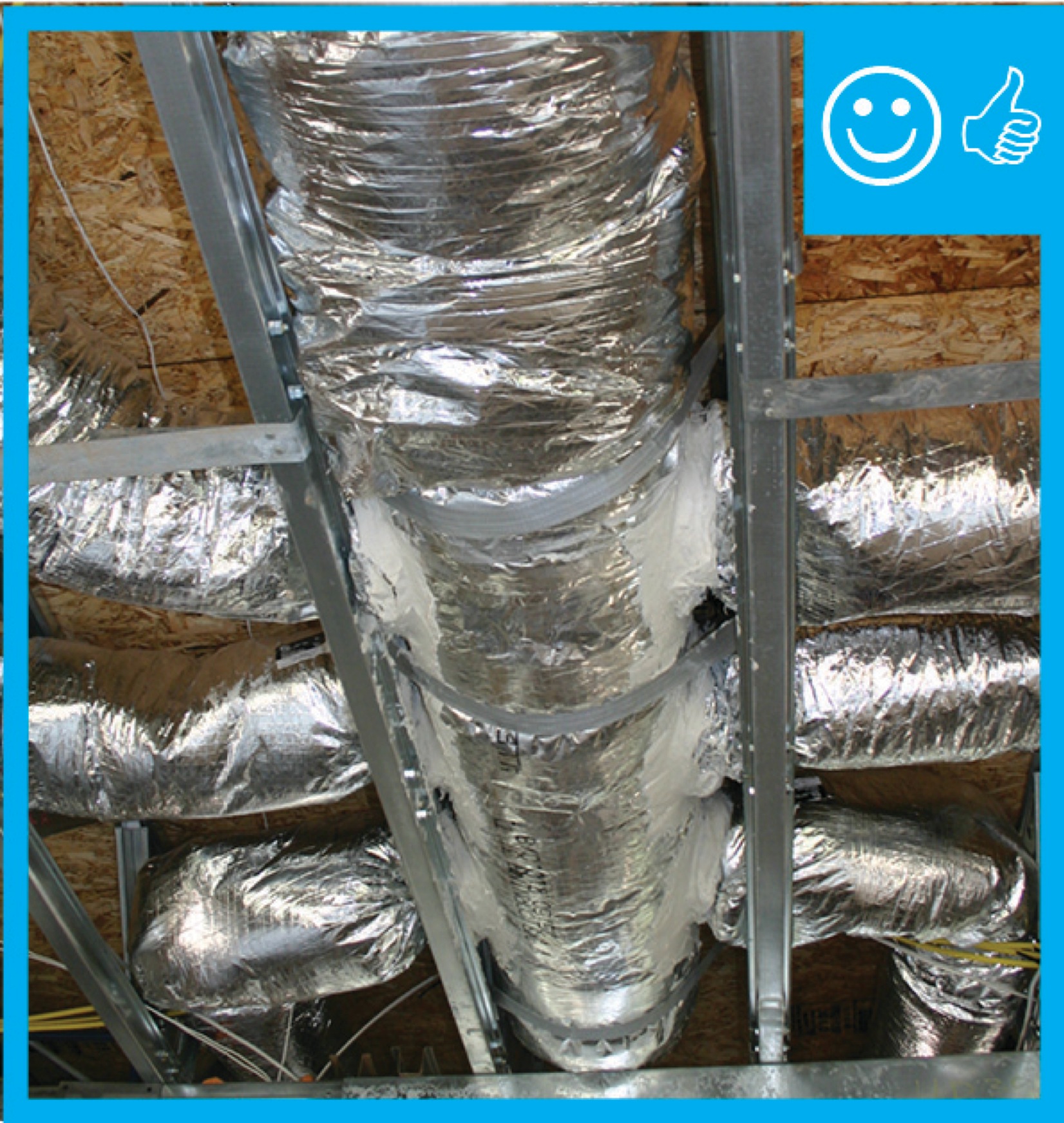
Two pieces of flex duct are spliced together with a metal sleeve, nylon draw bands, mastic, metal tape, and more mastic
Image

Image
Image
Image
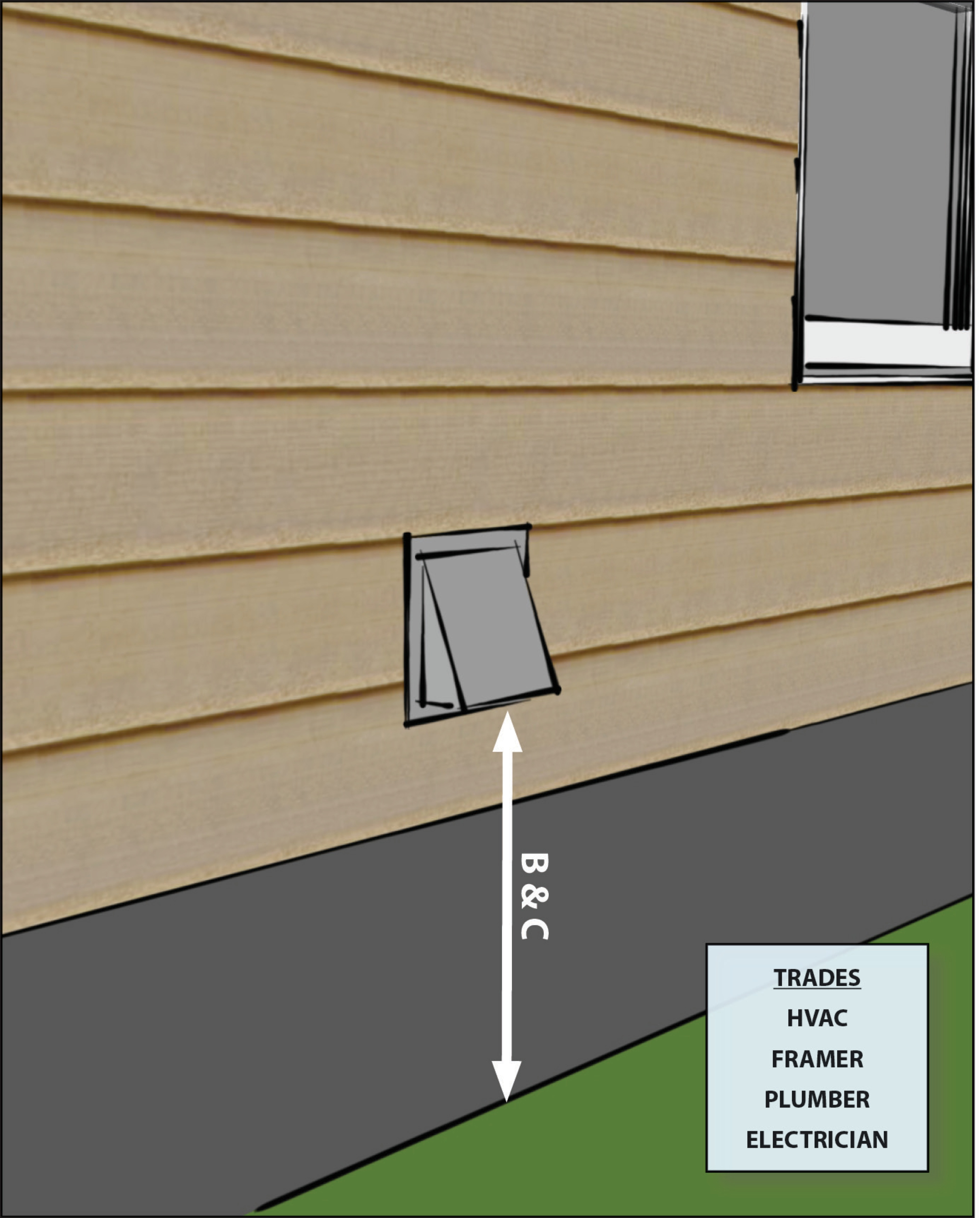
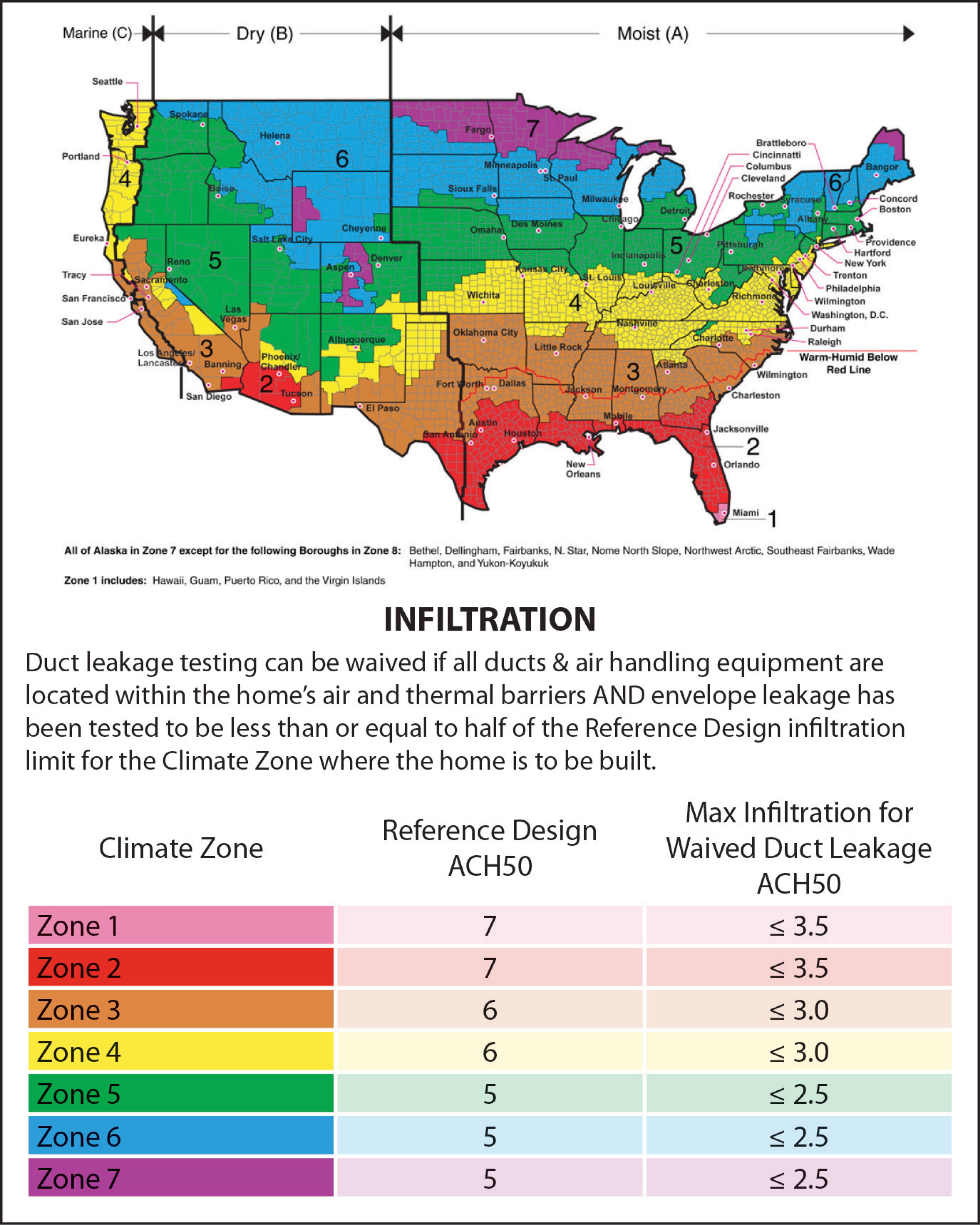
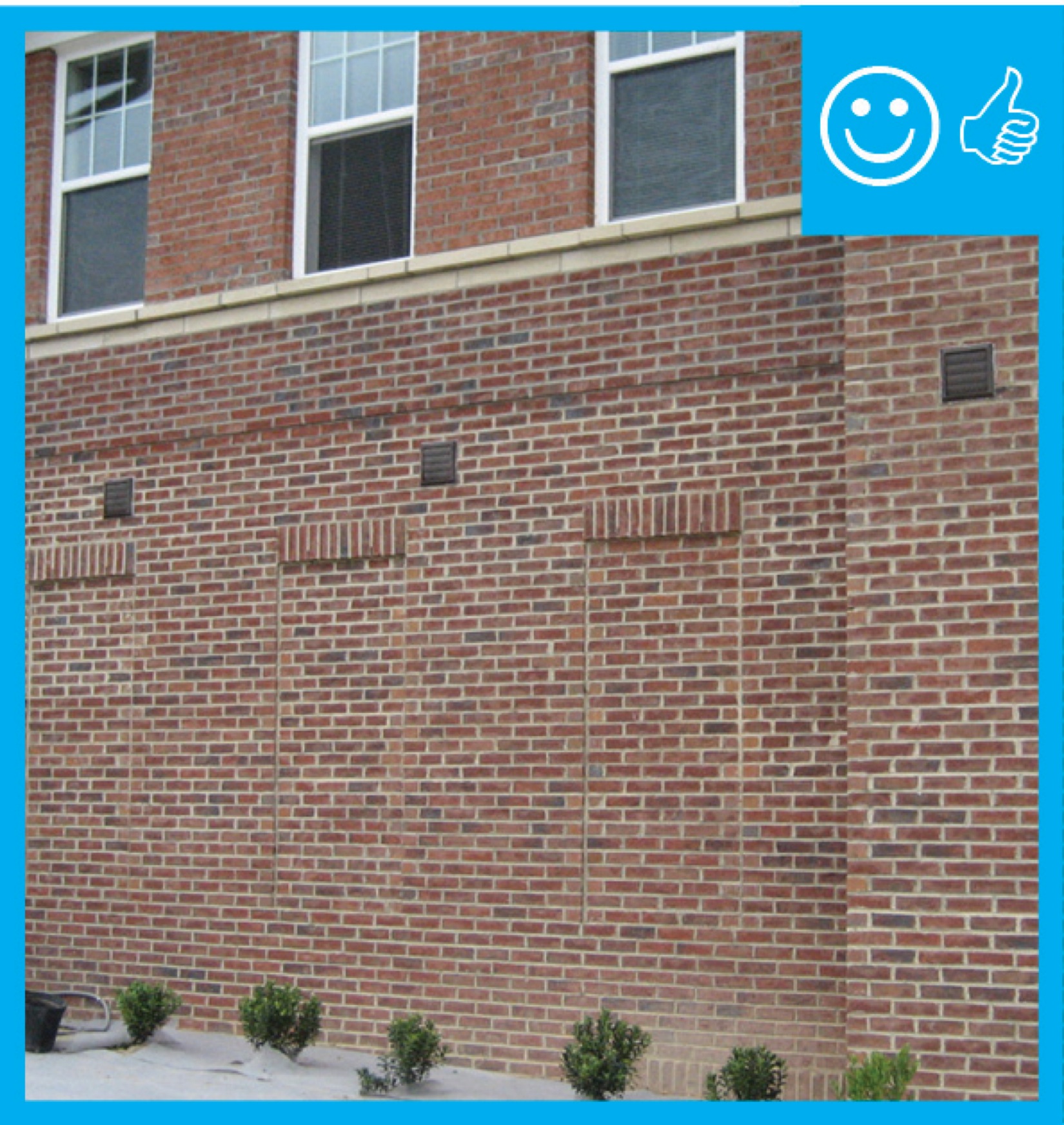
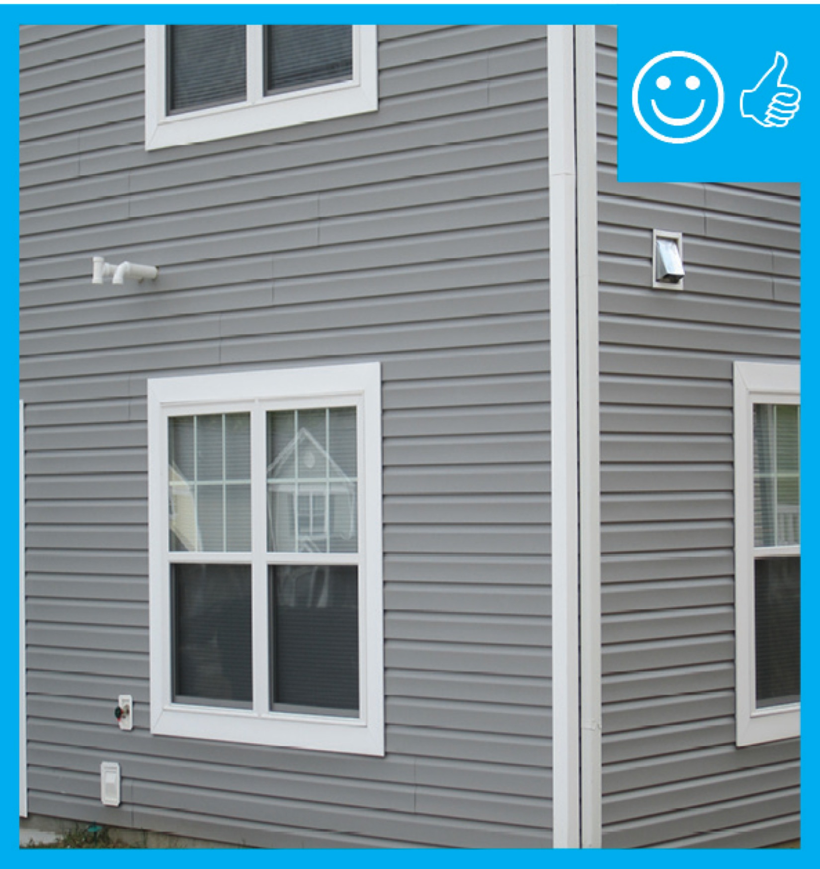
Ventilation air inlets ≥ 2 ft. above grade or roof deck in Climate Zones 1-3 or ≥ 4 ft. above grade or roof deck in Climate Zones 4-8 and not obstructed
Image
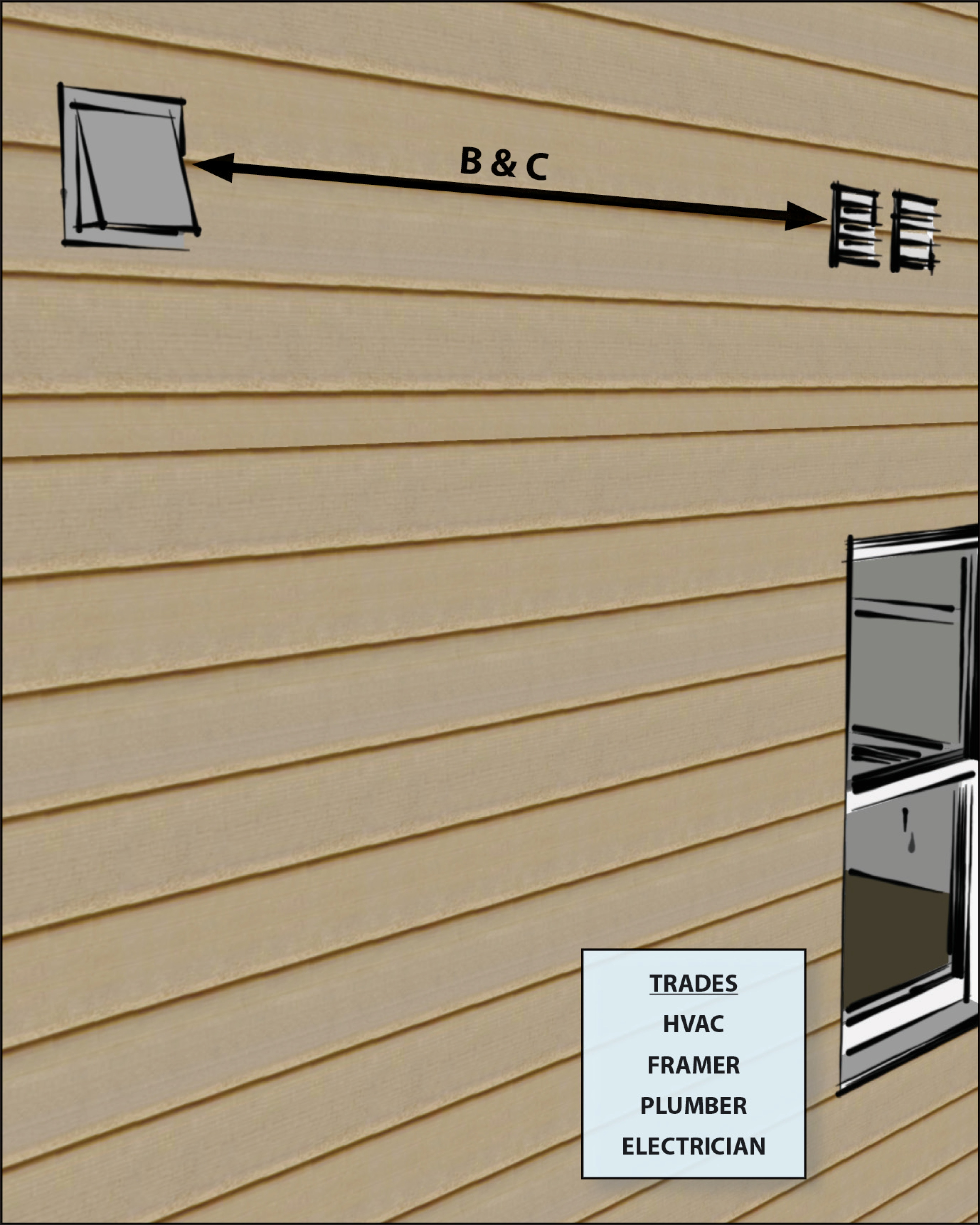
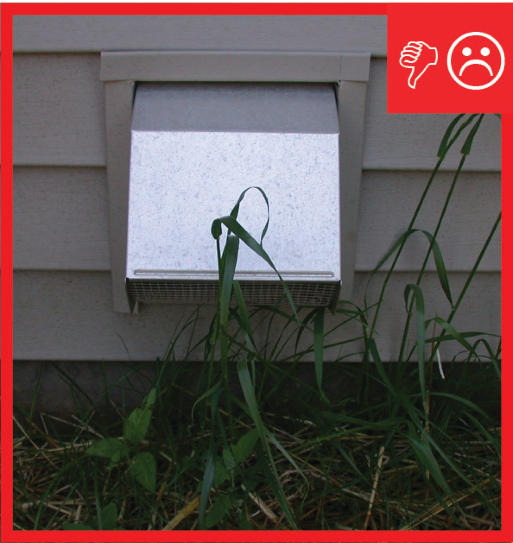
Ventilation air inlets located ≥10 ft. of stretched-string distance from known contamination sources such as stack, vent, exhaust hood, or vehicle exhaust
Image

Image
Image
Image
Image
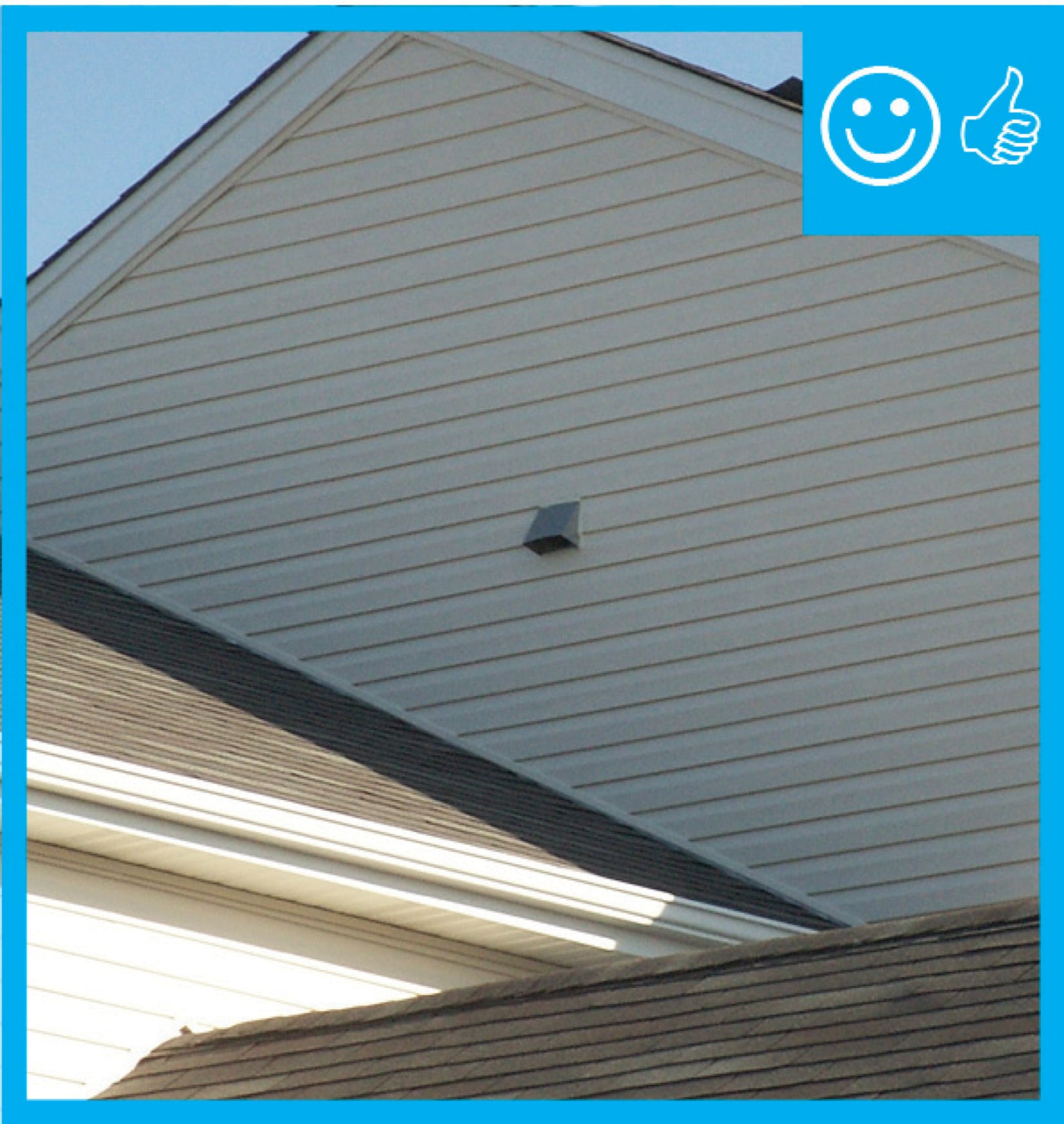
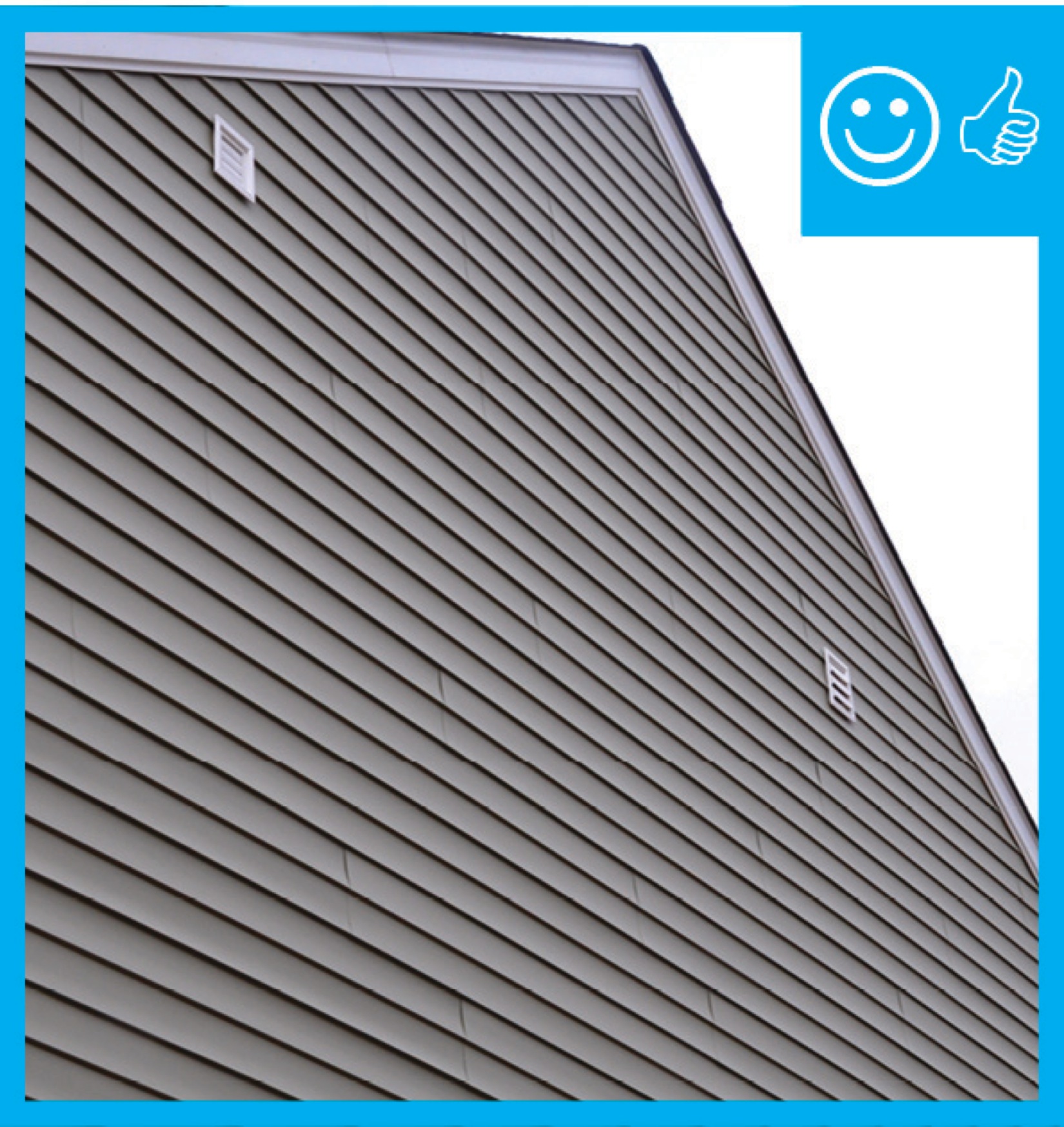
Ventilation inlet is not near any exhaust outlets/contamination sources and is at least 2 ft. above the roof deck
Image
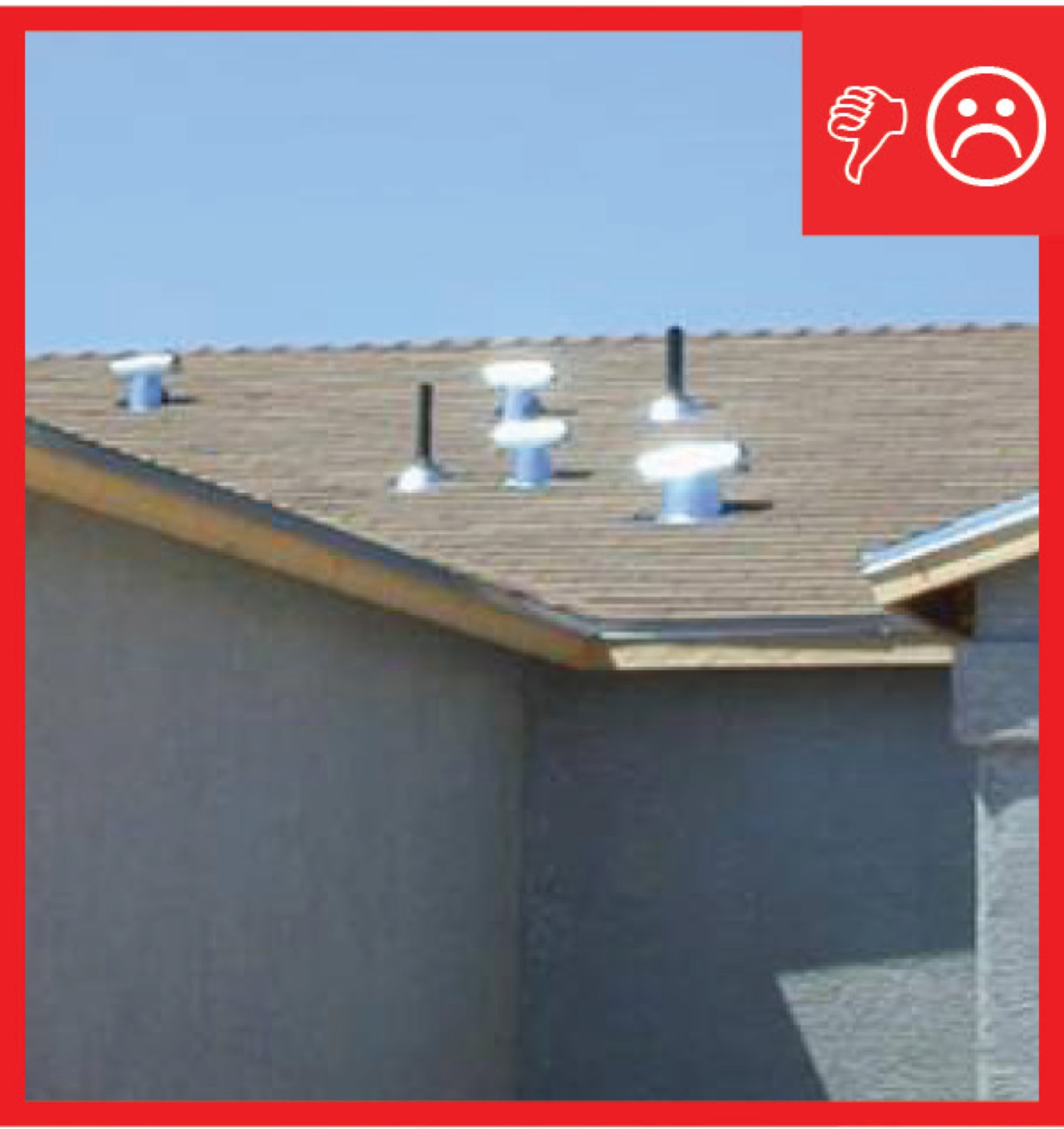
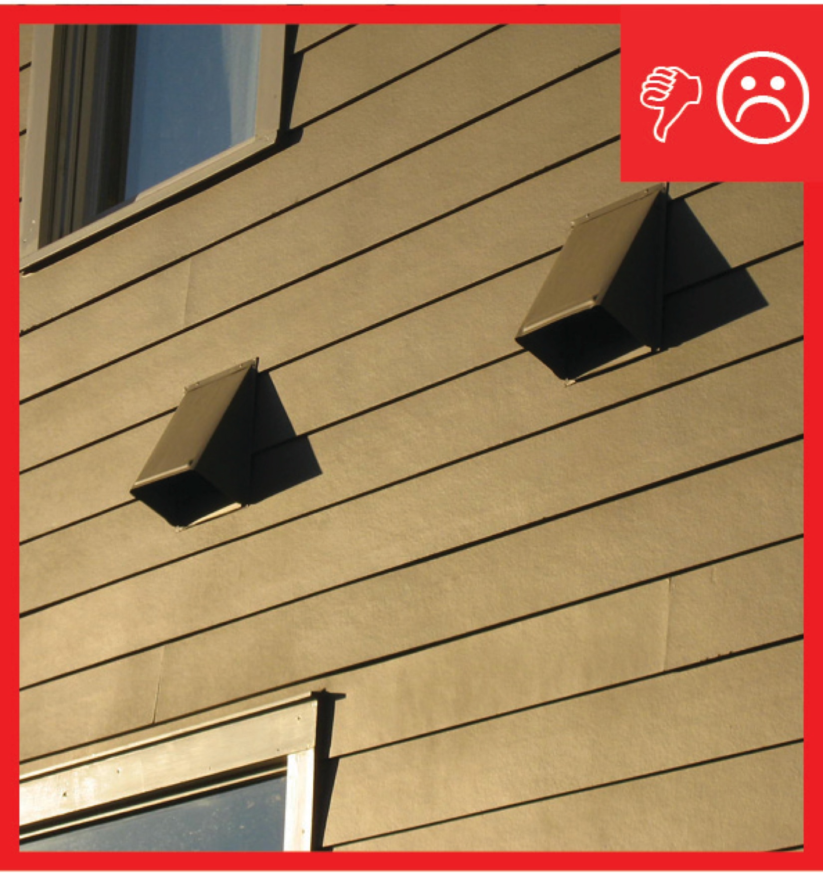
Ventilation inlet is too close to exhaust outlets and does not extend at least 2 ft. above the roof deck
Image
Image
When wrapping metal ducts with insulation allow two inches of overlap and staple along the seam with outward clinching staples
Image
Wide saddle support provides sturdy support for the turn without pinching the flex duct
Image
Image
Image
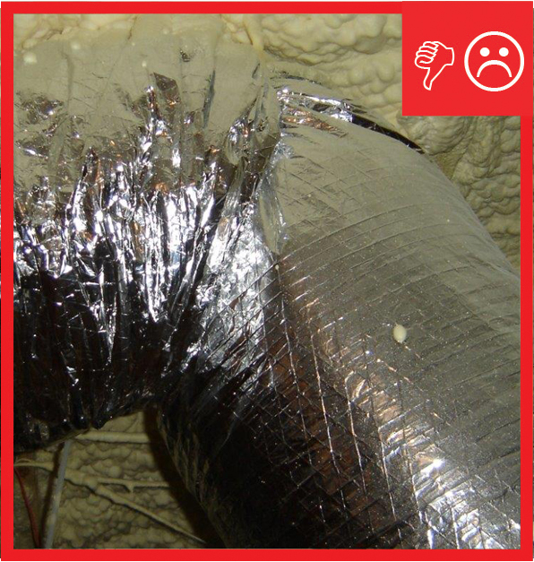
Wrong - Duct seams were sealed with regular duct tape which has failed to hold; seams should have been sealed with mastic or approved metal tape.
Image
Image
Wrong - Flex duct insulation is overly compressed in 3 ways; Zip-tie fastener is over the insualtion not under the insulation at the duct boot collar, duct turning radius is too tight, and support strap is too tight.
Image
Image
Image
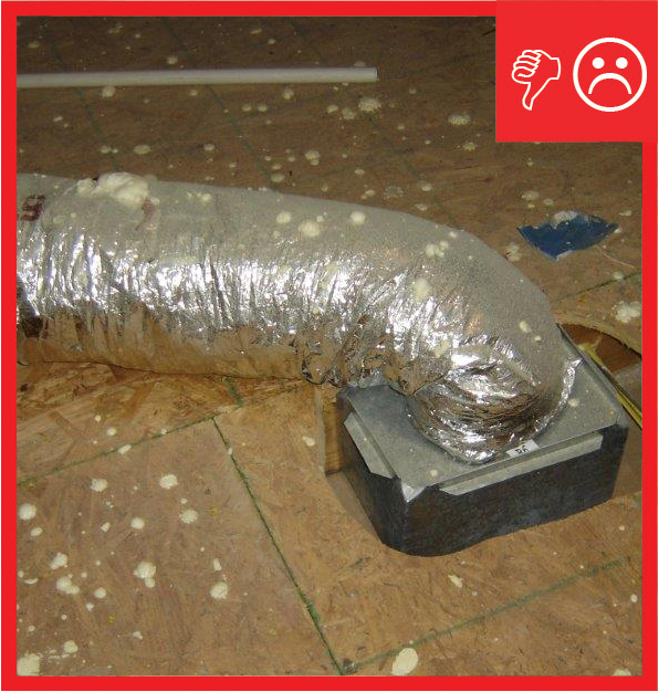
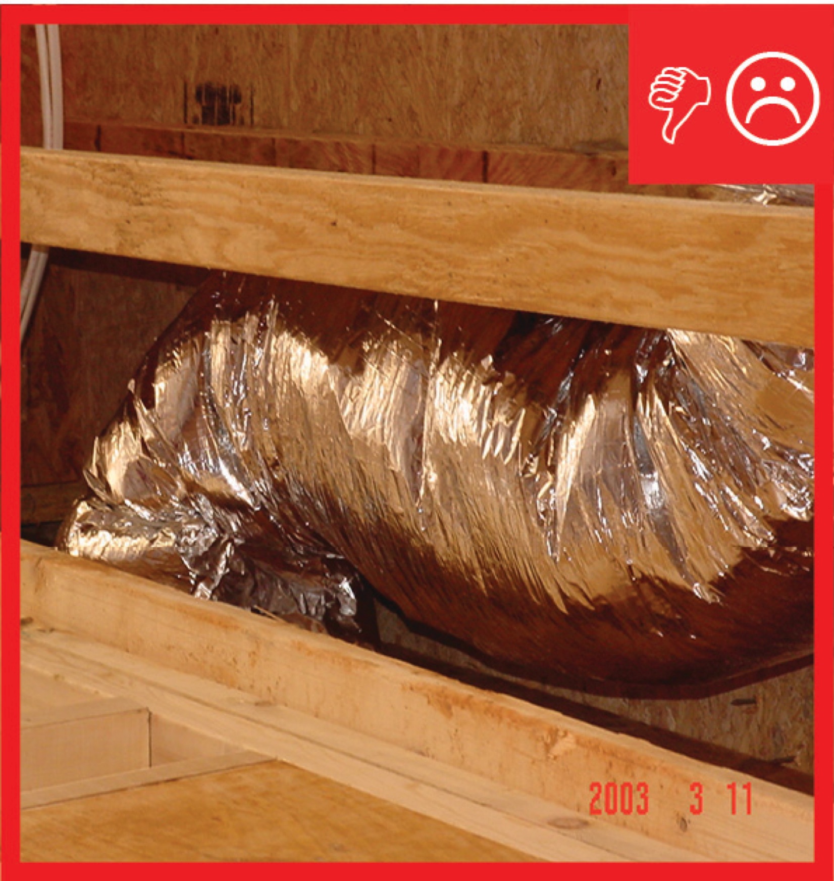
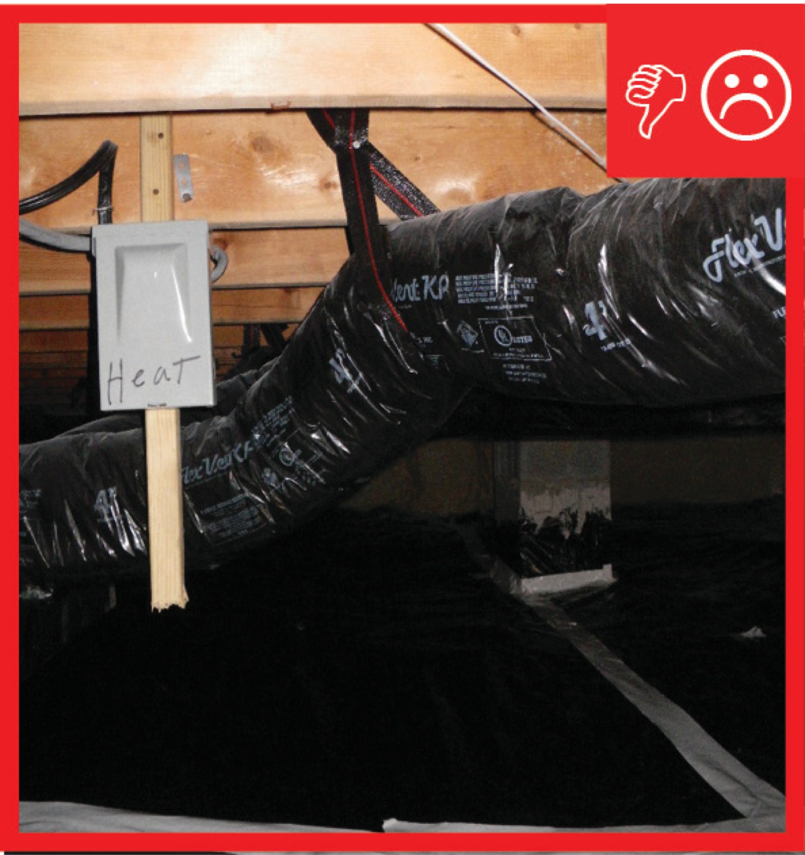
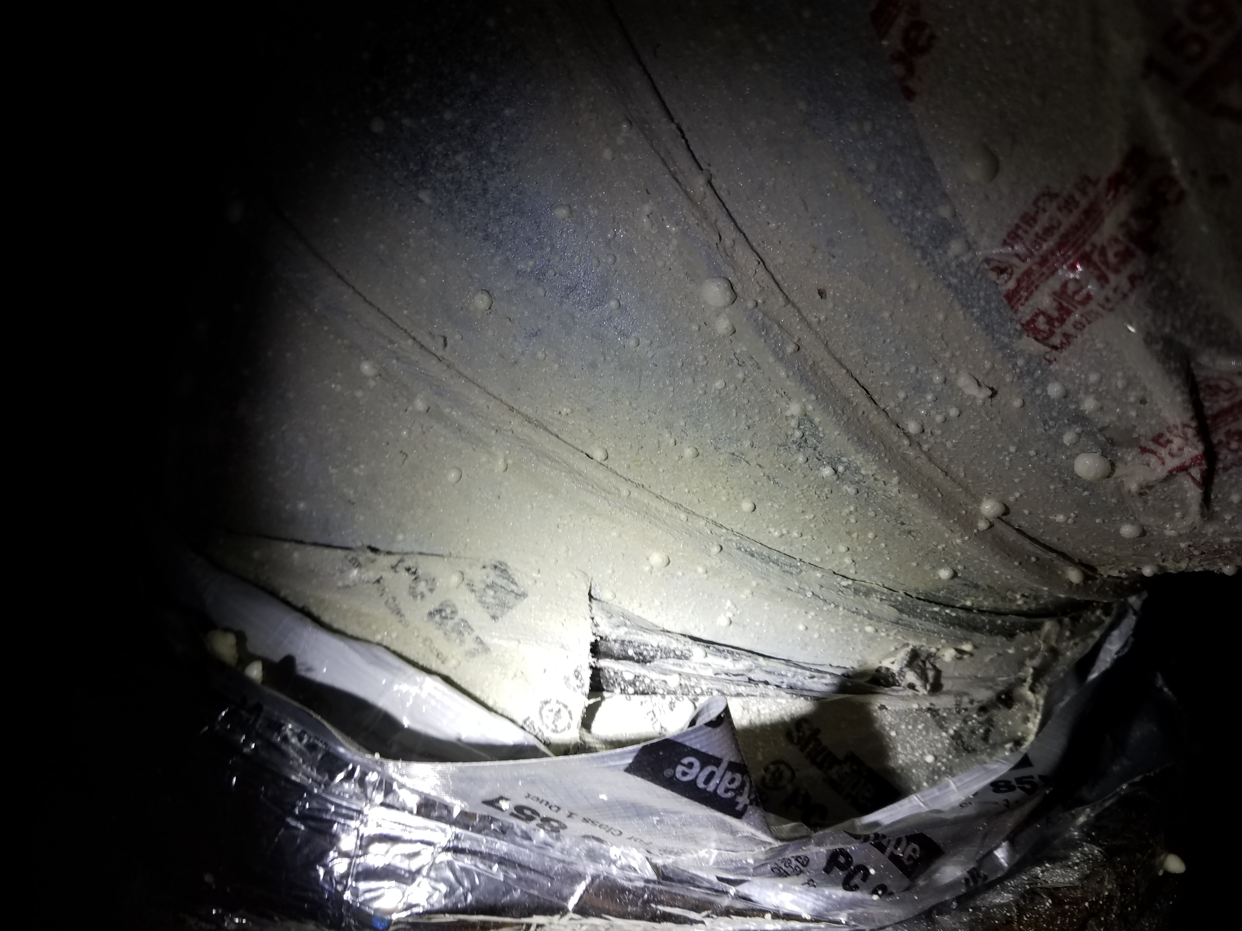
Wrong - Flex duct resting on floor compressing insulation and causing condensation
Image
Image
Image
Image
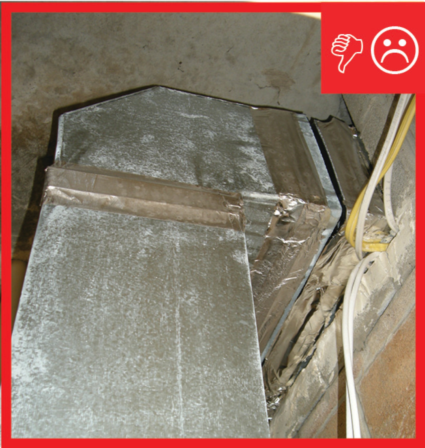
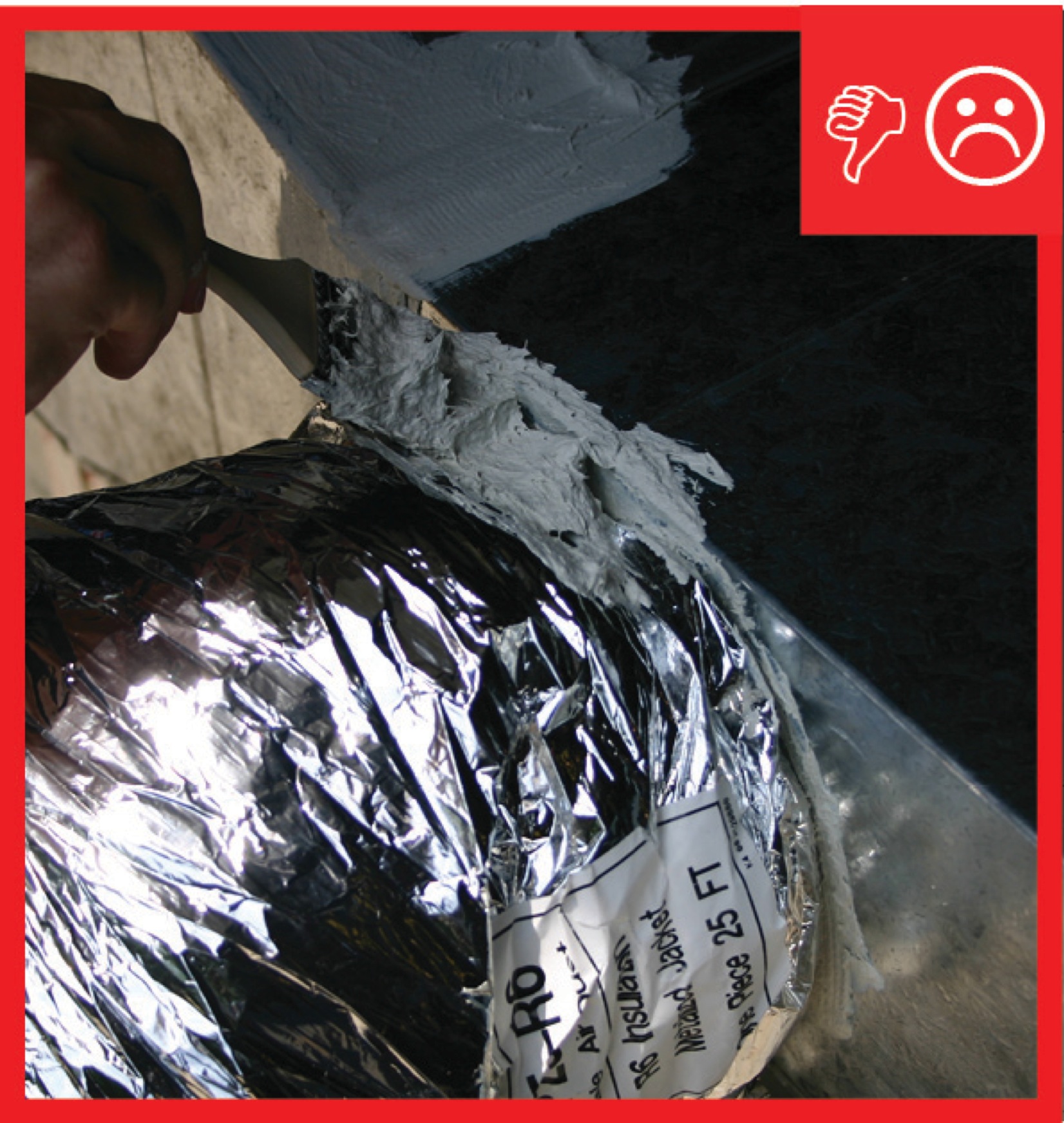
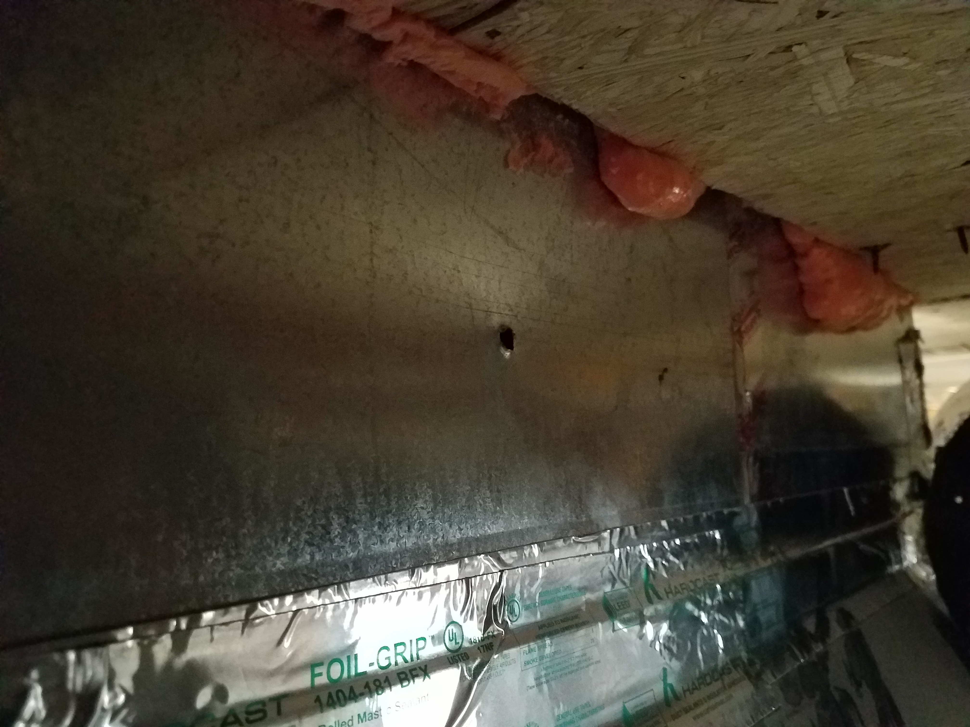
Wrong - Metal tape is poorly adhered and metal duct and duct-to-subfloor seam is not sealed.
Image

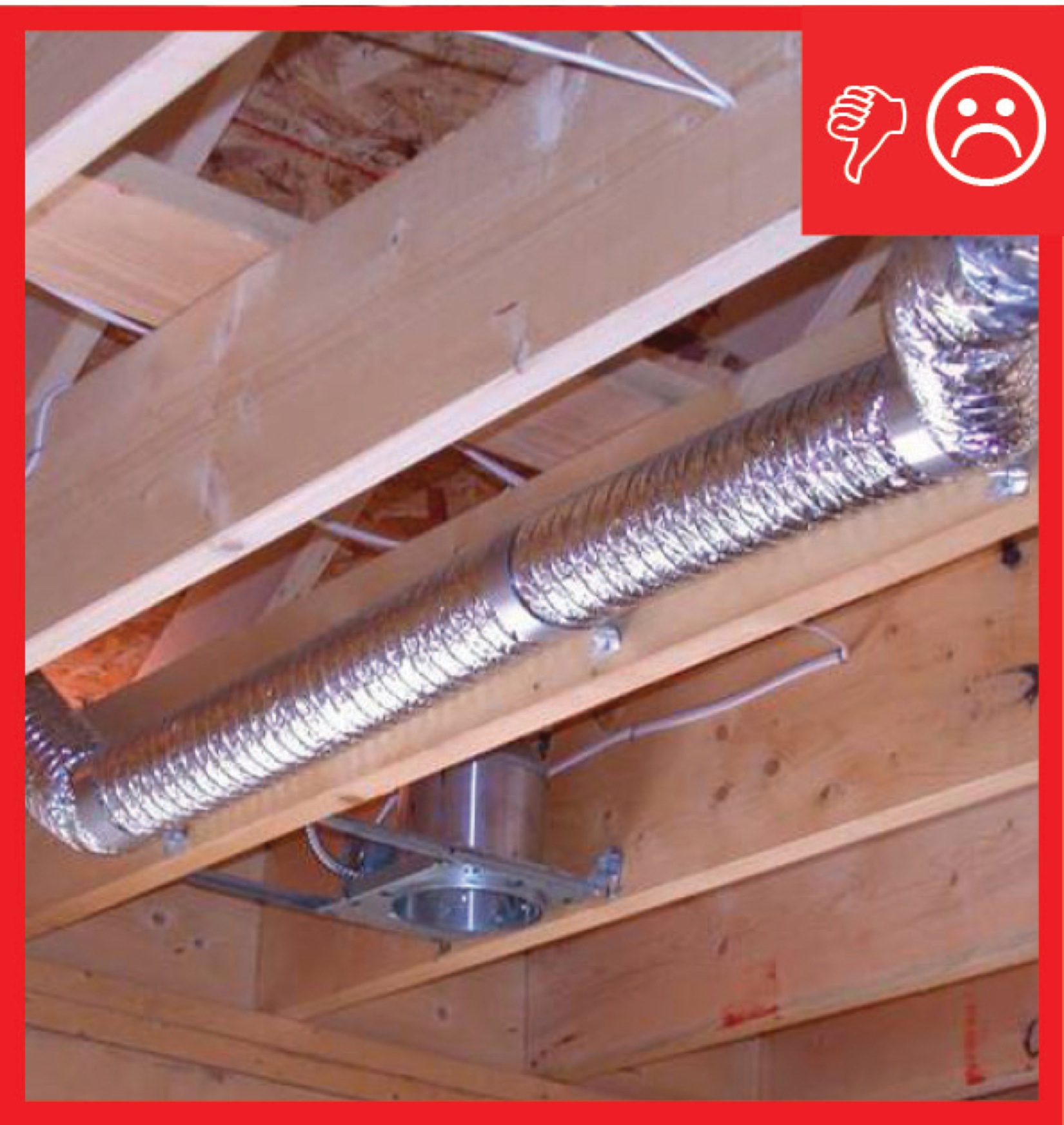
Wrong - Not enough straps were used to hang this flex duct so it is sagging, restricting air flow
Image
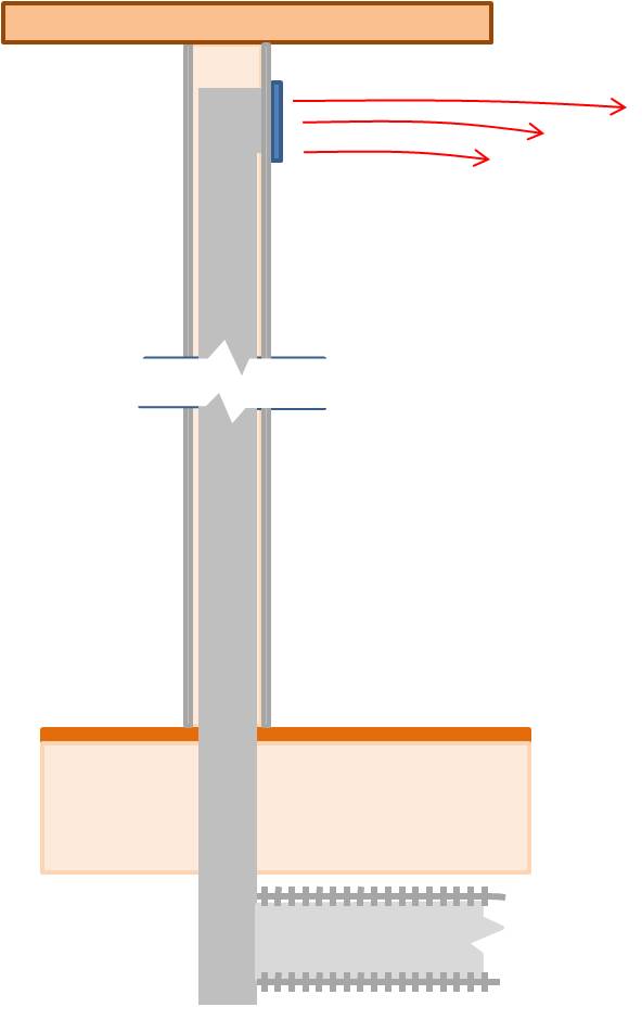
Wrong - Penetrations in walls for ducts should be air sealed to reduce air leakage.
Image
Image
Image
Image
Image
Image
Image
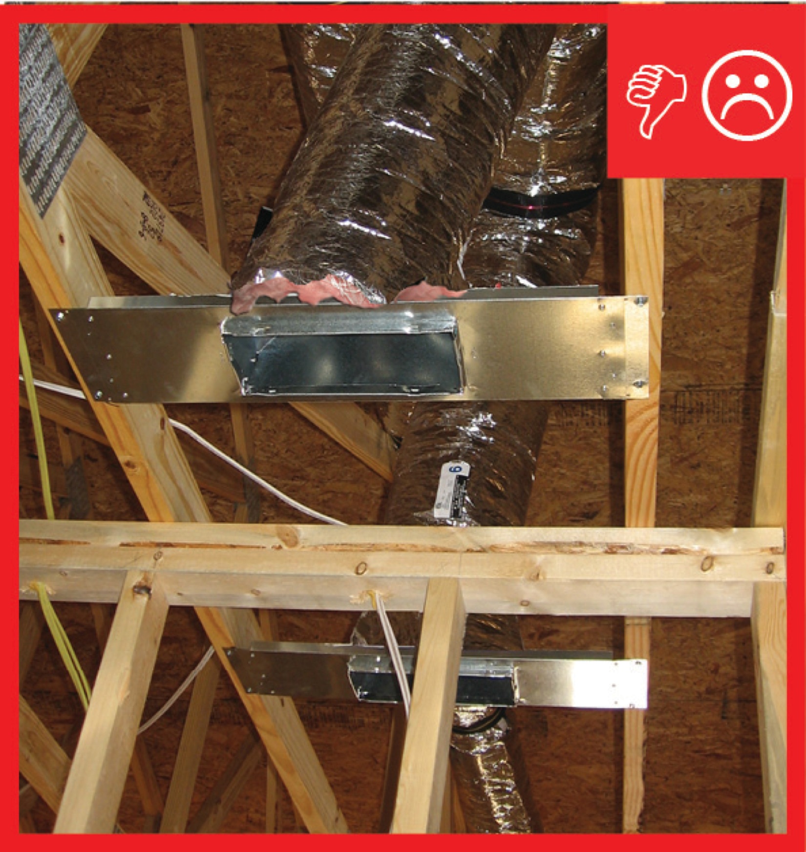
Wrong - The seam around the duct boot where the duct boot enters the trunk duct has not been completely sealed with mesh tape and mastic.
Image
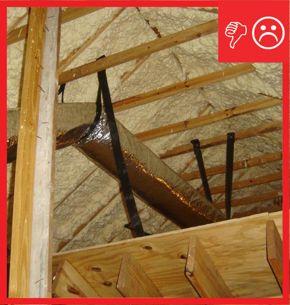
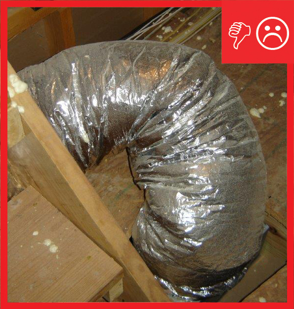
Wrong - The support strap for the duct is too tight and the radius of the turn is too sharp.
Image
Image
Image
Wrong -The duct does not have enough support so it is sagging and compressing the duct
Image
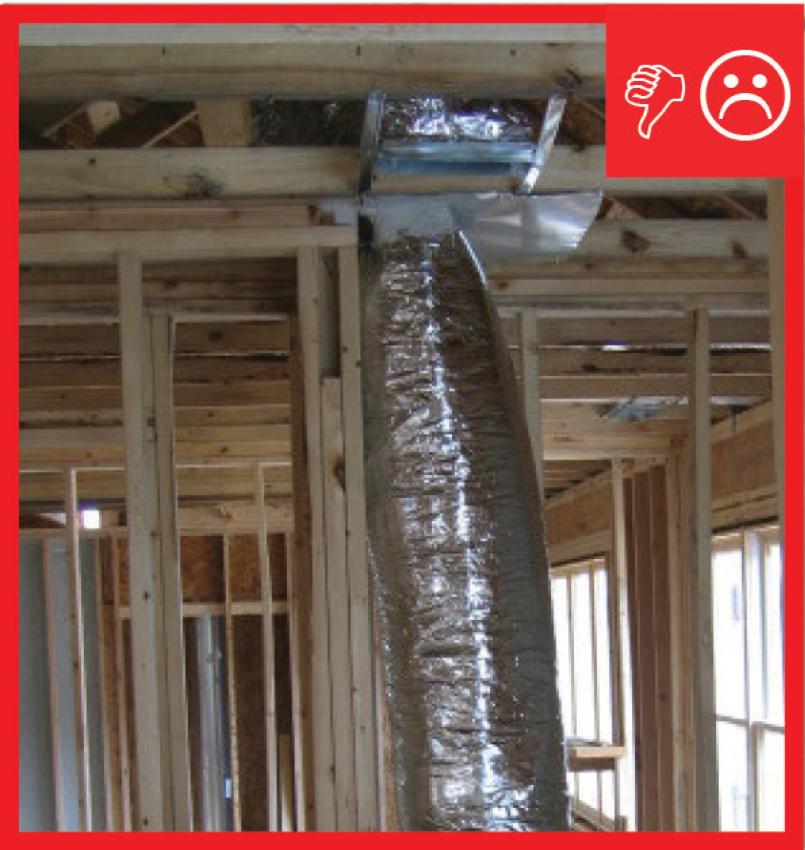
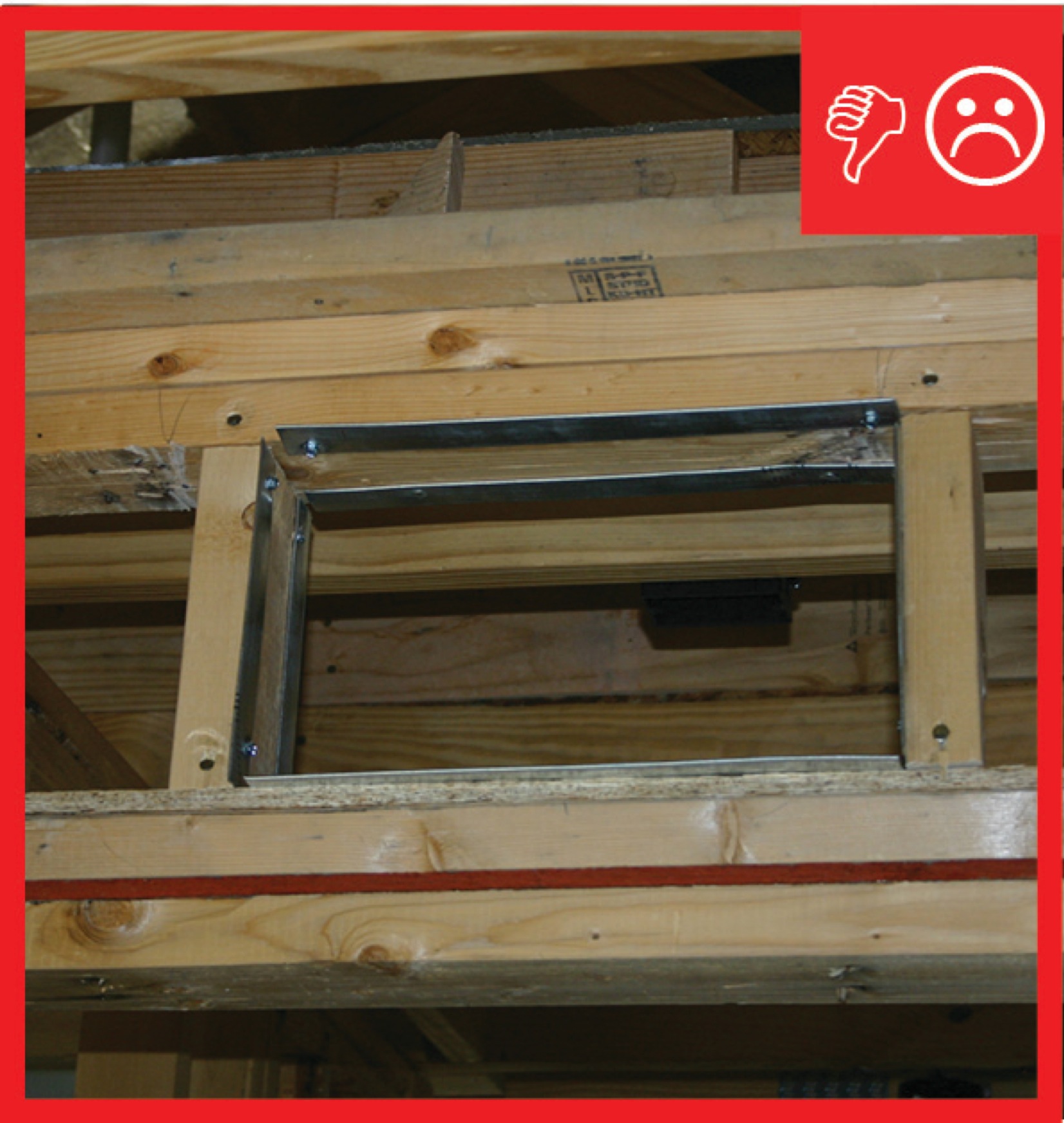
Wrong – Duct is pulling away from ceiling because it is not sealed to the ceiling
Image
Image
Image
Image
Image
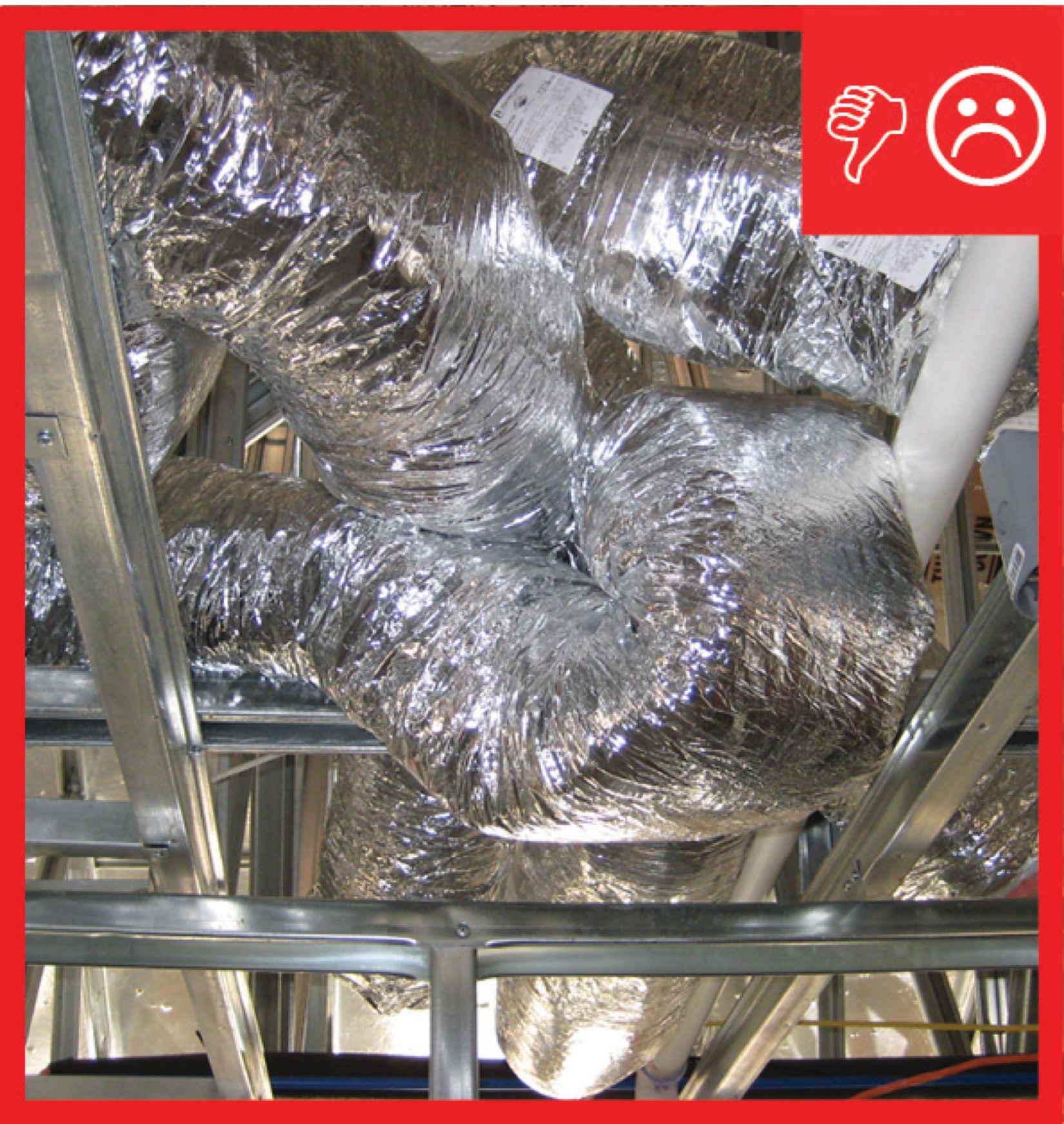
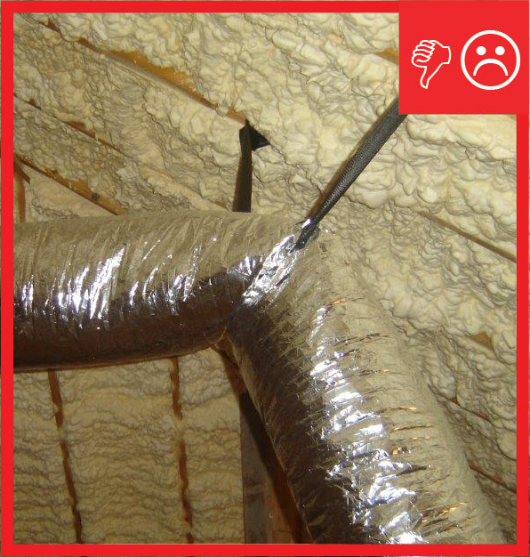
Wrong – These flex ducts are pulled taut, which is correct but they are inadequately supported with straps that are spaced too far apart and are too tight causing pinching of the insulation and turns are sharp rather than gradual.
Image
Wrong – Two combustion appliances are sharing a flue which could lead to backdrafting if one appliance is updated to a direct vent appliance and disconnected from shared chimney.
Image
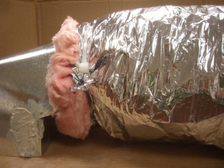
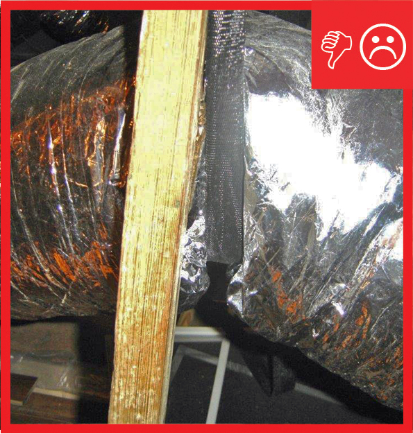
Wrong- A tie strap should not be used over the duct outer liner because it can compress the insulation. Tuck in the fibrous insulation and seal the outer liner to the connecting duct with mastic or foil tape (Steven Winter Associates 2013).
Image
Wrong: Open wall cavities in the un-air-sealed return plenum connect the plenum to attic spaces
Image
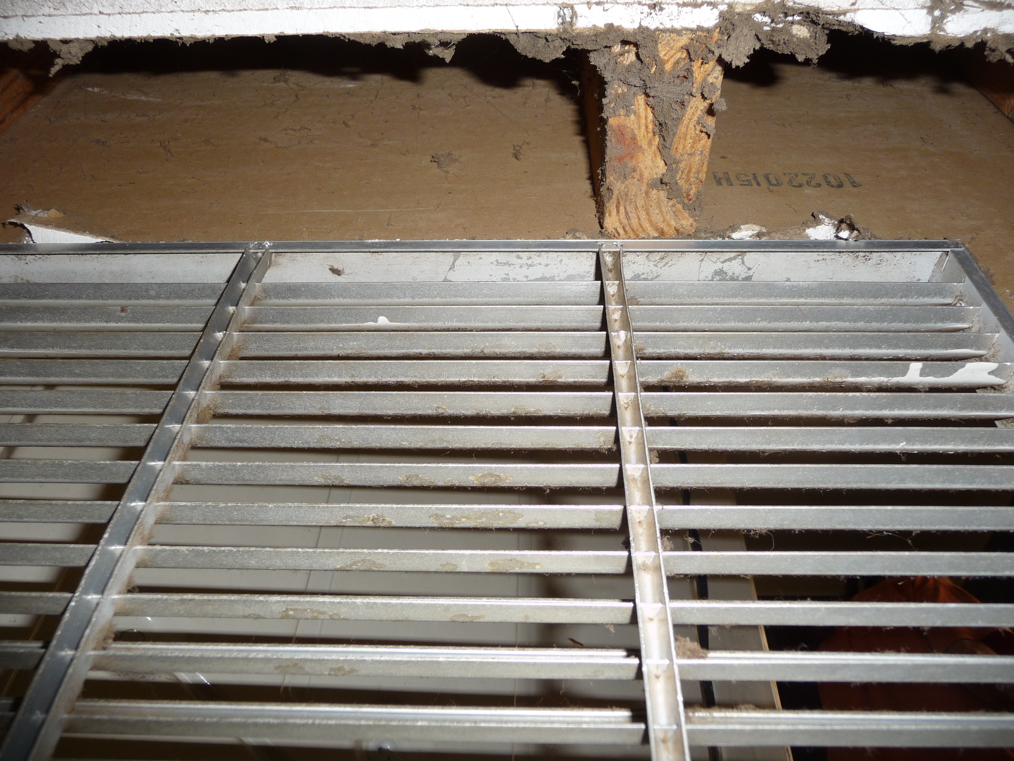
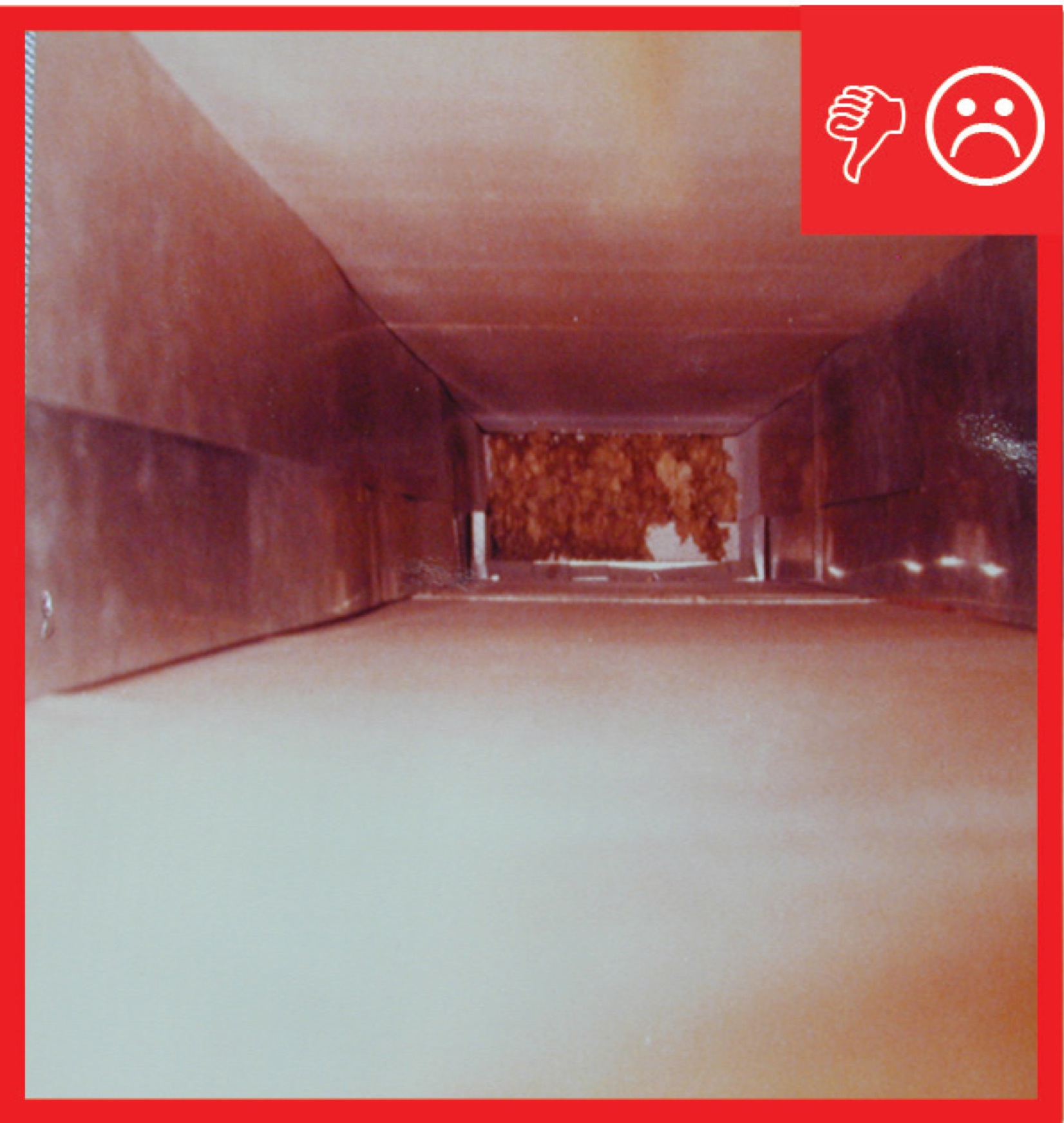
Wrong: open wall cavity connected to this return air plenum is allowing cellulose attic insulation to be pulled into the furnace
Image
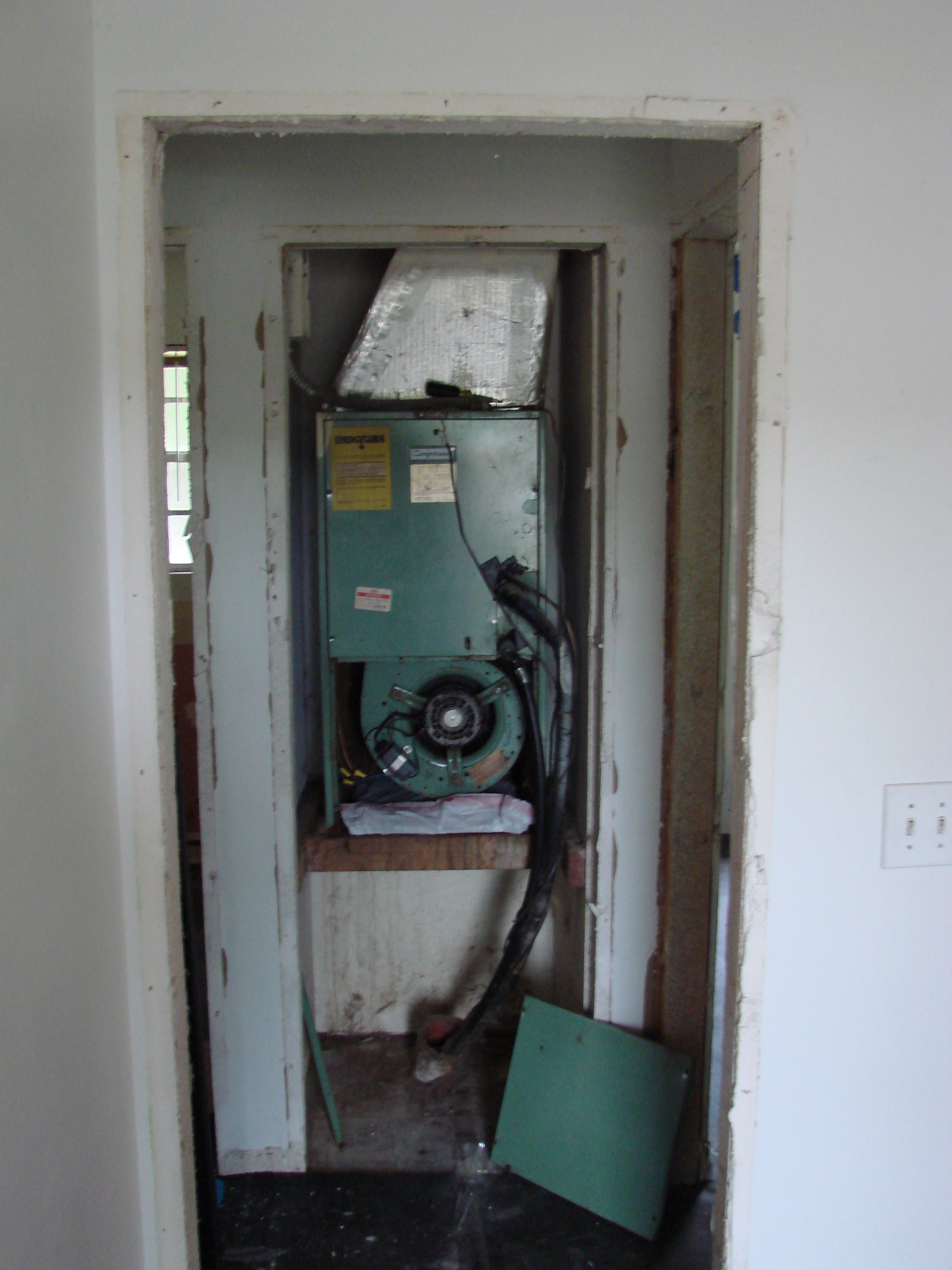
Wrong: The door and filter were removed, allowing unfiltered air to enter the air handler leading to premature failure of the system due to dirt accumulation.
Image
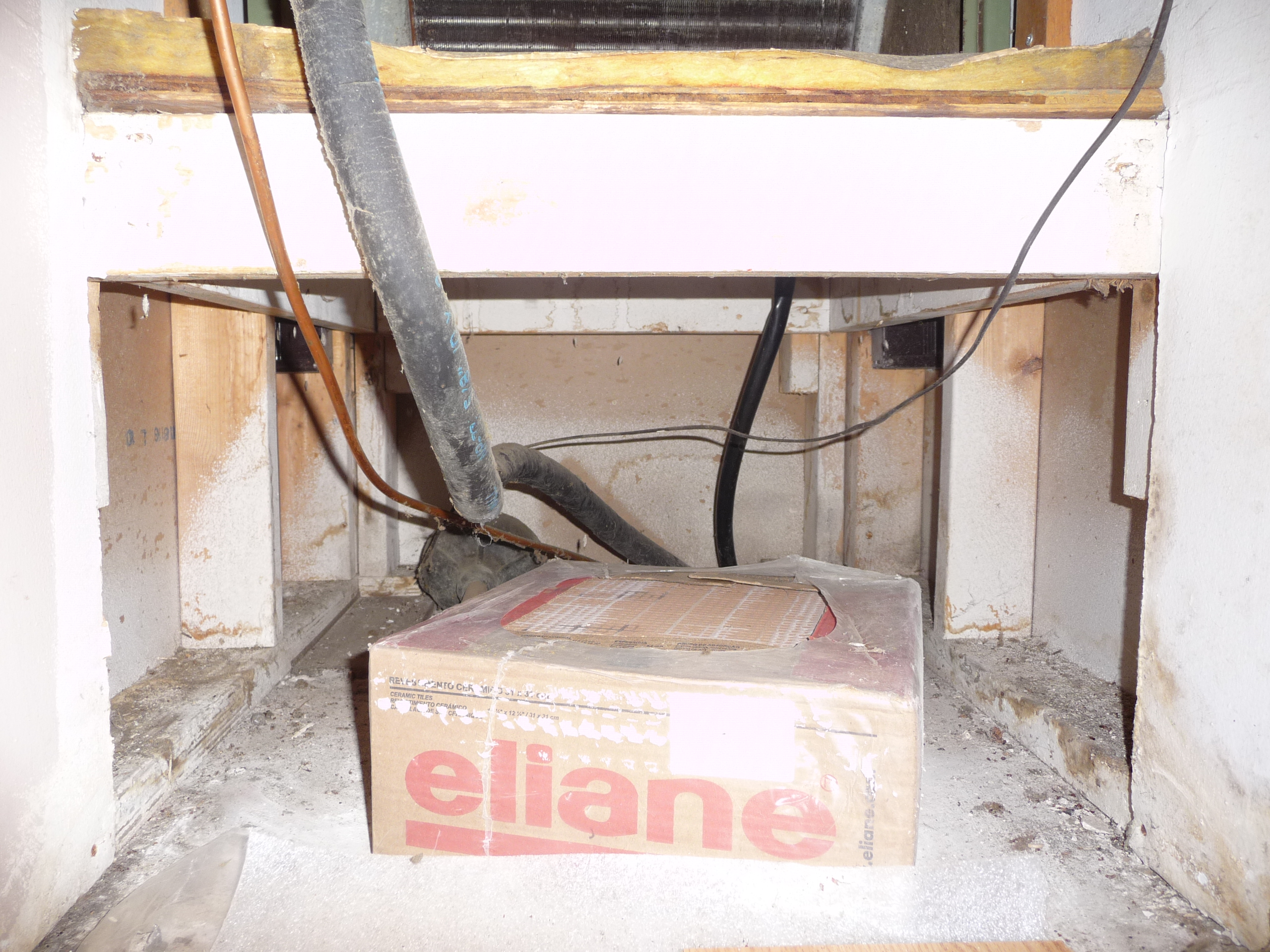
Wrong: The return plenum is not air sealed to separate it from the wall cavities and it should not be used for storage
Image
Wrong: This return air plenum is not lined and air sealed
Image
Wrong: This wall cavity is open to the attic allowing unconditioned, attic air to enter the HVAC system, bypassing the filter, and degrading system life and performance