

Image
Courtesy Of
Notes
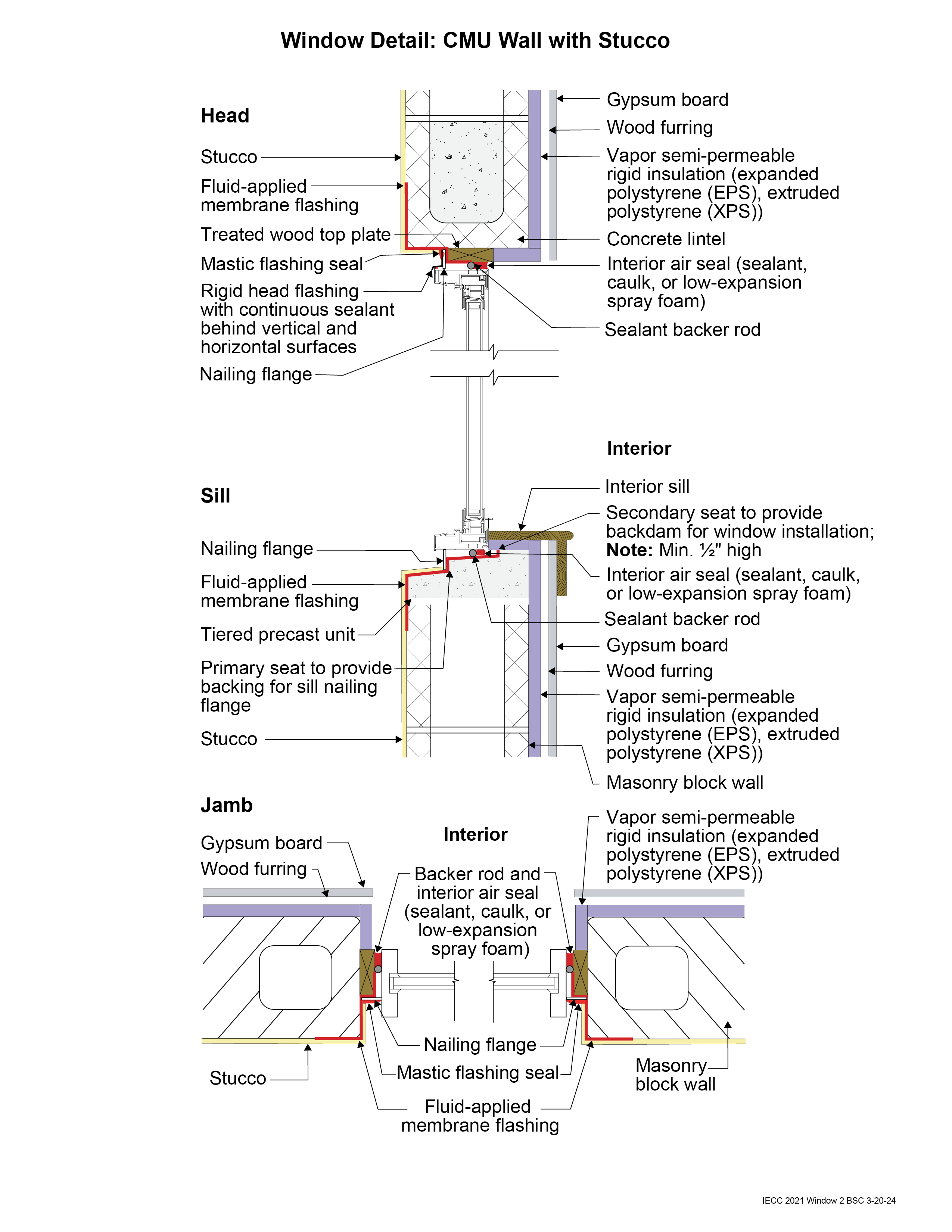
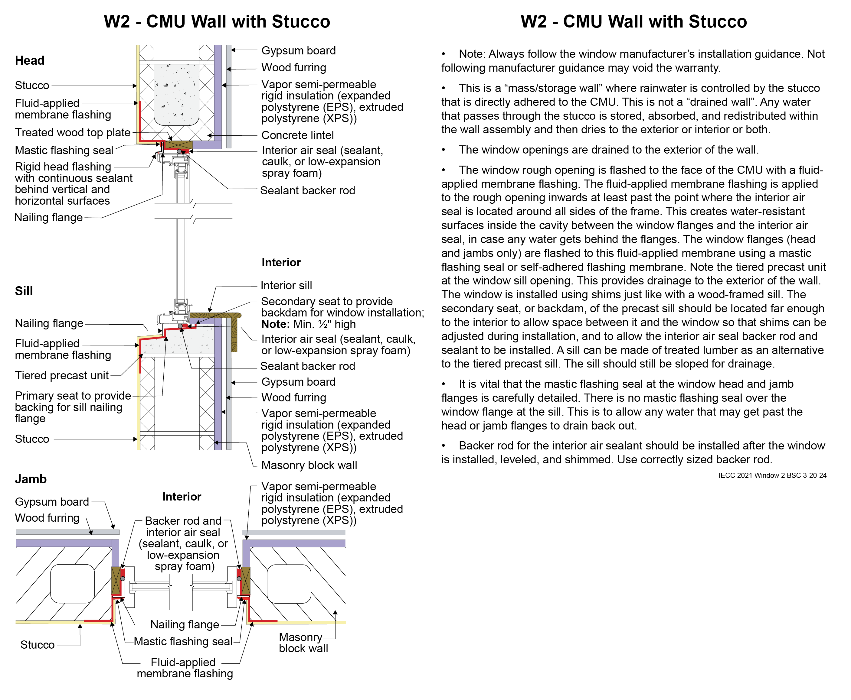
Window Detail 2 - CMU Wall with Stucco
- Note: Always follow the window manufacturer’s installation guidance. Not following manufacturer guidance may void the warranty.
- This is a “mass/storage wall” where rainwater is controlled by the stucco that is directly adhered to the CMU. This is not a “drained wall”. Any water that passes through the stucco is stored, absorbed, and redistributed within the wall assembly and then dries to the exterior or interior or both.
- The window openings are drained to the exterior of the wall.
- The window rough opening is flashed to the face of the CMU with a fluid-applied membrane flashing. The fluid-applied membrane flashing is applied to the rough opening inwards at least past the point where the interior air seal is located around all sides of the frame. This creates water-resistant surfaces inside the cavity between the window flanges and the interior air seal, in case any water gets behind the flanges. The window flanges (head and jambs only) are flashed to this fluid-applied membrane using a mastic flashing seal or self-adhered flashing membrane. Note the tiered precast unit at the window sill opening. This provides drainage to the exterior of the wall. The window is installed using shims just like with a wood-framed sill. The secondary seat, or backdam, of the precast sill should be located far enough to the interior to allow space between it and the window so that shims can be adjusted during installation, and to allow the interior air seal backer rod and sealant to be installed. A sill can be made of treated lumber as an alternative to the tiered precast sill. The sill should still be sloped for drainage.
- It is vital that the mastic flashing seal at the window head and jamb flanges is carefully detailed. There is no mastic flashing seal over the window flange at the sill. This is to allow any water that may get past the head or jamb flanges to drain back out.
- Backer rod for the interior air sealant should be installed after the window is installed, leveled, and shimmed. Use correctly sized backer rod.
Window Drawing image + notes (png)
(688.12 KB)
Window Drawing + notes (landscape)
(574.78 KB)
Window Drawing + notes (portrait pdf)
(576.81 KB)