

Image
Courtesy Of
Notes
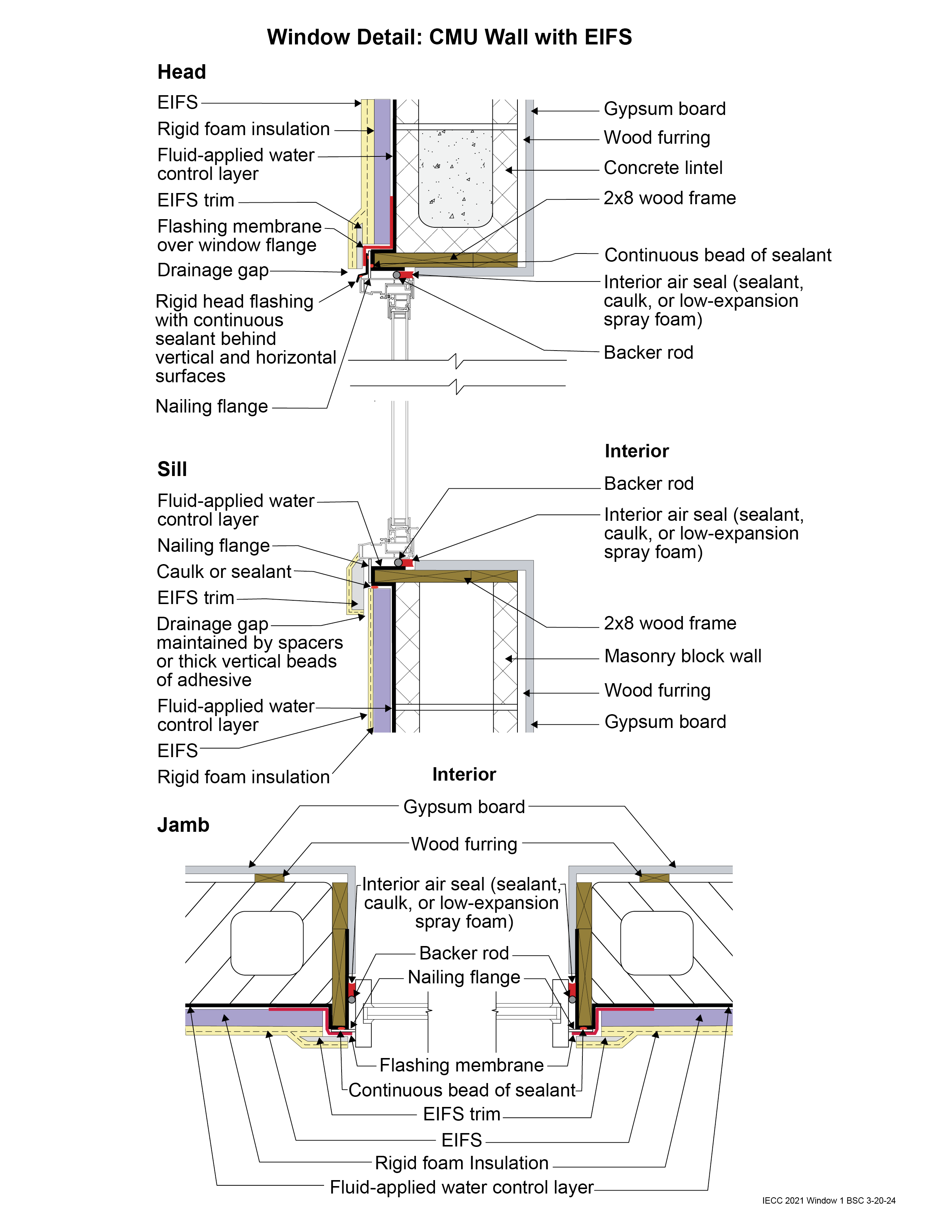
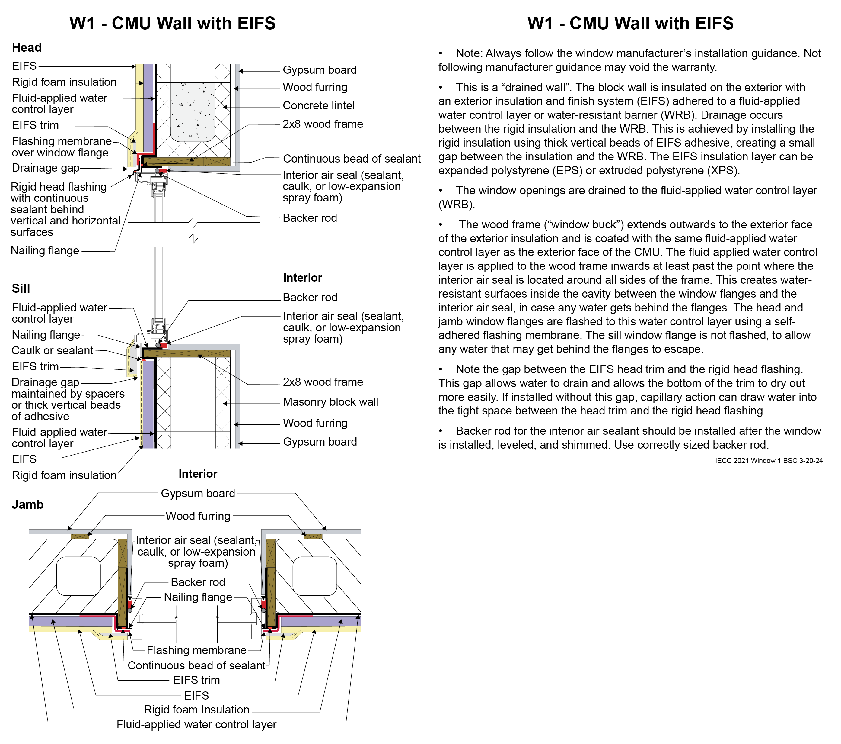
Window Detail 1 - CMU Wall with EIFS
- Note: Always follow the window manufacturer’s installation guidance. Not following manufacturer guidance may void the warranty.
- This is a “drained wall”. The block wall is insulated on the exterior with an exterior insulation and finish system (EIFS) adhered to a fluid-applied water control layer or water-resistant barrier (WRB). Drainage occurs between the rigid insulation and the WRB. This is achieved by installing the rigid insulation using thick vertical beads of EIFS adhesive, creating a small gap between the insulation and the WRB. The EIFS insulation layer can be expanded polystyrene (EPS) or extruded polystyrene (XPS).
- The window openings are drained to the fluid-applied water control layer (WRB).
- The wood frame (“window buck”) extends outwards to the exterior face of the exterior insulation and is coated with the same fluid-applied water control layer as the exterior face of the CMU. The fluid-applied water control layer is applied to the wood frame inwards at least past the point where the interior air seal is located around all sides of the frame. This creates water-resistant surfaces inside the cavity between the window flanges and the interior air seal, in case any water gets behind the flanges. The head and jamb window flanges are flashed to this water control layer using a self-adhered flashing membrane. The sill window flange is not flashed, to allow any water that may get behind the flanges to escape.
- Note the gap between the EIFS head trim and the rigid head flashing. This gap allows water to drain and allows the bottom of the trim to dry out more easily. If installed without this gap, capillary action can draw water into the tight space between the head trim and the rigid head flashing.
- Backer rod for the interior air sealant should be installed after the window is installed, leveled, and shimmed. Use correctly sized backer rod.
Window Drawing image + notes (png)
(691.64 KB)
Window Drawing + notes (tabloid pdf)
(569.64 KB)
Window Drawing + notes (portrait pdf)
(573.32 KB)