

Introduction
DIY guide showing how to pick a replacement air filter and how to replace the filter in home’s HVAC system when the air filter is located in a return grille in a ceiling, floor, or wall.
Why
Replacing the air filter in your home’s HVAC (heating, ventilation, and air conditioning) system every 3 to 6 months ensures the equipment has unrestricted airflow which is important for heating and cooling performance as well as maintaining good indoor air quality.
What You'll Need
- A replacement air filter
- A flat-head and a Phillip screwdriver
- A step stool or ladder to reach the air filter grille
- 1 in. wide masking tape
1. Turn off the HVAC system at the thermostat.
2. Locate the filter.
All central furnaces and heat pumps have a filter. The filter may be in a filter slot at the furnace cabinet between the return plenum and the furnace. If that is where your furnace filter is located, see the Building America Solution Center DIY guide Replace Air Filter Located in Furnace or Central Heat Pump Air Filter Slot. If your furnace filter is located just behind the return grille, read on. The return grille is a large rectangular metal grille approximately 20x25 inches installed in a central location in a ceiling, wall, or floor of the home (Figure 1). The return grille is where stale air is pulled from the house to return to the furnace/air handler for heating or cooling. Some homes have more than one return grille; for example, there might be one located on each floor of a multi-story home, and each may have a filter installed.

Source
3. Access the filter.
Most return grilles have screws or levers that need to be turned to open the cover. Use a screwdriver if needed. If the filter grille is on the ceiling, use one hand to hold the grille while unlatching with the other hand so the metal grille won’t fall down abruptly (Figure 2).

Source
4. Remove the existing air filter.
Remove the existing air filter (Figure 3). Note the dimensions and MERV (minimum efficiency reporting value) rating printed on the cardboard frame. Dispose of the dirty filter. If you have a washable filter, follow the manufacturer’s instructions for cleaning; allow washable filters to dry completely before reinstalling.

Source
5. Measure the size of the filter space.
The filter you are replacing should have length and width dimensions printed on the cardboard frame. If it fits correctly, replace it with a filter of the same length and width dimensions. Measure the filter space to verify the length and width dimensions and also measure the depth to determine the maximum thickness of filter allowable (Figure 4).

Source
6. Choose a replacement filter.
If the filter slot will accommodate a thicker filter, you may want to install a filter that is thicker than the one you are replacing. Ideally you will want to install the thickest air filter that the filter space can accommodate.
If, for example, by measuring, you determine that the space will accommodate an air filter that is 2 inches thick (as in Figure 4), even if the filter you removed was only 1 inch thick, it would be better to replace it with a filter that is 2 inches thick. This is because the deeper the pleats on the air filter, the more actual surface area the filter has.
The ability of furnace filters to filter out particles is rated on a MERV (Minimum Efficiency Reporting Value) scale:
- MERV 1–4: Catches large particles like lint, dust mites, and pollen.
- MERV 5–8: Captures finer dust particles, pet dander, and mold spores.
- MERV 9–12: Filters out auto emissions, lead dust, and larger bacteria.
- MERV 13–16: Traps very fine particles, including smoke, sneeze droplets, and bacteria.
- HEPA-level (MERV 17-20): Used in hospitals and cleanrooms to filter ultrafine particles, including viruses and other extremely small particles.
Higher MERV filters are better at filtering out small particles but they can also clog more quickly, restricting air flow, causing increased wear on your HVAC system, and limiting its ability to heat and cool. A filter with deeper pleats has more surface area and therefore provides better airflow for a longer time period before needing to be replaced. When shopping for a filter, pay attention to the MERV rating (Figure 5), the thickness, and the actual dimensions of the filter not just the nominal size. Check with your HVAC service company before switching from a MERV 1 to a MERV 13 or higher filter to make sure it won’t adversely impact your HVAC system’s performance.

Source
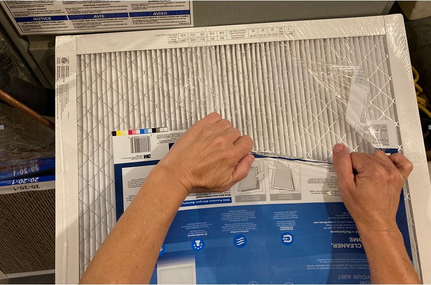
7. Install the new air filter.
Remove the plastic wrap but not the cardboard frame of the filter (Figure 6). Write the installation date on the cardboard frame on the side of the filter that will be visible when the filter is installed to help you keep track of when it was last changed. Pay attention to the airflow direction arrows (Figure 7) when installing the new air filter. The arrows should point into the duct.
Source

Source
8. Seal the perimeter with tape.
Tape the perimeter of the air filter to the grille using masking tape to block this pathway for air to bypass around the air filter (Figure 8).

Source
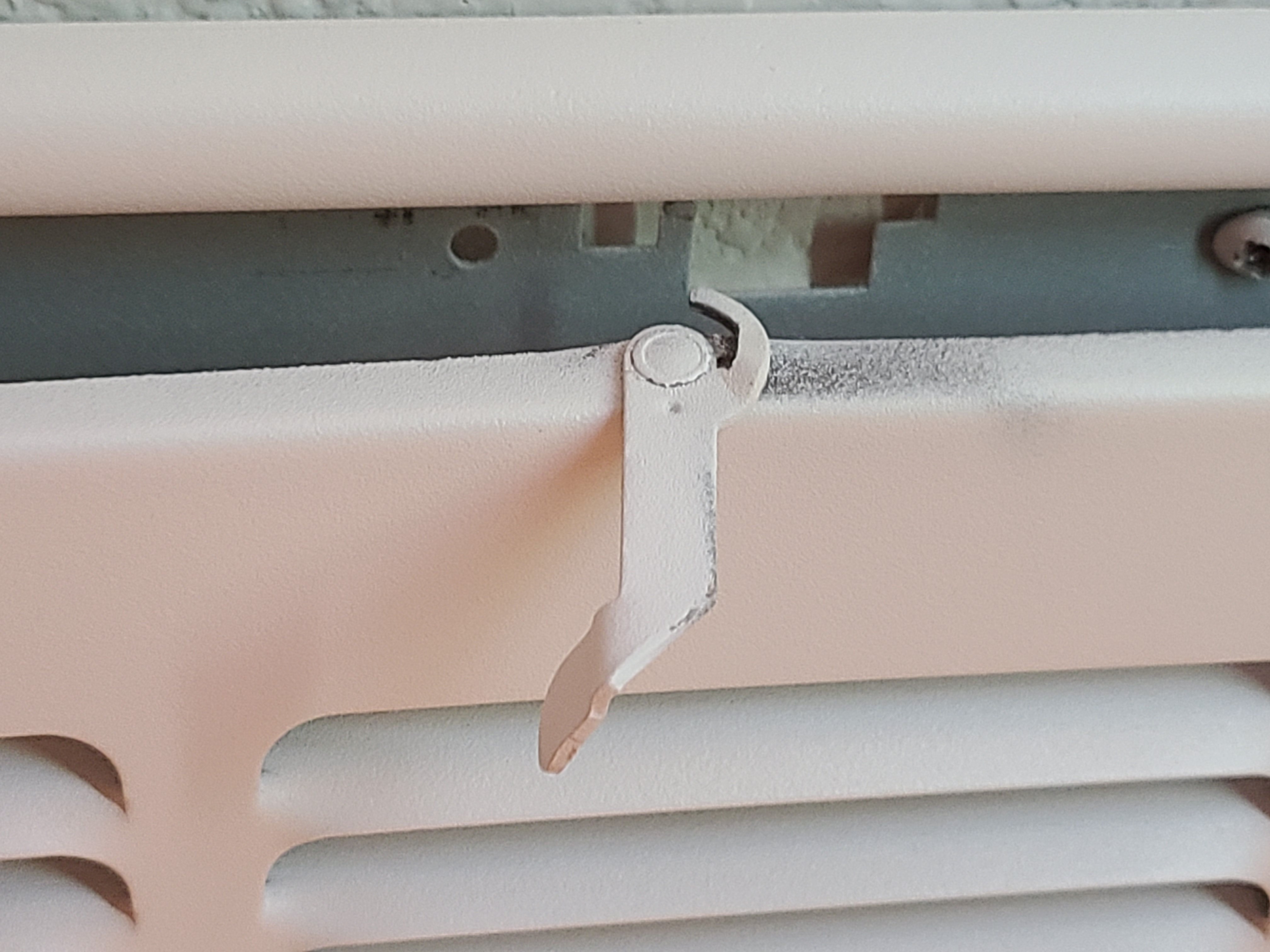
9. Close the grille cover.
Re-position the grille cover over the return duct. Make sure it is sitting in the frame securely and check to make sure the latch has hooked onto the metal frame or that the screws have been securely fastened (Figure 9).
Source
10. Turn the HVAC equipment back on.
Switch on the furnace or heat pump at the thermostat to return the system to the appropriate temperature and mode.