

Image
Courtesy Of
Notes
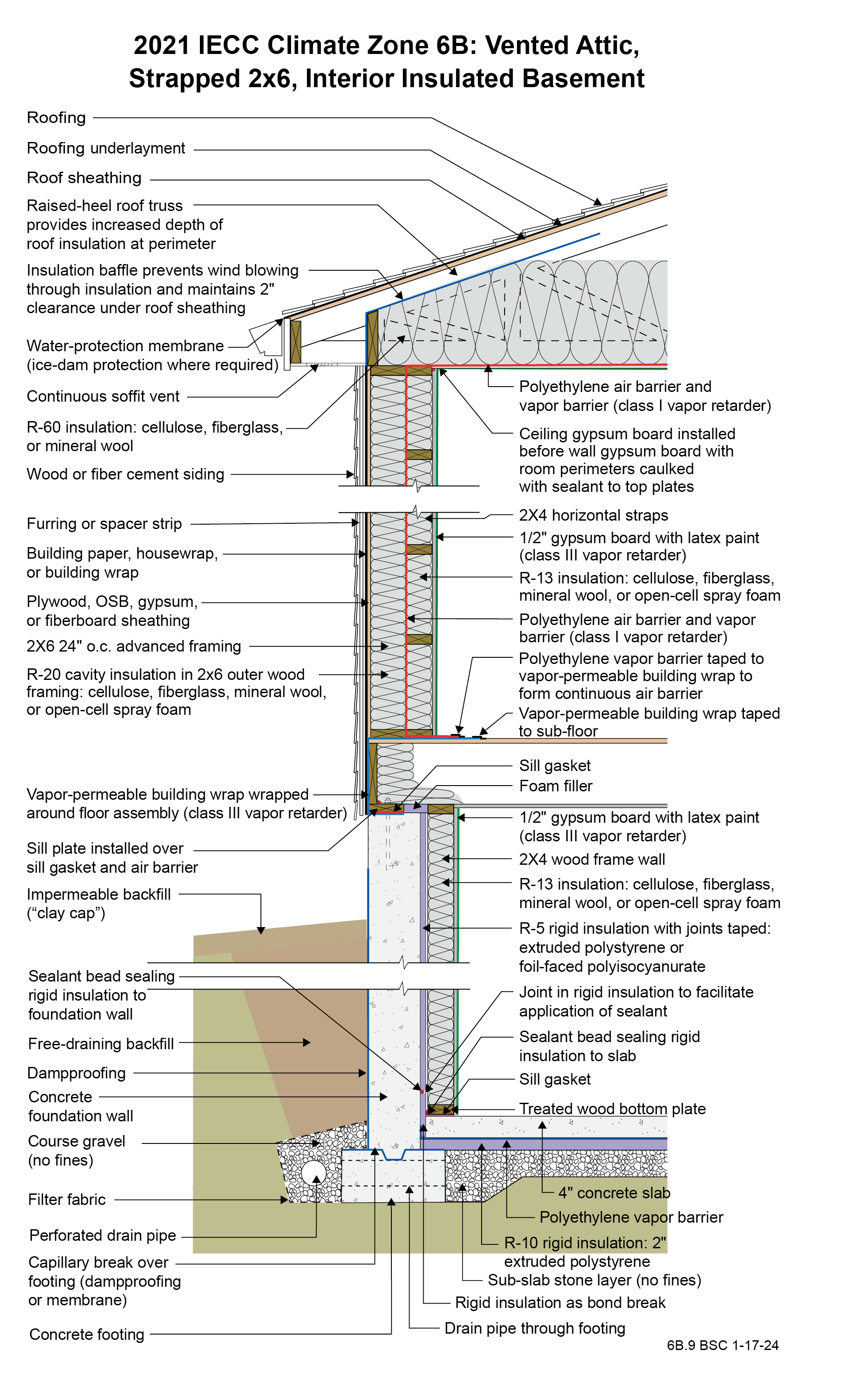
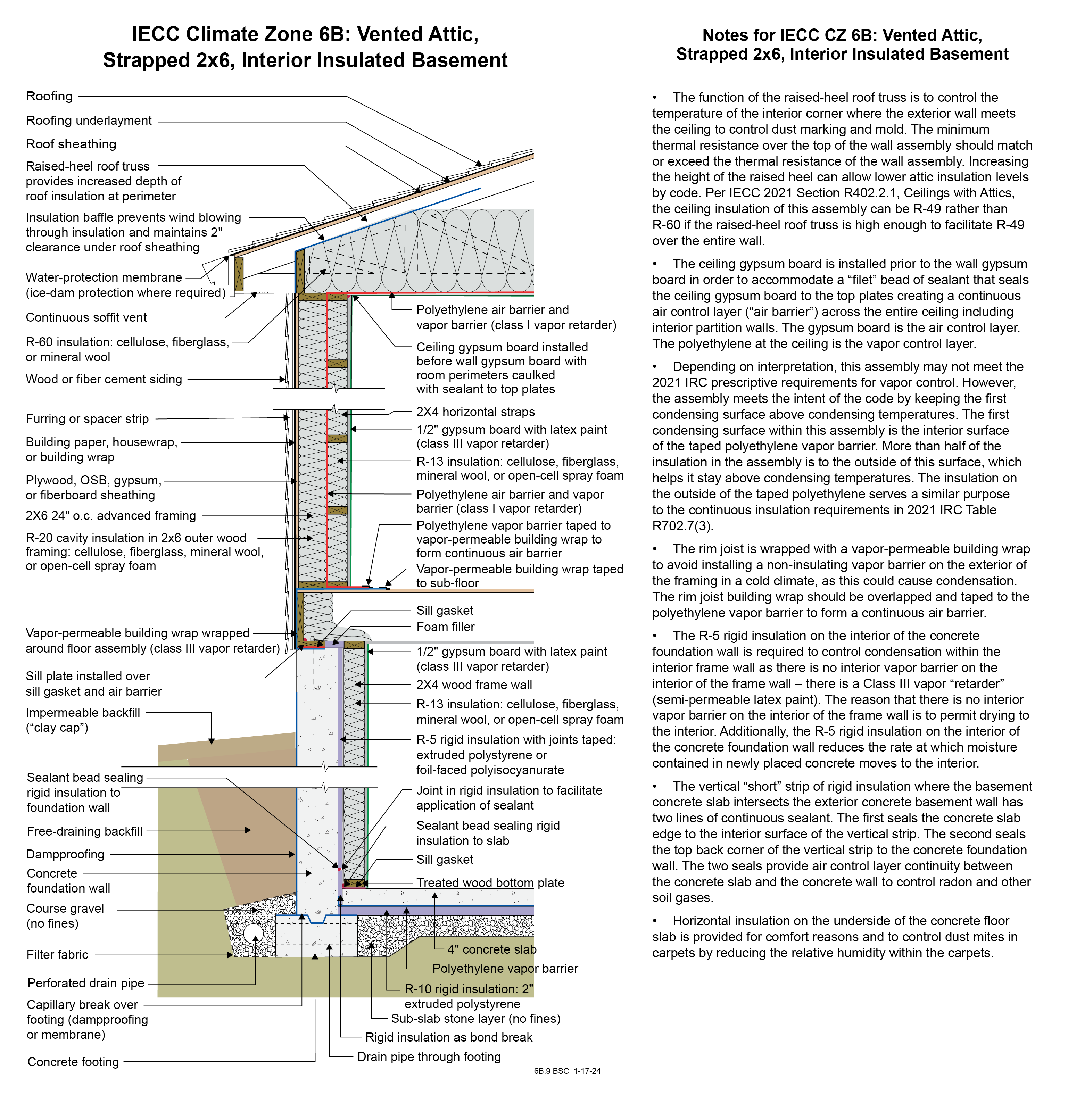
Drawing 6B.9: IECC CZ 6: Vented Attic, Strapped 2x6, Interior Insulated Basement
- The function of the raised-heel roof truss is to control the temperature of the interior corner where the exterior wall meets the ceiling to control dust marking and mold. The minimum thermal resistance over the top of the wall assembly should match or exceed the thermal resistance of the wall assembly. Increasing the height of the raised heel can allow lower attic insulation levels by code. Per IECC 2021 Section R402.2.1, Ceilings with Attics, the ceiling insulation of this assembly can be R-49 rather than R-60 if the raised-heel roof truss is high enough to facilitate R-49 over the entire wall.
- The ceiling gypsum board is installed prior to the wall gypsum board in order to accommodate a “filet” bead of sealant that seals the ceiling gypsum board to the top plates creating a continuous air control layer (“air barrier”) across the entire ceiling including interior partition walls. The gypsum board is the air control layer. The polyethylene at the ceiling is the vapor control layer.
- Depending on interpretation, this assembly may not meet the 2021 IRC prescriptive requirements for vapor control. However, the assembly meets the intent of the code by keeping the first condensing surface above condensing temperatures. The first condensing surface within this assembly is the interior surface of the taped polyethylene vapor barrier. More than half of the insulation in the assembly is to the outside of this surface, which helps it stay above condensing temperatures. The insulation on the outside of the taped polyethylene serves a similar purpose to the continuous insulation requirements in 2021 IRC Table R702.7(3).
- The rim joist is wrapped with a vapor-permeable building wrap to avoid installing a non-insulating vapor barrier on the exterior of the framing in a cold climate, as this could cause condensation. The rim joist building wrap should be overlapped and taped to the polyethylene vapor barrier to form a continuous air barrier.
- The R-5 rigid insulation on the interior of the concrete foundation wall is required to control condensation within the interior frame wall as there is no interior vapor barrier on the interior of the frame wall – there is a Class III vapor “retarder” (semi-permeable latex paint). The reason that there is no interior vapor barrier on the interior of the frame wall is to permit drying to the interior. Additionally, the R-5 rigid insulation on the interior of the concrete foundation wall reduces the rate at which moisture contained in newly placed concrete moves to the interior.
- The vertical “short” strip of rigid insulation where the basement concrete slab intersects the exterior concrete basement wall has two lines of continuous sealant. The first seals the concrete slab edge to the interior surface of the vertical strip. The second seals the top back corner of the vertical strip to the concrete foundation wall. The two seals provide air control layer continuity between the concrete slab and the concrete wall to control radon and other soil gases.
- Horizontal insulation on the underside of the concrete floor slab is provided for comfort reasons and to control dust mites in carpets by reducing the relative humidity within the carpets.
Drawing + notes (portrait pdf)
(597.81 KB)
Drawing + notes (tabloid pdf)
(596.7 KB)
Drawing image + notes (png)
(1 MB)