

Image
Courtesy Of
Notes
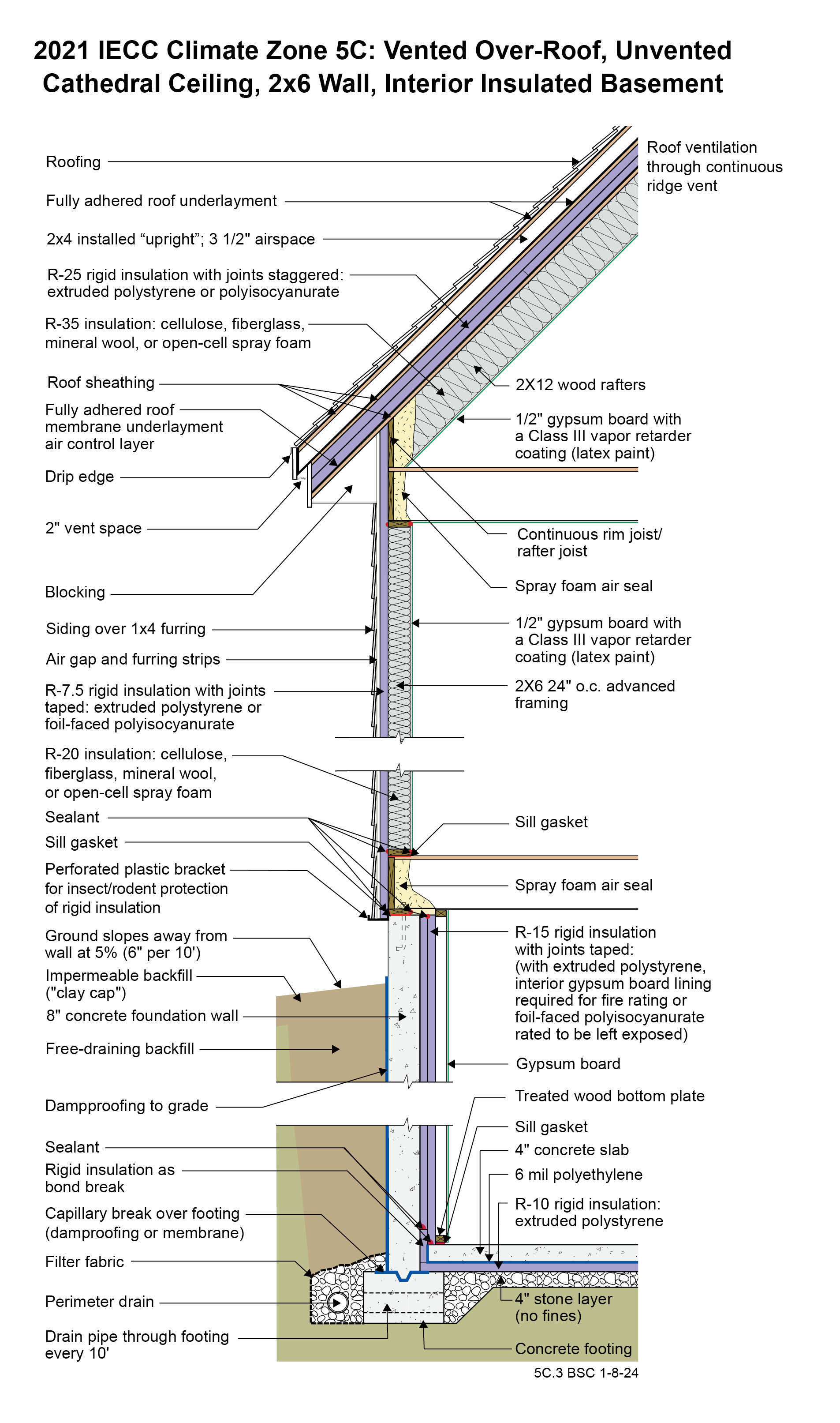
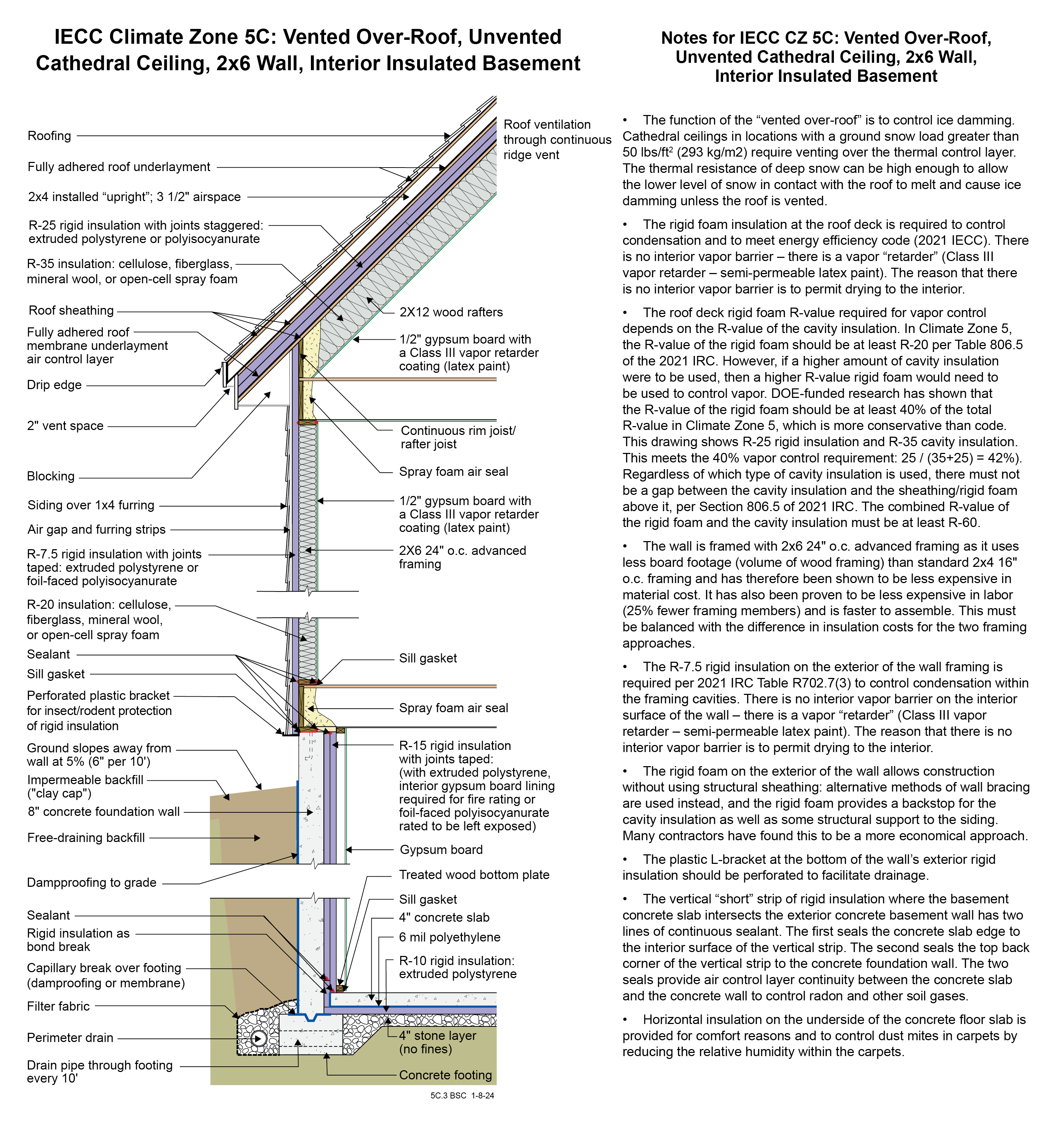
Drawing 5C.3: IECC CZ 5: Vented Over Roof, Unvented Cathedral Ceiling, 2x6 Wall, Interior Insulated Basement
- The function of the “vented over-roof” is to control ice damming. Cathedral ceilings in locations with a ground snow load greater than 50 lbs/ft2 (293 kg/m2) require venting over the thermal control layer. The thermal resistance of deep snow can be high enough to allow the lower level of snow in contact with the roof to melt and cause ice damming unless the roof is vented.
- A low-permeance roofing underlayment (less than 1 perm) is recommended for this roof type in this climate to reduce water diffusion through the underlayment to the sheathing.
- The rigid foam insulation at the roof deck is required to control condensation and to meet energy efficiency code (2021 IECC). There is no interior vapor barrier – there is a vapor “retarder” (Class III vapor retarder – semi-permeable latex paint). The reason that there is no interior vapor barrier is to permit drying to the interior.
- The roof deck rigid foam R-value required for vapor control depends on the R-value of the cavity insulation. In Climate Zone 5, the R-value of the rigid foam should be at least R-20 per Table 806.5 of the 2021 IRC. However, if a higher amount of cavity insulation were to be used, then a higher R-value rigid foam would need to be used to control vapor. DOE-funded research has shown that the R-value of the rigid foam should be at least 40% of the total R-value in Climate Zone 5, which is more conservative than code. This drawing shows R-25 rigid insulation and R-35 cavity insulation. This meets the 40% vapor control requirement: 25 / (35+25) = 42%). Regardless of which type of cavity insulation is used, there must not be a gap between the cavity insulation and the sheathing/rigid foam above it, per Section 806.5 of 2021 IRC. The combined R-value of the rigid foam and the cavity insulation must be at least R-60.
- Note that if this assembly has an attic space, Section R402.2.1 of the 2021 IECC may apply, depending on the interpretation of the local code official. If so, R-49 could be used over the attic rather than R-60 as long as the R-49 insulation extended over the full width of the exterior wall top plate.
- The wall is framed with 2x6 24” o.c. advanced framing as it uses less board footage (volume of wood framing) than standard 2x4 16” o.c. framing and has therefore been shown to be less expensive in material cost. It has also been proven to be less expensive in labor (25% fewer framing members) and is faster to assemble. This must be balanced with the difference in insulation costs for the two framing approaches.
- The R-7.5 rigid insulation on the exterior of the wall framing is required per 2021 IRC Table R702.7(3) to control condensation within the framing cavities. There is no interior vapor barrier on the interior surface of the wall – there is a vapor “retarder” (Class III vapor retarder – semi-permeable latex paint). The reason that there is no interior vapor barrier is to permit drying to the interior.
- The rigid foam on the exterior of the wall allows construction without using structural sheathing: alternative methods of wall bracing are used instead, and the rigid foam provides a backstop for the cavity insulation as well as some structural support to the siding. Many contractors have found this to be a more economical approach.
- The plastic L-bracket at the bottom of the wall’s exterior rigid insulation should be perforated to facilitate drainage.
- The vertical “short” strip of rigid insulation where the basement concrete slab intersects the exterior concrete basement wall has two lines of continuous sealant. The first seals the concrete slab edge to the interior surface of the vertical strip. The second seals the top back corner of the vertical strip to the concrete foundation wall. The two seals provide air control layer continuity between the concrete slab and the concrete wall to control radon and other soil gases.
- Horizontal insulation on the underside of the concrete floor slab is provided for comfort reasons and to control dust mites in carpets by reducing the relative humidity within the carpets.
Drawing + notes (portrait pdf)
(618.97 KB)
Drawing + notes (tabloid pdf)
(618.04 KB)
Drawing image + notes (png)
(951.29 KB)