Materials Cost: FREE
Difficulty Level: 1

Introduction

Missing flashing can lead to water infiltration and major damage and rot that may be hidden beneath the walls or roof.

Why

Water damage can bankrupt you quickly. When water gets into walls and attics, it can encourage mold and rot in building materials, so it is important to regularly look at the walls and roof for missing flashing. Flashing is a thin, waterproof material, often metal, rubber, or vinyl, used to create a barrier against water intrusion at vulnerable junctions and penetrations in a building's exterior, such as where a roof meets a wall, or around pipes, vents, and windows. Flashing directs water down and out of a building (Figure 1). Look for drip edge flashing along the bottom edge of the roofing, look for step and kick-out flashing where walls meet roofs. Look for flashing boots around vent pipes and stacks. Also look for gutters and downspouts, head flashing above doors and windows, through-the-wall flashing above foundations, and ledger board flashing for decks. Hire a contractor if any of these details are missing or need attention.
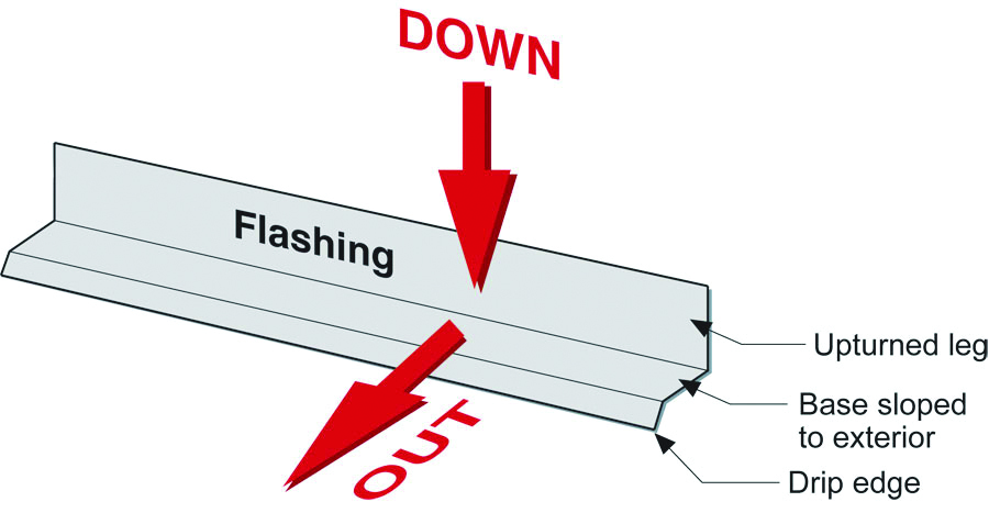
The “down” and “out” approach to flashing – metal flashing directs water down and out of building assemblies
Source
Author(s)
Lstiburek Joseph W
Organization(s)
Building Science Corporation,
BSC
Description

Guide providing information about controlling rainwater through use of drainage planes.

Figure 1. Flashing directs water down and out of buildings (Source: Building Science Corporation).

What You'll Need

  • Ladder or step stool
  • Gloves (optional)
  • Exterior-grade caulk
  • Flathead screwdriver (optional)

1. Roof: Look at gutters.

Gutters are one of the key water-handling features of a home. Most homes, except those in very dry climates, could benefit from gutters to direct water off the roof and away from the foundation (Figure 2). Check that all of your gutters drain to downspouts and investigate where those downspouts go. They should drain below ground to a French drain or to daylight to a pop-up sprinkler in a low spot on your property. In older homes, they may drain through underground drain pipes out to the street or into the sewer, or they may attach to a short above-ground run out. Downspout extensions and splash blocks can be an effective way to handle drainage from gutters and downspouts, if they are connected (Figure 3) and if they direct water onto a yard that slopes away from the house to keep water from pooling by the foundation.
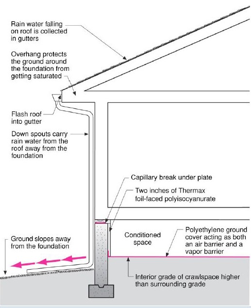
Comprehensive above-grade water management details for a crawlspace foundation include a capillary break over the crawlspace floor, slope the surface grade away, installing gutters that slope away, and capillary break under sill plate.
Source
Author(s)
Building Science Corporation
Organization(s)
BSC
Description

Information sheet about groundwater control.
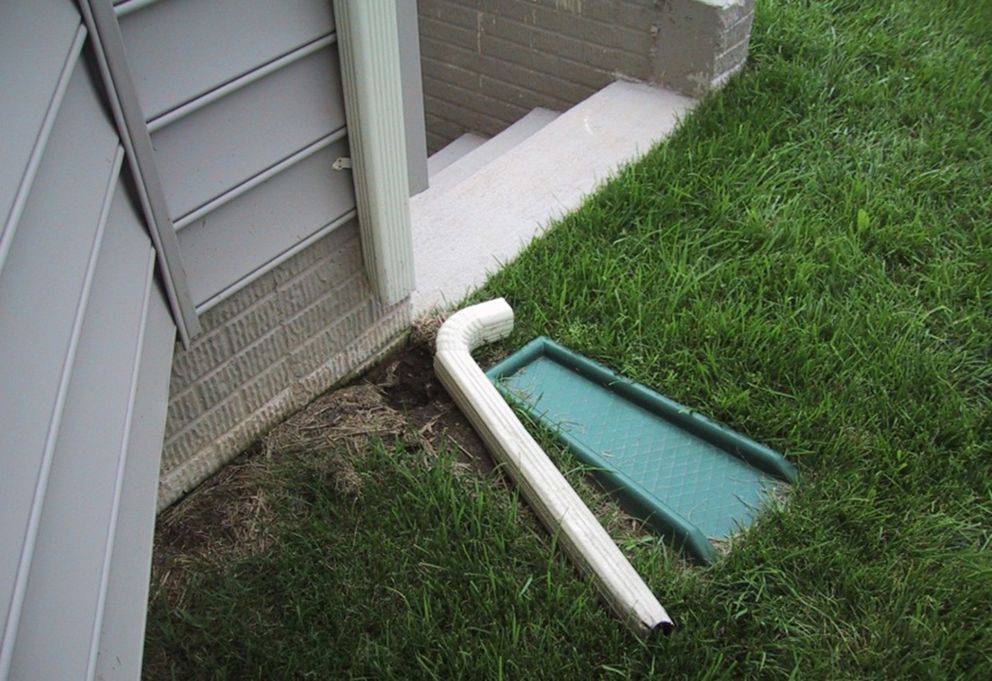
Figure 2. Gutters and downspouts direct water away from the foundation of the home (Source: Building Science Corporation).
Figure 3. Downspout extensions and splash blocks often get disconnected to mow the lawn, then fail to get reconnected, allowing water from the gutters to discharge directly next to the house and in this case to stairs leading to the basement (Source: Steve Easley & Associates).

If you have gutters, your roof’s metal drip edge flashing should extend into, not behind, the gutters. 

Gutters need to be cleaned out regularly to work well - twice a year if you have a lot of trees near by. Trees should be trimmed back so that branches don’t overhang roofs or brush against the gutters. Consider investing in a gutter screening product that keeps out debris but allows water to drain into the gutters.


2. Roof: Look for kickout flashing.

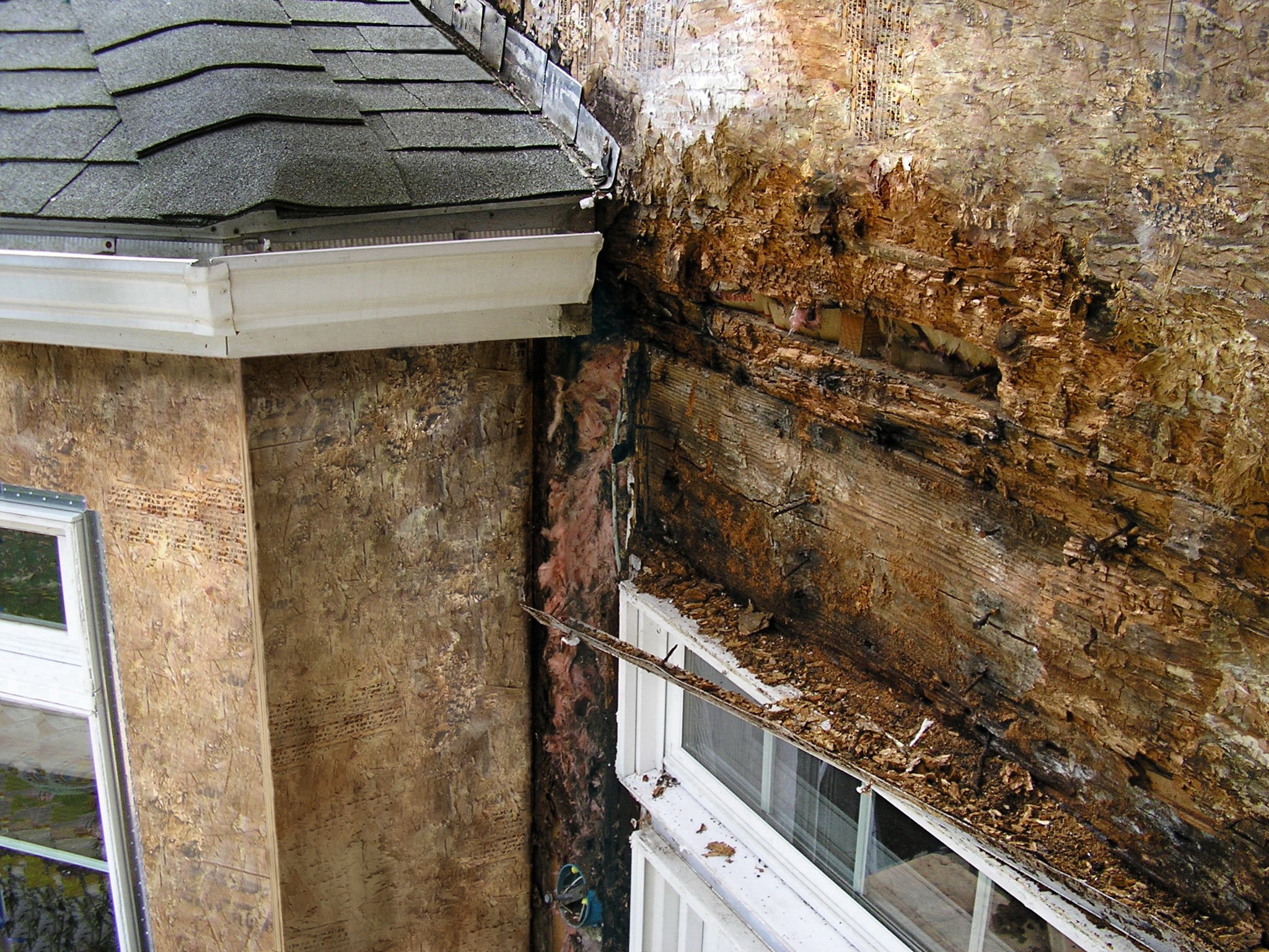
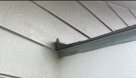
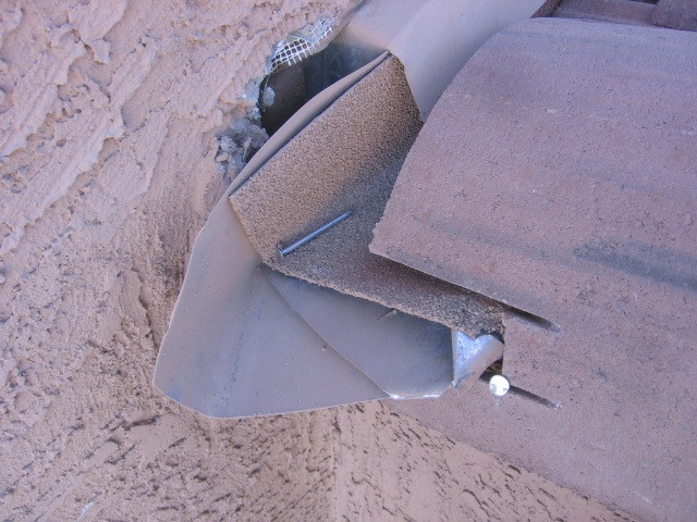
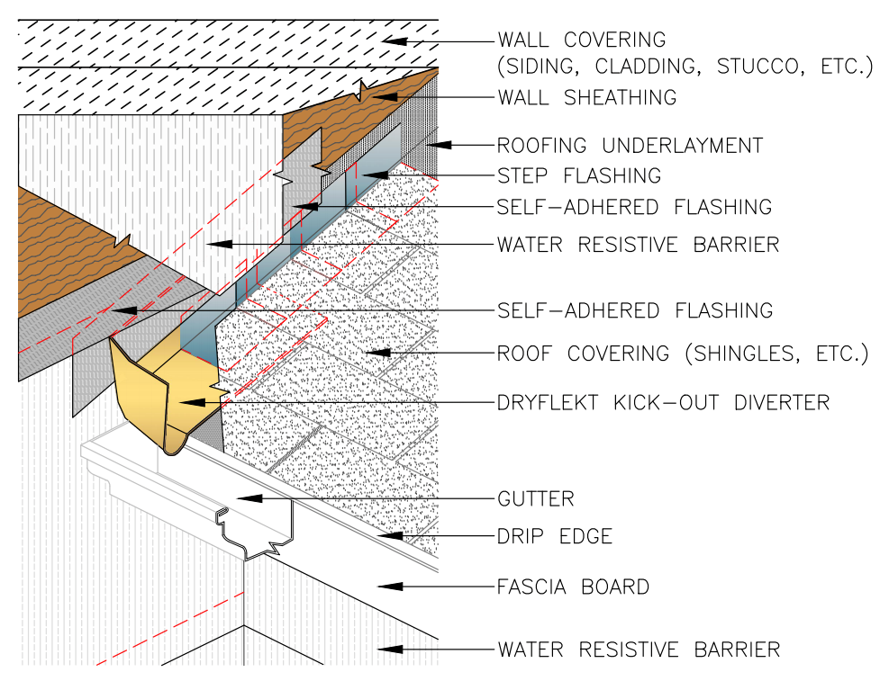
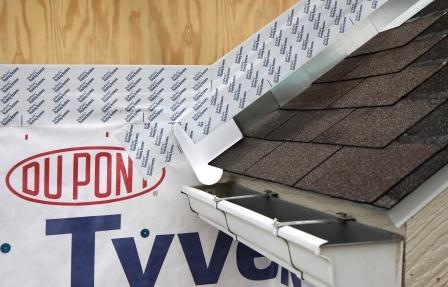
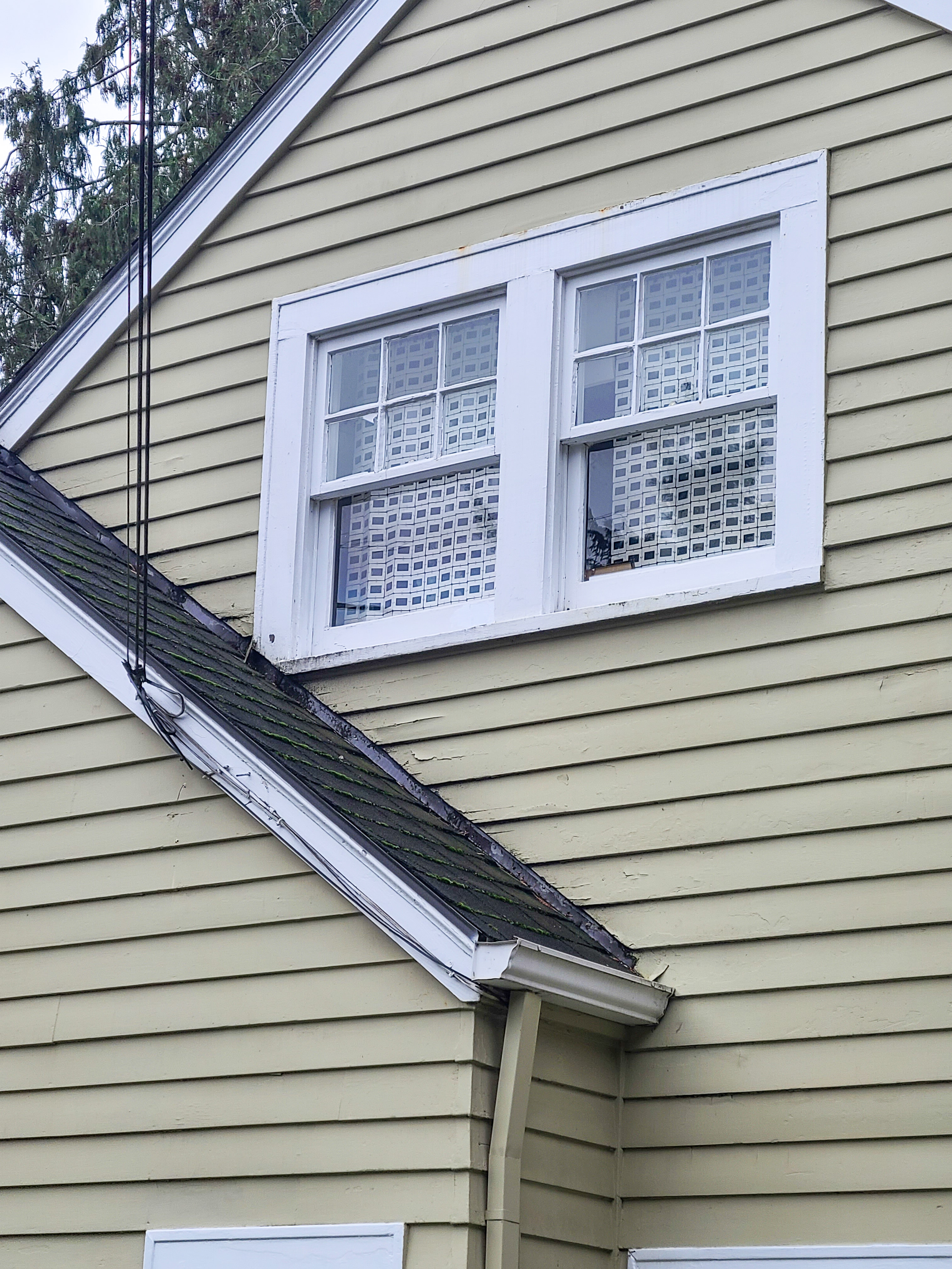
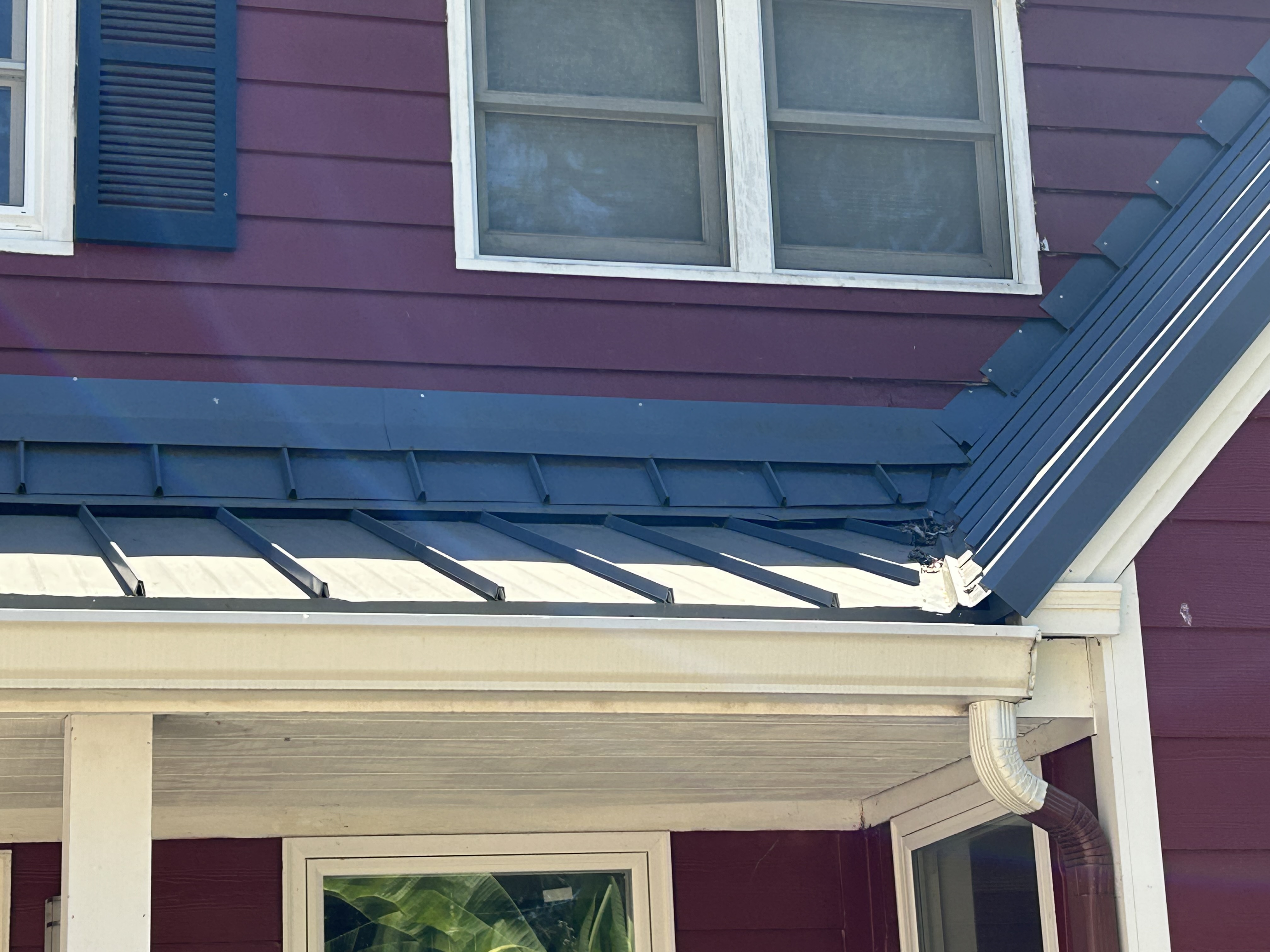
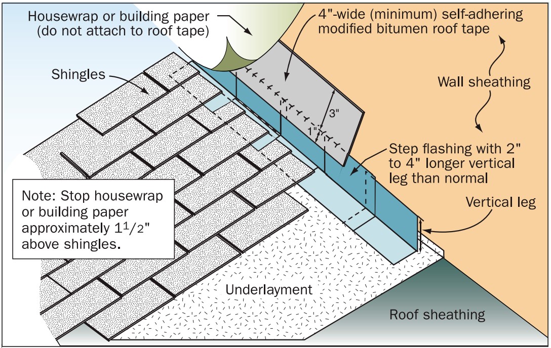
If your roof is multiple levels and you have areas where the roof meets a wall, you should have kickout flashing to direct water flowing down the roof along the wall to turn into the gutter rather than overflowing the gutter and running down the wall at that junction. Figures 4 and 5 show examples of wall-roof junctures that lack kick-out flashing. Every time it rains, water collects on the roof and flows down along the wall to the gutter, carrying with it debris. The concentrated flow of rainwater overflows the gutter and spills down onto the wall carrying debris that stains the wall. This onslaught of water is likely to eventually rot out the window trim and overcome any window flashing, getting inside the wall to cause more damage (Figure 6). Roofers or gutter installers will sometimes place bent pieces of sheet metal at the junction to try to divert water away from the wall (Figures 7 and 8), but field-fashioned kickout flashing is often woefully inadequate for the amount of water coming down the roof. Figures 9 and 10 show the proper size and integration of a commercially available kickout flashing product with step flashing, wall flashing, and roofing shingles.  
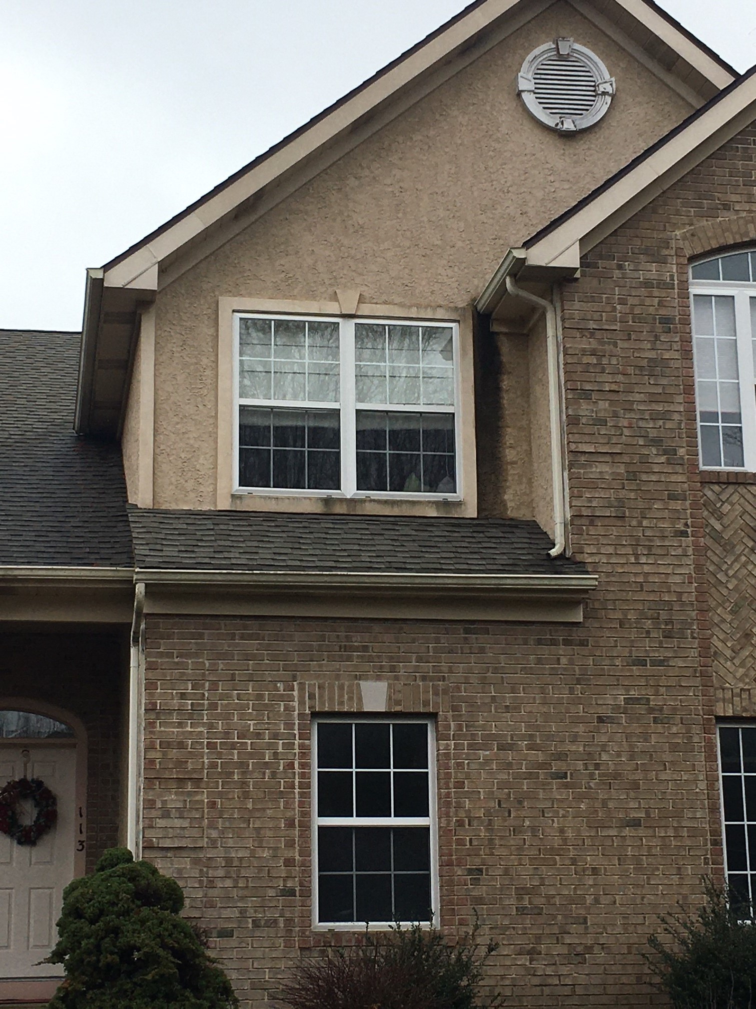
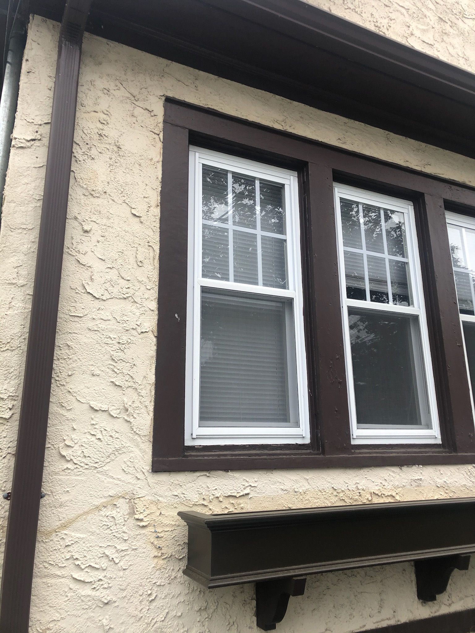
Wrong - Missing kick-out flashing to divert rainwater runoff into the gutter where the roof meets the wall has caused discoloration and water damage behind the stucco next to this second-story window.
Source
Figure 4. Missing kickout flashing where the upper gutter meets the gable has allowed water to pour down the wall along this window, staining the stucco siding and likely getting into seams along the window to cause water damage inside the wall (Source: PNNL).
Wrong - The gutter is missing kick-out flashing causing wall and window damage beneath it.
Source
Figure 5. Lack of kickout flashing where the roof meets the wall is causing heavy amounts of water to pour down the side of the wall, causing damage to window trim and sills below and possibly water damage inside the wall (Source: PNNL).
Improper flashing can allow rain water into walls, causing significant damage
Source
Figure 6. Missing kickout flashing here allowed rainwater into the walls which caused significant damage (Source: Steve Easley & Associates).
Figure 7. Kickout flashing made in the field from sheet metal is often too small to be effective at diverting roof rainwater runoff away from the wall and into a gutter (Source: PNNL).
Improvised deflectors that are improperly integrated into the wall flashing and gutter are rarely sized to handle the volume of water that can run off the roof in a large downpour and they may contribute to water entry into the wall.
Source
Figure 8. Improvised deflectors that are made in the field like this one are rarely sized to handle the volume of water that can run off the roof in a large downpour and if not installed in the wall with good water control details behind them, they can do more harm than good in terms of stopping water entry into the wall (Source: DryFlekt, Inc.).
Kickout diverter flashing keeps bulk water from the roof from overflowing the gutter and continuously wetting the siding material.
Source
Figure 9. Kickout flashing (highlighted here in yellow) should be used wherever a roof meets a wall to direct rain water into the gutter (Source: Dryflekt, Inc.).
Apply self-adhesive flashing over top edge of the wall flashing, diverter, and housewrap
Source
Author(s)
Baechler Michael C,
et al.
Organization(s)
Pacific Northwest National Laboratory,
PNNL,
Oak Ridge National Laboratory,
ORNL,
U.S. Department of Energy,
DOE
Description

Report providing builders in marine climates with guidance for building homes that have whole-house energy savings of 40% over the Building America benchmark with no added overall costs for consumers.

Figure 10. This prefabricated kickout flashing is properly integrated with house wrap, step flashing, flashing tape, and roof shingles to keep the house dry while directing water runoff into gutters (Source: DryFlekt, Inc.).

3. Roof: Look for step flashing.

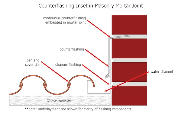
Step flashing should be installed along walls, chimneys, or gables where they intersect with roofs. Step flashing is L-shaped metal flashing that is installed along the seam where the roof meets the wall. It comes in various sizes (5x7 and 4x8 inch are common) and is installed shingle-like along level or sloped junctures with upper pieces overlapping lower pieces to direct water out of seams and wall assemblies. It should be installed under, not over, the adjacent siding (Figures 11-14). It should be installed first before laying down roofing, house wrap, and siding. The lowest course of siding should not rest on the horizontal part of the step flashing but should be attached to the wall starting an inch or so above it so that water drains off the siding and into the step flashing and then drains down to the gutter. This inch or so of metal step flashing should be visible beneath the bottom course of siding just above the abutting roof (Figures 15 and 16). Step flashing is also used, along with sloped cricket flashing around and above chimneys (Figures 17 and 18). Tile roofs use a different kind of step flashing that forms a channel along the base of the intersecting wall to hold the curved tiles in place (Figure 19). 
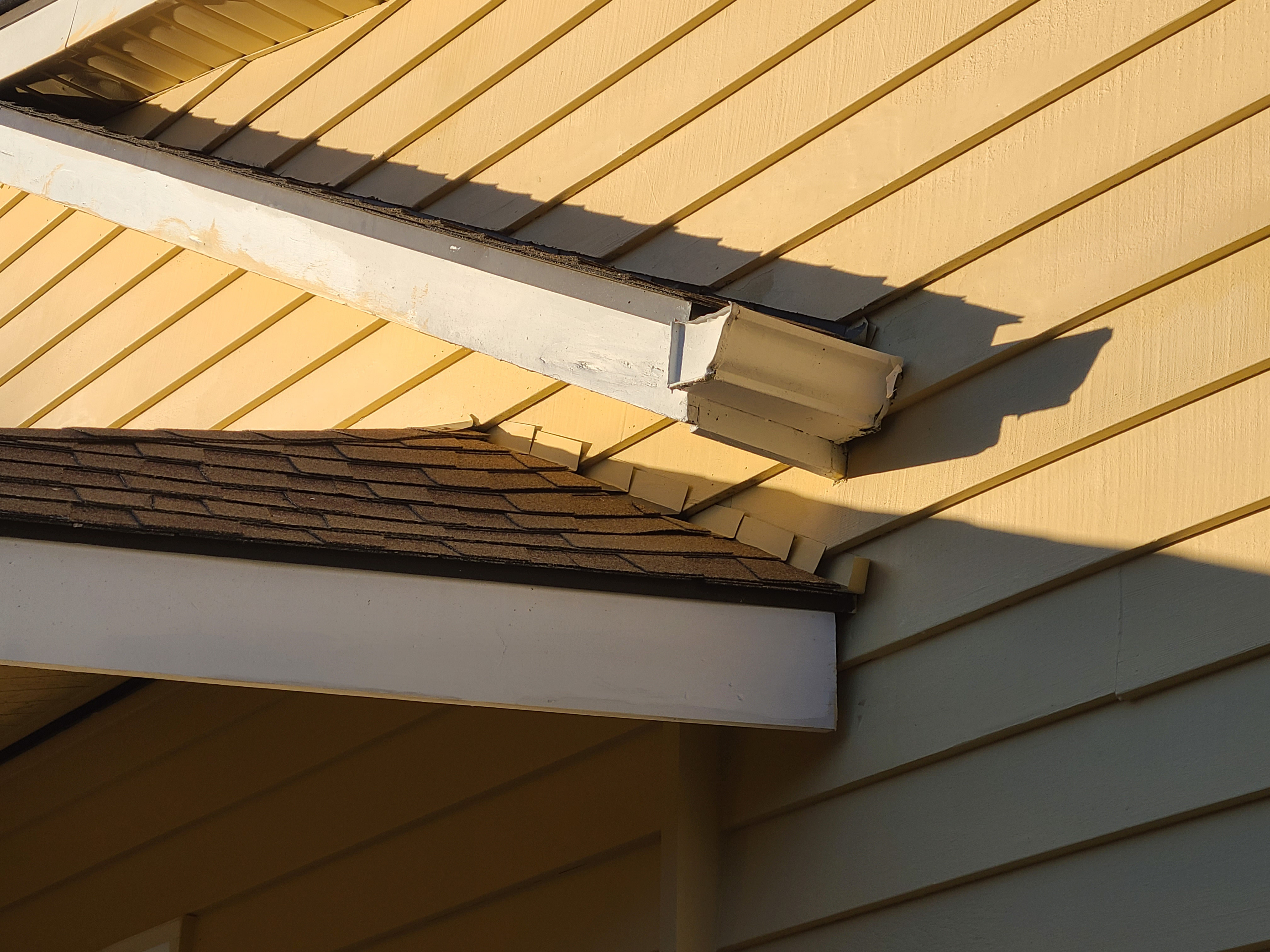
Figure 11. Flashing was done incorrectly here; the step flashing should be under the siding, there is no gutter on the lower roof, a downspout is missing, and the kickout flashing is far too small to be effective at directing water away from the wall (Source: PNNL).
Figure 12. This step flashing was installed over, not under, the siding, so water is getting behind the step flashing and rotting the siding. Also the house was badly designed with a window frame that touches the intersecting roof, inviting interior water damage (Source: PNNL).
Improper flashing can allow rain water into walls, causing significant damage
Source
Figure 13. Lack of adequate kick-out flashing led to water intrusion and rapid rotting of the OSB wall sheathing on this fairly new house (Source: DryFlekt, Inc.).
Figure 14. The metal flashing used at this wall-to-roof transition is incorrectly layered over, not under, the siding, and is nailed into the siding, creating holes where water can infiltrate the wall (Source: PNNL).
Roof-wall flashing details.
Source
Author(s)
Federal Emergency Management Agency
Organization(s)
FEMA
Description

Report containing 37 fact sheets that provide technical guidance and recommendations concerning the construction of coastal residential buildings.
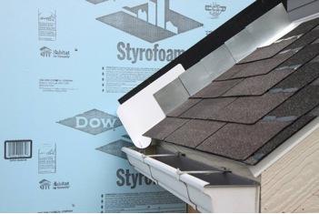
Figure 15. This roof-to-wall flashing detail shows the lower leg of the step flashing alternating with the roof tile (Source: FEMA).
Step and kickout flashing should be installed at all roof-wall intersections to protect the wall and divert rainwater runoff into a gutter.
Source
Author(s)
Baechler Michael C,
et al.
Organization(s)
Pacific Northwest National Laboratory,
PNNL,
Oak Ridge National Laboratory,
ORNL,
U.S. Department of Energy,
DOE
Description

Report providing builders in marine climates with guidance for building homes that have whole-house energy savings of 40% over the Building America benchmark with no added overall costs for consumers.
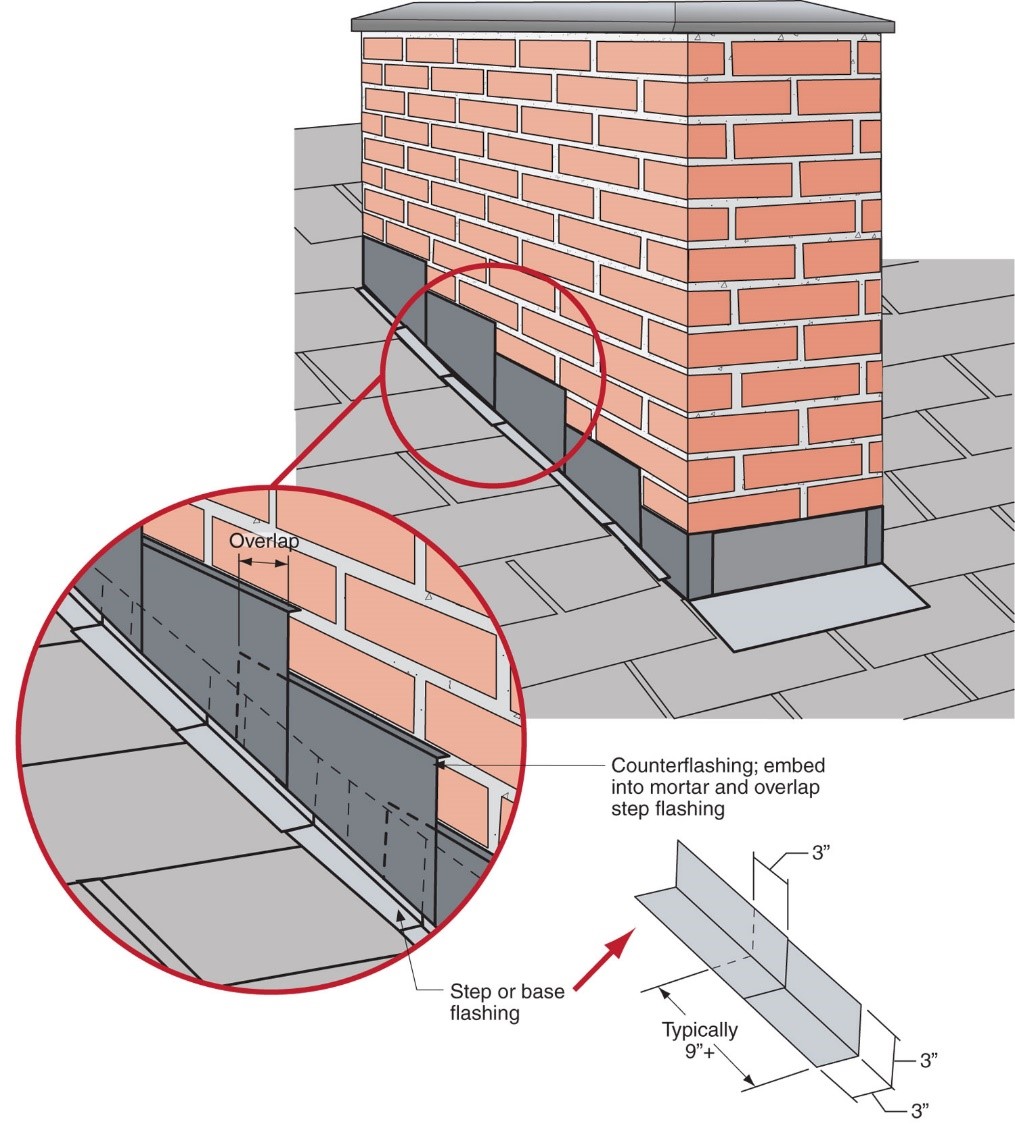
Figure 16. This step flashing is correctly installed in an overlapping fashion; the L-shaped step flashing is installed over a layer of flexible flashing and under the house wrap and siding (Source: Dryflekt, Inc.).
Right - Step flashing along a chimney is integrated in a layered manner with asphalt shingle roofing and topped with counterflashing that is embedded into brick mortar joint above
Source
Courtesy Of
BSC
Figure 17. Step flashing is correctly integrated in a shingle-layered manner with the asphalt shingle roofing, with counterflashing at the top that is embedded into the brick-and-mortar joints above (Source: Building Science Corporation).
Right – A chimney cricket is installed and flashed to direct rainwater around the chimney.
Source
Courtesy Of
BSC
Figure 18. This chimney cricket guides water around the chimney so it can drain to either side and off the roof (Source: Building Science Corporation and PNNL).
Figure 19. Clay roofs require a J-channel instead of typical L-shaped step flashing (Source: NACHI).


4. Roofs: Look for drip edge flashing.

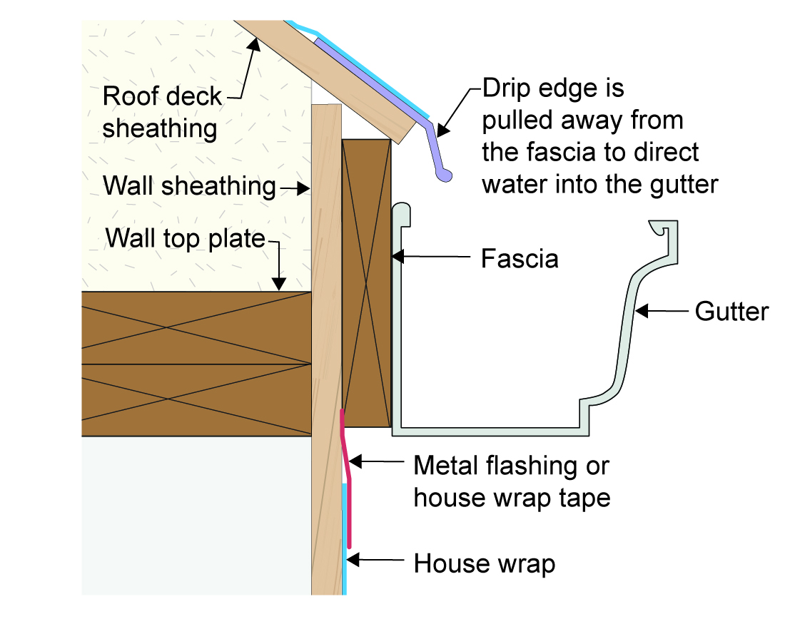
Drip edge is a typically L-shaped metal flashing installed along the edge of your roof between the roofing and the fascia (Figure 20). It helps prevent rainwater, as well as bugs, wind, and wind-blown wildfire embers, from getting into the crevice between the roofing and the fascia board, where they could cause undetected damage (Figure 21). The upper “leg” of the flashing extends 2 inches up from the roof deck, over ice-and-water shield but usually under the underlayment and roofing shingles. The lower leg extends down at least 1.5 inches over the top of the fascia board. The lower leg should not touch the fascia but should be set out from it a half-inch or so and the bottom edge of the lower leg should be flared out from the house to discourage water drops from wicking back behind the drip edge into the wood of the fascia board (Figure 22). If there is a gutter along the roof edge, the front leg of the drip edge should come down into it, not behind it, to direct water into the gutter (Figure 23). 

Figure 20. The steel drip edge flashing is easy to see above the fascia and just below the roofing along all of the roof edges of this home (Source: PNNL).
Installation of the Self-Sealing Bituminous Membrane in Relation to the Drip Edge and Roof Underlayment
Source
Author(s)
U.S. Environmental Protection Agency
Organization(s)
EPA
Description

Website providing the technical specifications and related documents for home builders, subcontractors, architects, and other housing professionals interested in certifying a home to the EPA's Indoor airPLUS program requirements.

Figure 21. Metal drip edge (shown in red) is installed along the edges of the roof to prevent rain, wind, bugs, and wildfire embers from getting into the crevice between the roofing material and the top of the fascia board (Source: U.S. EPA).
Figure 22. Don’t install drip edge flashing with the lower leg touching the fascia; this can encourage wicking of water behind the flashing. Instead set the lower leg of the drip edge away from the fascia (Source: PNNL).
Figure 23. When correctly installed, drip edge flashing directs rainwater into the gutter (Source: PNNL).

5. Roofs: Look for valley flashing.

Most building codes now require roofs to have self-adhered bituminous membrane (“peel-and-stick”) installed in the valleys and along the edges of the roof under the roof underlayment and roofing (Figure 24). For more protection, metal valley flashing can be installed in the valleys, on top of the membrane and roof underlayment and under the roofing. If your roof doesn’t have valley flashing, you can add it next time you reroof. Metal roof valley flashing comes in a 24-inch-wide metal product, shaped like a wide, flattened “W” where the center point provides a small ridge down the center of the valley flashing. A few inches of metal valley is exposed on either side of this center ridge (Figure 25). This “open valley” metal flashing will easily allow rain to wash away leaves and debris even on lower slope roofs. 
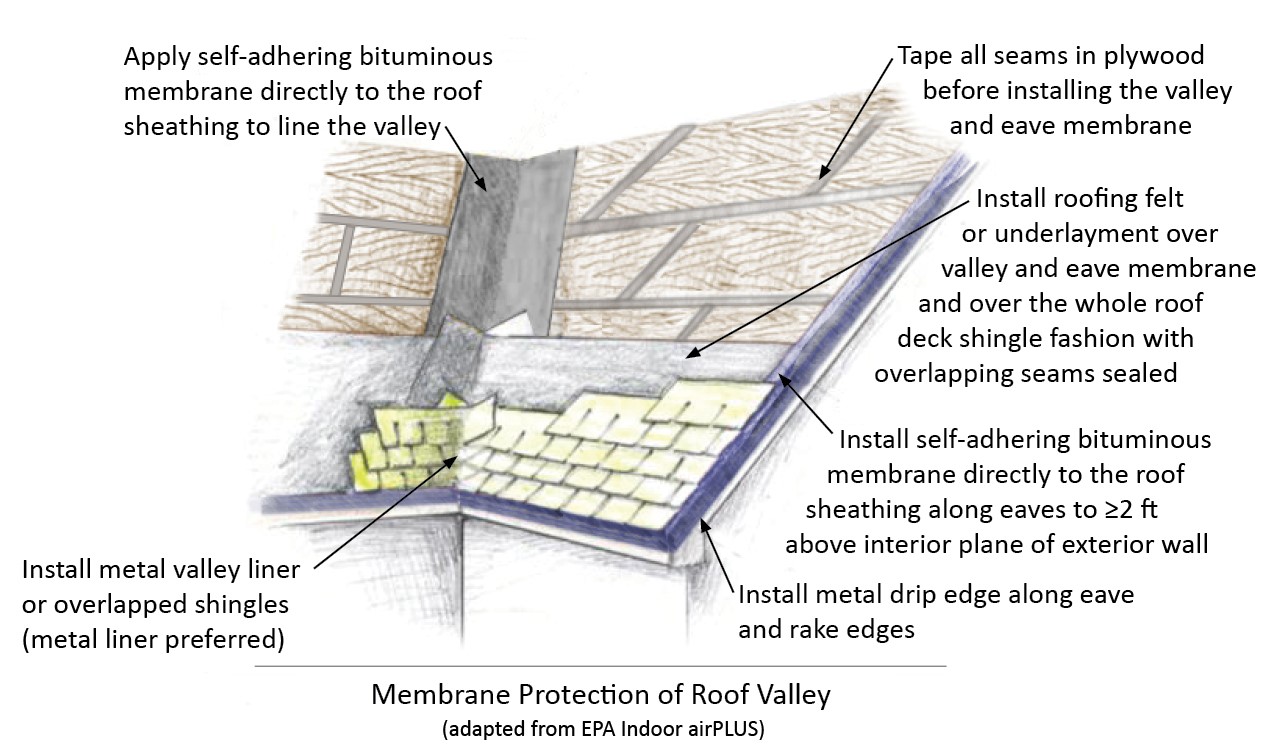
Roof valley membrane protection
Source
Author(s)
U.S. Environmental Protection Agency
Organization(s)
EPA
Description

Website providing the technical specifications and related documents for home builders, subcontractors, architects, and other housing professionals interested in certifying a home to the EPA's Indoor airPLUS program requirements.
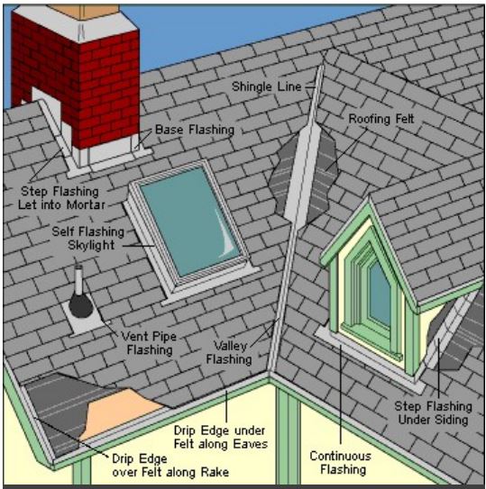
Figure 24. Self-adhering bituminous membrane is installed in the valleys and along the eaves of the roof (Source: U.S. EPA).
Right – Flashing is installed around chimney, skylight, vents, dormers, in valleys and at eaves
Source
Figure 25. This drawing shows metal valley flashing and other roof flashing details installed (Source: Home Innovation Research Labs).

6. Roof: Look at roof penetrations.

Pipes, plumbing stacks, flues, and vents through the roof should be properly flashed with boot or collar flashing. Figures 26 and 27 show pre-made boot flashing and flashing made in the field with layers of peel-and-stick membrane. The important thing is that the flashing overlaps and integrates with the roofing shingles as if it were a shingle itself. 

All exhaust fan vents and roof ventilation “mushroom” vents should also be properly flashed. Many are designed with a flashing flange around the base of the vent box that is integrated into the roofing when it is installed so that it fits under the shingles above and over the shingles below. If vents were added after the roof was installed and rely solely on caulk for waterproofing, look at the caulk or roofing sealant regularly (every two years or so) and add more as needed. Re-roofing is a great time to get rid of all the mushroom vents for a vented attic and put in continuous ridge vents. You can also put in continuous above-the-eave vents and switch to unvented soffits for greater resilience against wind-borne fire embers and rain.
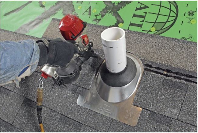
Right – Integrate pipe flashing with roof shingles
Source
Figure 26. Integrate pipe flashing with roof shingles so that water will roll from the upper row to the next row (Source: Home Innovation Research Labs).
Sealing direct roof penetrations—final steps
Source
Author(s)
U.S. Environmental Protection Agency
Organization(s)
EPA
Description

Website providing the technical specifications and related documents for home builders, subcontractors, architects, and other housing professionals interested in certifying a home to the EPA's Indoor airPLUS program requirements.

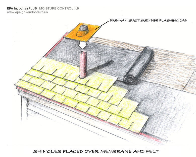
Figure 27. You can seal around piping and other roof penetrations with self-sealing bituminous membrane that is layered shingle-fashion with the roof underlayment (Source: U.S. EPA).

7. Walls: Examine siding.

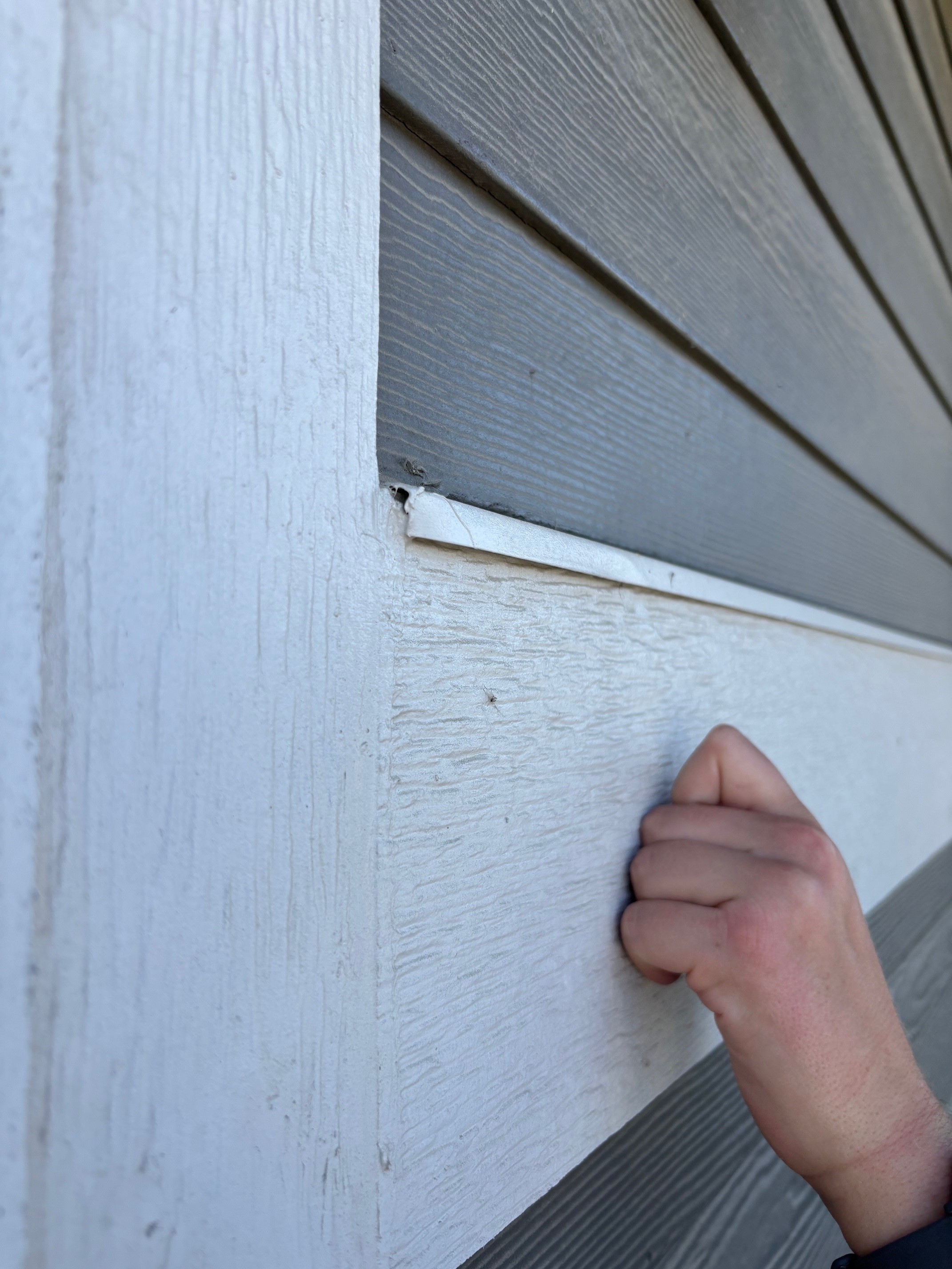
Examine siding, especially near gutters, penetrations, windows, and doors; look for discoloration, bubbling paint, or soft or deteriorating siding or trim (Figures 28 and 29). To check wood quality, take a screwdriver or your thumb nail and push into the wood siding or trim anywhere you see peeling or discoloration. The wood should be firm. If there is any squishiness or sponginess, then further investigation is needed - the wood is getting water damaged. Work with an experienced contractor to determine and resolve the cause of this water issue. Some obvious causes are missing gutters and rain splash-back against the house, sprinklers misdirected toward the house, siding that touches the ground, yards that slope toward the house, or planter boxes against the house (Figure 30). In the next steps, we’ll talk about missing flashing.
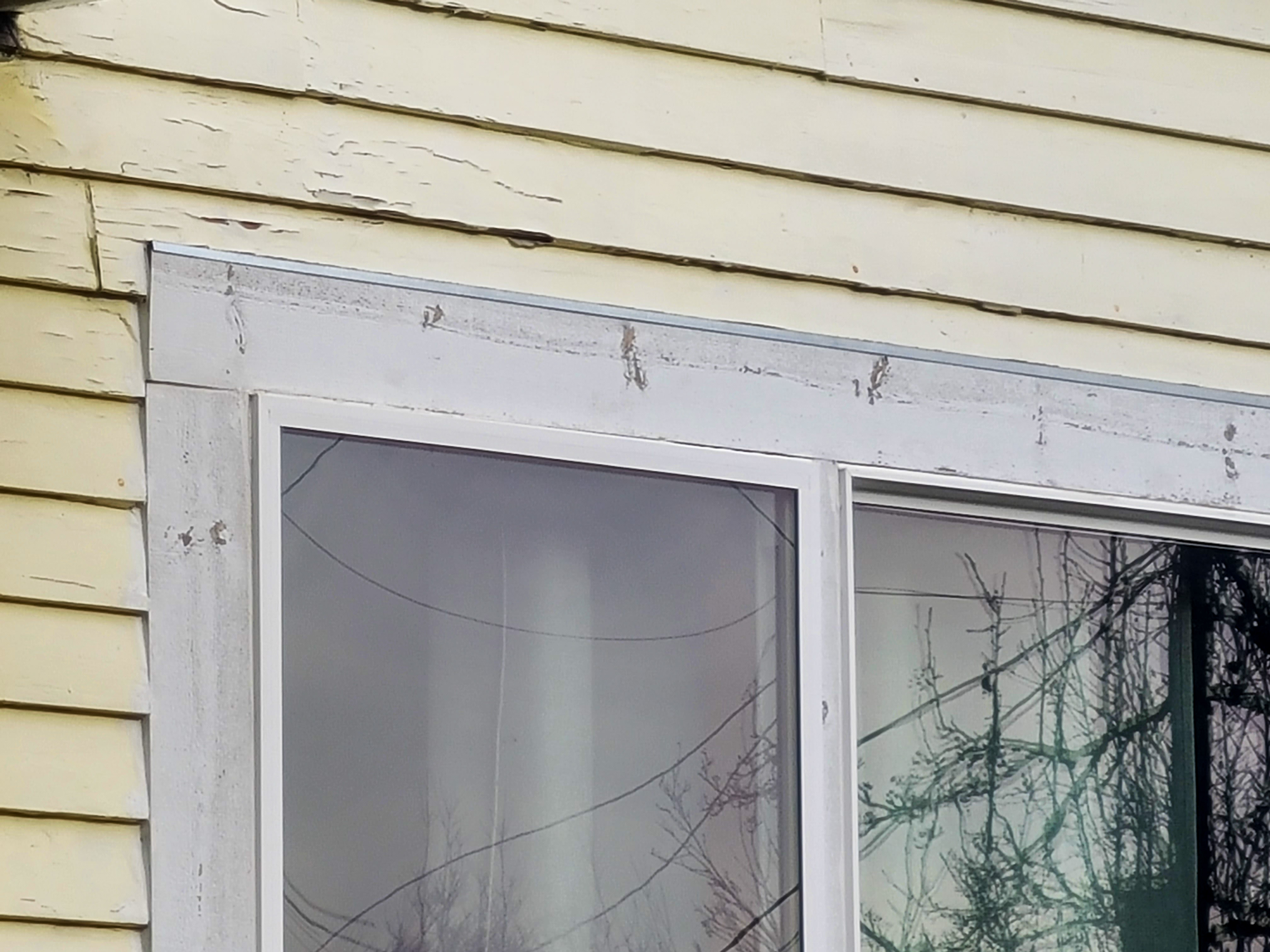
Figure 28. Peeling paint and warping siding above this window are indicative of moisture and should be investigated (Source: PNNL).
Figure 29. Discoloration and peeling paint means there could be a moisture issue that should be addressed (Source: PNNL).
Figure 30. Ensure that planter boxes have a water-proof backing that separates them from the wall to prevent moisture damage and water intrusion into the wall behind them (Source: PNNL).

8. Walls: Look for flashing at wall openings and transitions.

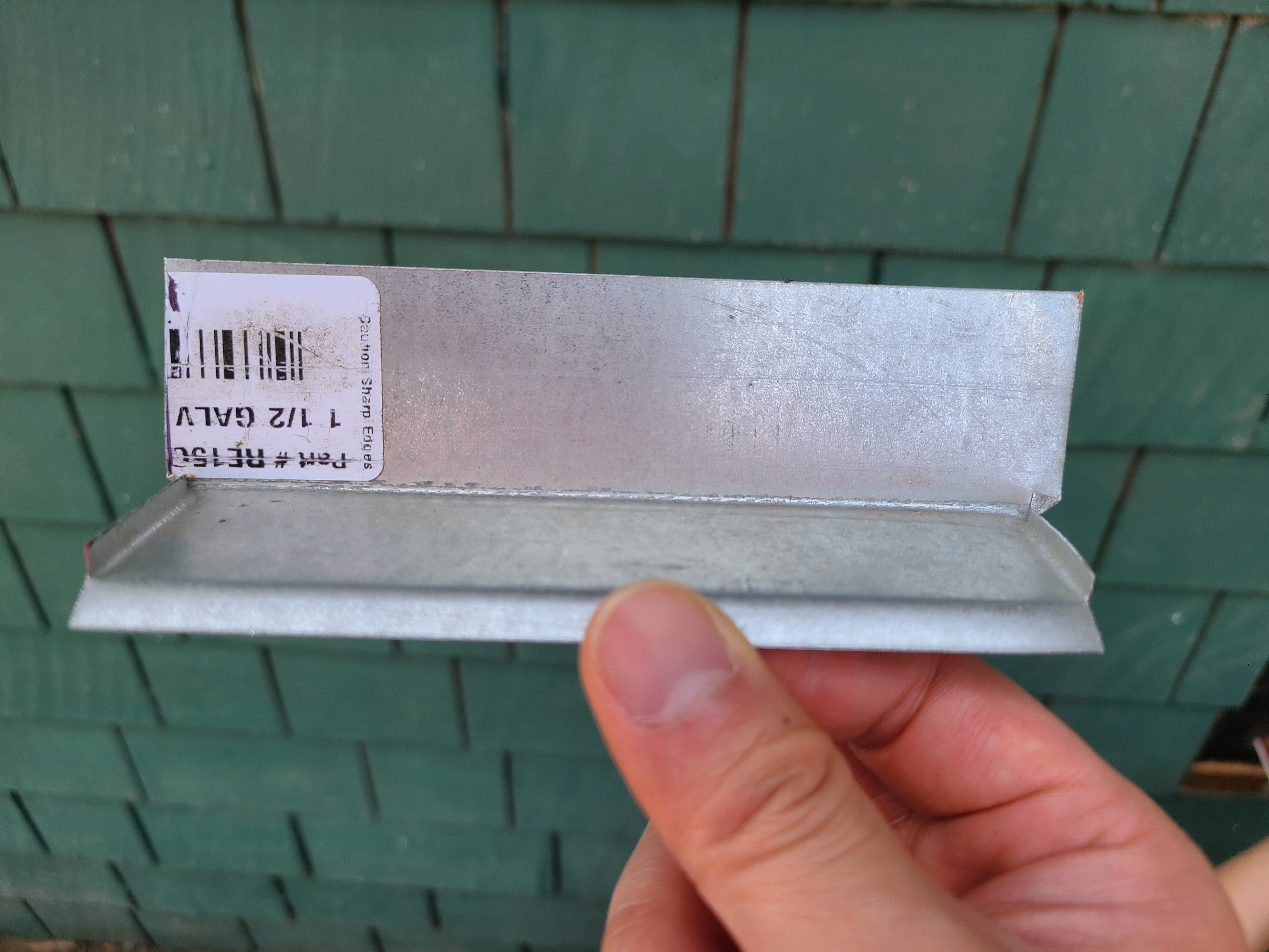
Examine the walls and look for flashing above doors, windows, water faucets, lights, and siding transitions. It’s hard to see flashing tape and house wrap without breaking into walls or removing trim, but metal drip edge head flashing should be visible over doors, windows, and trim around water spigots and vent outlets. Drip edge, metal Z flashing or metal or vinyl through-the-wall flashing should be visible at transitions between wall materials or between the above-grade walls and the foundation walls (Figure 31). Gaps around wiring or pipes that come through exterior walls should be filled in or covered with caulk, spray foam, flashing tape, or gaskets. Lack of flashing at wall transitions can be disastrous for a home (Figure 32). Figures 33-44 show examples of the types of flashing to look for.

Proper installation of flashing for drainage
Source
Author(s)
Straube John
Organization(s)
Building Science Corporation,
BSC
Description

Document covering basic moisture control principles in the design of above-grade building enclosures; driving rain as a moisture load on walls; a classification system of the various rain control strategies available for walls; and good design practises for walls.

Figure 31. This drawing depicts several types of flashing to direct water out of wall assemblies (Source: Building Science Corporation).

Figure 32 shows what can happen when there is no through-the-wall flashing between the lap siding and the stone wall to direct water out. Rainwater sat on the capstone and wicked into the wall, then ran down the wall behind the stone, was absorbed by the sheathing, and then rotted out the framing and the sheathing at the base of the wall. Another problem here is that the highly porous artificial stone comes all the way down the wall into the ground. This ground contract provides a constant source of moisture that wicks into the wall – there should be an 8-inch gap of water-proofed foundation wall between the soil and the stone.

Figure 32. The rotting wood in this wall is the direct result of missing flashing between the lap siding and the stone wall. Rainwater landed on the unsloped capstone and wicked into the wall, then rotted out the framing and sheathing. The lack of a gap between the porous artificial stone and the ground contributed to water wicking. (Source: Steve Easley & Associates).
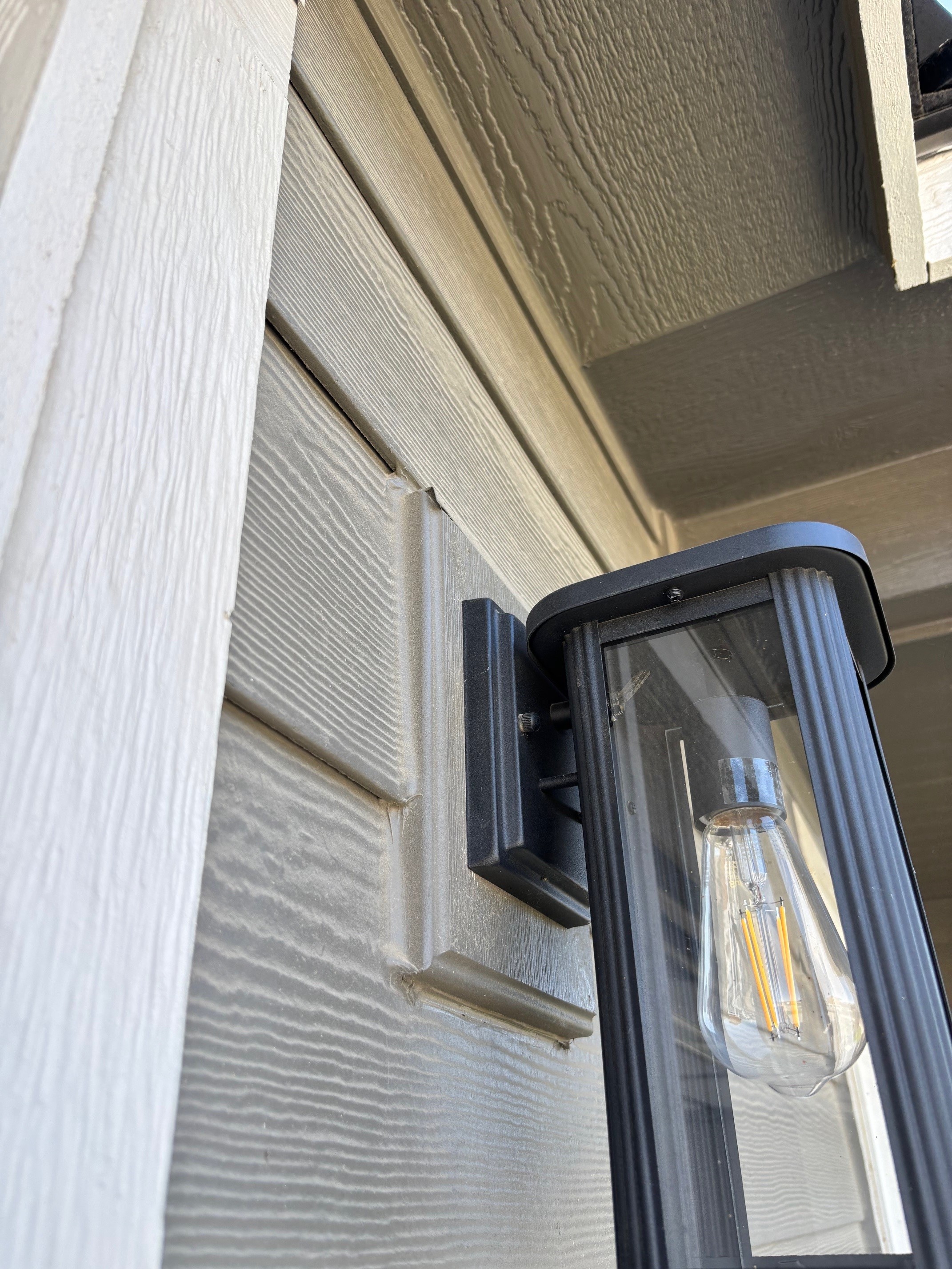
Figure 33. Cap flashing can be installed over smaller penetrations like outlets and lights to prevent water intrusion (Source: PNNL).
Figure 34. This porch light has cap flashing to direct water out and over the wood trim; the drip edge on the metal flashing could protrude out further (Source: PNNL).
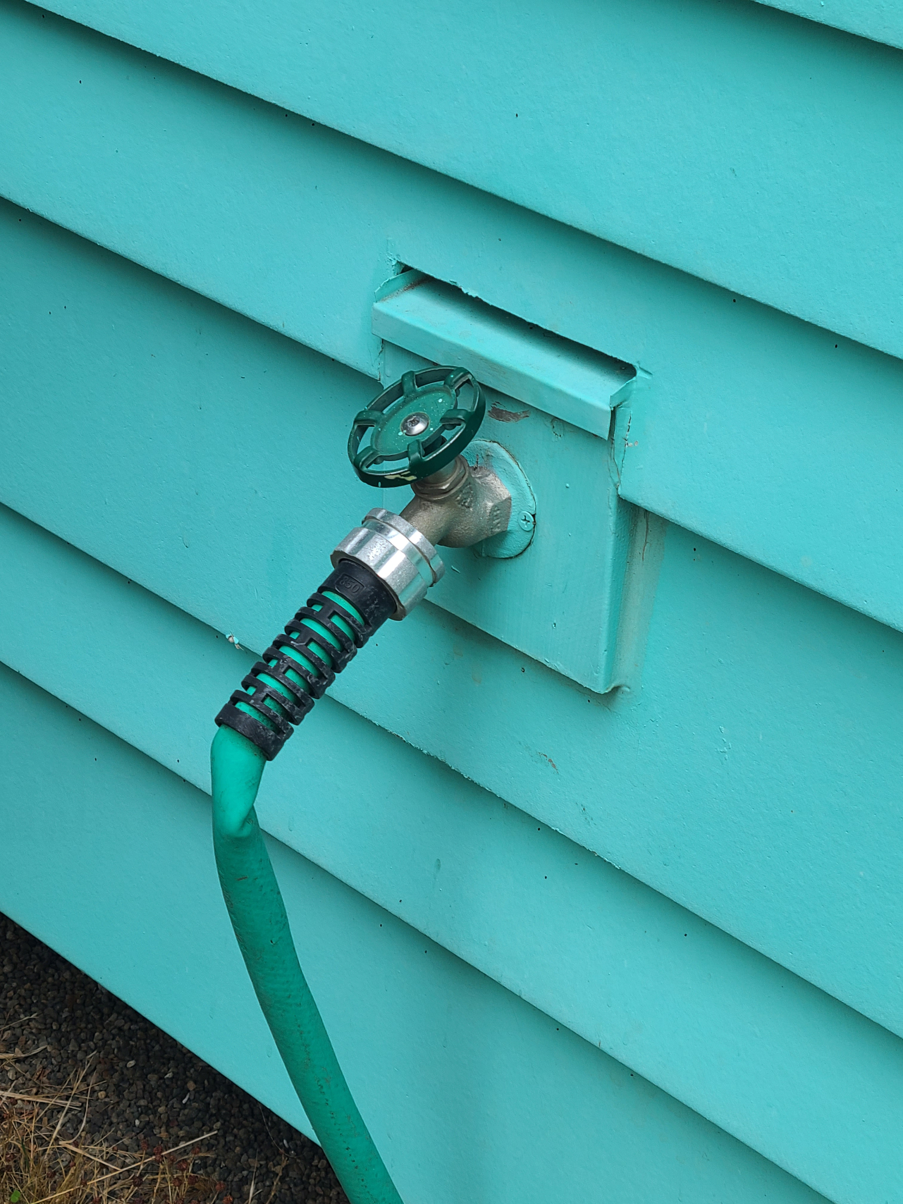
Figure 35. This hose bib has head flashing (Source: PNNL).
Right - Peel and stick flashing and flashing tape seal a plumbing pipe that penetrates an exterior wall.
Source
Figure 36. A self-adhered gasket, flashing tape, and spray foam provide the first layers of air and water sealing around this plumbing penetration through the foundation wall (Source: Sareth Builders).
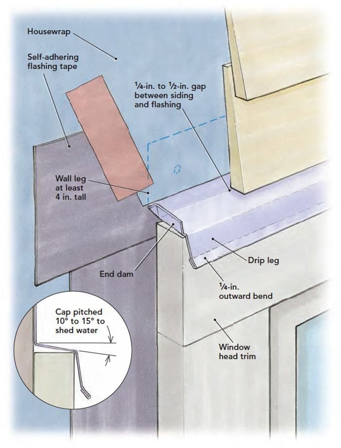
Figure 37. This detail shows proper installation of head flashing over a window (Source: Fine Homebuilding).
Figure 38. This through-the-wall flashing direct water out of the wall at this siding transition (Source: PNNL).
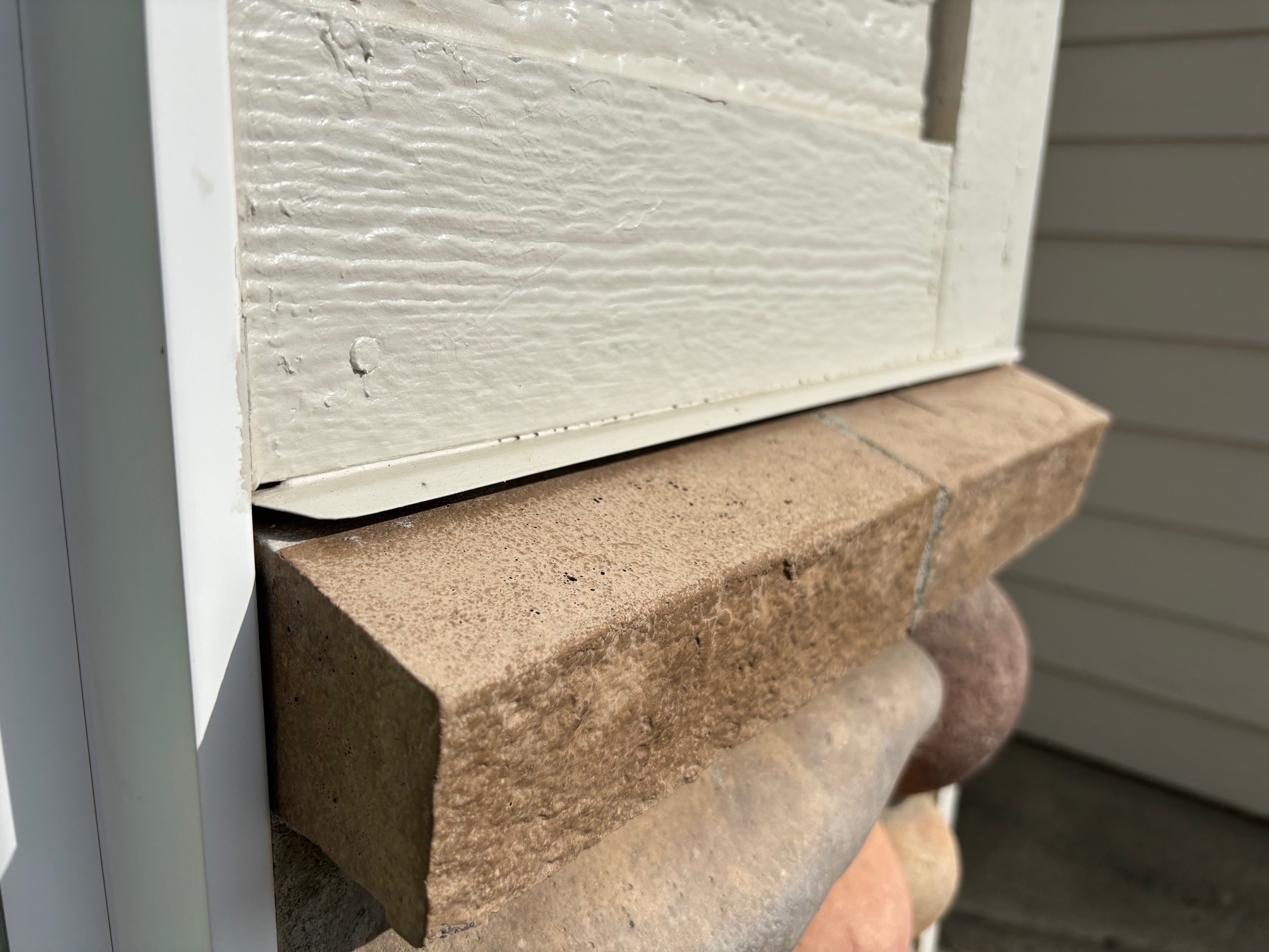
Figure 39. This through-the-wall flashing directs any water that get into the wall through the lap siding out at the transition to the stone cladding which has a capstone that is properly sloped away from the wall (Source: PNNL).
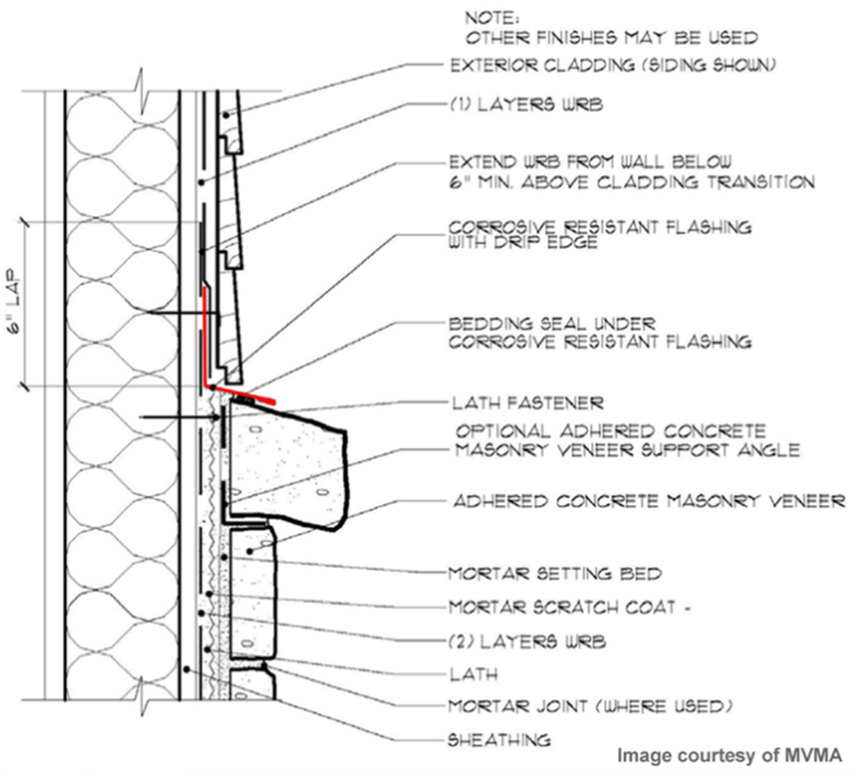
Figure 40. The red piece in this detail is through-the-wall metal flashing; it is installed on the sheathing just above the capstone, with house wrap installed to lap down over it. Gaps below the house wrap and the lap siding prevent wicking of water up behind the siding (source: Masonry Veneer Manufacturers Association).
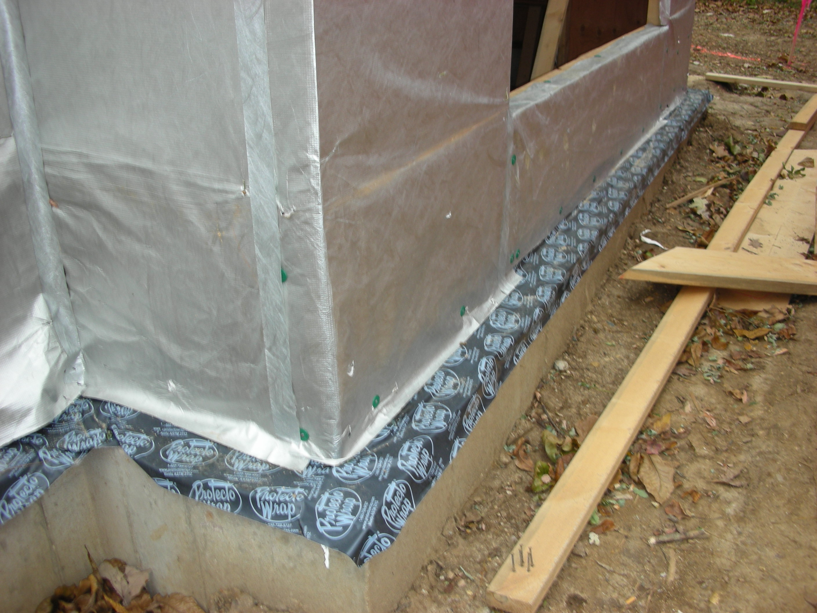
Flexible rubber through-wall flashing
Source
Figure 41. This flexible membrane flashing provides a capillary break between the concrete foundation stem wall and the above-grade framed wall (Source: Steve Easley & Associates).
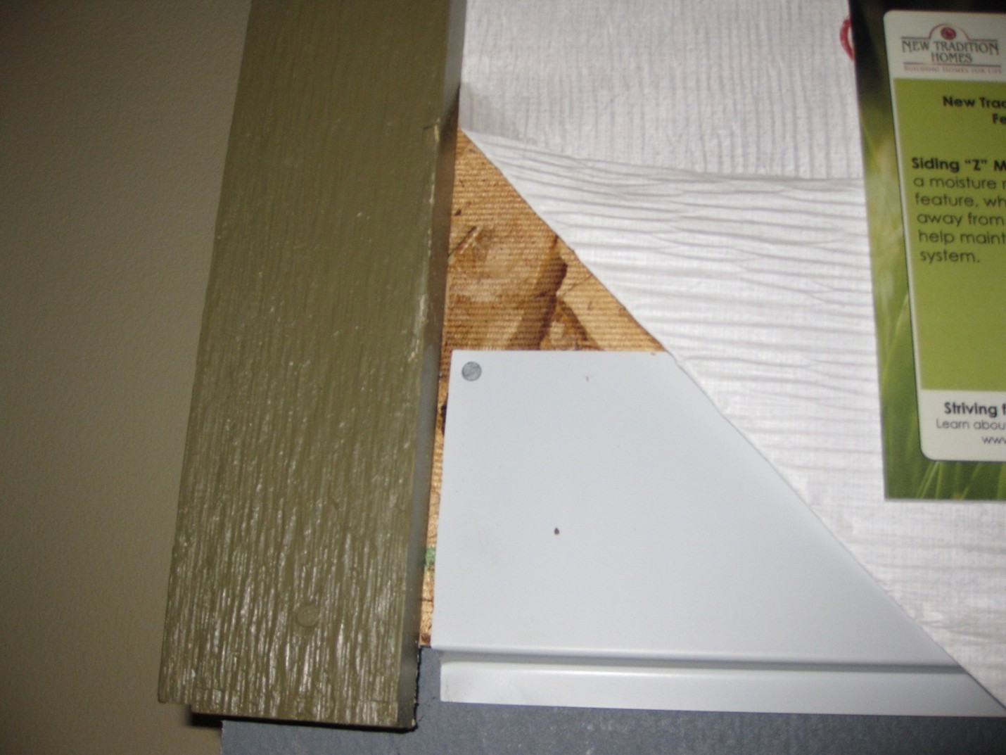
Figure 42. This construction mockup shows how metal Z flashing protects the bottom edge of the OSB wall sheathing from bugs, rain splash-back, and drifting snow (Source: PNNL).
Z flashing is installed behind the rigid foam and metal lathe that goes behind the stucco siding to protect the transition between the wall sheathing and the exterior foundation insulation.
Source
Figure 43. Metal Z flashing is installed behind the rigid foam and metal lathe that goes behind the stucco siding to protect the transition between the wall sheathing and the exterior foundation insulation (Source: Mandalay Homes).
Wood/fiber cement drainable wall assembly
Source
Author(s)
U.S. Environmental Protection Agency
Organization(s)
EPA
Description

Website providing the technical specifications and related documents for home builders, subcontractors, architects, and other housing professionals interested in certifying a home to the EPA's Indoor airPLUS program requirements.

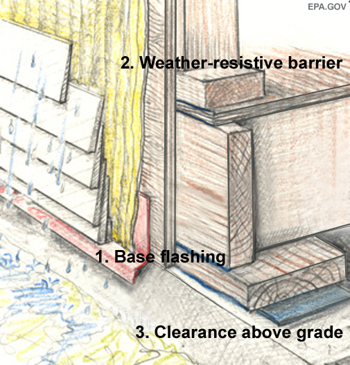
Figure 44. Proper installation of flashing at the wall-foundation transition directs water away from the sill plate and out of the wall and (Source: U.S. EPA).


9. Wall: Look for deck flashing.

Decks deserve special attention because poor drainage and flashing details at the deck-to-house interface can lead to extensive damage of the home’s exterior walls including rotting of cladding, sheathing, and framing. Look for metal flashing over the top of the ledger board, a gap separating the deck boards from the wall and a gap of at least ¼-inch (more is better) separating the bottom of the first course of siding from the top of the first board. See Figures 45, 46, and 47 for good deck installation details. If you plan to build or renovate a deck, you or your contractor should check local code for ledger attachment and flashing requirements which have changed in recent code cycles. 
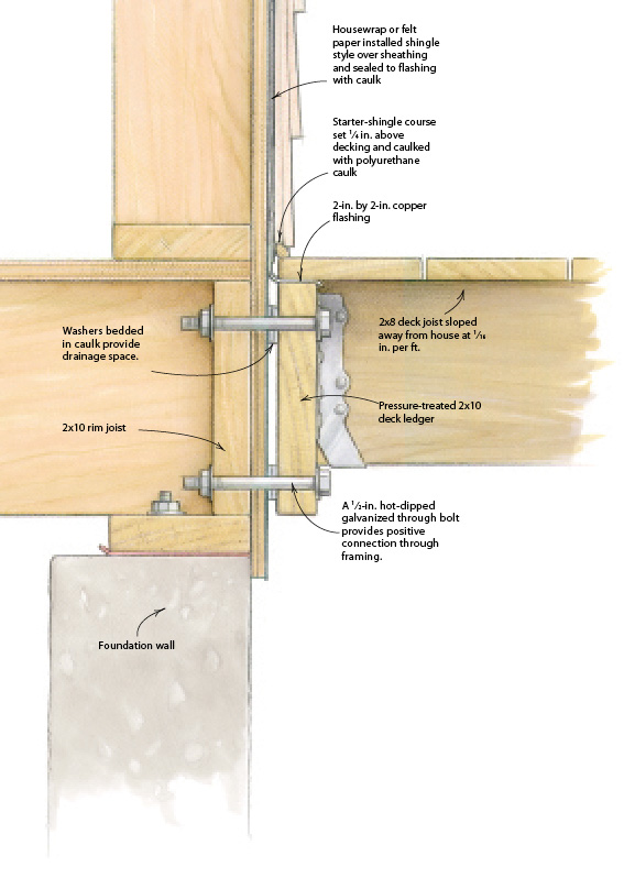
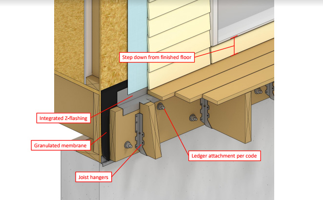
Figure 45. Flashing may tie into the porch and direct drainage under the porch, which protects the porch-wall interface from moisture; note also the washers that separate the porch and home to prevent additional wicking (Source: PNNL).
Figure 46. Metal flashing protects the top of the ledger board, and the wall behind it is protected by bituminous self-adhered or metal flashing integrated with the house wrap. Note there are gaps of at least 1/4 inch between the ledger flashing and the first deck board and the deck board and the first row of siding to provide capillary breaks (Source: IBACOS).
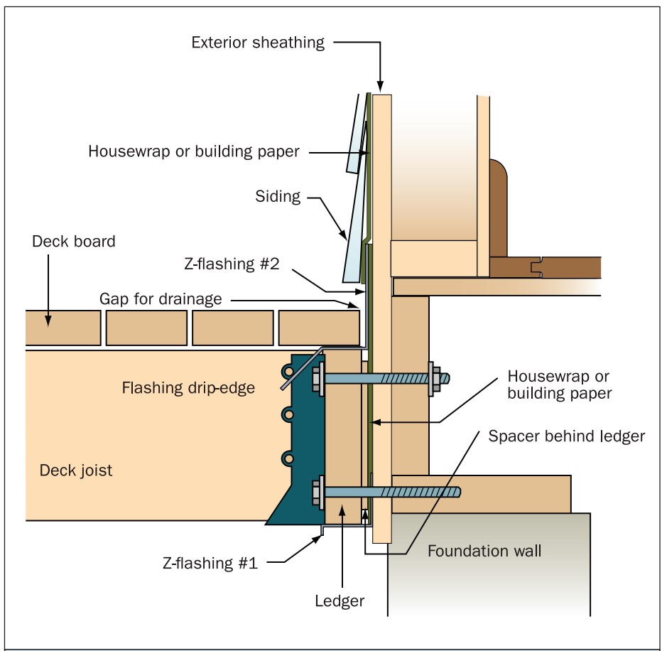
Deck ledger flashing and fastener details.
Source
Author(s)
Federal Emergency Management Agency
Organization(s)
FEMA
Description

Report containing 37 fact sheets that provide technical guidance and recommendations concerning the construction of coastal residential buildings.

Figure 47. Deck ledger flashing details showing an assembly option with spacers (Source: FEMA).

Additional Info

Last Updated

Disclaimer

This content is a work created with funding provided by the United States Department of Energy under Contract no DE-AC05-076RL01830 for the operation of Pacific Northwest National Laboratory. The information and guidance provided by Pacific Northwest National Laboratory (PNNL) in the content are intended solely for educational purposes only and do not constitute formal training or certification. It is provided with the explicit understanding that neither the United States Government nor the United States Department of Energy, nor the Contractor, nor any or their employees, nor any jurisdiction or organization that has cooperated in the development of these materials, makes any warranty, express or implied, or assumes any legal liability or responsibility for the accuracy, completeness, or usefulness or any information, apparatus, product, software, or process disclosed, or represents that its use would not infringe privately owned rights. Reference herein to any specific commercial product, process, or service by trade name, trademark, manufacturer, or otherwise does not constitute or imply its endorsement, recommendation, or favoring by the United States Government or any agency thereof, or Battelle Memorial Institute. The views and opinions of authors expressed herein do not necessarily state or reflect those of the United States Government or any agency thereof. Viewers assumes full responsibility for all actions that they may take from information provided in this content including ensuring the safety, code compliance, and proper functionality of any products they choose to install. Installation and use of such products should be performed in accordance with local regulations and manufacturer instructions.