

Drawings
2021 IECC Climate Zones 7 and 8: Vented Cathedral Ceiling, 2x6 Wall, Interior Insulated Basement
Notes
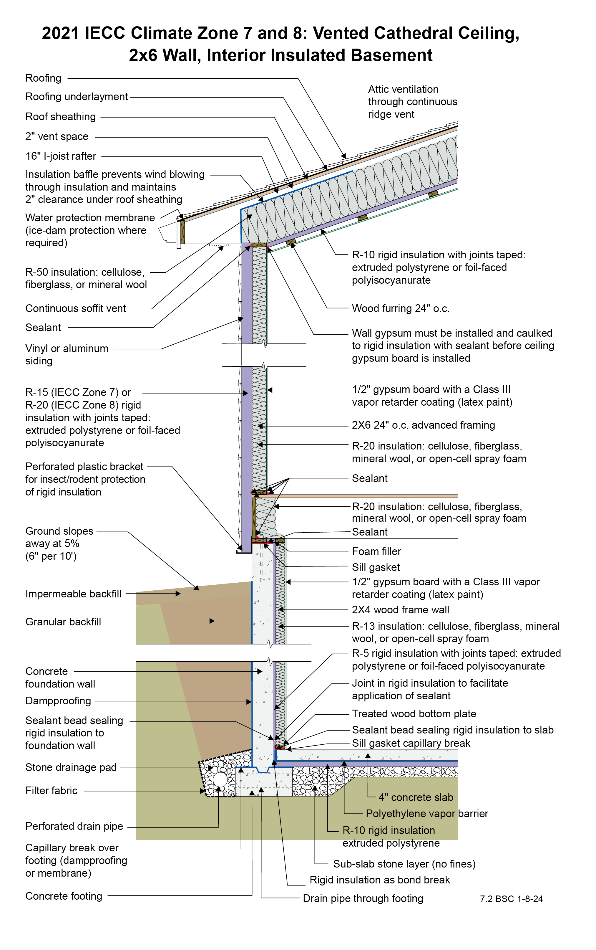
Drawing 7.2: IECC CZ 7 and 8: Vented Cathedral Ceiling, 2x6 Wall, Interior Insulated Basement
- The R-10 rigid foam at the ceiling is not required for vapor control purposes in Climate Zone 7 as long as sufficient ridge- and soffit-venting is provided. However, it will aid the control of moisture by slowing vapor transfer from the conditioned space to the roof assembly. The rigid foam brings the total roof R-value up to the 2021 IECC requirement of R-60. Because the I-joist rafter is 16 inches and a 2-inch ventilation space is needed above the insulation, only about 14 inches are available for the fibrous cavity insulation. This will typically give an R-value of about R-50, leaving the need for the R-10 rigid foam. Note that only 1 inch of ventilation space above the cavity insulation is required by code, but 2 inches is recommended in areas where ice damming could be an issue or where rafter spans are long. The rigid foam at the ceiling is also used to allow the creation of a service raceway between the rigid foam and the gypsum board below it. The rigid foam acts as the air control layer instead of the gypsum board. The service raceway allows the air control layer to be undisturbed by the electrical penetrations in the ceiling. A third purpose of the rigid foam in this application is that it also reduces drywall cracking. From a vapor control standpoint, however, the rigid foam and the raceway are not required by 2021 IRC, and R-60 fibrous cavity insulation could be installed directly on top of the gypsum board if cavity height allows and if the attic is properly ventilated. In this case the gypsum board would become the air control layer and would need to be carefully sealed, and a Class I or II vapor retarder paint would be recommended at the ceiling.
- A low-permeance roofing underlayment (less than 1 perm) is recommended for this roof type in this climate to reduce water diffusion through the underlayment to the sheathing.
- The wall is framed with 2x6 24” o.c. advanced framing as it uses less board footage (volume of wood framing) than standard 2x4 16” o.c. framing and has therefore been shown to be less expensive in material cost. It has also been proven to be less expensive in labor (25% fewer framing members) and is faster to assemble. This must be balanced with the difference in insulation costs for the two framing approaches.
- The R-15 or R-20 rigid insulation on the exterior of the wall framing is required by 2021 IRC Table 702.7(3) to control condensation within the framing cavities. There is no interior vapor barrier on the interior surface of the wall – there is a vapor “retarder” (Class III vapor retarder – semi-permeable latex paint). The reason that there is no interior vapor barrier is to permit drying to the interior.
- For Climate Zone 8, this assembly does not require any cavity insulation per 2021 IECC due to the R-20 continuous rigid foam. However, filling the cavity may be needed or preferred for fire protection, acoustics, and energy efficiency.
- An alternative to this wall assembly that meets both thermal and vapor control code requirements is to use an R-13 2x4 wall with R-10 (climate zone 7) or R-12.5 (climate zone 8) rigid foam on the outside.
- The rigid foam on the exterior of the wall allows construction without using structural sheathing: alternative methods of wall bracing are used instead, and the rigid foam provides a backstop for the cavity insulation as well as some structural support to the siding. Many contractors have found this to be a more economical approach.
- The R-5 rigid insulation on the interior of the concrete foundation wall is required to control condensation within the interior frame wall as there is no interior vapor barrier on the interior of the frame wall – there is a Class III vapor “retarder” (semi-permeable latex paint). The reason that there is no interior vapor barrier on the interior of the frame wall is to permit drying to the interior. Additionally, the R-5 rigid insulation on the interior of the concrete foundation wall reduces the rate at which moisture contained in newly placed concrete moves to the interior.
- The plastic L-bracket at the bottom of the wall’s exterior rigid insulation should be perforated to facilitate drainage.
- The vertical “short” strip of rigid insulation where the basement concrete slab intersects the exterior concrete basement wall has two lines of continuous sealant. The first seals the concrete slab edge to the interior surface of the vertical strip. The second seals the top back corner of the vertical strip to the concrete foundation wall. The two seals provide air control layer continuity between the concrete slab and the concrete wall to control radon and other soil gases.
- Horizontal insulation on the underside of the concrete floor slab is provided for comfort reasons and to control dust mites in carpets by reducing the relative humidity within the carpets.