Showing results 1 - 50 of 4718
Image
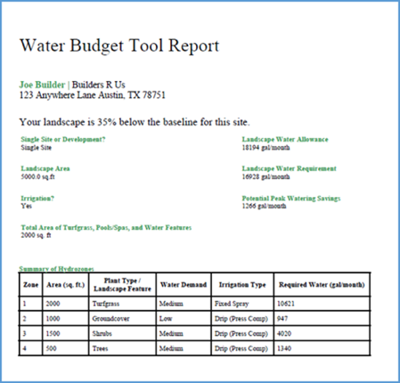
An example of the water budget tool report for determining a home's landscaping irrigation needs.
Image
Image
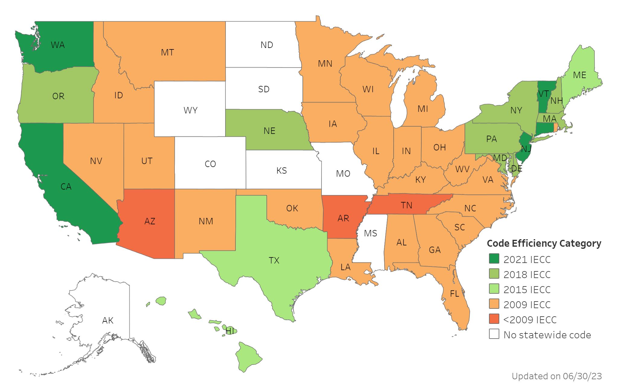
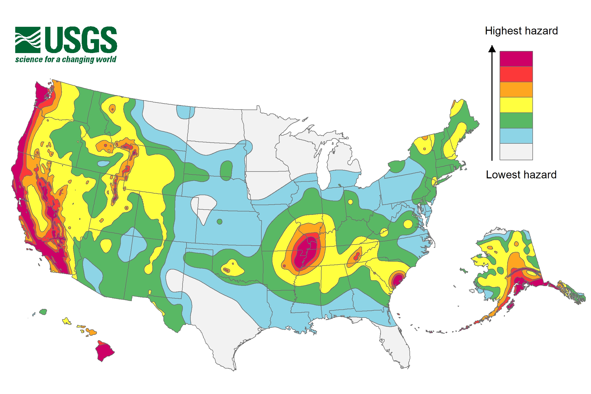
DOE's Building Energy Codes Program tracks the status of state energy code adoption and state equivalency to various versions of the International Energy Conservation Code.
Image

Image
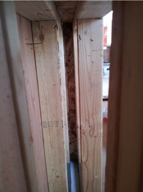
Example of the advanced framing technique, double-stud wall cavity, which will later be filled with blown insulation
Image

Image

Imery & Company built this custom for buyer home in the mixed-humid climate in Lilburn, GA, and certified it to DOE Zero Energy Ready Home specifications in 2018.
Image
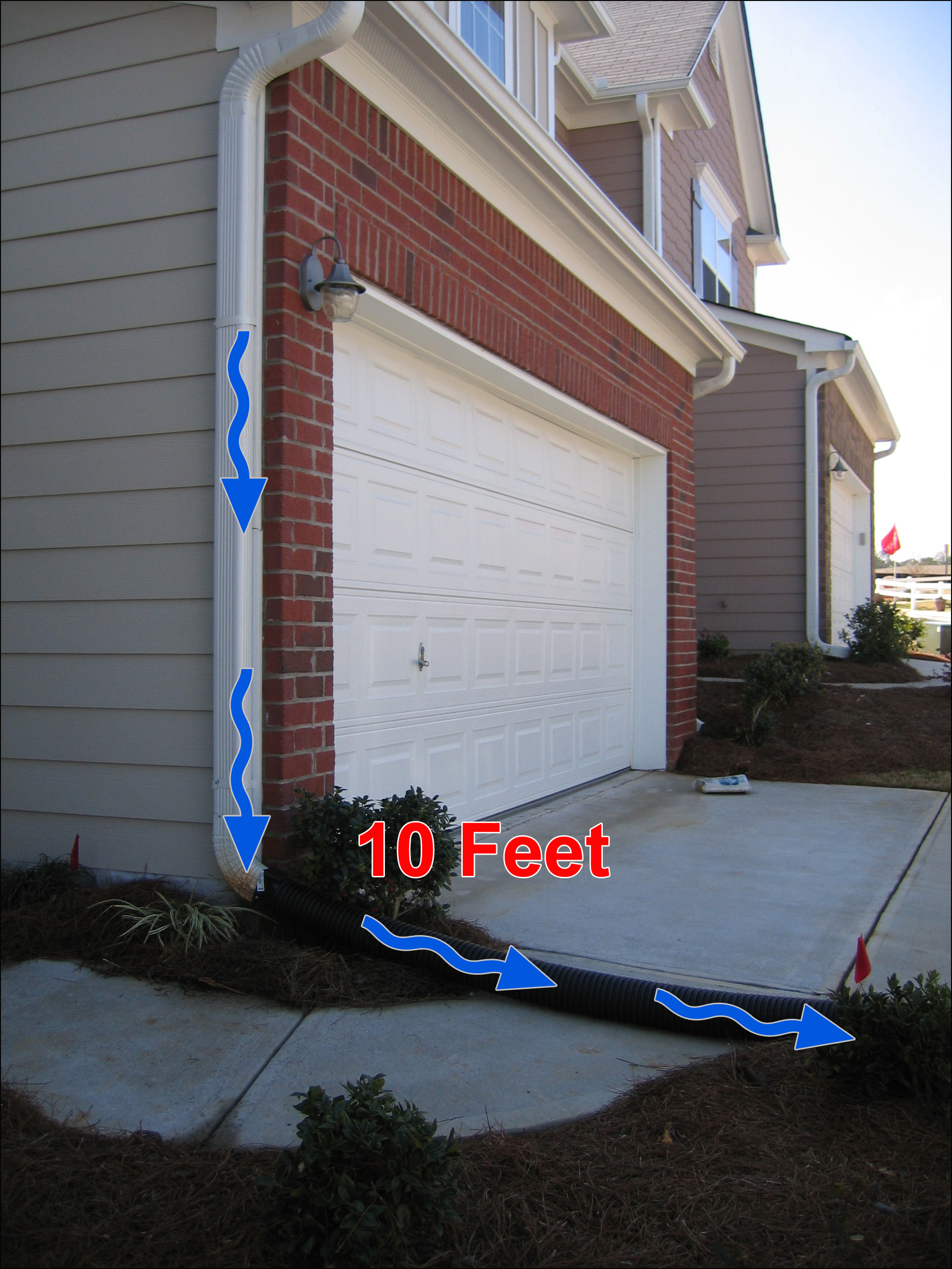
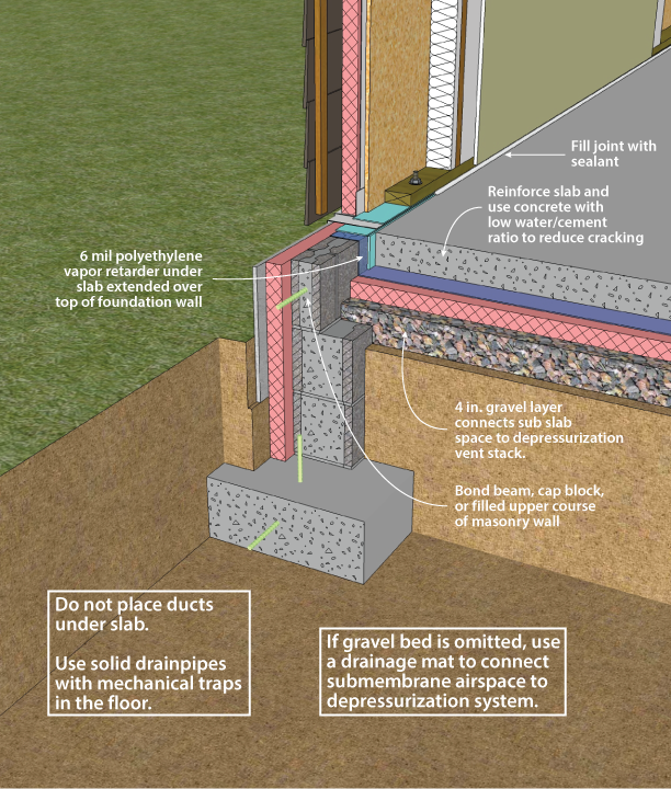
Impervious surfaces like patio slabs, sidewalks, and driveways that are within 10 feet of the home should slope away from the house.
Image
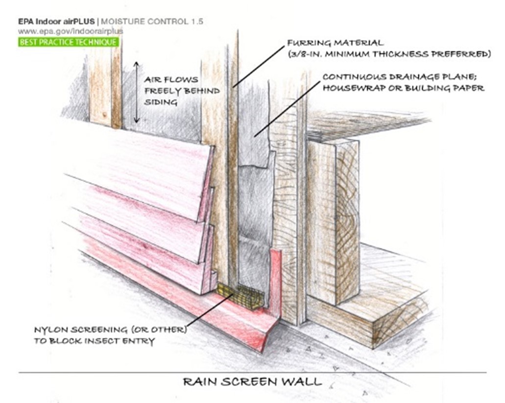
Install mesh insect barrier along the bottom of the rain screen behind the exterior cladding of above-grade walls
Image
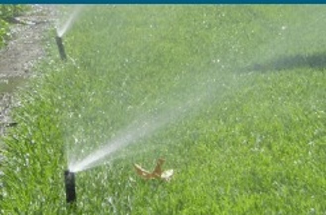
Place plants at least 18 inches from the building's walls and foundation and direct irrigation water to spray away from the structure.
Image
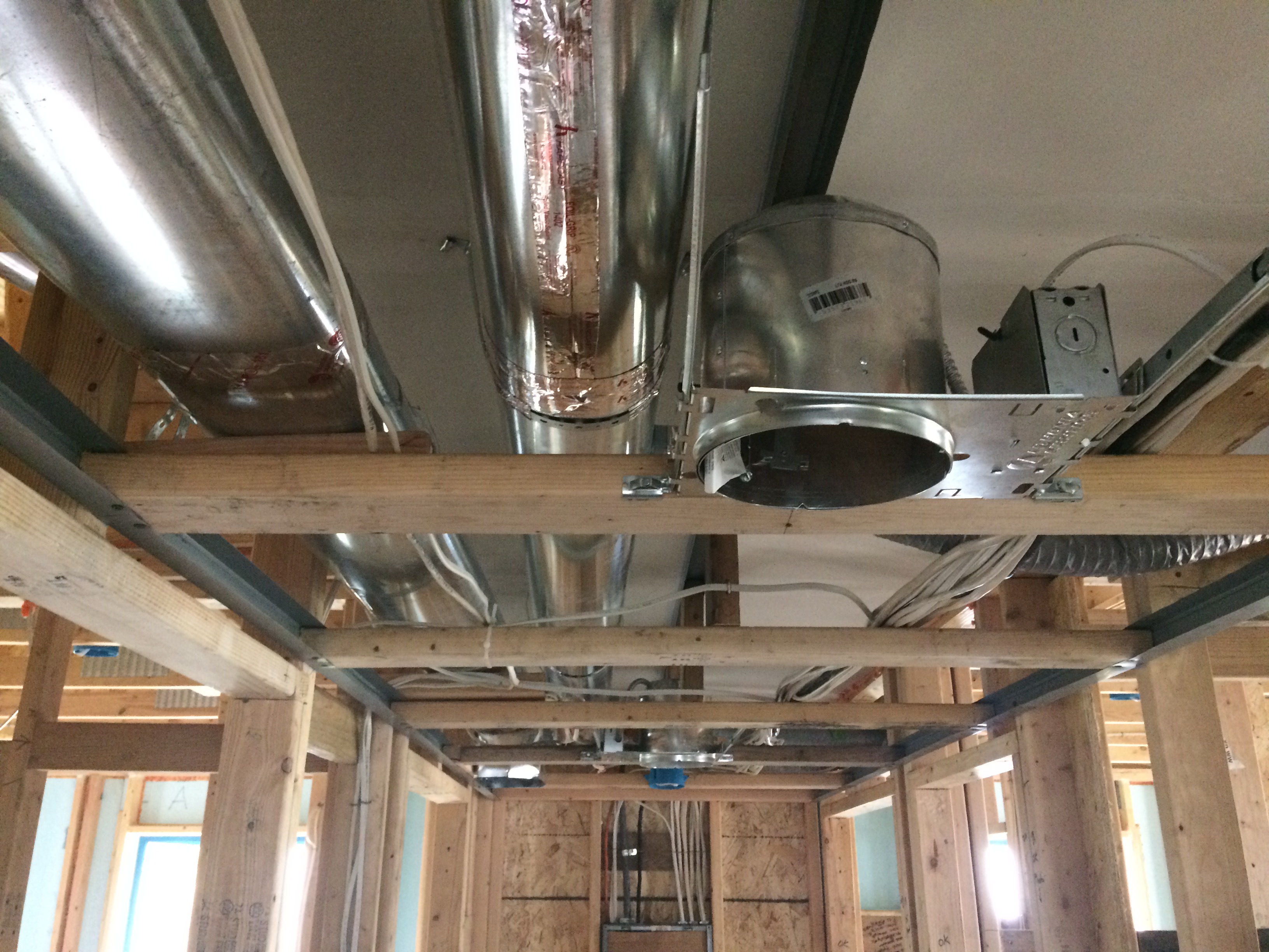
Right - Drywall is installed as an air barrier above the central hallway duct chase prior to installing the trunk ducts.
Image
Image
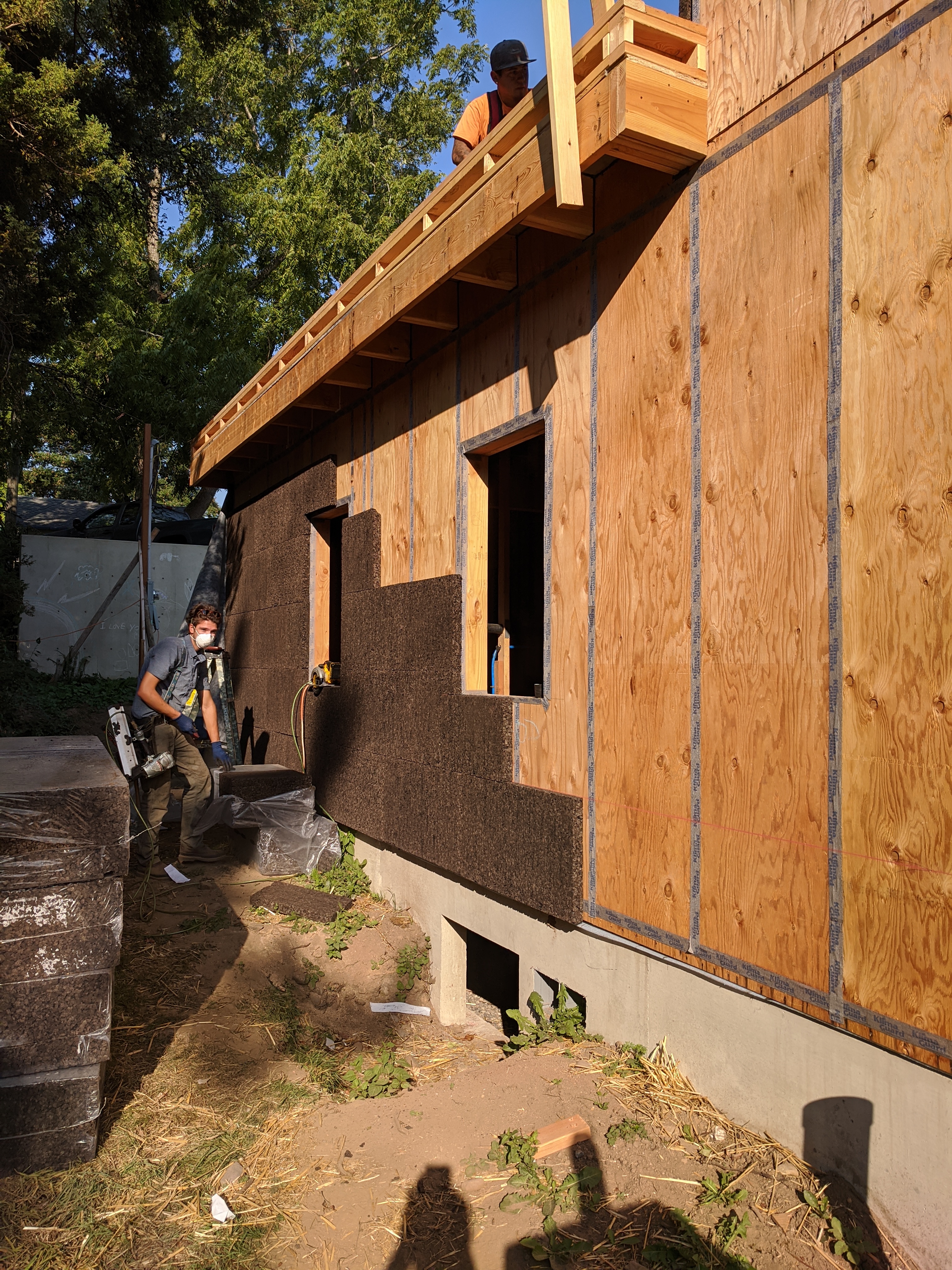
Taped plywood provides an air barrier beneath the cork insulation installed on the exterior of this home.
Image
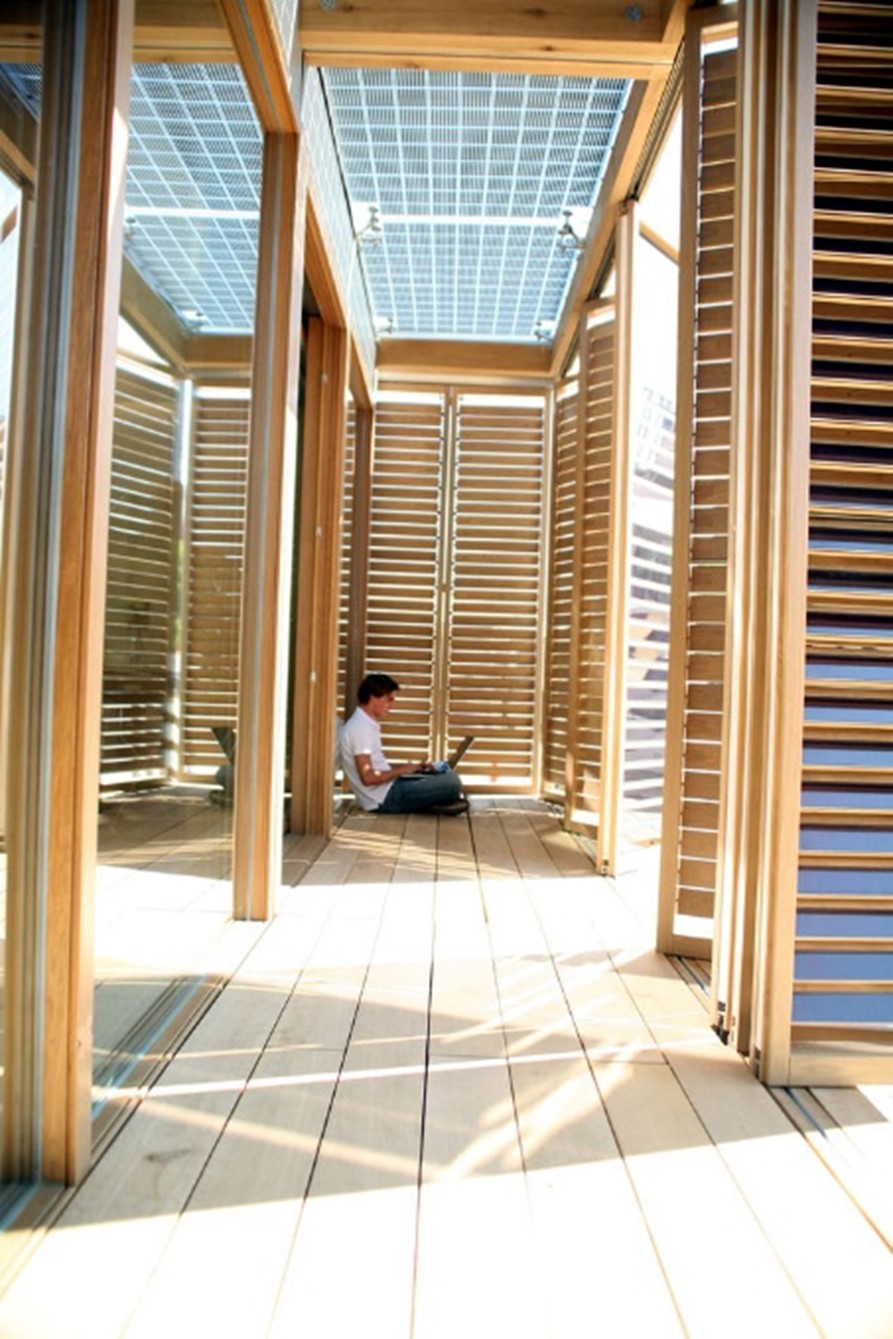
These folding louvered porch doors provide effective shade from low-angle east and west sunlight and can open for views; the photovoltaic panels overhead allow in filtered natural light
Image
![[bundle] design studio built this attached home in the marine climate in Bellingham, WA, and certified it to DOE Zero Energy Ready Home specifications in 2021.](https://basc.pnnl.gov/sites/default/files/images/2021-Bundle-Flc-1-Aerial-Front-Elevation-Roof.jpg)
[bundle] design studio built this attached home in the marine climate in Bellingham, WA, and certified it to DOE Zero Energy Ready Home specifications in 2021.
Image
![[bundle] Design Studio built this custom for buyer home in the marine climate in Bellingham, WA, and certified it to DOE Zero Energy Ready Home specifications in 2021.](https://basc.pnnl.gov/sites/default/files/images/2021-Bundle-Mid-1-Front-Elevation-Yard.jpg)
[bundle] Design Studio built this custom for buyer home in the marine climate in Bellingham, WA, and certified it to DOE Zero Energy Ready Home specifications in 2021.
Image
![[bundle] design studio built this custom spec home in the marine climate in Bellingham, WA, and certified it to Zero Energy Ready Home in 2016.](https://basc.pnnl.gov/sites/default/files/images/2016_Bundle_Birch-1-Front.jpg)
[bundle] design studio built this custom spec home in the marine climate in Bellingham, WA, and certified it to Zero Energy Ready Home in 2016.
Image
Image
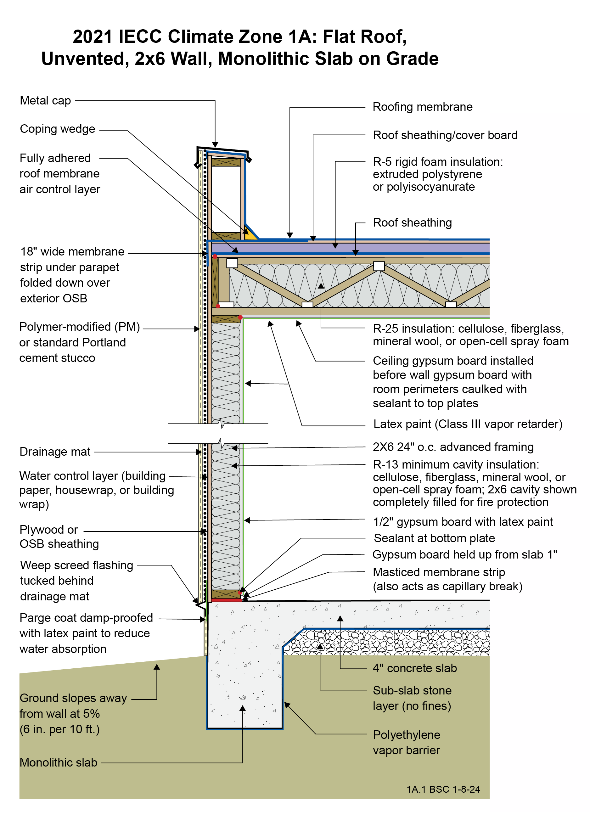
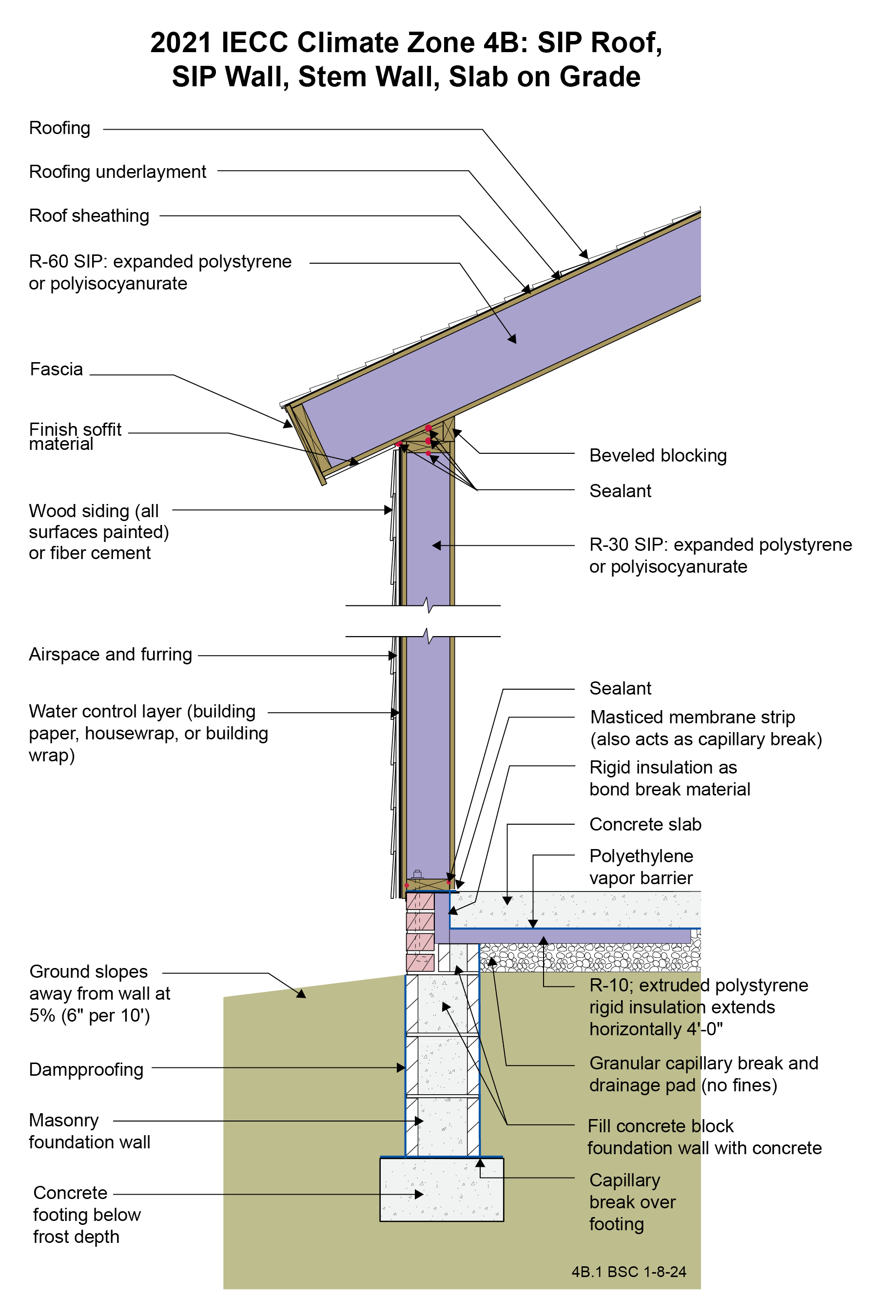
2021 IECC Climate Zone 1A: Flat Roof, Unvented, 2x6 Wall, Monolithic Slab on Grade
Image
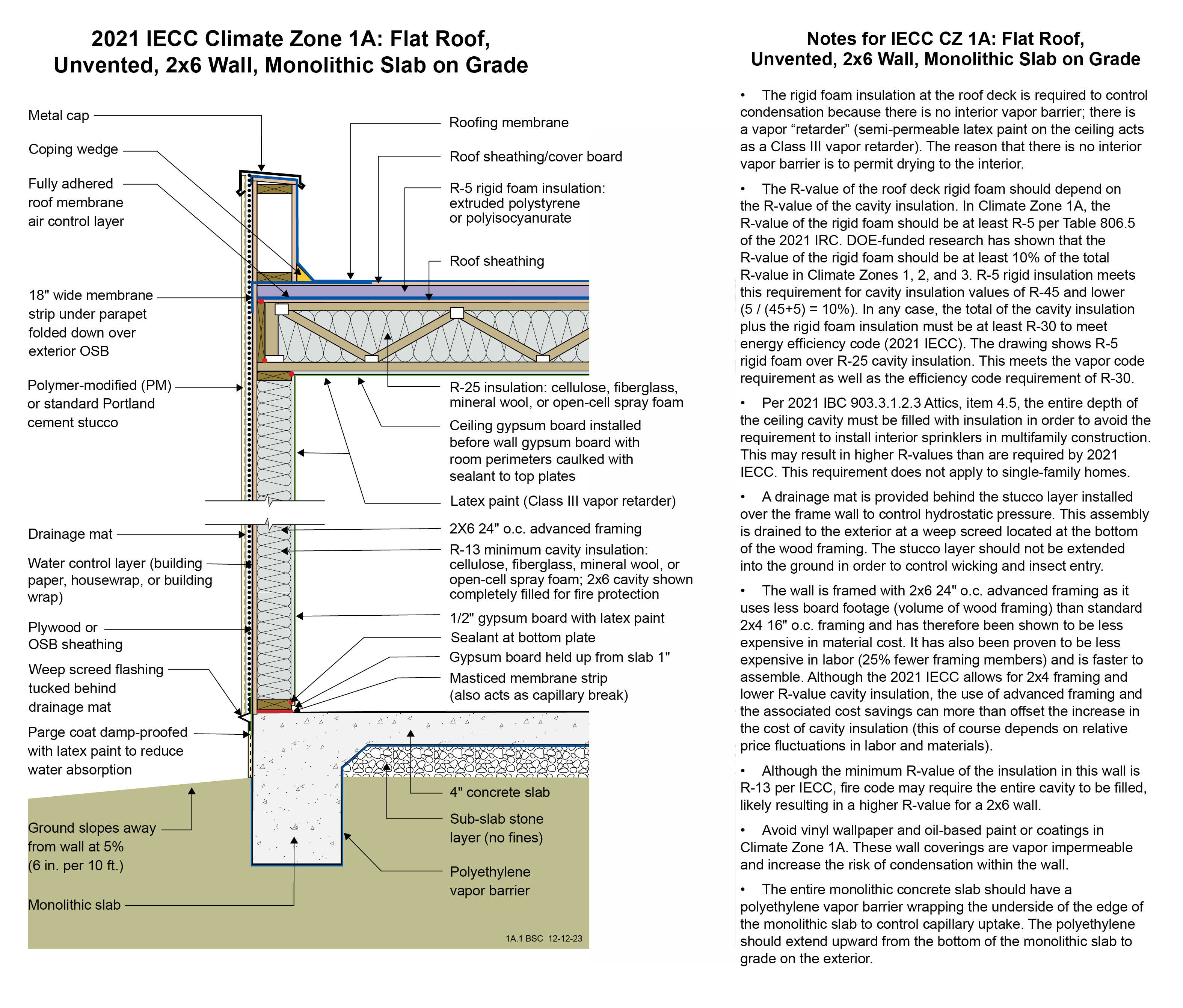
2021 IECC Climate Zone 1A: Flat Roof, Unvented, 2x6 Wall, Monolithic Slab on Grade (with notes)
Image
Image
Image
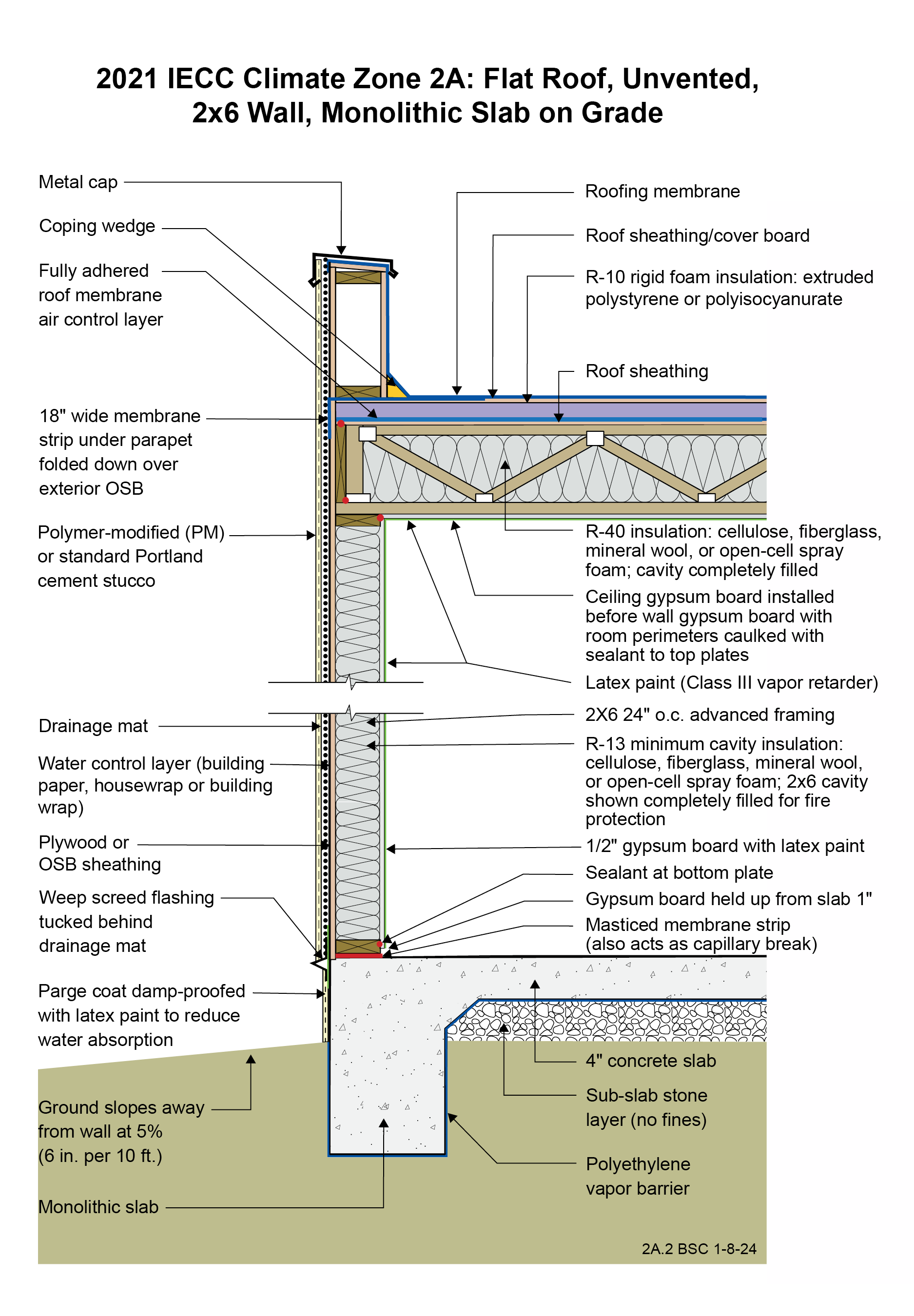
2021 IECC Climate Zone 2A: Flat Roof, Unvented, 2x6 Wall, Monolithic Slab on Grade
Image
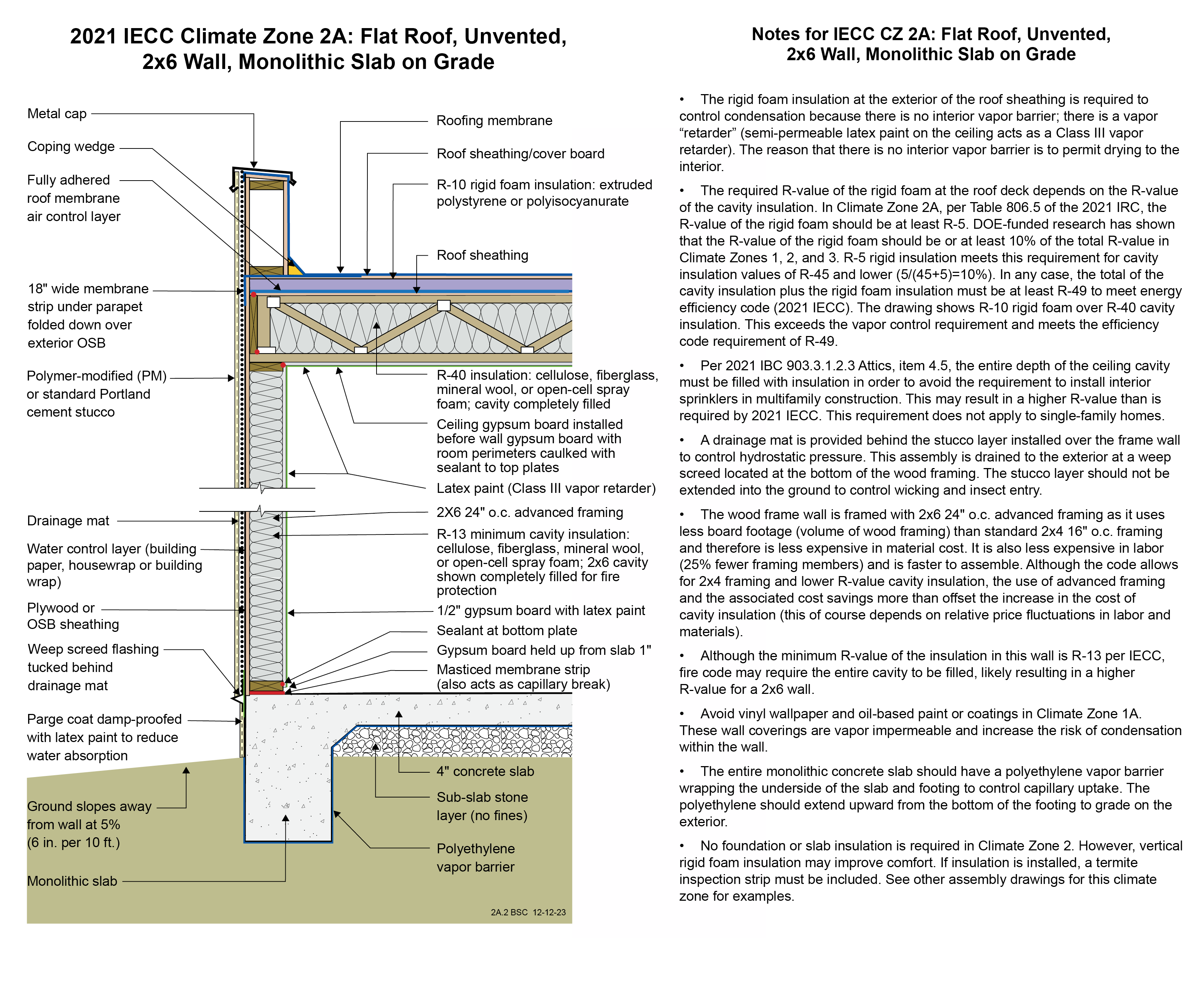
2021 IECC Climate Zone 2A: Flat Roof, Unvented, 2x6 Wall, Monolithic Slab on Grade (with notes)
Image
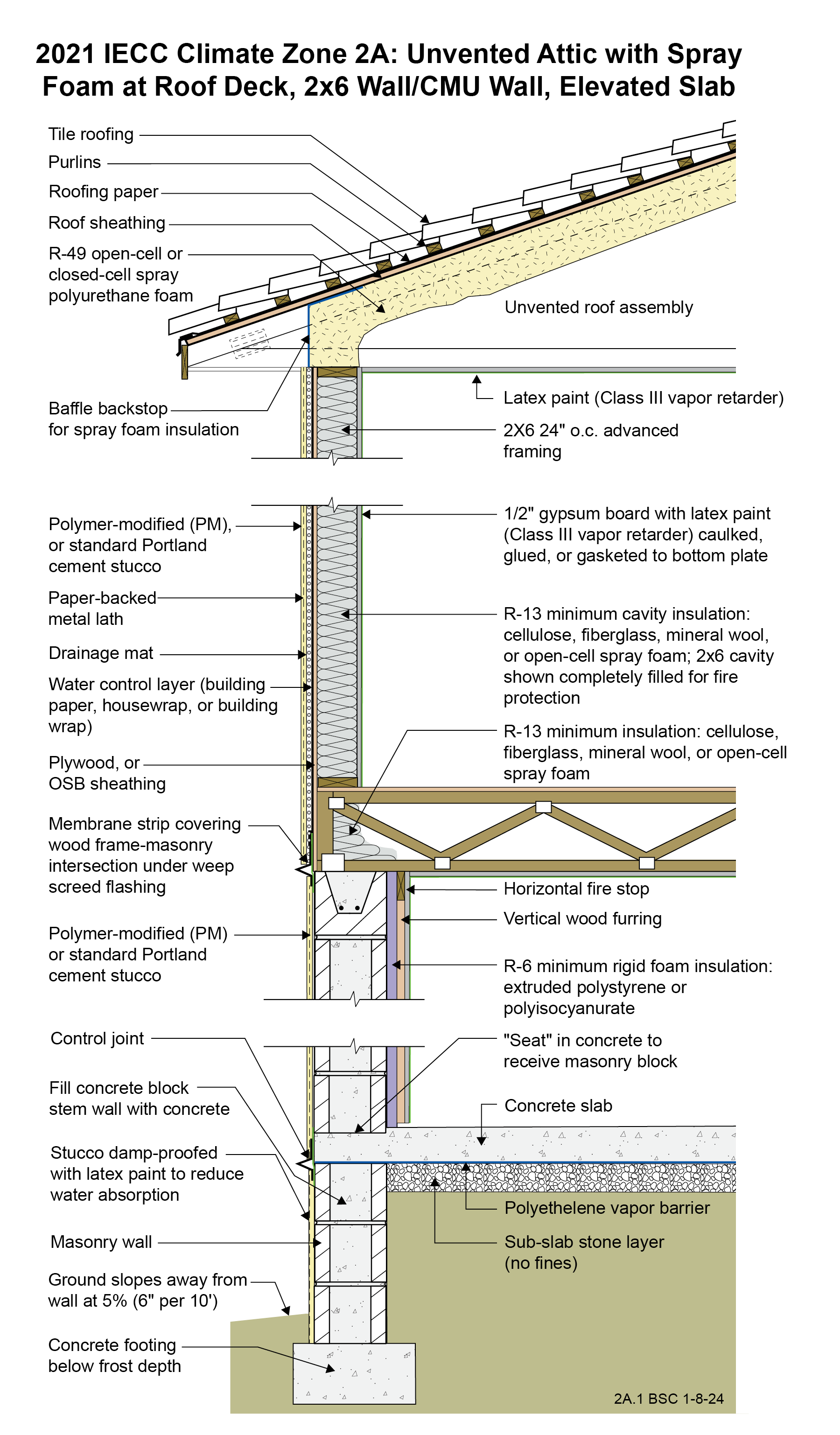
2021 IECC Climate Zone 2A: Unvented Attic with Spray Foam at Roof Deck, 2x6 Wall-CMU Wall, Elevated Slab
Image
Image
Image
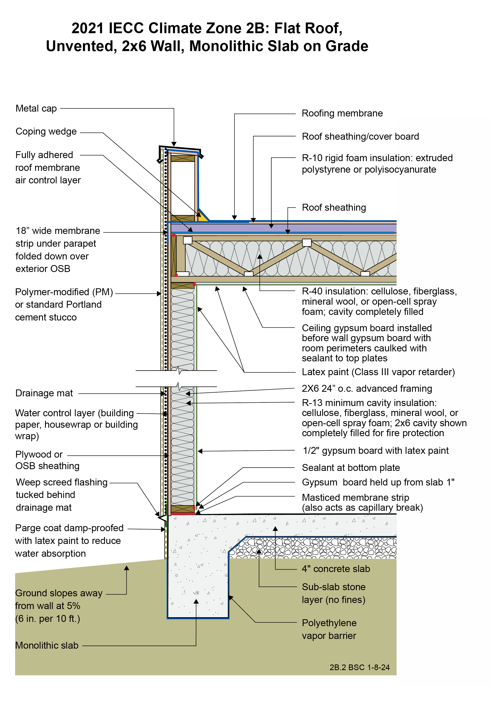
2021 IECC Climate Zone 2B: Flat Roof, Unvented, 2x6 Wall, Monolithic Slab on Grade
Image
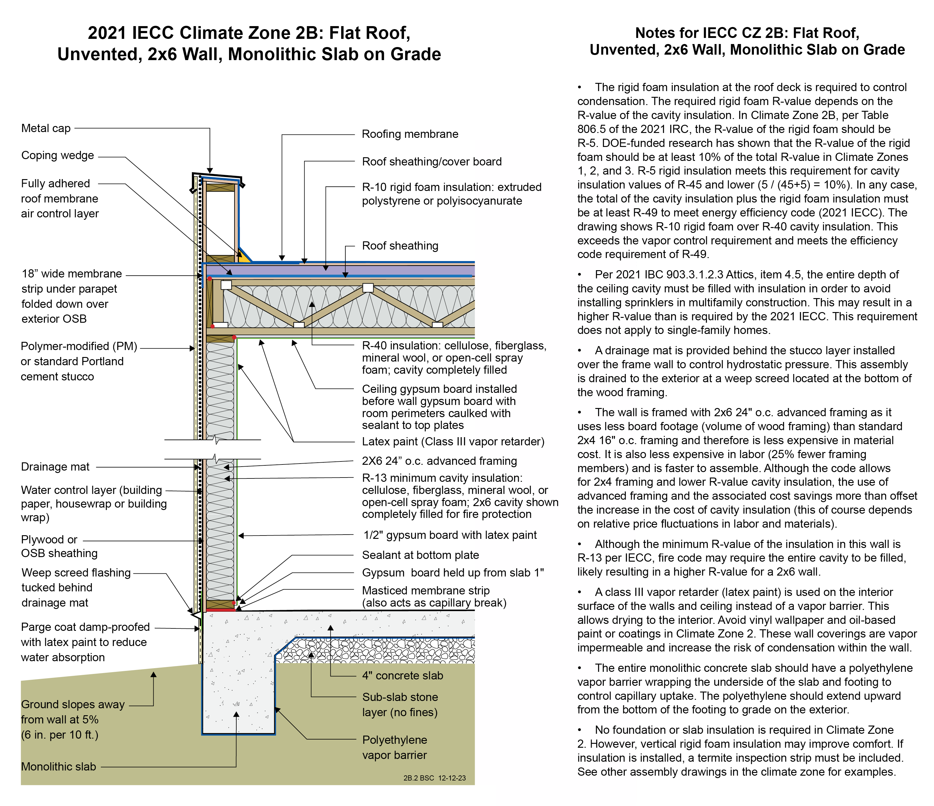
2021 IECC Climate Zone 2B: Flat Roof, Unvented, 2x6 Wall, Monolithic Slab on Grade (with notes)
Image
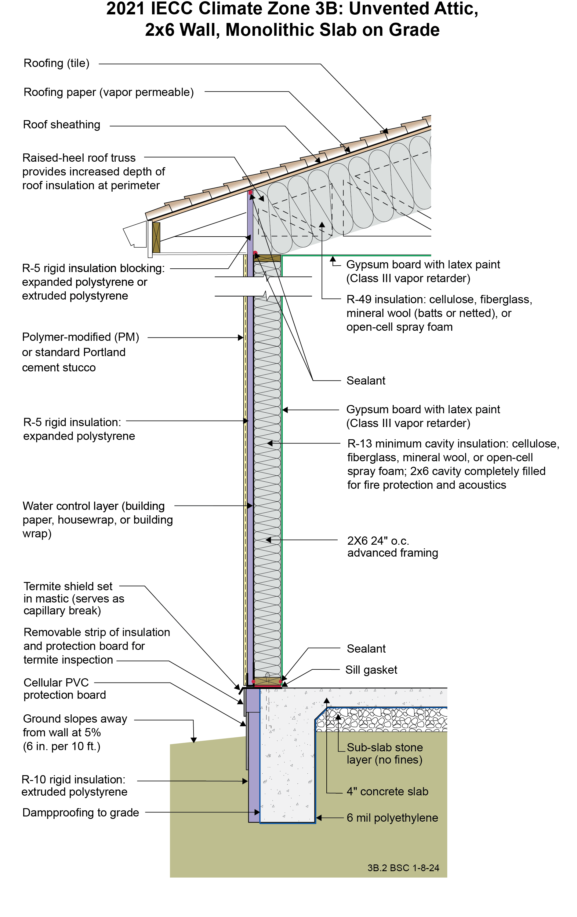
Image
Image
Image
Image
Image
Image
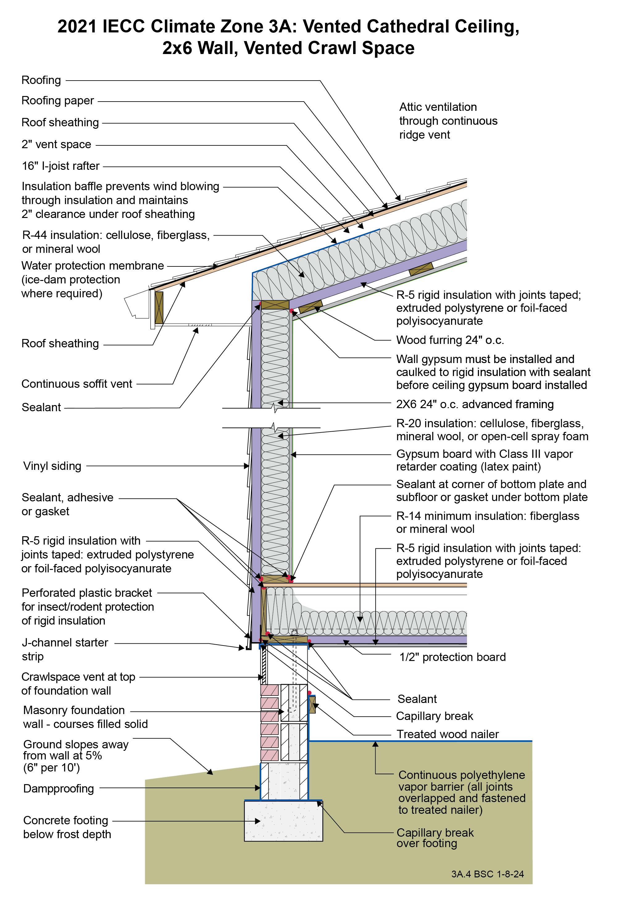
2021 IECC Climate Zone 3A: Vented Cathedral Ceiling, 2x6 Wall, Vented Crawl Space
Image

2021 IECC Climate Zone 3A: Vented Cathedral Ceiling, 2x6 Wall, Vented Crawl Space (with notes)
Image
Image
Image
Image
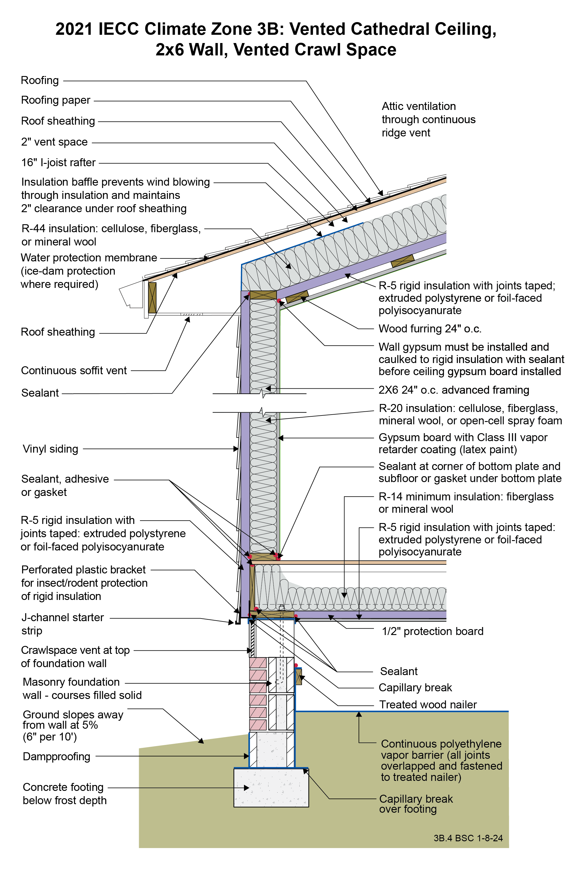
2021 IECC Climate Zone 3B: Vented Cathedral Ceiling, 2x6 Wall, Vented Crawl Space
Image

Image
Image
Image
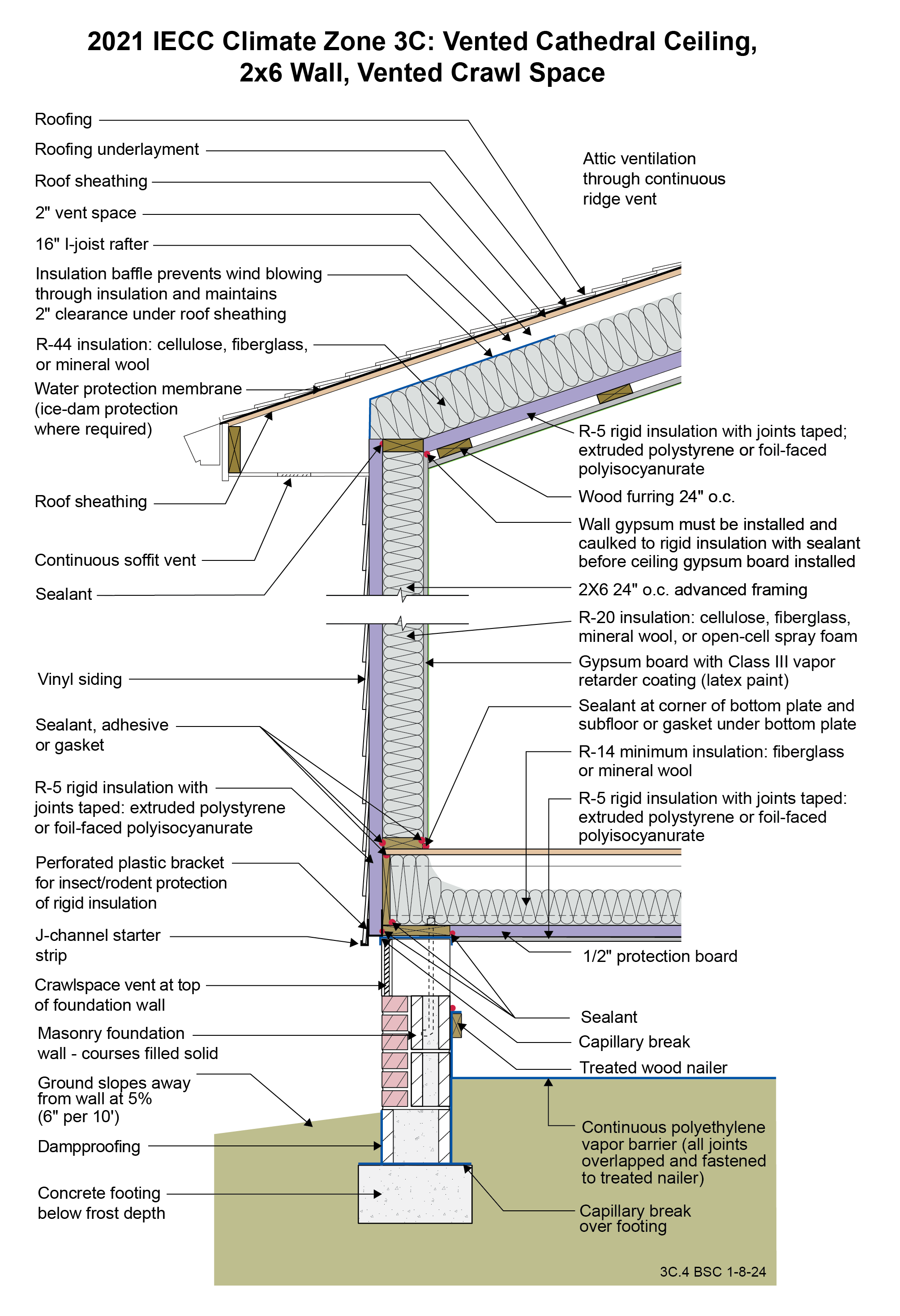
2021 IECC Climate Zone 3C: Vented Cathedral Ceiling, 2x6 Wall, Vented Crawl Space
Image

Image
Image
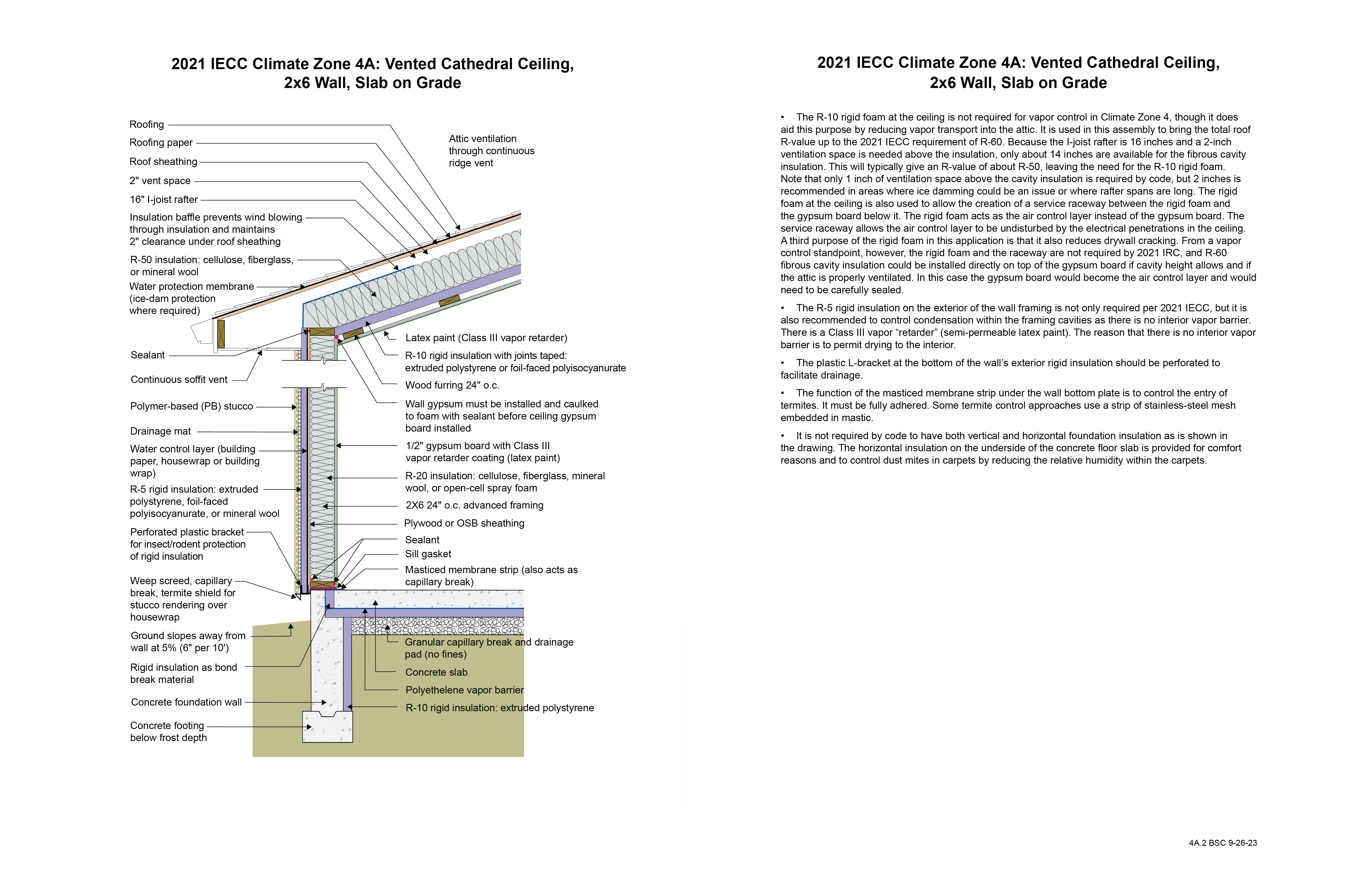
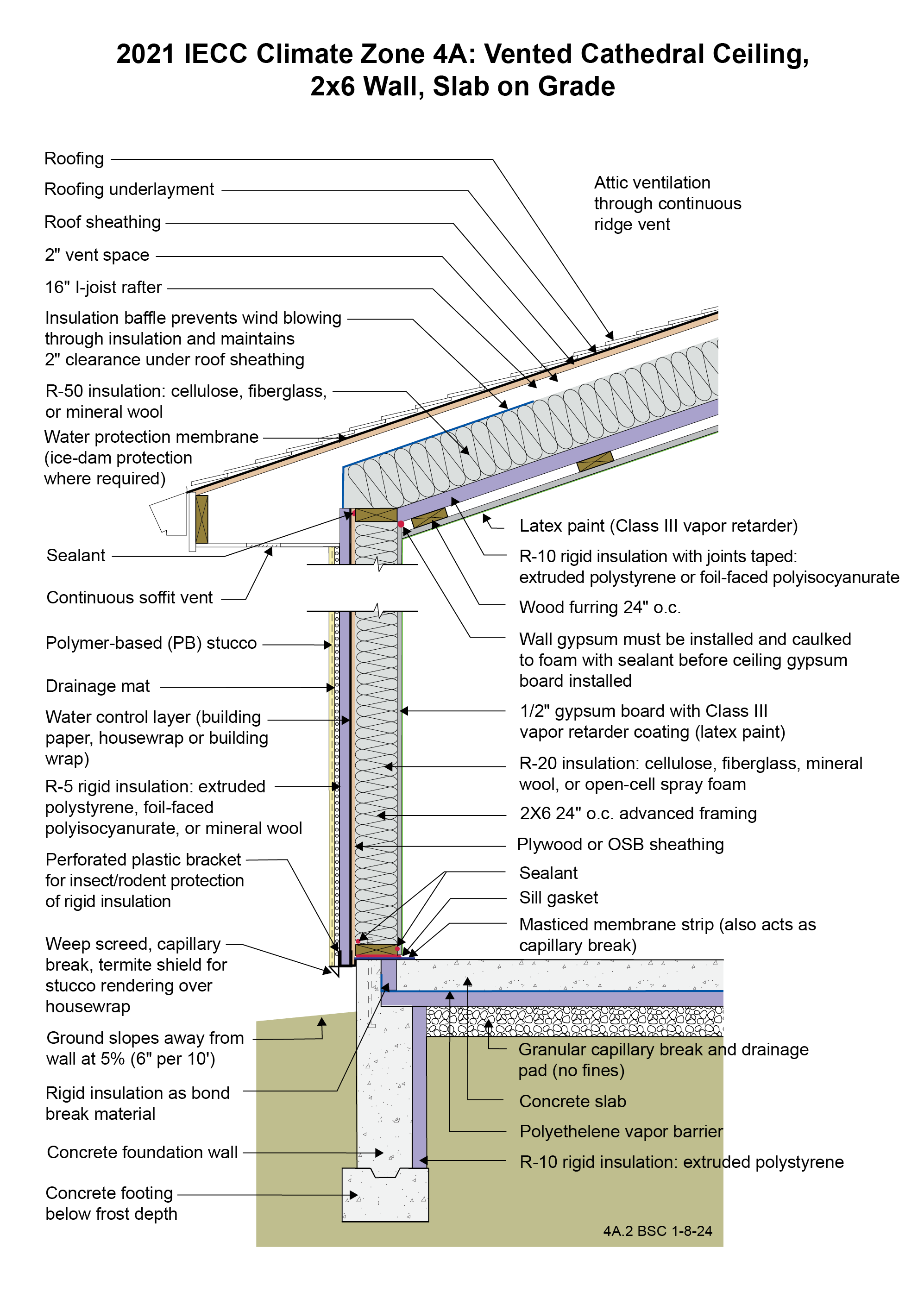
2021 IECC Climate Zone 4A: Vented Cathedral Ceiling, 2x6 Wall, Slab on Grade (with notes)
Image
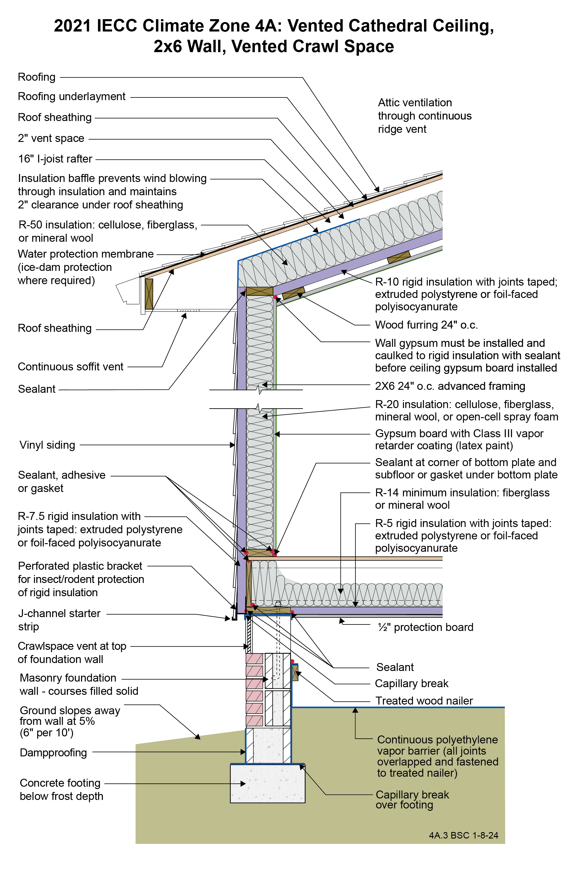
2021 IECC Climate Zone 4A: Vented Cathedral Ceiling, 2x6 Wall, Vented Crawl Space
Image